MICROSTRUCTURING OF MULTIPHASE FOOD SYSTEMS IN SHEAR AND ELONGATIONAL PROCESS FLOWS Prof. Dr. Erich J. Windhab, Dr. Peter Fischer, Dr. Michael Stranzinger, Stefan Kaufmann Swiss Federal Institute of Technology Zürich (ETH), Institute of Food Science; Laboratory of Food Process Engineering; CH-8092 Zürich, Switzerland ABSTRACT A large variety of food systems is treated in dispersing operations in order to generate a homogeneous disperse microstructure which allows to adjust structure- related quality characteristics of the final products. For fine dispersing of disperse structures like solid particles/biological cells, emulsion drops, gas cells and aggregates thereof, the volumetric power and energy inputs are the crucial integral processing parameters but are not sufficient in order to optimize the dispersing efficiency. The flow field characteristics are of additional importance. For most concentrated food systems containing a disperse phase, the dispersing flow field in any apparatus is laminar. However the ratio of shear and elongational laminar flow contributions influences the dispersing efficiency strongly. Beside disperse components most multiphase food systems contain also macromolecular stabilizing components in the continuous phase as well as surfactants at the interfaces. The various disperse and macromolecular components have in general different sensitivity to mechanical stresses acting in dispersing flows. Consequently, there is a need to optimize dispersing flow apparatus and adapt the stresses acting during processing in order to adjust the resulting microstructure. The most important structural characteristics for the disperse phase(s) are size, size distribution and shape which have a strong impact on the rheology of the fluid system and which are preferably focussed within the work reported here. It is shown that in well defined shear and/or elongational dispersing flow fields the disperse particle size distribution and shape can be adjusted in order to generate specific rheological and quality properties of related food systems. It is also demonstrated how the synergistic application of dispersing flow experiments and Computational Fluid Dynamics (CFD) allow to optimize dispersing flow processes and related product properties. INTRODUCTION Micro-structuring in shear- and elongational dispersing flow fields links the areas of process engineering and material engineering. The latter includes the structure- rheology relationships. Rheologically the viscous behaviour of

Welcome message from author
This document is posted to help you gain knowledge. Please leave a comment to let me know what you think about it! Share it to your friends and learn new things together.
Transcript
MICROSTRUCTURING OF MULTIPHASE FOOD SYSTEMS IN SHEARAND ELONGATIONAL PROCESS FLOWS
Prof. Dr. Erich J. Windhab,Dr. Peter Fischer, Dr. Michael Stranzinger, Stefan Kaufmann
Swiss Federal Institute of Technology Zürich (ETH), Institute of Food Science;
Laboratory of Food Process Engineering; CH-8092 Zürich, Switzerland
ABSTRACT
A large variety of food systems is treated in dispersing operations in order to
generate a homogeneous disperse microstructure which allows to adjust structure-
related quality characteristics of the final products. For fine dispersing of disperse
structures like solid particles/biological cells, emulsion drops, gas cells and
aggregates thereof, the volumetric power and energy inputs are the crucial integral
processing parameters but are not sufficient in order to optimize the dispersing
efficiency. The flow field characteristics are of additional importance. For most
concentrated food systems containing a disperse phase, the dispersing flow field in
any apparatus is laminar. However the ratio of shear and elongational laminar flow
contributions influences the dispersing efficiency strongly. Beside disperse
components most multiphase food systems contain also macromolecular stabilizing
components in the continuous phase as well as surfactants at the interfaces. The
various disperse and macromolecular components have in general different
sensitivity to mechanical stresses acting in dispersing flows.
Consequently, there is a need to optimize dispersing flow apparatus and adapt
the stresses acting during processing in order to adjust the resulting microstructure.
The most important structural characteristics for the disperse phase(s) are size, size
distribution and shape which have a strong impact on the rheology of the fluid
system and which are preferably focussed within the work reported here.
It is shown that in well defined shear and/or elongational dispersing flow fields
the disperse particle size distribution and shape can be adjusted in order to generate
specific rheological and quality properties of related food systems. It is also
demonstrated how the synergistic application of dispersing flow experiments and
Computational Fluid Dynamics (CFD) allow to optimize dispersing flow processes
and related product properties.
INTRODUCTION
Micro-structuring in shear- and elongational dispersing flow fields links the
areas of process engineering and material engineering. The latter includes the
structure- rheology relationships. Rheologically the viscous behaviour of
multiphase food systems is in general non-Newtonian, mostly shear-thinning and
time-dependent. In many cases elastic properties are also not negligible. Dispersing
as a flow structuring unit operation regarded here, generates the product
microstructure due to shear- and normal stresses which act in the dispersing flow
velocity field. A detailed description of the velocity field can be received from flow
visualization experiments and from Computational Fluid Dynamics (CFD). The
coupling of local velocity field information and rheological material functions
which are received from rheometric shear and elongation experiments, allow for
determining the related local shear and normal stress distributions. Micro-
structuring is triggered by the stresses acting locally in the flow field and occurs in
general if critical stresses of the “structuring units” like networks, droplets, particle
aggregates are exceeded. In order to generate a flow-induced structure the
structuring units have to experience along their flow tracks a certain total
deformation which requires a sufficient shear-/elongational rates and residence
times.
STRUCTURE RHEOLOGY RELATIONSHIPS
Laminar flow fields are of uni- or multiaxial shear or elongational nature or a
mixture of both. Within such flows, the rheological behaviour mirrors the dynamic
behaviour of structural units which can change by orientation, deformation and
aggregation or de-aggregation (= structuring mechanisms). The latter is
synonymous to dispersing.
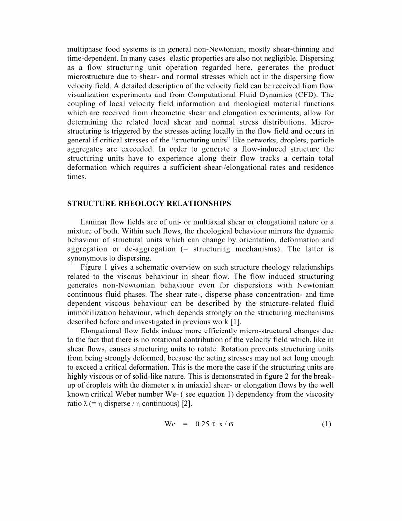
Figure 1 gives a schematic overview on such structure rheology relationships
related to the viscous behaviour in shear flow. The flow induced structuring
generates non-Newtonian behaviour even for dispersions with Newtonian
continuous fluid phases. The shear rate-, disperse phase concentration- and time
dependent viscous behaviour can be described by the structure-related fluid
immobilization behaviour, which depends strongly on the structuring mechanisms
described before and investigated in previous work [1].
Elongational flow fields induce more efficiently micro-structural changes due
to the fact that there is no rotational contribution of the velocity field which, like in
shear flows, causes structuring units to rotate. Rotation prevents structuring units
from being strongly deformed, because the acting stresses may not act long enough
to exceed a critical deformation. This is the more the case if the structuring units are
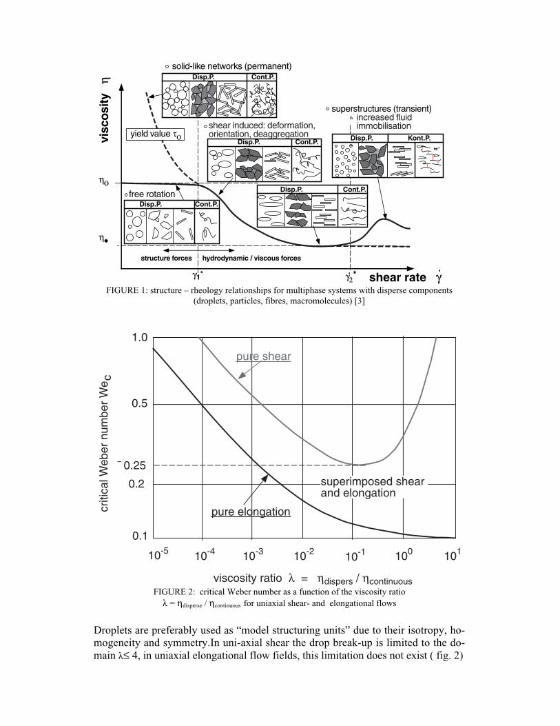
highly viscous or of solid-like nature. This is demonstrated in figure 2 for the break-
up of droplets with the diameter x in uniaxial shear- or elongation flows by the well
known critical Weber number We- ( see equation 1) dependency from the viscosity
ratio λ (= η disperse / η continuous) [2].
We = 0.25 τ x / σ (1)
Disp.P. Cont.P.
Disp.P. Cont.P.
Disp.P. Cont.P.
Disp.P. Cont.P.
visc
osi
ty
η
γ1*
ηο
η••
yield value το
structure forces hydrodynamic / viscous forces
γ2*
increased fluidimmobilisation
solid-like networks (permanent)
shear induced: deformation,orientation, deaggregation
free rotation
shear rate γ
superstructures (transient)
Disp.P. Kont.P.
FIGURE 1: structure – rheology relationships for multiphase systems with disperse components
(droplets, particles, fibres, macromolecules) [3]
10-5 10010-110-210-310-4 101
1.0
0.1
0.2
0.5
¯ 0.25
pure shear
pure elongationcriti
cal W
eber
num
ber
We
c
viscosity ratio λ = ηdispers / ηcontinuous
superimposed shear and elongation
FIGURE 2: critical Weber number as a function of the viscosity ratio
λ = ηdisperse / ηcontinuous for uniaxial shear- and elongational flows
Droplets are preferably used as “model structuring units” due to their isotropy, ho-
mogeneity and symmetry.In uni-axial shear the drop break-up is limited to the do-
main λ≤ 4, in uniaxial elongational flow fields, this limitation does not exist ( fig. 2)
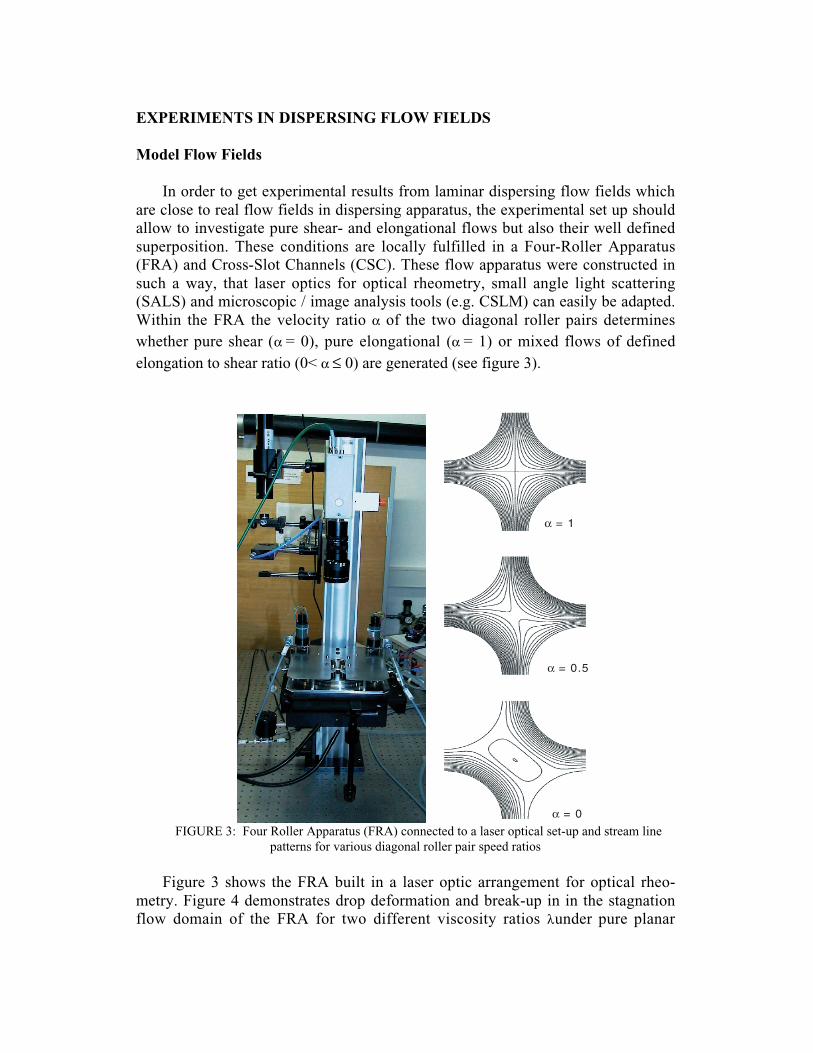
EXPERIMENTS IN DISPERSING FLOW FIELDS
Model Flow Fields
In order to get experimental results from laminar dispersing flow fields which
are close to real flow fields in dispersing apparatus, the experimental set up should
allow to investigate pure shear- and elongational flows but also their well defined
superposition. These conditions are locally fulfilled in a Four-Roller Apparatus
(FRA) and Cross-Slot Channels (CSC). These flow apparatus were constructed in
such a way, that laser optics for optical rheometry, small angle light scattering
(SALS) and microscopic / image analysis tools (e.g. CSLM) can easily be adapted.
Within the FRA the velocity ratio α of the two diagonal roller pairs determines
whether pure shear (α = 0), pure elongational (α = 1) or mixed flows of defined
elongation to shear ratio (0< α ≤ 0) are generated (see figure 3).
α = 1
α = 0.5
α = 0
FIGURE 3: Four Roller Apparatus (FRA) connected to a laser optical set-up and stream line
patterns for various diagonal roller pair speed ratios
Figure 3 shows the FRA built in a laser optic arrangement for optical rheo-
metry. Figure 4 demonstrates drop deformation and break-up in in the stagnation
flow domain of the FRA for two different viscosity ratios λ under pure planar
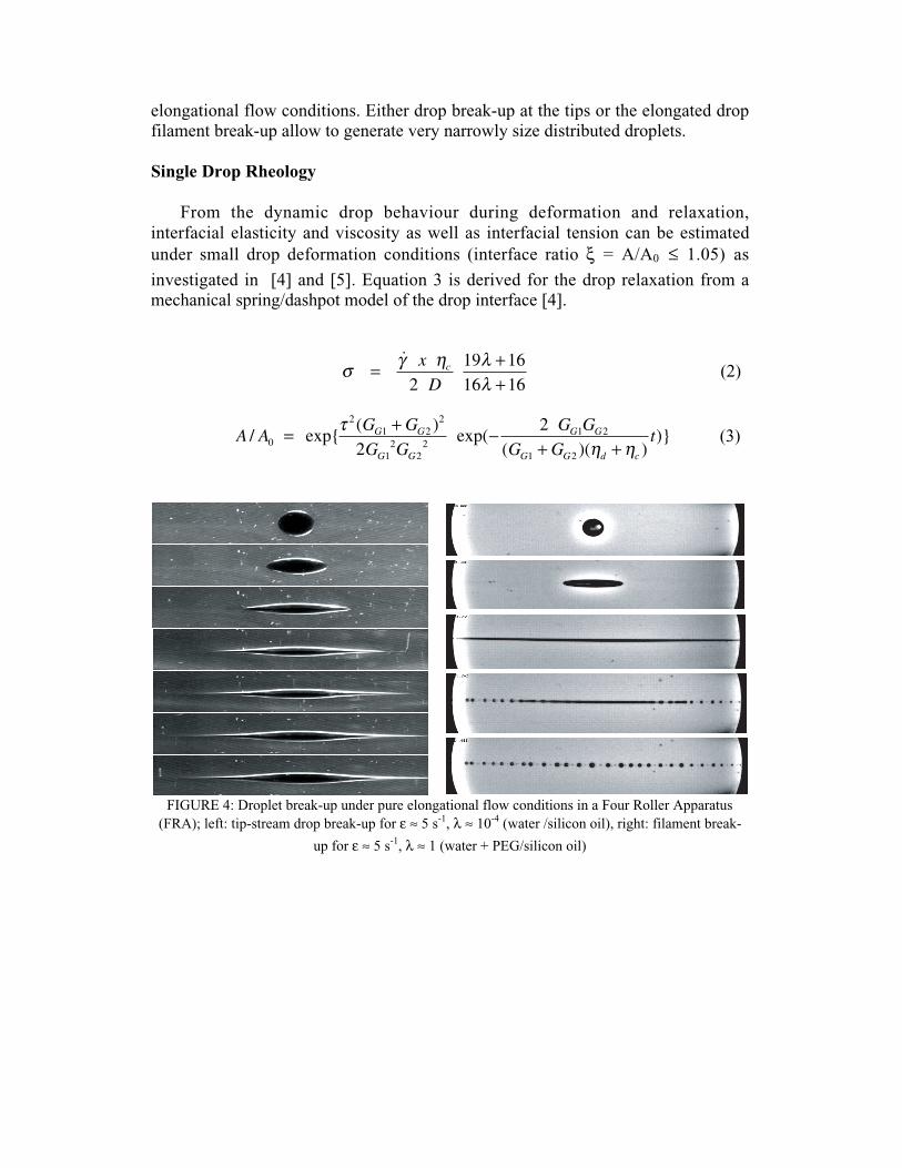
elongational flow conditions. Either drop break-up at the tips or the elongated drop
filament break-up allow to generate very narrowly size distributed droplets.
Single Drop Rheology
From the dynamic drop behaviour during deformation and relaxation,
interfacial elasticity and viscosity as well as interfacial tension can be estimated
under small drop deformation conditions (interface ratio ξ = A/A0 ≤ 1.05) as
investigated in [4] and [5]. Equation 3 is derived for the drop relaxation from a
mechanical spring/dashpot model of the drop interface [4].
σ γ η λλ
˙
= +
+x
Dc
219 1616 16
(2)
A AG G
G G
G G
G GtG G
G G
G G
G G d c
/ exp{( )
exp(
( )( ))}0
21 2
2
12
22
1 2
1 222= + −+ +
τη η
(3)
FIGURE 4: Droplet break-up under pure elongational flow conditions in a Four Roller Apparatus
(FRA); left: tip-stream drop break-up for ε ≈ 5 s-1
, λ ≈ 10-4
(water /silicon oil), right: filament break-
up for ε ≈ 5 s-1
, λ ≈ 1 (water + PEG/silicon oil)
droplet size x / µm
0
0.05
0.1
0.15
0.2
0.25
0.3
1 10 100 1000
50 1/s
300 1/s
500 1/s
800 1/s
num
ber
vol.
dist
ribut
ion
q3(
x)
dispersing
coalescencePv
hc
FIGURE 5: equilibrium drop size distributions after shear at various constant shear rates (pure
uniaxial shear in concentric cylinder gap) [6]
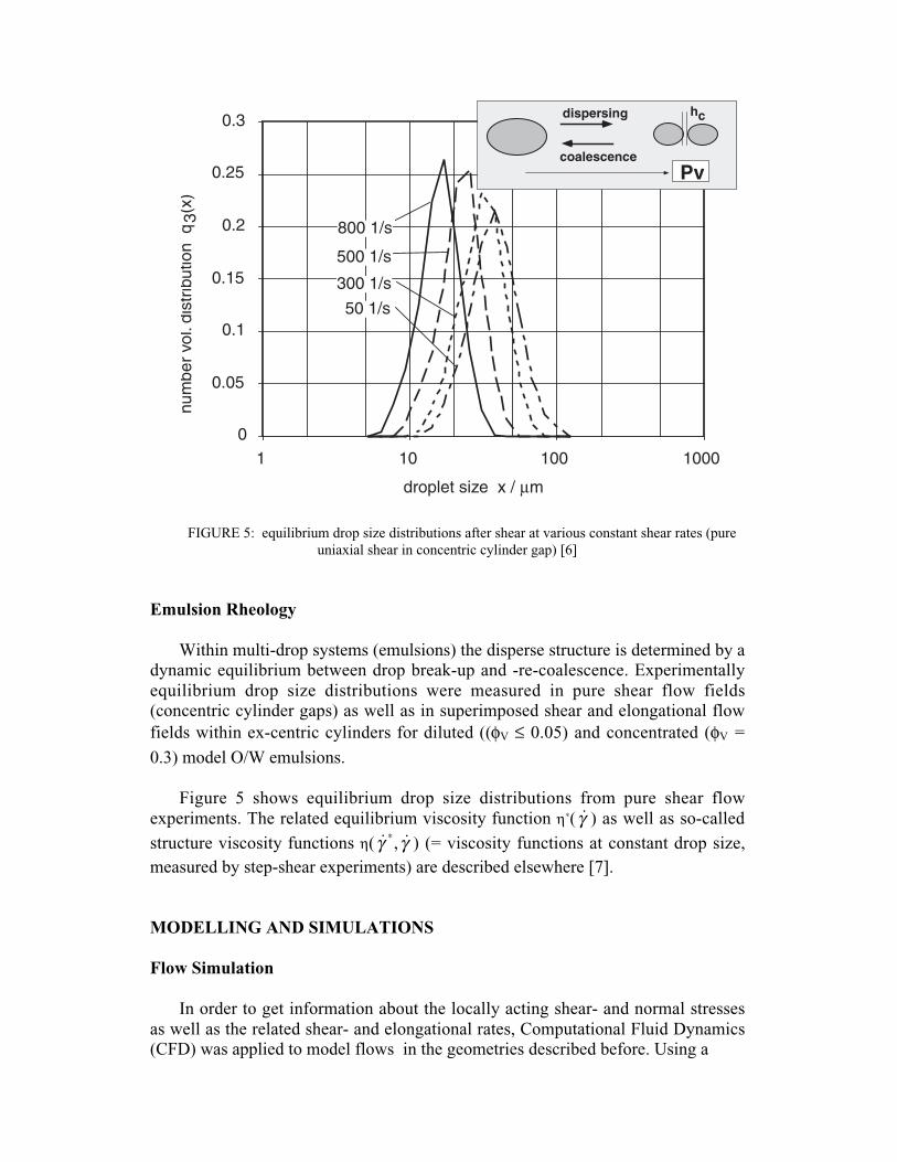
Emulsion Rheology
Within multi-drop systems (emulsions) the disperse structure is determined by a
dynamic equilibrium between drop break-up and -re-coalescence. Experimentally
equilibrium drop size distributions were measured in pure shear flow fields
(concentric cylinder gaps) as well as in superimposed shear and elongational flow
fields within ex-centric cylinders for diluted ((φV ≤ 0.05) and concentrated (φV =
0.3) model O/W emulsions.
Figure 5 shows equilibrium drop size distributions from pure shear flow
experiments. The related equilibrium viscosity function η∗( γ̇ ) as well as so-called
structure viscosity functions η( ˙*γ , γ̇ ) (= viscosity functions at constant drop size,
measured by step-shear experiments) are described elsewhere [7].
MODELLING AND SIMULATIONS
Flow Simulation
In order to get information about the locally acting shear- and normal stresses
as well as the related shear- and elongational rates, Computational Fluid Dynamics
(CFD) was applied to model flows in the geometries described before. Using a
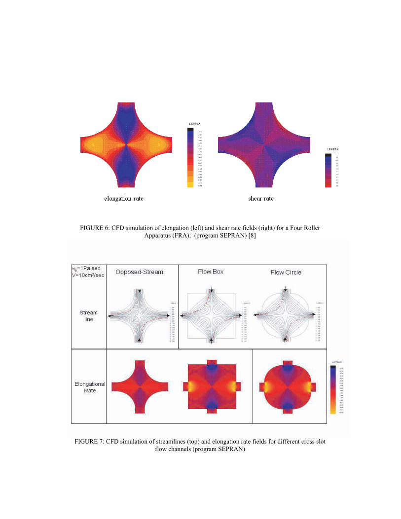
FIGURE 6: CFD simulation of elongation (left) and shear rate fields (right) for a Four Roller
Apparatus (FRA); (program SEPRAN) [8]
FIGURE 7: CFD simulation of streamlines (top) and elongation rate fields for different cross slot
flow channels (program SEPRAN)
partly modified finite element code (SEPRAN), the shear- and elongation rate fields
were calculated by solving the typical equations for mass-, energy- and momentum
conservation. Results are shown exemplary for the FRA in figure 6. Figure 7
demonstrates additionally elongation rate fields in three different experimentally
investigated cross-slot flow channels. From such calculations the stress/strain -
history (SSH) of droplets or other structuring elements respectively along flow
tracks (particle tracks) within the apparatus flow, can be derived. The application of
such a particle tracking calculation is demonstrated in the chapter where real
rotor/stator-dispersing flow geometries are described.
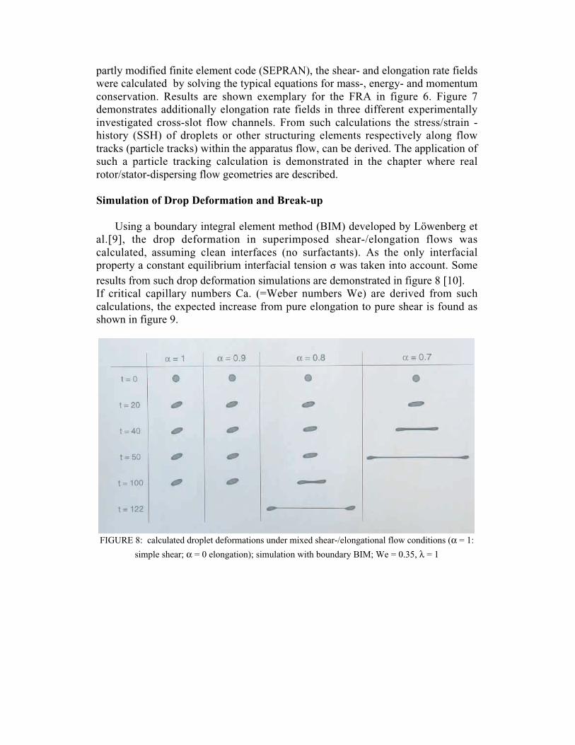
Simulation of Drop Deformation and Break-up
Using a boundary integral element method (BIM) developed by Löwenberg et
al.[9], the drop deformation in superimposed shear-/elongation flows was
calculated, assuming clean interfaces (no surfactants). As the only interfacial
property a constant equilibrium interfacial tension σ was taken into account. Some
results from such drop deformation simulations are demonstrated in figure 8 [10].
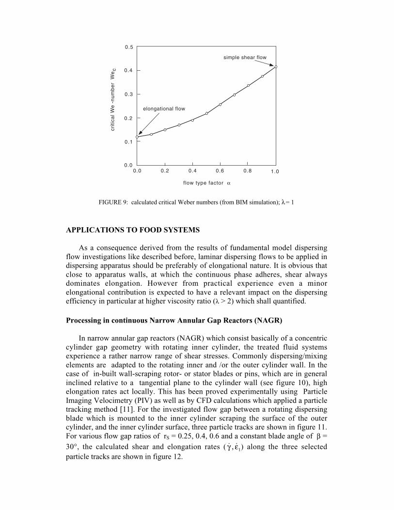
If critical capillary numbers Ca. (=Weber numbers We) are derived from such
calculations, the expected increase from pure elongation to pure shear is found as
shown in figure 9.
FIGURE 8: calculated droplet deformations under mixed shear-/elongational flow conditions (α = 1:
simple shear; α = 0 elongation); simulation with boundary BIM; We = 0.35, λ = 1
elongational flow
simple shear flow
0.5
0.1
0.2
0.3
0.4
0.00.40.20.0 0.80.6 1.0
crit
ica
l W
e -
nu
mb
er
We
c
f low type factor α
FIGURE 9: calculated critical Weber numbers (from BIM simulation); λ = 1
APPLICATIONS TO FOOD SYSTEMS
As a consequence derived from the results of fundamental model dispersing
flow investigations like described before, laminar dispersing flows to be applied in
dispersing apparatus should be preferably of elongational nature. It is obvious that
close to apparatus walls, at which the continuous phase adheres, shear always
dominates elongation. However from practical experience even a minor
elongational contribution is expected to have a relevant impact on the dispersing
efficiency in particular at higher viscosity ratio (λ > 2) which shall quantified.
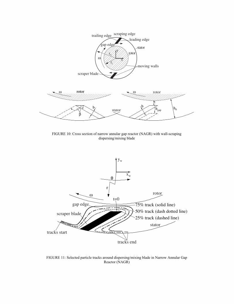
Processing in continuous Narrow Annular Gap Reactors (NAGR)
In narrow annular gap reactors (NAGR) which consist basically of a concentric
cylinder gap geometry with rotating inner cylinder, the treated fluid systems
experience a rather narrow range of shear stresses. Commonly dispersing/mixing
elements are adapted to the rotating inner and /or the outer cylinder wall. In the
case of in-built wall-scraping rotor- or stator blades or pins, which are in general
inclined relative to a tangential plane to the cylinder wall (see figure 10), high
elongation rates act locally. This has been proved experimentally using Particle
Imaging Velocimetry (PIV) as well as by CFD calculations which applied a particle
tracking method [11]. For the investigated flow gap between a rotating dispersing
blade which is mounted to the inner cylinder scraping the surface of the outer
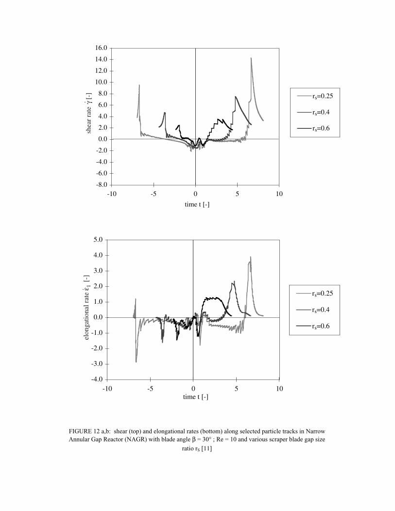
cylinder, and the inner cylinder surface, three particle tracks are shown in figure 11.
For various flow gap ratios of rS = 0.25, 0.4, 0.6 and a constant blade angle of β =
30°, the calculated shear and elongation rates ( γ̇ , ε̇1) along the three selected
particle tracks are shown in figure 12.
x
y
moving walls
trailing edge scraping edge
leading edgegap edge
ωrotor
stator
scraper blade
ro
ri
rotorω rotor
stator
ω rotor
βh0hgap
bb
FIGURE 10: Cross section of narrow annular gap reactor (NAGR) with wall-scraping
dispersing/mixing blade
25% track (dashed line)scraper blade
rotor
stator
50% track (dash dotted line)
75% track (solid line)
ω
gap edget=0
tracks start
tracks end
xw
yw
r
θ
FIGURE 11: Selected particle tracks around dispersing/mixing blade in Narrow Annular Gap
Reactor (NAGR)
shea
r ra
te γ
[-]
⋅
time t [-]
-8.0
-6.0
-4.0
-2.0
0.0
2.0
4.0
6.0
8.0
10.0
12.0
14.0
16.0
-10 -5 0 5 10
rs=0.25
rs=0.4
rs=0.6
-4.0
-3.0
-2.0
-1.0
0.0
1.0
2.0
3.0
4.0
5.0
-10 -5 0 5 10
rs=0.25
rs=0.4
rs=0.6
time t [-]
elon
gatio
nal r
ate
ε 1 [-
]
FIGURE 12 a,b: shear (top) and elongational rates (bottom) along selected particle tracks in Narrow
Annular Gap Reactor (NAGR) with blade angle β = 30° ; Re = 10 and various scraper blade gap size
ratio rS [11]
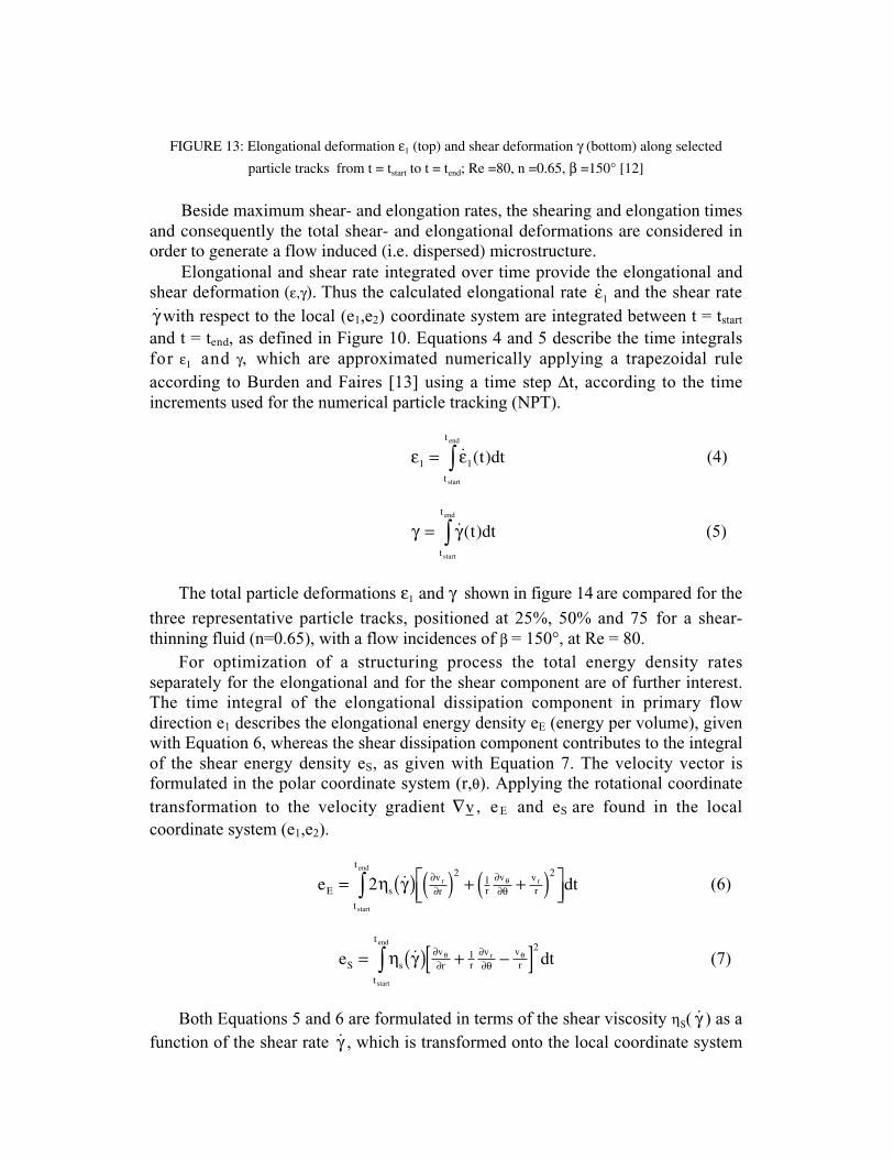
FIGURE 13: Elongational deformation ε1 (top) and shear deformation γ (bottom) along selected
particle tracks from t = tstart to t = tend; Re =80, n =0.65, β =150° [12]
Beside maximum shear- and elongation rates, the shearing and elongation timesand consequently the total shear- and elongational deformations are considered inorder to generate a flow induced (i.e. dispersed) microstructure.
Elongational and shear rate integrated over time provide the elongational and
shear deformation (ε,γ). Thus the calculated elongational rate ε̇1 and the shear rate
γ̇ with respect to the local (e1,e2) coordinate system are integrated between t = tstart
and t = tend, as defined in Figure 10. Equations 4 and 5 describe the time integrals
for ε1 and γ, which are approximated numerically applying a trapezoidal rule
according to Burden and Faires [13] using a time step ∆t, according to the time
increments used for the numerical particle tracking (NPT).
ε ε1 1= ∫ ˙ ( )t dtt
t
start
end
(4)
γ γ= ∫ ˙ ( )t dtt
t
start
end
(5)
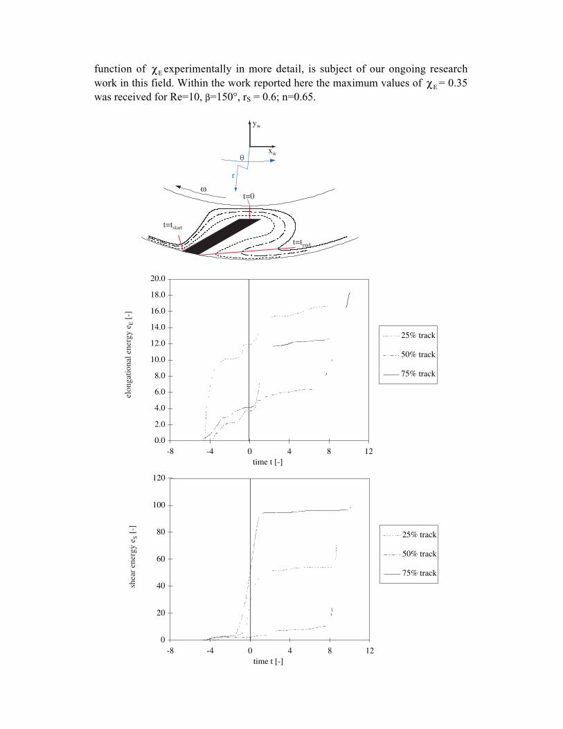
The total particle deformations ε1 and γ shown in figure 14 are compared for the
three representative particle tracks, positioned at 25%, 50% and 75 for a shear-
thinning fluid (n=0.65), with a flow incidences of β = 150°, at Re = 80.
For optimization of a structuring process the total energy density rates
separately for the elongational and for the shear component are of further interest.
The time integral of the elongational dissipation component in primary flow
direction e1 describes the elongational energy density eE (energy per volume), given
with Equation 6, whereas the shear dissipation component contributes to the integral
of the shear energy density eS, as given with Equation 7. The velocity vector is
formulated in the polar coordinate system (r,θ). Applying the rotational coordinate
transformation to the velocity gradient ∇v , e E and eS are found in the local
coordinate system (e1,e2).
e dtE s
t
tvr r
v vr
start
end
r r= ( ) ( ) + +( )
∫ 2
21
2η γ ∂
∂∂∂θ
θ˙ (6)
e dtS s
t
tvr r
v vr
start
end
r= ( ) + −[ ]∫ η γ ∂∂
∂∂θ
θ θ˙ 12
(7)
Both Equations 5 and 6 are formulated in terms of the shear viscosity ηS( γ̇ ) as a
function of the shear rate γ̇ , which is transformed onto the local coordinate system
(e1,e2) ( γ̇ is the magnitude of the rate-of-strain tensor γ̇ , see Equation 3.36). For the
investigated non Newtonian model fluid system with a watery CMC solution as the
continuous fluid phase, ηS( γ̇ ) was described by a Carreau -Yasuda (CY) model
defined by Equation 8.
η ηη η
λ γ−−
= +∞
∞
−
0
11 [ ( ˙) ]* ( ) /a n a (8)
Approximating the time integrals between t = tstart and t = te n d applying a
trapezoidal rule, the expressions eE and eS can be found numerically. The flow
structuring shear- and elongation related volumetric energy inputs according to
Equations 5 and 6 are also compared for the three representative particle tracks,
positioned at 25%, 50% and 75% of the scraper blade gap width hgap. Figure 14
shows the increase of eE and eS as a function of time between t = tstart and t = tend
along the three representative particle tracks for a shear-thinning fluid (n=0.65) with
β = 150° at Re=80. All elongational and shear energies commonly develop in a step
function manner. This behaviour is caused by the pronounced turning sections of
the tracks around the scraper blade.
Summarizing the CFD results it can be stated that the main influence on the
deformation energy depicts the flow incidence, which varies the total average
elongational energy by about 95% between blade angles of β=30° and β=110°. The
maximum change for the total average shear energy at β=90° and β=110° is
calculated as 33%.
Comparing the impact of the rotor velocity with the influence of the flow
incidence, variations of the scraper blade angle cause higher structuring anisotropy
with respect to elongational and shear strain, than increasing the Reynolds number
between 10 and 80. All flow cases show larger total shear energies than total
elongational energies. The minimum difference is found for Re=10, β=30°, n=0.65
with a factor of 3.5
In order to express the flow structuring energy contributions of the two
distinguished flow types (shear, elongation), Equations 9 and 10 define the (local)
flow type contribution factors χE , χS with regard to the investigated scraper blades,
for elongational flow χE and shear flow χS , respectively.
χEE
tot
ee
= (9)
χSS
tot
ee
= (10)
χE ≥ 0.14 which was the lowest contribution factor for the elongational flow
type showed already a qualitative improvement of the dispersing efficiency (i.e.
drop size reduction) at constant energy input, compared to a pure shear flow field
(concentric cylinder gap). To quantify the improvement of dispersing efficiency as a
function of χE experimentally in more detail, is subject of our ongoing research
work in this field. Within the work reported here the maximum values of χE = 0.35
was received for Re=10, β=150°, rS = 0.6; n=0.65.
elon
gati
onal
ene
rgy
e E [
-]
0.0
2.0
4.0
6.0
8.0
10.0
12.0
14.0
16.0
18.0
20.0
-8 -4 0 4 8 12time t [-]
25% track
50% track
75% track
0
20
40
60
80
100
120
-8 -4 0 4 8 12time t [-]
25% track
50% track
75% track
shea
r en
ergy
eS [
-]
t=tend
t=tstart
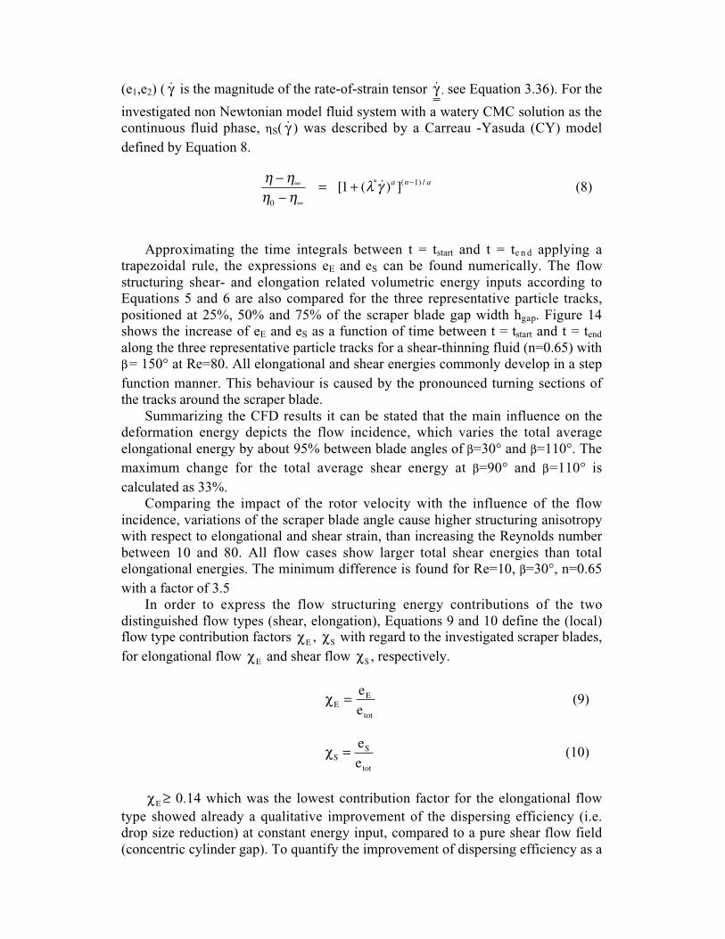
ωt=0
xw
yw
r
θ
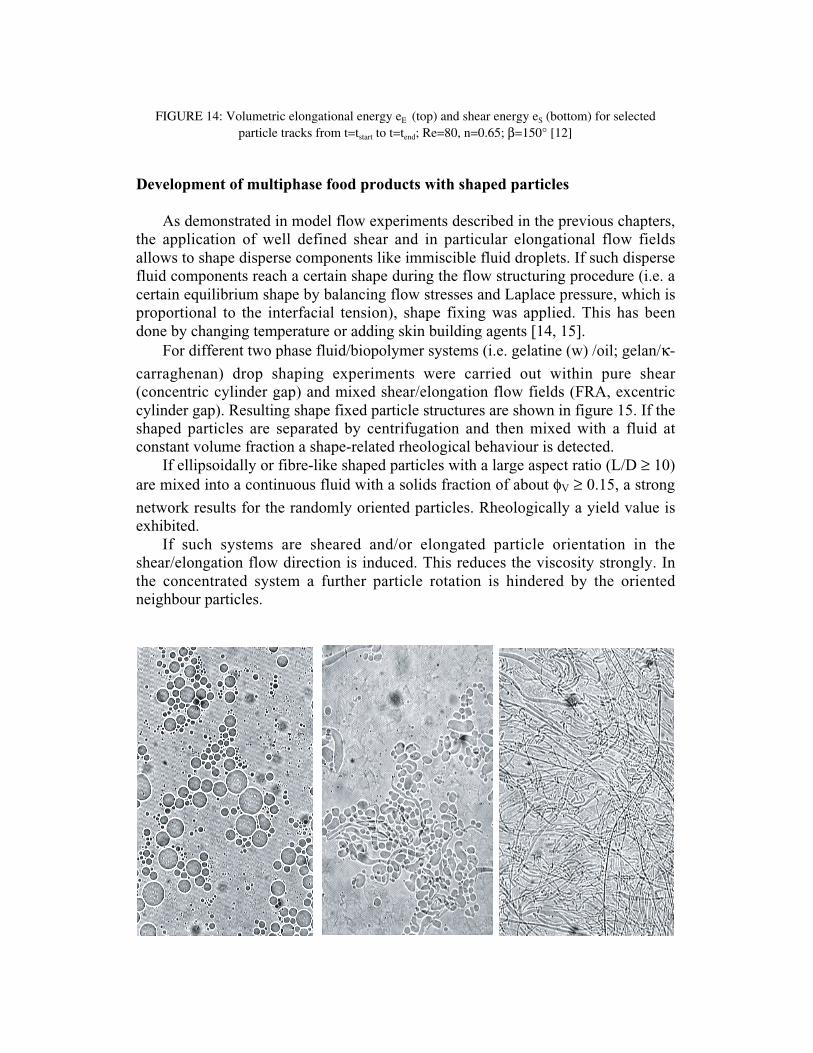
FIGURE 14: Volumetric elongational energy eE (top) and shear energy eS (bottom) for selectedparticle tracks from t=tstart to t=tend; Re=80, n=0.65; β=150° [12]
Development of multiphase food products with shaped particles
As demonstrated in model flow experiments described in the previous chapters,
the application of well defined shear and in particular elongational flow fields
allows to shape disperse components like immiscible fluid droplets. If such disperse
fluid components reach a certain shape during the flow structuring procedure (i.e. a
certain equilibrium shape by balancing flow stresses and Laplace pressure, which is
proportional to the interfacial tension), shape fixing was applied. This has been
done by changing temperature or adding skin building agents [14, 15].
For different two phase fluid/biopolymer systems (i.e. gelatine (w) /oil; gelan/κ-
carraghenan) drop shaping experiments were carried out within pure shear
(concentric cylinder gap) and mixed shear/elongation flow fields (FRA, excentric
cylinder gap). Resulting shape fixed particle structures are shown in figure 15. If the
shaped particles are separated by centrifugation and then mixed with a fluid at
constant volume fraction a shape-related rheological behaviour is detected.
If ellipsoidally or fibre-like shaped particles with a large aspect ratio (L/D ≥ 10)
are mixed into a continuous fluid with a solids fraction of about φV ≥ 0.15, a strong
network results for the randomly oriented particles. Rheologically a yield value is
exhibited.
If such systems are sheared and/or elongated particle orientation in the
shear/elongation flow direction is induced. This reduces the viscosity strongly. In
the concentrated system a further particle rotation is hindered by the oriented
neighbour particles.
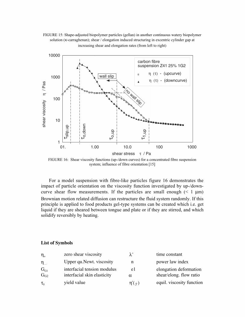
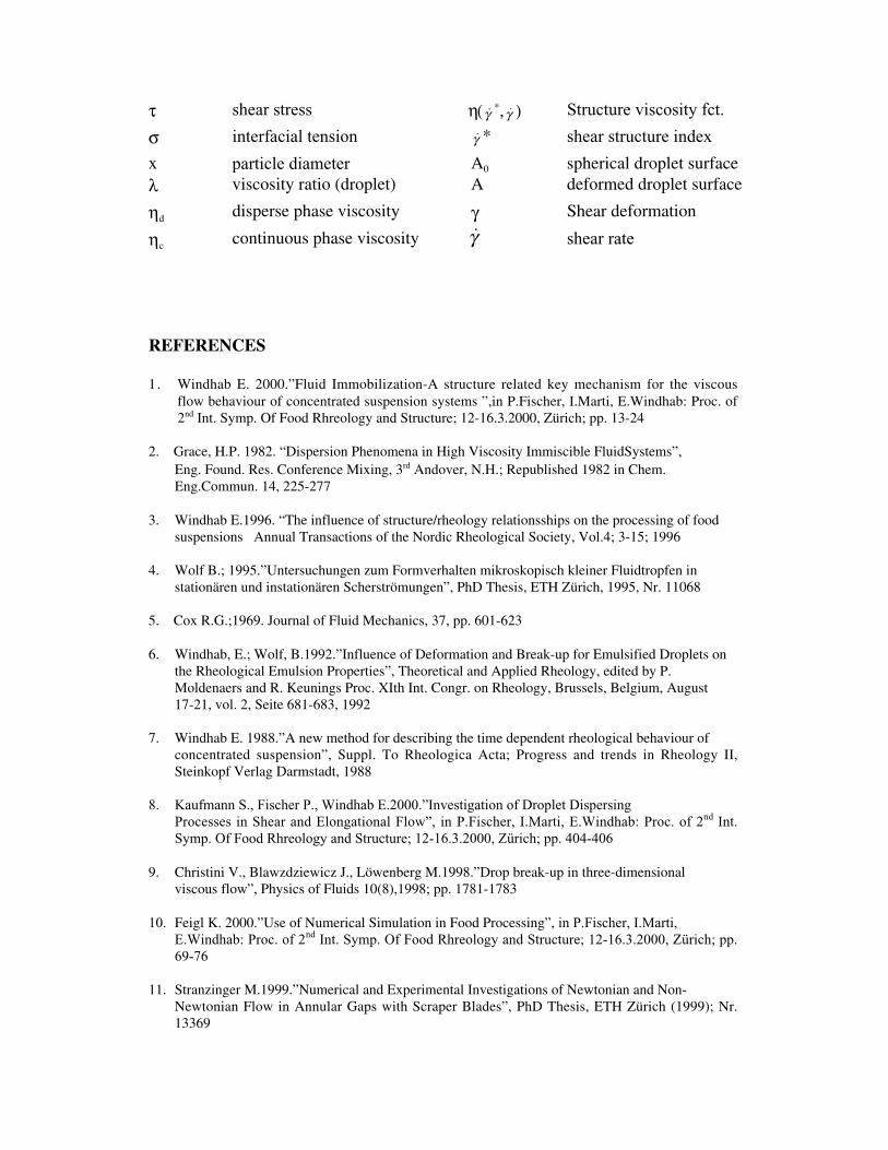
FIGURE 15: Shape-adjusted biopolymer particles (gellan) in another continuous watery biopolymer
solution (κ-carraghenan); shear / elongation induced structuring in excentric cylinder gap at
increasing shear and elongation rates (from left to right)
1
10
100
1000
10000
01. 1.00 10.0 100 1000
η (τ) - (upcurve)
shear stress τ / Pa
shea
r vi
scos
ity
η /
Pas
carbon fibresuspension Z41 25% 1G2
η (τ) - (downcurve)
τ o,u
p
τ o,d
own
τ 1,u
p
τ slip
,up
wall slip
no wall slip
FIGURE 16: Shear viscosity functions (up-/down curves) for a concentrated fibre suspension
system; influence of fibre orientation [15]
For a model suspension with fibre-like particles figure 16 demonstrates the
impact of particle orientation on the viscosity function investigated by up-/down-
curve shear flow measurements. If the particles are small enough (< 1 µm)
Brownian motion related diffusion can restructure the fluid system randomly. If this
principle is applied to food products gel-type systems can be created which i.e. get
liquid if they are sheared between tongue and plate or if they are stirred, and which
solidify reversibly by heating.
List of Symbols
ηo zero shear viscosity λ∗ time constant
η… Upper qu.Newt. viscosity n power law index
GG1 interfacial tension modulus e1 elongation deformation
GG2 interfacial skin elasticity α shear/elong. flow ratio
τ0 yield value η∗( γ̇ ) equil. viscosity function
τ shear stress η(γ̇∗, γ̇ ) Structure viscosity fct.
σ interfacial tension γ̇ * shear structure index
x particle diameter A0 spherical droplet surfaceλ viscosity ratio (droplet) A deformed droplet surface
ηd disperse phase viscosity γ Shear deformation
ηc continuous phase viscosity γ̇ shear rate
REFERENCES
1. Windhab E. 2000.”Fluid Immobilization-A structure related key mechanism for the viscousflow behaviour of concentrated suspension systems ”,in P.Fischer, I.Marti, E.Windhab: Proc. of2nd Int. Symp. Of Food Rhreology and Structure; 12-16.3.2000, Zürich; pp. 13-24
2. Grace, H.P. 1982. “Dispersion Phenomena in High Viscosity Immiscible FluidSystems”, Eng. Found. Res. Conference Mixing, 3rd Andover, N.H.; Republished 1982 in Chem.
Eng.Commun. 14, 225-277
3. Windhab E.1996. “The influence of structure/rheology relationsships on the processing of foodsuspensions Annual Transactions of the Nordic Rheological Society, Vol.4; 3-15; 1996
4. Wolf B.; 1995.”Untersuchungen zum Formverhalten mikroskopisch kleiner Fluidtropfen instationären und instationären Scherströmungen”, PhD Thesis, ETH Zürich, 1995, Nr. 11068
5. Cox R.G.;1969. Journal of Fluid Mechanics, 37, pp. 601-623
6. Windhab, E.; Wolf, B.1992.”Influence of Deformation and Break-up for Emulsified Droplets onthe Rheological Emulsion Properties”, Theoretical and Applied Rheology, edited by P.Moldenaers and R. Keunings Proc. XIth Int. Congr. on Rheology, Brussels, Belgium, August17-21, vol. 2, Seite 681-683, 1992
7. Windhab E. 1988.”A new method for describing the time dependent rheological behaviour ofconcentrated suspension”, Suppl. To Rheologica Acta; Progress and trends in Rheology II,Steinkopf Verlag Darmstadt, 1988
8. Kaufmann S., Fischer P., Windhab E.2000.”Investigation of Droplet Dispersing
Processes in Shear and Elongational Flow”, in P.Fischer, I.Marti, E.Windhab: Proc. of 2nd
Int.
Symp. Of Food Rhreology and Structure; 12-16.3.2000, Zürich; pp. 404-406
9. Christini V., Blawzdziewicz J., Löwenberg M.1998.”Drop break-up in three-dimensionalviscous flow”, Physics of Fluids 10(8),1998; pp. 1781-1783
10. Feigl K. 2000.”Use of Numerical Simulation in Food Processing”, in P.Fischer, I.Marti,
E.Windhab: Proc. of 2nd
Int. Symp. Of Food Rhreology and Structure; 12-16.3.2000, Zürich; pp.
69-76
11. Stranzinger M.1999.”Numerical and Experimental Investigations of Newtonian and Non-Newtonian Flow in Annular Gaps with Scraper Blades”, PhD Thesis, ETH Zürich (1999); Nr.13369
12. Bieder A., Stranzinger M., Windhab E.2000.”Einfluss der Prozessgeometrie auf dasStrukturierungsverhalten in Ringspaltreaktoren”, Semesterwor ETH Zürich 2000
13. Burden R.L., Faires J.D. 1993.”Numerical Analysis, 5th Edition edn. PWS Publishing Company
14. R. Scirocco, B. Wolf, P. Fischer, E. Windhab.2000.”, Diploma Thesis, ETH-Zürich
15. Wolf B. 2000.”Biopolymer Suspensions with Spheroidal and Cylindrical Particle Shapes:
Generation and Flow Behaviour”, in P.Fischer, I.Marti, E.Windhab: Proc. of 2nd
Int. Symp. Of
Food Rhreology and Structure; 12-16.3.2000, Zürich; pp. 404-406
16. Eischen J.C. 1999.”Bildanalytische und rheologische Untersuchungen zum Orientierungs- und
Strukturierungsverhalten von faserförmigen Partikeln in laminaren Scherströmungen”, PhD
Thesis, ETH-Zürich,1999; Nr. 13217
Related Documents