Microprocessor - Based Systems Dr. Randa Elanwar Lecture 9

Welcome message from author
This document is posted to help you gain knowledge. Please leave a comment to let me know what you think about it! Share it to your friends and learn new things together.
Transcript
Microprocessor-Based Systems
Dr. Randa Elanwar
Lecture 9

Lecture Content
• 8086 Interrupts:
– processing
– instructions
• Interrupt priority controller
• Microprocessor-based data communication
2Microprocessor-Based Systems Dr. Randa Elanwar
8086/8088 instruction set (INT)
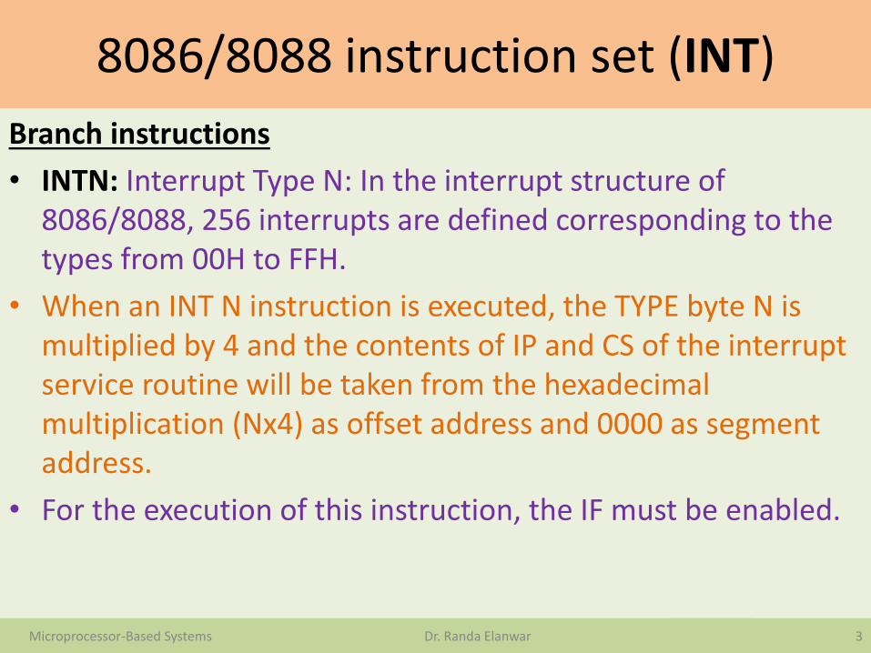
Branch instructions
• INTN: Interrupt Type N: In the interrupt structure of 8086/8088, 256 interrupts are defined corresponding to the types from 00H to FFH.
• When an INT N instruction is executed, the TYPE byte N is multiplied by 4 and the contents of IP and CS of the interrupt service routine will be taken from the hexadecimal multiplication (Nx4) as offset address and 0000 as segment address.
• For the execution of this instruction, the IF must be enabled.
3Microprocessor-Based Systems Dr. Randa Elanwar

8086/8088 instruction set (IRET)
• Branch instructions
• IRET: Return from ISR: When an interrupt service routine is to be called, before transferring control to it, the IP, CS and flag register are stored on to the stack to indicate the location from where the execution is to be continued, after the ISR is executed.
• So, at the end of each ISR, when IRET is executed, the values of IP, CS and flags are retrieved from the stack to continue the execution of the main program. The stack is modified accordingly.
4Microprocessor-Based Systems Dr. Randa Elanwar

Interrupts
5Microprocessor-Based Systems Dr. Randa Elanwar
Control Logic
Creates the addresses
8088 microprocessor
Data bus
Memoryholds data and
instructionsAddress lines
MEMR
MEMW
IOR
IOW
Latch ACSA
I/O decoderExternal
hardware for interrupt
INTINTA
Non maskable interrupt
IFD Q
Interrupts
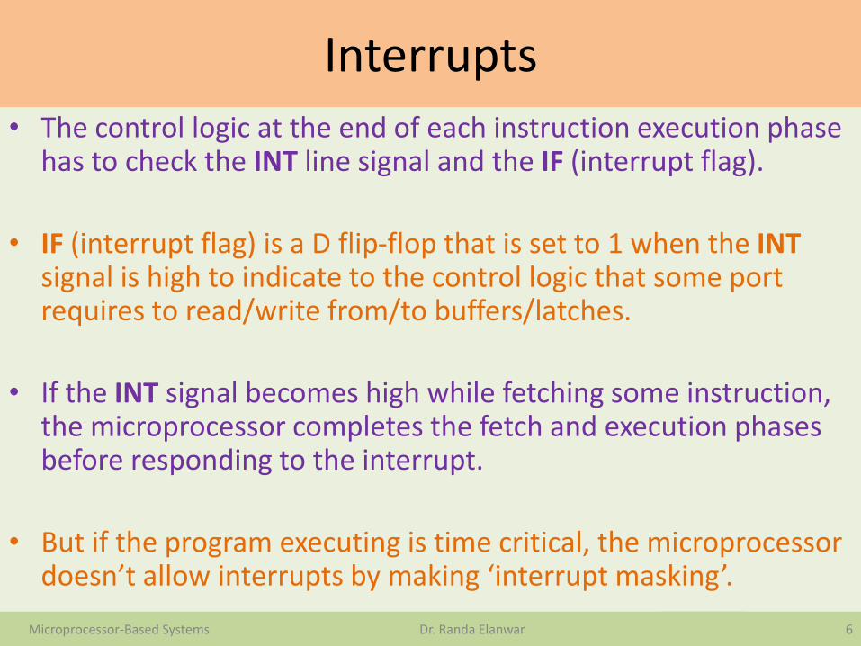
• The control logic at the end of each instruction execution phase has to check the INT line signal and the IF (interrupt flag).
• IF (interrupt flag) is a D flip-flop that is set to 1 when the INTsignal is high to indicate to the control logic that some port requires to read/write from/to buffers/latches.
• If the INT signal becomes high while fetching some instruction, the microprocessor completes the fetch and execution phases before responding to the interrupt.
• But if the program executing is time critical, the microprocessor doesn’t allow interrupts by making ‘interrupt masking’.
6Microprocessor-Based Systems Dr. Randa Elanwar
Interrupts
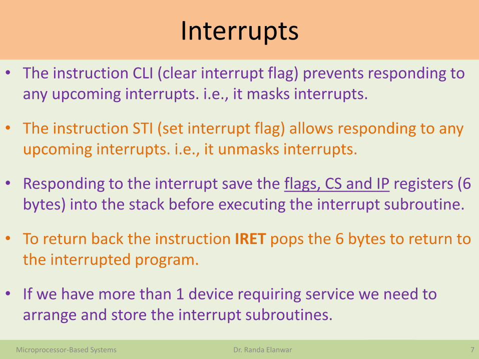
• The instruction CLI (clear interrupt flag) prevents responding to any upcoming interrupts. i.e., it masks interrupts.
• The instruction STI (set interrupt flag) allows responding to any upcoming interrupts. i.e., it unmasks interrupts.
• Responding to the interrupt save the flags, CS and IP registers (6 bytes) into the stack before executing the interrupt subroutine.
• To return back the instruction IRET pops the 6 bytes to return to the interrupted program.
• If we have more than 1 device requiring service we need to arrange and store the interrupt subroutines.
7Microprocessor-Based Systems Dr. Randa Elanwar

Interrupts
• If the interrupt pin INT goes high and the interrupt flag is set, at the end of execution phase of the current instruction , the microprocessor will:
1. Push flags onto the stack flagsH then flagsL.
2. Clear the interrupt flag and the trap flag.
3. Push CS and IP into the stack CSH then CSL then IPH then IPL.
4. Output 2 interrupt acknowledge cycles, the external interrupts handling hardware should output 1 byte on the data bus representing the interrupt number ‘n’.
5. Reads from the external memory (4 MEMR signals):
0000:4n IPL 0000:4n+1 IPH
0000:4n+2 CSL 0000:4n+3 CSH8Microprocessor-Based Systems Dr. Randa Elanwar

Interrupts
9Microprocessor-Based Systems Dr. Randa Elanwar
•The interrupt vector table is the located on the top of the memory (segment 0000).
•Each 4 bytes represent the information required for ISR execution (CS and IP)
•The interrupt vector table holds up to 256 interrupt vectors
•I.e., 0<= n <=255
0000:0000 ----------1 ---------2 --------- INT 03 ---------4 ---------5 --------- INT 16 ---------7 ---------8 ---------9 --------- INT 2A ----------B ---------C ---------D --------- INT 3E ---------
F --------------------------- INT 255Interrupt vector table
Interrupts
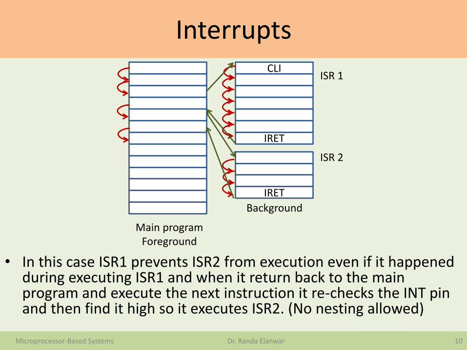
• In this case ISR1 prevents ISR2 from execution even if it happened during executing ISR1 and when it return back to the main program and execute the next instruction it re-checks the INT pin and then find it high so it executes ISR2. (No nesting allowed)
10Microprocessor-Based Systems Dr. Randa Elanwar
IRET
CLI
IRET
Main programForeground
ISR 1
ISR 2
Background
Interrupts
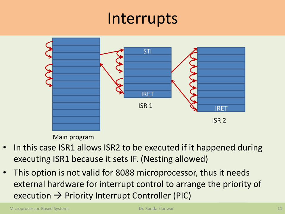
• In this case ISR1 allows ISR2 to be executed if it happened during executing ISR1 because it sets IF. (Nesting allowed)
• This option is not valid for 8088 microprocessor, thus it needs external hardware for interrupt control to arrange the priority of execution Priority Interrupt Controller (PIC)
11Microprocessor-Based Systems Dr. Randa Elanwar
IRET
STI
IRET
Main program
ISR 1
ISR 2

Priority Interrupt Controller
• Complex integrated circuit that helps in interfacing a microprocessor to a set of external devices requesting services upon an interrupt. The PIC:
1. Accepts interrupts from 8 devices and stores them in IRQ register.
2. If there is an IRQ, it raises the INT pin high and waits for INTA (acknowledge)
3. Upon receiving INTA, it puts the interrupt number (n) on the data bus.
4. It allows for masking devices selectively.
5. If there is more than one IRQ it resolves the priority problem and outputs INT signal. When receiving INTA it puts (n) of the highest priority on the data bus. (Note: the microprocessor is free to accept it or not)
12Microprocessor-Based Systems Dr. Randa Elanwar

Priority Interrupt Controller
13Microprocessor-Based Systems Dr. Randa Elanwar
Memory(has 256
INT)
I/O decoder
L L
LPIC
External device
External device
microprocessor
IRQ0
IRQ7
.
.
.
.
……
A0
A19
A0
A9
MEMR
MEMW
IOR
IOW
INTINTA
NMI
IOR
IOW
A0
A1
CS

Microprocessor-based data communication
• Within a microcomputer data is transferred in parallel because that is the fastest way to do it.
• For transferring data over long distances, parallel data transmission require too many wires. Therefore, data to be sent is converted from parallel to serial form and transmitted serially on a single or a pair of wires.
• The received serial data is re-converted to parallel to be easily transferred on the micro-computer buses.
• Serial data systems are either: simplex, half-duplex, and full-duplex.
• A simplex data line can transmit data only in one direction.• Half duplex transmission means that communication can take
place in either direction between two systems, but can only occur in one direction.
14Microprocessor-Based Systems Dr. Randa Elanwar

Microprocessor-based data communication
• Full duplex means that each system can send and receive data at the same time.
• Serial data can be sent synchoronously or asynchoronously.
• For synchoronous transmission, data is sent in blocks at a constant rate. The start and end of a block are identified with specific bytes or bit patterns.
• For asynchoronous transmission, each data character has a bit which identifies its start and 1 or 2 bits which identify its end. Characters can be sent at any time (asynchoronously).
• To interface a microcomputer with serial data lines, the data must be converted to and from serial form. A parallel-in-serial-out shift register and a serial-in-parallel-out shift register can be used to do this.
15Microprocessor-Based Systems Dr. Randa Elanwar

Microprocessor-based data communication
• A handshaking circuitry is needed for some cases of serial data transfer to make sure that a transmitter does not send data faster than it can be read in by the receiving system.
• The interface device which can only do asynchoronouscommunication is referred to as universal asynchoronousreceiver-transmitter ‘UART’.
• The interface device which can only do either synchoronousor asynchoronous communication is referred to as universal synchoronous-asynchoronous receiver-transmitter ‘USART’.
• Modems are used to send serial data over long distances are known as data communication equipment ‘DCE’. The terminals/computers that are sending or receiving serial data are referred to as data terminal equipment ‘DTE’.
16Microprocessor-Based Systems Dr. Randa Elanwar

Microprocessor-based data communication
17Microprocessor-Based Systems Dr. Randa Elanwar
DTEDTEDCEDCE
TxDRxD
RTS
CTS
CD
DTR
DSR
Computer
Modem
TxDRxD
RTS
CTS
CD
DTR
DSR
Computer
Modem
Telephone line
After the terminal power is turned on , it send a data-terminal-ready DTR signal to tell the modem it is ready.
When it is powered up and ready to transmit and receive data, the modem will send the data-set-ready DSR signal to the terminal, the modem then dials up the computer.
If the computer is available it will send back a specified acknowledgement.

Microprocessor-based data communication
18Microprocessor-Based Systems Dr. Randa Elanwar
DTEDTEDCEDCE
TxDRxD
RTS
CTS
CD
DTR
DSR
Computer
Modem
TxDRxD
RTS
CTS
CD
DTR
DSR
Computer
Modem
Telephone line
When the terminal has a character actually ready to send it will send Request-to-send RTSsignal to the modem.
The modem will then send its carrier-detect CD signal back to the terminal to indicate it has established contact with the computer.
When the modem is fully ready to transmit it sends clear-to-send CTS signal back to the terminal.

Microprocessor-based data communication
19Microprocessor-Based Systems Dr. Randa Elanwar
DTEDTEDCEDCE
TxDRxD
RTS
CTS
CD
DTR
DSR
Computer
Modem
TxDRxD
RTS
CTS
CD
DTR
DSR
Computer
Modem
Telephone line
The terminal then sends serial data characters to the modem.
When the terminal has sent all the characters it needs to, it makes its RTS signal high. This causes the modem to cut the CTS signal and stop transmission.
A similar handshake occurs between the modem and the computer at the other end of the data link.

Microprocessor-based data communication
• The data and handshake signal names are part of a serial data communication standards called RS-232C.
• This standard describes the function of 25 signal and handshake pins for serial data transfer.
20Microprocessor-Based Systems Dr. Randa Elanwar

Microprocessor-based data communication
The serial communication between PC-A and PC-B through input/output interface
21Microprocessor-Based Systems Dr. Randa Elanwar
PC-A (sends) PC-B (receives)
1. Set memory pointers 1. Set memory pointers
2. Enable transmission 2. Enable reception
3. Set Strobe (Request) signal low 3. Set Acknowledge signal low
4. Wait for Acknowledge signal low 4. Wait for Strobe signal high
5. Output byte and increment pointer 5. Read byte and store
6. Set Strobe signal high 6. Set Acknowledge signal high
7. Wait for Acknowledge signal high 7. Wait for Strobe signal low
8. Check if transmission complete 8. Set Acknowledge signal low
9. If not go to step 5 9. Check if reception complete
10. If Yes – Exit program 10. If not go to step 4
11. If Yes – Exit program

Microprocessor-based data communicationMOV AX, 3000MOV DS, AXMOV SI, 0000MOV DX, 37AIN AL, DXAND AL, DEOUT DX, ALMOV DX, 379IN AL, DXAND AL, 08JNZLODSBMOV DX, 378OUT DX, ALMOV DX, 37AIN AL, DXOR AL, 01OUT DX, AL
22Microprocessor-Based Systems Dr. Randa Elanwar
Set memory pointers
Enable transmission and set Strobe low
Wait for Acknowledge low
Output byte and increment pointer
Set Strobe high
Related Documents