© March 15, 2008 Dr. Lynn Fuller, Motorola Professor Rochester Institute of Technology Microelectronic Engineering MEMS Electrical Fundamentals Page 1 ROCHESTER INSTITUTE OF TEHNOLOGY MICROELECTRONIC ENGINEERING 3-15-2008 mem_elec.ppt Microelectromechanical Systems (MEMs) Electrical Fundamentals Dr. Lynn Fuller Webpage: http://people.rit.edu/lffeee Microelectronic Engineering Rochester Institute of Technology 82 Lomb Memorial Drive Rochester, NY 14623-5604 Tel (585) 475-2035 Fax (585) 475-5041 Email: [email protected] Department webpage: http://www.microe.rit.edu

Welcome message from author
This document is posted to help you gain knowledge. Please leave a comment to let me know what you think about it! Share it to your friends and learn new things together.
Transcript

© March 15, 2008 Dr. Lynn Fuller, Motorola Professor
Rochester Institute of TechnologyMicroelectronic Engineering
MEMS Electrical Fundamentals
Page 1
ROCHESTER INSTITUTE OF TEHNOLOGYMICROELECTRONIC ENGINEERING
3-15-2008 mem_elec.ppt
Microelectromechanical Systems (MEMs)Electrical Fundamentals
Dr. Lynn FullerWebpage: http://people.rit.edu/lffeee
Microelectronic EngineeringRochester Institute of Technology
82 Lomb Memorial DriveRochester, NY 14623-5604
Tel (585) 475-2035Fax (585) 475-5041
Email: [email protected] webpage: http://www.microe.rit.edu
© March 15, 2008 Dr. Lynn Fuller, Motorola Professor
Rochester Institute of TechnologyMicroelectronic Engineering
MEMS Electrical Fundamentals
Page 2
OUTLINE
ResistorsHeatersTemperature SensorsCapacitorsElectrostatic ForceGap Comb DrivesMagnetic ActuatorsPiezoelectric DevicesDiode Temperature SensorsPhotodiodeSeeback EffectPeltier EffectTunnel Sensors

© March 15, 2008 Dr. Lynn Fuller, Motorola Professor
Rochester Institute of TechnologyMicroelectronic Engineering
MEMS Electrical Fundamentals
Page 3
INTRODUCTION
Resistors are used as heaters, temperature sensors, piezoreistorsensors and photoconductors. Heaters are used in many MEMS applications including ink jet print heads, actuators, bio-mems, chemical detectors and gas flow sensors. Diodes, Capacitors, electrostatic comb drives, magnetic devices, and many other devices are used in many applications. This module will discuss these devices as they apply to MEMS.
© March 15, 2008 Dr. Lynn Fuller, Motorola Professor
Rochester Institute of TechnologyMicroelectronic Engineering
MEMS Electrical Fundamentals
Page 4
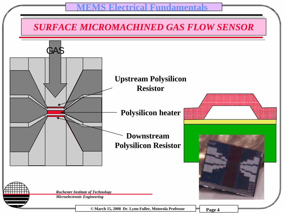
SURFACE MICROMACHINED GAS FLOW SENSOR
Upstream Polysilicon Resistor
Polysilicon heater
Downstream Polysilicon Resistor
GAS

© March 15, 2008 Dr. Lynn Fuller, Motorola Professor
Rochester Institute of TechnologyMicroelectronic Engineering
MEMS Electrical Fundamentals
Page 5
SURFACE MICROMACHINED GAS FLOW SENSOR
Vee Chee Hwang, 2004
© March 15, 2008 Dr. Lynn Fuller, Motorola Professor
Rochester Institute of TechnologyMicroelectronic Engineering
MEMS Electrical Fundamentals
Page 6
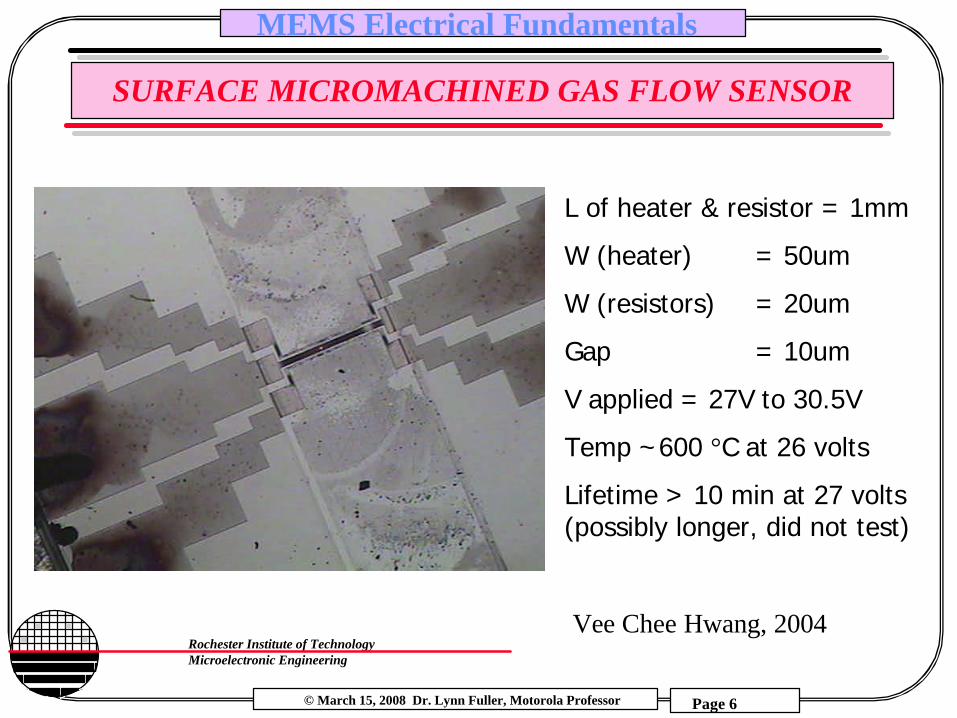
SURFACE MICROMACHINED GAS FLOW SENSOR
L of heater & resistor = 1mm
W (heater) = 50um
W (resistors) = 20um
Gap = 10um
V applied = 27V to 30.5V
Temp ~600 °C at 26 volts
Lifetime > 10 min at 27 volts (possibly longer, did not test)
Vee Chee Hwang, 2004

© March 15, 2008 Dr. Lynn Fuller, Motorola Professor
Rochester Institute of TechnologyMicroelectronic Engineering
MEMS Electrical Fundamentals
Page 7
BULK MICROMACHINED GAS FLOW SENSOR
Measured Resistance, V/I=1.2KohmsTheoretical Resistance, L*Rhos/W= 400µm*60/20µm = 1.2Kohms
Raunak Mann, 2004

© March 15, 2008 Dr. Lynn Fuller, Motorola Professor
Rochester Institute of TechnologyMicroelectronic Engineering
MEMS Electrical Fundamentals
Page 8
THERMIONIC GAS DETECTOR
§ Polysilicon Micro-filament heater
ResistiveHeater
Ioniccurrent
BiasingPlate
CollectionPlate
AmplifiedCurrent
Make hotThermionic emission occurs causing ionizationForce ions to a collection plateMeasure resulting current or voltage
+
-
Robert Manley, 2004

© March 15, 2008 Dr. Lynn Fuller, Motorola Professor
Rochester Institute of TechnologyMicroelectronic Engineering
MEMS Electrical Fundamentals
Page 9
THERMIONIC GAS DETECTOR
Si
Polysilicon
Silicon Nitride
Un-etchedSacox
Robert Manley, 2004

© March 15, 2008 Dr. Lynn Fuller, Motorola Professor
Rochester Institute of TechnologyMicroelectronic Engineering
MEMS Electrical Fundamentals
Page 10
THERMIONIC GAS DETECTOR
Cold Hot
Robert Manley, 2004

© March 15, 2008 Dr. Lynn Fuller, Motorola Professor
Rochester Institute of TechnologyMicroelectronic Engineering
MEMS Electrical Fundamentals
Page 11
OHMS LAW
I
V
Resistor a two terminal device that exhibits a linear I-V characteristic that goes through the origin. The inverse slope is the value of the resistance.
R = V/I = 1/slope
I
V
-
+

© March 15, 2008 Dr. Lynn Fuller, Motorola Professor
Rochester Institute of TechnologyMicroelectronic Engineering
MEMS Electrical Fundamentals
Page 12
THE SEMICONDUCTOR RESISTOR
Resistance = R = ρ L/Area = ρs L/w ohms
Resistivity = Rho = ρ = 1/( qµnn + qµpp) ohm-cm
Sheet Resistance = Rhos = ρs = 1/ ( q µ(N) N(x) dx) ~ 1/( qµ Dose) ohms/square
L Area
R
wt
ρs = ρ / t
Note: sheet resistance is convenient to use when the resistors are made of thin sheet of material, like in integrated circuits.
R = Rho L / Area= Rhos L/W
Rho is the bulk resistivity of the material (ohm-cm)Rhos is the sheet resistance (ohm/sq) = Rho / t
© March 15, 2008 Dr. Lynn Fuller, Motorola Professor
Rochester Institute of TechnologyMicroelectronic Engineering
MEMS Electrical Fundamentals
Page 13
MOBILITY
Total Impurity Concentration (cm-3)
0200400600800
1000120014001600
1013
1014
1015
1016
1017
1018
1019
1020
ArsenicBoronPhosphorus
Mob
ility
(cm
2 / V
sec
)
electrons
holes
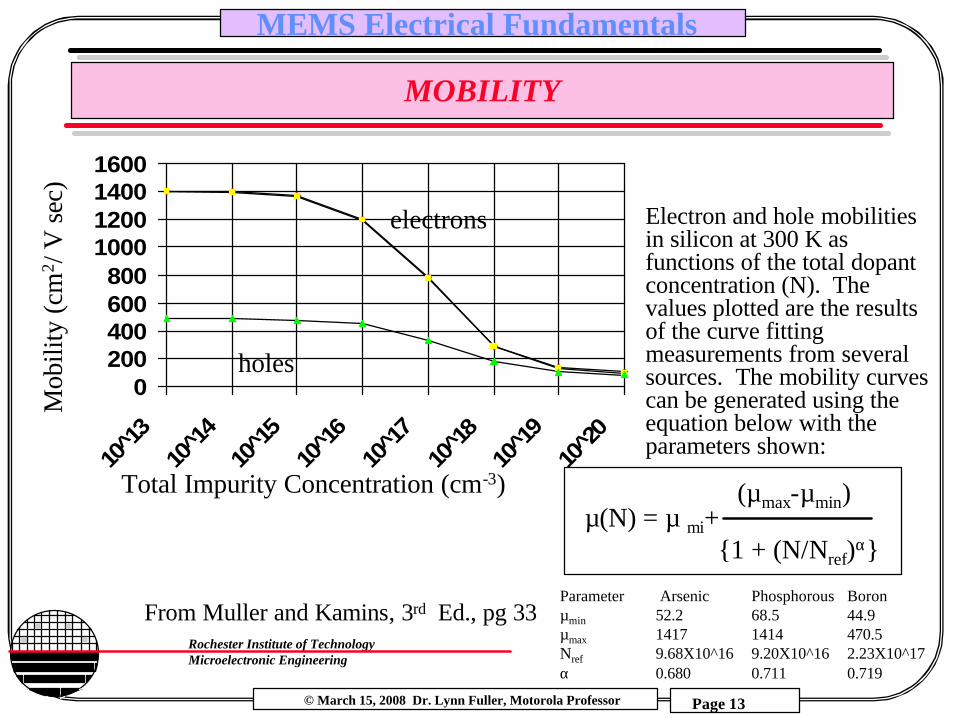
Parameter Arsenic Phosphorous Boronµmin 52.2 68.5 44.9µmax 1417 1414 470.5Nref 9.68X10^16 9.20X10^16 2.23X10^17α 0.680 0.711 0.719
µ(N) = µ mi+ (µmax-µmin)
1 + (N/Nref)α
Electron and hole mobilitiesin silicon at 300 K as functions of the total dopantconcentration (N). The values plotted are the results of the curve fitting measurements from several sources. The mobility curves can be generated using the equation below with the parameters shown:
From Muller and Kamins, 3rd Ed., pg 33
© March 15, 2008 Dr. Lynn Fuller, Motorola Professor
Rochester Institute of TechnologyMicroelectronic Engineering
MEMS Electrical Fundamentals
Page 14
TEMPERATURE EFFECTS ON MOBILITY
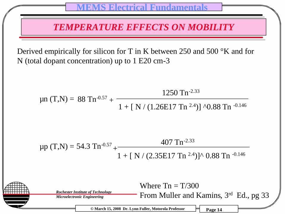
Derived empirically for silicon for T in K between 250 and 500 °K and for N (total dopant concentration) up to 1 E20 cm-3
µn (T,N) =
µp (T,N) =
88 Tn-0.57
54.3 Tn-0.57
Where Tn = T/300From Muller and Kamins, 3rd Ed., pg 33
1250 Tn-2.33
407 Tn-2.33
1 + [ N / (1.26E17 Tn 2.4)] ^0.88 Tn -0.146
1 + [ N / (2.35E17 Tn 2.4)]^ 0.88 Tn -0.146
+
+

© March 15, 2008 Dr. Lynn Fuller, Motorola Professor
Rochester Institute of TechnologyMicroelectronic Engineering
MEMS Electrical Fundamentals
Page 15
EXCELL WORKSHEET TO CALCULATE MOBILITY
MICROELECTRONIC ENGINEERING 3/13/2005
CALCULATION OF MOBILITY Dr. Lynn Fuller
To use this spreadsheed change the values in the white boxes. The rest of the sheet isprotected and should not be changed unless you are sure of the consequences. Thecalculated results are shown in the purple boxes.
CONSTANTS VARIABLES CHOICESTn = T/300 = 1.22 1=yes, 0=no
Temp= 365 °K n-type 1N total 1.00E+18 cm-3 p-type 0
<100>
Kamins, Muller and Chan; 3rd Ed., 2003, pg 33mobility= 163 cm2/(V-sec)

© March 15, 2008 Dr. Lynn Fuller, Motorola Professor
Rochester Institute of TechnologyMicroelectronic Engineering
MEMS Electrical Fundamentals
Page 16
EXCELL WORKSHEET TO CALCULATE RESISTANCE
MICROELECTRONIC ENGINEERING 7/23/2007Rochester Institute of Technology Dr. Lynn Fuller
CALCULATION OF RESISTANCE FROM LENGTH, WIDTH, THICKNESS AND IMPLANT DOSE
To use this spreadsheed change the values in the white boxes. The rest of the sheet isprotected and should not be changed unless you are sure of the consequences. Thecalculated results are shown in the purple boxes.
Calculation of Mobility
CONSTANTS VARIABLES CHOICESTn = T/300 =1.00 1=yes, 0=no
Temp= 300 °K n-type 0N total 2.00E+16 cm-3 p-type 1
<100>
Kamins, Muller and Chan; 3rd Ed., 2003, pg 33mobility = µ = 433 cm2/(V-sec)
Calculation of ResistanceLength, L = 6000 µm
R = Rho L / W / t Width, W = 20 µmR = Rhos L / W Thickness, t = 0.5 µm
Implant Dose = 1.00E+12 ions/cm2Rho = bulk resistivityRhos = sheet resistance =1/(q µ Dose) N total = Average Doping = 2.00E+16 atoms/cm3
q = 1.6e-19 coul/ion Mobility, µ = 433 cm2/v-secResistance = 1.73E+09 ohms

© March 15, 2008 Dr. Lynn Fuller, Motorola Professor
Rochester Institute of TechnologyMicroelectronic Engineering
MEMS Electrical Fundamentals
Page 17
TEMPERATURE COEFFICIENT OF RESISTANCE
∆R/∆T for semiconductor resistors
R = Rhos L/W = Rho/t L/W
assume W, L, t do not change with T
Rho = 1/(qµn + qµp) where µ is the mobility which is a function of temperature, n and p are the carrier concentrations which can be a function of temperature (in lightly doped semiconductors)
as T increases, µ decreases, n or p may increase and the result is that R usually increases unless the decrease in µ is cancelled by the increase in n or p
© March 15, 2008 Dr. Lynn Fuller, Motorola Professor
Rochester Institute of TechnologyMicroelectronic Engineering
MEMS Electrical Fundamentals
Page 18
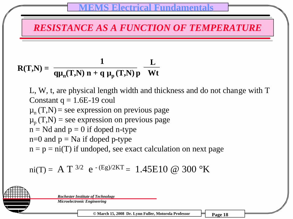
RESISTANCE AS A FUNCTION OF TEMPERATURE
R(T,N) = 1
qµn(T,N) n + q µp (T,N) pL
Wt
L, W, t, are physical length width and thickness and do not change with TConstant q = 1.6E-19 coulµn (T,N) = see expression on previous pageµp (T,N) = see expression on previous pagen = Nd and p = 0 if doped n-typen=0 and p = Na if doped p-typen = p = ni(T) if undoped, see exact calculation on next page
ni(T) = A T 3/2 e - (Eg)/2KT = 1.45E10 @ 300 °K

© March 15, 2008 Dr. Lynn Fuller, Motorola Professor
Rochester Institute of TechnologyMicroelectronic Engineering
MEMS Electrical Fundamentals
Page 19
EXACT CALCULATION OF n AND p
CONSTANTS VARIABLESK 1.38E-23 J/Kq 1.60E-19 CoulEgo 1.16 eVa 7.02E-04B 1.11E+03h 6.63E-34 Jsec Nd = 3.00E+16 cm-3 Donor Concentrationεo 8.85E-14 F/cm Ed= 0.049 eV below Ecεr 11.7 Na = 8.00E+15 cm-3 Acceptor Concentrationni 1.45E+10 cm-3 Ea= 0.045 eV above EvNc/T^3/2 5.43E+15Nv/T^3/2 2.02E+15 Temp= 300 °K
Donor and Acceptor Levels (eV above or below Ev or Ec)Boron 0.044
Phosphorous 0.045Arsenic 0.049
CALCULATIONS: (this program makes a guess at the value of the fermi level and trys to minimizethe charge balance)
KT/q 0.026 VoltsEg=Ego-(aT^2/(T+B)) 1.115 eVNc 2.82E+19 cm-3Nv 1.34E+01 cm-3Fermi Level, Ef 0.9295 eV above Evfree electrons, n = Nc exp(-q(Ec-Ef)KT) 2.17E+16 cm-3Ionized donors, Nd+ = Nd*(1+2*exp(q(Ef-Ed)/KT))^(-1) 2.97E+16 cm-3holes, p = Nv exp(-q(Ef-Ev)KT) 3.43E-15 cm-3Ionized acceptors, Na- = Na*(1+2*exp(q(Ea-Ef)/KT))^(-1) 8.00E+15 cm-3Charge Balance = p + Nd+ - n - Na- 3.22E+12 cm-3
Click on Button to do Calculation
ButtonButton
© March 15, 2008 Dr. Lynn Fuller, Motorola Professor
Rochester Institute of TechnologyMicroelectronic Engineering
MEMS Electrical Fundamentals
Page 20
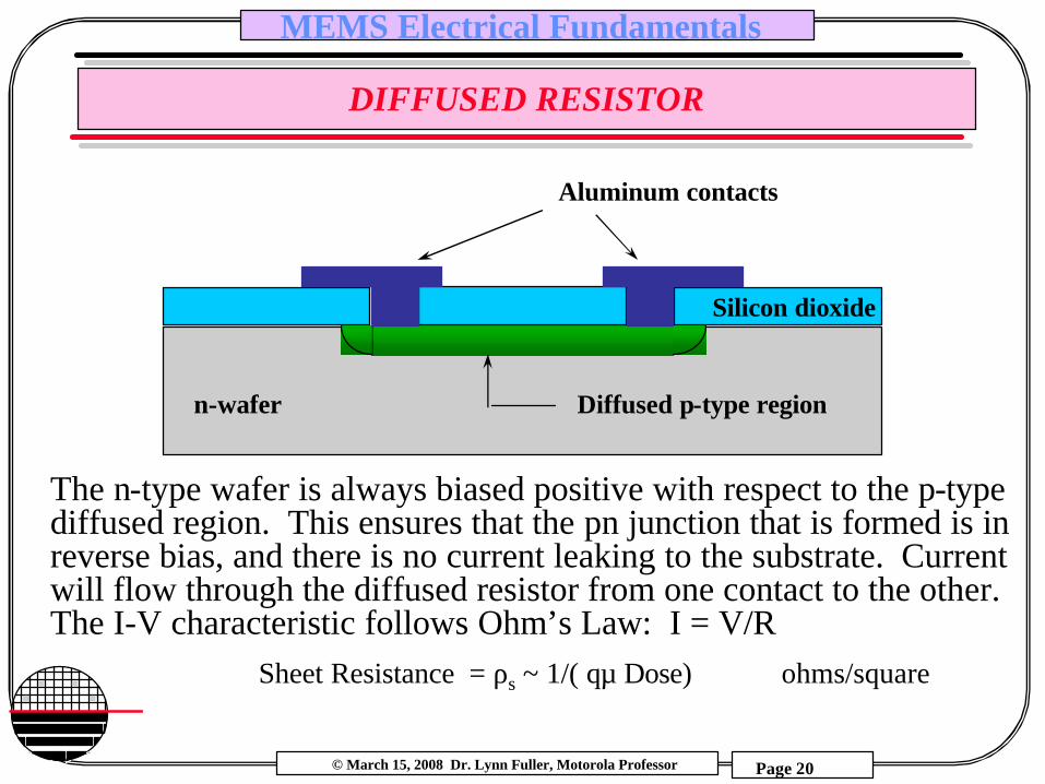
DIFFUSED RESISTOR
Aluminum contacts
The n-type wafer is always biased positive with respect to the p-type diffused region. This ensures that the pn junction that is formed is in reverse bias, and there is no current leaking to the substrate. Current will flow through the diffused resistor from one contact to the other. The I-V characteristic follows Ohm’s Law: I = V/R
n-wafer Diffused p-type region
Silicon dioxide
Sheet Resistance = ρs ~ 1/( qµ Dose) ohms/square
© March 15, 2008 Dr. Lynn Fuller, Motorola Professor
Rochester Institute of TechnologyMicroelectronic Engineering
MEMS Electrical Fundamentals
Page 21
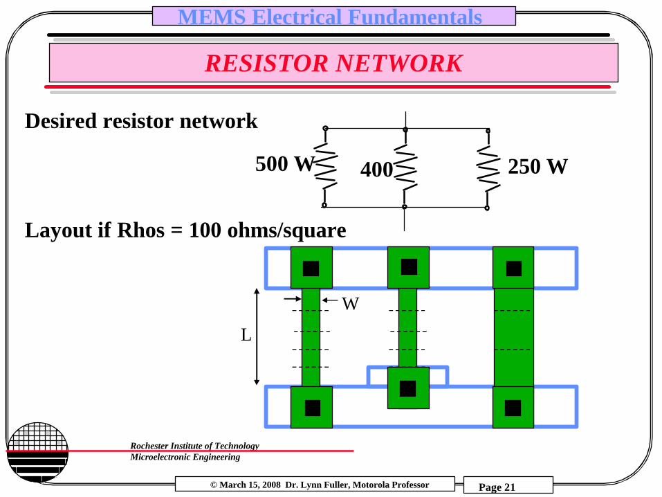
RESISTOR NETWORK
500 Ω 400 250 Ω
Desired resistor network
Layout if Rhos = 100 ohms/square
L
W
© March 15, 2008 Dr. Lynn Fuller, Motorola Professor
Rochester Institute of TechnologyMicroelectronic Engineering
MEMS Electrical Fundamentals
Page 22
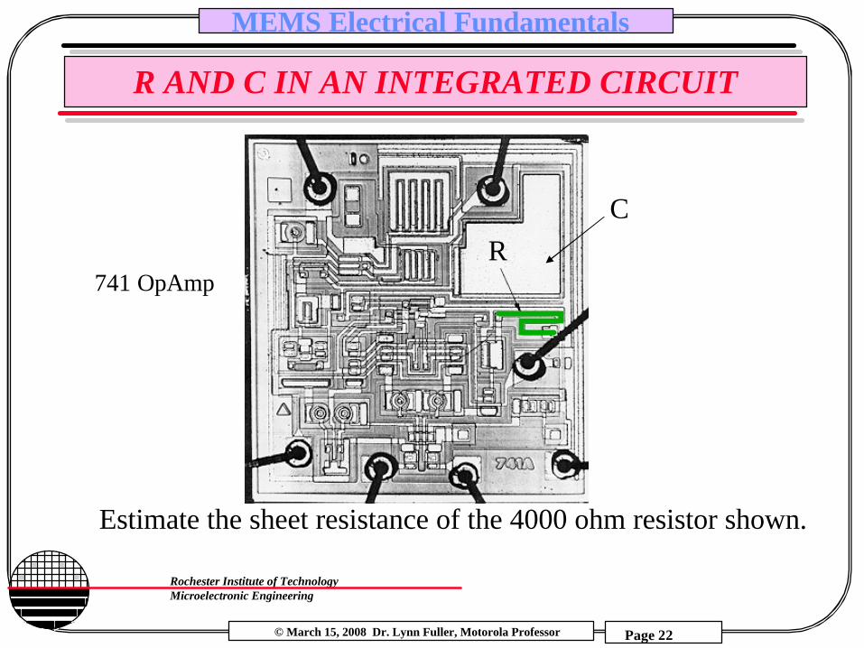
R AND C IN AN INTEGRATED CIRCUIT
Estimate the sheet resistance of the 4000 ohm resistor shown.
RC
741 OpAmp

© March 15, 2008 Dr. Lynn Fuller, Motorola Professor
Rochester Institute of TechnologyMicroelectronic Engineering
MEMS Electrical Fundamentals
Page 23
DIFFUSION FROM A CONSTANT SOURCE
N(x,t) = No erfc (x/2 Dptp)
SolidSolubilityLimit, No
xinto wafer
Wafer Background Concentration, NBC
N(x,t)
Xj
p-type
n-type
erfc function

© March 15, 2008 Dr. Lynn Fuller, Motorola Professor
Rochester Institute of TechnologyMicroelectronic Engineering
MEMS Electrical Fundamentals
Page 24
DIFFUSION FROM A LIMITED SOURCE
for erfc predepositQ’A (tp) = QA(tp)/Area = 2 No (Dptp) / π = Dose
N(x,t) = Q’A(tp) Exp (- x2/4Dt)π Dt
Where D is the diffusion constant at the drive in temperature and t is the drive in diffusion time, Dp is the diffusion constant at the predeposit temperature and tp is the predeposit time
Gaussian function

© March 15, 2008 Dr. Lynn Fuller, Motorola Professor
Rochester Institute of TechnologyMicroelectronic Engineering
MEMS Electrical Fundamentals
Page 25
DIFFUSION CONSTANTS AND SOLID SOLUBILITY
DIFFUSION CONSTANTSBORON PHOSPHOROUS BORON PHOSPHOROUS
TEMP PRE or DRIVE-IN PRE DRIVE-IN SOLID SOLIDSOLUBILITY SOLUBILITY
NOB NOP900 °C 1.07E-15 cm2/s 2.09e-14 cm2/s 7.49E-16 cm2/s 4.75E20 cm-3 6.75E20 cm-3950 4.32E-15 6.11E-14 3.29E-15 4.65E20 7.97E201000 1.57E-14 1.65E-13 1.28E-14 4.825E20 9.200E201050 5.15E-14 4.11E-13 4.52E-14 5.000E20 1.043E211100 1.55E-13 9.61E-13 1.46E-13 5.175E20 1.165E211150 4.34E-13 2.12E-12 4.31E-13 5.350E20 1.288E211200 1.13E-12 4.42E-12 1.19E-12 5.525E20 1.410E211250 2.76E-12 8.78E-12 3.65E-12 5.700E20 1.533E21
DpDp or D D

© March 15, 2008 Dr. Lynn Fuller, Motorola Professor
Rochester Institute of TechnologyMicroelectronic Engineering
MEMS Electrical Fundamentals
Page 26
ION IMPLANTED RESISTOR
Like the diffused resistor but more accurate control over the sheet resistance. The dose is a machine parameter that is set by the user.
Sheet Resistance = ρs ~ 1/( qµ Dose) ohms/square
Also the dose can be lower than in a diffused resistor resulting in higher sheet resistance than possible with the diffused resistor.
Aluminum contacts
n-wafer Ion Implanted p-type region
Silicon dioxide

© March 15, 2008 Dr. Lynn Fuller, Motorola Professor
Rochester Institute of TechnologyMicroelectronic Engineering
MEMS Electrical Fundamentals
Page 27
THIN FILM RESISTOR
Aluminum contacts
n-wafer Thin Layer of Poly SiliconOr Metal
Silicon dioxide
For polysilicon thin films the Dose = film thickness ,t, x Solid Solubility No if doped by diffusion, or Dose = ion implanter dose setting if implanted
The Sheet Resistance Rhos = ~ 1/( qµ Dose) ohms/square
For metal the Sheet Resistance is ~ the given (table value) of bulk resistivity, Rho, divided by the film thickness ,t.
Rhos = Rho / t ohms/square

© March 15, 2008 Dr. Lynn Fuller, Motorola Professor
Rochester Institute of TechnologyMicroelectronic Engineering
MEMS Electrical Fundamentals
Page 28
HEATERS
P= IV = I2R watts
Final steady state temperaturedepends on power density inwatts/cm2
and
the thermal resistancefrom heater to ambient
I
V
-
+
R = ρs L/W
© March 15, 2008 Dr. Lynn Fuller, Motorola Professor
Rochester Institute of TechnologyMicroelectronic Engineering
MEMS Electrical Fundamentals
Page 29
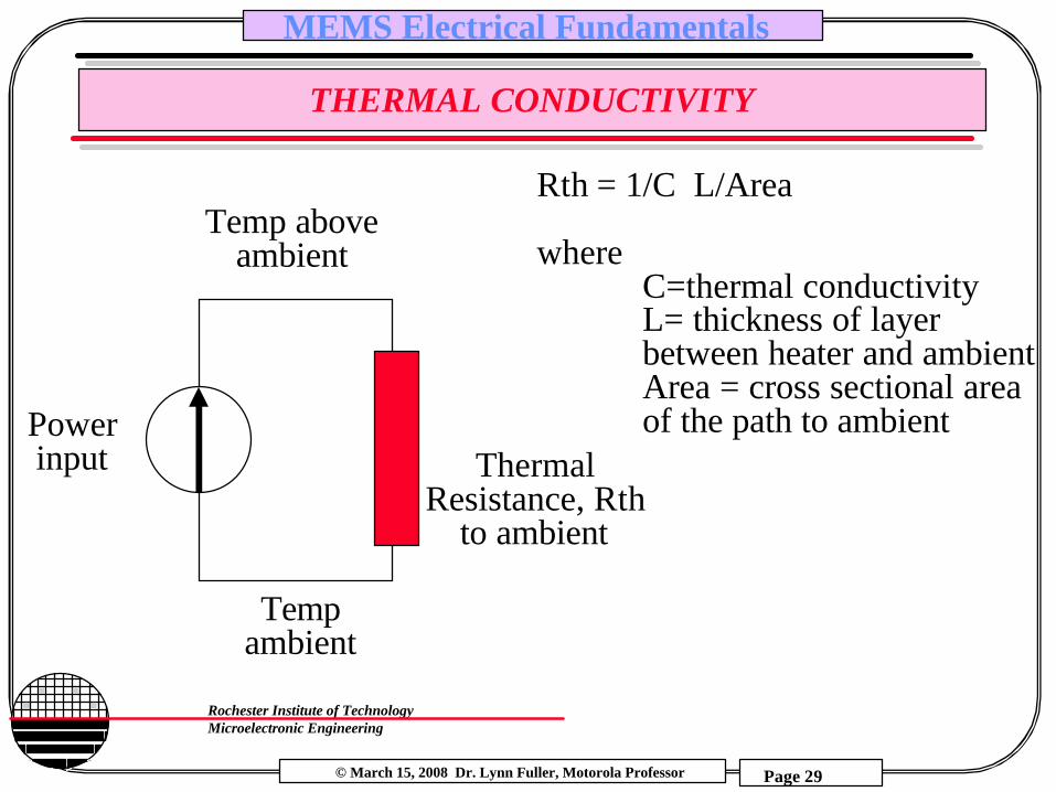
THERMAL CONDUCTIVITY
Tempambient
ThermalResistance, Rth
to ambient
Temp aboveambient
Powerinput
Rth = 1/C L/Area
whereC=thermal conductivityL= thickness of layer between heater and ambientArea = cross sectional areaof the path to ambient

© March 15, 2008 Dr. Lynn Fuller, Motorola Professor
Rochester Institute of TechnologyMicroelectronic Engineering
MEMS Electrical Fundamentals
Page 30
THERMAL PROPERTIES OF SOME MATERIALSMP Coefficient Thermal Specific°C of Thermal Conductivity Heat
Expansionppm/°C w/cmK cal/gm°C
Diamond 1.0 20Single Crystal Silicon 1412 2.33 1.5Poly Silicon 1412 2.33 1.5Silicon Dioxide 1700 0.55 0.014Silicon Nitride 1900 0.8 0.185Aluminum 660 22 2.36 0.215Nickel 1453 13.5 0.90 0.107Chrome 1890 5.1 0.90 0.03Copper 1357 16.1 3.98 0.092Gold 1062 14.2 3.19Tungsten 3370 4.5 1.78Titanium 1660 8.9 0.17Tantalum 2996 6.5 0.54Air 0.00026 0.24Water 0 0.0061 1.00
1 watt = 0.239 cal/sec

© March 15, 2008 Dr. Lynn Fuller, Motorola Professor
Rochester Institute of TechnologyMicroelectronic Engineering
MEMS Electrical Fundamentals
Page 31
HEATER EXAMPLE
Example: Poly heater 100x100µm has sheet resistance of 25 ohms/sq and 9 volts is applied. What temperature will it reach if built on 1 µm thick oxide?
Power = V2/R = 81/25 = 3.24 watt
Rthermal = 1/C L/Area = (1/0.014 watt/cm °C)(1e-4cm/(100e-4cm x100e-4cm))= 71.4 °C/watt
Temperature = Tambient + (3.24) (71.4) = Tambient + 231 °C

© March 15, 2008 Dr. Lynn Fuller, Motorola Professor
Rochester Institute of TechnologyMicroelectronic Engineering
MEMS Electrical Fundamentals
Page 32
TEMPERATURE SENSOR EXAMPLE
Example: A diffused heater is used to heat a sample. The temperature is measured with a poly silicon resistor. For the dimensions given what will the resistance be at 90°C and 65°C
R(T,N) = 1
q µn (T,N) nL
Wt
10µm
50µm
t=1µmNd=n=1E18cm-3
q µn (T=365,N=1e18) n = 1.6e-19 (163) 1e18 = 26.1
q µn (T=390,N=1e18) n = 1.6e-19 (141) 1e18 = 22.6
50,000
R=2212 ohms
R=1916 ohms
© March 15, 2008 Dr. Lynn Fuller, Motorola Professor
Rochester Institute of TechnologyMicroelectronic Engineering
MEMS Electrical Fundamentals
Page 33
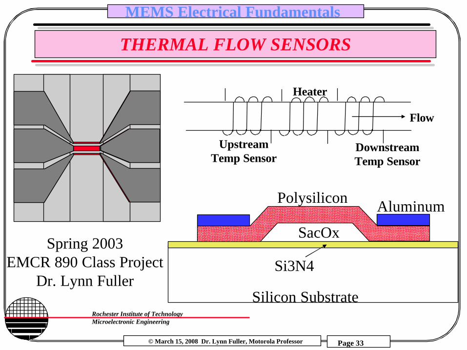
THERMAL FLOW SENSORS
SacOx
Silicon Substrate
Si3N4
Polysilicon Aluminum
Spring 2003EMCR 890 Class Project
Dr. Lynn Fuller
Flow
Downstream Temp Sensor
Heater
Upstream Temp Sensor

© March 15, 2008 Dr. Lynn Fuller, Motorola Professor
Rochester Institute of TechnologyMicroelectronic Engineering
MEMS Electrical Fundamentals
Page 34
GAS FLOW SENSORS
Constant heat (power in watts) input and two temperature measurement devices, one upstream, one downstream. At zero flow both sensors will be at the same temperature. Flow will cause the upstream sensor to be at a lower temperature than the down stream sensor.
Upstream Polysilicon Resistor
Polysilicon heater
Downstream Polysilicon Resistor
GAS

© March 15, 2008 Dr. Lynn Fuller, Motorola Professor
Rochester Institute of TechnologyMicroelectronic Engineering
MEMS Electrical Fundamentals
Page 35
FLOW SENSOR ELECTRONICS
Gnd
+6 Volts
-6 Volts
Vout+-
Constant Power Circuit
Vout near Zero so thatit can be amplified
R1
R2
AD534
10 OHM
AD534_b.pdf

© March 15, 2008 Dr. Lynn Fuller, Motorola Professor
Rochester Institute of TechnologyMicroelectronic Engineering
MEMS Electrical Fundamentals
Page 36
SINGLE WIRE ANEMOMETER
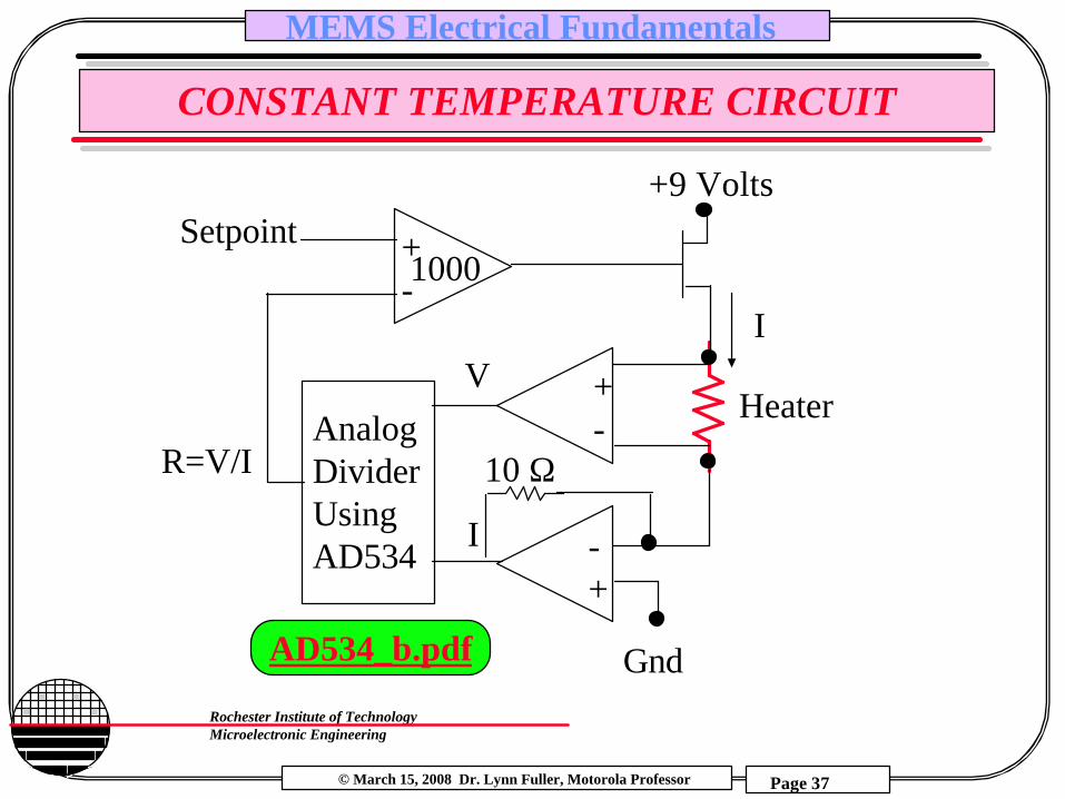
A single heater/sensor element is placed in the flow. The amount of power supplied to keep the temperature constant is proportional to flow. At zero flow a given amount of power Po will heat the resistor to temperature To. With non zero flow more power Pf is needed to keep the resistor at To.
Flow
Heater/Sensor
© March 15, 2008 Dr. Lynn Fuller, Motorola Professor
Rochester Institute of TechnologyMicroelectronic Engineering
MEMS Electrical Fundamentals
Page 37
CONSTANT TEMPERATURE CIRCUIT
AnalogDividerUsingAD534
Gnd
+9 Volts
I
Setpoint
+-
Heater
10 Ω
-+
+-
R=V/I
I
V
1000
AD534_b.pdf
© March 15, 2008 Dr. Lynn Fuller, Motorola Professor
Rochester Institute of TechnologyMicroelectronic Engineering
MEMS Electrical Fundamentals
Page 38
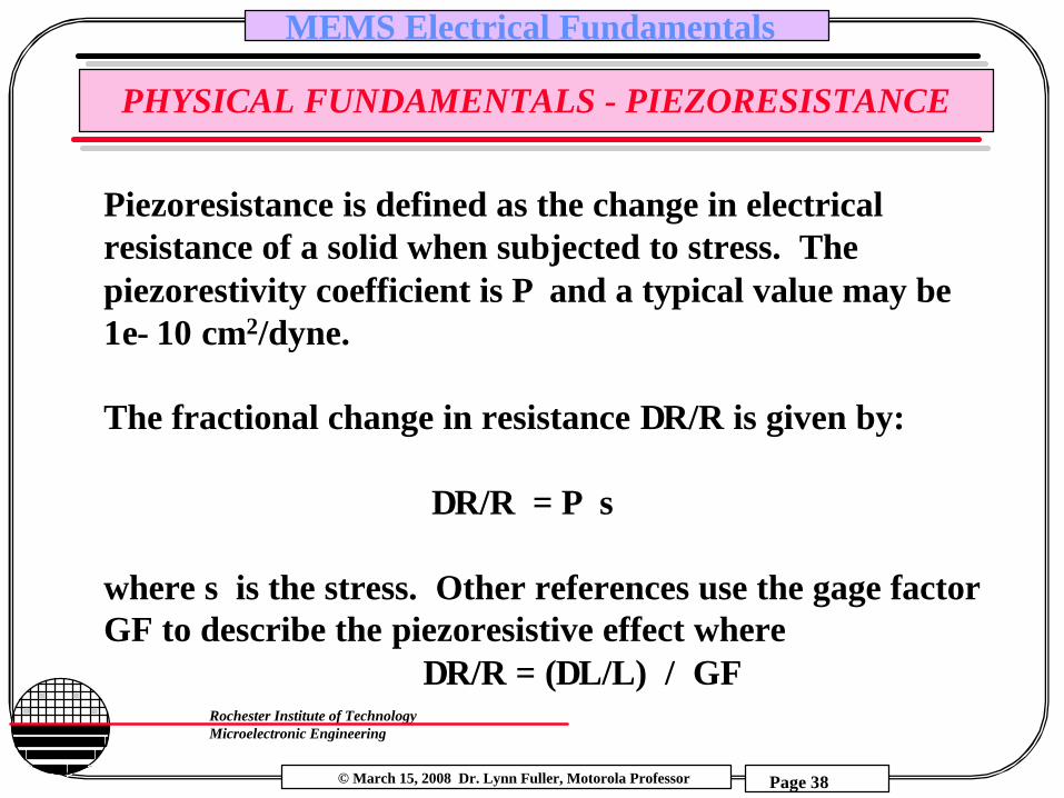
PHYSICAL FUNDAMENTALS - PIEZORESISTANCE
Piezoresistance is defined as the change in electrical resistance of a solid when subjected to stress. The piezorestivity coefficient is Π and a typical value may be 1e−10 cm2/dyne.
The fractional change in resistance ∆R/R is given by:
∆R/R = Π σ
where σ is the stress. Other references use the gage factor GF to describe the piezoresistive effect where
∆R/R = (∆L/L) / GF

© March 15, 2008 Dr. Lynn Fuller, Motorola Professor
Rochester Institute of TechnologyMicroelectronic Engineering
MEMS Electrical Fundamentals
Page 39
EXAMPLE: PIEZORESISTANCE
Example: Find the maximum stress in a simple polysilicon cantilever with the following parameters. Ymax = 1 µm, b=4 µm, h=2µm, L=100 µm
σx=0 = 5.6e7 newton/m2 = 5.6e8 dyne/cm2
From example in mem_mech.ppt
Continue Example: What is the change in resistance given Π = 1e-10 cm2/dyne
∆ R/R = Π σ = (1e-10 cm2/dyne)/(5.6e8 dyne/cm2)= 5.8%
© March 15, 2008 Dr. Lynn Fuller, Motorola Professor
Rochester Institute of TechnologyMicroelectronic Engineering
MEMS Electrical Fundamentals
Page 40
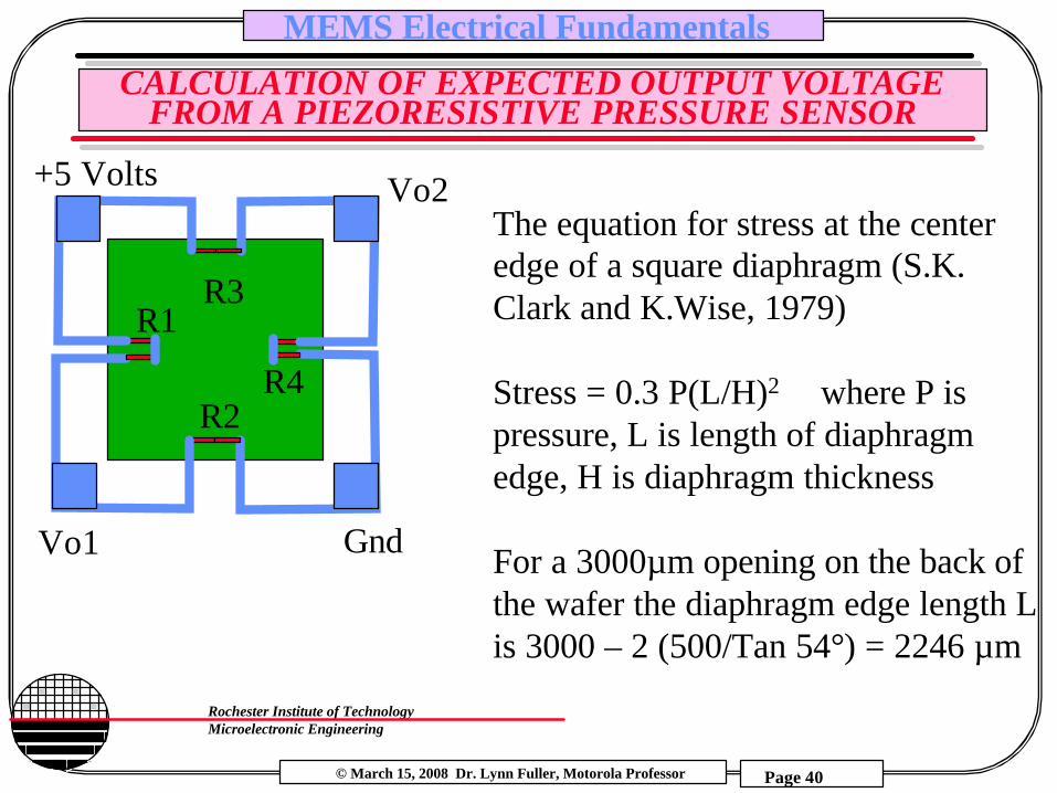
CALCULATION OF EXPECTED OUTPUT VOLTAGE FROM A PIEZORESISTIVE PRESSURE SENSOR
R1R3
R2R4
Gnd
+5 Volts Vo2
Vo1
The equation for stress at the center edge of a square diaphragm (S.K. Clark and K.Wise, 1979)
Stress = 0.3 P(L/H)2 where P is pressure, L is length of diaphragm edge, H is diaphragm thickness
For a 3000µm opening on the back of the wafer the diaphragm edge length L is 3000 – 2 (500/Tan 54°) = 2246 µm

© March 15, 2008 Dr. Lynn Fuller, Motorola Professor
Rochester Institute of TechnologyMicroelectronic Engineering
MEMS Electrical Fundamentals
Page 41
CALCULATION OF EXPECTED OUTPUT VOLTAGE
Stress = 0.3 P (L/H)2
If we apply vacuum to the back of the wafer that is equivalent to and applied pressure of 14.7 psi or 103 N/m2
P = 103 N/m2
L= 2246 µmH= 25 µm
Stress = 2.49E8 N/m2
Hooke’s Law: Stress = E Strain where E is Young’s Modulusσ = E ε
Young’s Modulus ofr silicon is 1.9E11 N/m2
Thus the strain = 1.31E-3 or .131%
© March 15, 2008 Dr. Lynn Fuller, Motorola Professor
Rochester Institute of TechnologyMicroelectronic Engineering
MEMS Electrical Fundamentals
Page 42
CALCULATION OF EXPECTED OUTPUT VOLTAGE
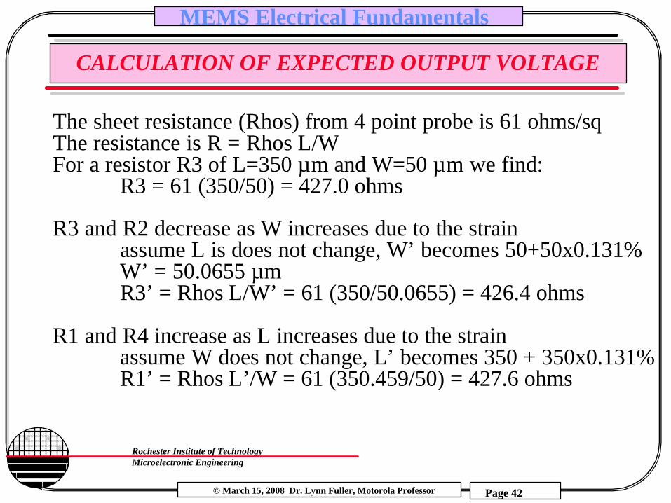
The sheet resistance (Rhos) from 4 point probe is 61 ohms/sqThe resistance is R = Rhos L/WFor a resistor R3 of L=350 µm and W=50 µm we find:
R3 = 61 (350/50) = 427.0 ohms
R3 and R2 decrease as W increases due to the strainassume L is does not change, W’ becomes 50+50x0.131%W’ = 50.0655 µmR3’ = Rhos L/W’ = 61 (350/50.0655) = 426.4 ohms
R1 and R4 increase as L increases due to the strainassume W does not change, L’ becomes 350 + 350x0.131%R1’ = Rhos L’/W = 61 (350.459/50) = 427.6 ohms
© March 15, 2008 Dr. Lynn Fuller, Motorola Professor
Rochester Institute of TechnologyMicroelectronic Engineering
MEMS Electrical Fundamentals
Page 43
CALCULATION OF EXPECTED OUTPUT VOLTAGE
Gnd
5 Volts
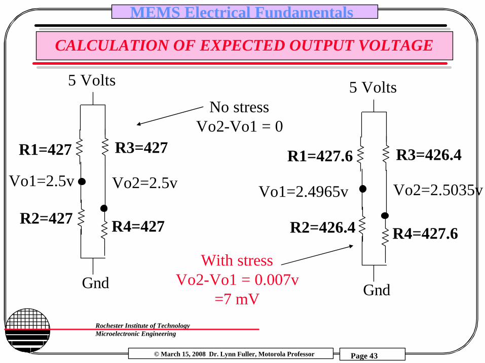
R1=427 R3=427
R2=427 R4=427
Vo2=2.5vVo1=2.5v
Gnd
5 Volts
R1=427.6 R3=426.4
R2=426.4 R4=427.6
Vo2=2.5035vVo1=2.4965v
No stressVo2-Vo1 = 0
With stressVo2-Vo1 = 0.007v
=7 mV
© March 15, 2008 Dr. Lynn Fuller, Motorola Professor
Rochester Institute of TechnologyMicroelectronic Engineering
MEMS Electrical Fundamentals
Page 44
CAPACITORS
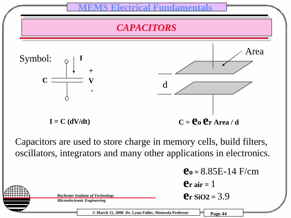
I = C (dV/dt)
I
C V+
-
C = εo εr Area / d
Capacitors are used to store charge in memory cells, build filters, oscillators, integrators and many other applications in electronics.
Symbol:
d
Area
εo = 8.85E-14 F/cmεr air = 1εr SiO2 = 3.9

© March 15, 2008 Dr. Lynn Fuller, Motorola Professor
Rochester Institute of TechnologyMicroelectronic Engineering
MEMS Electrical Fundamentals
Page 45
CAPACITOR SENSOR
C = εo εr Area / d
d
Move one plate relative to the other results in a change
in capacitance
Pressure
Aluminum diaphragm pressure sensor

© March 15, 2008 Dr. Lynn Fuller, Motorola Professor
Rochester Institute of TechnologyMicroelectronic Engineering
MEMS Electrical Fundamentals
Page 46
CAPACITIVE ELECTROSTATIC FORCE
F
++++++++
- - - - - - -
The energy stored in a capacitorcan be equated to the force timesdistance between the plates
W = Fd or F = W/d
2d2εo ε r AV2
F =
d
area A
Energy stored in a parallel plate capacitor Wwith area A and space between plates of d
W = QV = CV2
since Q = CV
dε oε rAC =
ε o = permitivitty of free space = 8.85e-12 Farads/mε r = relative permitivitty (for air ε r = 1)
© March 15, 2008 Dr. Lynn Fuller, Motorola Professor
Rochester Institute of TechnologyMicroelectronic Engineering
MEMS Electrical Fundamentals
Page 47
ELECTROSTATIC FORCE EXAMPLE
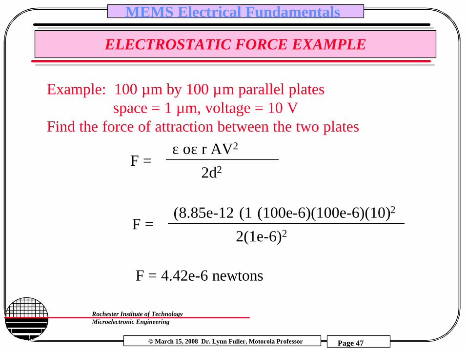
Example: 100 µm by 100 µm parallel platesspace = 1 µm, voltage = 10 V
Find the force of attraction between the two platesε oε r AV2
F =2d2
(8.85e-12)(1)(100e-6)(100e-6)(10)2
F =2(1e-6)2
F = 4.42e-6 newtons

© March 15, 2008 Dr. Lynn Fuller, Motorola Professor
Rochester Institute of TechnologyMicroelectronic Engineering
MEMS Electrical Fundamentals
Page 48
MEMS CANTILEVER WITH ELECTROSTATIC ACTUATOR
Poly 2
Poly 1
Metal
y
V0 10 20 30
1
2
3um
3µm gap
As the voltage is increased the electrostatic force starts to pull down the cantilever. The spring constant opposes the force but at the same time the gap is increased and the force increases. The electrostatic force increases with 1/d2 so eventually a point is reached where it is larger than the spring and the cantilever snaps down all the way. The voltage has to be reduced almost to zero to release the cantilever.
© March 15, 2008 Dr. Lynn Fuller, Motorola Professor
Rochester Institute of TechnologyMicroelectronic Engineering
MEMS Electrical Fundamentals
Page 49
MEMS CANTILEVER WITH ELECTROSTATIC ACTUATOR
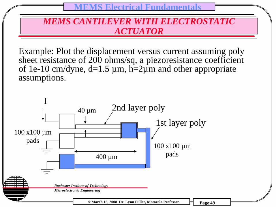
Example: Plot the displacement versus current assuming poly sheet resistance of 200 ohms/sq, a piezoresistance coefficient of 1e-10 cm/dyne, d=1.5 µm, h=2µm and other appropriate assumptions.
1st layer poly
2nd layer polyI
100 x100 µmpads
400 µm
40 µm
100 x100 µmpads

© March 15, 2008 Dr. Lynn Fuller, Motorola Professor
Rochester Institute of TechnologyMicroelectronic Engineering
MEMS Electrical Fundamentals
Page 50
SOLUTION FOR y VERSUS I
y
I
I
V
V = I(R+πσ)
R=2000 Ω
R=2000 Ω
ε oε r AV2
F =2d2
Ymax 3 E bh3
F =12L3
12 F Lσx=0 =
2b h2
Ymax 3 E bh3
F =12L3
© March 15, 2008 Dr. Lynn Fuller, Motorola Professor
Rochester Institute of TechnologyMicroelectronic Engineering
MEMS Electrical Fundamentals
Page 51
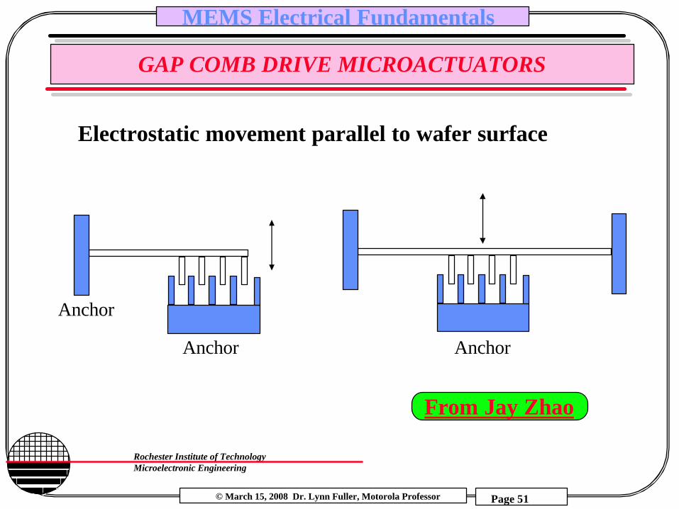
GAP COMB DRIVE MICROACTUATORS
Electrostatic movement parallel to wafer surface
AnchorAnchor
Anchor
From Jay Zhao

© March 15, 2008 Dr. Lynn Fuller, Motorola Professor
Rochester Institute of TechnologyMicroelectronic Engineering
MEMS Electrical Fundamentals
Page 52
CALCULATION OF DISPLACEMENT VS VOLTAGE
t
L
d
movement
C = εr εo t L/d
F = εr εo t V2 / 2 d

© March 15, 2008 Dr. Lynn Fuller, Motorola Professor
Rochester Institute of TechnologyMicroelectronic Engineering
MEMS Electrical Fundamentals
Page 53
COMBINED SPRING ELECTROSTATIC DRIVE AND CAPACITIVE OR PIEZORESISTIVE READ OUT
R
Anchor
C1
C2
C1
© March 15, 2008 Dr. Lynn Fuller, Motorola Professor
Rochester Institute of TechnologyMicroelectronic Engineering
MEMS Electrical Fundamentals
Page 54
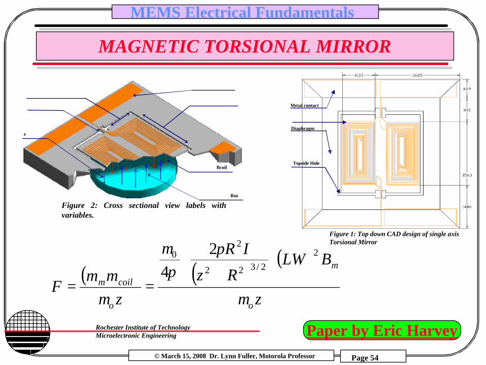
MAGNETIC TORSIONAL MIRROR
W
Contact
L
Supporting arm
z
Bcoil
Bm
Figure 2: Cross sectional view labels with variables.
( ) ( )( )
Nz
BLWRz
IR
zmm
Fo
m
o
coilm
µ
ππ
µ
µ
22/322
20 2
4
+==
Metal contact
Topside Hole
Diaphragm
Figure 1: Top down CAD design of single axis Torsional Mirror
Paper by Eric Harvey
© March 15, 2008 Dr. Lynn Fuller, Motorola Professor
Rochester Institute of TechnologyMicroelectronic Engineering
MEMS Electrical Fundamentals
Page 55
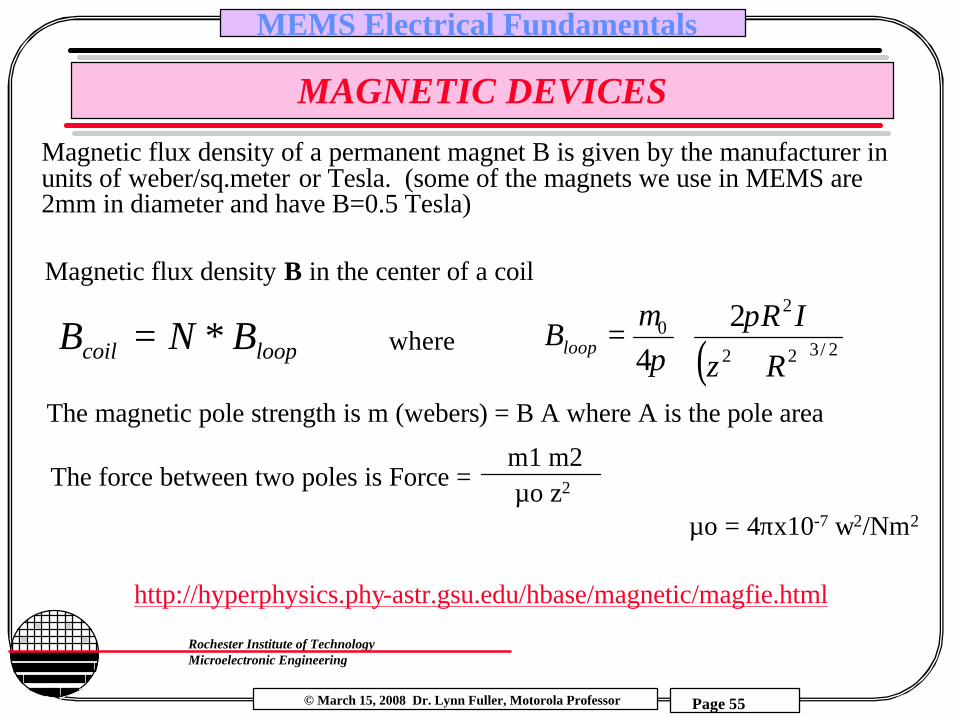
MAGNETIC DEVICES
http://hyperphysics.phy-astr.gsu.edu/hbase/magnetic/magfie.html
Magnetic flux density B in the center of a coil
( )
+= 2/322
20 2
4 Rz
IRBloopπ
πµ
loopcoil BNB *= where
The magnetic pole strength is m (webers) = B A where A is the pole area
Magnetic flux density of a permanent magnet B is given by the manufacturer in units of weber/sq.meter or Tesla. (some of the magnets we use in MEMS are 2mm in diameter and have B=0.5 Tesla)
The force between two poles is Force = µo z2
m1 m2
µo = 4πx10-7 w2/Nm2

© March 15, 2008 Dr. Lynn Fuller, Motorola Professor
Rochester Institute of TechnologyMicroelectronic Engineering
MEMS Electrical Fundamentals
Page 56
MAGNETIC DEVICES
Force on a straight conductor in a uniform magnetic field.
F = I L X B
( ) ( )( )
Nz
BLWRz
IR
zmm
Fo
m
o
coilm
µ
ππ
µ
µ
22/322
20 2
4
+==
Force on a coil with current I in a uniform magnetic field
© March 15, 2008 Dr. Lynn Fuller, Motorola Professor
Rochester Institute of TechnologyMicroelectronic Engineering
MEMS Electrical Fundamentals
Page 57
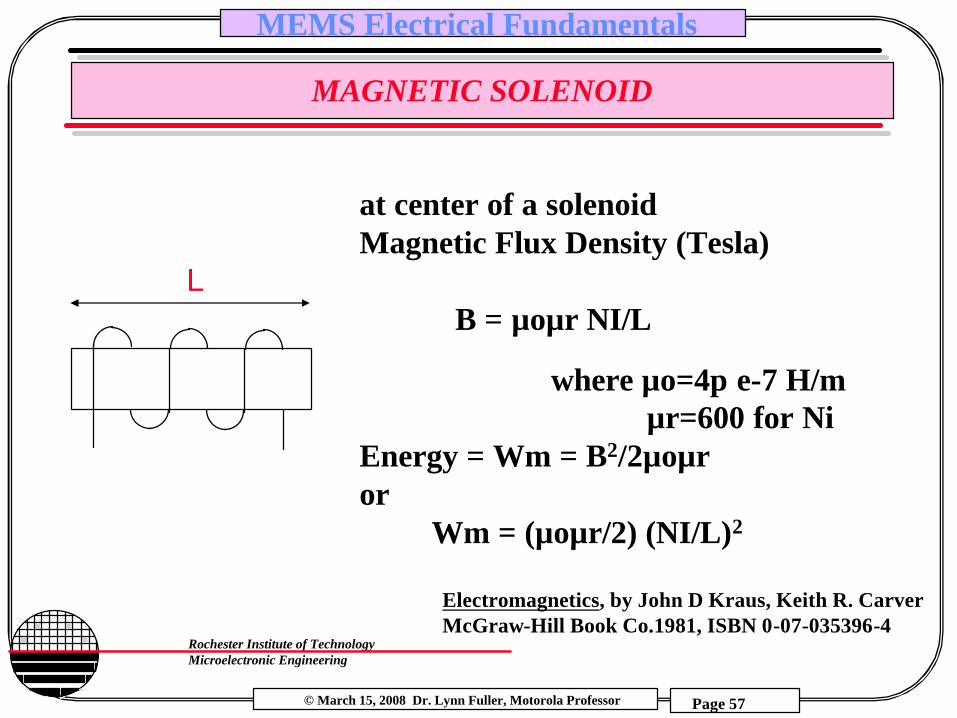
MAGNETIC SOLENOID
Electromagnetics, by John D Kraus, Keith R. CarverMcGraw-Hill Book Co.1981, ISBN 0-07-035396-4
at center of a solenoidMagnetic Flux Density (Tesla)
B = µoµr NI/L
where µo=4π e-7 H/mµr=600 for Ni
Energy = Wm = B2/2µoµror
Wm = (µoµr/2) (NI/L)2
L
© March 15, 2008 Dr. Lynn Fuller, Motorola Professor
Rochester Institute of TechnologyMicroelectronic Engineering
MEMS Electrical Fundamentals
Page 58
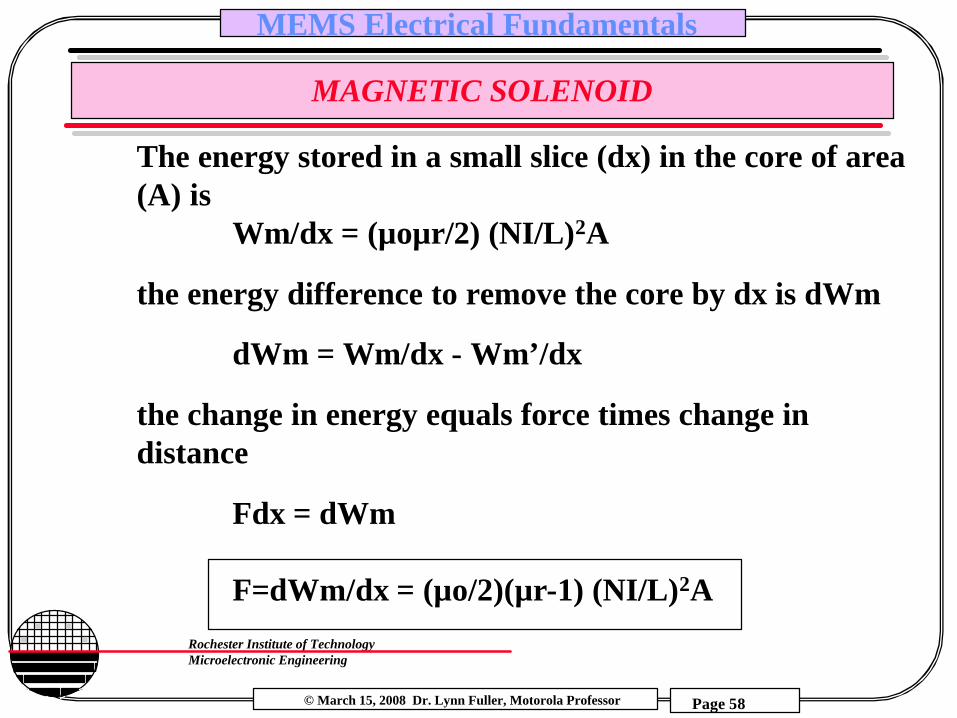
MAGNETIC SOLENOID
The energy stored in a small slice (dx) in the core of area (A) is
Wm/dx = (µoµr/2) (NI/L)2A
the energy difference to remove the core by dx is dWm
dWm = Wm/dx - Wm’/dx
the change in energy equals force times change in distance
Fdx = dWm
F=dWm/dx = (µo/2)(µr-1) (NI/L)2A

© March 15, 2008 Dr. Lynn Fuller, Motorola Professor
Rochester Institute of TechnologyMicroelectronic Engineering
MEMS Electrical Fundamentals
Page 59
MAGNETIC SOLENOID
Example: Given a nickel core solenoid of length 200 µm with 25 turns and 0.1 amp of current. The cross-sectional area is 40 µm by 2µm. Calculate the force needed to move the core.
F = (µo/2)(µr-1) (NI/L)2A
F = (4π e-7/2)(600-1)[(25)(0.1)/200e-6)]2(40e-6)(2e-6)
= 4.7e-6 Newton
© March 15, 2008 Dr. Lynn Fuller, Motorola Professor
Rochester Institute of TechnologyMicroelectronic Engineering
MEMS Electrical Fundamentals
Page 60
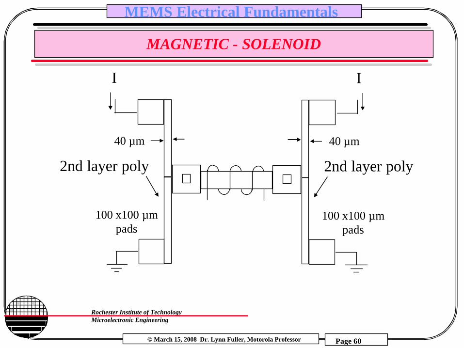
MAGNETIC - SOLENOID
2nd layer poly
I
100 x100 µmpads
40 µm
2nd layer poly
I
100 x100 µmpads
40 µm

© March 15, 2008 Dr. Lynn Fuller, Motorola Professor
Rochester Institute of TechnologyMicroelectronic Engineering
MEMS Electrical Fundamentals
Page 61
EXAMPLE - SOLENOID

© March 15, 2008 Dr. Lynn Fuller, Motorola Professor
Rochester Institute of TechnologyMicroelectronic Engineering
MEMS Electrical Fundamentals
Page 62
MAGNETIC FIELD SENSORS
Lateral MagnetotransistorMOS Magnetotransistor
F=q(v x B)
See UGIM 1999Add Picture

© March 15, 2008 Dr. Lynn Fuller, Motorola Professor
Rochester Institute of TechnologyMicroelectronic Engineering
MEMS Electrical Fundamentals
Page 63
PIEZOELECTRIC DRIVES
A piezoelectric material will exhibit a change in length in response to an applied voltage. The reverse is also possible where an applied force causes the generation of a voltage. Single crystal quartz has been used for piezeoelectric devices such as gas grill igniters and piezoelectric linear motors. Thin films of various materials (organic and inorganic) exhibit piezoelectric properties. ZnO films 0.2 µm thick are sputtered and annealed 25 min, 950C giving piezoelectric properties. Many piezoelectric materials also exhibit pyroelectricproperties (voltage - heat).
more
© March 15, 2008 Dr. Lynn Fuller, Motorola Professor
Rochester Institute of TechnologyMicroelectronic Engineering
MEMS Electrical Fundamentals
Page 64
SEEBECK EFFECT
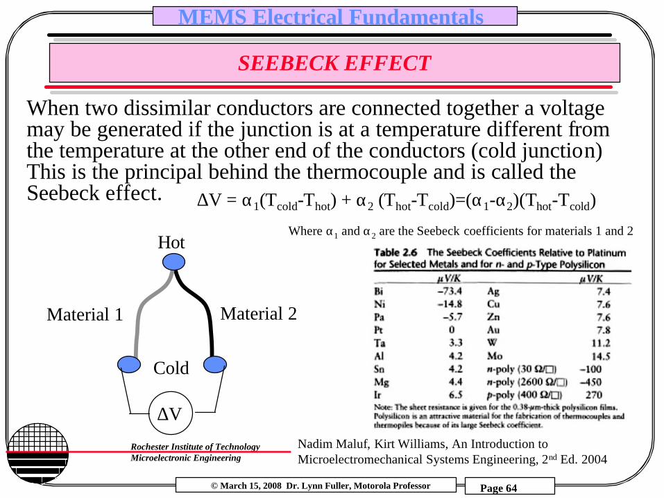
When two dissimilar conductors are connected together a voltage may be generated if the junction is at a temperature different from the temperature at the other end of the conductors (cold junction) This is the principal behind the thermocouple and is called the Seebeck effect.
∆V
Material 2Material 1
Hot
Cold
Nadim Maluf, Kirt Williams, An Introduction to Microelectromechanical Systems Engineering, 2nd Ed. 2004
∆V = α1(Tcold-Thot) + α2 (Thot-Tcold)=(α1-α2)(Thot-Tcold)
Where α1 and α2 are the Seebeck coefficients for materials 1 and 2

© March 15, 2008 Dr. Lynn Fuller, Motorola Professor
Rochester Institute of TechnologyMicroelectronic Engineering
MEMS Electrical Fundamentals
Page 65
PELTIER EFFECT
Heat pump device that works on the gain in electron energy for materials with low work function and the loss in energy for materials with higher work function. Electrons are at higher energy (lower work function) in n-type silicon.
I
heat
heat
n nn pp
Cu
electronsCu
Cu
CuCu Cu
Cu

© March 15, 2008 Dr. Lynn Fuller, Motorola Professor
Rochester Institute of TechnologyMicroelectronic Engineering
MEMS Electrical Fundamentals
Page 66
PELTIER HEAT PUMP
Ferrotec America Corp1050 Perimeter Rd, #202Manchester, NH 03103(603) 626-0700
© March 15, 2008 Dr. Lynn Fuller, Motorola Professor
Rochester Institute of TechnologyMicroelectronic Engineering
MEMS Electrical Fundamentals
Page 67
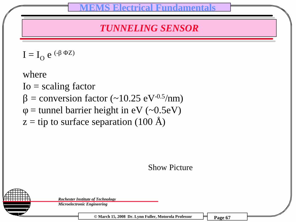
TUNNELING SENSOR
I = IO e (-β ΦZ)
where Io = scaling factorβ = conversion factor (~10.25 eV-0.5/nm)φ = tunnel barrier height in eV (~0.5eV)z = tip to surface separation (100 Å)
Show Picture
© March 15, 2008 Dr. Lynn Fuller, Motorola Professor
Rochester Institute of TechnologyMicroelectronic Engineering
MEMS Electrical Fundamentals
Page 68
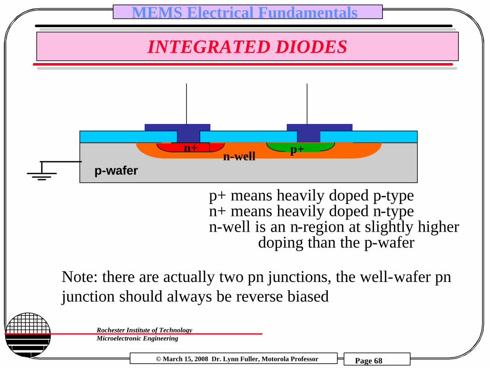
INTEGRATED DIODES
p-wafer
n+ p+n-well
p+ means heavily doped p-typen+ means heavily doped n-typen-well is an n-region at slightly higher
doping than the p-wafer
Note: there are actually two pn junctions, the well-wafer pnjunction should always be reverse biased

© March 15, 2008 Dr. Lynn Fuller, Motorola Professor
Rochester Institute of TechnologyMicroelectronic Engineering
MEMS Electrical Fundamentals
Page 69
DIODE TEMPERATURE DEPENDENCE
Id = IS [EXP (q VD/KT) -1]Neglect the –1 in forward bias, Solve for VD
VD = (KT/q) ln (Id/IS) = (KT/q) (ln(Id) – ln(Is))
Take dVD/dT: note Id is not a function of T but Is is
dVD/dT = (KT/q) (dln(Id)/dT – dln(Is)/dT) + K/q (ln(Id) – ln(Is))zero VD/T from eq 1
RewrittendVD/dT = VD/T - (KT/q) ((1/Is) dIs/dT )
Now evaluate the second term, recall
Is = qA (Dp/(LpNd) +Dn/(LnNa))ni2
eq 1
eq 2
Note: Dn and Dp are proportional to 1/T
© March 15, 2008 Dr. Lynn Fuller, Motorola Professor
Rochester Institute of TechnologyMicroelectronic Engineering
MEMS Electrical Fundamentals
Page 70
DIODE TEMPERATURE DEPENDENCE
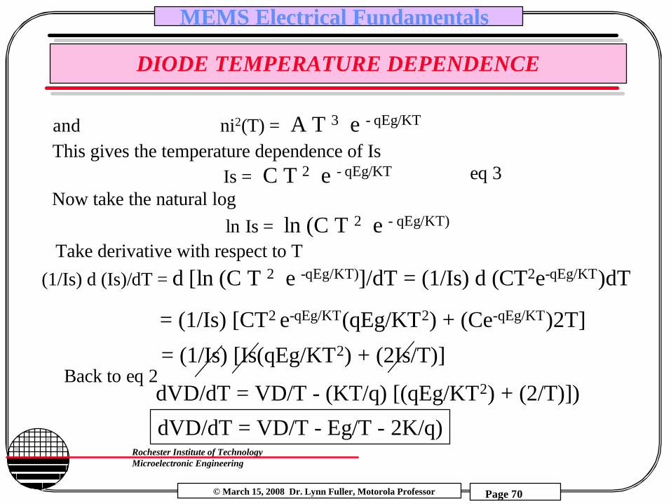
and ni2(T) = A T 3 e - qEg/KT
This gives the temperature dependence of IsIs = C T 2 e - qEg/KT
Now take the natural logln Is = ln (C T 2 e - qEg/KT)
Take derivative with respect to T(1/Is) d (Is)/dT = d [ln (C T 2 e -qEg/KT)]/dT = (1/Is) d (CT2e-qEg/KT)dT
eq 3
= (1/Is) [CT2 e-qEg/KT(qEg/KT2) + (Ce-qEg/KT)2T]
= (1/Is) [Is(qEg/KT2) + (2Is/T)]Back to eq 2
dVD/dT = VD/T - (KT/q) [(qEg/KT2) + (2/T)])
dVD/dT = VD/T - Eg/T - 2K/q)
© March 15, 2008 Dr. Lynn Fuller, Motorola Professor
Rochester Institute of TechnologyMicroelectronic Engineering
MEMS Electrical Fundamentals
Page 71
EXAMPLE: DIODE TEMPERATURE DEPENDENCE
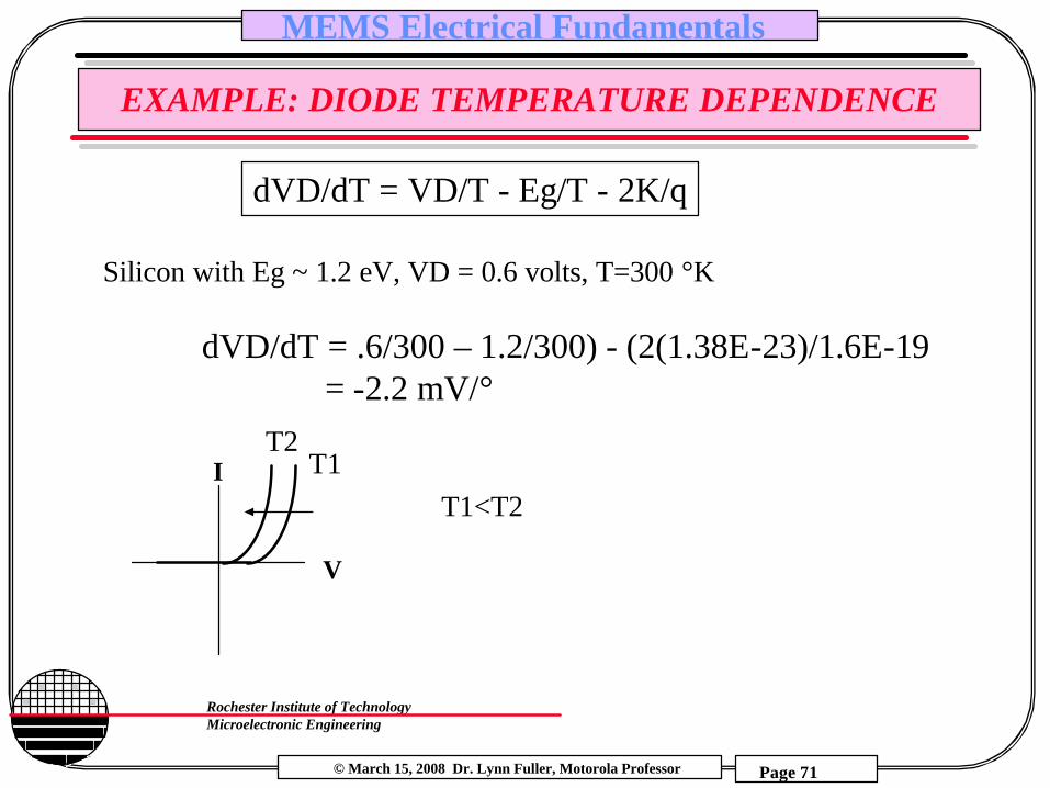
dVD/dT = VD/T - Eg/T - 2K/q
Silicon with Eg ~ 1.2 eV, VD = 0.6 volts, T=300 °K
dVD/dT = .6/300 – 1.2/300) - (2(1.38E-23)/1.6E-19= -2.2 mV/°
I
V
T1T2
T1<T2

© March 15, 2008 Dr. Lynn Fuller, Motorola Professor
Rochester Institute of TechnologyMicroelectronic Engineering
MEMS Electrical Fundamentals
Page 72
PHYSICAL FUNDAMENTALS - PHOTOELECTRIC
B -
P+ Ionized Immobile Phosphrous donor atomIonized Immobile Boron acceptor atom
Phosphrous donor atom and electronP+-
B-+ Boron acceptor atom and hole
n-type
p-typeB - P+
B -B -
B -B -
P+ P+P+P+
P+
P+
P+-
B-+
εB -B -
P+-
P+-
P+-
B-+
-+
-+
I
electronand hole
pair
-+
-+
space charge layer

© March 15, 2008 Dr. Lynn Fuller, Motorola Professor
Rochester Institute of TechnologyMicroelectronic Engineering
MEMS Electrical Fundamentals
Page 73
PHOTODIODE
I
V
n
p
IV
I+V-
More Light No Light
Most Light

© March 15, 2008 Dr. Lynn Fuller, Motorola Professor
Rochester Institute of TechnologyMicroelectronic Engineering
MEMS Electrical Fundamentals
Page 74
CHARGE COLLECTION IN MOS STRUCTURES
ε
-+
-+
electronand hole
pair
-+
-+
depletion region
-+
-- -
p-type
+ V
B -
B -
B -
B -
λ1 λ3 λ4λ2
thin poly gate
E = hν = hc / λ
h = 6.625 e-34 j/s = (6.625 e-34/1.6e-19) eV/s
E = 1.55 eV (red)E = 2.50 eV (green)E = 4.14 eV (blue)
© March 15, 2008 Dr. Lynn Fuller, Motorola Professor
Rochester Institute of TechnologyMicroelectronic Engineering
MEMS Electrical Fundamentals
Page 75
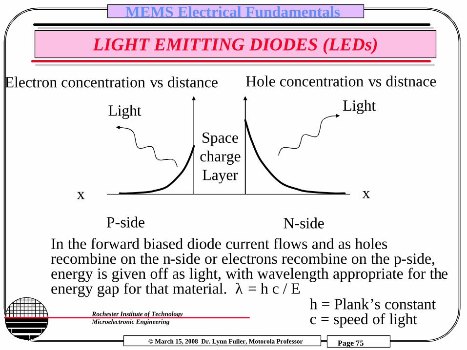
LIGHT EMITTING DIODES (LEDs)
P-side N-side
SpacechargeLayer
LightLight
Hole concentration vs distnace
xx
Electron concentration vs distance
In the forward biased diode current flows and as holes recombine on the n-side or electrons recombine on the p-side, energy is given off as light, with wavelength appropriate for the energy gap for that material. λ = h c / E
h = Plank’s constantc = speed of light
© March 15, 2008 Dr. Lynn Fuller, Motorola Professor
Rochester Institute of TechnologyMicroelectronic Engineering
MEMS Electrical Fundamentals
Page 76
REFERENCES
1. Mechanics of Materials, by Ferdinand P. Beer, E. Russell Johnston, Jr., McGraw-Hill Book Co.1981, ISBN 0-07-004284-5
2. Electromagnetics, by John D Kraus, Keith R. Carver, McGraw-Hill Book Co.1981, ISBN 0-07-035396-4
3. “Etch Rates for Micromachining Processing”, Journal of Microelectromechanical Systems, Vol.5, No.4, December 1996.
4. “Design, Fabrication, and Operation of Submicron Gap Comb-Drive Microactuators”, Hirano, et.al. , Journal of Microelectromechanical Systems, Vol.1, No.1, March 1992, p52.
5. “Piezoelectric Cantilever Microphone and Microspeaker”, Lee, Ried, White, Journal of Microelectromechanical Systems, Vol.5, No.4, December 1996.
6. “Crystalline Semiconductor Micromachine”, Seidel, Proceedings of the 4th Int. Conf. on Solid State Sensors and Actuators 1987, p 104
7. Fundamentals of Microfabrication, M. Madou, CRC Press, New York, 19978. Element properties: http://web.mit.edu/3.091/www/pt/

© March 15, 2008 Dr. Lynn Fuller, Motorola Professor
Rochester Institute of TechnologyMicroelectronic Engineering
MEMS Electrical Fundamentals
Page 77
HOMEWORK – MEMS ELECTRICAL
1. Calculate the voltage needed to pull down a polysilicon cantiliverby electrostatic force. Make appropriate assumptions for dimensions.
2. Calculate the number of fingers needed in an electrostatic comb drive to create a force of 10 micro newtons. Make appropriate assumptions for dimensions.
3. What coil current is needed to create a force of 10 micro newtonsin a magnetic field of 0.5 Tesla. Make appropriate assumptions for dimensions.
4. In a thermocouple made of aluminum on n+ poly what voltage will be generated for a temperature difference of 70 °C?
5. A diode is used as a temperature sensor and is forward biased with a 1.5 Volt battery in series with a 10Kohm resistor. If the device is used to measure body temperature (nominal 98.6 °F) how much change in voltage across the diode if someone had a temperature of 102.6°F.
Related Documents