© January 3, 2017 Dr. Lynn Fuller, Professor Rochester Institute of Technology Microelectronic Engineering MEMs Applications – Microphones Page 1 ROCHESTER INSTITUTE OF TEHNOLOGY MICROELECTRONIC ENGINEERING 1-3-2017 mem_app_mic.ppt Microelectromechanical Systems (MEMs) Applications – Microphones Dr. Lynn Fuller Webpage: http://people.rit.edu/lffeee Microelectronic Engineering Rochester Institute of Technology 82 Lomb Memorial Drive Rochester, NY 14623-5604 Email: [email protected] Program webpage: http ://www.rit.edu/kgcoe/microelectronic/

Welcome message from author
This document is posted to help you gain knowledge. Please leave a comment to let me know what you think about it! Share it to your friends and learn new things together.
Transcript

© January 3, 2017 Dr. Lynn Fuller, Professor
Rochester Institute of Technology
Microelectronic Engineering
MEMs Applications – Microphones
Page 1
ROCHESTER INSTITUTE OF TEHNOLOGYMICROELECTRONIC ENGINEERING
1-3-2017 mem_app_mic.ppt
Microelectromechanical Systems (MEMs)Applications – Microphones
Dr. Lynn Fuller
Webpage: http://people.rit.edu/lffeeeMicroelectronic Engineering
Rochester Institute of Technology82 Lomb Memorial Drive
Rochester, NY 14623-5604Email: [email protected]
Program webpage: http://www.rit.edu/kgcoe/microelectronic/
© January 3, 2017 Dr. Lynn Fuller, Professor
Rochester Institute of Technology
Microelectronic Engineering
MEMs Applications – Microphones
Page 2
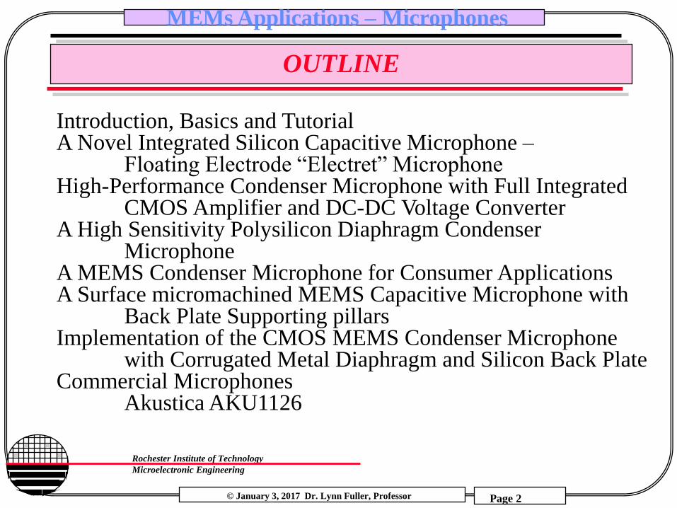
OUTLINE
Introduction, Basics and TutorialA Novel Integrated Silicon Capacitive Microphone –
Floating Electrode “Electret” MicrophoneHigh-Performance Condenser Microphone with Full Integrated
CMOS Amplifier and DC-DC Voltage ConverterA High Sensitivity Polysilicon Diaphragm Condenser
MicrophoneA MEMS Condenser Microphone for Consumer ApplicationsA Surface micromachined MEMS Capacitive Microphone with
Back Plate Supporting pillarsImplementation of the CMOS MEMS Condenser Microphone
with Corrugated Metal Diaphragm and Silicon Back PlateCommercial Microphones
Akustica AKU1126

© January 3, 2017 Dr. Lynn Fuller, Professor
Rochester Institute of Technology
Microelectronic Engineering
MEMs Applications – Microphones
Page 3
INTRODUCTION
Microphone TypesElectret: output is change in voltageCondenser: output is change in capacitancePiezoresistive: change in resistanceOther: accelerometer, optical, piezoelectric, electromagnetic, etc.
Pressures: SPLDB – Sound Pressure Level
Diaphragm Calculations: Approximate diaphragm displacement, DC, Stress, DR
Signal Conditioning: Circuits (Analog or Digital output)
Other: Sensitivity, Frequency Response, etc.
© January 3, 2017 Dr. Lynn Fuller, Professor
Rochester Institute of Technology
Microelectronic Engineering
MEMs Applications – Microphones
Page 4
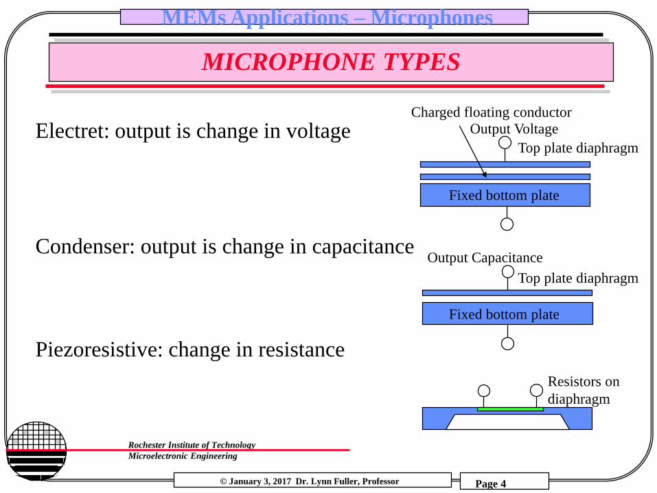
MICROPHONE TYPES
Electret: output is change in voltage
Fixed bottom plate
Top plate diaphragm
Output Capacitance
Charged floating conductor
Top plate diaphragm
Fixed bottom plate
Output Voltage
Condenser: output is change in capacitance
Piezoresistive: change in resistance
Resistors on
diaphragm

© January 3, 2017 Dr. Lynn Fuller, Professor
Rochester Institute of Technology
Microelectronic Engineering
MEMs Applications – Microphones
Page 5
PRESSURE UNITS
Table of Pressure Conversions
1 atm = 14.696 lbs/in2 = 760.00 mmHg
1 atm = 101.32 kPa = 1.013 x 10⁶ dynes/cm2
1Pascal = 1.4504 x 10⁻⁴ lbs/in2 =1 N/m2 = 10 dynes/cm2
1 mmHg = 1 Torr (at 0oC )
1SPL (Sound Pressure Levels) = 0.0002 dynes/cm2
Average speech = 70 dBSPL = 0.645 dynes/cm2
Pain = 130 dBSPL = 645 dyne/cm2
Whisper = 18 dBSPL = 1.62 x 10⁻³ dyne/cm2
Example:
70dBSPL = 0.645 dynes/cm2 = 0.0645 N/m2 = 9.35E-6 lbs/in2

© January 3, 2017 Dr. Lynn Fuller, Professor
Rochester Institute of Technology
Microelectronic Engineering
MEMs Applications – Microphones
Page 6
DIAPHRAGM CALCULATIONS
500um Diaphragm, 1.7um thick, silicon, 2um gap
Gives: Co = 0.87pF and change of Cm = 0.027fF

© January 3, 2017 Dr. Lynn Fuller, Professor
Rochester Institute of Technology
Microelectronic Engineering
MEMs Applications – Microphones
Page 7
DIAPHRAGM CALCULATIONS
1500um Diaphragm, 1.7 um thick, silicon, 2um gap
Gives: Co = 7.8pF and change of Cm = 20fF

© January 3, 2017 Dr. Lynn Fuller, Professor
Rochester Institute of Technology
Microelectronic Engineering
MEMs Applications – Microphones
Page 8
DIAPHRAGM CALCULATIONS
1500um Diaphragm, 1.7um thick, polyimide, 2um gap
Gives: Co = 7.8pF and change of Cm = 1700fF

© January 3, 2017 Dr. Lynn Fuller, Professor
Rochester Institute of Technology
Microelectronic Engineering
MEMs Applications – Microphones
Page 9
DIAPHRAGM CALCULATIONS
500um Diaphragm, 1um thick, polyimide, 1um gap
Gives: Co = 1.7368pF and change of Cm = 23.8fF

© January 3, 2017 Dr. Lynn Fuller, Professor
Rochester Institute of Technology
Microelectronic Engineering
MEMs Applications – Microphones
Page 10
DIAPHRAGM CALCULATIONS
1500um Diaphragm,
Silicon
1.7um thick
2um gap
Co = 7.8pF
Cm = 20fF Change
Resonant Frequency
fo = 13,000 Hz

© January 3, 2017 Dr. Lynn Fuller, Professor
Rochester Institute of Technology
Microelectronic Engineering
MEMs Applications – Microphones
Page 11
DIAPHRAGM CALCULATIONS
1500um Diaphragm,
Polyimide
1.7um thick
2um gap
Co = 7.8pF
Cm = 1.7pF Change
Resonant Frequency
fo = 2,000 Hz

© January 3, 2017 Dr. Lynn Fuller, Professor
Rochester Institute of Technology
Microelectronic Engineering
MEMs Applications – Microphones
Page 12
SUMMARY
1. Need large thin diaphragms that give enough displacement so that the change in capacitance is 100’s of fF.
2. The resonant frequency needs to be considered. Typically it should be greater than 20,000 Hz (depends on application)
3. The fabrication technology: single wafer, CMOS compatible, low temperature, surface MEMS process.
4. Electrical output signal processing …
5. Desired specifications: Sensitivity of few 10’s of mV/dBSPL more is better, free field (not including packaging acoustic effects) frequency response up to 20KHz flat or increasing with frequency,

© January 3, 2017 Dr. Lynn Fuller, Professor
Rochester Institute of Technology
Microelectronic Engineering
MEMs Applications – Microphones
Page 13
ELECTRET MICROPHONE
© January 3, 2017 Dr. Lynn Fuller, Professor
Rochester Institute of Technology
Microelectronic Engineering
MEMs Applications – Microphones
Page 14
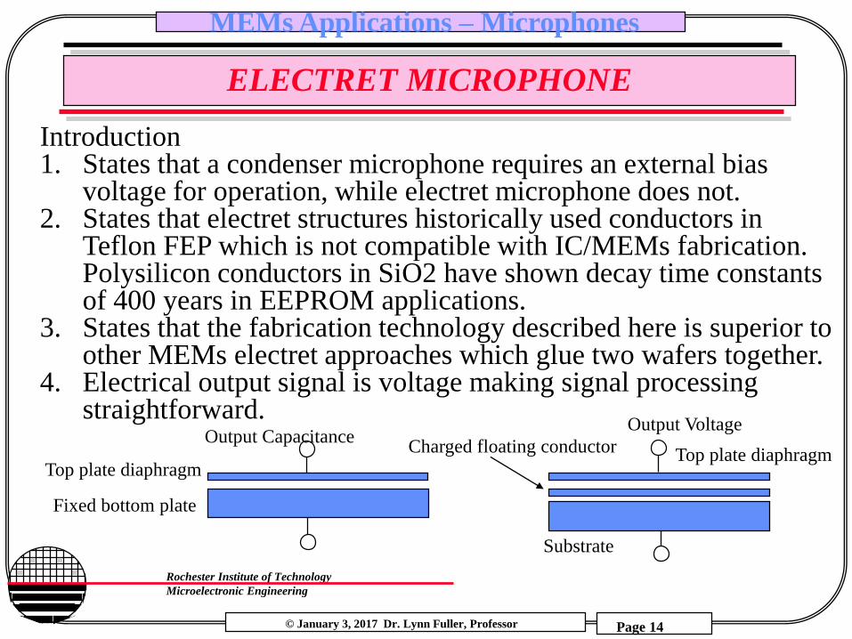
ELECTRET MICROPHONE
Introduction1. States that a condenser microphone requires an external bias
voltage for operation, while electret microphone does not.2. States that electret structures historically used conductors in
Teflon FEP which is not compatible with IC/MEMs fabrication. Polysilicon conductors in SiO2 have shown decay time constants of 400 years in EEPROM applications.
3. States that the fabrication technology described here is superior to other MEMs electret approaches which glue two wafers together.
4. Electrical output signal is voltage making signal processing straightforward.
Fixed bottom plate
Charged floating conductor
Top plate diaphragmTop plate diaphragm
Substrate
Output CapacitanceOutput Voltage

© January 3, 2017 Dr. Lynn Fuller, Professor
Rochester Institute of Technology
Microelectronic Engineering
MEMs Applications – Microphones
Page 15
ELECTRET MICROPHONE

© January 3, 2017 Dr. Lynn Fuller, Professor
Rochester Institute of Technology
Microelectronic Engineering
MEMs Applications – Microphones
Page 16
ELECTRET MICROPHONE

© January 3, 2017 Dr. Lynn Fuller, Professor
Rochester Institute of Technology
Microelectronic Engineering
MEMs Applications – Microphones
Page 17
ELECTRET MICROPHONE
4” wafers, 500 µm, (100), n-type, 2 ohm-cm,Backside polished
Deposit oxide (7000 Å) and nitride (2000 Å)
Etch from back of wafer leaving 40 µm thick silicon layer.
Fabricate JFET’s for amplifier circuit.
Etch V grove corrugation from front of wafer, almost but not through the 40 µm thick silicon layer
Ion implant P+ areas for hot-electron injection charging of floating polysilicon gate
Grow 5000 Å oxide followed by 2000 Å polysilicon for floating electrode, dope poly, and cover with low stress silicon nitride

© January 3, 2017 Dr. Lynn Fuller, Professor
Rochester Institute of Technology
Microelectronic Engineering
MEMs Applications – Microphones
Page 18
ELECTRET MICROPHONE
Next a sacrificial layer of LTO phosphosilicate glass is deposited totaling 2.7 µm in thickness
A poly layer 8000 Å thick is deposited for the diaphragm, and doped by ion implant, followed by a 2000 Å silicon nitride layer, a 1050 C nitrogen anneal is used to reduce stress.
Contact cuts are plasma etched and metal is deposited and patterned.
The back of the wafer is Reactive Ion Etched (RIE) to open up the V grove prior to sacrificial oxide etch in Buffered HF while the front of the wafer is protected with photoresist.

© January 3, 2017 Dr. Lynn Fuller, Professor
Rochester Institute of Technology
Microelectronic Engineering
MEMs Applications – Microphones
Page 19
ELECTRET MICROPHONE

© January 3, 2017 Dr. Lynn Fuller, Professor
Rochester Institute of Technology
Microelectronic Engineering
MEMs Applications – Microphones
Page 20
ELECTRET MICROPHONE

© January 3, 2017 Dr. Lynn Fuller, Professor
Rochester Institute of Technology
Microelectronic Engineering
MEMs Applications – Microphones
Page 21
ELECTRET MICROPHONE
© January 3, 2017 Dr. Lynn Fuller, Professor
Rochester Institute of Technology
Microelectronic Engineering
MEMs Applications – Microphones
Page 22
ELECTRET MICROPHONE
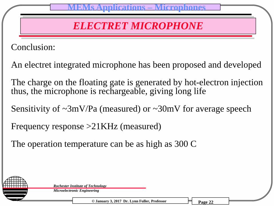
Conclusion:
An electret integrated microphone has been proposed and developed
The charge on the floating gate is generated by hot-electron injection thus, the microphone is rechargeable, giving long life
Sensitivity of ~3mV/Pa (measured) or ~30mV for average speech
Frequency response >21KHz (measured)
The operation temperature can be as high as 300 C

© January 3, 2017 Dr. Lynn Fuller, Professor
Rochester Institute of Technology
Microelectronic Engineering
MEMs Applications – Microphones
Page 23
CONDENSER MICROPHONE

© January 3, 2017 Dr. Lynn Fuller, Professor
Rochester Institute of Technology
Microelectronic Engineering
MEMs Applications – Microphones
Page 24
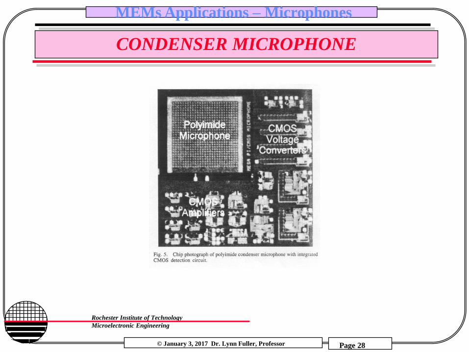
CONDENSER MICROPHONE
Introduction
1. Fabrication is low temperature (<300 C) making this process compatible with post processing of CMOS Amplifier.
2. Both the diaphragm and the backing plate are made of polyimide coated with Cr/Pt/Cr metal and use an aluminum sacrificial layer.
3. Backside etching is done with deep trench plasma etch tool and stops on the Cr/Pt/Cr metal

© January 3, 2017 Dr. Lynn Fuller, Professor
Rochester Institute of Technology
Microelectronic Engineering
MEMs Applications – Microphones
Page 25
CONDENSER MICROPHONE
Backside hole can be etched
in KOH or with plasma
etching

© January 3, 2017 Dr. Lynn Fuller, Professor
Rochester Institute of Technology
Microelectronic Engineering
MEMs Applications – Microphones
Page 26
SIGNAL CONDITIONING
+
9V
-9 V
TL081
i
V
R
CVo
i
i = V Cm 2 p f cos (2pft)Co = Average value of CCm = amplitude of C changeC = Co +Cm sin (2pft)V is constant across C
Vo = - i R
i = d (CV)/dt
Vo = - 2pf V R Cm cos (2pft)
amplitude of Vo

© January 3, 2017 Dr. Lynn Fuller, Professor
Rochester Institute of Technology
Microelectronic Engineering
MEMs Applications – Microphones
Page 27
CONDENSER MICROPHONE
© January 3, 2017 Dr. Lynn Fuller, Professor
Rochester Institute of Technology
Microelectronic Engineering
MEMs Applications – Microphones
Page 28
CONDENSER MICROPHONE
© January 3, 2017 Dr. Lynn Fuller, Professor
Rochester Institute of Technology
Microelectronic Engineering
MEMs Applications – Microphones
Page 29
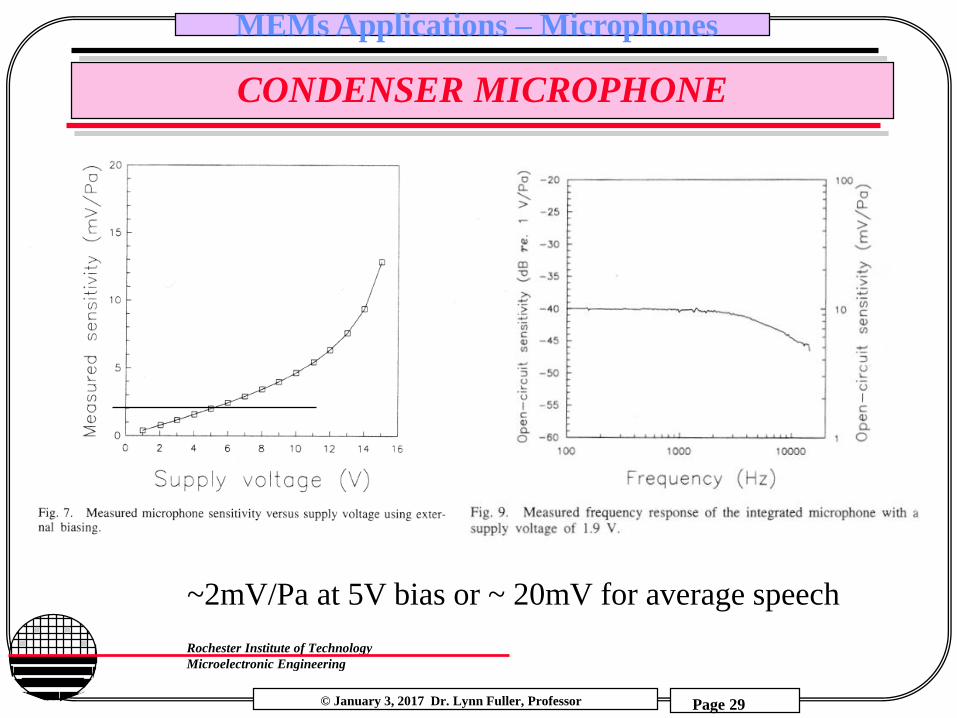
CONDENSER MICROPHONE
~2mV/Pa at 5V bias or ~ 20mV for average speech

© January 3, 2017 Dr. Lynn Fuller, Professor
Rochester Institute of Technology
Microelectronic Engineering
MEMs Applications – Microphones
Page 30
CONDENSER MICROPHONE
Conclusion:
CMOS compatible microphone process
Low temperature process
Sensitivity ~2mV/Pa at 5V bias
Frequency response flat to f > 20KHz

© January 3, 2017 Dr. Lynn Fuller, Professor
Rochester Institute of Technology
Microelectronic Engineering
MEMs Applications – Microphones
Page 31
POLYSILICON DIAPHRAGM MICROPHONE

© January 3, 2017 Dr. Lynn Fuller, Professor
Rochester Institute of Technology
Microelectronic Engineering
MEMs Applications – Microphones
Page 32
POLYSILICON DIAPHRAGM MICROPHONE

© January 3, 2017 Dr. Lynn Fuller, Professor
Rochester Institute of Technology
Microelectronic Engineering
MEMs Applications – Microphones
Page 33
POLYSILICON DIAPHRAGM MICROPHONE
© January 3, 2017 Dr. Lynn Fuller, Professor
Rochester Institute of Technology
Microelectronic Engineering
MEMs Applications – Microphones
Page 34
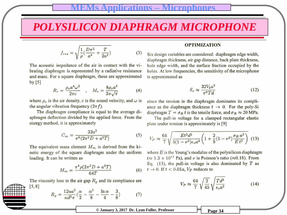
POLYSILICON DIAPHRAGM MICROPHONE

© January 3, 2017 Dr. Lynn Fuller, Professor
Rochester Institute of Technology
Microelectronic Engineering
MEMs Applications – Microphones
Page 35
POLYSILICON DIAPHRAGM MICROPHONE

© January 3, 2017 Dr. Lynn Fuller, Professor
Rochester Institute of Technology
Microelectronic Engineering
MEMs Applications – Microphones
Page 36
POLYSILICON DIAPHRAGM MICROPHONE

© January 3, 2017 Dr. Lynn Fuller, Professor
Rochester Institute of Technology
Microelectronic Engineering
MEMs Applications – Microphones
Page 37
POLYSILICON DIAPHRAGM MICROPHONE

© January 3, 2017 Dr. Lynn Fuller, Professor
Rochester Institute of Technology
Microelectronic Engineering
MEMs Applications – Microphones
Page 38
POLYSILICON DIAPHRAGM MICROPHONE

© January 3, 2017 Dr. Lynn Fuller, Professor
Rochester Institute of Technology
Microelectronic Engineering
MEMs Applications – Microphones
Page 39
POLYSILICON DIAPHRAGM MICROPHONE

© January 3, 2017 Dr. Lynn Fuller, Professor
Rochester Institute of Technology
Microelectronic Engineering
MEMs Applications – Microphones
Page 40
POLYSILICON DIAPHRAGM MICROPHONE

© January 3, 2017 Dr. Lynn Fuller, Professor
Rochester Institute of Technology
Microelectronic Engineering
MEMs Applications – Microphones
Page 41
POLYSILICON DIAPHRAGM MICROPHONE

© January 3, 2017 Dr. Lynn Fuller, Professor
Rochester Institute of Technology
Microelectronic Engineering
MEMs Applications – Microphones
Page 42
MEMS CONDENSER MICROPHONE

© January 3, 2017 Dr. Lynn Fuller, Professor
Rochester Institute of Technology
Microelectronic Engineering
MEMs Applications – Microphones
Page 43
MEMS CONDENSER MICROPHONE

© January 3, 2017 Dr. Lynn Fuller, Professor
Rochester Institute of Technology
Microelectronic Engineering
MEMs Applications – Microphones
Page 44
MEMS CONDENSER MICROPHONE

© January 3, 2017 Dr. Lynn Fuller, Professor
Rochester Institute of Technology
Microelectronic Engineering
MEMs Applications – Microphones
Page 45
MEMS MICROPHONE WITH BACKPLATE SUPPORT

© January 3, 2017 Dr. Lynn Fuller, Professor
Rochester Institute of Technology
Microelectronic Engineering
MEMs Applications – Microphones
Page 46
MEMS MICROPHONE WITH BACKPLATE SUPPORT

© January 3, 2017 Dr. Lynn Fuller, Professor
Rochester Institute of Technology
Microelectronic Engineering
MEMs Applications – Microphones
Page 47
MEMS MICROPHONE WITH BACKPLATE SUPPORT

© January 3, 2017 Dr. Lynn Fuller, Professor
Rochester Institute of Technology
Microelectronic Engineering
MEMs Applications – Microphones
Page 48
MEMS MICROPHONE WITH BACKPLATE SUPPORT

© January 3, 2017 Dr. Lynn Fuller, Professor
Rochester Institute of Technology
Microelectronic Engineering
MEMs Applications – Microphones
Page 49
MEMS CMOS MICROPHONE – METAL DIAPHRAGM

© January 3, 2017 Dr. Lynn Fuller, Professor
Rochester Institute of Technology
Microelectronic Engineering
MEMs Applications – Microphones
Page 50
MEMS CMOS MICROPHONE – METAL DIAPHRAGM

© January 3, 2017 Dr. Lynn Fuller, Professor
Rochester Institute of Technology
Microelectronic Engineering
MEMs Applications – Microphones
Page 51
MEMS CMOS MICROPHONE – METAL DIAPHRAGM

© January 3, 2017 Dr. Lynn Fuller, Professor
Rochester Institute of Technology
Microelectronic Engineering
MEMs Applications – Microphones
Page 52
MEMS CMOS MICROPHONE – METAL DIAPHRAGM

© January 3, 2017 Dr. Lynn Fuller, Professor
Rochester Institute of Technology
Microelectronic Engineering
MEMs Applications – Microphones
Page 53
COMMERCIAL MICROPHONES
Akustica
Analog Devices
Boesch
Emkay Sisonic
Futurlec
Infineon
Knowles
Motorola
STMicroelectronics
TI
Others

© January 3, 2017 Dr. Lynn Fuller, Professor
Rochester Institute of Technology
Microelectronic Engineering
MEMs Applications – Microphones
Page 54
YOLE CONSULTING REPORTS

© January 3, 2017 Dr. Lynn Fuller, Professor
Rochester Institute of Technology
Microelectronic Engineering
MEMs Applications – Microphones
Page 55
AKU1126 MICROPHONES

© January 3, 2017 Dr. Lynn Fuller, Professor
Rochester Institute of Technology
Microelectronic Engineering
MEMs Applications – Microphones
Page 56
AKU1126 MICROPHONE
© January 3, 2017 Dr. Lynn Fuller, Professor
Rochester Institute of Technology
Microelectronic Engineering
MEMs Applications – Microphones
Page 57
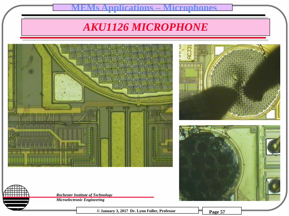
AKU1126 MICROPHONE

© January 3, 2017 Dr. Lynn Fuller, Professor
Rochester Institute of Technology
Microelectronic Engineering
MEMs Applications – Microphones
Page 58
REFERENCES
1. “Microsensors,” Muller, Howe, Senturia, Smith and White, IEEE Press, NY, NY 1991.
2. “Sensor Technology and Devices,” Ristic, L.J., Artech House, London, 1994
3. Journal of Microelectromechanical Systems, IEEE

© January 3, 2017 Dr. Lynn Fuller, Professor
Rochester Institute of Technology
Microelectronic Engineering
MEMs Applications – Microphones
Page 59
HOMEWORK – MICROPHONES
1. What is the difference between a condenser microphone and an electret microphone?
2. Why are there holes in the backing plate in a MEMS microphone?
3. Use the Diaphragm spread sheet to calculate the capacitance change and resonant frequency for a capacitive microphone with the following: 1000um diameter silicon diaphragm, 1.5um gap. You may pick the other parameters you need.
4. The Paper above from Analog devices uses a plate held by springs. Estimate the capacitance change for sound pressures for normal speech.
5. Grad Students Only: Find another publication describing the fabrication of a MEMs pressure sensor (or microphone). Describe the fabrication sequence in your own words. Attach a copy of the paper.
Related Documents