MICE CM30 7 th July 2011 Liquid Hydrogen Delivery System M Hills (STFC, RAL) T Bradshaw (STFC, RAL) M Courthold (STFC, RAL) S Ishimoto (KEK) A Muir (STFC, DL) I Mullacrane (STFC, DL) S Postlethwaite (STFC, DL) J Tarrant (STFC, RAL) P Warburton (STFC, DL)

MICE CM30 7 th July 2011 Liquid Hydrogen Delivery System M Hills (STFC, RAL) T Bradshaw (STFC, RAL) M Courthold (STFC, RAL) S Ishimoto (KEK) A Muir (STFC,
Dec 26, 2015
Welcome message from author
This document is posted to help you gain knowledge. Please leave a comment to let me know what you think about it! Share it to your friends and learn new things together.
Transcript
MICE CM307th July 2011
Liquid Hydrogen Delivery System
M Hills (STFC, RAL)T Bradshaw (STFC, RAL)M Courthold (STFC, RAL)S Ishimoto (KEK)A Muir (STFC, DL)I Mullacrane (STFC, DL)S Postlethwaite (STFC, DL)J Tarrant (STFC, RAL)P Warburton (STFC, DL)
MICE CM307th July 2011
2
Contents
1. Hydrogen System installation progress2. Testing of the R&D system with helium3. Safety 4. Absorber status5. Some thoughts on STEPIV running6. Preparation for AFC#1 and STEP IV7. Milestones8. Summary
2
MICE CM307th July 2011
3
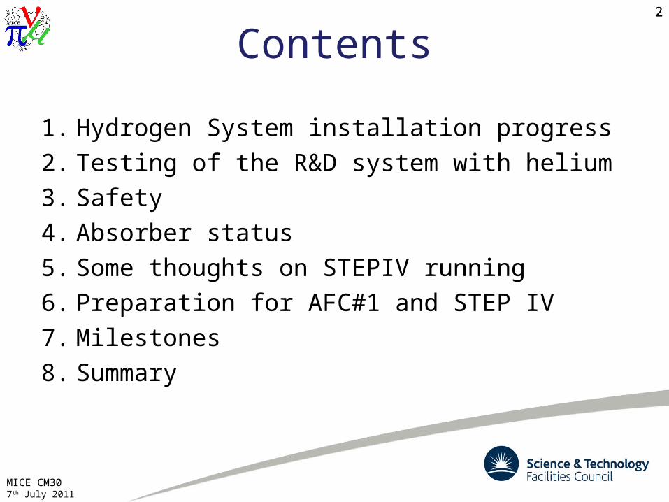
Hydrogen System
3
Relief lines
Ventilation ducts
Fans
Test Cryostat
Gas Panel Enclosures
MICE CM307th July 2011
4
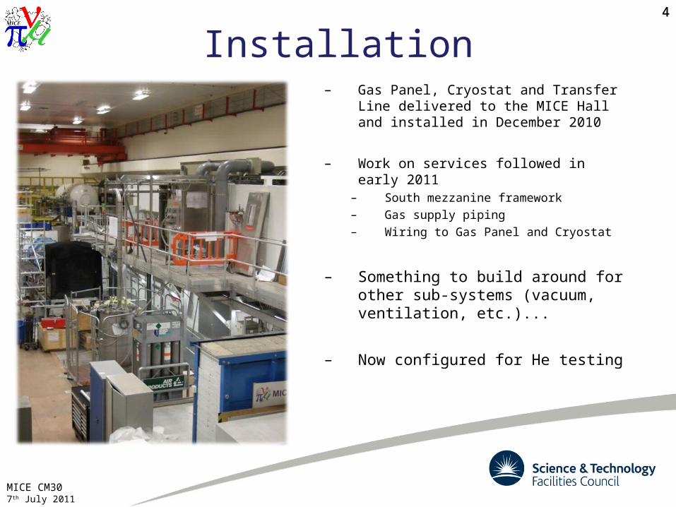
Installation– Gas Panel, Cryostat and Transfer
Line delivered to the MICE Hall and installed in December 2010
– Work on services followed in early 2011
– South mezzanine framework– Gas supply piping– Wiring to Gas Panel and Cryostat
– Something to build around for other sub-systems (vacuum, ventilation, etc.)...
– Now configured for He testing
4
MICE CM307th July 2011
5
Control System(I Mullacrane, P Warburton)
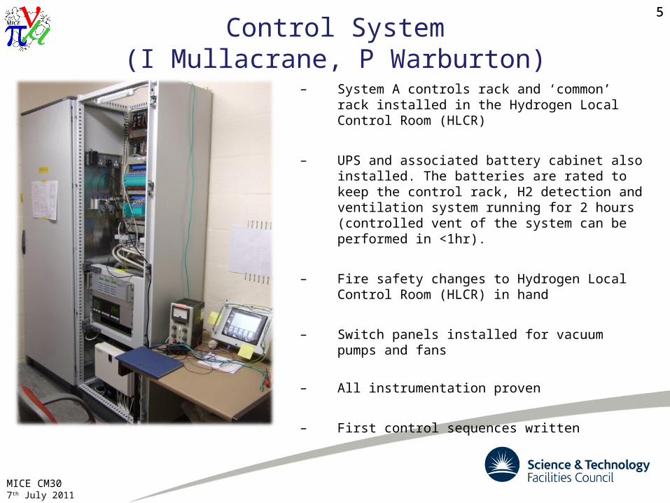
– System A controls rack and ‘common’ rack installed in the Hydrogen Local Control Room (HLCR)
– UPS and associated battery cabinet also installed. The batteries are rated to keep the control rack, H2 detection and ventilation system running for 2 hours (controlled vent of the system can be performed in <1hr).
– Fire safety changes to Hydrogen Local Control Room (HLCR) in hand
– Switch panels installed for vacuum pumps and fans
– All instrumentation proven
– First control sequences written
5
MICE CM307th July 2011
6
Ventilation System
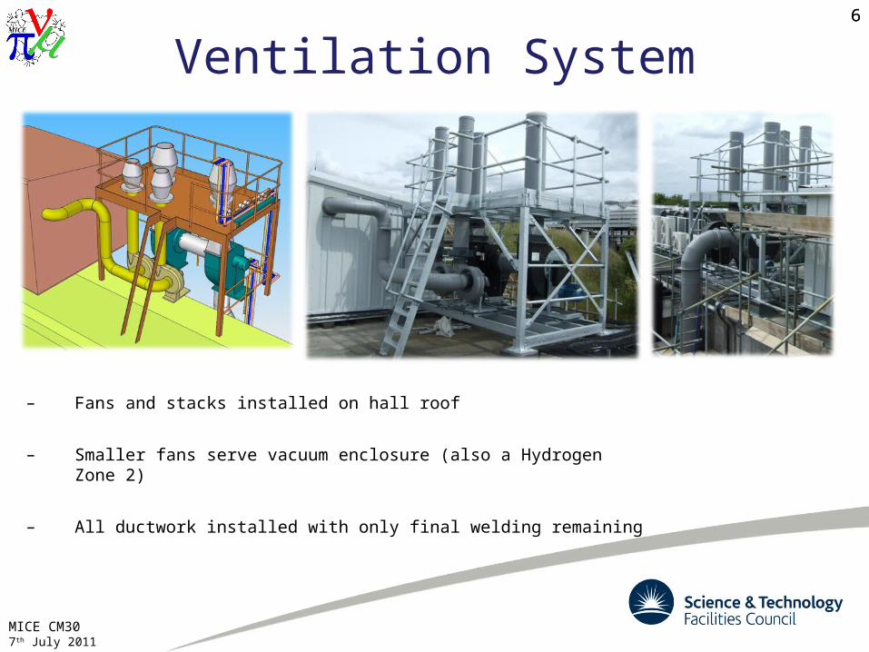
– Fans and stacks installed on hall roof
– Smaller fans serve vacuum enclosure (also a Hydrogen Zone 2)
– All ductwork installed with only final welding remaining
6
MICE CM307th July 2011
7
H2 Charging Station
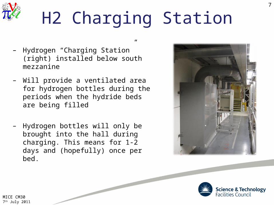
– Hydrogen “Charging Station” (right) installed below south mezzanine
– Will provide a ventilated area for hydrogen bottles during the periods when the hydride beds are being filled
– Hydrogen bottles will only be brought into the hall during charging. This means for 1-2 days and (hopefully) once per bed.
MICE CM307th July 2011
8
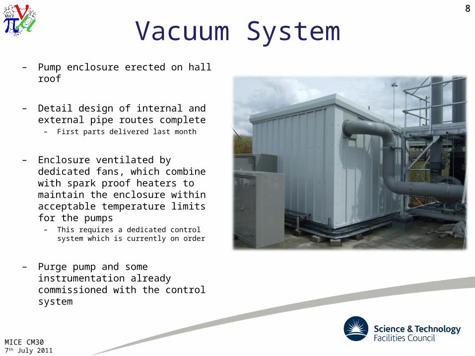
Vacuum System– Pump enclosure erected on hall
roof
– Detail design of internal and external pipe routes complete
– First parts delivered last month
– Enclosure ventilated by dedicated fans, which combine with spark proof heaters to maintain the enclosure within acceptable temperature limits for the pumps
– This requires a dedicated control system which is currently on order
– Purge pump and some instrumentation already commissioned with the control system
8
MICE CM307th July 2011
9
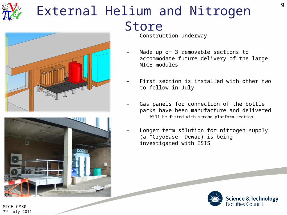
External Helium and Nitrogen Store– Construction underway
– Made up of 3 removable sections to accommodate future delivery of the large MICE modules
– First section is installed with other two to follow in July
– Gas panels for connection of the bottle packs have been manufacture and delivered
– Will be fitted with second platform section
– Longer term solution for nitrogen supply (a “CryoEase” Dewar) is being investigated with ISIS
9
MICE CM307th July 2011
10
Testing Preparations
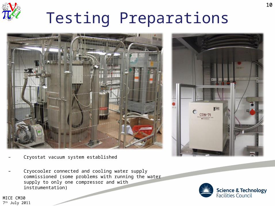
– Cryostat vacuum system established
– Cryocooler connected and cooling water supply commissioned (some problems with running the water supply to only one compressor and with instrumentation)
10
MICE CM307th July 2011
11
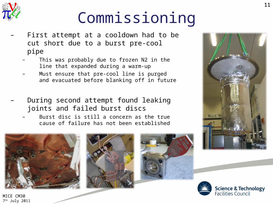
Commissioning– First attempt at a cooldown had to be cut
short due to a burst pre-cool pipe– This was probably due to frozen N2 in the line that
expanded during a warm-up– Must ensure that pre-cool line is purged and
evacuated before blanking off in future
– During second attempt found leaking joints and failed burst discs
– Burst disc is still a concern as the true cause of failure has not been established
11
MICE CM307th July 2011
12
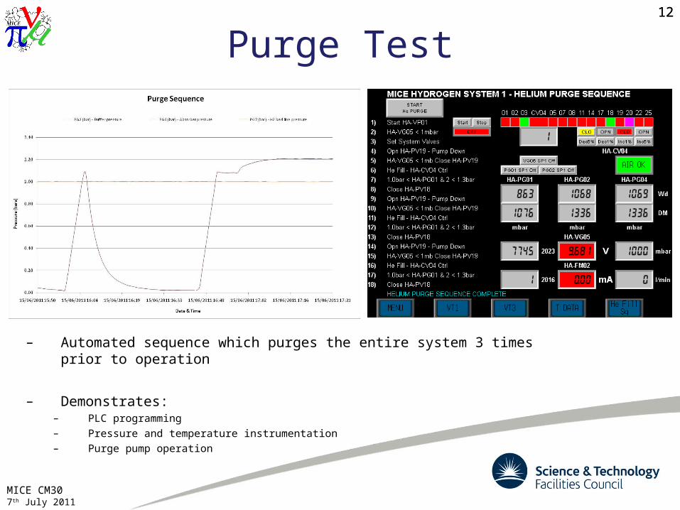
Purge Test
– Automated sequence which purges the entire system 3 times prior to operation
– Demonstrates:– PLC programming– Pressure and temperature instrumentation– Purge pump operation
12

MICE CM307th July 2011
13
Cooldown13
MICE CM307th July 2011
14
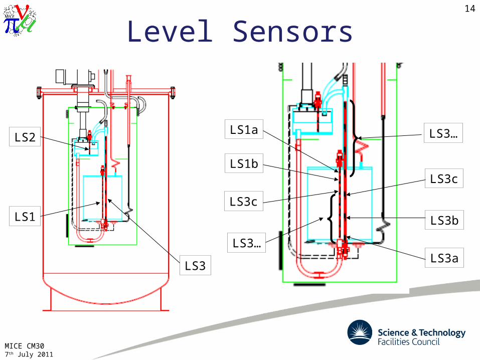
Level Sensors
LS1
LS2
LS3LS3a
LS3b
LS3c
LS3…LS1a
LS1b
LS3c
LS3…
MICE CM307th July 2011
15
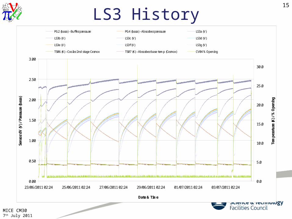
LS3 History
0.00
0.50
1.00
1.50
2.00
2.50
3.00
23/06/2011 02:24 25/06/2011 02:24 27/06/2011 02:24 29/06/2011 02:24 01/07/2011 02:24 03/07/2011 02:24
Date & Time
Sens
or d
V (V
) / P
ress
ure
(bar
a)
0.0
5.0
10.0
15.0
20.0
25.0
30.0
Tem
pera
ture
(K) /
% O
peni
ng
PG2 (bara) - Buffer pressure PG4 (bara) - Absorber pressure LS3a (V)
LS3b (V) LS3c (V) LS3d (V)
LS3e (V) LS3f (V) LS3g (V)
TS06 (K) - Cooler 2nd stage Cernox TS07 (K) - Absorber base temp (Cernox) CV04 % Opening

MICE CM307th July 2011
16
LS1 History
0.00
0.50
1.00
1.50
2.00
2.50
3.00
04/07/2011 07:12 04/07/2011 19:12 05/07/2011 07:12 05/07/2011 19:12 06/07/2011 07:12
Date & Time
Sens
or d
V (V
) / P
ress
ure
(bar
a)
0.0
5.0
10.0
15.0
20.0
25.0
30.0
Tem
pera
ture
(K) /
% O
peni
ng
PG2 (bara) - Buffer pressure PG4 (bara) - Absorber pressure LS1a (V)
LS1b (V) LS1c (V) LS1d (V)
LS1e (V) LS1f (V) LS1g (V)
TS06 (K) - Cooler 2nd stage Cernox TS07 (K) - Absorber base temp (Cernox) CV04 % Opening

MICE CM307th July 2011
17
Testing Status– Cryostat is stable at 4K
– Some helium liquefaction, but rate difficult to quantify at this stage
– Will run the test as long as possible before EMR running prevents hall access
– Confirm long term stability – Give water system an extended test– Investigate level sensor performance more fully– Collect other data to estimate liquefaction rate– Test warm-up sequence
17
MICE CM307th July 2011
18
Safety– UPS case agreed within the project and system now installed
– Ventilation system and all fans have been shown to comply with DSEAR (confirmed with external consultation)
– IEC61508 compliance being developed with help of a specialist company (Functional Safety Consultancy Ltd)
– Discussions on pre-operation safety review continuing with ISIS and it is converging on an appropriate format and membership
– Work on this has been held back at the expense of the recent test programme, but the focus will shift back in the next month
– Safety principles have been well established for some time, but it is important that the detail of their implementation is approved
18
MICE CM307th July 2011
19
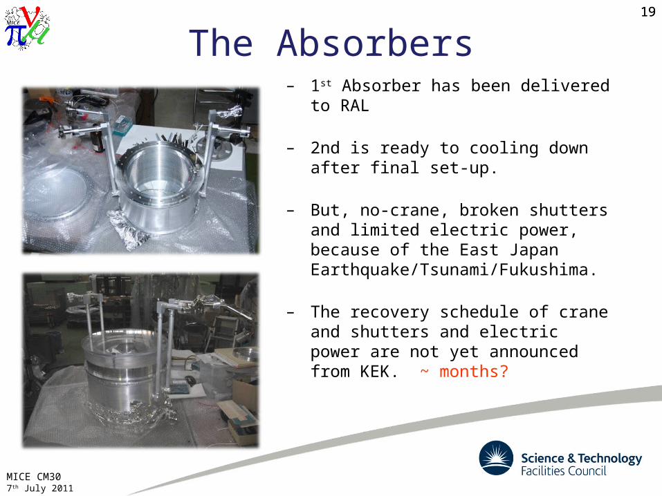
– 1st Absorber has been delivered to RAL
– 2nd is ready to cooling down after final set-up.
– But, no-crane, broken shutters and limited electric power, because of the East Japan Earthquake/Tsunami/Fukushima.
– The recovery schedule of crane and shutters and electric power are not yet announced from KEK. ~ months?
The Absorbers19
MICE CM307th July 2011
20
Hydrogen Liquefaction20
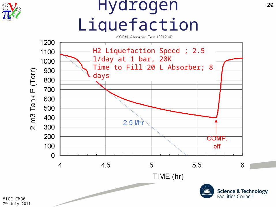
H2 Liquefaction Speed ; 2.5 l/day at 1 bar, 20KTime to Fill 20 L Absorber; 8 days
MICE CM307th July 2011
21
STEP IV Running Thoughts– Absorber cooldown time: 1 day with LN2 pre-cool (both for KEK Absorber
and R&D system)
– Helium liquefaction should be possible, but will take many days (exact time TBC)
– Filling from an LHe Dewar will require removal of the hydrogen transfer line
– Hydrogen liquefaction is reasonable (8 days?)
– Hydride Bed absorption and desorption rates from testing at the manufacturer: 50L/min
– Absorber fill is limited by cryogenic power– Absorber empty will be approx 350min (~6hrs)– BUT, 50L/min was the limit of the manufacturer’s measuring equipment
Confirming these things is what the Hydrogen R&D is all about…
MICE CM307th July 2011
22
Towards AFC#1 and STEPIV– Final hurdle for System A is to commission it with the first AFC module
– Good links with Tesla and the AFC team, but this will become more crucial as the AFC progress
– Sufficient engineering effort must be devoted to it to avoid problems later
– Current plan is to commission the absorber with the AFC, but this depends on the AFC schedule.
– If the AFC is delayed it may be useful to reconfigure the test cryostat for absorber testing
– It is currently envisaged to relocate the Gas Panel Enclosure to the East end of the mezzanine for STEPIV
– New transfer lines and vacuum pipes need to be manufactured and installed for the AFC, and these must be compatible with the later installations
– Mezzanine modifications currently being designed– Need to consider a helium fill from a Dewar
22
MICE CM307th July 2011
23
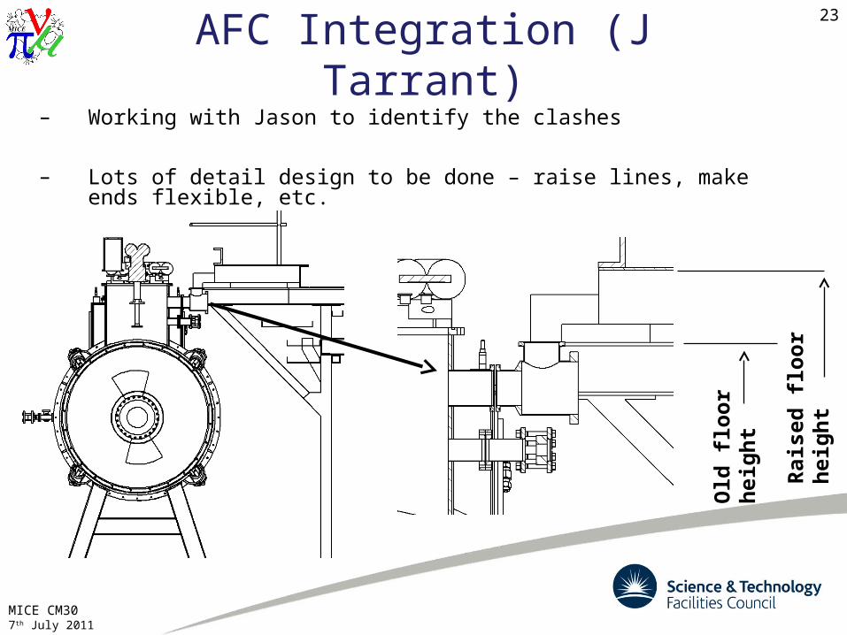
AFC Integration (J Tarrant)– Working with Jason to identify the clashes
– Lots of detail design to be done – raise lines, make ends flexible, etc.
Old
flo
or
hei
gh
t
Rai
sed
flo
or
hei
gh
t
MICE CM307th July 2011
24
Milestones24
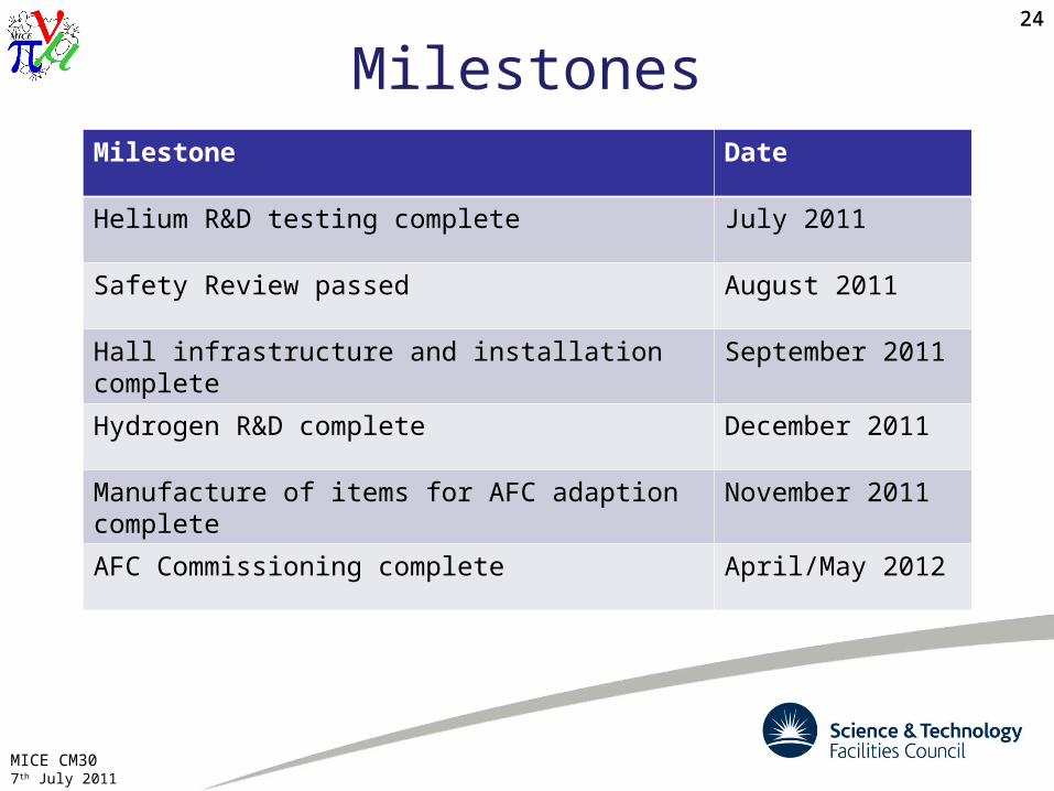
Milestone Date
Helium R&D testing complete July 2011
Safety Review passed August 2011
Hall infrastructure and installation complete September 2011
Hydrogen R&D complete December 2011
Manufacture of items for AFC adaption complete
November 2011
AFC Commissioning complete April/May 2012
MICE CM307th July 2011
25
Summary and forward look– Installation of the Hydrogen Delivery System infrastructure is well
advanced and progressing well
– Testing of the system with helium is underway with promising results
– First absorber has been delivered to RAL
– Primary absorber windows are ready for shipping after QA
– Aim to complete R&D with hydrogen by the end of 2011, depending on EMR running
– Planning for STEPIV is significantly dependent on the AFC schedule and closer working with Tesla will be important in the coming months
– Research into the hydride beds for Systems B&C should begin as soon as possible
25
Related Documents