Quick Start Guide www.zyxel.com MGS3750-28F MetroGigabit Switch Version 1.02 Edition 2, 11/2016 Copyright © 2016 ZyXEL Communications Corporation User’s Guide Default Login Details IP Address http://192.168.1.1 User Name admin Password 1234

Welcome message from author
This document is posted to help you gain knowledge. Please leave a comment to let me know what you think about it! Share it to your friends and learn new things together.
Transcript
Quick Start Guide
www.zyxel.com
MGS3750-28FMetroGigabit Switch
Version 1.02Edition 2, 11/2016
Copyright © 2016 ZyXEL Communications Corporation
User’s Guide
Default Login DetailsIP Address http://192.168.1.1User Name adminPassword 1234
MGS3750-28F User’s Guide
2
IMPORTANT!
READ CAREFULLY BEFORE USE.
KEEP THIS GUIDE FOR FUTURE REFERENCE.
Note: This guide is a reference for a series of products. Therefore some features or options in this guide may not be available in your product.
Screenshots and graphics in this book may differ slightly from your product due to differences in your product firmware or your computer operating system. Every effort has been made to ensure that the information in this manual is accurate.
Related Documentation
• CLI Reference Guide
The CLI Reference Guide explains how to use the Command-Line Interface (CLI) and CLI commands to configure the Switch.
• More Information
Go to support.zyxel.com to find other information on the Switch.
Contents Overview
MGS3750-28F User’s Guide
3
Contents Overview
Hardware Installation and Connection ......................................................................................................7
Hardware Overview .................................................................................................................................10
Logging into the Web Interface ...............................................................................................................15
Overall Web Page Layout .......................................................................................................................16
Basic Settings .........................................................................................................................................18
Advanced Application Configurations .....................................................................................................22
Management ...........................................................................................................................................61
Table of Contents
MGS3750-28F User’s Guide
4
Table of Contents
Contents Overview ..............................................................................................................................3
Table of Contents .................................................................................................................................4
Chapter 1Hardware Installation and Connection ...............................................................................................7
1.1 Installation Scenarios ..........................................................................................................................7
1.2 Desktop Installation Procedure ..........................................................................................................7
1.3 Mounting the Switch on a Rack ..........................................................................................................7
1.3.1 Rack-mounted Installation Requirements ..................................................................................7
1.3.2 Attaching the Mounting Brackets to the Switch .........................................................................8
1.3.3 Mounting the Switch on a Rack .................................................................................................8
Chapter 2Hardware Overview ............................................................................................................................10
2.1 Front Panel .......................................................................................................................................10
2.1.1 Console Port ............................................................................................................................10
2.1.2 Transceiver Slots ..................................................................................................................... 11
2.1.3 Power Connector .....................................................................................................................13
2.2 LEDs ................................................................................................................................................14
Chapter 3Logging into the Web Interface .........................................................................................................15
3.1 Launch Browser ................................................................................................................................15
Chapter 4Overall Web Page Layout...................................................................................................................16
4.1 Port Status .........................................................................................................................................16
Chapter 5Basic Settings .....................................................................................................................................18
5.1 System Info .......................................................................................................................................18
5.2 General Application ...........................................................................................................................19
5.3 IP Setup ............................................................................................................................................20
5.4 Port Setup .........................................................................................................................................20
Chapter 6Advanced Application Configurations .............................................................................................22
6.1 VLAN .................................................................................................................................................22
6.1.1 VLAN Status ............................................................................................................................22
Table of Contents
MGS3750-28F User’s Guide
5
6.1.2 VLAN Port Settings ..................................................................................................................23
6.1.3 Static VLAN .............................................................................................................................24
6.2 Static Mac Forwarding .......................................................................................................................25
6.3 Spanning Tree Protocol .....................................................................................................................27
6.3.1 Spanning Tree Configuration ...................................................................................................28
6.3.2 Compatible/Rapid Spanning Tree Protocol ..............................................................................29
6.3.3 Multiple Spanning Tree Protocol ..............................................................................................31
6.4 ERPS Protocol ..................................................................................................................................33
6.4.1 Instance Screen .......................................................................................................................34
6.5 EAPS Protocol ..................................................................................................................................34
6.6 Layer 2 Protocol Tunnel ....................................................................................................................37
6.7 Bandwidth Control .............................................................................................................................38
6.8 Broadcast Storm Control ...................................................................................................................39
6.9 Mirroring ............................................................................................................................................40
6.10 Link Aggregation .............................................................................................................................41
6.10.1 Link Aggregation Setting .......................................................................................................42
6.10.2 Link Aggregation Control Protocol .........................................................................................44
6.10.3 Group ID ................................................................................................................................44
6.10.4 Port ........................................................................................................................................45
6.11 Port Security ....................................................................................................................................45
6.12 Classifier .........................................................................................................................................47
6.13 Policy Rule ......................................................................................................................................50
6.14 Queuing Method ..............................................................................................................................52
6.15 Multicast ..........................................................................................................................................53
6.15.1 Multicast Setting ....................................................................................................................54
6.15.2 IGMP Snooping Deny VLAN .................................................................................................55
6.15.3 IGMP Filtering Profile ............................................................................................................56
6.16 CPU Queue Control ........................................................................................................................57
6.17 DoS Attack Control ..........................................................................................................................58
Chapter 7Management........................................................................................................................................61
7.1 Maintenance ......................................................................................................................................61
7.1.1 Firmware Upgrade ...................................................................................................................61
7.1.2 Restart System ........................................................................................................................62
7.1.3 OAM Diag ................................................................................................................................63
7.2 Access Control ..................................................................................................................................63
7.2.1 SNMP ......................................................................................................................................64
7.2.2 User Information ......................................................................................................................65
7.2.3 Logins ......................................................................................................................................67
7.3 Diagnostic .........................................................................................................................................68
7.4 Syslog Setup .....................................................................................................................................68
7.4.1 Syslog Server Setup ................................................................................................................69

Table of Contents
MGS3750-28F User’s Guide
6
Appendix A Customer Support ..........................................................................................................71
Appendix B Legal Information............................................................................................................77
MGS3750-28F User’s Guide
7
CHAPTER 1
Hardware Installation and Connection
This chapter shows you how to install and connect the Switch.
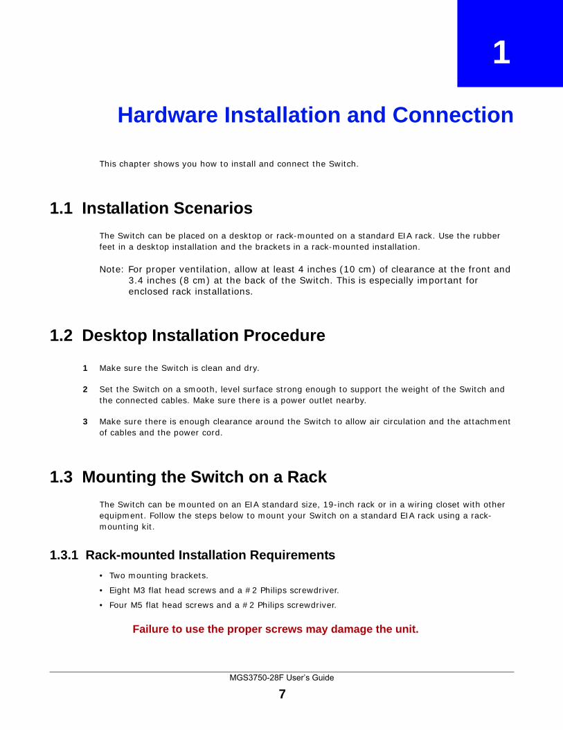
1.1 Installation Scenarios
The Switch can be placed on a desktop or rack-mounted on a standard EIA rack. Use the rubber feet in a desktop installation and the brackets in a rack-mounted installation.
Note: For proper ventilation, allow at least 4 inches (10 cm) of clearance at the front and 3.4 inches (8 cm) at the back of the Switch. This is especially important for enclosed rack installations.
1.2 Desktop Installation Procedure
1 Make sure the Switch is clean and dry.
2 Set the Switch on a smooth, level surface strong enough to support the weight of the Switch and the connected cables. Make sure there is a power outlet nearby.
3 Make sure there is enough clearance around the Switch to allow air circulation and the attachment of cables and the power cord.
1.3 Mounting the Switch on a Rack
The Switch can be mounted on an EIA standard size, 19-inch rack or in a wiring closet with other equipment. Follow the steps below to mount your Switch on a standard EIA rack using a rack-mounting kit.
1.3.1 Rack-mounted Installation Requirements
• Two mounting brackets.
• Eight M3 flat head screws and a #2 Philips screwdriver.
• Four M5 flat head screws and a #2 Philips screwdriver.
Failure to use the proper screws may damage the unit.
Chapter 1 Hardware Installation and Connection
MGS3750-28F User’s Guide
8
1.3.1.1 Precautions • Make sure the rack will safely support the combined weight of all the equipment it contains.
• Make sure the position of the Switch does not make the rack unstable or top-heavy. Take all necessary precautions to anchor the rack securely before installing the unit.
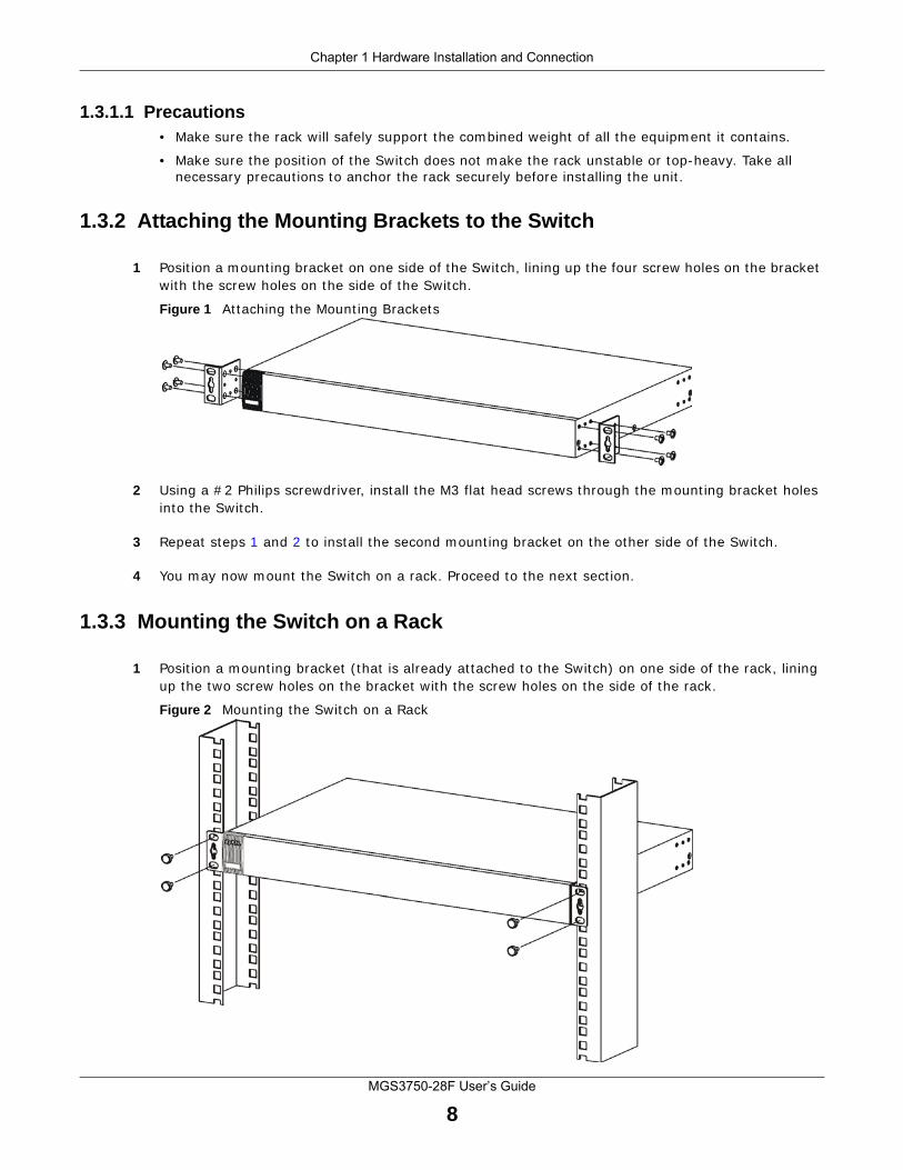
1.3.2 Attaching the Mounting Brackets to the Switch
1 Position a mounting bracket on one side of the Switch, lining up the four screw holes on the bracket with the screw holes on the side of the Switch.
Figure 1 Attaching the Mounting Brackets
2 Using a #2 Philips screwdriver, install the M3 flat head screws through the mounting bracket holes into the Switch.
3 Repeat steps 1 and 2 to install the second mounting bracket on the other side of the Switch.
4 You may now mount the Switch on a rack. Proceed to the next section.
1.3.3 Mounting the Switch on a Rack
1 Position a mounting bracket (that is already attached to the Switch) on one side of the rack, lining up the two screw holes on the bracket with the screw holes on the side of the rack.
Figure 2 Mounting the Switch on a Rack

Chapter 1 Hardware Installation and Connection
MGS3750-28F User’s Guide
9
2 Using a #2 Philips screwdriver, install the M5 flat head screws through the mounting bracket holes into the rack.
3 Repeat steps 1 and 2 to attach the second mounting bracket on the other side of the rack.
MGS3750-28F User’s Guide
10
CHAPTER 2
Hardware Overview
This chapter describes the front panel and rear panel of the Switch and shows you how to make the hardware connections.
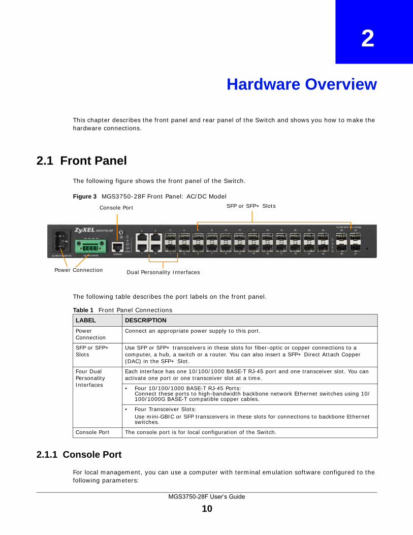
2.1 Front Panel
The following figure shows the front panel of the Switch.
Figure 3 MGS3750-28F Front Panel: AC/DC Model
The following table describes the port labels on the front panel.
2.1.1 Console Port
For local management, you can use a computer with terminal emulation software configured to the following parameters:
Dual Personality Interfaces
SFP or SFP+ SlotsConsole Port
Power Connection
Table 1 Front Panel ConnectionsLABEL DESCRIPTION
Power Connection
Connect an appropriate power supply to this port.
SFP or SFP+ Slots
Use SFP or SFP+ transceivers in these slots for fiber-optic or copper connections to a computer, a hub, a switch or a router. You can also insert a SFP+ Direct Attach Copper (DAC) in the SFP+ Slot.
Four Dual Personality Interfaces
Each interface has one 10/100/1000 BASE-T RJ-45 port and one transceiver slot. You can activate one port or one transceiver slot at a time.
• Four 10/100/1000 BASE-T RJ-45 Ports:Connect these ports to high-bandwidth backbone network Ethernet switches using 10/100/1000G BASE-T compatible copper cables.
• Four Transceiver Slots:Use mini-GBIC or SFP transceivers in these slots for connections to backbone Ethernet switches.
Console Port The console port is for local configuration of the Switch.
Chapter 2 Hardware Overview
MGS3750-28F User’s Guide
11
• VT100
• Terminal emulation
• 115200 bps
• No parity, 8 data bits, 1 stop bit
• No flow control
Connect the male 9-pin end of the console cable to the console port of the Switch. Connect the female end to a serial port (COM1, COM2 or other COM port) of your computer.
2.1.1.1 Default Ethernet Negotiation Settings
The factory default negotiation settings for the Gigabit ports on the Switch are:
• Speed: Auto
• Duplex: Auto
• Flow control: Off
• Link Aggregation: Disabled
2.1.1.2 Auto-crossover
All ports are auto-crossover, that is auto-MDIX ports (Media Dependent Interface Crossover), so you may use either a straight-through Ethernet cable or crossover Ethernet cable for all Gigabit port connections. Auto-crossover ports automatically sense whether they need to function as crossover or straight ports, so crossover cables can connect both computers and switches/hubs.
2.1.2 Transceiver Slots
These are slots for mini-GBIC (Gigabit Interface Converter) transceivers or 100 Mbps Small Form-factor Pluggable (SFP) transceivers. A transceiver is a single unit that houses a transmitter and a receiver. The Switch does not come with transceivers. You must use transceivers that comply with the SFP Transceiver MultiSource Agreement (MSA). See the SFF committee’s INF-8074i specification Rev 1.0 for details.
You can change transceivers while the Switch is operating. You can use different transceivers to connect to Ethernet switches with different types of fiber-optic or even copper cable connectors.
To avoid possible eye injury, do not look into an operating fiber-optic module’s connectors.
• Type: SFP connection interface
• Connection speed: 1 Gigabit per second (Gbps) or 1 Megabit per second (Mbps)
2.1.2.1 Transceiver Installation
Use the following steps to install a mini-GBIC transceiver (SFP module).
1 Insert the transceiver into the slot with the exposed section of PCB board facing down.
2 Press the transceiver firmly until it clicks into place.
Chapter 2 Hardware Overview
MGS3750-28F User’s Guide
12
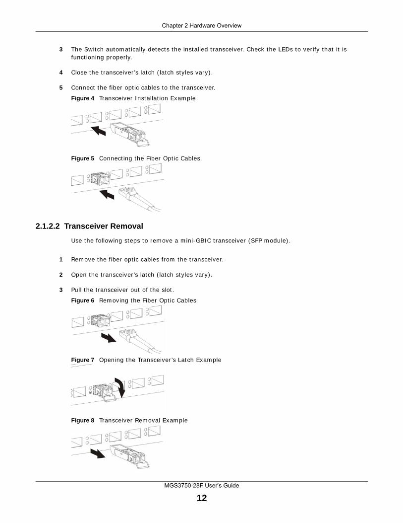
3 The Switch automatically detects the installed transceiver. Check the LEDs to verify that it is functioning properly.
4 Close the transceiver’s latch (latch styles vary).
5 Connect the fiber optic cables to the transceiver.
Figure 4 Transceiver Installation Example
Figure 5 Connecting the Fiber Optic Cables
2.1.2.2 Transceiver Removal
Use the following steps to remove a mini-GBIC transceiver (SFP module).
1 Remove the fiber optic cables from the transceiver.
2 Open the transceiver’s latch (latch styles vary).
3 Pull the transceiver out of the slot.
Figure 6 Removing the Fiber Optic Cables
Figure 7 Opening the Transceiver’s Latch Example
Figure 8 Transceiver Removal Example
Chapter 2 Hardware Overview
MGS3750-28F User’s Guide
13
2.1.3 Power Connector
Make sure you are using the correct power source as shown on the panel and that no objects obstruct the airflow of the fans.
Use the following procedures to connect the Switch to a power source after you have installed it.
Note: Check the power supply requirements on the panel, and make sure you are using an appropriate power source.
Keep the power supply switch and the Switch’s power switch in the OFF position until you come to the procedure for turning on the power.
Use only power wires of the required diameter for connecting the Switch to a power supply.
2.1.3.1 AC Power Connection
Connect the female end of the power cord to the power socket of your Switch. Connect the other end of the cord to a power outlet.
2.1.3.2 DC Power Connection
The Switch uses a single ETB series terminal block plug with four pins which allows you to connect up to two separate power supplies. If one power supply fails the system can operate on the remaining power supply. Use two wires to connect to a single terminal pair, one wire for the positive terminal and one wire for the negative terminal.
Note: The current rating of the power wires must be greater than 20 Amps. The power supply to which the Switch connects must have a built-in circuit breaker or switch to toggle the power.
Note: When installing the power wire, push it firmly into the terminal as deep as possible and make sure that no exposed (bare) wire can be seen or touched.
Exposed power wire is dangerous. Use extreme care when connecting a DC power source to the device.
To connect a power supply:
1 Use a screwdriver to loosen the terminal block captive screws.
2 Connect one end of a power wire to the Switch’s RTN (return) pin and tighten the captive screw.
3 Connect the other end of the power wire to the positive terminal on the power supply.
4 Connect one end of a power wire to the Switch’s -48V (input) pin and tighten the captive screw.
5 Connect the other end of the power wire to the negative terminal on the power supply.
6 Insert the terminal block plug in the Switch’s terminal block header.
Chapter 2 Hardware Overview
MGS3750-28F User’s Guide
14
2.2 LEDs
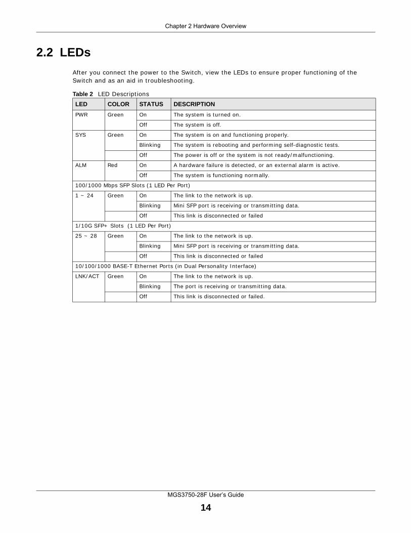
After you connect the power to the Switch, view the LEDs to ensure proper functioning of the Switch and as an aid in troubleshooting.
Table 2 LED DescriptionsLED COLOR STATUS DESCRIPTION
PWR Green On The system is turned on.
Off The system is off.
SYS Green On The system is on and functioning properly.
Blinking The system is rebooting and performing self-diagnostic tests.
Off The power is off or the system is not ready/malfunctioning.
ALM Red On A hardware failure is detected, or an external alarm is active.
Off The system is functioning normally.
100/1000 Mbps SFP Slots (1 LED Per Port)
1 ~ 24 Green On The link to the network is up.
Blinking Mini SFP port is receiving or transmitting data.
Off This link is disconnected or failed
1/10G SFP+ Slots (1 LED Per Port)
25 ~ 28 Green On The link to the network is up.
Blinking Mini SFP port is receiving or transmitting data.
Off This link is disconnected or failed
10/100/1000 BASE-T Ethernet Ports (in Dual Personality Interface)
LNK/ACT Green On The link to the network is up.
Blinking The port is receiving or transmitting data.
Off This link is disconnected or failed.
MGS3750-28F User’s Guide
15
CHAPTER 3
Logging into the Web Interface
3.1 Launch Browser
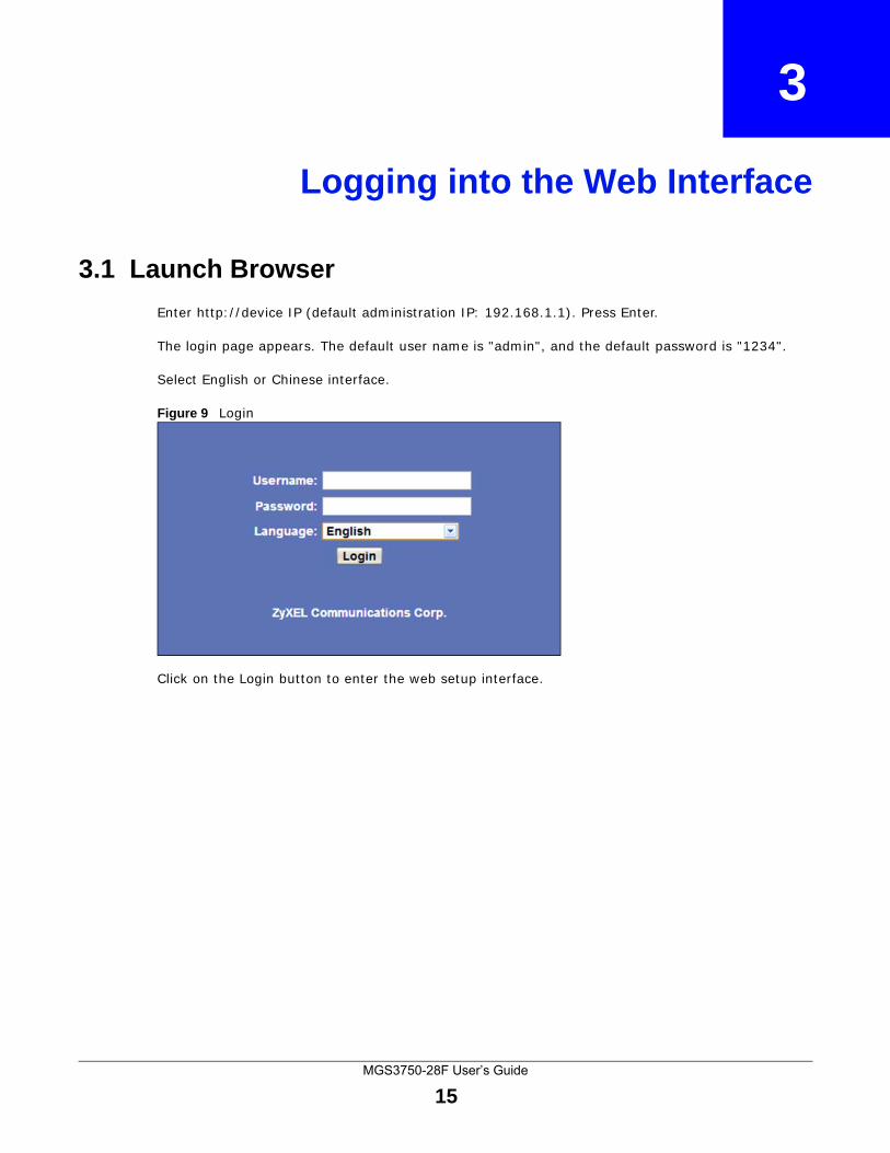
Enter http://device IP (default administration IP: 192.168.1.1). Press Enter.
The login page appears. The default user name is "admin", and the default password is "1234".
Select English or Chinese interface.
Figure 9 Login
Click on the Login button to enter the web setup interface.
MGS3750-28F User’s Guide
16
CHAPTER 4
Overall Web Page Layout
4.1 Port Status
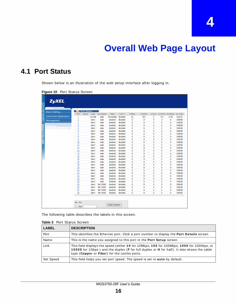
Shown below is an illustration of the web setup interface after logging in.
Figure 10 Port Status Screen
The following table describes the labels in this screen.
Table 3 Port Status ScreenLABEL DESCRIPTION
Port This identifies the Ethernet port. Click a port number to display the Port Details screen.
Name This is the name you assigned to this port in the Port Setup screen.
Link This field displays the speed (either 10 for 10Mbps, 100 for 100Mbps, 1000 for 1000bps, or 10000 for 1Gbps ) and the duplex (F for full duplex or H for half). It also shows the cable type (Copper or Fiber) for the combo ports.
Set Speed This field helps you set port speed. The speed is set to auto by default.
Chapter 4 Overall Web Page Layout
MGS3750-28F User’s Guide
17
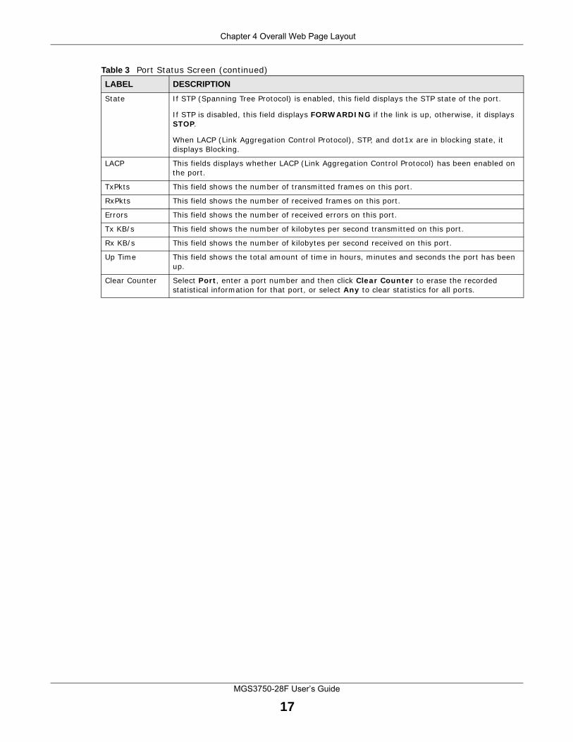
State If STP (Spanning Tree Protocol) is enabled, this field displays the STP state of the port.
If STP is disabled, this field displays FORWARDING if the link is up, otherwise, it displays STOP.
When LACP (Link Aggregation Control Protocol), STP, and dot1x are in blocking state, it displays Blocking.
LACP This fields displays whether LACP (Link Aggregation Control Protocol) has been enabled on the port.
TxPkts This field shows the number of transmitted frames on this port.
RxPkts This field shows the number of received frames on this port.
Errors This field shows the number of received errors on this port.
Tx KB/s This field shows the number of kilobytes per second transmitted on this port.
Rx KB/s This field shows the number of kilobytes per second received on this port.
Up Time This field shows the total amount of time in hours, minutes and seconds the port has been up.
Clear Counter Select Port, enter a port number and then click Clear Counter to erase the recorded statistical information for that port, or select Any to clear statistics for all ports.
Table 3 Port Status Screen (continued)LABEL DESCRIPTION
MGS3750-28F User’s Guide
18
CHAPTER 5
Basic Settings
5.1 System Info
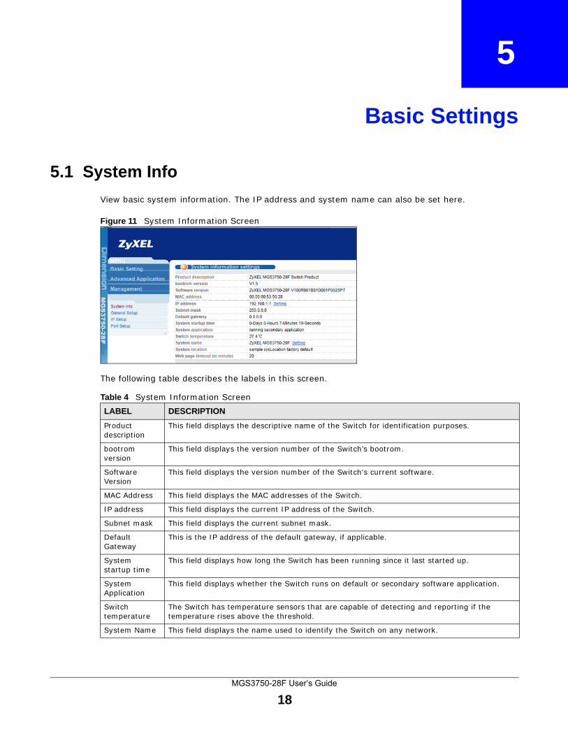
View basic system information. The IP address and system name can also be set here.
Figure 11 System Information Screen
The following table describes the labels in this screen.
Table 4 System Information Screen LABEL DESCRIPTION
Product description
This field displays the descriptive name of the Switch for identification purposes.
bootrom version
This field displays the version number of the Switch’s bootrom.
Software Version
This field displays the version number of the Switch's current software.
MAC Address This field displays the MAC addresses of the Switch.
IP address This field displays the current IP address of the Switch.
Subnet mask This field displays the current subnet mask.
Default Gateway
This is the IP address of the default gateway, if applicable.
System startup time
This field displays how long the Switch has been running since it last started up.
System Application
This field displays whether the Switch runs on default or secondary software application.
Switch temperature
The Switch has temperature sensors that are capable of detecting and reporting if the temperature rises above the threshold.
System Name This field displays the name used to identify the Switch on any network.
Chapter 5 Basic Settings
MGS3750-28F User’s Guide
19
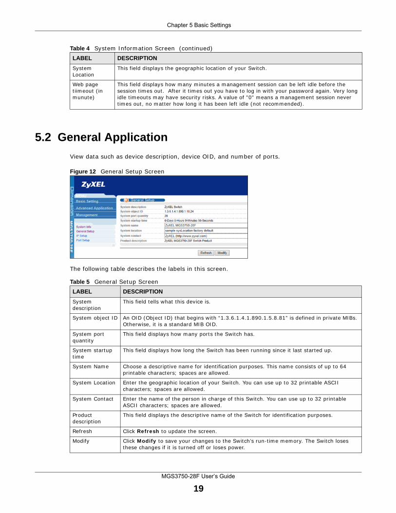
5.2 General Application
View data such as device description, device OID, and number of ports.
Figure 12 General Setup Screen
The following table describes the labels in this screen.
System Location
This field displays the geographic location of your Switch.
Web page tiimeout (in munute)
This field displays how many minutes a management session can be left idle before the session times out. After it times out you have to log in with your password again. Very long idle timeouts may have security risks. A value of "0" means a management session never times out, no matter how long it has been left idle (not recommended).
Table 4 System Information Screen (continued)LABEL DESCRIPTION
Table 5 General Setup Screen LABEL DESCRIPTION
System description
This field tells what this device is.
System object ID An OID (Object ID) that begins with “1.3.6.1.4.1.890.1.5.8.81” is defined in private MIBs. Otherwise, it is a standard MIB OID.
System port quantity
This field displays how many ports the Switch has.
System startup time
This field displays how long the Switch has been running since it last started up.
System Name Choose a descriptive name for identification purposes. This name consists of up to 64 printable characters; spaces are allowed.
System Location Enter the geographic location of your Switch. You can use up to 32 printable ASCII characters; spaces are allowed.
System Contact Enter the name of the person in charge of this Switch. You can use up to 32 printable ASCII characters; spaces are allowed.
Product description
This field displays the descriptive name of the Switch for identification purposes.
Refresh Click Refresh to update the screen.
Modify Click Modify to save your changes to the Switch’s run-time memory. The Switch loses these changes if it is turned off or loses power.
Chapter 5 Basic Settings
MGS3750-28F User’s Guide
20
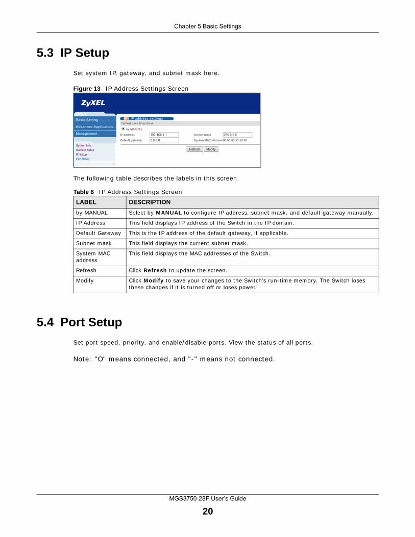
5.3 IP Setup
Set system IP, gateway, and subnet mask here.
Figure 13 IP Address Settings Screen
The following table describes the labels in this screen.
5.4 Port Setup
Set port speed, priority, and enable/disable ports. View the status of all ports.
Note: "O" means connected, and "-" means not connected.
Table 6 IP Address Settings Screen LABEL DESCRIPTION
by MANUAL Select by MANUAL to configure IP address, subnet mask, and default gateway manually.
IP Address This field displays IP address of the Switch in the IP domain.
Default Gateway This is the IP address of the default gateway, if applicable.
Subnet mask This field displays the current subnet mask.
System MAC address
This field displays the MAC addresses of the Switch.
Refresh Click Refresh to update the screen.
Modify Click Modify to save your changes to the Switch’s run-time memory. The Switch loses these changes if it is turned off or loses power.
Chapter 5 Basic Settings
MGS3750-28F User’s Guide
21
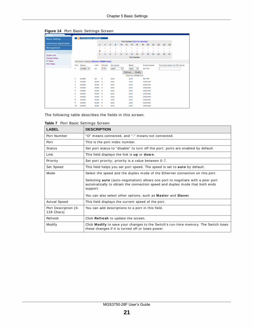
Figure 14 Port Basic Settings Screen
The following table describes the fields in this screen.
Table 7 Port Basic Settings ScreenLABEL DESCRIPTION
Port Number "O" means connected, and "-" means not connected.
Port This is the port index number.
Status Set port status to "disable" to turn off the port; ports are enabled by default.
Link This field displays the link is up or down.
Priority Set port priority; priority is a value between 0-7.
Set Speed This field helps you set port speed. The speed is set to auto by default.
Mode Select the speed and the duplex mode of the Ethernet connection on this port.
Selecting auto (auto-negotiation) allows one port to negotiate with a peer port automatically to obtain the connection speed and duplex mode that both ends support.
You can also select other options, such as Master and Slaver.
Actual Speed This field displays the current speed of the port.
Port Description (0-128 Chars)
You can add descriptions to a port in this field.
Refresh Click Refresh to update the screen.
Modify Click Modify to save your changes to the Switch’s run-time memory. The Switch loses these changes if it is turned off or loses power.
MGS3750-28F User’s Guide
22
CHAPTER 6
Advanced Application Configurations
6.1 VLAN
This chapter shows you how to configure port-based VLANs.
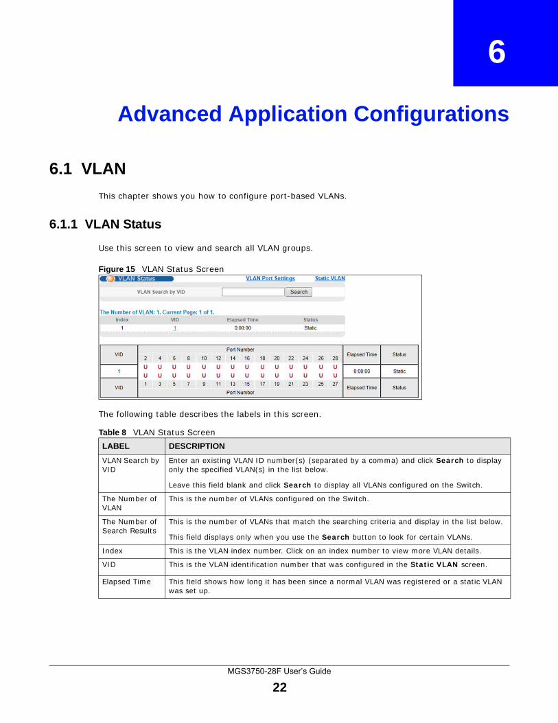
6.1.1 VLAN Status
Use this screen to view and search all VLAN groups.
Figure 15 VLAN Status Screen
The following table describes the labels in this screen.
Table 8 VLAN Status Screen LABEL DESCRIPTION
VLAN Search by VID
Enter an existing VLAN ID number(s) (separated by a comma) and click Search to display only the specified VLAN(s) in the list below.
Leave this field blank and click Search to display all VLANs configured on the Switch.
The Number of VLAN
This is the number of VLANs configured on the Switch.
The Number of Search Results
This is the number of VLANs that match the searching criteria and display in the list below.
This field displays only when you use the Search button to look for certain VLANs.
Index This is the VLAN index number. Click on an index number to view more VLAN details.
VID This is the VLAN identification number that was configured in the Static VLAN screen.
Elapsed Time This field shows how long it has been since a normal VLAN was registered or a static VLAN was set up.
Chapter 6 Advanced Application Configurations
MGS3750-28F User’s Guide
23
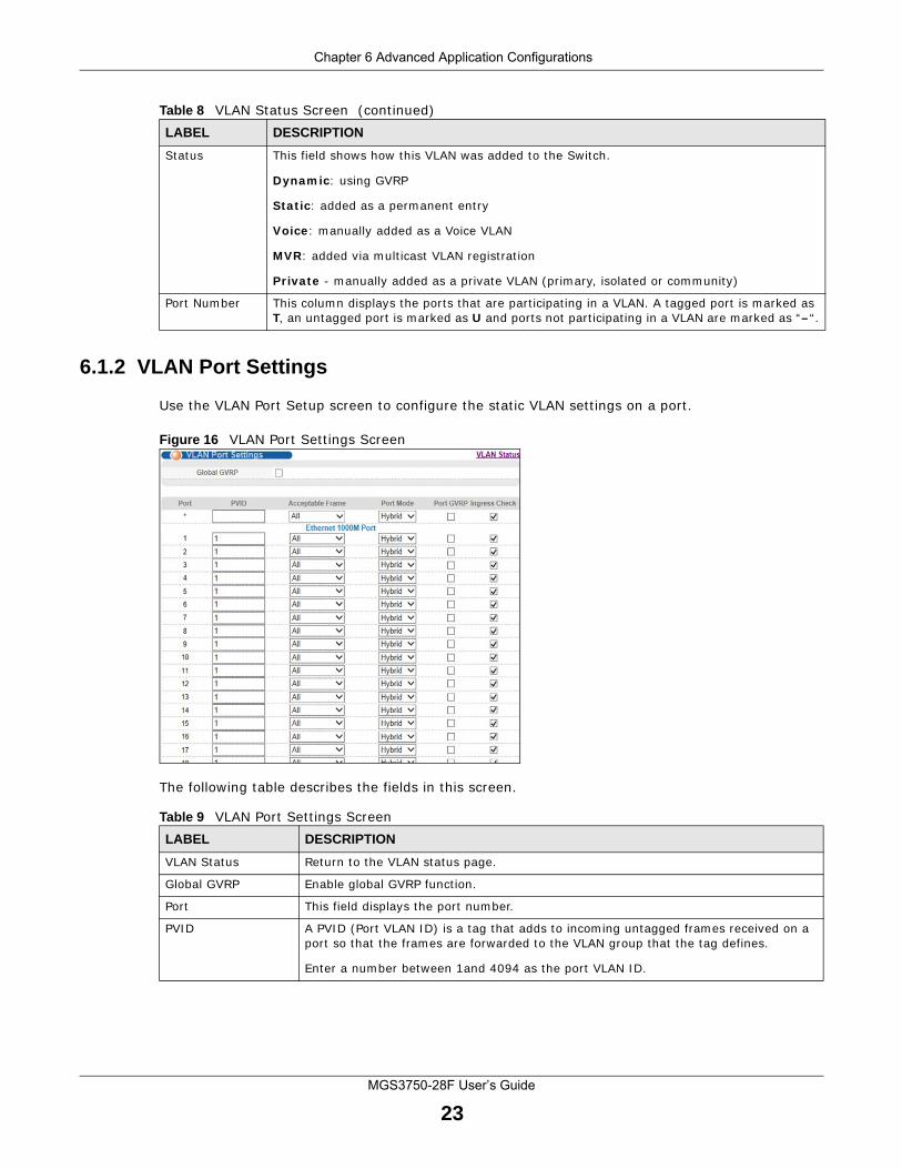
6.1.2 VLAN Port Settings
Use the VLAN Port Setup screen to configure the static VLAN settings on a port.
Figure 16 VLAN Port Settings Screen
The following table describes the fields in this screen.
Status This field shows how this VLAN was added to the Switch.
Dynamic: using GVRP
Static: added as a permanent entry
Voice: manually added as a Voice VLAN
MVR: added via multicast VLAN registration
Private - manually added as a private VLAN (primary, isolated or community)
Port Number This column displays the ports that are participating in a VLAN. A tagged port is marked as T, an untagged port is marked as U and ports not participating in a VLAN are marked as “–“.
Table 8 VLAN Status Screen (continued)LABEL DESCRIPTION
Table 9 VLAN Port Settings ScreenLABEL DESCRIPTION
VLAN Status Return to the VLAN status page.
Global GVRP Enable global GVRP function.
Port This field displays the port number.
PVID A PVID (Port VLAN ID) is a tag that adds to incoming untagged frames received on a port so that the frames are forwarded to the VLAN group that the tag defines.
Enter a number between 1and 4094 as the port VLAN ID.
Chapter 6 Advanced Application Configurations
MGS3750-28F User’s Guide
24
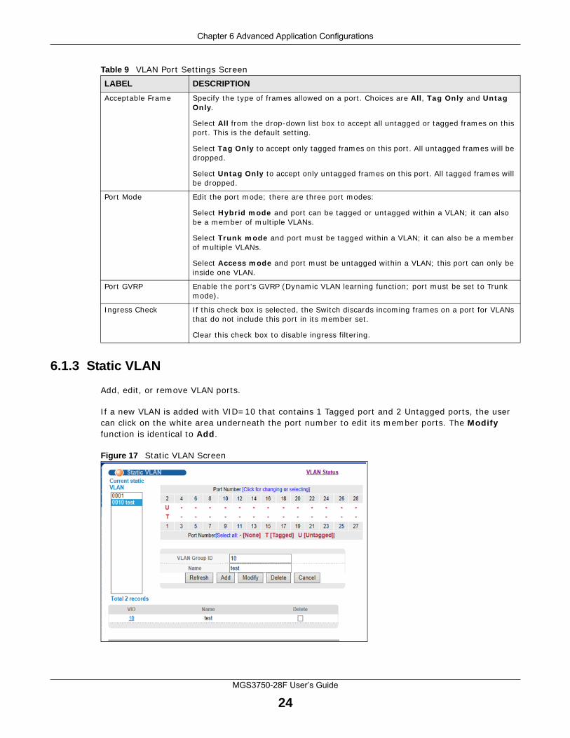
6.1.3 Static VLAN
Add, edit, or remove VLAN ports.
If a new VLAN is added with VID=10 that contains 1 Tagged port and 2 Untagged ports, the user can click on the white area underneath the port number to edit its member ports. The Modify function is identical to Add.
Figure 17 Static VLAN Screen
Acceptable Frame Specify the type of frames allowed on a port. Choices are All, Tag Only and Untag Only.
Select All from the drop-down list box to accept all untagged or tagged frames on this port. This is the default setting.
Select Tag Only to accept only tagged frames on this port. All untagged frames will be dropped.
Select Untag Only to accept only untagged frames on this port. All tagged frames will be dropped.
Port Mode Edit the port mode; there are three port modes:
Select Hybrid mode and port can be tagged or untagged within a VLAN; it can also be a member of multiple VLANs.
Select Trunk mode and port must be tagged within a VLAN; it can also be a member of multiple VLANs.
Select Access mode and port must be untagged within a VLAN; this port can only be inside one VLAN.
Port GVRP Enable the port's GVRP (Dynamic VLAN learning function; port must be set to Trunk mode).
Ingress Check If this check box is selected, the Switch discards incoming frames on a port for VLANs that do not include this port in its member set.
Clear this check box to disable ingress filtering.
Table 9 VLAN Port Settings ScreenLABEL DESCRIPTION
Chapter 6 Advanced Application Configurations
MGS3750-28F User’s Guide
25
The following table describes the labels in this screen.
6.2 Static Mac Forwarding
Manually add dynamic, static, blackhole, and permanent MAC addresses.
A static MAC address is an address that has been manually entered in the MAC address table. Static MAC addresses do not age out. When you set up static MAC address rules, you are setting static MAC addresses for a port. This may reduce the need for broadcasting.
Static MAC address forwarding together with port security allow only computers in the MAC address table on a port to access the Switch.
A blackhole port drops traffic without notifying the sources.
Table 10 Static VLAN ScreenLABEL DESCRIPTION
Current static VLAN
Select the static VLAN group, and make configurations to the group.
Port Number This column displays the ports that are participating in a VLAN. A tagged port is marked as T, an untagged port is marked as U and ports not participating in a VLAN are marked as “–“.
VLAN Group ID Enter the VLAN ID for this static entry; the valid range is between 1 and 4094.
Name Enter a descriptive name for the VLAN group for identification purposes. This name consists of up to 64 printable characters. Spaces are allowed.
Refresh Click Refresh to update the screen.
Add Click Add to save your changes to the Switch’s run-time memory. The Switch loses these changes if it is turned off or loses power.
Modify Select a static VLAN group from Current static VLAN field, and make configurations to the group.
Delete Click Delete to remove the VLAN group ID.
Cancel Click Cancel to change the fields back to their last saved values.
VID This field displays the ID number of the VLAN group. Click the number to edit the VLAN settings.
Name This field diesplays the name of the VID.
Delete Select the check box to delete the VID.
Chapter 6 Advanced Application Configurations
MGS3750-28F User’s Guide
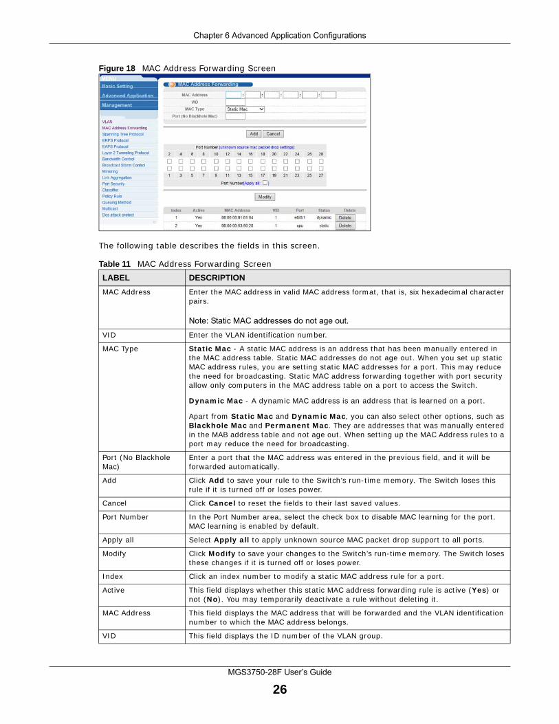
26
Figure 18 MAC Address Forwarding Screen
The following table describes the fields in this screen.
Table 11 MAC Address Forwarding ScreenLABEL DESCRIPTION
MAC Address Enter the MAC address in valid MAC address format, that is, six hexadecimal character pairs.
Note: Static MAC addresses do not age out.
VID Enter the VLAN identification number.
MAC Type Static Mac - A static MAC address is an address that has been manually entered in the MAC address table. Static MAC addresses do not age out. When you set up static MAC address rules, you are setting static MAC addresses for a port. This may reduce the need for broadcasting. Static MAC address forwarding together with port security allow only computers in the MAC address table on a port to access the Switch.
Dynamic Mac - A dynamic MAC address is an address that is learned on a port.
Apart from Static Mac and Dynamic Mac, you can also select other options, such as Blackhole Mac and Permanent Mac. They are addresses that was manually entered in the MAB address table and not age out. When setting up the MAC Address rules to a port may reduce the need for broadcasting.
Port (No Blackhole Mac)
Enter a port that the MAC address was entered in the previous field, and it will be forwarded automatically.
Add Click Add to save your rule to the Switch’s run-time memory. The Switch loses this rule if it is turned off or loses power.
Cancel Click Cancel to reset the fields to their last saved values.
Port Number In the Port Number area, select the check box to disable MAC learning for the port. MAC learning is enabled by default.
Apply all Select Apply all to apply unknown source MAC packet drop support to all ports.
Modify Click Modify to save your changes to the Switch’s run-time memory. The Switch loses these changes if it is turned off or loses power.
Index Click an index number to modify a static MAC address rule for a port.
Active This field displays whether this static MAC address forwarding rule is active (Yes) or not (No). You may temporarily deactivate a rule without deleting it.
MAC Address This field displays the MAC address that will be forwarded and the VLAN identification number to which the MAC address belongs.
VID This field displays the ID number of the VLAN group.
Chapter 6 Advanced Application Configurations
MGS3750-28F User’s Guide
27
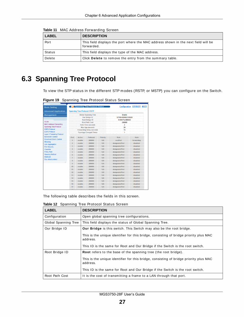
6.3 Spanning Tree Protocol
To view the STP status in the different STP modes (RSTP, or MSTP) you can configure on the Switch.
Figure 19 Spanning Tree Protocol Status Screen
The following table describes the fields in this screen.
Port This field displays the port where the MAC address shown in the next field will be forwarded.
Status This field displays the type of the MAC address.
Delete Click Delete to remove the entry from the summary table.
Table 11 MAC Address Forwarding ScreenLABEL DESCRIPTION
Table 12 Spanning Tree Protocol Status ScreenLABEL DESCRIPTION
Configuration Open global spanning tree configurations.
Global Spanning Tree This field displays the status of Global Spanning Tree.
Our Bridge ID Our Bridge is this switch. This Switch may also be the root bridge.
This is the unique identifier for this bridge, consisting of bridge priority plus MAC address.
This ID is the same for Root and Our Bridge if the Switch is the root switch.
Root Bridge ID Root refers to the base of the spanning tree (the root bridge).
This is the unique identifier for this bridge, consisting of bridge priority plus MAC address.
This ID is the same for Root and Our Bridge if the Switch is the root switch.
Root Path Cost It is the cost of transmitting a frame to a LAN through that port.
Chapter 6 Advanced Application Configurations
MGS3750-28F User’s Guide
28
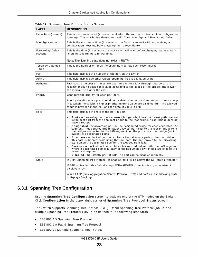
6.3.1 Spanning Tree Configuration
Use the Spanning Tree Configuration screen to activate one of the STP modes on the Switch. Click Configuration in the upper right corner of Spanning Tree Protocol Status screen.
The Switch supports Spanning Tree Protocol (STP), Rapid Spanning Tree Protocol (RSTP) and Multiple Spanning Tree Protocol (MSTP) as defined in the following standards.
• IEEE 802.1D Spanning Tree Protocol
• IEEE 802.1w Rapid Spanning Tree Protocol
• IEEE 802.1s Multiple Spanning Tree Protocol
Hello Time (second) This is the time interval (in seconds) at which the root switch transmits a configuration message. The root bridge determines Hello Time, Max Age and Forwarding Delay.
Max Age (second) This is the maximum time (in seconds) the Switch can wait without receiving a configuration message before attempting to reconfigure.
Forwarding Delay (second)
This is the time (in seconds) the root switch will wait before changing states (that is, listening to learning to forwarding).
Note: The listening state does not exist in RSTP.
Topology Changed Times
This is the number of times the spanning tree has been reconfigured.
Port This field displays the number of the port on the Switch.
Active This field displays whether Global Spanning Tree is activated or not.
Pathcost Path cost is the cost of transmitting a frame on to a LAN through that port. It is recommended to assign this value according to the speed of the bridge. The slower the media, the higher the cost.
Priority Configure the priority for each port here.
Priority decides which port should be disabled when more than one port forms a loop in a switch. Ports with a higher priority numeric value are disabled first. The allowed range is between 0 and 255 and the default value is 128.
Role This field displays the role of the port in STP.
• Root - A forwarding port on a non-root bridge, which has the lowest path cost and is the best port from the non-root bridge to the root bridge. A root bridge does not have a root port.
• Designated - A forwarding port on the designated bridge for each connected LAN segment. A designated bridge has the lowest path cost to the root bridge among the bridges connected to the LAN segment. All the ports on a root bridge (root switch) are designated ports.
• Alternate - A blocked port, which has a best alternate path to the root bridge. This path is different from using the root port. The port moves to the forwarding state when the designated port for the LAN segment fails.
• Backup - A blocked port, which has a backup/redundant path to a LAN segment where a designated port is already connected when a switch has two links to the same LAN segment.
• Disabled - Not strictly part of STP. The port can be disabled manually.
State If STP (Spanning Tree Protocol) is enabled, this field displays the STP state of the port.
If STP is disabled, this field displays FORWARDING if the link is up, otherwise, it displays STOP.
When LACP (Link Aggregation Control Protocol), STP, and dot1x are in blocking state, it displays Blocking.
Table 12 Spanning Tree Protocol Status ScreenLABEL DESCRIPTION
Chapter 6 Advanced Application Configurations
MGS3750-28F User’s Guide
29
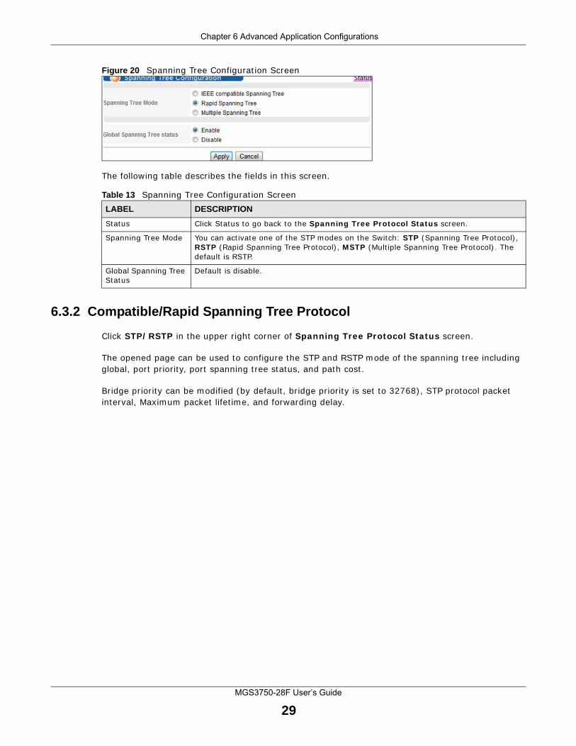
Figure 20 Spanning Tree Configuration Screen
The following table describes the fields in this screen.
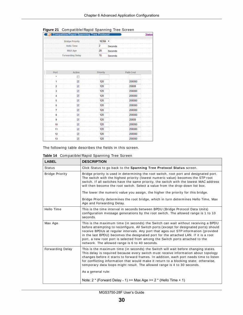
6.3.2 Compatible/Rapid Spanning Tree Protocol
Click STP/RSTP in the upper right corner of Spanning Tree Protocol Status screen.
The opened page can be used to configure the STP and RSTP mode of the spanning tree including global, port priority, port spanning tree status, and path cost.
Bridge priority can be modified (by default, bridge priority is set to 32768), STP protocol packet interval, Maximum packet lifetime, and forwarding delay.
Table 13 Spanning Tree Configuration ScreenLABEL DESCRIPTION
Status Click Status to go back to the Spanning Tree Protocol Status screen.
Spanning Tree Mode You can activate one of the STP modes on the Switch: STP (Spanning Tree Protocol), RSTP (Rapid Spanning Tree Protocol), MSTP (Multiple Spanning Tree Protocol). The default is RSTP.
Global Spanning Tree Status
Default is disable.
Chapter 6 Advanced Application Configurations
MGS3750-28F User’s Guide
30
Figure 21 Compatible/Rapid Spanning Tree Screen
The following table describes the fields in this screen.
Table 14 Compatible/Rapid Spanning Tree ScreenLABEL DESCRIPTION
Status Click Status to go back to the Spanning Tree Protocol Status screen.
Bridge Priority Bridge priority is used in determining the root switch, root port and designated port. The switch with the highest priority (lowest numeric value) becomes the STP root switch. If all switches have the same priority, the switch with the lowest MAC address will then become the root switch. Select a value from the drop-down list box.
The lower the numeric value you assign, the higher the priority for this bridge.
Bridge Priority determines the root bridge, which in turn determines Hello Time, Max Age and Forwarding Delay.
Hello Time This is the time interval in seconds between BPDU (Bridge Protocol Data Units) configuration message generations by the root switch. The allowed range is 1 to 10 seconds.
Max Age This is the maximum time (in seconds) the Switch can wait without receiving a BPDU before attempting to reconfigure. All Switch ports (except for designated ports) should receive BPDUs at regular intervals. Any port that ages out STP information (provided in the last BPDU) becomes the designated port for the attached LAN. If it is a root port, a new root port is selected from among the Switch ports attached to the network. The allowed range is 6 to 40 seconds.
Forwarding Delay This is the maximum time (in seconds) the Switch will wait before changing states. This delay is required because every switch must receive information about topology changes before it starts to forward frames. In addition, each port needs time to listen for conflicting information that would make it return to a blocking state; otherwise, temporary data loops might result. The allowed range is 4 to 30 seconds.
As a general rule:
Note: 2 * (Forward Delay - 1) >= Max Age >= 2 * (Hello Time + 1)
Chapter 6 Advanced Application Configurations
MGS3750-28F User’s Guide
31
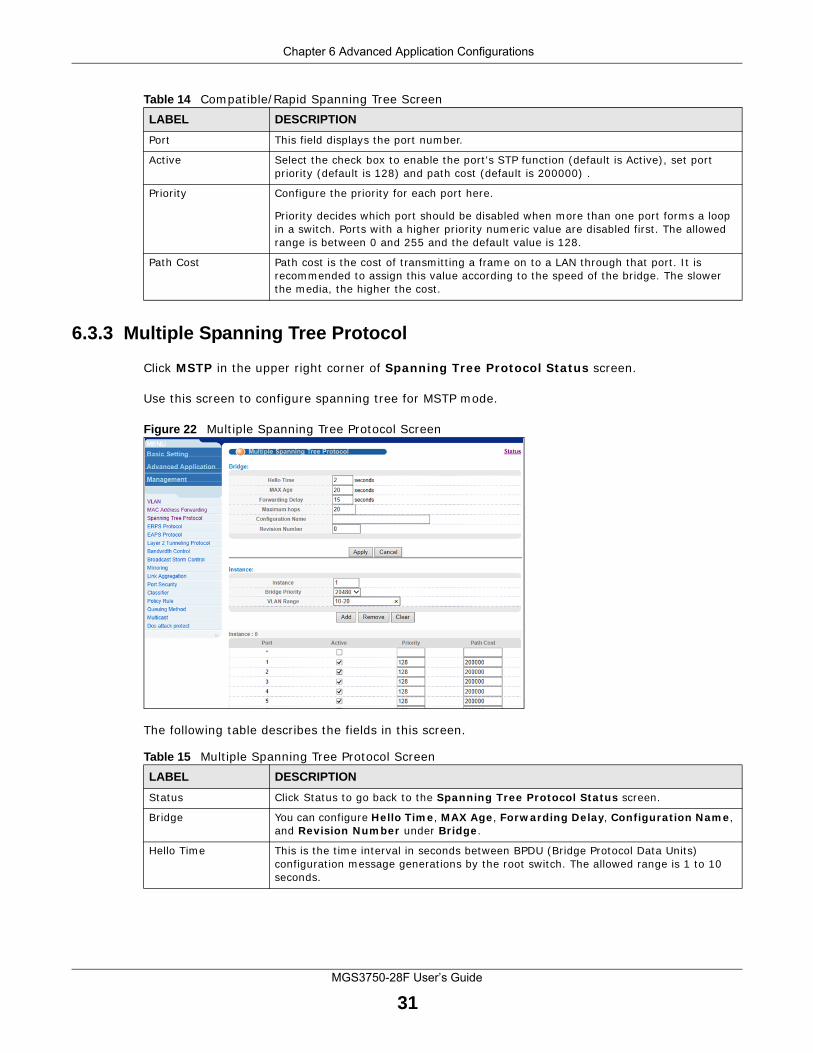
6.3.3 Multiple Spanning Tree Protocol
Click MSTP in the upper right corner of Spanning Tree Protocol Status screen.
Use this screen to configure spanning tree for MSTP mode.
Figure 22 Multiple Spanning Tree Protocol Screen
The following table describes the fields in this screen.
Port This field displays the port number.
Active Select the check box to enable the port's STP function (default is Active), set port priority (default is 128) and path cost (default is 200000) .
Priority Configure the priority for each port here.
Priority decides which port should be disabled when more than one port forms a loop in a switch. Ports with a higher priority numeric value are disabled first. The allowed range is between 0 and 255 and the default value is 128.
Path Cost Path cost is the cost of transmitting a frame on to a LAN through that port. It is recommended to assign this value according to the speed of the bridge. The slower the media, the higher the cost.
Table 14 Compatible/Rapid Spanning Tree ScreenLABEL DESCRIPTION
Table 15 Multiple Spanning Tree Protocol ScreenLABEL DESCRIPTION
Status Click Status to go back to the Spanning Tree Protocol Status screen.
Bridge You can configure Hello Time, MAX Age, Forwarding Delay, Configuration Name, and Revision Number under Bridge.
Hello Time This is the time interval in seconds between BPDU (Bridge Protocol Data Units) configuration message generations by the root switch. The allowed range is 1 to 10 seconds.
Chapter 6 Advanced Application Configurations
MGS3750-28F User’s Guide
32
Max Age This is the maximum time (in seconds) the Switch can wait without receiving a BPDU before attempting to reconfigure. All Switch ports (except for designated ports) should receive BPDUs at regular intervals. Any port that ages out STP information (provided in the last BPDU) becomes the designated port for the attached LAN. If it is a root port, a new root port is selected from among the Switch ports attached to the network. The allowed range is 6 to 40 seconds.
Forwarding Delay This is the maximum time (in seconds) the Switch will wait before changing states. This delay is required because every switch must receive information about topology changes before it starts to forward frames. In addition, each port needs time to listen for conflicting information that would make it return to a blocking state; otherwise, temporary data loops might result. The allowed range is 4 to 30 seconds. As a general rule:
Note: 2 * (Forward Delay - 1) >= Max Age >= 2 * (Hello Time + 1)
Maximum hops Enter the number of hops (between 1 and 255) in an MSTP region before the BPDU is discarded and the port information is aged.
Configuration Name Enter a descriptive name (up to 32 characters) of an MST region.
Revision Number Enter a number to identify a region’s configuration. Devices must have the same revision number to belong to the same region.
Apply Click Apply to save your changes to the Switch’s run-time memory. The Switch loses these changes if it is turned off or loses power.
Cancel Click Cancel to begin configuring this screen afresh.
Instance Instances can be added or removed from the table. For example, if instance 1 is added with instance priority 20480 (default is 32768) , then it mirrors VLAN 10 - 20. The port status for MSTP spanning tree can be configured; configuration is identical to the RSTP port.
Instance Enter the number you want to use to identify this MST instance on the Switch. The Switch supports instance numbers 0-15.
Bridge Priority Set the priority of the Switch for the specific spanning tree instance. The lower the number, the more likely the Switch will be chosen as the root bridge within the spanning tree instance.
Enter priority values between 0 and 61440 in increments of 4096 (thus valid values are 4096, 8192, 12288, 16384, 20480, 24576, 28672, 32768, 36864, 40960, 45056, 49152, 53248, 57344 and 61440).
VLAN Range Enter the start of the VLAN ID range that you want to add or remove from the VLAN range edit area in the Start field. Enter the end of the VLAN ID range that you want to add or remove from the VLAN range edit area in the End field.
Next click:
• Add - to add this range of VLAN(s) to be mapped to the MST instance. • Remove - to remove this range of VLAN(s) from being mapped to the MST
instance. • Clear - to remove all VLAN(s) from being mapped to this MST instance.
Port This field displays the port number.
* Settings in this row apply to all ports.
Use this row only if you want to make some settings the same for all ports. Use this row first to set the common settings and then make adjustments on a port-by-port basis.
Note: Changes in this row are copied to all the ports as soon as you make them.
Active Select this check box to add this port to the MST instance.
Table 15 Multiple Spanning Tree Protocol ScreenLABEL DESCRIPTION
Chapter 6 Advanced Application Configurations
MGS3750-28F User’s Guide
33
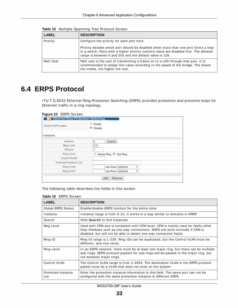
6.4 ERPS Protocol
ITU-T G.8032 Ethernet Ring Protection Switching (ERPS) provides protection and prevents loops for Ethernet traffic in a ring topology.
Figure 23 ERPS Screen
The following table describes the fields in this screen.
Priority Configure the priority for each port here.
Priority decides which port should be disabled when more than one port forms a loop in a switch. Ports with a higher priority numeric value are disabled first. The allowed range is between 0 and 255 and the default value is 128.
Path Cost Path cost is the cost of transmitting a frame on to a LAN through that port. It is recommended to assign this value according to the speed of the bridge. The slower the media, the higher the cost.
Table 15 Multiple Spanning Tree Protocol ScreenLABEL DESCRIPTION
Table 16 ERPS ScreenLABEL DESCRIPTION
Global ERPS Status Enable/disable ERPS function for the entire zone.
Instance Instance range is from 0-15; it works in a way similar to domains in ERRP.
Search Click Search to find instances.
Meg Level Used with CFM and is consistent with CFM level. CFM is mainly used for faults other than linkdown such as one-way connections; ERPS will work normally if CFM is disabled, but will not be able to detect one-way connection faults.
Ring ID Ring ID range is 1-239. Ring IDs can be duplicated, but the Control VLAN must be different, and vice versa.
Ring Level In an ERPS network, there must be at least one major ring, but there can be multiple sub-rings. ERPS protocol packets for sub-rings will be passed to the major ring, but not between major rings.
Control VLAN The Control VLAN range is from 2-4094. The destination VLAN in the ERPS protocol packet must be a VLAN that does not exist on the system.
Protected-instance List
Enter the protection instance information in this field. The same port can not be configured with the same protection instance in different ERPS.
Chapter 6 Advanced Application Configurations
MGS3750-28F User’s Guide
34
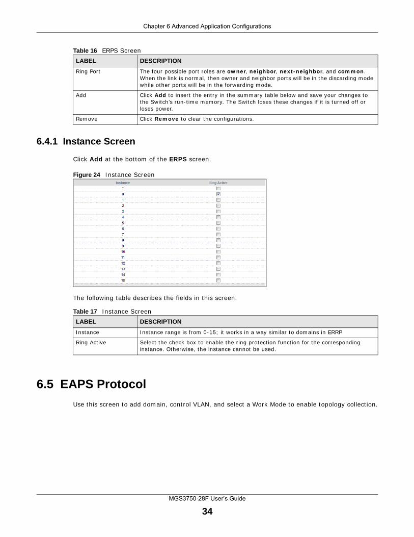
6.4.1 Instance Screen
Click Add at the bottom of the ERPS screen.
Figure 24 Instance Screen
The following table describes the fields in this screen.
6.5 EAPS Protocol
Use this screen to add domain, control VLAN, and select a Work Mode to enable topology collection.
Ring Port The four possible port roles are owner, neighbor, next-neighbor, and common. When the link is normal, then owner and neighbor ports will be in the discarding mode while other ports will be in the forwarding mode.
Add Click Add to insert the entry in the summary table below and save your changes to the Switch’s run-time memory. The Switch loses these changes if it is turned off or loses power.
Remove Click Remove to clear the configurations.
Table 16 ERPS ScreenLABEL DESCRIPTION
Table 17 Instance ScreenLABEL DESCRIPTION
Instance Instance range is from 0-15; it works in a way similar to domains in ERRP.
Ring Active Select the check box to enable the ring protection function for the corresponding instance. Otherwise, the instance cannot be used.
Chapter 6 Advanced Application Configurations
MGS3750-28F User’s Guide
35
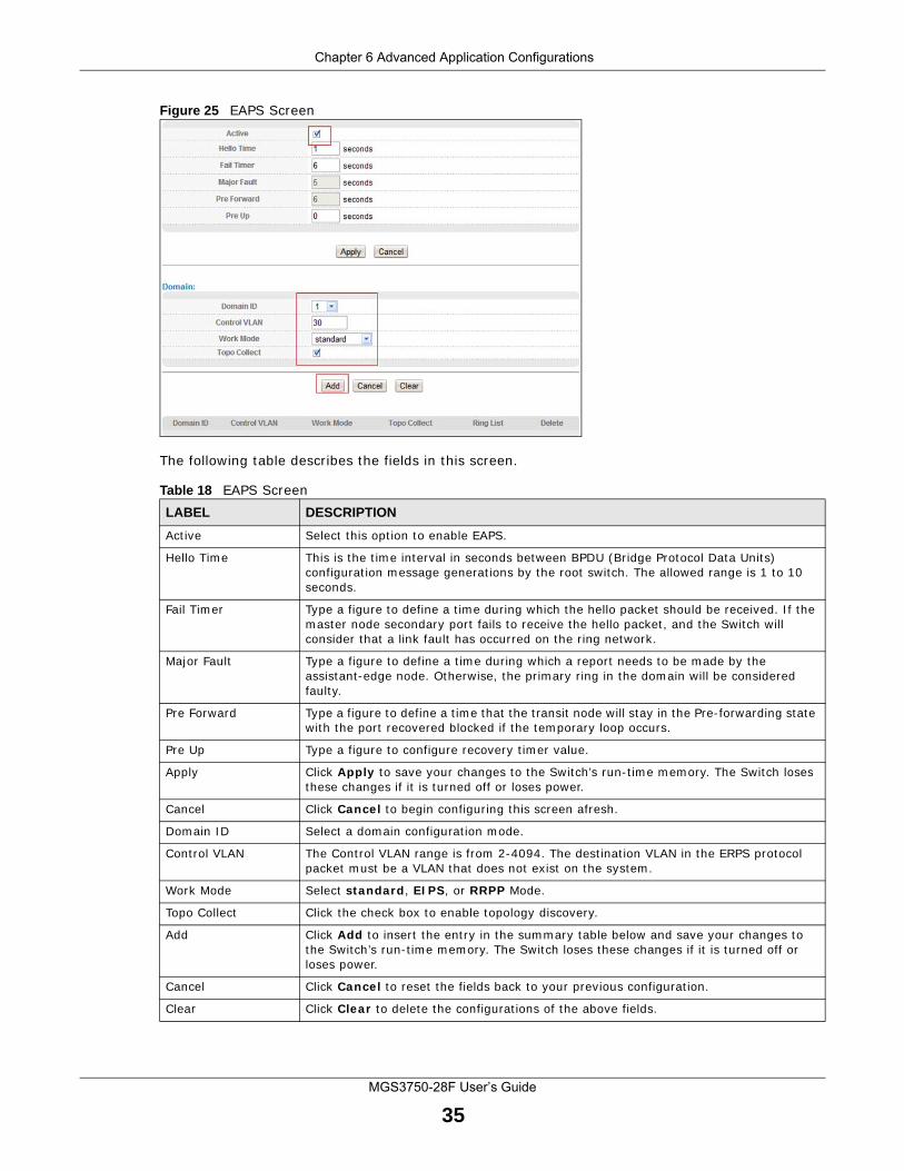
Figure 25 EAPS Screen
The following table describes the fields in this screen.
Table 18 EAPS ScreenLABEL DESCRIPTION
Active Select this option to enable EAPS.
Hello Time This is the time interval in seconds between BPDU (Bridge Protocol Data Units) configuration message generations by the root switch. The allowed range is 1 to 10 seconds.
Fail Timer Type a figure to define a time during which the hello packet should be received. If the master node secondary port fails to receive the hello packet, and the Switch will consider that a link fault has occurred on the ring network.
Major Fault Type a figure to define a time during which a report needs to be made by the assistant-edge node. Otherwise, the primary ring in the domain will be considered faulty.
Pre Forward Type a figure to define a time that the transit node will stay in the Pre-forwarding state with the port recovered blocked if the temporary loop occurs.
Pre Up Type a figure to configure recovery timer value.
Apply Click Apply to save your changes to the Switch’s run-time memory. The Switch loses these changes if it is turned off or loses power.
Cancel Click Cancel to begin configuring this screen afresh.
Domain ID Select a domain configuration mode.
Control VLAN The Control VLAN range is from 2-4094. The destination VLAN in the ERPS protocol packet must be a VLAN that does not exist on the system.
Work Mode Select standard, EIPS, or RRPP Mode.
Topo Collect Click the check box to enable topology discovery.
Add Click Add to insert the entry in the summary table below and save your changes to the Switch’s run-time memory. The Switch loses these changes if it is turned off or loses power.
Cancel Click Cancel to reset the fields back to your previous configuration.
Clear Click Clear to delete the configurations of the above fields.
Chapter 6 Advanced Application Configurations
MGS3750-28F User’s Guide
36
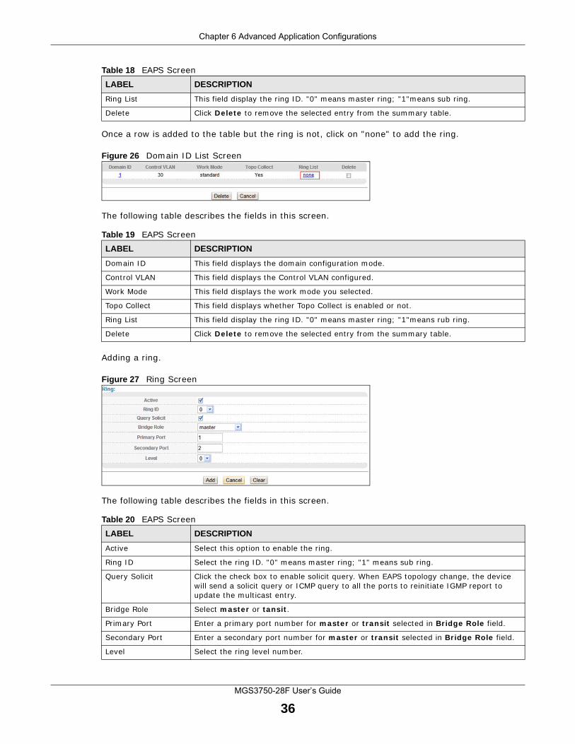
Once a row is added to the table but the ring is not, click on "none" to add the ring.
Figure 26 Domain ID List Screen
The following table describes the fields in this screen.
Adding a ring.
Figure 27 Ring Screen
The following table describes the fields in this screen.
Ring List This field display the ring ID. "0" means master ring; "1"means sub ring.
Delete Click Delete to remove the selected entry from the summary table.
Table 19 EAPS ScreenLABEL DESCRIPTION
Domain ID This field displays the domain configuration mode.
Control VLAN This field displays the Control VLAN configured.
Work Mode This field displays the work mode you selected.
Topo Collect This field displays whether Topo Collect is enabled or not.
Ring List This field display the ring ID. "0" means master ring; "1"means rub ring.
Delete Click Delete to remove the selected entry from the summary table.
Table 20 EAPS ScreenLABEL DESCRIPTION
Active Select this option to enable the ring.
Ring ID Select the ring ID. "0" means master ring; "1" means sub ring.
Query Solicit Click the check box to enable solicit query. When EAPS topology change, the device will send a solicit query or ICMP query to all the ports to reinitiate IGMP report to update the multicast entry.
Bridge Role Select master or tansit.
Primary Port Enter a primary port number for master or transit selected in Bridge Role field.
Secondary Port Enter a secondary port number for master or transit selected in Bridge Role field.
Level Select the ring level number.
Table 18 EAPS ScreenLABEL DESCRIPTION
Chapter 6 Advanced Application Configurations
MGS3750-28F User’s Guide
37
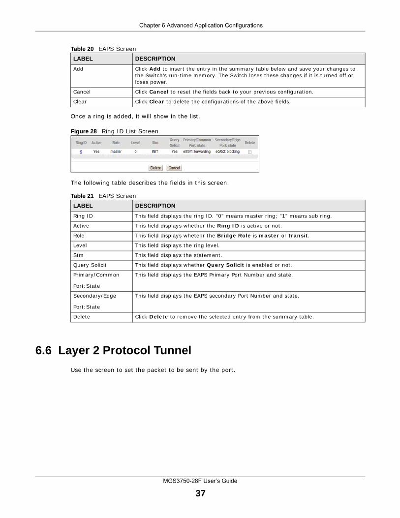
Once a ring is added, it will show in the list.
Figure 28 Ring ID List Screen
The following table describes the fields in this screen.
6.6 Layer 2 Protocol Tunnel
Use the screen to set the packet to be sent by the port.
Add Click Add to insert the entry in the summary table below and save your changes to the Switch’s run-time memory. The Switch loses these changes if it is turned off or loses power.
Cancel Click Cancel to reset the fields back to your previous configuration.
Clear Click Clear to delete the configurations of the above fields.
Table 21 EAPS ScreenLABEL DESCRIPTION
Ring ID This field displays the ring ID. "0" means master ring; "1" means sub ring.
Active This field displays whether the Ring ID is active or not.
Role This field displays whetehr the Bridge Role is master or transit.
Level This field displays the ring level.
Stm This field displays the statement.
Query Solicit This field displays whether Query Solicit is enabled or not.
Primary/Common
Port:State
This field displays the EAPS Primary Port Number and state.
Secondary/Edge
Port:State
This field displays the EAPS secondary Port Number and state.
Delete Click Delete to remove the selected entry from the summary table.
Table 20 EAPS ScreenLABEL DESCRIPTION
Chapter 6 Advanced Application Configurations
MGS3750-28F User’s Guide
38
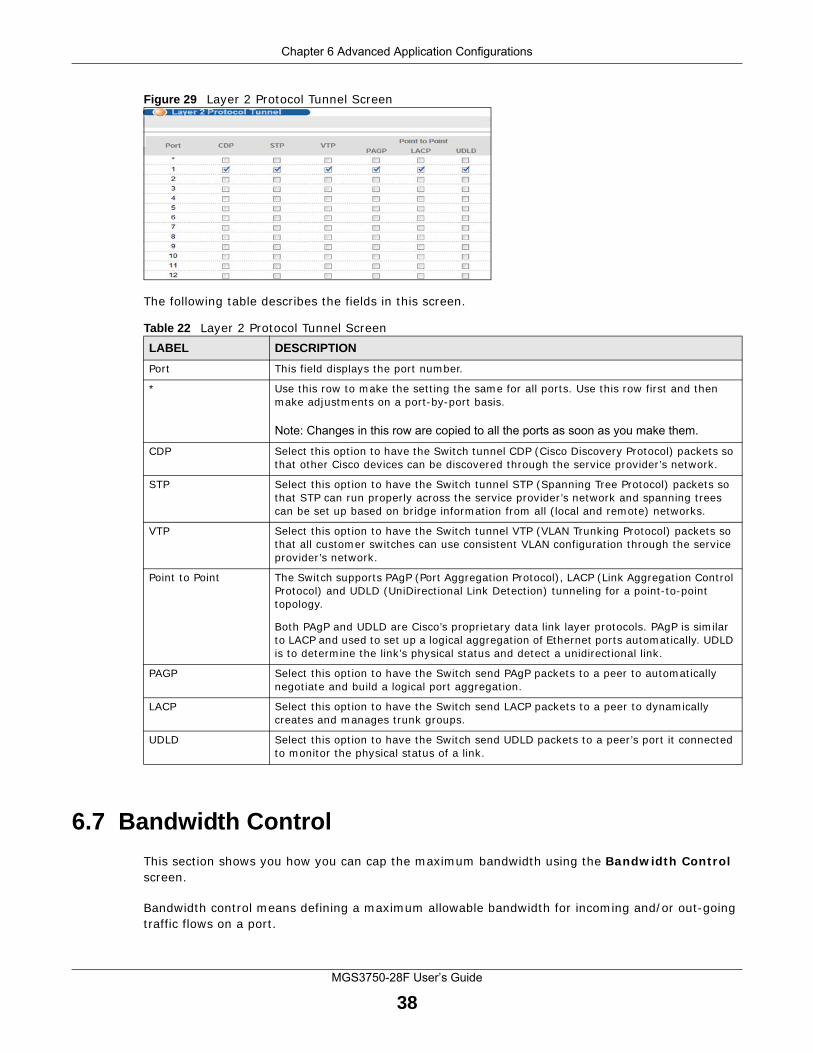
Figure 29 Layer 2 Protocol Tunnel Screen
The following table describes the fields in this screen.
6.7 Bandwidth Control
This section shows you how you can cap the maximum bandwidth using the Bandwidth Control screen.
Bandwidth control means defining a maximum allowable bandwidth for incoming and/or out-going traffic flows on a port.
Table 22 Layer 2 Protocol Tunnel ScreenLABEL DESCRIPTION
Port This field displays the port number.
* Use this row to make the setting the same for all ports. Use this row first and then make adjustments on a port-by-port basis.
Note: Changes in this row are copied to all the ports as soon as you make them.
CDP Select this option to have the Switch tunnel CDP (Cisco Discovery Protocol) packets so that other Cisco devices can be discovered through the service provider’s network.
STP Select this option to have the Switch tunnel STP (Spanning Tree Protocol) packets so that STP can run properly across the service provider’s network and spanning trees can be set up based on bridge information from all (local and remote) networks.
VTP Select this option to have the Switch tunnel VTP (VLAN Trunking Protocol) packets so that all customer switches can use consistent VLAN configuration through the service provider’s network.
Point to Point The Switch supports PAgP (Port Aggregation Protocol), LACP (Link Aggregation Control Protocol) and UDLD (UniDirectional Link Detection) tunneling for a point-to-point topology.
Both PAgP and UDLD are Cisco’s proprietary data link layer protocols. PAgP is similar to LACP and used to set up a logical aggregation of Ethernet ports automatically. UDLD is to determine the link’s physical status and detect a unidirectional link.
PAGP Select this option to have the Switch send PAgP packets to a peer to automatically negotiate and build a logical port aggregation.
LACP Select this option to have the Switch send LACP packets to a peer to dynamically creates and manages trunk groups.
UDLD Select this option to have the Switch send UDLD packets to a peer’s port it connected to monitor the physical status of a link.
Chapter 6 Advanced Application Configurations
MGS3750-28F User’s Guide
39
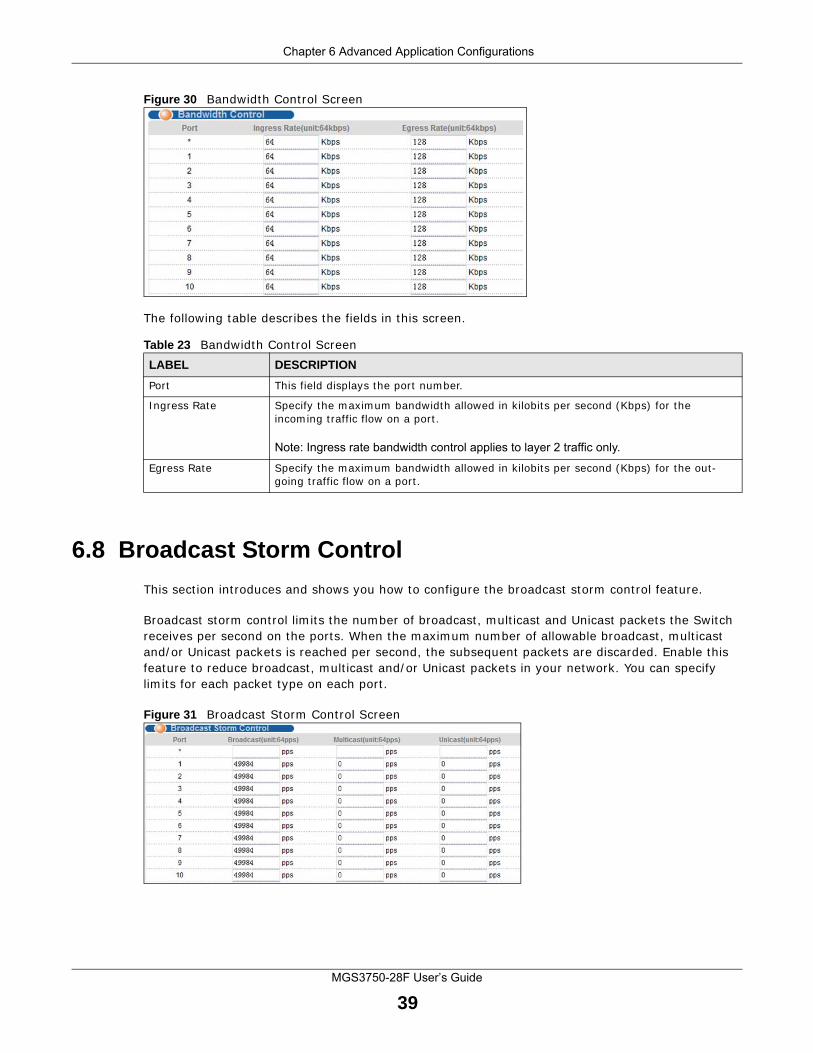
Figure 30 Bandwidth Control Screen
The following table describes the fields in this screen.
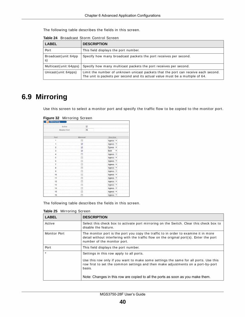
6.8 Broadcast Storm Control
This section introduces and shows you how to configure the broadcast storm control feature.
Broadcast storm control limits the number of broadcast, multicast and Unicast packets the Switch receives per second on the ports. When the maximum number of allowable broadcast, multicast and/or Unicast packets is reached per second, the subsequent packets are discarded. Enable this feature to reduce broadcast, multicast and/or Unicast packets in your network. You can specify limits for each packet type on each port.
Figure 31 Broadcast Storm Control Screen
Table 23 Bandwidth Control ScreenLABEL DESCRIPTION
Port This field displays the port number.
Ingress Rate Specify the maximum bandwidth allowed in kilobits per second (Kbps) for the incoming traffic flow on a port.
Note: Ingress rate bandwidth control applies to layer 2 traffic only.
Egress Rate Specify the maximum bandwidth allowed in kilobits per second (Kbps) for the out-going traffic flow on a port.
Chapter 6 Advanced Application Configurations
MGS3750-28F User’s Guide
40
The following table describes the fields in this screen.
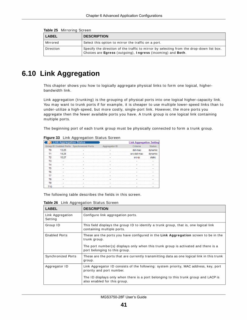
6.9 Mirroring
Use this screen to select a monitor port and specify the traffic flow to be copied to the monitor port.
Figure 32 Mirroring Screen
The following table describes the fields in this screen.
Table 24 Broadcast Storm Control ScreenLABEL DESCRIPTION
Port This field displays the port number.
Broadcast(unit:64pps)
Specify how many broadcast packets the port receives per second.
Multicast(unit:64pps) Specify how many multicast packets the port receives per second.
Unicast(unit:64pps) Limit the number of unknown unicast packets that the port can receive each second. The unit is packets per second and its actual value must be a multiple of 64.
Table 25 Mirroring ScreenLABEL DESCRIPTION
Active Select this check box to activate port mirroring on the Switch. Clear this check box to disable the feature.
Monitor Port The monitor port is the port you copy the traffic to in order to examine it in more detail without interfering with the traffic flow on the original port(s). Enter the port number of the monitor port.
Port This field displays the port number.
* Settings in this row apply to all ports.
Use this row only if you want to make some settings the same for all ports. Use this row first to set the common settings and then make adjustments on a port-by-port basis.
Note: Changes in this row are copied to all the ports as soon as you make them.
Chapter 6 Advanced Application Configurations
MGS3750-28F User’s Guide
41
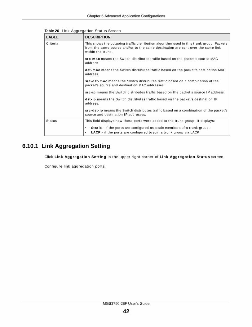
6.10 Link Aggregation
This chapter shows you how to logically aggregate physical links to form one logical, higher-bandwidth link.
Link aggregation (trunking) is the grouping of physical ports into one logical higher-capacity link. You may want to trunk ports if for example, it is cheaper to use multiple lower-speed links than to under-utilize a high-speed, but more costly, single-port link. However, the more ports you aggregate then the fewer available ports you have. A trunk group is one logical link containing multiple ports.
The beginning port of each trunk group must be physically connected to form a trunk group.
Figure 33 Link Aggregation Status Screen
The following table describes the fields in this screen.
Mirrored Select this option to mirror the traffic on a port.
Direction Specify the direction of the traffic to mirror by selecting from the drop-down list box. Choices are Egress (outgoing), Ingress (incoming) and Both.
Table 25 Mirroring ScreenLABEL DESCRIPTION
Table 26 Link Aggregation Status ScreenLABEL DESCRIPTION
Link Aggregation Setting
Configure link aggregation ports.
Group ID This field displays the group ID to identify a trunk group, that is, one logical link containing multiple ports.
Enabled Ports These are the ports you have configured in the Link Aggregation screen to be in the trunk group.
The port number(s) displays only when this trunk group is activated and there is a port belonging to this group.
Synchronized Ports These are the ports that are currently transmitting data as one logical link in this trunk group.
Aggregator ID Link Aggregator ID consists of the following: system priority, MAC address, key, port priority and port number.
The ID displays only when there is a port belonging to this trunk group and LACP is also enabled for this group.
Chapter 6 Advanced Application Configurations
MGS3750-28F User’s Guide
42
6.10.1 Link Aggregation Setting
Click Link Aggregation Setting in the upper right corner of Link Aggregation Status screen.
Configure link aggregation ports.
Criteria This shows the outgoing traffic distribution algorithm used in this trunk group. Packets from the same source and/or to the same destination are sent over the same link within the trunk.
src-mac means the Switch distributes traffic based on the packet’s source MAC address.
dst-mac means the Switch distributes traffic based on the packet’s destination MAC address.
src-dst-mac means the Switch distributes traffic based on a combination of the packet’s source and destination MAC addresses.
src-ip means the Switch distributes traffic based on the packet’s source IP address.
dst-ip means the Switch distributes traffic based on the packet’s destination IP address.
src-dst-ip means the Switch distributes traffic based on a combination of the packet’s source and destination IP addresses.
Status This field displays how these ports were added to the trunk group. It displays:
• Static - if the ports are configured as static members of a trunk group.• LACP - if the ports are configured to join a trunk group via LACP.
Table 26 Link Aggregation Status ScreenLABEL DESCRIPTION
Chapter 6 Advanced Application Configurations
MGS3750-28F User’s Guide
43
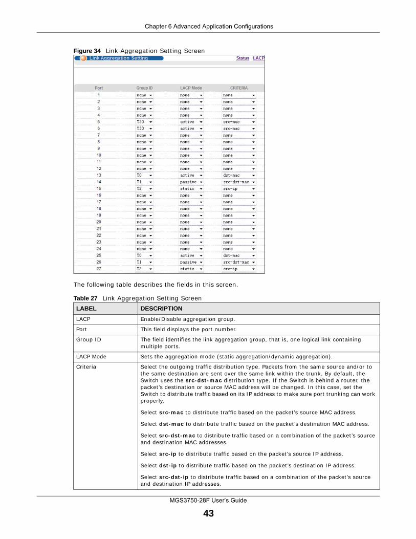
Figure 34 Link Aggregation Setting Screen
The following table describes the fields in this screen.
Table 27 Link Aggregation Setting ScreenLABEL DESCRIPTION
LACP Enable/Disable aggregation group.
Port This field displays the port number.
Group ID The field identifies the link aggregation group, that is, one logical link containing multiple ports.
LACP Mode Sets the aggregation mode (static aggregation/dynamic aggregation).
Criteria Select the outgoing traffic distribution type. Packets from the same source and/or to the same destination are sent over the same link within the trunk. By default, the Switch uses the src-dst-mac distribution type. If the Switch is behind a router, the packet’s destination or source MAC address will be changed. In this case, set the Switch to distribute traffic based on its IP address to make sure port trunking can work properly.
Select src-mac to distribute traffic based on the packet’s source MAC address.
Select dst-mac to distribute traffic based on the packet’s destination MAC address.
Select src-dst-mac to distribute traffic based on a combination of the packet’s source and destination MAC addresses.
Select src-ip to distribute traffic based on the packet’s source IP address.
Select dst-ip to distribute traffic based on the packet’s destination IP address.
Select src-dst-ip to distribute traffic based on a combination of the packet’s source and destination IP addresses.
Chapter 6 Advanced Application Configurations
MGS3750-28F User’s Guide
44
6.10.2 Link Aggregation Control Protocol
Use this screen to enable Link Aggregation Control Protocol.
Click LACP in the upper right corner of Link Aggregation Setting screen.
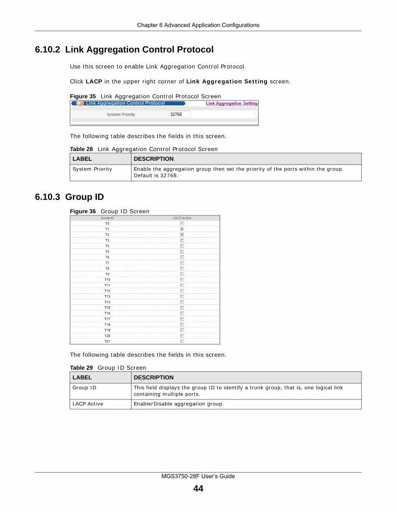
Figure 35 Link Aggregation Control Protocol Screen
The following table describes the fields in this screen.
6.10.3 Group ID
Figure 36 Group ID Screen
The following table describes the fields in this screen.
Table 28 Link Aggregation Control Protocol ScreenLABEL DESCRIPTION
System Priority Enable the aggregation group then set the priority of the ports within the group. Default is 32768.
Table 29 Group ID ScreenLABEL DESCRIPTION
Group ID This field displays the group ID to identify a trunk group, that is, one logical link containing multiple ports.
LACP Active Enable/Disable aggregation group.
Chapter 6 Advanced Application Configurations
MGS3750-28F User’s Guide
45
6.10.4 Port
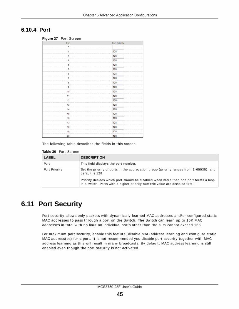
Figure 37 Port Screen
The following table describes the fields in this screen.
6.11 Port Security
Port security allows only packets with dynamically learned MAC addresses and/or configured static MAC addresses to pass through a port on the Switch. The Switch can learn up to 16K MAC addresses in total with no limit on individual ports other than the sum cannot exceed 16K.
For maximum port security, enable this feature, disable MAC address learning and configure static MAC address(es) for a port. It is not recommended you disable port security together with MAC address learning as this will result in many broadcasts. By default, MAC address learning is still enabled even though the port security is not activated.
Table 30 Port ScreenLABEL DESCRIPTION
Port This field displays the port number.
Port Priority Set the priority of ports in the aggregation group (priority ranges from 1-65535), and default is 128.
Priority decides which port should be disabled when more than one port forms a loop in a switch. Ports with a higher priority numeric value are disabled first.
Chapter 6 Advanced Application Configurations
MGS3750-28F User’s Guide
46
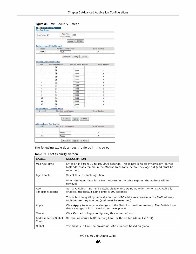
Figure 38 Port Security Screen
The following table describes the fields in this screen.
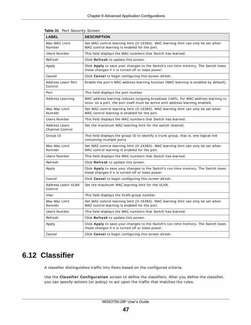
Table 31 Port Security ScreenLABEL DESCRIPTION
Mac Age Time Enter a time from 10 to 1000000 seconds. This is how long all dynamically learned MAC addresses remain in the MAC address table before they age out (and must be relearned).
Age-Enable Select this to enable age time.
When the aging time for a MAC address in the table expires, the address will be removed
Age Time(unit:second)
Set MAC Aging Time, and enable/disable MAC Aging Function. When MAC Aging is enabled, the default aging time is 300 seconds.
This is how long all dynamically learned MAC addresses remain in the MAC address table before they age out (and must be relearned).
Apply Click Apply to save your changes to the Switch’s run-time memory. The Switch loses these changes if it is turned off or loses power.
Cancel Click Cancel to begin configuring this screen afresh..
Address Learn Global Control
Set the maximum MAC learning limit for the switch (default is 16K).
Global This field is to limit the maximum MAC numbers based on global.
Chapter 6 Advanced Application Configurations
MGS3750-28F User’s Guide
47
6.12 Classifier
A classifier distinguishes traffic into flows based on the configured criteria.
Use the Classifier Configuration screen to define the classifiers. After you define the classifier, you can specify actions (or policy) to act upon the traffic that matches the rules.
Max MAC Limit Number
Set MAC control learning limit (0-16384). MAC learning limit can only be set when MAC control learning is enabled for the port.
Users Number This field displays the MAC numbers that Switch has learned.
Refresh Click Refresh to update this screen.
Apply Click Apply to save your changes to the Switch’s run-time memory. The Switch loses these changes if it is turned off or loses power.
Cancel Click Cancel to begin configuring this screen afresh..
Address Learn Port Control
Enable the port's MAC address learning function (MAC learning is enabled by default).
Port This field displays the port number.
Address Learning MAC address learning reduces outgoing broadcast traffic. For MAC address learning to occur on a port, the port itself must be active with address learning enabled.
Max Mac Limit Numebr
Set MAC control learning limit (0-16384). MAC learning limit can only be set when MAC control learning is enabled for the port.
Users Number This field displays the MAC numbers that Switch has learned.
Address Learn Channel Control
Set the maximum MAC learning limit for the switch channel.
Group ID This field displays the group ID to identify a trunk group, that is, one logical link containing multiple ports.
Max Mac Limit Numebr
Set MAC control learning limit (0-16384). MAC learning limit can only be set when MAC control learning is enabled for the port.
Users Number This field displays the MAC numbers that Switch has learned.
Refresh Click Refresh to update this screen.
Apply Click Apply to save your changes to the Switch’s run-time memory. The Switch loses these changes if it is turned off or loses power.
Cancel Click Cancel to begin configuring this screen afresh..
Address Learn VLAN Control
Set the maximum MAC learning limit for the VLAN.
Vlan This field displays the VLAN group number.
Max Mac Limit Numebr
Set MAC control learning limit (0-16384). MAC learning limit can only be set when MAC control learning is enabled for the port.
Users Number This field displays the MAC numbers that Switch has learned.
Refresh Click Refresh to update this screen.
Apply Click Apply to save your changes to the Switch’s run-time memory. The Switch loses these changes if it is turned off or loses power.
Cancel Click Cancel to begin configuring this screen afresh..
Table 31 Port Security ScreenLABEL DESCRIPTION
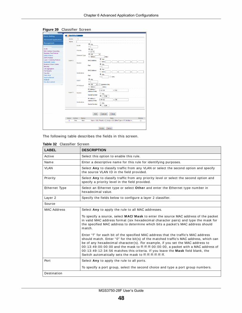
Chapter 6 Advanced Application Configurations
MGS3750-28F User’s Guide
48
Figure 39 Classifier Screen
The following table describes the fields in this screen.
Table 32 Classifier ScreenLABEL DESCRIPTION
Active Select this option to enable this rule.
Name Enter a descriptive name for this rule for identifying purposes.
VLAN Select Any to classify traffic from any VLAN or select the second option and specify the source VLAN ID in the field provided.
Priority Select Any to classify traffic from any priority level or select the second option and specify a priority level in the field provided.
Ethernet Type Select an Ethernet type or select Other and enter the Ethernet type number in hexadecimal value.
Layer 2 Specify the fields below to configure a layer 2 classifier.
Source
MAC Address Select Any to apply the rule to all MAC addresses.
To specify a source, select MAC/Mask to enter the source MAC address of the packet in valid MAC address format (six hexadecimal character pairs) and type the mask for the specified MAC address to determine which bits a packet’s MAC address should match.
Enter “f” for each bit of the specified MAC address that the traffic’s MAC address should match. Enter “0” for the bit(s) of the matched traffic’s MAC address, which can be of any hexadecimal character(s). For example, if you set the MAC address to 00:13:49:00:00:00 and the mask to ff:ff:ff:00:00:00, a packet with a MAC address of 00:13:49:12:34:56 matches this criteria. If you leave the Mask field blank, the Switch automatically sets the mask to ff:ff:ff:ff:ff:ff.
Port Select Any to apply the rule to all ports.
To specify a port group, select the second choice and type a port group numbers.
Destination
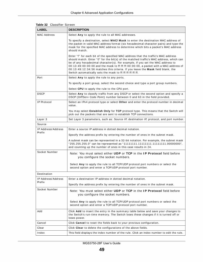
Chapter 6 Advanced Application Configurations
MGS3750-28F User’s Guide
49
MAC Address Select Any to apply the rule to all MAC addresses.
To specify a destination, select MAC/Mask to enter the destination MAC address of the packet in valid MAC address format (six hexadecimal character pairs) and type the mask for the specified MAC address to determine which bits a packet’s MAC address should match.
Enter “f” for each bit of the specified MAC address that the traffic’s MAC address should match. Enter “0” for the bit(s) of the matched traffic’s MAC address, which can be of any hexadecimal character(s). For example, if you set the MAC address to 00:13:49:00:00:00 and the mask to ff:ff:ff:00:00:00, a packet with a MAC address of 00:13:49:12:34:56 matches this criteria. If you leave the Mask field blank, the Switch automatically sets the mask to ff:ff:ff:ff:ff:ff.
Port Select Any to apply the rule to any ports.
To specify a port group, select the second choice and type a port group numbers.
Select CPU to apply the rule to the CPU port.
DSCP Select Any to classify traffic from any DSCP or select the second option and specify a DSCP (DiffServ Code Point) number between 0 and 63 in the field provided.
IP Protocol Select an IPv4 protocol type or select Other and enter the protocol number in decimal value.
You may select Establish Only for TCP protocol type. This means that the Switch will pick out the packets that are sent to establish TCP connections.
Layer 3 Set Layer 3 parameters, such as: Source IP, destination IP, protocol, and port number.
Source
IP Address/Address Prefix
Enter a source IP address in dotted decimal notation.
Specify the address prefix by entering the number of ones in the subnet mask.
A subnet mask can be represented in a 32-bit notation. For example, the subnet mask “255.255.255.0” can be represented as “11111111.11111111.11111111.00000000”, and counting up the number of ones in this case results in 24.
Socket Number Note: You must select either UDP or TCP in the IP Protocol field before you configure the socket numbers.
Select Any to apply the rule to all TCP/UDP protocol port numbers or select the second option and enter a TCP/UDP protocol port number.
Destination
IP Address/Address Prefix
Enter a destination IP address in dotted decimal notation.
Specify the address prefix by entering the number of ones in the subnet mask.
Socket Number Note: You must select either UDP or TCP in the IP Protocol field before you configure the socket numbers.
Select Any to apply the rule to all TCP/UDP protocol port numbers or select the second option and enter a TCP/UDP protocol port number.
Add Click Add to insert the entry in the summary table below and save your changes to the Switch’s run-time memory. The Switch loses these changes if it is turned off or loses power.
Cancel Click Cancel to reset the fields back to your previous configuration.
Clear Click Clear to delete the configurations of the above fields.
Index This field displays the index number of the rule. Click an index number to edit the rule.
Table 32 Classifier ScreenLABEL DESCRIPTION
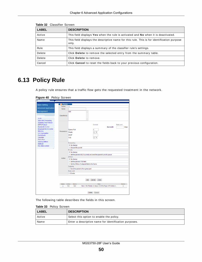
Chapter 6 Advanced Application Configurations
MGS3750-28F User’s Guide
50
6.13 Policy Rule
A policy rule ensures that a traffic flow gets the requested treatment in the network.
Figure 40 Policy Screen
The following table describes the fields in this screen.
Active This field displays Yes when the rule is activated and No when it is deactivated.
Name This field displays the descriptive name for this rule. This is for identification purpose only.
Rule This field displays a summary of the classifier rule’s settings.
Delete Click Delete to remove the selected entry from the summary table.
Delete Click Delete to remove.
Cancel Click Cancel to reset the fields back to your previous configuration.
Table 32 Classifier ScreenLABEL DESCRIPTION
Table 33 Policy ScreenLABEL DESCRIPTION
Active Select this option to enable the policy.
Name Enter a descriptive name for identification purposes.
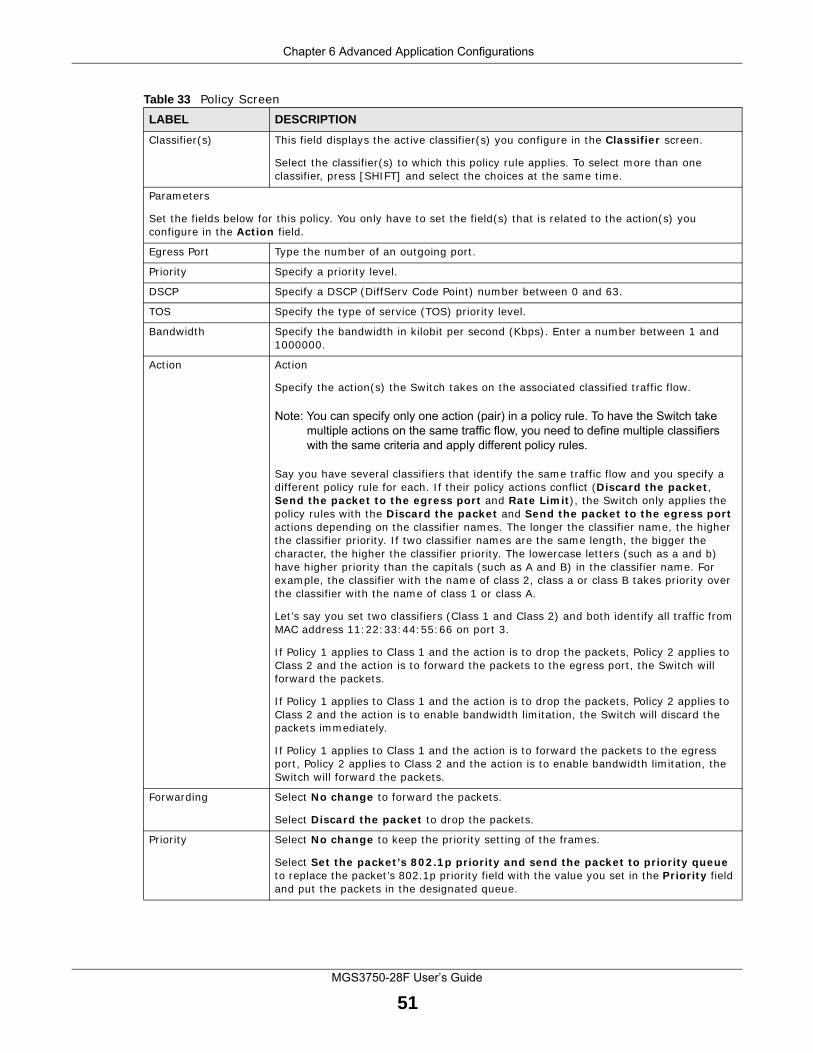
Chapter 6 Advanced Application Configurations
MGS3750-28F User’s Guide
51
Classifier(s) This field displays the active classifier(s) you configure in the Classifier screen.
Select the classifier(s) to which this policy rule applies. To select more than one classifier, press [SHIFT] and select the choices at the same time.
Parameters
Set the fields below for this policy. You only have to set the field(s) that is related to the action(s) you configure in the Action field.
Egress Port Type the number of an outgoing port.
Priority Specify a priority level.
DSCP Specify a DSCP (DiffServ Code Point) number between 0 and 63.
TOS Specify the type of service (TOS) priority level.
Bandwidth Specify the bandwidth in kilobit per second (Kbps). Enter a number between 1 and 1000000.
Action Action
Specify the action(s) the Switch takes on the associated classified traffic flow.
Note: You can specify only one action (pair) in a policy rule. To have the Switch take multiple actions on the same traffic flow, you need to define multiple classifiers with the same criteria and apply different policy rules.
Say you have several classifiers that identify the same traffic flow and you specify a different policy rule for each. If their policy actions conflict (Discard the packet, Send the packet to the egress port and Rate Limit), the Switch only applies the policy rules with the Discard the packet and Send the packet to the egress port actions depending on the classifier names. The longer the classifier name, the higher the classifier priority. If two classifier names are the same length, the bigger the character, the higher the classifier priority. The lowercase letters (such as a and b) have higher priority than the capitals (such as A and B) in the classifier name. For example, the classifier with the name of class 2, class a or class B takes priority over the classifier with the name of class 1 or class A.
Let’s say you set two classifiers (Class 1 and Class 2) and both identify all traffic from MAC address 11:22:33:44:55:66 on port 3.
If Policy 1 applies to Class 1 and the action is to drop the packets, Policy 2 applies to Class 2 and the action is to forward the packets to the egress port, the Switch will forward the packets.
If Policy 1 applies to Class 1 and the action is to drop the packets, Policy 2 applies to Class 2 and the action is to enable bandwidth limitation, the Switch will discard the packets immediately.
If Policy 1 applies to Class 1 and the action is to forward the packets to the egress port, Policy 2 applies to Class 2 and the action is to enable bandwidth limitation, the Switch will forward the packets.
Forwarding Select No change to forward the packets.
Select Discard the packet to drop the packets.
Priority Select No change to keep the priority setting of the frames.
Select Set the packet’s 802.1p priority and send the packet to priority queue to replace the packet’s 802.1p priority field with the value you set in the Priority field and put the packets in the designated queue.
Table 33 Policy ScreenLABEL DESCRIPTION
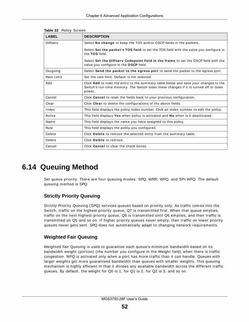
Chapter 6 Advanced Application Configurations
MGS3750-28F User’s Guide
52
6.14 Queuing Method
Set queue priority. There are four queuing modes: SPQ, WRR, WFQ, and SP+WFQ. The default queuing method is SPQ.
Strictly Priority Queuing
Strictly Priority Queuing (SPQ) services queues based on priority only. As traffic comes into the Switch, traffic on the highest priority queue, Q7 is transmitted first. When that queue empties, traffic on the next highest-priority queue, Q6 is transmitted until Q6 empties, and then traffic is transmitted on Q5 and so on. If higher priority queues never empty, then traffic on lower priority queues never gets sent. SPQ does not automatically adapt to changing network requirements.
Weighted Fair Queuing
Weighted Fair Queuing is used to guarantee each queue's minimum bandwidth based on its bandwidth weight (portion) (the number you configure in the Weight field) when there is traffic congestion. WFQ is activated only when a port has more traffic than it can handle. Queues with larger weights get more guaranteed bandwidth than queues with smaller weights. This queuing mechanism is highly efficient in that it divides any available bandwidth across the different traffic queues. By default, the weight for Q0 is 1, for Q1 is 2, for Q2 is 3, and so on.
Diffserv Select No change to keep the TOS and/or DSCP fields in the packets.
Select Set the packet’s TOS field to set the TOS field with the value you configure in the TOS field.
Select Set the Diffserv Codepoint field in the frame to set the DSCP field with the value you configure in the DSCP field.
Outgoing Select Send the packet to the egress port to send the packet to the egress port.
Rate Limit Set the rate limit. Default is not selected.
Add Click Add to inset the entry to the summary table below and save your changes to the Switch’s run-time memory. The Switch loses these changes if it is turned off or loses power.
Cancel Click Cancel to reset the fields back to your previous configuration.
Clear Click Clear to delete the configurations of the above fields.
Index This field displays the policy index number. Click an index number to edit the policy.
Active This field displays Yes when policy is activated and No when is it deactivated.
Name This field displays the name you have assigned to this policy.
Rule This field displays the policy you configured.
Delete Click Delete to remove the selected entry from the summary table.
Delete Click Delete to remove.
Cancel Click Cancel to clear the check boxes.
Table 33 Policy ScreenLABEL DESCRIPTION
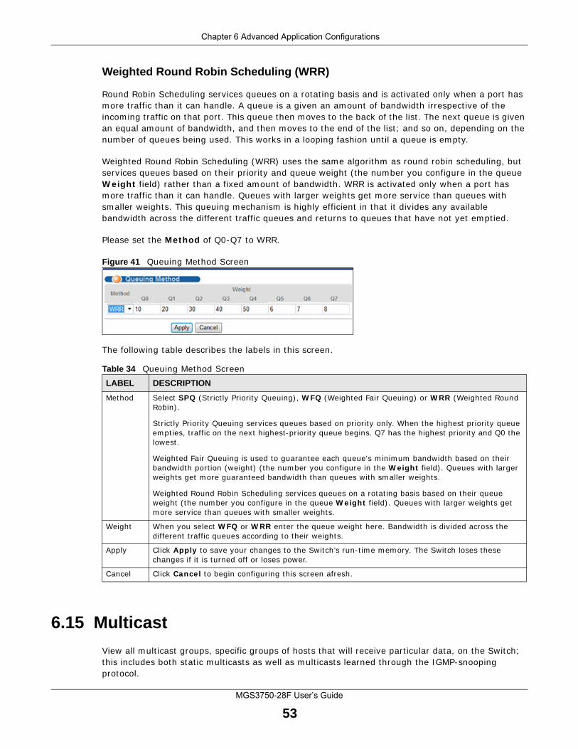
Chapter 6 Advanced Application Configurations
MGS3750-28F User’s Guide
53
Weighted Round Robin Scheduling (WRR)
Round Robin Scheduling services queues on a rotating basis and is activated only when a port has more traffic than it can handle. A queue is a given an amount of bandwidth irrespective of the incoming traffic on that port. This queue then moves to the back of the list. The next queue is given an equal amount of bandwidth, and then moves to the end of the list; and so on, depending on the number of queues being used. This works in a looping fashion until a queue is empty.
Weighted Round Robin Scheduling (WRR) uses the same algorithm as round robin scheduling, but services queues based on their priority and queue weight (the number you configure in the queue Weight field) rather than a fixed amount of bandwidth. WRR is activated only when a port has more traffic than it can handle. Queues with larger weights get more service than queues with smaller weights. This queuing mechanism is highly efficient in that it divides any available bandwidth across the different traffic queues and returns to queues that have not yet emptied.
Please set the Method of Q0-Q7 to WRR.
Figure 41 Queuing Method Screen
The following table describes the labels in this screen.
6.15 Multicast
View all multicast groups, specific groups of hosts that will receive particular data, on the Switch; this includes both static multicasts as well as multicasts learned through the IGMP-snooping protocol.
Table 34 Queuing Method ScreenLABEL DESCRIPTION
Method Select SPQ (Strictly Priority Queuing), WFQ (Weighted Fair Queuing) or WRR (Weighted Round Robin).
Strictly Priority Queuing services queues based on priority only. When the highest priority queue empties, traffic on the next highest-priority queue begins. Q7 has the highest priority and Q0 the lowest.
Weighted Fair Queuing is used to guarantee each queue's minimum bandwidth based on their bandwidth portion (weight) (the number you configure in the Weight field). Queues with larger weights get more guaranteed bandwidth than queues with smaller weights.
Weighted Round Robin Scheduling services queues on a rotating basis based on their queue weight (the number you configure in the queue Weight field). Queues with larger weights get more service than queues with smaller weights.
Weight When you select WFQ or WRR enter the queue weight here. Bandwidth is divided across the different traffic queues according to their weights.
Apply Click Apply to save your changes to the Switch’s run-time memory. The Switch loses these changes if it is turned off or loses power.
Cancel Click Cancel to begin configuring this screen afresh.
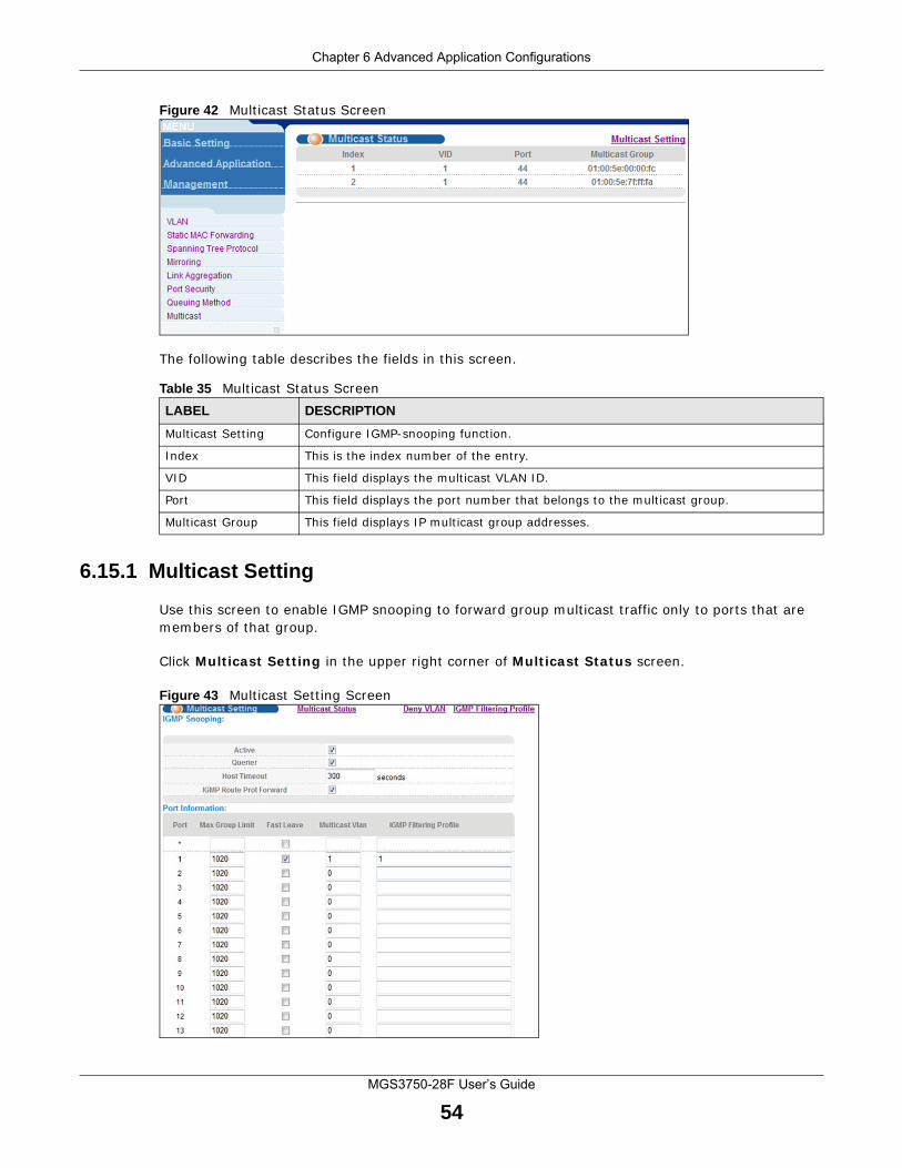
Chapter 6 Advanced Application Configurations
MGS3750-28F User’s Guide
54
Figure 42 Multicast Status Screen
The following table describes the fields in this screen.
6.15.1 Multicast Setting
Use this screen to enable IGMP snooping to forward group multicast traffic only to ports that are members of that group.
Click Multicast Setting in the upper right corner of Multicast Status screen.
Figure 43 Multicast Setting Screen
Table 35 Multicast Status ScreenLABEL DESCRIPTION
Multicast Setting Configure IGMP-snooping function.
Index This is the index number of the entry.
VID This field displays the multicast VLAN ID.
Port This field displays the port number that belongs to the multicast group.
Multicast Group This field displays IP multicast group addresses.
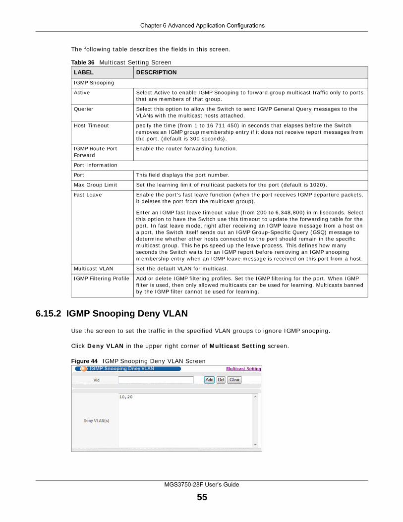
Chapter 6 Advanced Application Configurations
MGS3750-28F User’s Guide
55
The following table describes the fields in this screen.
6.15.2 IGMP Snooping Deny VLAN
Use the screen to set the traffic in the specified VLAN groups to ignore IGMP snooping.
Click Deny VLAN in the upper right corner of Multicast Setting screen.
Figure 44 IGMP Snooping Deny VLAN Screen
Table 36 Multicast Setting ScreenLABEL DESCRIPTION
IGMP Snooping
Active Select Active to enable IGMP Snooping to forward group multicast traffic only to ports that are members of that group.
Querier Select this option to allow the Switch to send IGMP General Query messages to the VLANs with the multicast hosts attached.
Host Timeout pecify the time (from 1 to 16 711 450) in seconds that elapses before the Switch removes an IGMP group membership entry if it does not receive report messages from the port. (default is 300 seconds).
IGMP Route Port Forward
Enable the router forwarding function.
Port Information
Port This field displays the port number.
Max Group Limit Set the learning limit of multicast packets for the port (default is 1020).
Fast Leave Enable the port's fast leave function (when the port receives IGMP departure packets, it deletes the port from the multicast group).
Enter an IGMP fast leave timeout value (from 200 to 6,348,800) in miliseconds. Select this option to have the Switch use this timeout to update the forwarding table for the port. In fast leave mode, right after receiving an IGMP leave message from a host on a port, the Switch itself sends out an IGMP Group-Specific Query (GSQ) message to determine whether other hosts connected to the port should remain in the specific multicast group. This helps speed up the leave process. This defines how many seconds the Switch waits for an IGMP report before removing an IGMP snooping membership entry when an IGMP leave message is received on this port from a host.
Multicast VLAN Set the default VLAN for multicast.
IGMP Filtering Profile Add or delete IGMP filtering profiles. Set the IGMP filtering for the port. When IGMP filter is used, then only allowed multicasts can be used for learning. Multicasts banned by the IGMP filter cannot be used for learning.
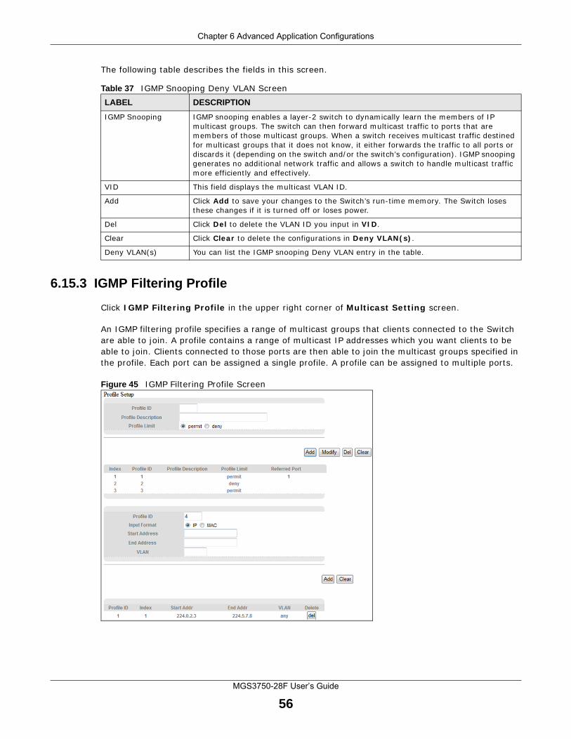
Chapter 6 Advanced Application Configurations
MGS3750-28F User’s Guide
56
The following table describes the fields in this screen.
6.15.3 IGMP Filtering Profile
Click IGMP Filtering Profile in the upper right corner of Multicast Setting screen.
An IGMP filtering profile specifies a range of multicast groups that clients connected to the Switch are able to join. A profile contains a range of multicast IP addresses which you want clients to be able to join. Clients connected to those ports are then able to join the multicast groups specified in the profile. Each port can be assigned a single profile. A profile can be assigned to multiple ports.
Figure 45 IGMP Filtering Profile Screen
Table 37 IGMP Snooping Deny VLAN ScreenLABEL DESCRIPTION
IGMP Snooping IGMP snooping enables a layer-2 switch to dynamically learn the members of IP multicast groups. The switch can then forward multicast traffic to ports that are members of those multicast groups. When a switch receives multicast traffic destined for multicast groups that it does not know, it either forwards the traffic to all ports or discards it (depending on the switch and/or the switch’s configuration). IGMP snooping generates no additional network traffic and allows a switch to handle multicast traffic more efficiently and effectively.
VID This field displays the multicast VLAN ID.
Add Click Add to save your changes to the Switch’s run-time memory. The Switch loses these changes if it is turned off or loses power.
Del Click Del to delete the VLAN ID you input in VID.
Clear Click Clear to delete the configurations in Deny VLAN(s).
Deny VLAN(s) You can list the IGMP snooping Deny VLAN entry in the table.
Chapter 6 Advanced Application Configurations
MGS3750-28F User’s Guide
57
The following table describes the fields in this screen.
6.16 CPU Queue Control
Use this screen to control the rate at which packets are passed to the CPU.
Table 38 IGMP Filtering Profile ScreenLABEL DESCRIPTION
Profile Setup Add IGMP filtering profile.
Profile ID The profile ID can be between 1-128.
Profile Description You can add descriptions to a profile in this field.
Profile Limit Profile rule can be either permit or deny.
Add Click Add to save your changes to the Switch’s run-time memory. The Switch loses these changes if it is turned off or loses power.
Modify Click Modify to make changes to a profile ID.
Del Click Del to delete a profile ID and the rules applied to it.
Clear Click Clear to delete the configurations of the fields.
Index This is the index number of a IGMP filtering profile entry. Click this number to edit the entry.
Profile ID The profile ID can be between 1-128.
Profile Description This field displays the profile description you’ve given to the profile ID.
Profile Limit You can choose to permit or deny the profile.
Referred Port This field displays the port with the referred rules.
Profile ID The profile ID can be between 1-128.
Input Format Filter address can be set as IP or MAC address.
Start Address Type the starting multicast IP address for a range of multicast IP addresses that you want to belong to the IGMP filter profile.
End Address Type the ending multicast IP address for a range of IP addresses that you want to belong to the IGMP filter profile.
If you want to add a single multicast IP address, enter it in both the Start Address and End Address fields.
VLAN Input a VLAN group number.
Add Click this to create a new entry.
This saves your changes to the Switch’s run-time memory. The Switch loses these changes if it is turned off or loses power.
Clear Click Clear to delete the configurations of the fields.
Profile ID Thie field displays the profile ID.
Index Thie field displays the index number.
Start Addr This field displays the starting multicast IP address that you want to belong to the IGMP filter profile.
End Addr This field displays the ending multicast IP address that you want to belong to the IGMP filter profile.
VLAN This field displays the VLAN ID with the IGMP filtering profile.
Delete Click Del to delete a profile ID.
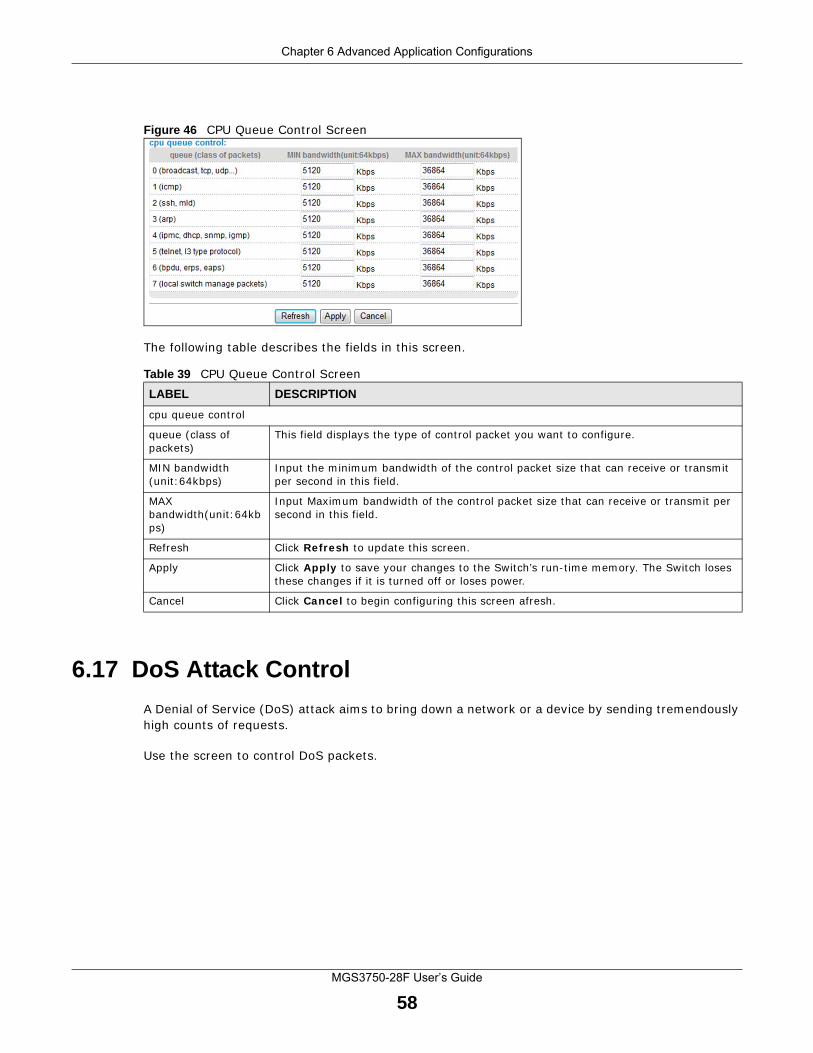
Chapter 6 Advanced Application Configurations
MGS3750-28F User’s Guide
58
Figure 46 CPU Queue Control Screen
The following table describes the fields in this screen.
6.17 DoS Attack Control
A Denial of Service (DoS) attack aims to bring down a network or a device by sending tremendously high counts of requests.
Use the screen to control DoS packets.
Table 39 CPU Queue Control ScreenLABEL DESCRIPTION
cpu queue control
queue (class of packets)
This field displays the type of control packet you want to configure.
MIN bandwidth (unit:64kbps)
Input the minimum bandwidth of the control packet size that can receive or transmit per second in this field.
MAX bandwidth(unit:64kbps)
Input Maximum bandwidth of the control packet size that can receive or transmit per second in this field.
Refresh Click Refresh to update this screen.
Apply Click Apply to save your changes to the Switch’s run-time memory. The Switch loses these changes if it is turned off or loses power.
Cancel Click Cancel to begin configuring this screen afresh.
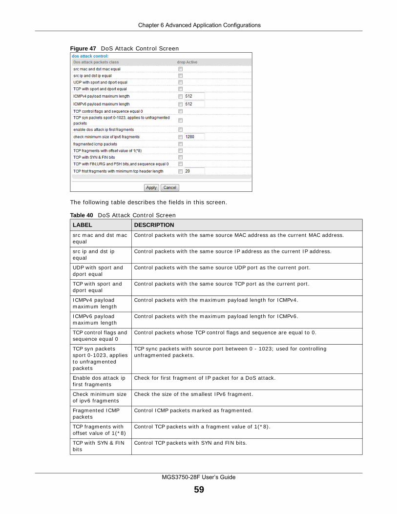
Chapter 6 Advanced Application Configurations
MGS3750-28F User’s Guide
59
Figure 47 DoS Attack Control Screen
The following table describes the fields in this screen.
Table 40 DoS Attack Control ScreenLABEL DESCRIPTION
src mac and dst mac equal
Control packets with the same source MAC address as the current MAC address.
src ip and dst ip equal
Control packets with the same source IP address as the current IP address.
UDP with sport and dport equal
Control packets with the same source UDP port as the current port.
TCP with sport and dport equal
Control packets with the same source TCP port as the current port.
ICMPv4 payload maximum length
Control packets with the maximum payload length for ICMPv4.
ICMPv6 payload maximum length
Control packets with the maximum payload length for ICMPv6.
TCP control flags and sequence equal 0
Control packets whose TCP control flags and sequence are equal to 0.
TCP syn packets sport 0-1023, applies to unfragmented packets
TCP sync packets with source port between 0 - 1023; used for controlling unfragmented packets.
Enable dos attack ip first fragments
Check for first fragment of IP packet for a DoS attack.
Check minimum size of ipv6 fragments
Check the size of the smallest IPv6 fragment.
Fragmented ICMP packets
Control ICMP packets marked as fragmented.
TCP fragments with offset value of 1(*8)
Control TCP packets with a fragment value of 1(*8).
TCP with SYN & FIN bits
Control TCP packets with SYN and FIN bits.
Chapter 6 Advanced Application Configurations
MGS3750-28F User’s Guide
60
TCP with FIN,URG and PSH bits,and sequence equal 0
Control TCP packets with FIN, URG, and PSH bits whose sequence = 0.
TCP first fragments with minimum tcp header length
Control TCP packets where the first fragment has the minimum TCP header length.
Table 40 DoS Attack Control ScreenLABEL DESCRIPTION
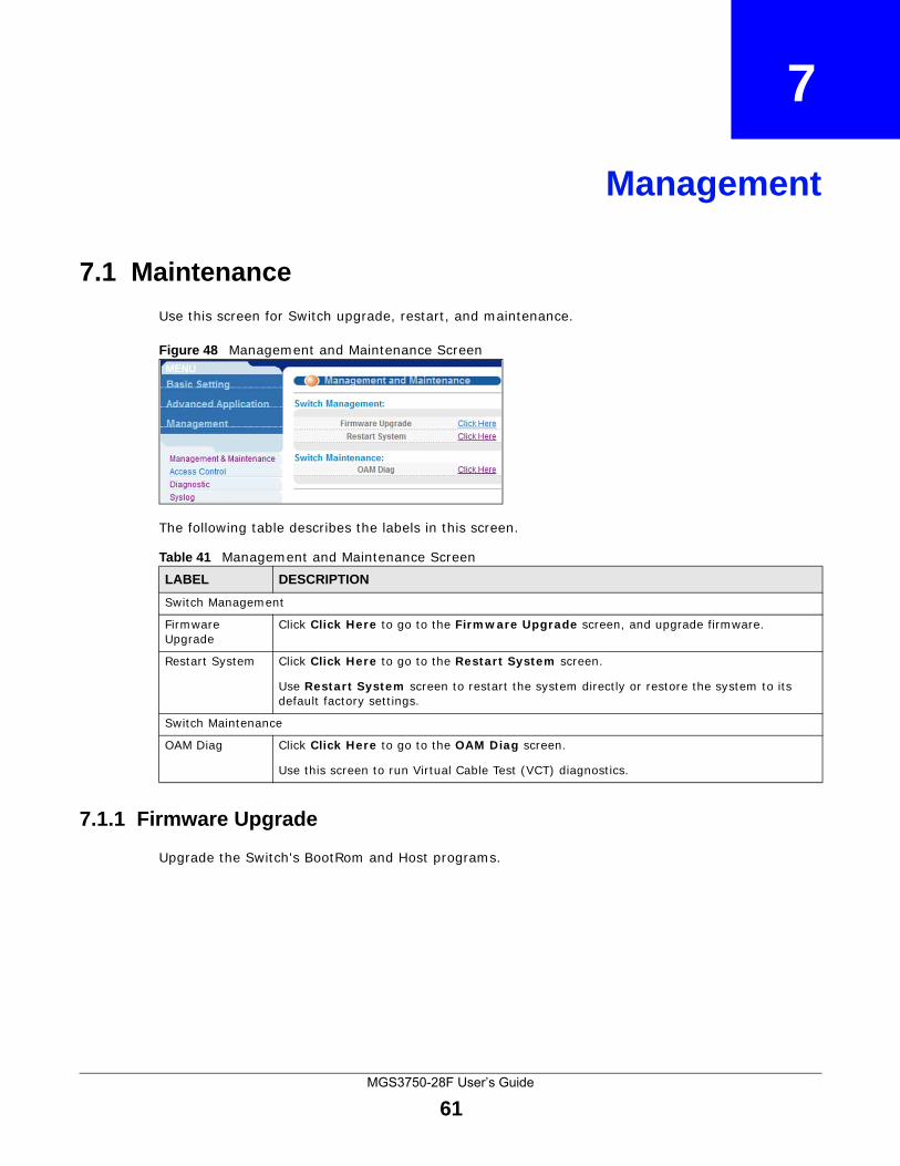
MGS3750-28F User’s Guide
61
CHAPTER 7
Management
7.1 Maintenance
Use this screen for Switch upgrade, restart, and maintenance.
Figure 48 Management and Maintenance Screen
The following table describes the labels in this screen.
7.1.1 Firmware Upgrade
Upgrade the Switch's BootRom and Host programs.
Table 41 Management and Maintenance Screen LABEL DESCRIPTION
Switch Management
Firmware Upgrade
Click Click Here to go to the Firmware Upgrade screen, and upgrade firmware.
Restart System Click Click Here to go to the Restart System screen.
Use Restart System screen to restart the system directly or restore the system to its default factory settings.
Switch Maintenance
OAM Diag Click Click Here to go to the OAM Diag screen.
Use this screen to run Virtual Cable Test (VCT) diagnostics.
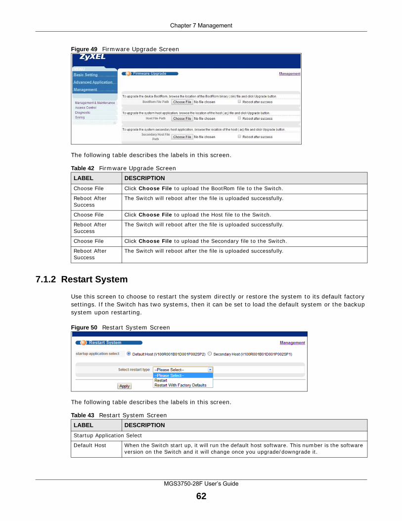
Chapter 7 Management
MGS3750-28F User’s Guide
62
Figure 49 Firmware Upgrade Screen
The following table describes the labels in this screen.
7.1.2 Restart System
Use this screen to choose to restart the system directly or restore the system to its default factory settings. If the Switch has two systems, then it can be set to load the default system or the backup system upon restarting.
Figure 50 Restart System Screen
The following table describes the labels in this screen.
Table 42 Firmware Upgrade Screen LABEL DESCRIPTION
Choose File Click Choose File to upload the BootRom file to the Switch.
Reboot After Success
The Switch will reboot after the file is uploaded successfully.
Choose File Click Choose File to upload the Host file to the Switch.
Reboot After Success
The Switch will reboot after the file is uploaded successfully.
Choose File Click Choose File to upload the Secondary file to the Switch.
Reboot After Success
The Switch will reboot after the file is uploaded successfully.
Table 43 Restart System Screen LABEL DESCRIPTION
Startup Application Select
Default Host When the Switch start up, it will run the default host software. This number is the software version on the Switch and it will change once you upgrade/downgrade it.
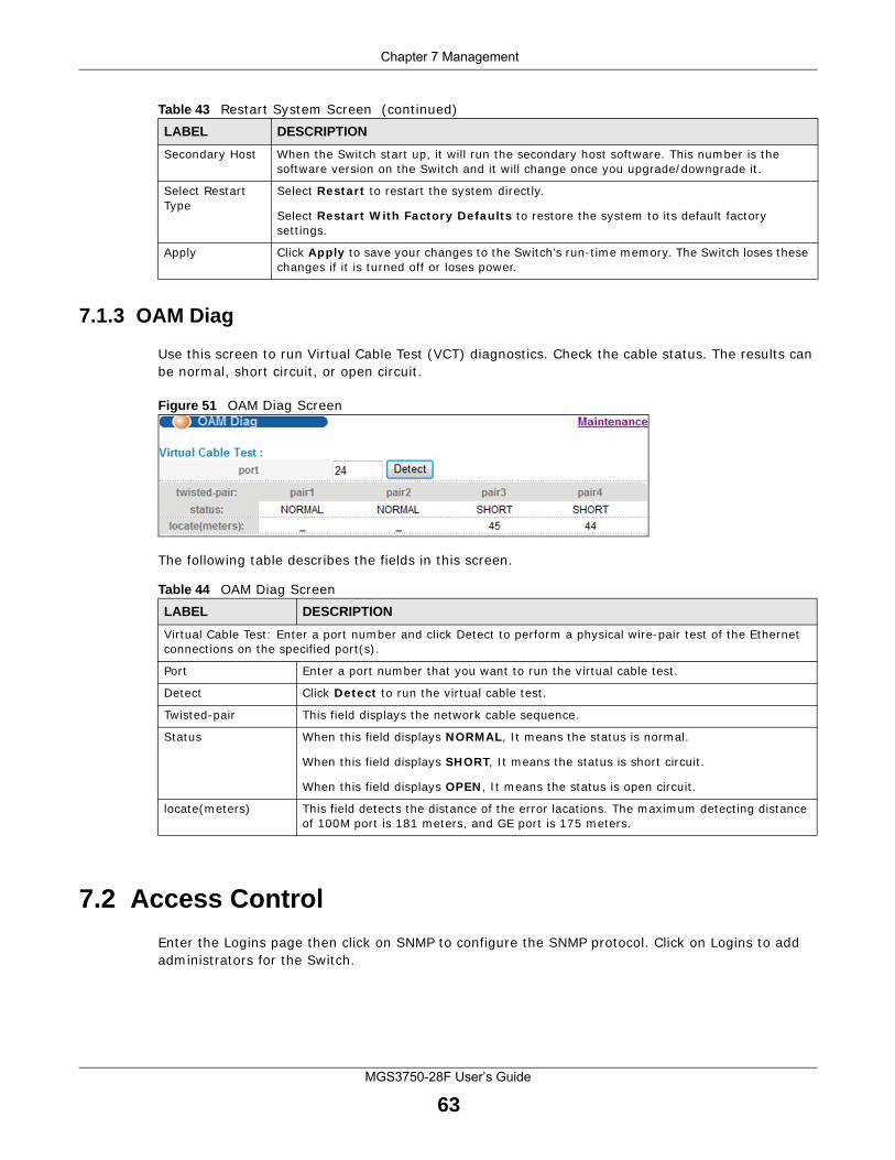
Chapter 7 Management
MGS3750-28F User’s Guide
63
7.1.3 OAM Diag
Use this screen to run Virtual Cable Test (VCT) diagnostics. Check the cable status. The results can be normal, short circuit, or open circuit.
Figure 51 OAM Diag Screen
The following table describes the fields in this screen.
7.2 Access Control
Enter the Logins page then click on SNMP to configure the SNMP protocol. Click on Logins to add administrators for the Switch.
Secondary Host When the Switch start up, it will run the secondary host software. This number is the software version on the Switch and it will change once you upgrade/downgrade it.
Select Restart Type
Select Restart to restart the system directly.
Select Restart With Factory Defaults to restore the system to its default factory settings.
Apply Click Apply to save your changes to the Switch’s run-time memory. The Switch loses these changes if it is turned off or loses power.
Table 43 Restart System Screen (continued)LABEL DESCRIPTION
Table 44 OAM Diag ScreenLABEL DESCRIPTION
Virtual Cable Test: Enter a port number and click Detect to perform a physical wire-pair test of the Ethernet connections on the specified port(s).
Port Enter a port number that you want to run the virtual cable test.
Detect Click Detect to run the virtual cable test.
Twisted-pair This field displays the network cable sequence.
Status When this field displays NORMAL, It means the status is normal.
When this field displays SHORT, It means the status is short circuit.
When this field displays OPEN, It means the status is open circuit.
locate(meters) This field detects the distance of the error lacations. The maximum detecting distance of 100M port is 181 meters, and GE port is 175 meters.
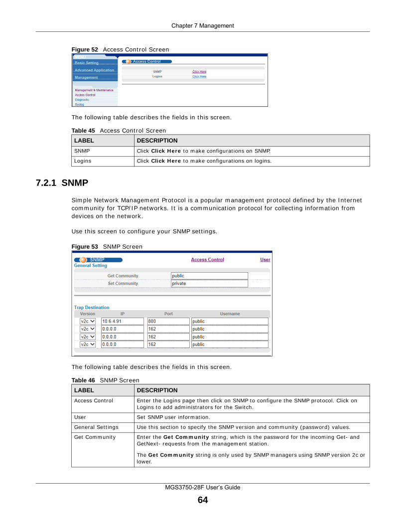
Chapter 7 Management
MGS3750-28F User’s Guide
64
Figure 52 Access Control Screen
The following table describes the fields in this screen.
7.2.1 SNMP
Simple Network Management Protocol is a popular management protocol defined by the Internet community for TCP/IP networks. It is a communication protocol for collecting information from devices on the network.
Use this screen to configure your SNMP settings.
Figure 53 SNMP Screen
The following table describes the fields in this screen.
Table 45 Access Control ScreenLABEL DESCRIPTION
SNMP Click Click Here to make configurations on SNMP.
Logins Click Click Here to make configurations on logins.
Table 46 SNMP ScreenLABEL DESCRIPTION
Access Control Enter the Logins page then click on SNMP to configure the SNMP protocol. Click on Logins to add administrators for the Switch.
User Set SNMP user information.
General Settings Use this section to specify the SNMP version and community (password) values.
Get Community Enter the Get Community string, which is the password for the incoming Get- and GetNext- requests from the management station.
The Get Community string is only used by SNMP managers using SNMP version 2c or lower.
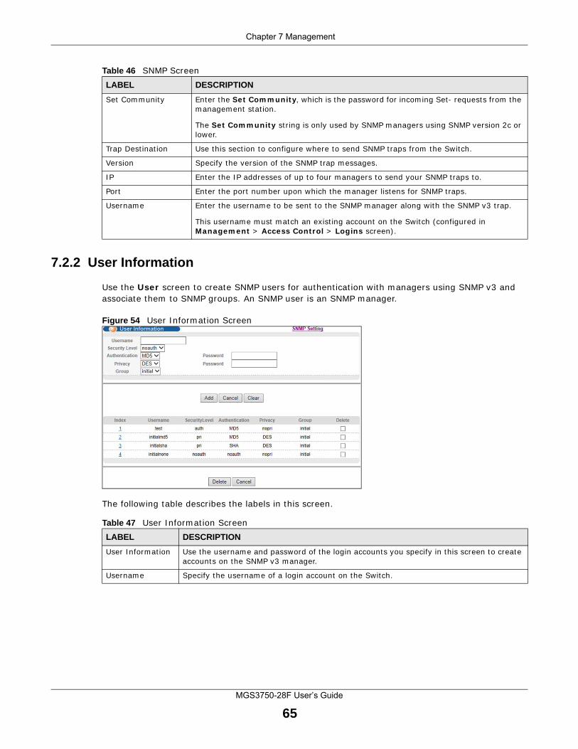
Chapter 7 Management
MGS3750-28F User’s Guide
65
7.2.2 User Information
Use the User screen to create SNMP users for authentication with managers using SNMP v3 and associate them to SNMP groups. An SNMP user is an SNMP manager.
Figure 54 User Information Screen
The following table describes the labels in this screen.
Set Community Enter the Set Community, which is the password for incoming Set- requests from the management station.
The Set Community string is only used by SNMP managers using SNMP version 2c or lower.
Trap Destination Use this section to configure where to send SNMP traps from the Switch.
Version Specify the version of the SNMP trap messages.
IP Enter the IP addresses of up to four managers to send your SNMP traps to.
Port Enter the port number upon which the manager listens for SNMP traps.
Username Enter the username to be sent to the SNMP manager along with the SNMP v3 trap.
This username must match an existing account on the Switch (configured in Management > Access Control > Logins screen).
Table 46 SNMP ScreenLABEL DESCRIPTION
Table 47 User Information ScreenLABEL DESCRIPTION
User Information Use the username and password of the login accounts you specify in this screen to create accounts on the SNMP v3 manager.
Username Specify the username of a login account on the Switch.
Chapter 7 Management
MGS3750-28F User’s Guide
66
Security Level Select whether you want to implement authentication and/or encryption for SNMP communication from this user. Choose:
• noauth -to use the username as the password string to send to the SNMP manager. This is equivalent to the Get, Set and Trap Community in SNMP v2c. This is the lowest security level.
• auth - to implement an authentication algorithm for SNMP messages sent by this user.
• priv - to implement authentication and encryption for SNMP messages sent by this user. This is the highest security level.
Note: The settings on the SNMP manager must be set at the same security level or higher than the security level settings on the Switch.
Authentication Select an authentication algorithm. MD5 (Message Digest 5) and SHA (Secure Hash Algorithm) are hash algorithms used to authenticate SNMP data. SHA authentication is generally considered stronger than MD5, but is slower.
Password Enter the password of up to 32 ASCII characters for SNMP user authentication.
Privacy Specify the encryption method for SNMP communication from this user. You can choose one of the following:
• DES - Data Encryption Standard is a widely used (but breakable) method of data encryption. It applies a 56-bit key to each 64-bit block of data.
• AES - Advanced Encryption Standard is another method for data encryption that also uses a secret key. AES applies a 128-bit key to 128-bit blocks of data.
Password Enter the password of up to 32 ASCII characters for encrypting SNMP packets.
Group SNMP v3 adopts the concept of View-based Access Control Model (VACM) group. SNMP managers in one group are assigned common access rights to MIBs. Specify in which SNMP group this user is.
admin - Members of this group can perform all types of system configuration, including the management of administrator accounts.
readwrite - Members of this group have read and write rights, meaning that the user can create and edit the MIBs on the Switch, except the user account and AAA configuration.
readonly - Members of this group have read rights only, meaning the user can collect information from the Switch.
Add Click this to create a new entry or to update an existing one.
This saves your changes to the Switch’s run-time memory. The Switch loses these changes if it is turned off or loses power.
Cancel Click Cancel to reset the fields to your previous configuration.
Clear Click Clear to reset the fields to the factory defaults.
Index This is a read-only number identifying a login account on the Switch. Click on an index number to view more details and edit an existing account.
Username This field displays the username of a login account on the Switch.
Security Level This field displays whether you want to implement authentication and/or encryption for SNMP communication with this user.
Authentication This field displays the authentication algorithm used for SNMP communication with this user.
Privacy This field displays the encryption method used for SNMP communication with this user.
Group This field displays the SNMP group to which this user belongs.
Delete Click Delete to remove the selected entry from the summary table.
Delete Click Delete to remove.
Cancel Click Cancel to begin configuring this screen afresh.
Table 47 User Information Screen (continued)LABEL DESCRIPTION
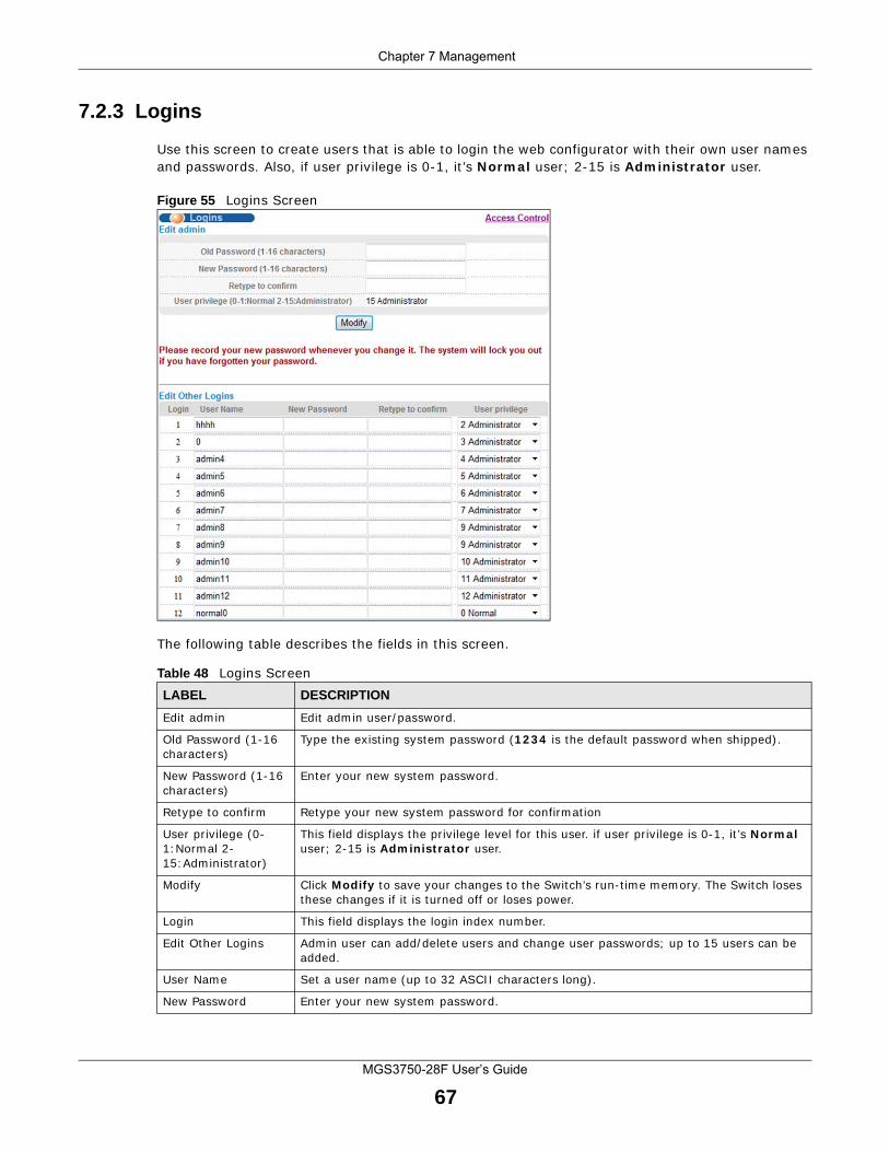
Chapter 7 Management
MGS3750-28F User’s Guide
67
7.2.3 Logins
Use this screen to create users that is able to login the web configurator with their own user names and passwords. Also, if user privilege is 0-1, it’s Normal user; 2-15 is Administrator user.
Figure 55 Logins Screen
The following table describes the fields in this screen.
Table 48 Logins ScreenLABEL DESCRIPTION
Edit admin Edit admin user/password.
Old Password (1-16 characters)
Type the existing system password (1234 is the default password when shipped).
New Password (1-16 characters)
Enter your new system password.
Retype to confirm Retype your new system password for confirmation
User privilege (0-1:Normal 2-15:Administrator)
This field displays the privilege level for this user. if user privilege is 0-1, it’s Normal user; 2-15 is Administrator user.
Modify Click Modify to save your changes to the Switch’s run-time memory. The Switch loses these changes if it is turned off or loses power.
Login This field displays the login index number.
Edit Other Logins Admin user can add/delete users and change user passwords; up to 15 users can be added.
User Name Set a user name (up to 32 ASCII characters long).
New Password Enter your new system password.
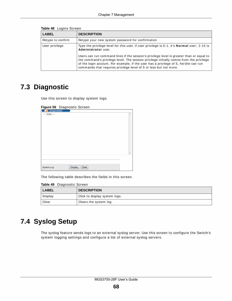
Chapter 7 Management
MGS3750-28F User’s Guide
68
7.3 Diagnostic
Use this screen to display system logs.
Figure 56 Diagnostic Screen
The following table describes the fields in this screen.
7.4 Syslog Setup
The syslog feature sends logs to an external syslog server. Use this screen to configure the Switch’s system logging settings and configure a list of external syslog servers.
Retype to confirm Retype your new system password for confirmation
User privilege Type the privilege level for this user. if user privilege is 0-1, it’s Normal user; 2-15 is Administrator user.
Users can run command lines if the session’s privilege level is greater than or equal to the command’s privilege level. The session privilege initially comes from the privilege of the login account. For example, if the user has a privilege of 5, he/she can run commands that requires privilege level of 5 or less but not more.
Table 48 Logins ScreenLABEL DESCRIPTION
Table 49 Diagnostic ScreenLABEL DESCRIPTION
Display Click to display system logs.
Clear Clears the system log.
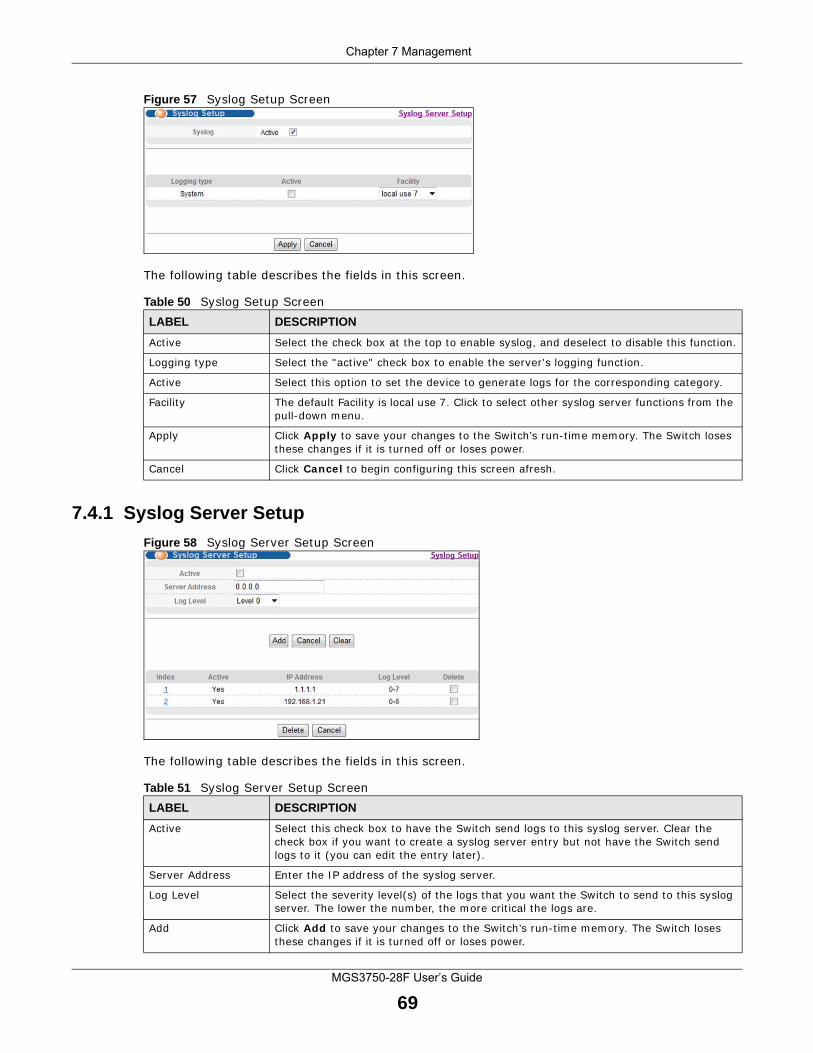
Chapter 7 Management
MGS3750-28F User’s Guide
69
Figure 57 Syslog Setup Screen
The following table describes the fields in this screen.
7.4.1 Syslog Server Setup
Figure 58 Syslog Server Setup Screen
The following table describes the fields in this screen.
Table 50 Syslog Setup ScreenLABEL DESCRIPTION
Active Select the check box at the top to enable syslog, and deselect to disable this function.
Logging type Select the "active" check box to enable the server's logging function.
Active Select this option to set the device to generate logs for the corresponding category.
Facility The default Facility is local use 7. Click to select other syslog server functions from the pull-down menu.
Apply Click Apply to save your changes to the Switch’s run-time memory. The Switch loses these changes if it is turned off or loses power.
Cancel Click Cancel to begin configuring this screen afresh.
Table 51 Syslog Server Setup ScreenLABEL DESCRIPTION
Active Select this check box to have the Switch send logs to this syslog server. Clear the check box if you want to create a syslog server entry but not have the Switch send logs to it (you can edit the entry later).
Server Address Enter the IP address of the syslog server.
Log Level Select the severity level(s) of the logs that you want the Switch to send to this syslog server. The lower the number, the more critical the logs are.
Add Click Add to save your changes to the Switch’s run-time memory. The Switch loses these changes if it is turned off or loses power.
Chapter 7 Management
MGS3750-28F User’s Guide
70
Cancel Click Cancel to begin configuring this screen afresh.
Clear Click Clear to return the fields to the factory defaults.
Index This is the index number of a syslog server entry. Click this number to edit the entry.
Active This field displays Yes if the Switch is to send logs to the syslog server. No displays if the Switch is not to send logs to the syslog server.
IP Address This field displays the IP address of the syslog server.
Log Level This field displays the severity level of the logs that the Switch is to send to this syslog server.
Delete Click Delete to remove the selected entry(ies).
Delete Click Delete to remove.
Cancel Click Cancel to begin configuring this screen afresh.
Table 51 Syslog Server Setup ScreenLABEL DESCRIPTION
MGS3750-28F User’s Guide
71
APPENDIX A
Customer Support
In the event of problems that cannot be solved by using this manual, you should contact your vendor. If you cannot contact your vendor, then contact a ZyXEL office for the region in which you bought the device.
See http://www.zyxel.com/homepage.shtml and also
http://www.zyxel.com/about_zyxel/zyxel_worldwide.shtml for the latest information.
Please have the following information ready when you contact an office.
Required Information
• Product model and serial number.
• Warranty Information.
• Date that you received your device.
• Brief description of the problem and the steps you took to solve it.
Corporate Headquarters (Worldwide)
Taiwan
• ZyXEL Communications Corporation
• http://www.zyxel.com
Asia
China
• ZyXEL Communications (Shanghai) Corp.
ZyXEL Communications (Beijing) Corp.
ZyXEL Communications (Tianjin) Corp.
• http://www.zyxel.cn
India
• ZyXEL Technology India Pvt Ltd
• http://www.zyxel.in
Kazakhstan
• ZyXEL Kazakhstan
Appendix A Customer Support
MGS3750-28F User’s Guide
72
• http://www.zyxel.kz
Korea
• ZyXEL Korea Corp.
• http://www.zyxel.kr
Malaysia
• ZyXEL Malaysia Sdn Bhd.
• http://www.zyxel.com.my
Pakistan
• ZyXEL Pakistan (Pvt.) Ltd.
• http://www.zyxel.com.pk
Philippines
• ZyXEL Philippines
• http://www.zyxel.com.ph
Singapore
• ZyXEL Singapore Pte Ltd.
• http://www.zyxel.com.sg
Taiwan
• ZyXEL Communications Corporation
• http://www.zyxel.com/tw/zh/
Thailand
• ZyXEL Thailand Co., Ltd
• http://www.zyxel.co.th
Vietnam
• ZyXEL Communications Corporation-Vietnam Office
• http://www.zyxel.com/vn/vi
Europe
Austria
• ZyXEL Deutschland GmbH
• http://www.zyxel.de
Belarus
• ZyXEL BY
Appendix A Customer Support
MGS3750-28F User’s Guide
73
• http://www.zyxel.by
Belgium
• ZyXEL Communications B.V.
• http://www.zyxel.com/be/nl/
• http://www.zyxel.com/be/fr/
Bulgaria
• ZyXEL България
• http://www.zyxel.com/bg/bg/
Czech Republic
• ZyXEL Communications Czech s.r.o
• http://www.zyxel.cz
Denmark
• ZyXEL Communications A/S
• http://www.zyxel.dk
Estonia
• ZyXEL Estonia
• http://www.zyxel.com/ee/et/
Finland
• ZyXEL Communications
• http://www.zyxel.fi
France
• ZyXEL France
• http://www.zyxel.fr
Germany
• ZyXEL Deutschland GmbH
• http://www.zyxel.de
Hungary
• ZyXEL Hungary & SEE
• http://www.zyxel.hu
Italy
• ZyXEL Communications Italy
• http://www.zyxel.it/
Appendix A Customer Support
MGS3750-28F User’s Guide
74
Latvia
• ZyXEL Latvia
• http://www.zyxel.com/lv/lv/homepage.shtml
Lithuania
• ZyXEL Lithuania
• http://www.zyxel.com/lt/lt/homepage.shtml
Netherlands
• ZyXEL Benelux
• http://www.zyxel.nl
Norway
• ZyXEL Communications
• http://www.zyxel.no
Poland
• ZyXEL Communications Poland
• http://www.zyxel.pl
Romania
• ZyXEL Romania
• http://www.zyxel.com/ro/ro
Russia
• ZyXEL Russia
• http://www.zyxel.ru
Slovakia
• ZyXEL Communications Czech s.r.o. organizacna zlozka
• http://www.zyxel.sk
Spain
• ZyXEL Communications ES Ltd
• http://www.zyxel.es
Sweden
• ZyXEL Communications
• http://www.zyxel.se
Switzerland
• Studerus AG
Appendix A Customer Support
MGS3750-28F User’s Guide
75
• http://www.zyxel.ch/
Turkey
• ZyXEL Turkey A.S.
• http://www.zyxel.com.tr
UK
• ZyXEL Communications UK Ltd.
• http://www.zyxel.co.uk
Ukraine
• ZyXEL Ukraine
• http://www.ua.zyxel.com
Latin America
Argentina
• ZyXEL Communication Corporation
• http://www.zyxel.com/ec/es/
Brazil
• ZyXEL Communications Brasil Ltda.
• https://www.zyxel.com/br/pt/
Ecuador
• ZyXEL Communication Corporation
• http://www.zyxel.com/ec/es/
Middle East
Israel
• ZyXEL Communication Corporation
• http://il.zyxel.com/homepage.shtml
Middle East
• ZyXEL Communication Corporation
• http://www.zyxel.com/me/en/
Appendix A Customer Support
MGS3750-28F User’s Guide
76
North America
USA
• ZyXEL Communications, Inc. - North America Headquarters
• http://www.zyxel.com/us/en/
Oceania
Australia
• ZyXEL Communications Corporation
• http://www.zyxel.com/au/en/
Africa
South Africa
• Nology (Pty) Ltd.
• http://www.zyxel.co.za
MGS3750-28F User’s Guide
77
APPENDIX B
Legal Information
CopyrightCopyright © 2016 by ZyXEL Communications Corporation.The contents of this publication may not be reproduced in any part or as a whole, transcribed, stored in a retrieval system, translated into any language, or transmitted in any form or by any means, electronic, mechanical, magnetic, optical, chemical, photocopying, manual, or otherwise, without the prior written permission of ZyXEL Communications Corporation.Published by ZyXEL Communications Corporation. All rights reserved.
DisclaimerZyXEL does not assume any liability arising out of the application or use of any products, or software described herein. Neither does it convey any license under its patent rights nor the patent rights of others. ZyXEL further reserves the right to make changes in any products described herein without notice. This publication is subject to change without notice.
Regulatory Notice and Statement
United States of America
The following information applies if you use the product within USA area.
Federal Communications Commission (FCC) EMC Statement• This device complies with Part 15 of FCC rules. Operation is subject to the following two conditions:
(1) This device may not cause harmful interference.(2) This device must accept any interference received, including interference that may cause undesired operations.
• Changes or modifications not expressly approved by the party responsible for compliance could void the user’s authority to operate the equipment.
• This equipment has been tested and found to comply with the limits for a Class A digital device, pursuant to part 15 of the FCC Rules. These limits are designed to provide reasonable protection against harmful interference when the equipment is operated in a commercial environment. This equipment generates, uses, and can radiate radio frequency energy and, if not installed and used in accordance with the instruction manual, may cause harmful interference to radio communications. Operation of this equipment in a residential area is likely to cause harmful interference in which case the user will be required to correct the interference at his own expense.
CanadaThe following information applies if you use the product within Canada area.
Industry Canada ICES statementCAN ICES-3 (A)/NMB-3(A)
European Union
The following information applies if you use the product within the European Union.
CE EMC statement WARNING: This equipment is compliant with Class A of EN55032. In a residential environment this equipment may cause radio interference.
Appendix B Legal Information
MGS3750-28F User’s Guide
78
List of National Codes
Safety Warnings• Do not use this product near water, for example, in a wet basement or near a swimming pool.• Do not expose your device to dampness, dust or corrosive liquids.• Do not store things on the device.• Do not obstruct the device ventilation slots as insufficient airflow may harm your device. For example, do not place the device in an
enclosed space such as a box or on a very soft surface such as a bed or sofa.• Do not install, use, or service this device during a thunderstorm. There is a remote risk of electric shock from lightning.• Connect ONLY suitable accessories to the device.• Do not open the device or unit. Opening or removing covers can expose you to dangerous high voltage points or other risks. Only
qualified service personnel should service or disassemble this device. Please contact your vendor for further information.• Make sure to connect the cables to the correct ports.• Place connecting cables carefully so that no one will step on them or stumble over them.• Always disconnect all cables from this device before servicing or disassembling.• Do not remove the plug and connect it to a power outlet by itself; always attach the plug to the power adaptor first before connecting
it to a power outlet.• Do not allow anything to rest on the power adaptor or cord and do NOT place the product where anyone can walk on the power adaptor
or cord.• Please use the provided or designated connection cables/power cables/ adaptors. Connect it to the right supply voltage (for example,
110V AC in North America or 230V AC in Europe). If the power adaptor or cord is damaged, it might cause electrocution. Remove it from the device and the power source, repairing the power adapter or cord is prohibited. Contact your local vendor to order a new one.
• Do not use the device outside, and make sure all the connections are indoors. There is a remote risk of electric shock from lightning.• Caution: Risk of explosion if battery is replaced by an incorrect type, dispose of used batteries according to the instruction. Dispose
them at the applicable collection point for the recycling of electrical and electronic device. For detailed information about recycling of this product, please contact your local city office, your household waste disposal service or the store where you purchased the product.
• Use ONLY power wires of the appropriate wire gauge for your device. Connect it to a power supply of the correct voltage.• Fuse Warning! Replace a fuse only with a fuse of the same type and rating.• The POE (Power over Ethernet) devices that supply or receive power and their connected Ethernet cables must all be completely
indoors.• The following warning statements apply, where the disconnect device is not incorporated in the device or where the plug on the power
supply cord is intended to serve as the disconnect device, - For permanently connected devices, a readily accessible disconnect device shall be incorporated external to the device;- For pluggable devices, the socket-outlet shall be installed near the device and shall be easily accessible.
• This device must be grounded. Never defeat the ground conductor or operate the device in the absence of a suitably installed ground conductor. Contact the appropriate electrical inspection authority or an electrician if you are uncertain that suitable grounding is available.
• When connecting or disconnecting power to hot-pluggable power supplies, if offered with your system, observe the following guidelines:- Install the power supply before connecting the power cable to the power supply.- Unplug the power cable before removing the power supply.- If the system has multiple sources of power, disconnect power from the system by unplugging all power cables from the power supply.
• To avoid possible eye injury, do NOT look into an operating fiber-optic module’s connector.
• CLASS 1 LASER PRODUCT (for products with mini-GBIC slots or laser products, such as fiber-optic transceiver and GPON products).• PRODUCT COMPLIES WITH 21 CFR 1040.10 AND 1040.11. (for products with mini-GBIC slots or laser products, such as fiber-optic
transceiver and GPON products)
COUNTRY ISO 3166 2 LETTER CODE COUNTRY ISO 3166 2 LETTER CODE
Austria AT Liechtenstein LI
Belgium BE Lithuania LT
Bulgaria BG Luxembourg LU
Croatia HR Malta MT
Cyprus CY Netherlands NL
Czech Republic CR Norway NO
Denmark DK Poland PL
Estonia EE Portugal PT
Finland FI Romania RO
France FR Serbia RS
Germany DE Slovakia SK
Greece GR Slovenia SI
Hungary HU Spain ES
Iceland IS Sweden SE
Ireland IE Switzerland CH
Italy IT Turkey TR
Latvia LV United Kingdom GB
Appendix B Legal Information
MGS3750-28F User’s Guide
79
• APPAREIL À LASER DE CLASS 1 (for products with mini-GBIC slots or laser products, such as fiber-optic transceiver and GPON products).
• PRODUIT CONFORME SELON 21 CFR 1040.10 ET 1040.11. (for products with mini-GBIC slots or laser products, such as fiber-optic transceiver and GPON products)
Environment Statement
European Union - Disposal and Recycling InformationThe symbol below means that according to local regulations your product and/or its battery shall be disposed of separately from domestic waste. If this product is end of life, take it to a recycling station designated by local authorities. At the time of disposal, the separate collection of your product and/or its battery will help save natural resources and ensure that the environment is sustainable development.
Die folgende Symbol bedeutet, dass Ihr Produkt und/oder seine Batterie gemäß den örtlichen Bestimmungen getrennt vom Hausmüll entsorgt werden muss. Wenden Sie sich an eine Recyclingstation, wenn dieses Produkt das Ende seiner Lebensdauer erreicht hat. Zum Zeitpunkt der Entsorgung wird die getrennte Sammlung von Produkt und/oder seiner Batterie dazu beitragen, natürliche Ressourcen zu sparen und die Umwelt und die menschliche Gesundheit zu schützen.
El símbolo de abajo indica que según las regulaciones locales, su producto y/o su batería deberán depositarse como basura separada de la doméstica. Cuando este producto alcance el final de su vida útil, llévelo a un punto limpio. Cuando llegue el momento de desechar el producto, la recogida por separado éste y/o su batería ayudará a salvar los recursos naturales y a proteger la salud humana y medioambiental.
Le symbole ci-dessous signifie que selon les réglementations locales votre produit et/ou sa batterie doivent être éliminés séparément des ordures ménagères. Lorsque ce produit atteint sa fin de vie, amenez-le à un centre de recyclage. Au moment de la mise au rebut, la collecte séparée de votre produit et/ou de sa batterie aidera à économiser les ressources naturelles et protéger l'environnement et la santé humaine.
Il simbolo sotto significa che secondo i regolamenti locali il vostro prodotto e/o batteria deve essere smaltito separatamente dai rifiuti domestici. Quando questo prodotto raggiunge la fine della vita di servizio portarlo a una stazione di riciclaggio. Al momento dello smaltimento, la raccolta separata del vostro prodotto e/o della sua batteria aiuta a risparmiare risorse naturali e a proteggere l'ambiente e la salute umana.
Symbolen innebär att enligt lokal lagstiftning ska produkten och/eller dess batteri kastas separat från hushållsavfallet. När den här produkten når slutet av sin livslängd ska du ta den till en återvinningsstation. Vid tiden för kasseringen bidrar du till en bättre miljö och mänsklig hälsa genom att göra dig av med den på ett återvinningsställe.
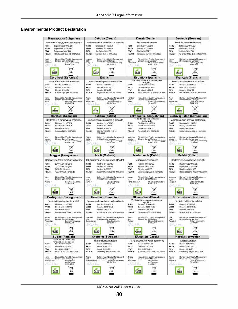
Appendix B Legal Information
MGS3750-28F User’s Guide
80
Environmental Product Declaration
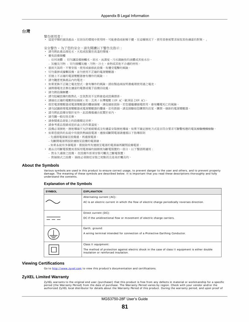
Appendix B Legal Information
MGS3750-28F User’s Guide
81
台灣警告使用者: • 這是甲類的資訊產品,在居住的環境中使用時,可能會造成射頻干擾,在這種情況下,使用者會被要求採取某些適當的對策。」
安全警告 - 為了您的安全,請先閱讀以下警告及指示 :• 請勿將此產品接近水、火焰或放置在高溫的環境。
• 避免設備接觸
- 任何液體 - 切勿讓設備接觸水、雨水、高濕度、污水腐蝕性的液體或其他水份。
- 灰塵及污物 - 切勿接觸灰塵、污物、沙土、食物或其他不合適的材料。
• 雷雨天氣時,不要安裝,使用或維修此設備。有遭受電擊的風險。
• 切勿重摔或撞擊設備,並勿使用不正確的電源變壓器。
• 若接上不正確的電源變壓器會有爆炸的風險。。
• 請勿隨意更換產品內的電池。
• 如果更換不正確之電池型式,會有爆炸的風險,請依製造商說明書處理使用過之電池。
• 請將廢電池丟棄在適當的電器或電子設備回收處。
• 請勿將設備解體。
• 請勿阻礙設備的散熱孔,空氣對流不足將會造成設備損害。
• 請插在正確的電壓供給插座 (如 : 北美 / 台灣電壓 110V AC,歐洲是 230V AC)。
• 假若電源變壓器或電源變壓器的纜線損壞,請從插座拔除,若您還繼續插電使用,會有觸電死亡的風險。
• 請勿試圖修理電源變壓器或電源變壓器的纜線,若有毀損,請直接聯絡您購買的店家,購買一個新的電源變壓器。
• 請勿將此設備安裝於室外,此設備僅適合放置於室內。
• 請勿隨一般垃圾丟棄。
• 請參閱產品背貼上的設備額定功率。
• 請參考產品型錄或是彩盒上的作業溫度。
• 設備必須接地,接地導線不允許被破壞或沒有適當安裝接地導線,如果不確定接地方式是否符合要求可聯繫相應的電氣檢驗機構檢驗。
• 如果您提供的系統中有提供熱插拔電源,連接或斷開電源請遵循以下指導原則
-先連接電源線至設備連,再連接電源。
-先斷開電源再拔除連接至設備的電源線。
-如果系統有多個電源,需拔除所有連接至電源的電源線再關閉設備電源。
• 產品沒有斷電裝置或者採用電源線的插頭視為斷電裝置的一部分,以下警語將適用 :
- 對永久連接之設備, 在設備外部須安裝可觸及之斷電裝置;
- 對插接式之設備, 插座必須接近安裝之地點而且是易於觸及的。
About the SymbolsVarious symbols are used in this product to ensure correct usage, to prevent danger to the user and others, and to prevent property damage. The meaning of these symbols are described below. It is important that you read these descriptions thoroughly and fully understand the contents.
Explanation of the Symbols
Viewing CertificationsGo to http://www.zyxel.com to view this product’s documentation and certifications.
ZyXEL Limited WarrantyZyXEL warrants to the original end user (purchaser) that this product is free from any defects in material or workmanship for a specific period (the Warranty Period) from the date of purchase. The Warranty Period varies by region. Check with your vendor and/or the authorized ZyXEL local distributor for details about the Warranty Period of this product. During the warranty period, and upon proof of
SYMBOL EXPLANATION
Alternating current (AC):
AC is an electric current in which the flow of electric charge periodically reverses direction.
Direct current (DC):
DC if the unidirectional flow or movement of electric charge carriers.
Earth; ground:
A wiring terminal intended for connection of a Protective Earthing Conductor.
Class II equipment:
The method of protection against electric shock in the case of class II equipment is either double insulation or reinforced insulation.
Appendix B Legal Information
MGS3750-28F User’s Guide
82
purchase, should the product have indications of failure due to faulty workmanship and/or materials, ZyXEL will, at its discretion, repair or replace the defective products or components without charge for either parts or labor, and to whatever extent it shall deem necessary to restore the product or components to proper operating condition. Any replacement will consist of a new or re-manufactured functionally equivalent product of equal or higher value, and will be solely at the discretion of ZyXEL. This warranty shall not apply if the product has been modified, misused, tampered with, damaged by an act of God, or subjected to abnormal working conditions.
NoteRepair or replacement, as provided under this warranty, is the exclusive remedy of the purchaser. This warranty is in lieu of all other warranties, express or implied, including any implied warranty of merchantability or fitness for a particular use or purpose. ZyXEL shall in no event be held liable for indirect or consequential damages of any kind to the purchaser.To obtain the services of this warranty, contact your vendor. You may also refer to the warranty policy for the region in which you bought the device at http://www.zyxel.com/web/support_warranty_info.php.
RegistrationRegister your product online to receive e-mail notices of firmware upgrades and information at www.zyxel.com for global products, or at www.us.zyxel.com for North American products.
TrademarksZyNOS (ZyXEL Network Operating System) and ZON (ZyXEL One Network)are registered trademarks of ZyXEL Communications, Inc. Other trademarks mentioned in this publication are used for identification purposes only and may be properties of their respective owners.
Open Source Licenses This product contains in part some free software distributed under GPL license terms and/or GPL like licenses. Open source licenses are provided with the firmware package. You can download the latest firmware at www.zyxel.com. To obtain the source code covered under those Licenses, please contact [email protected] to get it.
Related Documents


![Formless: A User's Guide, [excerpt] A User's Guide to Entropy ...](https://static.cupdf.com/doc/110x72/586b77ce1a28ab9c7d8bebd4/formless-a-users-guide-excerpt-a-users-guide-to-entropy-.jpg)