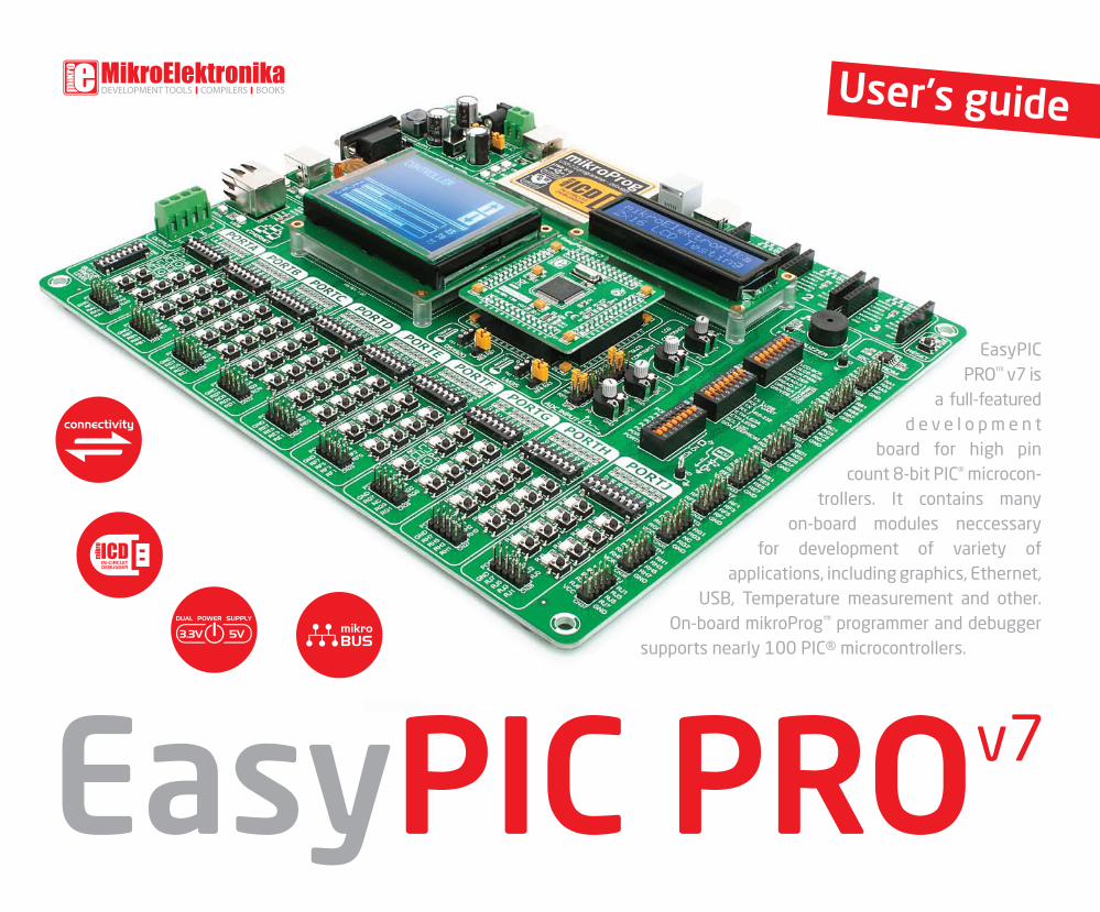
User's guide EasyPIC PRO ™ v7 is a full-featured development board for high pin count 8-bit PIC ® microcon- trollers. It contains many on-board modules neccessary for development of variety of applications, including graphics, Ethernet, USB, Temperature measurement and other. On-board mikroProg ™ programmer and debugger supports nearly 100 PIC® microcontrollers. EasyPIC PRO v7

Welcome message from author
This document is posted to help you gain knowledge. Please leave a comment to let me know what you think about it! Share it to your friends and learn new things together.
Transcript
User's guide
EasyPIC PRO™ v7 is
a full-featured d e v e l o p m e n t
board for high pin count 8-bit PIC® microcon-
trollers. It contains many on-board modules neccessary
for development of variety of applications, including graphics, Ethernet,
USB, Tempera ture measurement and other. On-board mikroProg™ programmer and debugger
supports nearly 100 PIC® microcontrollers.
EasyPIC PROv7

From the day one, we in mikroElektronika gave ourselves the highest possible goals in pursuit of excellence.
That same day, the idea of EasyPIC™ development board was born. And we all grew together with EasyPIC™.
In its each and tiniest piece we had put all of our energy, creativity and sense of what’s best for an engineer.
I’ve personally assembled hundreds of early EasyPIC™ boards myself with my home soldering iron.
EasyPIC PRO™ follows the same path. With the new 7th generation of high pin count PIC® boards it emerged
as a unified and clear concept, supporting both 5V and 3.3V microcontrollers. Now we proudly say that it's
one of a kind in the world - good looking, powerful and easy to use.
You made the right choice. But the fun has only just begun!
To our valued customers
Nebojsa Matic,
Owner and General Manager
of mikroElektronika
Tabl
e of
con
tent
s
page 3
Piezo Buzzer . . . . . . . . . . . . . . . . . . . . . . . . . . . . . . . . . . . . . .
LCD 2x16 characters . . . . . . . . . . . . . . . . . . . . . . . . . . . . . .
Introduction . . . . . . . . . . . . . . . . . . . . . . . . . . . . . . . . . . . . . . .
What’s Next? . . . . . . . . . . . . . . . . . . . . . . . . . . . . . . . . . . . . . .
ADC inputs . . . . . . . . . . . . . . . . . . . . . . . . . . . . . . . . . . . . . . . .
mikroBUS™ sockets . . . . . . . . . . . . . . . . . . . . . . . . . . . . . . .
Click Boards™ are plug and play . . . . . . . . . . . . . . . . . . . .
Installing programmer drivers . . . . . . . . . . . . . . . . . . . . . .
DS1820 - Digital Temperature Sensor . . . . . . . . . . . . . .
GLCD 128x64px . . . . . . . . . . . . . . . . . . . . . . . . . . . . . . . . . .
It's good to know . . . . . . . . . . . . . . . . . . . . . . . . . . . . . . . . . .
I2C EEPROM . . . . . . . . . . . . . . . . . . . . . . . . . . . . . . . . . . . . . . .
Input/Output Group . . . . . . . . . . . . . . . . . . . . . . . . . . . . . . .
Programming software . . . . . . . . . . . . . . . . . . . . . . . . . . . .
LM35 - Analog Temperature Sensor . . . . . . . . . . . . . . . .
On-board programmer . . . . . . . . . . . . . . . . . . . . . . . . . . . . .
Dual power supply . . . . . . . . . . . . . . . . . . . . . . . . . . . . . . . .
Supported microcontrollers . . . . . . . . . . . . . . . . . . . . . . . .
Touchpanel controller . . . . . . . . . . . . . . . . . . . . . . . . . . . . .
Output voltages . . . . . . . . . . . . . . . . . . . . . . . . . . . . . . . . . . .
Additional GNDs . . . . . . . . . . . . . . . . . . . . . . . . . . . . . . . . . . .
Introduction
Power Supply
Default MCU card
Programmer/debugger
Displays
Other modules
Connectivity
29
26
04
36
32
18
14
30
27
05
33
20
21
15
mikroICD™ - In Circuit Debugger . . . . . . . . . . . . . . . . . . . 16 31
12
06
08
28
34
35
UART via RS-232 . . . . . . . . . . . . . . . . . . . . . . . . . . . . . . . . .
UART via USB . . . . . . . . . . . . . . . . . . . . . . . . . . . . . . . . . . . . .
USB device communication . . . . . . . . . . . . . . . . . . . . . . . .
Ethernet communication . . . . . . . . . . . . . . . . . . . . . . . . . .
Communication22
23
24
25
Introductionin
tror
ucti
on
page 4
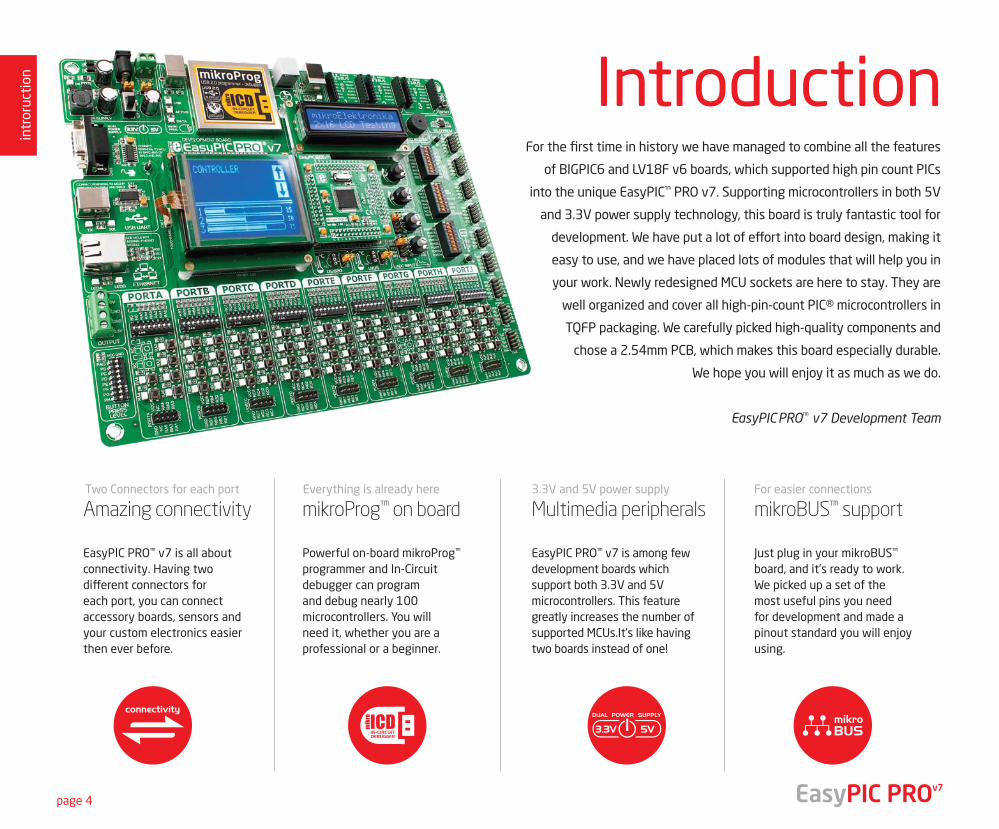
For the first time in history we have managed to combine all the features
of BIGPIC6 and LV18F v6 boards, which supported high pin count PICs
into the unique EasyPIC™ PRO v7. Supporting microcontrollers in both 5V
and 3.3V power supply technology, this board is truly fantastic tool for
development. We have put a lot of effort into board design, making it
easy to use, and we have placed lots of modules that will help you in
your work. Newly redesigned MCU sockets are here to stay. They are
well organized and cover all high-pin-count PIC® microcontrollers in
TQFP packaging. We carefully picked high-quality components and
chose a 2.54mm PCB, which makes this board especially durable.
We hope you will enjoy it as much as we do.
EasyPIC PRO™ v7 Development Team
EasyPIC PRO™ v7 is all about connectivity. Having two different connectors for each port, you can connect accessory boards, sensors and your custom electronics easier then ever before.
Powerful on-board mikroProg™ programmer and In-Circuit debugger can program and debug nearly 100 microcontrollers. You will need it, whether you are a professional or a beginner.
Two Connectors for each port Everything is already here
Amazing connectivity mikroProg™ on board
EasyPIC PRO™ v7 is among few development boards which support both 3.3V and 5V microcontrollers. This feature greatly increases the number of supported MCUs.It’s like having two boards instead of one!
3.3V and 5V power supply
Multimedia peripherals
Just plug in your mikroBUS™ board, and it’s ready to work. We picked up a set of the most useful pins you need for development and made a pinout standard you will enjoy using.
For easier connections
mikroBUS™ support
EasyPIC PROv7
19122011 www.mikroe.com
Copyright ©2011 Mikroelektronika. All rights reserved. Mikroelektronika, Mikroelektronika logo and other
Mikroelektronika trademarks are the property of Mikroelektronika. All other tradmarks are the property of their respective owners.
Unauthorised copying, hiring, renting, public performance and broadcasting of this DVD prohibited.
It's good to know
Package contains
intr
oduc
tion
page 5
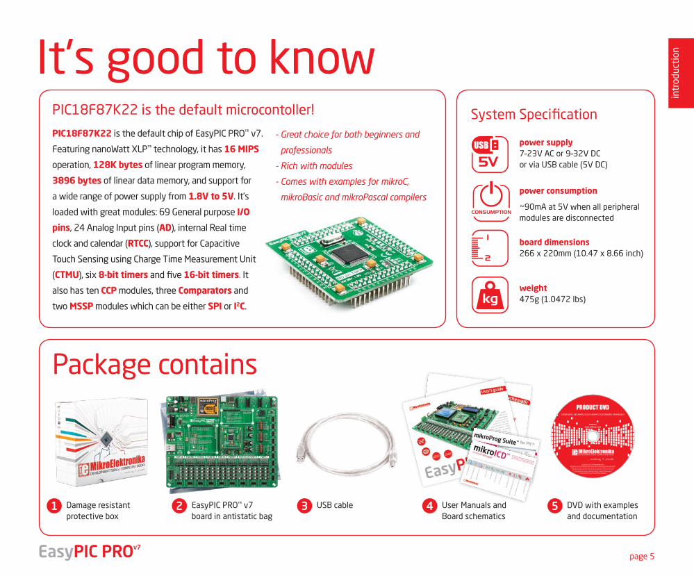
System SpecificationPIC18F87K22 is the default microcontoller!
power supply7–23V AC or 9–32V DC or via USB cable (5V DC)
board dimensions266 x 220mm (10.47 x 8.66 inch)
weight475g (1.0472 lbs)
power consumption
~90mA at 5V when all peripheral modules are disconnected
Damage resistant protective box
EasyPIC PRO™ v7 board in antistatic bag
USB cable User Manuals and Board schematics
DVD with examples and documentation
1 2 3 4 5
PIC18F87K22 is the default chip of EasyPIC PRO™ v7.
Featuring nanoWatt XLP™ technology, it has 16 MIPS
operation, 128K bytes of linear program memory,
3896 bytes of linear data memory, and support for
a wide range of power supply from 1.8V to 5V. It’s
loaded with great modules: 69 General purpose I/O
pins, 24 Analog Input pins (AD), internal Real time
clock and calendar (RTCC), support for Capacitive
Touch Sensing using Charge Time Measurement Unit
(CTMU), six 8-bit timers and five 16-bit timers. It
also has ten CCP modules, three Comparators and
two MSSP modules which can be either SPI or I2C.
- Great choice for both beginners and
professionals
- Rich with modules
- Comes with examples for mikroC,
mikroBasic and mikroPascal compilers
EasyPIC PROv7
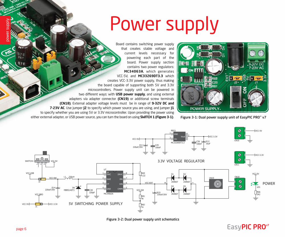
Power supplyBoard contains switching power supply
that creates stable voltage and current levels necessary for
powering each part of the board. Power supply section contains two power regulators:
MC34063A, which generates VCC-5V, and MC33269DT3.3 which
creates VCC-3.3V power supply, thus making the board capable of supporting both 5V and 3.3V
microcontrollers. Power supply unit can be powered in two different ways: with USB power supply, and using external
adapters via adapter connector (CN19) or additional screw terminals (CN18). External adapter voltage levels must be in range of 9-32V DC and
7-23V AC. Use jumper J2 to specify which power source you are using, and jumper J1 to specify whether you are using 5V or 3.3V microcontroller. Upon providing the power using
either external adapter, or USB power source, you can turn the board on using SWITCH 1 (Figure 3-1).
Figure 3-2: Dual power supply unit schematics
Figure 3-1: Dual power supply unit of EasyPIC PRO™ v7
pow
er s
uppl
y
page 6 EasyPIC PROv7
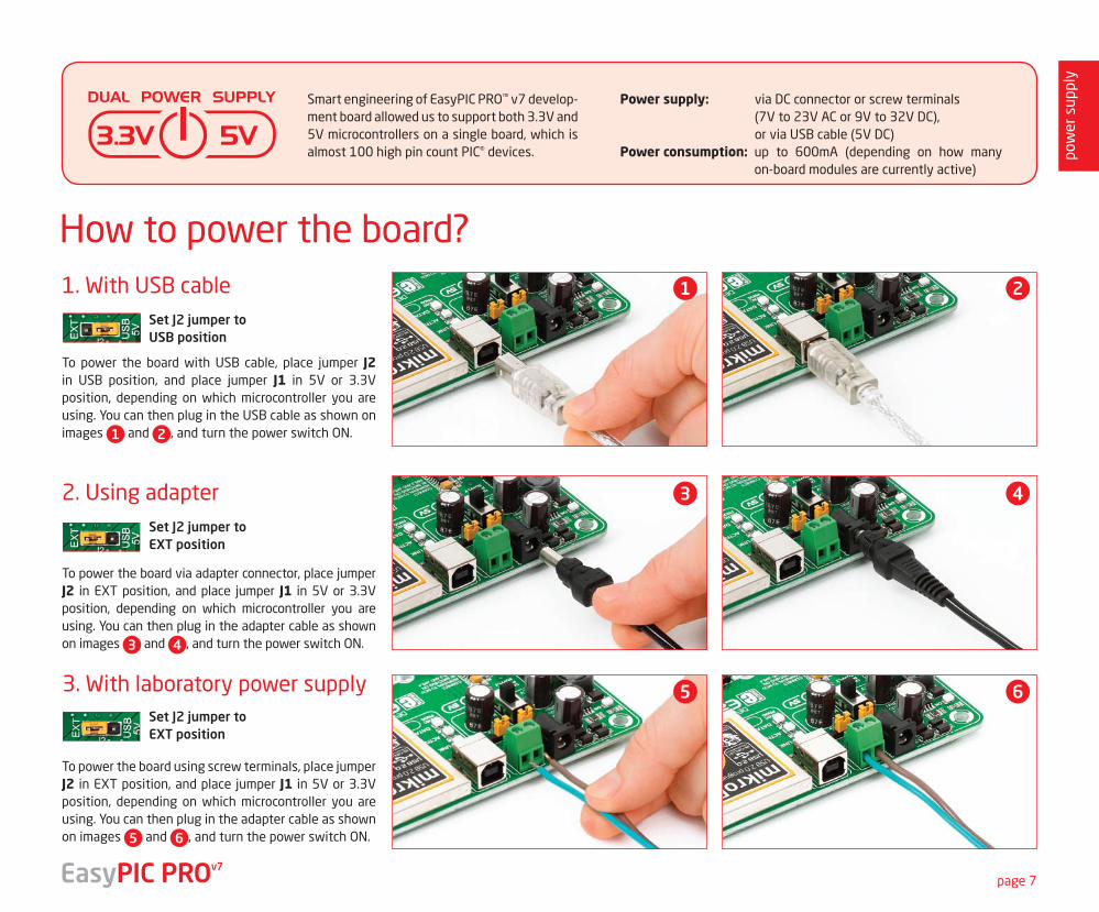
How to power the board?
To power the board with USB cable, place jumper J2 in USB position, and place jumper J1 in 5V or 3.3V position, depending on which microcontroller you are using. You can then plug in the USB cable as shown on images 1 and 2 , and turn the power switch ON.
To power the board via adapter connector, place jumper J2 in EXT position, and place jumper J1 in 5V or 3.3V position, depending on which microcontroller you are using. You can then plug in the adapter cable as shown on images 3 and 4 , and turn the power switch ON.
To power the board using screw terminals, place jumper J2 in EXT position, and place jumper J1 in 5V or 3.3V position, depending on which microcontroller you are using. You can then plug in the adapter cable as shown on images 5 and 6 , and turn the power switch ON.
Smart engineering of EasyPIC PRO™ v7 develop-ment board allowed us to support both 3.3V and 5V microcontrollers on a single board, which is almost 100 high pin count PIC® devices.
Power supply: via DC connector or screw terminals (7V to 23V AC or 9V to 32V DC), or via USB cable (5V DC)
Power consumption: up to 600mA (depending on how many on-board modules are currently active)
Set J2 jumper to USB position
1. With USB cable
3. With laboratory power supply
Set J2 jumper to EXT position
Set J2 jumper to EXT position
2. Using adapter
1
3
5
2
4
6
pow
er s
uppl
y
page 7EasyPIC PROv7
supp
orte
d M
CUs
page 8
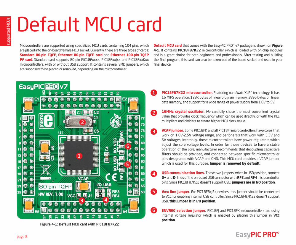
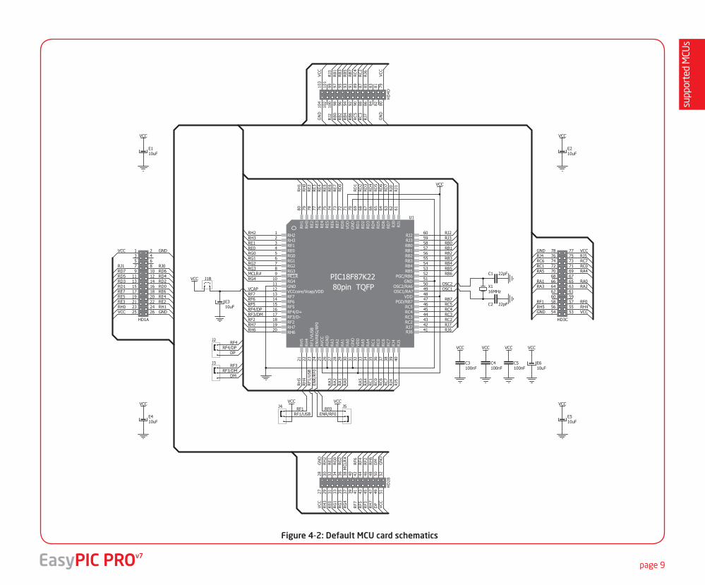
Default MCU cardMicrocontrollers are supported using specialized MCU cards containing 104 pins, which are placed into the on-board female MCU socket. Currently, there are three types of cards: Standard 80-pin TQFP, Ethernet 80-pin TQFP card and Ethernet 100-pin TQFP PF card. Standard card supports 80-pin PIC18Fxxxx, PIC18FxxJxx and PIC18FxxKxx microcontrollers, with or without USB support. It contains several SMD jumpers, which are supposed to be placed or removed, depending on the microcontroller.
Default MCU card that comes with the EasyPIC PRO™ v7 package is shown on Figure 4-1. It contains PIC18F87K22 microcontroller which is loaded with on-chip modules and is a great choice for both beginners and professionals. After testing and building the final program, this card can also be taken out of the board socket and used in your final device.
PIC18F87K22 microcontroller. Featuring nanoWatt XLP™ technology, it has 16 MIPS operation, 128K bytes of linear program memory, 3896 bytes of linear data memory, and support for a wide range of power supply from 1.8V to 5V.
16MHz crystal oscillator. We carefully chose the most convenient crystal value that provides clock frequency which can be used directly, or with the PLL multipliers and dividers to create higher MCU clock value.
VCAP jumper. Some PIC18FK and all PIC18FJ microcontrollers have cores that work on 1.8V-2.5V voltage range, and peripherals that work with 3.3V and 5V voltages. Internally, those microcontrollers have power regulators which adjust the core voltage levels. In order for those devices to have a stable operation of the core, manufacturer recommends that decoupling capacitive filters should be provided, and connected between specific microcontroller pins designated with VCAP and GND. This MCU card provides a VCAP jumper which is used for this purpose. Jumper is removed by default.
USB communication lines. These two jumpers, when in USB position, connect D+ and D- lines of the on-board USB connector with RF3 and RF4 microcontroller pins. Since PIC18F87K22 doesn't support USB, jumpers are in I/O position.
VUSB line jumper. For PIC18F8xJ5x devices, this jumper should be connected to VCC for enabling internal USB controller. Since PIC18F87K22 doesn't support USB, this jumper is in I/O position.
ENVREG selection jumper. PIC18FJ and PIC18FK microcontrollers are using internal voltage regulator which is enabled by placing this jumper in VCC position.
EasyPIC PROv7
2
3 4
5
6
1
1
2
3
4
5
6
Figure 4-1: Default MCU card with PIC18F87K22
supp
orte
d M
CUs
page 9EasyPIC PROv7
RH2RH3
RE0RE1
RG0RG1RG2RG3
RG4MCLR#
VCAP
RF2RF3/DMRF4/DPRF5RF6RF7
RH7
RH
4R
H5
RH6
RF1
/USB
ENR
/RF0
RA
0R
A1
RA
2R
A3
RA
4R
A5
RC
0R
C1
RC
6R
C7
RJ4
RJ5
RJ6RJ7RC2RC3RC4RC5
RB0RB1RB2RB3RB4RB5RB6
RB7
OSC1OSC2
RJ0
RJ1
RJ2RJ3
RD
0
RD
1R
D2
RD
3R
D4
RD
5R
D6
RD
7
RH
0R
H1
RE2
RE3
RE4
RE5
RE6
RE7
30292827 3433
58575655545352
47
3635
43444546
37 38
9
495011
12
32
72 69 68 67 66 65 64 63
43
78 772423
181716151413
5678
10
7980
12
2221
2019
62 61
6059
39 40
4142
48
7131
51
70
262576 75 74 73
GNDGND
GN
DG
ND
VDD
VDD
RB0RB1RB2RB3RB4RB5
PGC/RB6
PGD/RB7
RC2RC3RC4RC5
VDD
OSC2/RA6OSC1/RA7
RJ2RJ3
RJ6RJ7
RD
0
RD
1R
D2
RD
3R
D4
RD
5R
D6
RD
7
RE2
RE3
RE4
RE5
RE6
RE7
RH
0R
H1
RJ0
RJ1
RE0RE1
RH2RH3
RG0RG1RG2RG3
RG4MCLR
RF2RF3/D-RF4/D+RF5RF6RF7
RH6RH7
VCCcore/Vcap/VDD
RA
0R
A1
RA
2R
A3
RA
4R
A5
RC
0R
C1
RC
6R
C7
RJ4
RJ5
RH
4R
H5
RF1
/VU
SBEN
VREG
/RF0
AVC
CA
GN
D
PIC18F87K2280pin TQFP
U1
E310uF
VCC
VCC
X116MHz
C1 22pF
C2 22pF
C3100nF
VCC
C4100nF
VCC
C5100nF
VCC
E610uF
VCC
E410uF
VCC
E510uF
VCC
E110uF
VCC
E210uF
VCC
VCC
RF0RF1
VCC
RF3/DM
RF4/DP
RF3
RF4
DM
DP
RH
2R
H3
RE0
RE1
RG
0R
G1
RG
2R
G3
RG
4M
CLR
#
RF2
RF3
RF4
RF5
RF6
RF7
RH
7R
H6
DP
DM
VCC
GN
D
VCC
GN
D
VCC GND
VCC GND
VCC
GN
D
VCC
GN
D
VCCGND
VCCGND
RJ0RJ1
RD0RD1RD2RD3RD4RD5RD6RD7
RH0 RH1RE2RE3RE4RE5RE6RE7
RB0
RB1
RB2
RB3
RB4
RB5
RB6
RJ2
RJ3
RJ6
RJ7
RC
2R
C3
RC
4R
C5
RB7
RH4RH5
RA0RA1RA2RA3
RA4RA5RC0RC1
RC6 RC7RJ4 RJ5
RF0RF1
1 23 45 67 89 10
11 1213 1415 1617 1819 2021 2223 2425 26
HD1A27
2829
3031
3233
3435
3637
3839
4041
4243
4445
4647
4849
5051
52
HD
2B
5354555657585960616263646566676869707172737475767778
HD3C
7980
8182
8384
8586
8788
8990
9192
9394
9596
9798
9910
010
110
210
310
4
HD
4D
J2
J3
J4 J5
RF1/USB ENR/RF0
J1B
Figure 4-2: Default MCU card schematics
supp
orte
d M
CUs
page 10 EasyPIC PROv7
1 2 3
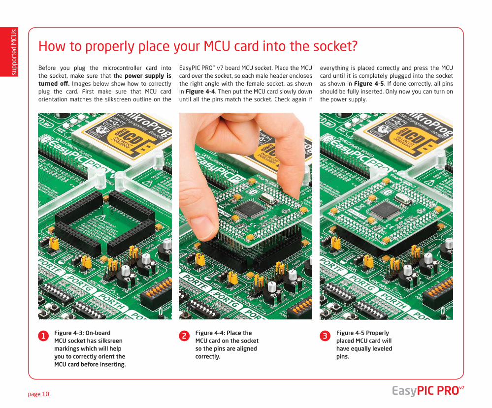
How to properly place your MCU card into the socket?Before you plug the microcontroller card into the socket, make sure that the power supply is turned off. Images below show how to correctly plug the card. First make sure that MCU card orientation matches the silkscreen outline on the
EasyPIC PRO™ v7 board MCU socket. Place the MCU card over the socket, so each male header encloses the right angle with the female socket, as shown in Figure 4-4. Then put the MCU card slowly down until all the pins match the socket. Check again if
everything is placed correctly and press the MCU card until it is completely plugged into the socket as shown in Figure 4-5. If done correctly, all pins should be fully inserted. Only now you can turn on the power supply.
Figure 4-3: On-board MCU socket has silksreen markings which will help you to correctly orient the MCU card before inserting.
Figure 4-4: Place the MCU card on the socket so the pins are aligned correctly.
Figure 4-5 Properly placed MCU card will have equally leveled pins.
supp
orte
d M
CUs
page 11
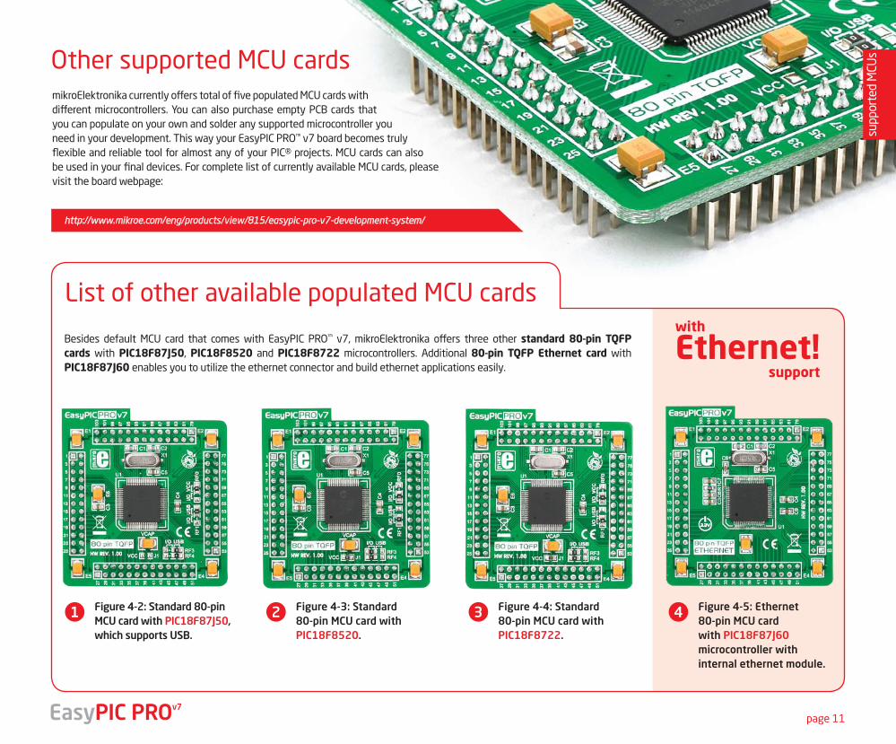
mikroElektronika currently offers total of five populated MCU cards with different microcontrollers. You can also purchase empty PCB cards that you can populate on your own and solder any supported microcontroller you need in your development. This way your EasyPIC PRO™ v7 board becomes truly flexible and reliable tool for almost any of your PIC® projects. MCU cards can also be used in your final devices. For complete list of currently available MCU cards, please visit the board webpage:
Other supported MCU cards
List of other available populated MCU cards
EasyPIC PROv7
1 2 3 4Figure 4-2: Standard 80-pin MCU card with PIC18F87J50, which supports USB.
Figure 4-3: Standard 80-pin MCU card with PIC18F8520.
Figure 4-4: Standard 80-pin MCU card with PIC18F8722.
Figure 4-5: Ethernet 80-pin MCU card with PIC18F87J60 microcontroller with internal ethernet module.
Besides default MCU card that comes with EasyPIC PRO™ v7, mikroElektronika offers three other standard 80-pin TQFP cards with PIC18F87J50, PIC18F8520 and PIC18F8722 microcontrollers. Additional 80-pin TQFP Ethernet card with PIC18F87J60 enables you to utilize the ethernet connector and build ethernet applications easily. support
with
Ethernet!
http://www.mikroe.com/eng/products/view/815/easypic-pro-v7-development-system/
prog
ram
min
g
page 12
On-board programmer
What is mikroProg™?
How do I start?
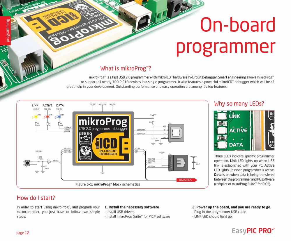
mikroProg™ is a fast USB 2.0 programmer with mikroICD™ hardware In-Circuit Debugger. Smart engineering allows mikroProg™ to support all nearly 100 PIC18 devices in a single programmer. It also features a powerful mikroICD™ debugger which will be of
great help in your development. Outstanding performance and easy operation are among it's top features.
In order to start using mikroProg™, and program your microcontroller, you just have to follow two simple steps:
1. Install the necessary software- Install USB drivers- Install mikroProg Suite™ for PIC® software
2. Power up the board, and you are ready to go.- Plug in the programmer USB cable- LINK LED should light up.
DATA BUS
Figure 5-1: mikroProg™ block schematics
EasyPIC PROv7
Why so many LEDs?
Three LEDs indicate specific programmer operation. Link LED lights up when USB link is established with your PC, Active LED lights up when programmer is active. Data is on when data is being transfered between the programmer and PC software (compiler or mikroProg Suite™ for PIC®).
prog
ram
min
g
page 13
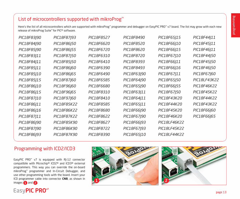
List of microcontrollers supported with mikroProg™
Here's the list of all microcontrollers which are supported with mikroProg™ programmer and debugger on EasyPIC PRO™ v7 board. The list may grow with each new release of mikroProg Suite™ for PIC® software.
EasyPIC PRO™ v7 is equipped with RJ-12 connector compatibile with Microchip® ICD2® and ICD3® external programmers. This way you can override the on-board mikroProg™ programmer and In-Circuit Debugger, and use other programming tools with the board. Insert your ICD programmer cable into connector CN8, as shown in images 1 and 2 . 1 2
Programming with ICD2/ICD3
EasyPIC PROv7
PIC18F83J90
PIC18F84J90
PIC18F85J90
PIC18F83J11
PIC18F84J11
PIC18F85J11
PIC18F85J10
PIC18F85J15
PIC18F86J10
PIC18F86J15
PIC18F87J10
PIC18F86J11
PIC18F86J16
PIC18F87J11
PIC18F86J90
PIC18F87J90
PIC18F86J93
PIC18F87J93
PIC18F86J50
PIC18F86J55
PIC18F87J50
PIC18F85J50
PIC18F86J60
PIC18F86J65
PIC18F87J60
PIC18F96J60
PIC18F96J65
PIC18F97J60
PIC18F85K22
PIC18F86K22
PIC18F87K22
PIC18F85K90
PIC18F86K90
PIC18F87K90
PIC18F8527
PIC18F6620
PIC18F6720
PIC18F6310
PIC18F6410
PIC18F6390
PIC18F6490
PIC18F6585
PIC18F6680
PIC18F8310
PIC18F8410
PIC18F8585
PIC18F8680
PIC18F8622
PIC18F8627
PIC18F8722
PIC18F8390
PIC18F8490
PIC18F8520
PIC18F8620
PIC18F8720
PIC18F8393
PIC18F8493
PIC18F63J90
PIC18F64J90
PIC18F65J90
PIC18F63J11
PIC18F64J11
PIC18F65J11
PIC18F66J90
PIC18F67J90
PIC18F66J93
PIC18F67J93
PIC18F65J10
PIC18F65J15
PIC18F66J10
PIC18F66J15
PIC18F67J10
PIC18F66J11
PIC18F66J16
PIC18F67J11
PIC18F65J50
PIC18F66J55
PIC18F67J50
PIC18F43K20
PIC18F44K20
PIC18F45K20
PIC18F46K20
PIC18LF46K22
PIC18LF45K22
PIC18LF44K22
PIC18F44J11
PIC18F45J11
PIC18F46J11
PIC18F44J50
PIC18F45J50
PIC18F46J50
PIC18F67J60
PIC18LF43K22
PIC18F46K22
PIC18F45K22
PIC18F44K22
PIC18F43K22
PIC18F66J60
PIC18F66J65
prog
ram
min
g
page 14
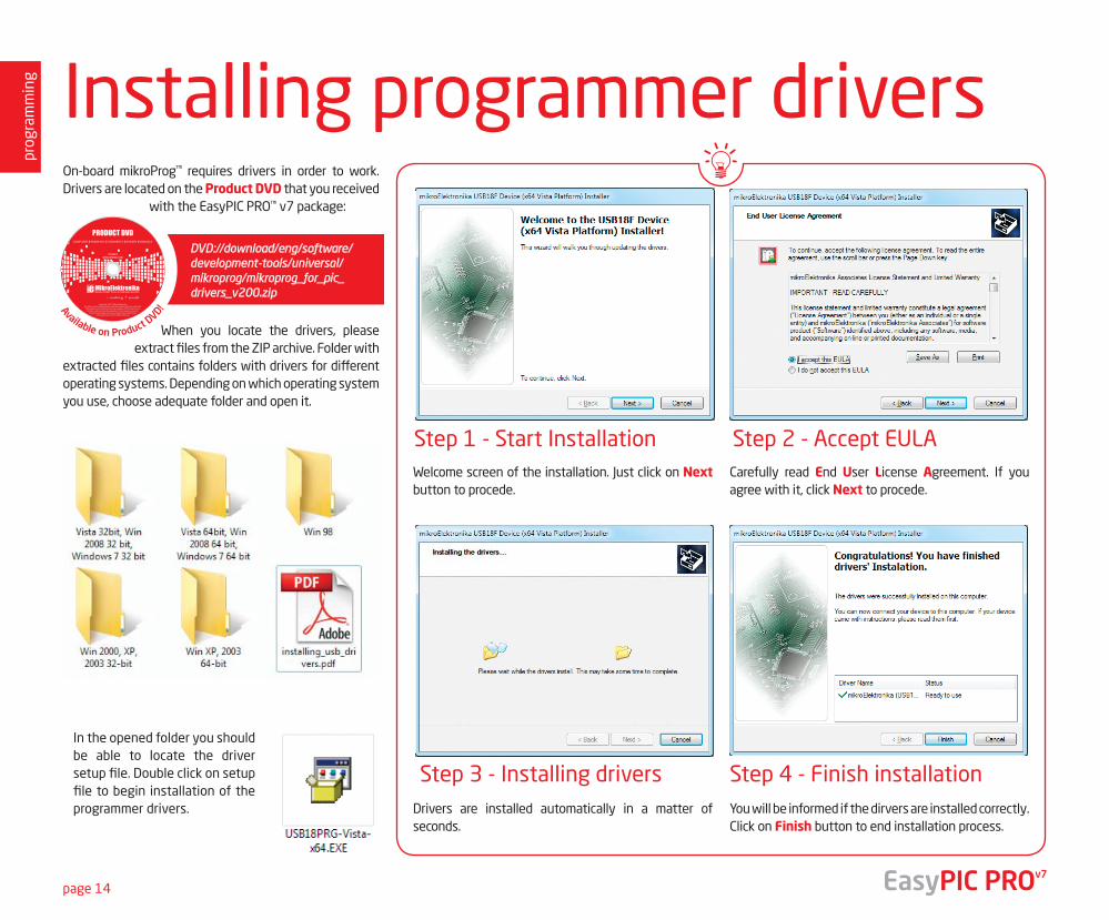
Step 1 - Start Installation
Step 3 - Installing drivers Step 4 - Finish installation
Step 2 - Accept EULA
On-board mikroProg™ requires drivers in order to work. Drivers are located on the Product DVD that you received
with the EasyPIC PRO™ v7 package:
When you locate the drivers, please extract files from the ZIP archive. Folder with
extracted files contains folders with drivers for different operating systems. Depending on which operating system you use, choose adequate folder and open it.
Installing programmer drivers
DVD://download/eng/software/development-tools/universal/ mikroprog/mikroprog_for_pic_ drivers_v200.zip
In the opened folder you should be able to locate the driver setup file. Double click on setup file to begin installation of the programmer drivers.
Welcome screen of the installation. Just click on Next button to procede.
Drivers are installed automatically in a matter of seconds.
You will be informed if the dirvers are installed correctly. Click on Finish button to end installation process.
Carefully read End User License Agreement. If you agree with it, click Next to procede.
EasyPIC PROv7
Available on Product DVD!
19122011 www.mikroe.com
Copyright ©2011 Mikroelektronika. All rights reserved. Mikroelektronika, Mikroelektronika logo and other
Mikroelektronika trademarks are the property of Mikroelektronika. All other tradmarks are the property of their respective owners.
Unauthorised copying, hiring, renting, public performance and broadcasting of this DVD prohibited.
prog
ram
min
g
page 15
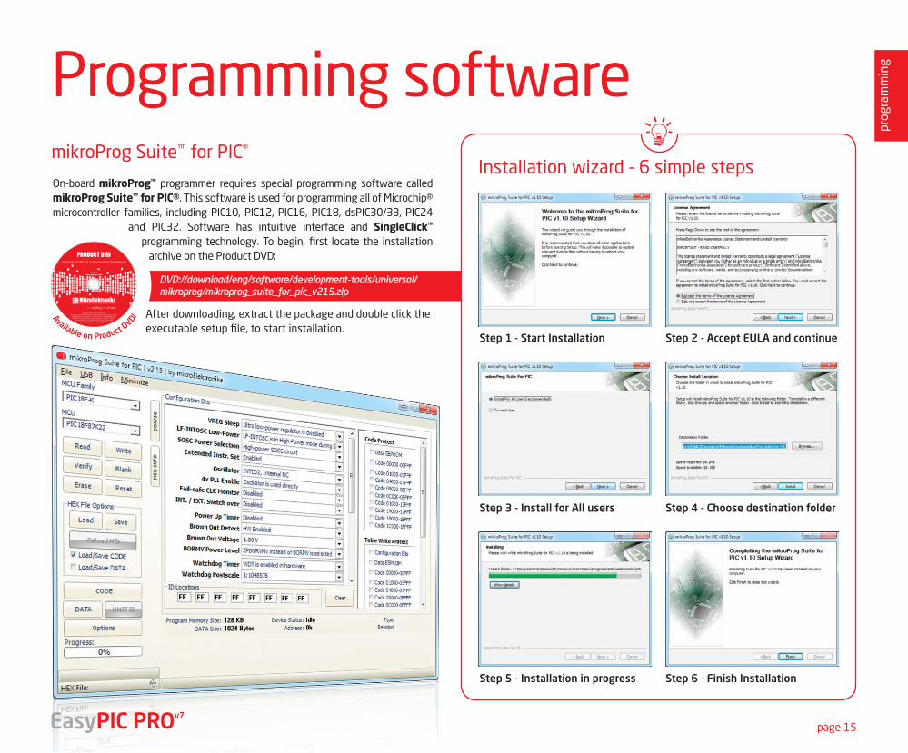
Step 1 - Start Installation
Step 3 - Install for All users
Step 5 - Installation in progress
Step 2 - Accept EULA and continue
Step 4 - Choose destination folder
Step 6 - Finish Installation
Programming softwaremikroProg Suite™ for PIC®
Installation wizard - 6 simple stepsOn-board mikroProg™ programmer requires special programming software called mikroProg Suite™ for PIC®. This software is used for programming all of Microchip® microcontroller families, including PIC10, PIC12, PIC16, PIC18, dsPIC30/33, PIC24
and PIC32. Software has intuitive interface and SingleClick™ programming technology. To begin, first locate the installation
archive on the Product DVD:
After downloading, extract the package and double click the executable setup file, to start installation.
DVD://download/eng/software/development-tools/universal/mikroprog/mikroprog_suite_for_pic_v215.zip
EasyPIC PROv7
Available on Product DVD!
19122011 www.mikroe.com
Copyright ©2011 Mikroelektronika. All rights reserved. Mikroelektronika, Mikroelektronika logo and other
Mikroelektronika trademarks are the property of Mikroelektronika. All other tradmarks are the property of their respective owners.
Unauthorised copying, hiring, renting, public performance and broadcasting of this DVD prohibited.
prog
ram
min
g
page 16
mikroICD™ - In Circuit DebuggerWhat is Debugging?Every developer comes to a point where he has to monitor the code execution in order to find errors in the code, or simply to see if everything is going as planed. This hunt for bugs, or errors in the code is called debugging. There are two ways to do this: one is the software simulation, which enables you to simulate what is supposed to be happening on the microcontroller as your code lines are executed, and the other, most reliable one, is monitoring the code execution on the chip itself. And this latter one is called In-Circuit debugging. "In-Circuit" means that it is the real deal - code executes right on the target device.
What is mikroICD™?
The on-board mikroProg™ programmer supports mikroICD™ - a highly effective tool for a Real-Time debugging on hardware level. The mikroICD™ debugger enables you to execute your program on the host PIC microcontroller and view variable values, Special Function Registers (SFR), RAM, CODE and EEPROM memory along with the mikroICD™ code execution on hardware. Whether you are a beginner, or a professional, this powerful tool, with intuitive interface and convenient set of commands will enable you to track down bugs quickly. mikroICD™ is one of the fastest, and most reliable debugging tools on the market.
Supported Compilers
All MikroElektronika compilers, mikroC, mikroBasic and mikroPascal for PIC®, dsPIC® and PIC32® natively support mikroICD™. Specialized mikroICD DLL module allows compilers to exploit the full potential of fast hardware debugging. Along with compilers, make sure to install the appropriate programmer drivers and mikroProg Suite for PIC® programming software, as described on pages 14 and 15.
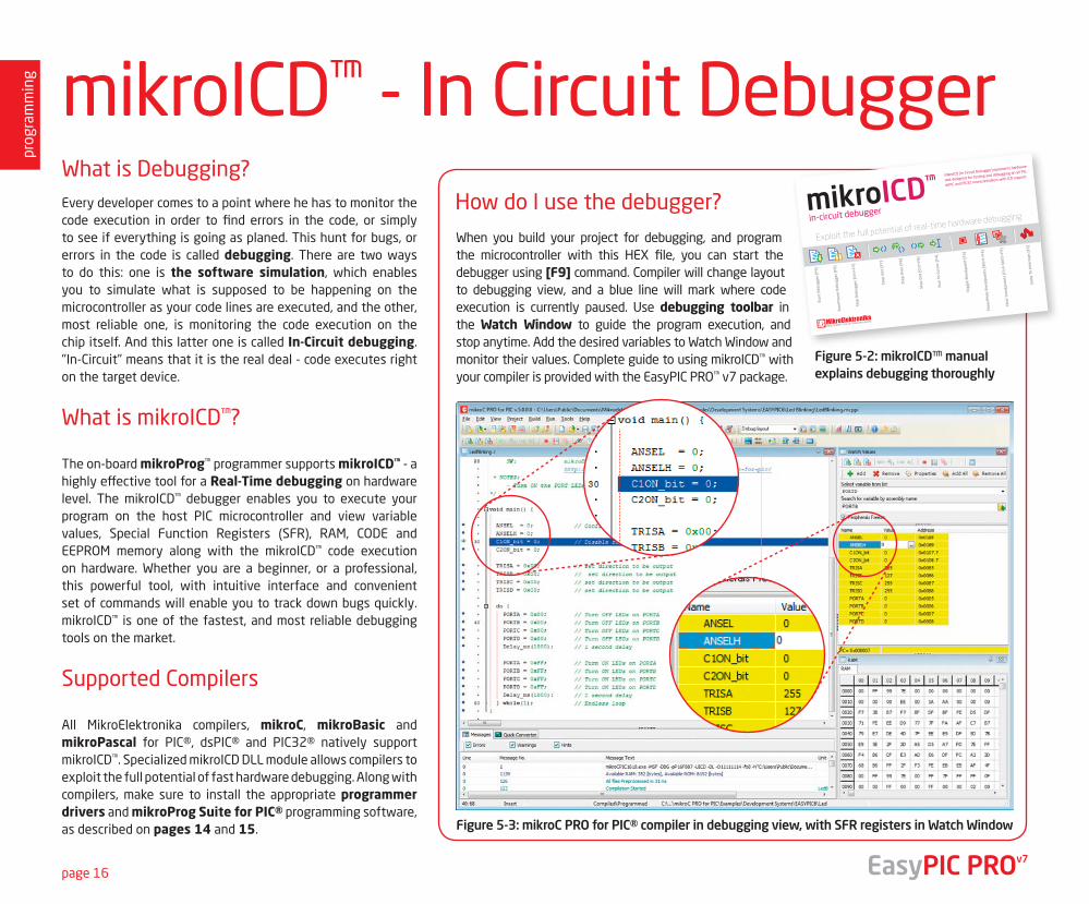
When you build your project for debugging, and program the microcontroller with this HEX file, you can start the debugger using [F9] command. Compiler will change layout to debugging view, and a blue line will mark where code execution is currently paused. Use debugging toolbar in the Watch Window to guide the program execution, and stop anytime. Add the desired variables to Watch Window and monitor their values. Complete guide to using mikroICD™ with your compiler is provided with the EasyPIC PRO™ v7 package.
How do I use the debugger?
Figure 5-3: mikroC PRO for PIC® compiler in debugging view, with SFR registers in Watch Window
Figure 5-2: mikroICD™ manual explains debugging thoroughly
mikroICD™
in-circuit debugger
EasyPIC PROv7
prog
ram
min
g
page 17
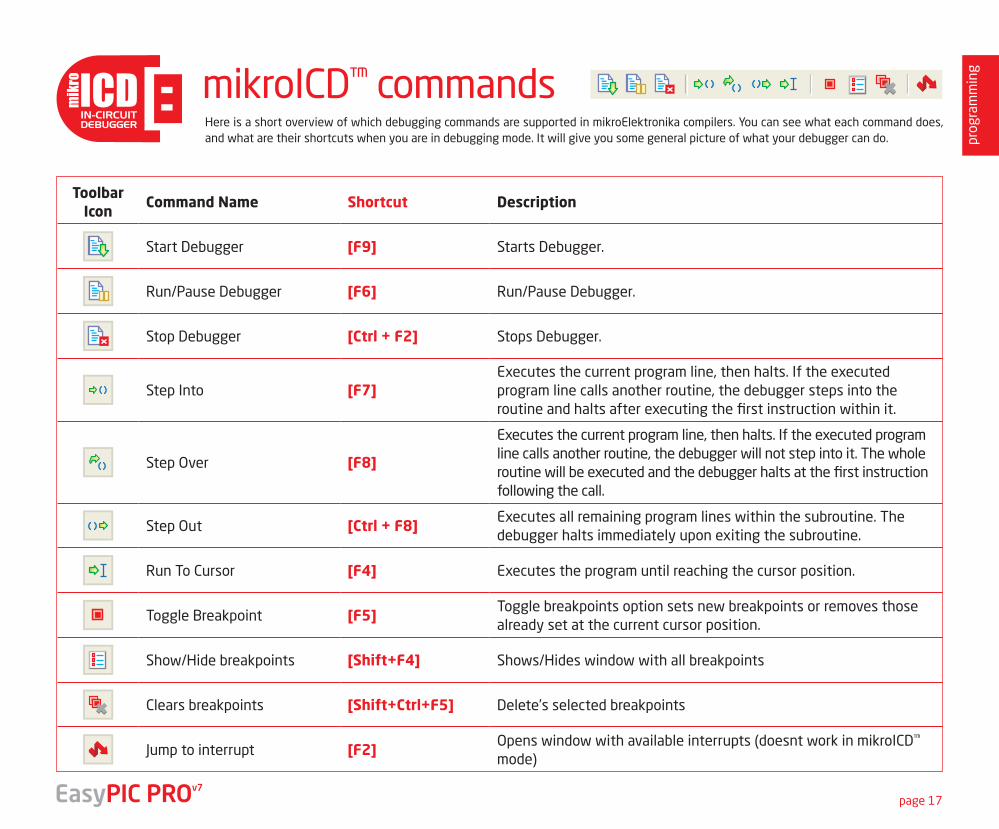
Here is a short overview of which debugging commands are supported in mikroElektronika compilers. You can see what each command does, and what are their shortcuts when you are in debugging mode. It will give you some general picture of what your debugger can do.
Toolbar Icon
Command Name Shortcut Description
Start Debugger [F9] Starts Debugger.
Run/Pause Debugger [F6] Run/Pause Debugger.
Stop Debugger [Ctrl + F2] Stops Debugger.
Step Into [F7]Executes the current program line, then halts. If the executed program line calls another routine, the debugger steps into the routine and halts after executing the first instruction within it.
Step Over [F8]
Executes the current program line, then halts. If the executed program line calls another routine, the debugger will not step into it. The whole routine will be executed and the debugger halts at the first instruction following the call.
Step Out [Ctrl + F8]Executes all remaining program lines within the subroutine. The debugger halts immediately upon exiting the subroutine.
Run To Cursor [F4] Executes the program until reaching the cursor position.
Toggle Breakpoint [F5]Toggle breakpoints option sets new breakpoints or removes those already set at the current cursor position.
Show/Hide breakpoints [Shift+F4] Shows/Hides window with all breakpoints
Clears breakpoints [Shift+Ctrl+F5] Delete’s selected breakpoints
Jump to interrupt [F2]Opens window with available interrupts (doesnt work in mikroICD™ mode)
mikroICD™ commands
EasyPIC PROv7
page 18
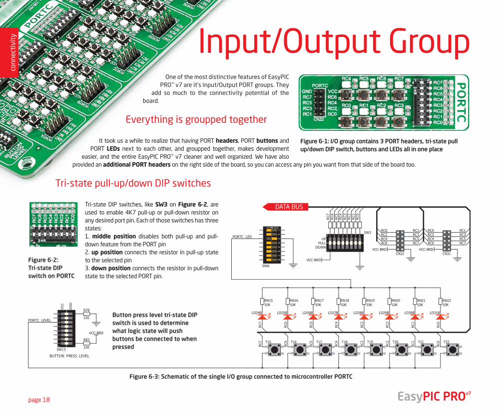
One of the most distinctive features of EasyPIC PRO™ v7 are it’s Input/Output PORT groups. They
add so much to the connectivity potential of the board.
Everything is groupped together
It took us a while to realize that having PORT headers, PORT buttons and PORT LEDs next to each other, and groupped together, makes development
easier, and the entire EasyPIC PRO™ v7 cleaner and well organized. We have also provided an additional PORT headers on the right side of the board, so you can access any pin you want from that side of the board too.
Tri-state pull-up/down DIP switches
Tri-state DIP switches, like SW3 on Figure 6-2, are used to enable 4K7 pull-up or pull-down resistor on any desired port pin. Each of those switches has three states:1. middle position disables both pull-up and pull-down feature from the PORT pin2. up position connects the resistor in pull-up state to the selected pin3. down position connects the resistor in pull-down state to the selected PORT pin.
Figure 6-1: I/O group contains 3 PORT headers, tri-state pull up/down DIP switch, buttons and LEDs all in one place
DATA BUS
Figure 6-3: Schematic of the single I/O group connected to microcontroller PORTC
Button press level tri-state DIP switch is used to determine what logic state will push buttons be connected to when pressed
Input/Output Group
Figure 6-2: Tri-state DIP switch on PORTC
conn
ecti
vity
EasyPIC PROv7
conn
ecti
vity
page 19
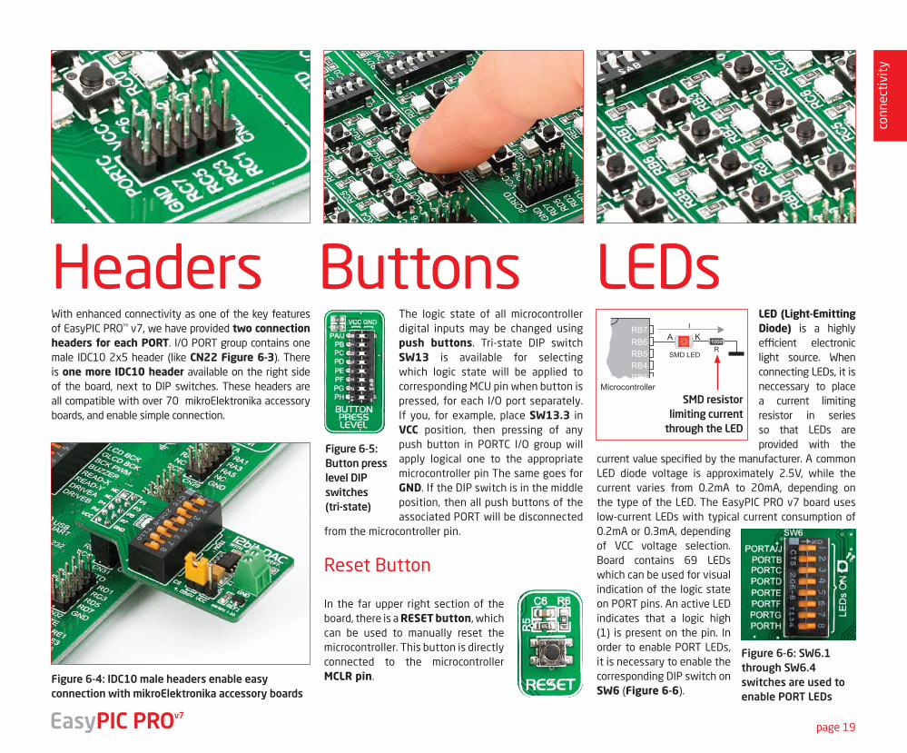
Headers Buttons LEDs
Figure 6-4: IDC10 male headers enable easy connection with mikroElektronika accessory boards
With enhanced connectivity as one of the key features of EasyPIC PRO™ v7, we have provided two connection headers for each PORT. I/O PORT group contains one male IDC10 2x5 header (like CN22 Figure 6-3). There is one more IDC10 header available on the right side of the board, next to DIP switches. These headers are all compatible with over 70 mikroElektronika accessory boards, and enable simple connection.
LED (Light-Emitting Diode) is a highly efficient electronic light source. When connecting LEDs, it is neccessary to place a current limiting resistor in series so that LEDs are provided with the
current value specified by the manufacturer. A common LED diode voltage is approximately 2.5V, while the current varies from 0.2mA to 20mA, depending on the type of the LED. The EasyPIC PRO v7 board uses low-current LEDs with typical current consumption of 0.2mA or 0.3mA, depending of VCC voltage selection. Board contains 69 LEDs which can be used for visual indication of the logic state on PORT pins. An active LED indicates that a logic high (1) is present on the pin. In order to enable PORT LEDs, it is necessary to enable the corresponding DIP switch on SW6 (Figure 6-6).
Figure 6-6: SW6.1 through SW6.4 switches are used to enable PORT LEDs
Microcontroller
The logic state of all microcontroller digital inputs may be changed using push buttons. Tri-state DIP switch SW13 is available for selecting which logic state will be applied to corresponding MCU pin when button is pressed, for each I/O port separately. If you, for example, place SW13.3 in VCC position, then pressing of any push button in PORTC I/O group will apply logical one to the appropriate microcontroller pin The same goes for GND. If the DIP switch is in the middle position, then all push buttons of the associated PORT will be disconnected
from the microcontroller pin.
Reset Button
In the far upper right section of the board, there is a RESET button, which can be used to manually reset the microcontroller. This button is directly connected to the microcontroller MCLR pin.
Figure 6-5: Button press level DIP switches (tri-state)
SMD resistor limiting current
through the LED
EasyPIC PROv7
DATA
BU
S
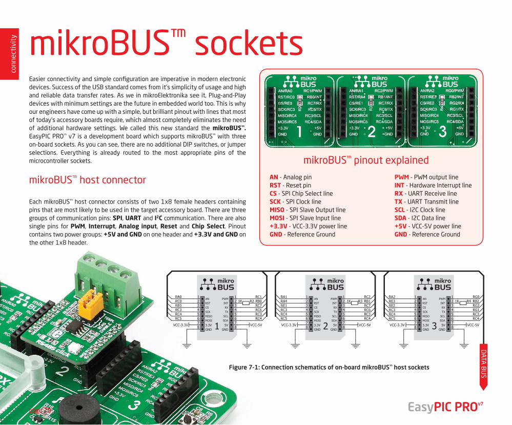
mikroBUS™ pinout explained
AN - Analog pinRST - Reset pinCS - SPI Chip Select lineSCK - SPI Clock lineMISO - SPI Slave Output lineMOSI - SPI Slave Input line+3.3V - VCC-3.3V power lineGND - Reference Ground
PWM - PWM output lineINT - Hardware Interrupt lineRX - UART Receive lineTX - UART Transmit lineSCL - I2C Clock lineSDA - I2C Data line+5V - VCC-5V power lineGND - Reference Ground
Figure 7-1: Connection schematics of on-board mikroBUS™ host sockets
conn
ecti
vity
EasyPIC PROv7
mikroBUS™ sockets
page 20
Easier connectivity and simple configuration are imperative in modern electronic devices. Success of the USB standard comes from it’s simplicity of usage and high and reliable data transfer rates. As we in mikroElektronika see it, Plug-and-Play devices with minimum settings are the future in embedded world too. This is why our engineers have come up with a simple, but brilliant pinout with lines that most of today’s accessory boards require, which almost completely eliminates the need of additional hardware settings. We called this new standard the mikroBUS™. EasyPIC PRO™ v7 is a development board which supports mikroBUS™ with three on-board sockets. As you can see, there are no additional DIP switches, or jumper selections. Everything is already routed to the most appropriate pins of the microcontroller sockets.
mikroBUS™ host connector
Each mikroBUS™ host connector consists of two 1x8 female headers containing pins that are most likely to be used in the target accessory board. There are three groups of communication pins: SPI, UART and I2C communication. There are also single pins for PWM, Interrupt, Analog input, Reset and Chip Select. Pinout contains two power groups: +5V and GND on one header and +3.3V and GND on the other 1x8 header.
page 21
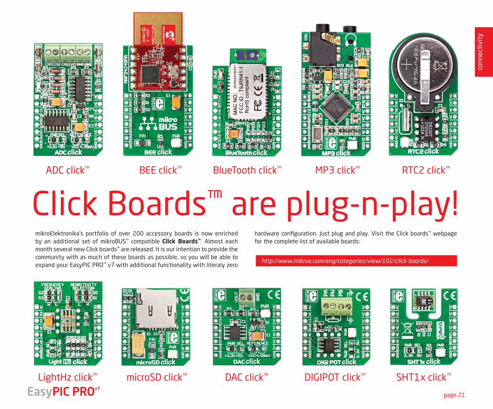
Click Boards™ are plug-n-play!ADC click™
LightHz click™ microSD click™ DAC click™ DIGIPOT click™ SHT1x click™
MP3 click™ RTC2 click™BEE click™ BlueTooth click™
mikroElektronika’s portfolio of over 200 accessory boards is now enriched by an additional set of mikroBUS™ compatible Click Boards™. Almost each month several new Click boards™ are released. It is our intention to provide the community with as much of these boards as possible, so you will be able to expand your EasyPIC PRO™ v7 with additional functionality with literaly zero
hardware configuration. Just plug and play. Visit the Click boards™ webpage for the complete list of available boards:
conn
ecti
vity
EasyPIC PROv7
http://www.mikroe.com/eng/categories/view/102/click-boards/
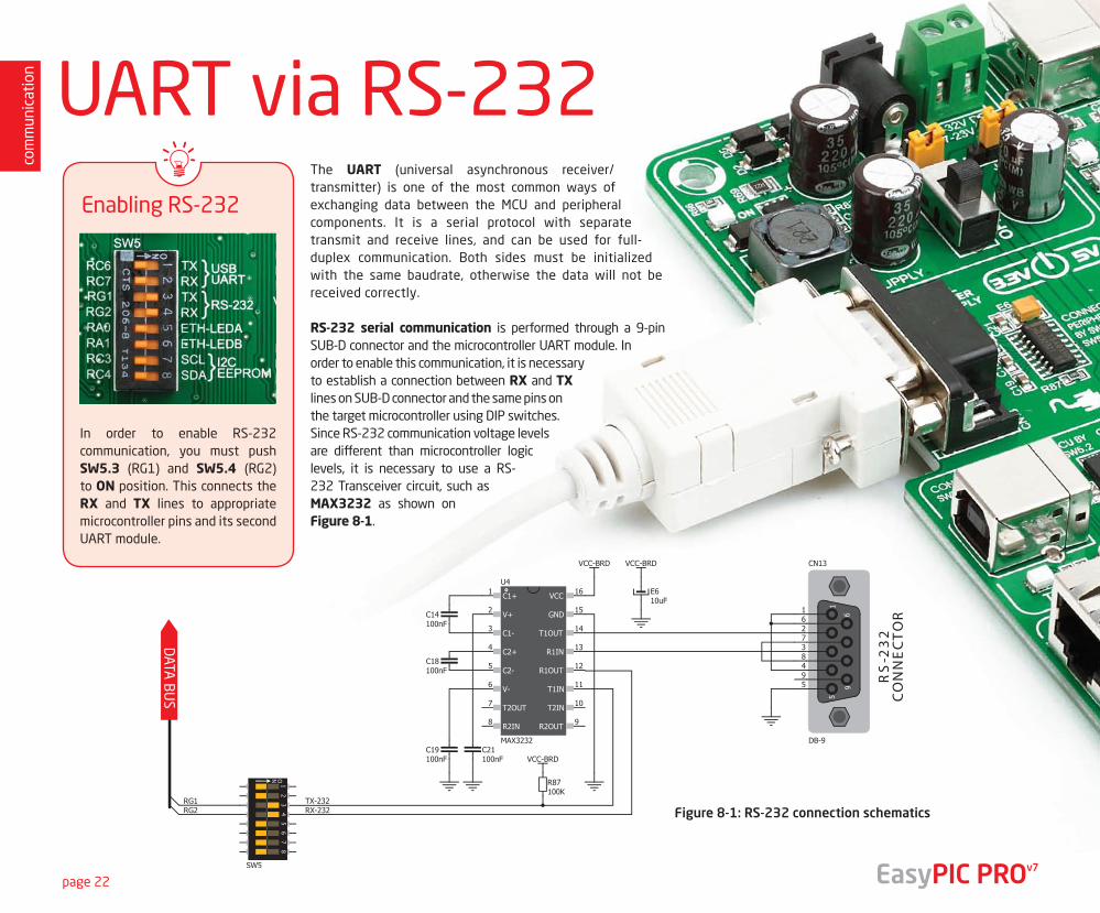
UART via RS-232The UART (universal asynchronous receiver/transmitter) is one of the most common ways of exchanging data between the MCU and peripheral components. It is a serial protocol with separate transmit and receive lines, and can be used for full-duplex communication. Both sides must be initialized with the same baudrate, otherwise the data will not be received correctly.
RS-232 serial communication is performed through a 9-pin SUB-D connector and the microcontroller UART module. In order to enable this communication, it is necessary to establish a connection between RX and TX lines on SUB-D connector and the same pins on the target microcontroller using DIP switches. Since RS-232 communication voltage levels are different than microcontroller logic levels, it is necessary to use a RS-232 Transceiver circuit, such as MAX3232 as shown on Figure 8-1.
DATA
BU
S
Figure 8-1: RS-232 connection schematics
Enabling RS-232
In order to enable RS-232 communication, you must push SW5.3 (RG1) and SW5.4 (RG2) to ON position. This connects the RX and TX lines to appropriate microcontroller pins and its second UART module.
com
mun
icat
ion
page 22 EasyPIC PROv7
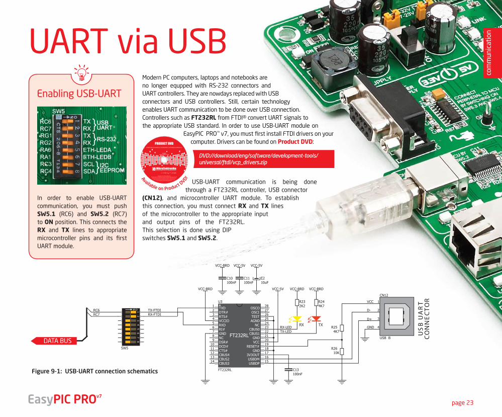
UART via USBModern PC computers, laptops and notebooks are no longer equpped with RS-232 connectors and UART controllers. They are nowdays replaced with USB connectors and USB controllers. Still, certain technology enables UART communication to be done over USB connection. Controllers such as FT232RL from FTDI® convert UART signals to the appropriate USB standard. In order to use USB-UART module on
EasyPIC PRO™ v7, you must first install FTDI drivers on your computer. Drivers can be found on Product DVD:
USB-UART communication is being done through a FT232RL controller, USB connector
(CN12), and microcontroller UART module. To establish this connection, you must connect RX and TX lines of the microcontroller to the appropriate input and output pins of the FT232RL. This selection is done using DIP switches SW5.1 and SW5.2.
DATA BUS
Figure 9-1: USB-UART connection schematics
Enabling USB-UART
DVD://download/eng/software/development-tools/universal/ftdi/vcp_drivers.zip
In order to enable USB-UART communication, you must push SW5.1 (RC6) and SW5.2 (RC7) to ON position. This connects the RX and TX lines to appropriate microcontroller pins and its first UART module.
com
mun
icat
ion
page 23EasyPIC PROv7
Available on Product DVD!
19122011 www.mikroe.com
Copyright ©2011 Mikroelektronika. All rights reserved. Mikroelektronika, Mikroelektronika logo and other
Mikroelektronika trademarks are the property of Mikroelektronika. All other tradmarks are the property of their respective owners.
Unauthorised copying, hiring, renting, public performance and broadcasting of this DVD prohibited.
page 24
USB devicecommunication
com
mun
icat
ion
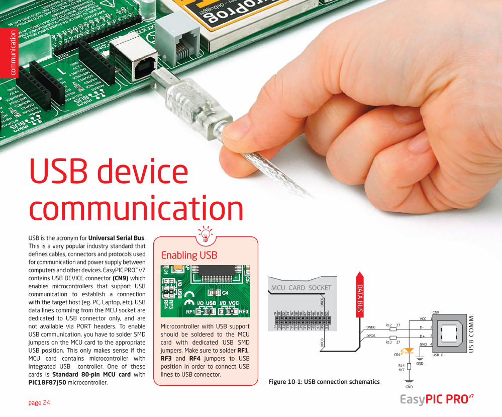
USB is the acronym for Universal Serial Bus. This is a very popular industry standard that defines cables, connectors and protocols used for communication and power supply between computers and other devices. EasyPIC PRO™ v7 contains USB DEVICE connector (CN9) which enables microcontrollers that support USB communication to establish a connection with the target host (eg. PC, Laptop, etc). USB data lines comming from the MCU socket are dedicated to USB connector only, and are not available via PORT headers. To enable USB communication, you have to solder SMD jumpers on the MCU card to the appropriate USB position. This only makes sense if the MCU card contains microcontroller with integrated USB controller. One of these cards is Standard 80-pin MCU card with PIC18F87J50 microcontroller.
DATA
BU
S
Enabling USB
Microcontroller with USB support should be soldered to the MCU card with dedicated USB SMD jumpers. Make sure to solder RF1, RF3 and RF4 jumpers to USB position in order to connect USB lines to USB connector.
Figure 10-1: USB connection schematics
EasyPIC PROv7
page 25
com
mun
icat
ion
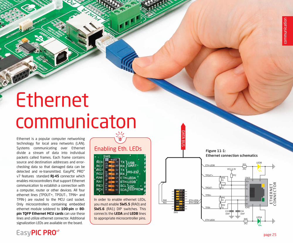
Ethernet is a popular computer networking technology for local area networks (LAN). Systems communicating over Ethernet divide a stream of data into individual packets called frames. Each frame contains source and destination addresses and error-checking data so that damaged data can be detected and re-transmitted. EasyPIC PRO™ v7 features standard RJ-45 connector which enables microcontrollers that support Ethernet communication to establish a connection with a computer, router or other devices. All four ethernet lines (TPOUT+, TPOUT-, TPIN+ and TPIN-) are routed to the MCU card socket. Only microcontrollers containing embedded ethernet module soldered to 100-pin or 80-pin TQFP Ethernet MCU cards can use these lines and utilize ethernet connector. Additional signalization LEDs are available on the board.
DATA
BU
S
Enabling Eth. LEDs
In order to enable ethernet LEDs, you must enable SW5.5 (RA0) and SW5.6 (RA1) DIP switches. This connects the LEDA and LEDB lines to appropriate microcontroller pins.
Figure 11-1: Ethernet connection schematics
Ethernetcommunicaton
EasyPIC PROv7
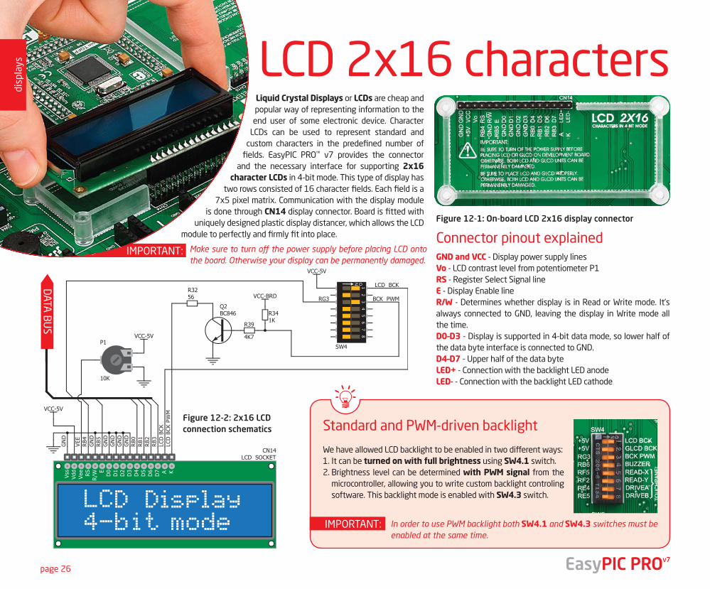
Liquid Crystal Displays or LCDs are cheap and popular way of representing information to the end user of some electronic device. Character
LCDs can be used to represent standard and custom characters in the predefined number of
fields. EasyPIC PRO™ v7 provides the connector and the necessary interface for supporting 2x16
character LCDs in 4-bit mode. This type of display has two rows consisted of 16 character fields. Each field is a
7x5 pixel matrix. Communication with the display module is done through CN14 display connector. Board is fitted with
uniquely designed plastic display distancer, which allows the LCD module to perfectly and firmly fit into place.
GND and VCC - Display power supply linesVo - LCD contrast level from potentiometer P1RS - Register Select Signal lineE - Display Enable lineR/W - Determines whether display is in Read or Write mode. It’s always connected to GND, leaving the display in Write mode all the time.D0–D3 - Display is supported in 4-bit data mode, so lower half of the data byte interface is connected to GND.D4–D7 - Upper half of the data byteLED+ - Connection with the backlight LED anodeLED- - Connection with the backlight LED cathode
We have allowed LCD backlight to be enabled in two different ways:1. It can be turned on with full brightness using SW4.1 switch.2. Brightness level can be determined with PWM signal from the
microcontroller, allowing you to write custom backlight controling software. This backlight mode is enabled with SW4.3 switch.
LCD 2x16 characters
DATA
BU
S
Figure 12-1: On-board LCD 2x16 display connector
Figure 12-2: 2x16 LCD connection schematics Standard and PWM-driven backlight
Connector pinout explainedMake sure to turn off the power supply before placing LCD onto the board. Otherwise your display can be permanently damaged.
In order to use PWM backlight both SW4.1 and SW4.3 switches must be enabled at the same time.
IMPORTANT:
IMPORTANT:
page 26
disp
lays
EasyPIC PROv7
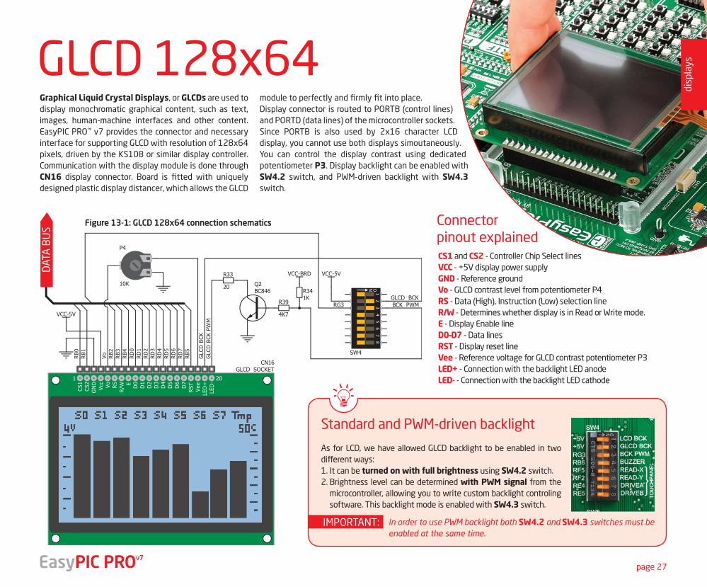
As for LCD, we have allowed GLCD backlight to be enabled in two different ways:1. It can be turned on with full brightness using SW4.2 switch.2. Brightness level can be determined with PWM signal from the
microcontroller, allowing you to write custom backlight controling software. This backlight mode is enabled with SW4.3 switch.
Graphical Liquid Crystal Displays, or GLCDs are used to display monochromatic graphical content, such as text, images, human-machine interfaces and other content. EasyPIC PRO™ v7 provides the connector and necessary interface for supporting GLCD with resolution of 128x64 pixels, driven by the KS108 or similar display controller. Communication with the display module is done through CN16 display connector. Board is fitted with uniquely designed plastic display distancer, which allows the GLCD
module to perfectly and firmly fit into place.Display connector is routed to PORTB (control lines) and PORTD (data lines) of the microcontroller sockets. Since PORTB is also used by 2x16 character LCD display, you cannot use both displays simoutaneously. You can control the display contrast using dedicated potentiometer P3. Display backlight can be enabled with SW4.2 switch, and PWM-driven backlight with SW4.3 switch.
GLCD 128x64D
ATA
BU
S
Standard and PWM-driven backlight
Connector pinout explained
In order to use PWM backlight both SW4.2 and SW4.3 switches must be enabled at the same time.
IMPORTANT:
CS1 and CS2 - Controller Chip Select linesVCC - +5V display power supplyGND - Reference groundVo - GLCD contrast level from potentiometer P4RS - Data (High), Instruction (Low) selection lineR/W - Determines whether display is in Read or Write mode.E - Display Enable lineD0–D7 - Data linesRST - Display reset lineVee - Reference voltage for GLCD contrast potentiometer P3LED+ - Connection with the backlight LED anodeLED- - Connection with the backlight LED cathode
page 27
disp
lays
EasyPIC PROv7
Figure 13-1: GLCD 128x64 connection schematics
page 28
disp
lays Touchpanel controller
Enabling Touch panel
Correctly placing the touchpanel cable into the connector
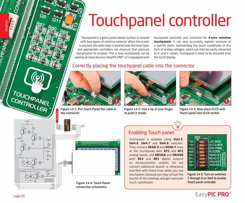
Touchpanel is a glass panel whose surface is covered with two layers of resistive material. When the screen
is pressed, the outer layer is pushed onto the inner layer and appropriate controllers can measure that pressure
and pinpoint its location. This is how touchpanels can be used as an input devices. EasyPIC PRO™ v7 is equipped with
touchpanel controller and connector for 4-wire resistive touchpanels. It can very accurately register pressure at a specific point, representing the touch coordinates in the form of analog voltages, which can then be easily converted to X- and Y- values. Touchpanel is ment to be mounted onto the GLCD display.
Figure 14-1: Put Touch Panel flat cable in the connector
Figure 14-2: Use a tip of your finger to push it inside
Figure 14-3: Now place GLCD with Touch panel into GLCD socket
1 2 3
Figure 14-5: Turn on switches 5 through 8 on SW4 to enable Touch panel controller
Touchpanel is enabled using SW4.5, SW4.6, SW4.7 and SW4.8 switches. They connect READ-X and READ-Y lines of the touchpanel with RF5 and RF2 analog inputs, and DRIVEA and DRIVEB with RE4 and RE5 digital outputs on microcontroller sockets. Do not connect additional boards or otherwise interfere with these lines while you use touchpanel, because you may corrupt the results of the readings and get inacurate touch coordinates.
DAT
A B
US
READ-XREAD-Y
EasyPIC PROv7
Figure 14-4: Touch Panel connection schematics
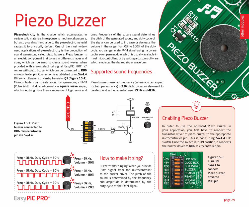
Piezoelectricity is the charge which accumulates in certain solid materials in response to mechanical pressure, but also providing the charge to the piezoelectric material causes it to physically deform. One of the most widely used applications of piezoelectricity is the production of sound generators, called piezo buzzers. Piezo buzzer is an electric component that comes in different shapes and sizes, which can be used to create sound waves when provided with analog electrical signal. EasyPIC PRO™ v7 comes with piezo buzzer which can be connected to RB6 microcontroller pin. Connection is established using SW4.4 DIP switch. Buzzer is driven by transistor Q1 (Figure 15-1). Microcontrollers can create sound by generating a PWM (Pulse Width Modulated) signal – a square wave signal, which is nothing more than a sequence of logic zeros and
ones. Frequency of the square signal determines the pitch of the generated sound, and duty cycle of the signal can be used to increase or decrease the volume in the range from 0% to 100% of the duty cycle. You can generate PWM signal using hardware capture-compare module, which is usually available in most microcontrollers, or by writing a custom software which emulates the desired signal waveform.
Supported sound frequencies
Piezo buzzer’s resonant frequency (where you can expect it's best performance) is 3.8kHz, but you can also use it to create sound in the range between 2kHz and 4kHz.
Figure 15-2:Turn ON SW4.4 to connectPiezo buzzer driver to RB6 pin
PERSPECTIVEVIEW
TOPVIEW
DATA
BU
S
In order to use the on-board Piezo Buzzer in your application, you first have to connect the transistor driver of piezo buzzer to the appropriate microcontroller pin. This is done using SW4.4 DIP switch. Once the switch is in ON position, it connects the buzzer driver to RB6 microcontroller pin.
Buzzer starts "singing" when you provide PWM signal from the microcontroller to the buzzer driver. The pitch of the sound is determined by the frequency, and amplitude is determined by the duty cycle of the PWM signal.
Enabling Piezo Buzzer
How to make it sing?
Figure 15-1: Piezo buzzer connected to RB6 microcontroller pin via SW4.4
Freq = 3kHz, Duty Cycle = 50% Freq = 3kHz, Volume = 50%
Freq = 3kHz, Volume = 80%
Freq = 3kHz, Volume = 20%
Freq = 3kHz, Duty Cycle = 80%
Freq = 3kHz, Duty Cycle = 20%
TO S
OCK
ETS
VCC-5V
R31KPZ1
Q8BC846
10K
R27
PERSPECTIVEVIEW
TOPVIEW
RE1
RC2J21
BUZZER
TO S
OCK
ETS
VCC-5V
R31KPZ1
Q8BC846
10K
R27
PERSPECTIVEVIEW
TOPVIEW
RE1
RC2J21
BUZZER
TO S
OCK
ETS
VCC-5V
R31KPZ1
Q8BC846
10K
R27
PERSPECTIVEVIEW
TOPVIEW
RE1
RC2J21
BUZZER
Piezo Buzzer
page 29
othe
r mod
ules
EasyPIC PROv7
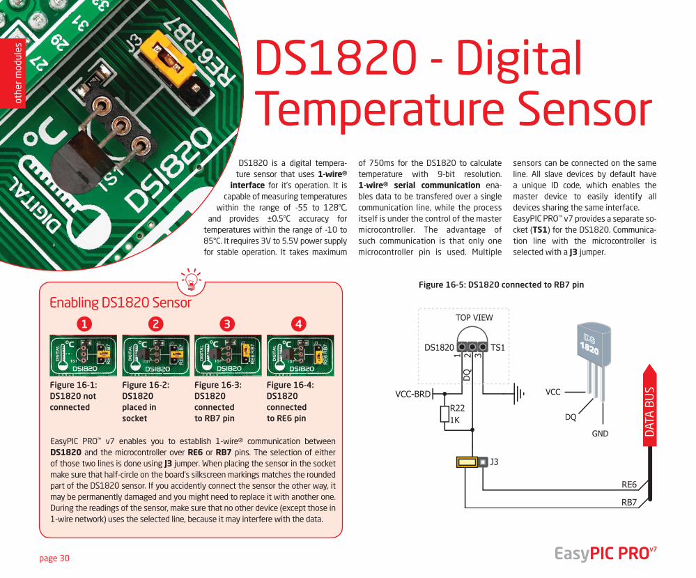
DS1820 is a digital tempera-ture sensor that uses 1-wire®
interface for it’s operation. It is capable of measuring temperatures
within the range of -55 to 128°C, and provides ±0.5°C accuracy for
temperatures within the range of -10 to 85°C. It requires 3V to 5.5V power supply for stable operation. It takes maximum
of 750ms for the DS1820 to calculate temperature with 9-bit resolution. 1-wire® serial communication ena-bles data to be transfered over a single communication line, while the process itself is under the control of the master microcontroller. The advantage of such communication is that only one microcontroller pin is used. Multiple
sensors can be connected on the same line. All slave devices by default have a unique ID code, which enables the master device to easily identify all devices sharing the same interface.EasyPIC PRO™ v7 provides a separate so-cket (TS1) for the DS1820. Communica-tion line with the microcontroller is selected with a J3 jumper.
DS1820 - Digital Temperature Sensor
page 30
DAT
A B
US
EasyPIC PRO™ v7 enables you to establish 1-wire® communication between DS1820 and the microcontroller over RE6 or RB7 pins. The selecti on of either of those two lines is done using J3 jumper. When placing the sensor in the socket make sure that half-circle on the board’s silkscreen markings matches the rounded part of the DS1820 sensor. If you accidently connect the sensor the other way, it may be permanently damaged and you might need to replace it with another one. During the readings of the sensor, make sure that no other device (except those in 1-wire network) uses the selected line, because it may interfere with the data.
Figure 16-1:DS1820 not connected
Figure 16-2:DS1820 placed in socket
Figure 16-3:DS1820 connected to RB7 pin
Figure 16-4:DS1820 connected to RE6 pin
Figure 16-5: DS1820 connected to RB7 pin
Enabling DS1820 Sensor1 2 3 4
othe
r mod
ules
EasyPIC PROv7
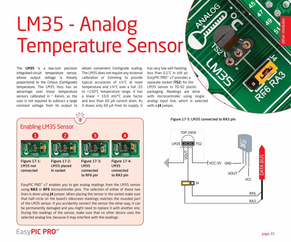
The LM35 is a low-cost precision integrated-circuit temperature sensor, whose output voltage is linearly proportional to the Celsius (Centigrade) temperature. The LM35 thus has an advantage over linear temperature sensors calibrated in ° Kelvin, as the user is not required to subtract a large constant voltage from its output to
obtain convenient Centigrade scaling. The LM35 does not require any external calibration or trimming to provide typical accuracies of ±¼°C at room temperature and ±¾°C over a full -55 to +150°C temperature range. It has a linear + 10.0 mV/°C scale factor and less than 60 μA current drain. As it draws only 60 μA from its supply, it
has very low self-heating, less than 0.1°C in still air. EasyPIC PRO™ v7 provides a separate socket (TS2) for the LM35 sensor in TO-92 plastic packaging. Readings are done with microcontroller using single analog input line, which is selected with a J4 jumper.
page 31
DAT
A B
US
Figure 17-5: LM35 connected to RA3 pin
EasyPIC PRO™ v7 enables you to get analog readings from the LM35 sensor using RA3 or RF6 microcontroller pins. The selection of either of those two lines is done using J4 jumper. When placing the sensor in the socket make sure that half-circle on the board’s silkscreen markings matches the rounded part of the LM35 sensor. If you accidently connect the sensor the other way, it can be permanently damaged and you might need to replace it with another one. During the readings of the sensor, make sure that no other device uses the selected analog line, because it may interfere with the readings.
Figure 17-1:LM35 not connected
Figure 17-2:LM35 placed in socket
Figure 17-3:LM35 connected to RF6 pin
Figure 17-4:LM35 connected to RA3 pin
Enabling LM35 Sensor1 2 3 4
LM35 - AnalogTemperature Sensor ot
her m
odul
es
EasyPIC PROv7
page 32
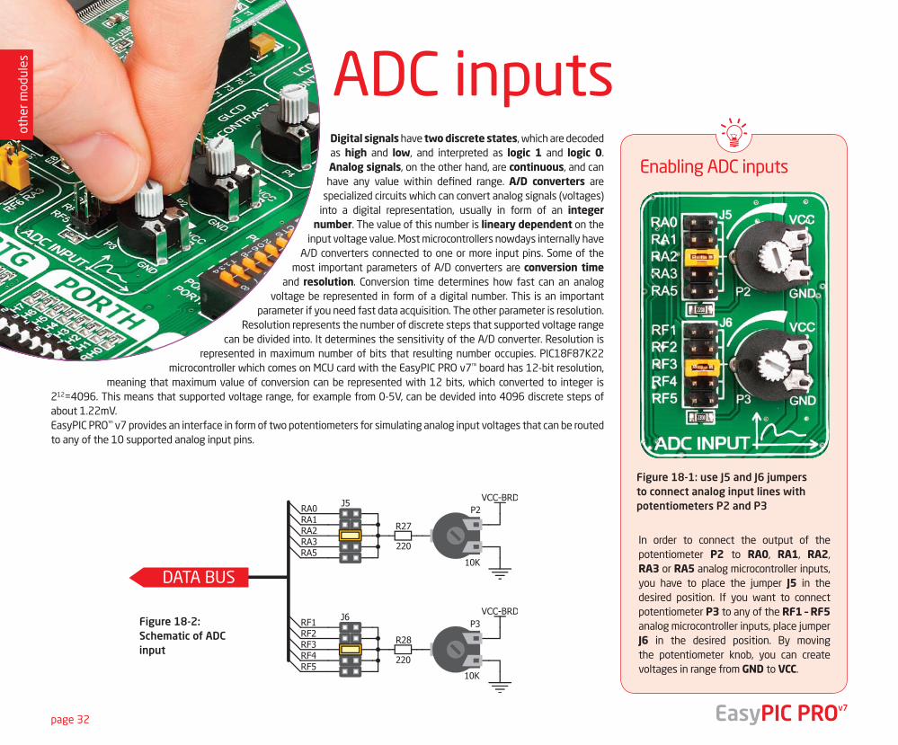
Digital signals have two discrete states, which are decoded as high and low, and interpreted as logic 1 and logic 0. Analog signals, on the other hand, are continuous, and can have any value within defined range. A/D converters are
specialized circuits which can convert analog signals (voltages) into a digital representation, usually in form of an integer
number. The value of this number is lineary dependent on the input voltage value. Most microcontrollers nowdays internally have
A/D converters connected to one or more input pins. Some of the most important parameters of A/D converters are conversion time
and resolution. Conversion time determines how fast can an analog voltage be represented in form of a digital number. This is an important
parameter if you need fast data acquisition. The other parameter is resolution. Resolution represents the number of discrete steps that supported voltage range
can be divided into. It determines the sensitivity of the A/D converter. Resolution is represented in maximum number of bits that resulting number occupies. PIC18F87K22
microcontroller which comes on MCU card with the EasyPIC PRO v7™ board has 12-bit resolution, meaning that maximum value of conversion can be represented with 12 bits, which converted to integer is
212=4096. This means that supported voltage range, for example from 0-5V, can be devided into 4096 discrete steps of about 1.22mV. EasyPIC PRO™ v7 provides an interface in form of two potentiometers for simulating analog input voltages that can be routed to any of the 10 supported analog input pins.
ADC inputs
DATA BUS
Enabling ADC inputs
In order to connect the output of the potentiometer P2 to RA0, RA1, RA2, RA3 or RA5 analog microcontroller inputs, you have to place the jumper J5 in the desired position. If you want to connect potentiometer P3 to any of the RF1 – RF5 analog microcontroller inputs, place jumper J6 in the desired position. By moving the potentiometer knob, you can create voltages in range from GND to VCC.
Figure 18-1: use J5 and J6 jumpers to connect analog input lines with potentiometers P2 and P3
Figure 18-2:Schematic of ADC input
EasyPIC PROv7
othe
r mod
ules
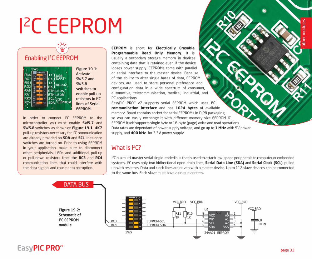
EEPROM is short for Electrically Erasable Programmable Read Only Memory. It is usually a secondary storage memory in devices containing data that is retained even if the device looses power supply. EEPROMs come with parallel or serial interface to the master device. Because of the ability to alter single bytes of data, EEPROM devices are used to store personal preference and configuration data in a wide spectrum of consumer, automotive, telecommunication, medical, industrial, and PC applications. EasyPIC PRO™ v7 supports serial EEPROM which uses I2C communication interface and has 1024 bytes of available memory. Board contains socket for serial EEPROMs in DIP8 packaging, so you can easily exchange it with different memory size EEPROM IC. EEPROM itself supports single byte or 16-byte (page) write and read operations. Data rates are dependant of power supply voltage, and go up to 1 MHz with 5V power supply, and 400 kHz for 3.3V power supply.
othe
r mod
ules
page 33
I2C EEPROM
In order to connect I2C EEPROM to the microcontroller you must enable SW5.7 and SW5.8 switches, as shown on Figure 19-1. 4K7 pull-up resistors necessary for I2C communication are already provided on SDA and SCL lines once switches are turned on. Prior to using EEPROM in your application, make sure to disconnect other peripherials, LEDs and additional pull-up or pull-down resistors from the RC3 and RC4 communication lines that could interfere with the data signals and cause data corruption.
I2C is a multi-master serial single-ended bus that is used to attach low-speed peripherals to computer or embedded systems. I²C uses only two bidirectional open-drain lines, Serial Data Line (SDA) and Serial Clock (SCL), pulled up with resistors. Data and clock lines are driven with a master device. Up to 112 slave devices can be connected to the same bus. Each slave must have a unique address.
DATA BUS
Enabling I2C EEPROM
What is I2C?
Figure 19-1: Activate SW5.7 and SW5.8 switches to enable pull-up resistors in I2C lines of Serial EEPROM.
Figure 19-2:Schematic ofI2C EEPROM module
EasyPIC PROv7
othe
r mod
ules
page 34 EasyPIC PROv7
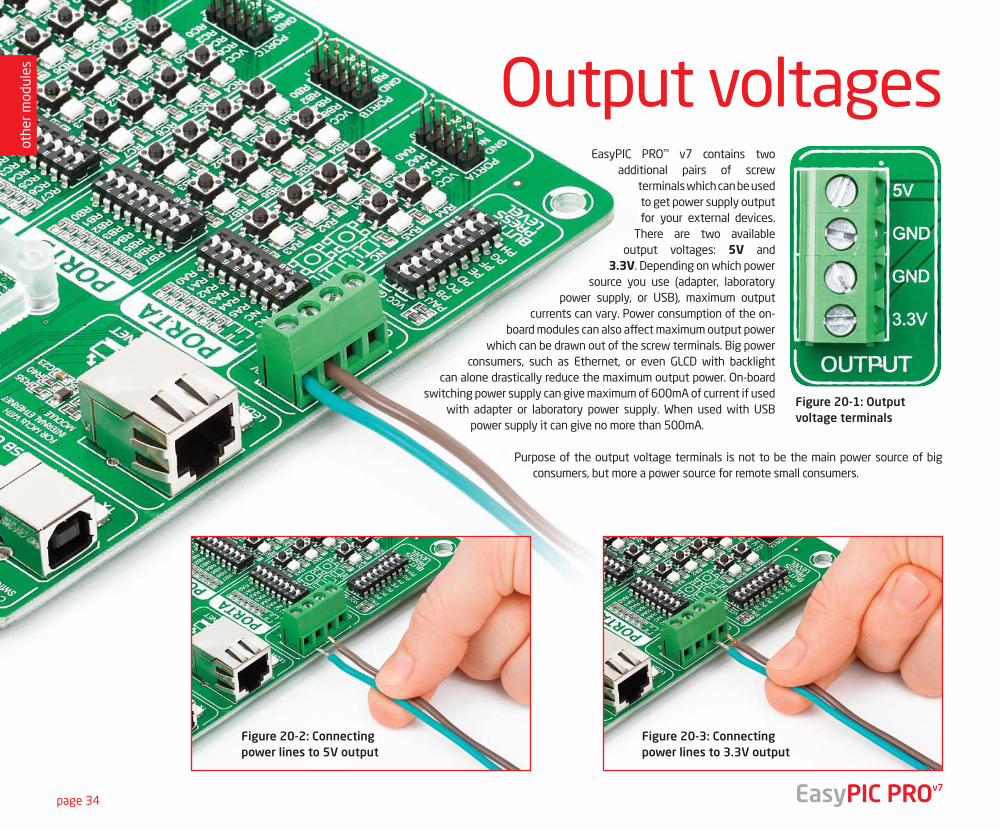
EasyPIC PRO™ v7 contains two additional pairs of screw
terminals which can be used to get power supply output for your external devices.
There are two available output voltages: 5V and
3.3V. Depending on which power source you use (adapter, laboratory
power supply, or USB), maximum output currents can vary. Power consumption of the on-
board modules can also affect maximum output power which can be drawn out of the screw terminals. Big power
consumers, such as Ethernet, or even GLCD with backlight can alone drastically reduce the maximum output power. On-board
switching power supply can give maximum of 600mA of current if used with adapter or laboratory power supply. When used with USB
power supply it can give no more than 500mA.
Purpose of the output voltage terminals is not to be the main power source of big consumers, but more a power source for remote small consumers.
Output voltages
Figure 20-1: Output voltage terminals
Figure 20-2: Connecting power lines to 5V output
Figure 20-3: Connecting power lines to 3.3V output
othe
r mod
ules
page 35
2
1
3
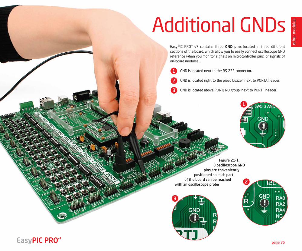
Figure 21-1:3 oscilloscope GND
pins are conveniently positioned so each part
of the board can be reached with an oscilloscope probe
EasyPIC PRO™ v7 contains three GND pins located in three different sections of the board, which allow you to easily connect oscilloscope GND reference when you monitor signals on microcontroller pins, or signals of on-board modules.
GND is located next to the RS-232 connector.
GND is located right to the piezo buzzer, next to PORTA header.
GND is located above PORTJ I/O group, next to PORTF header.
Additional GNDs
1
2
3
EasyPIC PROv7

page 36
What’s Next?
You still don’t have an appropriate compiler? Locate PIC® compiler that suits you best on the Product DVD provided with the package:
Choose between mikroC, mikroBasic and mikroPascal and download fully functional demo version, so you can begin building your PIC® applications.
Once you have chosen your compiler, and since you already got the board, you are ready to start writing your first projects. We have equipped our compilers with dozens of examples that demonstrate the use of each and every feature of the EasyPIC PRO™ v7 board, and all of our accessory boards as well. This makes an excellent starting point for your future projects. Just load the example, read well commented code, and see how it works on hardware. Browse through the compiler Examples path to find the following folder:
You have now completed the journey through each and every feature of EasyPIC PRO™ v7 board. You got to know it’s modules, organization, supported microcontrollers, programmer and debugger. Now you are ready to start using your new board. We are suggesting several steps which are probably the best way to begin. We invite you to join thousands of users of EasyPIC™ brand. You will find very useful projects and tutorials and can get help from a large ecosystem of users. Welcome!
Compiler
Projects
DVD://download/eng/software/compilers/
\Development Systems\EASYPIC_PROv7
If you want to find answers to your questions on many interesting topics we invite you to visit our forum at http://www.mikroe.com/forum and browse through more than 150 thousand posts. You are likely to find just the right information for you. On the other hand, if you want to download free projects and libraries, or share your own code, please visit the Libstock website. With user profiles, you can get to know other programmers, and subscribe to receive notifications on their code.
http://www.libstock.com/
CommunityWe all know how important it is that we can rely on someone in moments when we are stuck with our projects, facing a deadline, or when we just want to ask a simple, basic question, that’s pulling us back for a while. We do understand how important this is to people and therefore our Support Department is one of the pillars upon which our company is based. MikroElektronika offers Free Tech Support to the end of product lifetime, so if something goes wrong, we are ready and willing to help!
http://www.mikroe.com/esupport/
Support
EasyPIC PROv7
Available on Product DVD!
19122011 www.mikroe.com
Copyright ©2011 Mikroelektronika. All rights reserved. Mikroelektronika, Mikroelektronika logo and other
Mikroelektronika trademarks are the property of Mikroelektronika. All other tradmarks are the property of their respective owners.
Unauthorised copying, hiring, renting, public performance and broadcasting of this DVD prohibited.
page 37EasyPIC PROv7
note
s
page 38 EasyPIC PROv7
note
s

DISCLAIMERAll the products owned by MikroElektronika are protected by copyright law and international copyright treaty. Therefore, this manual is to be treated as any other copyright material. No part of this manual, including product and software described herein, must not be reproduced, stored in a retrieval system, translated or transmitted in any form or by any means, without the prior written permission of MikroElektronika. The manual PDF edition can be printed for private or local use, but not for distribution. Any modification of this manual is prohibited.
MikroElektronika provides this manual ‘as is’ without warranty of any kind, either expressed or implied, including, but not limited to, the implied warranties or conditions of merchantability or fitness for a particular purpose.
MikroElektronika shall assume no responsibility or liability for any errors, omissions and inaccuracies that may appear in this manual. In no event shall MikroElektronika, its directors, officers, employees or distributors be liable for any indirect, specific, incidental or consequential damages (including damages for loss of business profits and business information, business interruption or any other pecuniary loss) arising out of the use of this manual or product, even if MikroElektronika has been advised of the possibility of such damages. MikroElektronika reserves the right to change information contained in this manual at any time without prior notice, if necessary.
TRADEMARKS
The MikroElektronika name and logo, the MikroElektronika logo, mikroC™, mikroBasic™, mikroPascal™, mikroProg™, EasyPIC™, EasyPIC PRO™, mikroBus™ and Click boards™ are trademarks of MikroElektronika. All other trademarks mentioned herein are property of their respective companies.
All other product and corporate names appearing in this manual may or may not be registered trademarks or copyrights of their respective companies, and are only used for identification or explanation and to the owners’ benefit, with no intent to infringe.
Copyright © MikroElektronika™, 2012, All Rights Reserved.
HIGH RISK ACTIVITIES
The products of MikroElektronika are not fault – tolerant nor designed, manufactured or intended for use or resale as on – line control equipment in hazardous environments requiring fail – safe performance, such as in the operation of nuclear facilities, aircraft navigation or communication systems, air traffic control, direct life support machines or weapons systems in which the failure of Software could lead directly to death, personal injury or severe physical or environmental damage (‘High Risk Activities’). MikroElektronika and its suppliers specifically disclaim any expressed or implied warranty of fitness for High Risk Activities.

If you want to learn more about our products, please visit our website at www.mikroe.comIf you are experiencing some problems with any of our products or just need additional
information, please place your ticket at www.mikroe.com/esupportIf you have any questions, comments or business proposals,
do not hesitate to contact us at [email protected]
EasyPIC PRO v7 User Manualver 1.00
Related Documents