Mercury Baseboard Reference Manual www.micro-nova.com © 2015 MicroNova LLC www.micro-nova.com OVERVIEW The Baseboard is a great addition to the Mercury Module, providing a host of on-board components that can be used to design and test a wide variety of digital and analog circuits. The 4 seven-segment displays are great for debugging designs. The switches, buttons, and keyboard/mouse inputs come in handy for receiving user input. A Digilent® Pmod™ compatible port is also included for adding on a wide variety of peripheral modules. An assortment of analog sensors are available on the Baseboard for use with Mercury’s on-board ADC. For more advanced projects, circuitry is included for audio input and output, as well as VGA output for interfacing with an LCD or CRT monitor. Use the Baseboard for quick design and testing of your projects, then pop the Mercury module out and insert into your own custom design! FEATURES 4-digit seven-segment display 4 pushbuttons and 8 slide switches PS/2 port for keyboard and/or mouse input VGA port supporting 8-bit color 1 Double Pmod™ compatible connector Socket for external oscillator Audio out port and support circuitry for 1-bit oversampling DAC audio Audio input port and support circuitry for use with Mercury’s ADC Analog temperature sensor, light sensor, and potentiometer for use with Mercury’s ADC JTAG pin header

Welcome message from author
This document is posted to help you gain knowledge. Please leave a comment to let me know what you think about it! Share it to your friends and learn new things together.
Transcript
Mercury Baseboard Reference Manual
www.micro-nova.com
© 2015 MicroNova LLC
www.micro-nova.com
OVERVIEW
The Baseboard is a great addition to the Mercury Module, providing a host of on-board components
that can be used to design and test a wide variety of digital and analog circuits. The 4 seven-segment
displays are great for debugging designs. The switches, buttons, and keyboard/mouse inputs come in
handy for receiving user input. A Digilent® Pmod™ compatible port is also included for adding on a wide
variety of peripheral modules. An assortment of analog sensors are available on the Baseboard for use
with Mercury’s on-board ADC. For more advanced projects, circuitry is included for audio input and
output, as well as VGA output for interfacing with an LCD or CRT monitor.
Use the Baseboard for quick design and testing of your projects, then pop the Mercury module out and
insert into your own custom design!
FEATURES
4-digit seven-segment display
4 pushbuttons and 8 slide switches
PS/2 port for keyboard and/or mouse input
VGA port supporting 8-bit color
1 Double Pmod™ compatible connector
Socket for external oscillator
Audio out port and support circuitry for 1-bit oversampling DAC audio
Audio input port and support circuitry for use with Mercury’s ADC
Analog temperature sensor, light sensor, and potentiometer for use with Mercury’s ADC
JTAG pin header
MERCURY REFERENCE MANUAL 2 of 8
© 2015 MicroNova LLC
www.micro-nova.com Page 2 of 8
GETTING STARTED
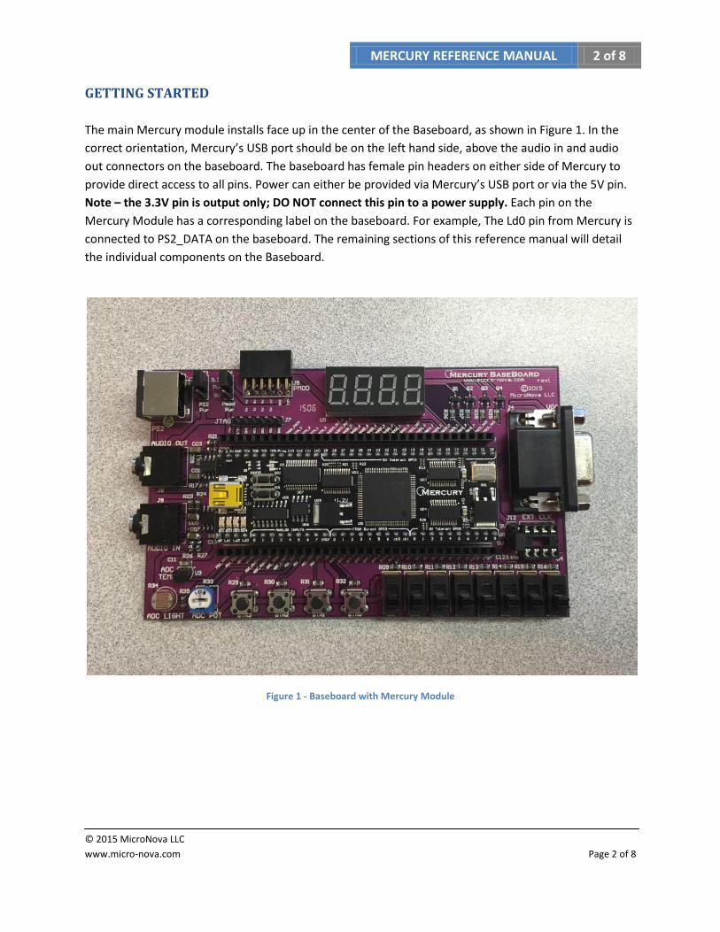
The main Mercury module installs face up in the center of the Baseboard, as shown in Figure 1. In the
correct orientation, Mercury’s USB port should be on the left hand side, above the audio in and audio
out connectors on the baseboard. The baseboard has female pin headers on either side of Mercury to
provide direct access to all pins. Power can either be provided via Mercury’s USB port or via the 5V pin.
Note – the 3.3V pin is output only; DO NOT connect this pin to a power supply. Each pin on the
Mercury Module has a corresponding label on the baseboard. For example, The Ld0 pin from Mercury is
connected to PS2_DATA on the baseboard. The remaining sections of this reference manual will detail
the individual components on the Baseboard.
Figure 1 - Baseboard with Mercury Module
MERCURY REFERENCE MANUAL 3 of 8
© 2015 MicroNova LLC
www.micro-nova.com Page 3 of 8
PUSHBUTTONS
The Baseboard has 4 pushbutton switches, BTN3 – BTN0, which are wired to Mercury’s input only pins.
Each pushbutton is connected to 3.3V and also has a 4.7K pull-down resistor. This provides the FPGA
with a logic low input when not pressed and logic high when pressed. Table 1 provides the pin mappings
for the pushbuttons: Table 1 - Pushbutton pin mappings
Baseboard Pin Mercury Pin FPGA pin
BTN_0 FPGA_IN_0 P68 BTN_1 FPGA_IN_1 P97 BTN_2 FPGA_IN_2 P7 BTN_3 FPGA_IN_3 P82
SLIDE SWITCHES
The eight slide switches available on the Baseboard are wired to the GPIO pins on Mercury. Each
double-throw switch is wired to 3.3V on one side and GND on the other side, providing a logic low input
when in the down position and logic high in the up position. Table 2 provides the pin mappings for the
pushbuttons: Table 2 - Slide switch pin mappings
Baseboard Pin Mercury Pin FPGA pin
SW_0 IO_0 P59 SW_1 IO_1 P60 SW_2 IO_2 P61 SW_3 IO_3 P62 SW_4 IO_4 P64 SW_5 IO_5 P57 SW_6 IO_6 P56 SW_7 IO_7 P52
SEVEN SEGMENT DISPLAYS
The baseboard has a 4-digit seven-segment display array. Each seven-segment display consists of
individual segments that can be lit up in various combinations to display alpha-numeric digits. For more
information about seven-segment displays, have a look at this great Wikipedia article:
http://en.wikipedia.org/wiki/Seven-segment_display
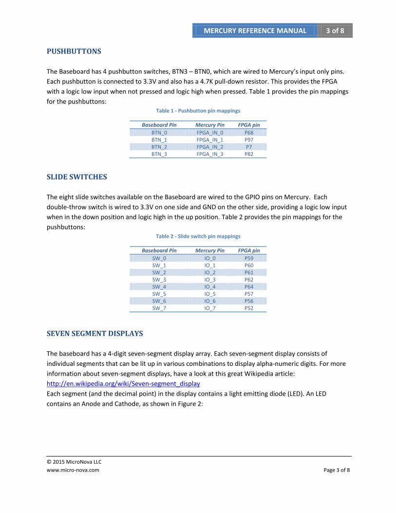
Each segment (and the decimal point) in the display contains a light emitting diode (LED). An LED
contains an Anode and Cathode, as shown in Figure 2:
MERCURY REFERENCE MANUAL 4 of 8
© 2015 MicroNova LLC
www.micro-nova.com Page 4 of 8
Figure 2 - LED symbol
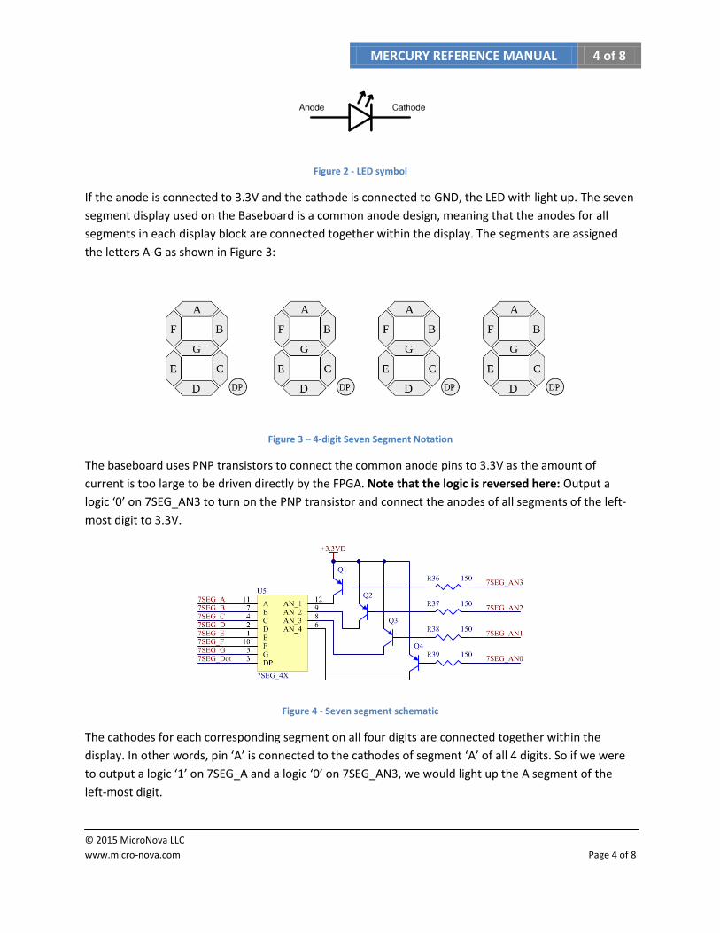
If the anode is connected to 3.3V and the cathode is connected to GND, the LED with light up. The seven
segment display used on the Baseboard is a common anode design, meaning that the anodes for all
segments in each display block are connected together within the display. The segments are assigned
the letters A-G as shown in Figure 3:
Figure 3 – 4-digit Seven Segment Notation
The baseboard uses PNP transistors to connect the common anode pins to 3.3V as the amount of
current is too large to be driven directly by the FPGA. Note that the logic is reversed here: Output a
logic ‘0’ on 7SEG_AN3 to turn on the PNP transistor and connect the anodes of all segments of the left-
most digit to 3.3V.
Figure 4 - Seven segment schematic
The cathodes for each corresponding segment on all four digits are connected together within the
display. In other words, pin ‘A’ is connected to the cathodes of segment ‘A’ of all 4 digits. So if we were
to output a logic ‘1’ on 7SEG_A and a logic ‘0’ on 7SEG_AN3, we would light up the A segment of the
left-most digit.
MERCURY REFERENCE MANUAL 5 of 8
© 2015 MicroNova LLC
www.micro-nova.com Page 5 of 8
In order to display different values on each segment, we need to implement some type of multiplexing
logic on the FPGA. The idea here is that we can scan through each segment and momentarily display the
correct character. If we scan through each of the 4 digits quick enough, it will appear as if we are
updating all four digits simultaneously. Table 3 provides the pin mappings for the seven segment
displays:
Table 3 – Seven segment display pin mappings
Baseboard Pin Mercury Pin FPGA pin
AN_0 IO8 P50 AN_1 IO9 P49 AN_2 IO10 P85 AN_3 IO11 P84
A IO12 P72 B IO13 P71 C IO14 P70 D IO15 P65 E IO16 P77 F IO17 P78 G IO18 P83
DOT IO19 P73
PMOD™ COMPATIBLE CONNECTOR
On the top left side of the Baseboard is a dual row Pmod™ compatible connector. This can be used to
connect to a wide variety of low frequency, low I/O pin count peripheral modules –DAC/ADC boards,
wireless modules, motor/servo controllers, accelerometers, etc.
The dual row connector contains two 6-pin compatible Pmod™ interfaces stacked. Two 6-pin modules
can be connected to the port using a splitter cable available from most sources that sell Pmod™
modules. When looking at the connector from the side, the pin-out is as follows:
VCC GND P3 P2 P1 P0
VCC GND P7 P6 P5 P4
VCC can be either 5V or 3.3V depending on the position of J6. Table 4 provides the pin mappings for the
Pmod™ connector:
MERCURY REFERENCE MANUAL 6 of 8
© 2015 MicroNova LLC
www.micro-nova.com Page 6 of 8
Table 4 - PMOD pin mappings
Baseboard Pin Mercury Pin FPGA pin
PMOD0 IO20 P5 PMOD1 IO21 P4 PMOD2 IO22 P6 PMOD3 IO23 P98 PMOD4 IO24 P94 PMOD5 IO25 P93 PMOD6 IO26 P90 PMOD7 IO27 P89
PS/2 PORT
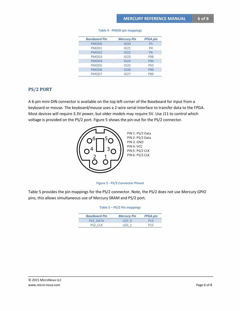
A 6-pin mini-DIN connector is available on the top left corner of the Baseboard for input from a
keyboard or mouse. The keyboard/mouse uses a 2-wire serial interface to transfer data to the FPGA.
Most devices will require 3.3V power, but older models may require 5V. Use J11 to control which
voltage is provided on the PS/2 port. Figure 5 shows the pin-out for the PS/2 connector.
Figure 5 - PS/2 Connector Pinout
Table 5 provides the pin mappings for the PS/2 connector. Note, the PS/2 does not use Mercury GPIO
pins, this allows simultaneous use of Mercury SRAM and PS/2 port.
Table 5 – PS/2 Pin mappings
Baseboard Pin Mercury Pin FPGA pin
PS2_DATA LED_0 P13 PS2_CLK LED_1 P15
MERCURY REFERENCE MANUAL 7 of 8
© 2015 MicroNova LLC
www.micro-nova.com Page 7 of 8
VGA PORT
On the right side of the Baseboard you will find a standard VGA port that can be connected to any
CRT/LCD computer display with a VGA interface. The VGA port contains an HSYNC and VSYNC pin for
control, as well as 3 pins for setting the pixel color – red, green, and blue. The analog voltage of each of
these 3 pins controls the color of the pixel. The Baseboard uses 8 of Mercury’s FPGA direct I/O pins to
set the color of each pixel. 3 pins control the red color, 3 pins control the green color, and 2 pins control
the blue. The eye is less sensitive to blue; therefore we can get away with having fewer color choices. A series of voltage dividers is used to control the analog voltage on each color pin. Setting the 3 red color pins to logic ‘0’ creates a voltage of 0V, setting all 3 red pins to logic ‘1’ creates a voltage of 0.7V. Any value in between 000 and 111 will create a voltage between these two extremes. With these 8 color control pins, we can display 256 unique colors on the
monitor. Note that the VGA port does not use Mercury GPIO pins, therefore the SRAM onboard Mercury can be used as a frame buffer if necessary.
Table 6 provides the pin mappings for the PS/2 connector.
Table 6 - VGA pin mappings
Baseboard Pin Mercury Pin FPGA pin
RED0 DIRECT_IO_0 P20 RED1 DIRECT_IO_1 P32 RED2 DIRECT_IO_2 P33 GRN0 DIRECT_IO_3 P34 GRN1 DIRECT_IO_4 P35 GRN2 DIRECT_IO_5 P36 BLU0 DIRECT_IO_6 P37 BLU1 CLK_IO_0 P40
HSYNC LED_2 P16 VSYNC LED_3 P19
ADC INPUT DEVICES
Potentiometer
On the lower left corner of the Baseboard is a 10K potentiometer. The top leg is connected to 5V and
the bottom leg is connected to ground. The wiper is connected to the ADC channel 4. The potentiometer
can be adjusted to output a voltage between 0V and 5V to the ADC.

MERCURY REFERENCE MANUAL 8 of 8
© 2015 MicroNova LLC
www.micro-nova.com Page 8 of 8
Temp Sensor
The lower left corner of the Baseboard also contains a Microchip MCP9701 Active Thermistor. The
datasheet is available at http://ww1.microchip.com/downloads/en/DeviceDoc/20001942F.pdf. The
Thermistor can measure temperatures from -40°C to +125°C with ±4°C accuracy. The device outputs a
voltage of 400mV at 0°C. For each 1°C rise in temperature, the output voltage increases by 19.5mV. The
output of the temp sensor is connected to ADC channel 2.
Light Sensor
Also in the lower left corner of the Baseboard is a photocell. This sensor can be used to detect light. This
photocell will change resistance based on the amount of light it receives. The photocell is connected in
series with a 4.7K resistor to form a divider. The resistance of the photocell will range between 5 KΩ in
full light to approx 3 MΩ in darkness. The divider voltage is connected to ADC channel 3. A great tutorial
on photocells is available at https://learn.adafruit.com/photocells/
Audio Input
On the left side of the Baseboard above the temp sensor is a 3.5mm stereo audio input jack. After
entering the baseboard, each channel (Left and Right) of the audio signal is first AC coupled, and then DC
biased to 2.5V. This centers the audio signals within the range of the ADC. The channels are then
buffered and ran through low pass filters. The final signals are then connected to channels 0 and 1 of
Mercury’s ADC.
AUDIO OUTPUT
Above the audio input jack is a 3.5mm stereo audio output jack. Through a technique known as 1-bit
DAC audio, we can output stereo audio using only 2 GPIO pins on Mercury. A great tutorial on this
technique can be found at http://www.fpga4fun.com/PWM_DAC.html
1 bit audio works much like PWM, in that our single digital pin is switched on and off very quickly to
create an average value that approximates the audio signal level at any given time. This output signal is
then fed through a low-pass filter on the baseboard, which will smooth out the PWM signal. The signal is
then buffered and AC coupled for output to a pair of headphones or computer speakers.
Related Documents