1 2. The STM32F4-Discovery BaseBoard The description of the extension board based on the STM32F Discovery is given in this chapter. Full schematic diagrams and PCB layouts are presented, including figures on signal connections. 2.1. The processor board There are many different kinds of microcontrollers available, and all are optimal from a certain point of view. The experiments that are to be performed in this course require a microcontroller that is capable of typical data processing tasks in real time; the processor must be fast, preferably 32 bit type. Analog signals will be used as a source of information, therefore the microcontroller must be capable of converting analog signals to digital values and back. Additionally, the microcontroller should have provisions for typical buses as used in contemporary interfacing, like I2C, SPI, and RS232. An exchange of data between the microcontroller and a personal computer must be feasible. The microcontroller is to be programmed using a “free” version of compiler, the preferred programming language is “C”. No operating system will be used. The hardware needed for programming of the microcontroller should be freely available. Due to its convenient properties and low price the STM32F4-Discovery demo board is selected for this course. The demo board can be obtained for as low as 15€, and includes the microcontroller STM32F407VGT (32bit, ARM Cortex-M4F core, 1MB Flash memory, 192kB RAM), some interfacing hardware, and the programmer. The board is powered through an USB connector from a host personal computer. Most of the microcontroller pins are available at two header connectors on the board. The board can be used without any additional hardware, and the detailed description is given at: http://www.st.com/web/catalog/tools/FM116/SC959/SS1532/PF252419 (as of Nov. 2013) 2.2. The extension - BaseBoard The STM32F4-Discovery board hosts a microcontroller with most of its pins exposed at the header connectors, Fig. 2.2. In order to prevent damage caused by either static electricity or experimenting faults a BaseBoard has been prepared. This board is a EURO size printed circuit board with header sockets that accept headers of the STM32F4-Discovery board, and includes protection circuits and additional hardware to improve the interfacing experience, see Fig. 2.2.13 for signal names at header pins. 2.2.1. The BaseBoard power supply, Fig. 2.2.1 The power to run STM32F4-Discovery board is normally supplied from a USB cable connected to a personal computer (PC). However, there are times when the board is to be used without the connection to the PC, and in such cases the board needs an alternative power supply. This can be any source capable of providing a voltage between 8V and 25V, 0.25A min. This source can be connected to the BaseBoard using pads B200 and B201; there is a protective diode D270 to prevent damage due

Welcome message from author
This document is posted to help you gain knowledge. Please leave a comment to let me know what you think about it! Share it to your friends and learn new things together.
Transcript
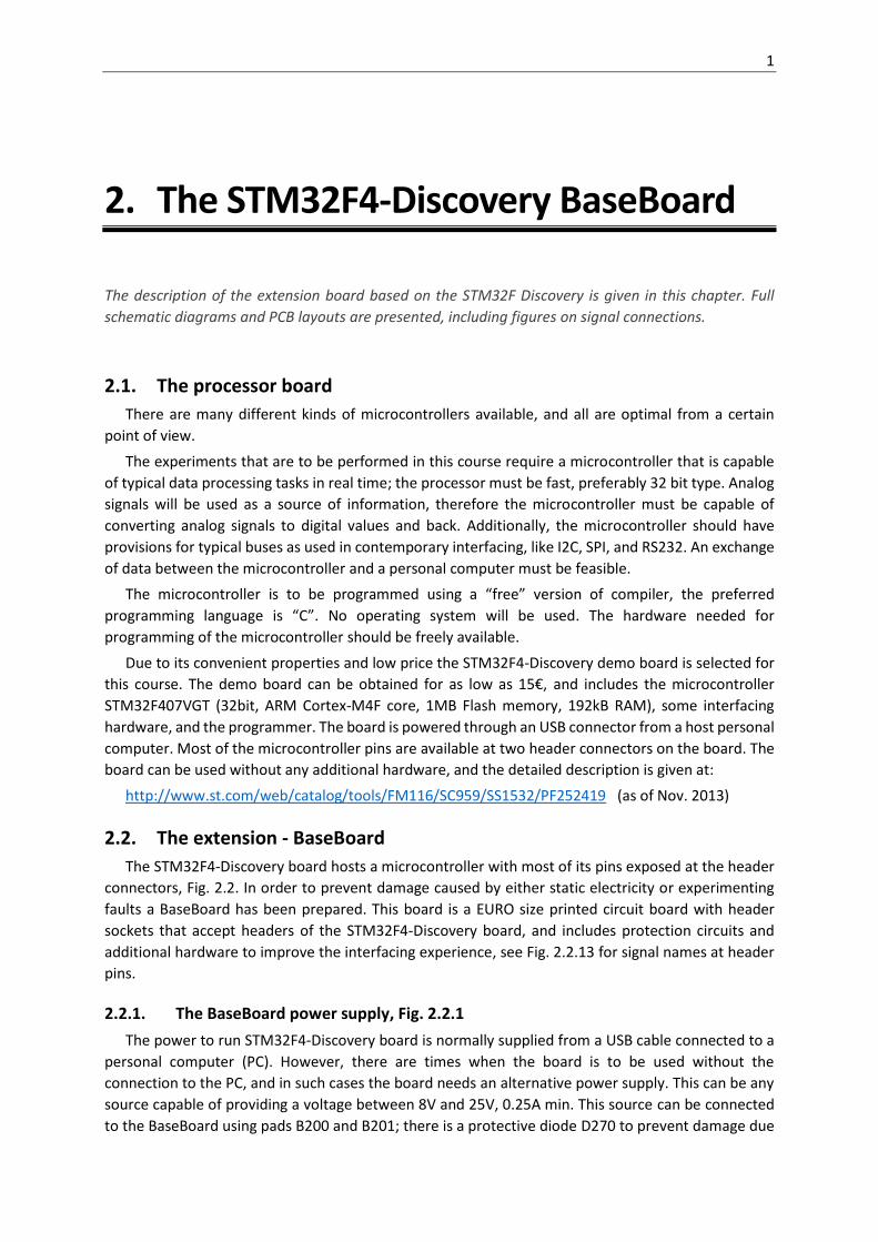
1
2. The STM32F4-Discovery BaseBoard
The description of the extension board based on the STM32F Discovery is given in this chapter. Full
schematic diagrams and PCB layouts are presented, including figures on signal connections.
2.1. The processor board
There are many different kinds of microcontrollers available, and all are optimal from a certain
point of view.
The experiments that are to be performed in this course require a microcontroller that is capable
of typical data processing tasks in real time; the processor must be fast, preferably 32 bit type. Analog
signals will be used as a source of information, therefore the microcontroller must be capable of
converting analog signals to digital values and back. Additionally, the microcontroller should have
provisions for typical buses as used in contemporary interfacing, like I2C, SPI, and RS232. An exchange
of data between the microcontroller and a personal computer must be feasible.
The microcontroller is to be programmed using a “free” version of compiler, the preferred
programming language is “C”. No operating system will be used. The hardware needed for
programming of the microcontroller should be freely available.
Due to its convenient properties and low price the STM32F4-Discovery demo board is selected for
this course. The demo board can be obtained for as low as 15€, and includes the microcontroller
STM32F407VGT (32bit, ARM Cortex-M4F core, 1MB Flash memory, 192kB RAM), some interfacing
hardware, and the programmer. The board is powered through an USB connector from a host personal
computer. Most of the microcontroller pins are available at two header connectors on the board. The
board can be used without any additional hardware, and the detailed description is given at:
http://www.st.com/web/catalog/tools/FM116/SC959/SS1532/PF252419 (as of Nov. 2013)
2.2. The extension - BaseBoard
The STM32F4-Discovery board hosts a microcontroller with most of its pins exposed at the header
connectors, Fig. 2.2. In order to prevent damage caused by either static electricity or experimenting
faults a BaseBoard has been prepared. This board is a EURO size printed circuit board with header
sockets that accept headers of the STM32F4-Discovery board, and includes protection circuits and
additional hardware to improve the interfacing experience, see Fig. 2.2.13 for signal names at header
pins.
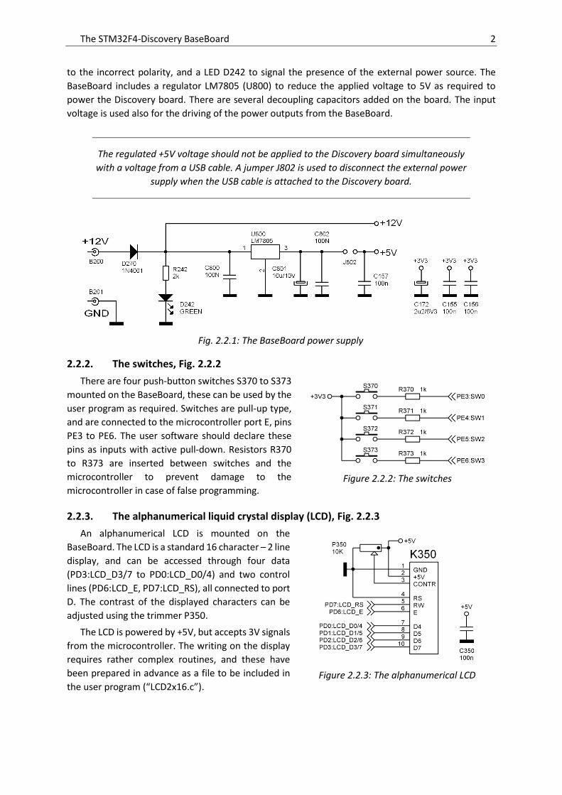
2.2.1. The BaseBoard power supply, Fig. 2.2.1
The power to run STM32F4-Discovery board is normally supplied from a USB cable connected to a
personal computer (PC). However, there are times when the board is to be used without the
connection to the PC, and in such cases the board needs an alternative power supply. This can be any
source capable of providing a voltage between 8V and 25V, 0.25A min. This source can be connected
to the BaseBoard using pads B200 and B201; there is a protective diode D270 to prevent damage due
The STM32F4-Discovery BaseBoard 2
to the incorrect polarity, and a LED D242 to signal the presence of the external power source. The
BaseBoard includes a regulator LM7805 (U800) to reduce the applied voltage to 5V as required to
power the Discovery board. There are several decoupling capacitors added on the board. The input
voltage is used also for the driving of the power outputs from the BaseBoard.
The regulated +5V voltage should not be applied to the Discovery board simultaneously
with a voltage from a USB cable. A jumper J802 is used to disconnect the external power
supply when the USB cable is attached to the Discovery board.
2.2.2. The switches, Fig. 2.2.2
There are four push-button switches S370 to S373
mounted on the BaseBoard, these can be used by the
user program as required. Switches are pull-up type,
and are connected to the microcontroller port E, pins
PE3 to PE6. The user software should declare these
pins as inputs with active pull-down. Resistors R370
to R373 are inserted between switches and the
microcontroller to prevent damage to the
microcontroller in case of false programming.
2.2.3. The alphanumerical liquid crystal display (LCD), Fig. 2.2.3
An alphanumerical LCD is mounted on the
BaseBoard. The LCD is a standard 16 character – 2 line
display, and can be accessed through four data
(PD3:LCD_D3/7 to PD0:LCD_D0/4) and two control
lines (PD6:LCD_E, PD7:LCD_RS), all connected to port
D. The contrast of the displayed characters can be
adjusted using the trimmer P350.
The LCD is powered by +5V, but accepts 3V signals
from the microcontroller. The writing on the display
requires rather complex routines, and these have
been prepared in advance as a file to be included in
the user program (“LCD2x16.c”).
Fig. 2.2.1: The BaseBoard power supply
Figure 2.2.2: The switches
Figure 2.2.3: The alphanumerical LCD
The STM32F4-Discovery BaseBoard 3
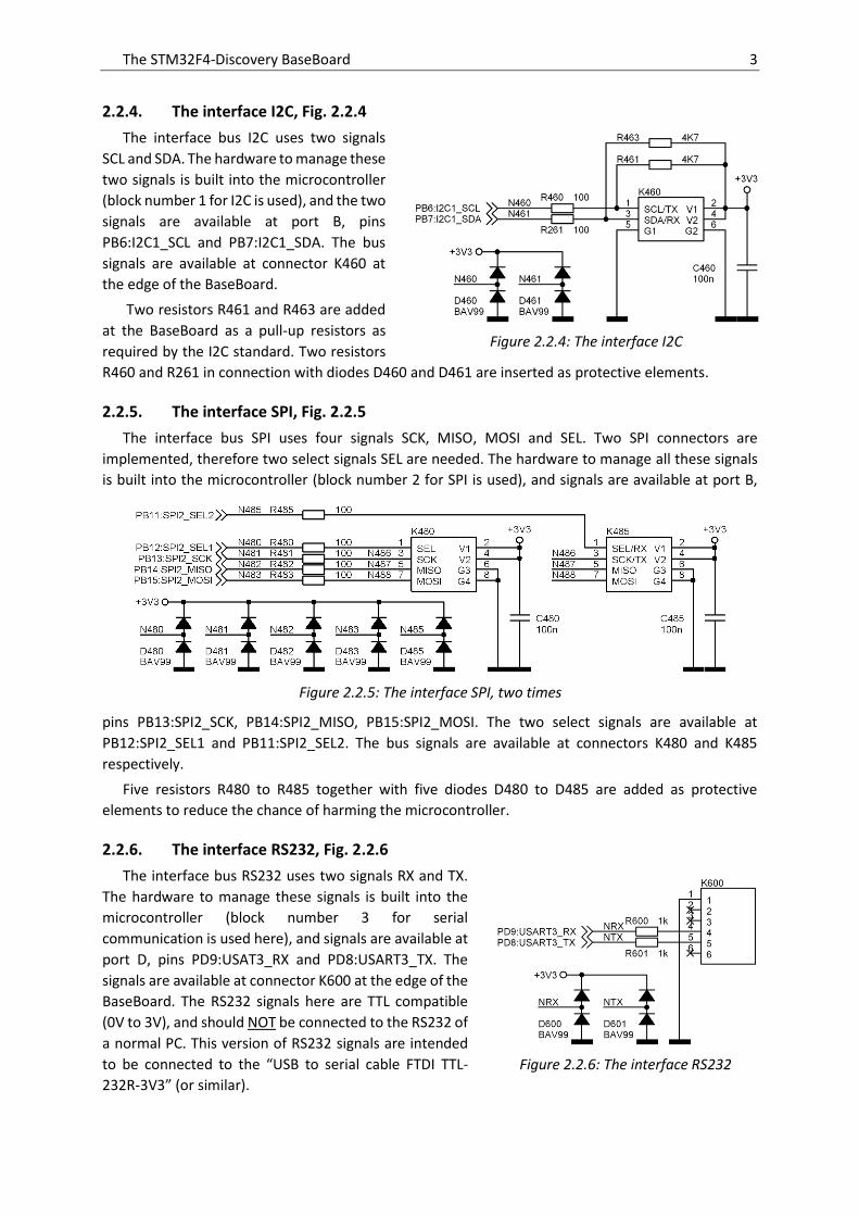
2.2.4. The interface I2C, Fig. 2.2.4
The interface bus I2C uses two signals
SCL and SDA. The hardware to manage these
two signals is built into the microcontroller
(block number 1 for I2C is used), and the two
signals are available at port B, pins
PB6:I2C1_SCL and PB7:I2C1_SDA. The bus
signals are available at connector K460 at
the edge of the BaseBoard.
Two resistors R461 and R463 are added
at the BaseBoard as a pull-up resistors as
required by the I2C standard. Two resistors
R460 and R261 in connection with diodes D460 and D461 are inserted as protective elements.
2.2.5. The interface SPI, Fig. 2.2.5
The interface bus SPI uses four signals SCK, MISO, MOSI and SEL. Two SPI connectors are
implemented, therefore two select signals SEL are needed. The hardware to manage all these signals
is built into the microcontroller (block number 2 for SPI is used), and signals are available at port B,
pins PB13:SPI2_SCK, PB14:SPI2_MISO, PB15:SPI2_MOSI. The two select signals are available at
PB12:SPI2_SEL1 and PB11:SPI2_SEL2. The bus signals are available at connectors K480 and K485
respectively.
Five resistors R480 to R485 together with five diodes D480 to D485 are added as protective
elements to reduce the chance of harming the microcontroller.
2.2.6. The interface RS232, Fig. 2.2.6
The interface bus RS232 uses two signals RX and TX.
The hardware to manage these signals is built into the
microcontroller (block number 3 for serial
communication is used here), and signals are available at
port D, pins PD9:USAT3_RX and PD8:USART3_TX. The
signals are available at connector K600 at the edge of the
BaseBoard. The RS232 signals here are TTL compatible
(0V to 3V), and should NOT be connected to the RS232 of
a normal PC. This version of RS232 signals are intended
to be connected to the “USB to serial cable FTDI TTL-
232R-3V3” (or similar).
Figure 2.2.4: The interface I2C
Figure 2.2.5: The interface SPI, two times
Figure 2.2.6: The interface RS232
The STM32F4-Discovery BaseBoard 4
Two resistors R600 and R601 in combination with two diodes D600 and D601 are used as protective
elements.
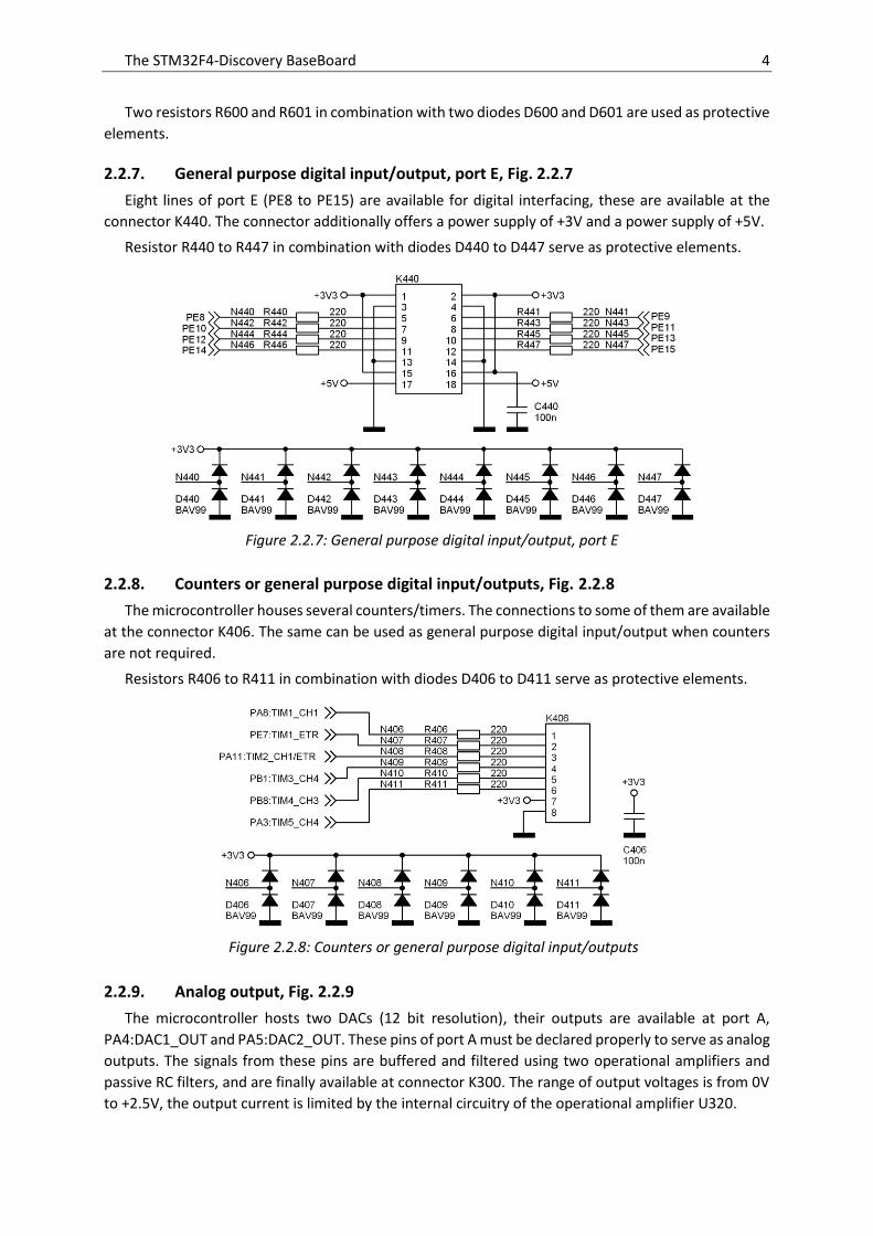
2.2.7. General purpose digital input/output, port E, Fig. 2.2.7
Eight lines of port E (PE8 to PE15) are available for digital interfacing, these are available at the
connector K440. The connector additionally offers a power supply of +3V and a power supply of +5V.
Resistor R440 to R447 in combination with diodes D440 to D447 serve as protective elements.
2.2.8. Counters or general purpose digital input/outputs, Fig. 2.2.8
The microcontroller houses several counters/timers. The connections to some of them are available
at the connector K406. The same can be used as general purpose digital input/output when counters
are not required.
Resistors R406 to R411 in combination with diodes D406 to D411 serve as protective elements.
2.2.9. Analog output, Fig. 2.2.9
The microcontroller hosts two DACs (12 bit resolution), their outputs are available at port A,
PA4:DAC1_OUT and PA5:DAC2_OUT. These pins of port A must be declared properly to serve as analog
outputs. The signals from these pins are buffered and filtered using two operational amplifiers and
passive RC filters, and are finally available at connector K300. The range of output voltages is from 0V
to +2.5V, the output current is limited by the internal circuitry of the operational amplifier U320.
Figure 2.2.7: General purpose digital input/output, port E
Figure 2.2.8: Counters or general purpose digital input/outputs

The STM32F4-Discovery BaseBoard 5
The pins PA4 and PA5 are used on the STM23F4-Discovery board to drive
digital inputs of peripheral chips. In order to fully utilize the properties of DAC, the
PCB traces to these peripheral chips should be cut.
2.2.10. Analog input, Fig. 2.2.10
The microcontroller hosts three ADCs (12 bit resolution each), and three multiplexers to connect
signals from several pins of the microcontroller to each of them. The BaseBoard utilizes four pins to
measure external analog signals, these are PA1:ADC123_IN1, PA2:ADC123_IN2, PC1:ADC123_IN11,
and PC2:ADC123_IN12. These pins must be initialized to analog mode prior to the use of the ADC
function, and external analog signals can be connected to connector K300.
Figure 2.2.9: Analog output
Figure 2.2.10: Analog input, the connector is given in Fig. 2.2.9
The STM32F4-Discovery BaseBoard 6
Input signals are fed to four identical stages before being passed to the microcontroller. Each stage
consists of a voltage divider (resistors R300, R301, capacitor C301 and jumper J301 for the first stage).
The divider is followed by a unity gain connected operational amplifier U300A and an RC low-pass filter
(R302 and C302). A double diode D301 is connected to the non-inverting input of the operational
amplifier, and serves as a protective element.
The input range depends on the position of the jumper (J301 for the first stage):
- Jumper not inserted: range is 0V to +3V3 (Vref of the microcontroller)
- Jumper shorts R301 to ground: range is 0V to two times +3V3 (2 x Vref of the microcontroller)
- Jumper shorts R301 and +3V3: range is -3V3 to +3V3.
Both RC time constants limit the input frequency range to 1MHz.
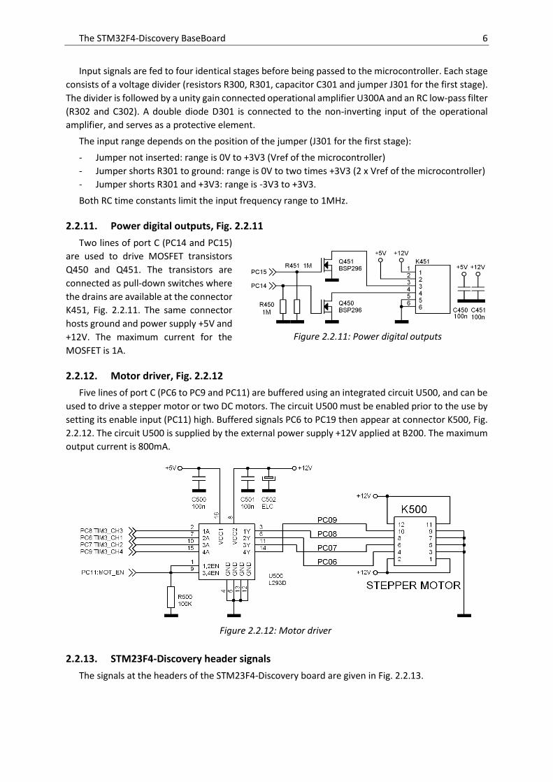
2.2.11. Power digital outputs, Fig. 2.2.11
Two lines of port C (PC14 and PC15)
are used to drive MOSFET transistors
Q450 and Q451. The transistors are
connected as pull-down switches where
the drains are available at the connector
K451, Fig. 2.2.11. The same connector
hosts ground and power supply +5V and
+12V. The maximum current for the
MOSFET is 1A.
2.2.12. Motor driver, Fig. 2.2.12
Five lines of port C (PC6 to PC9 and PC11) are buffered using an integrated circuit U500, and can be
used to drive a stepper motor or two DC motors. The circuit U500 must be enabled prior to the use by
setting its enable input (PC11) high. Buffered signals PC6 to PC19 then appear at connector K500, Fig.
2.2.12. The circuit U500 is supplied by the external power supply +12V applied at B200. The maximum
output current is 800mA.
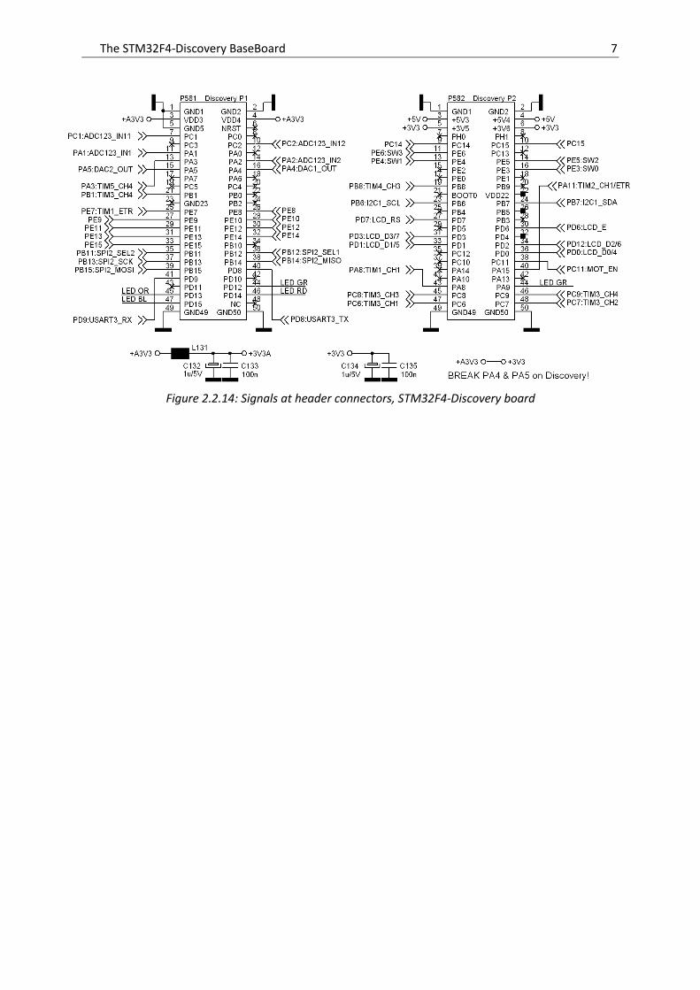
2.2.13. STM23F4-Discovery header signals
The signals at the headers of the STM23F4-Discovery board are given in Fig. 2.2.13.
Figure 2.2.11: Power digital outputs
Figure 2.2.12: Motor driver
The STM32F4-Discovery BaseBoard 7
Figure 2.2.14: Signals at header connectors, STM32F4-Discovery board

The STM32F4-Discovery BaseBoard 8
Figure 2.2.15: BaseBoard, component layout
The STM32F4-Discovery BaseBoard 9
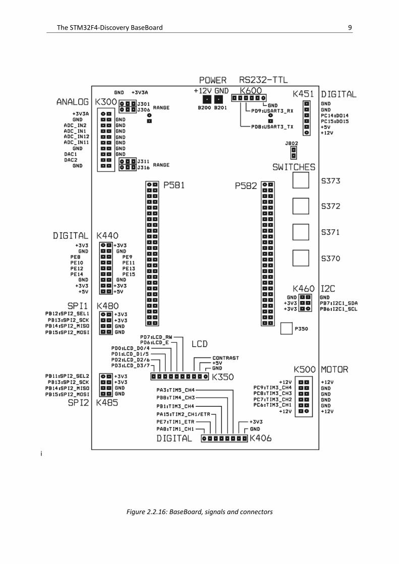
Figure 2.2.16: BaseBoard, signals and connectors
i
The STM32F4-Discovery BaseBoard 10
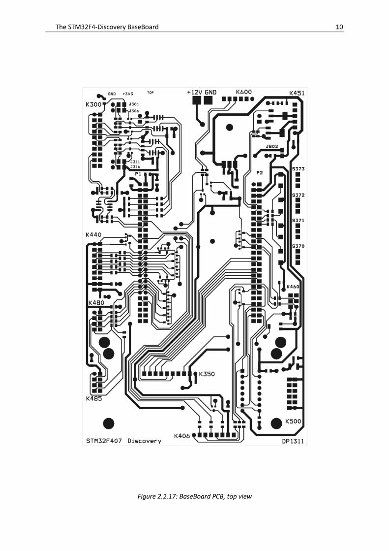
Figure 2.2.17: BaseBoard PCB, top view
The STM32F4-Discovery BaseBoard 11
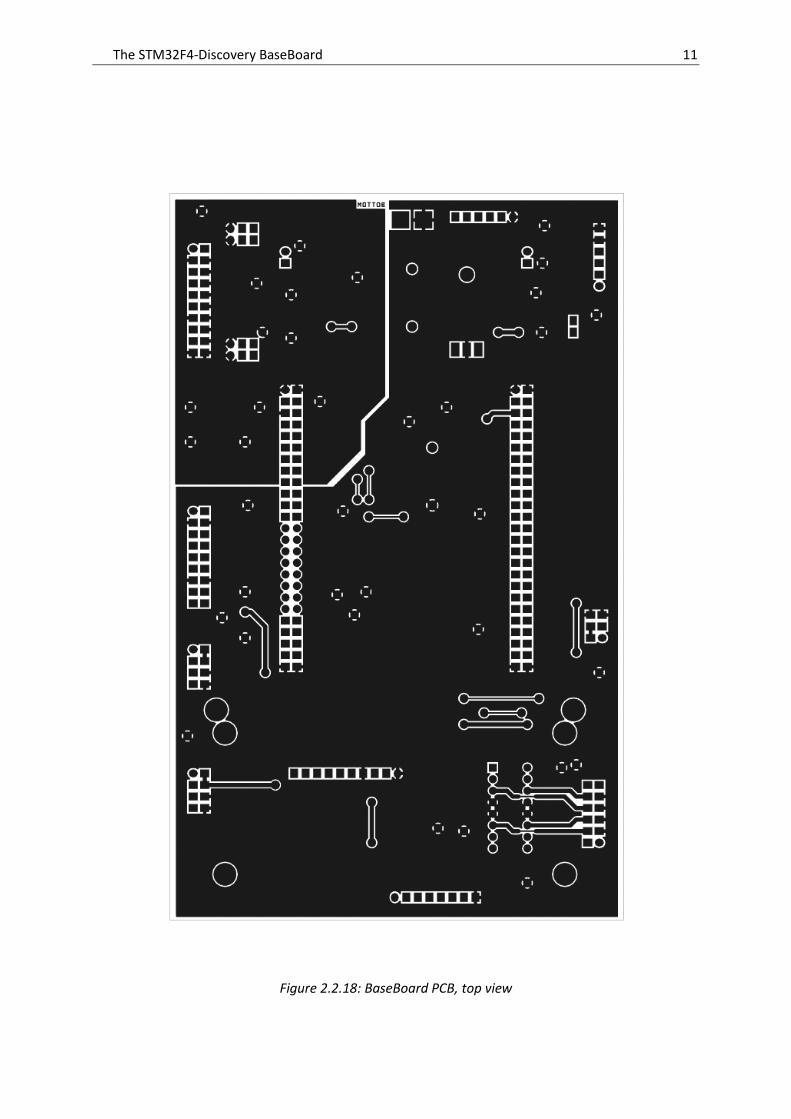
Figure 2.2.18: BaseBoard PCB, top view
The STM32F4-Discovery BaseBoard 12
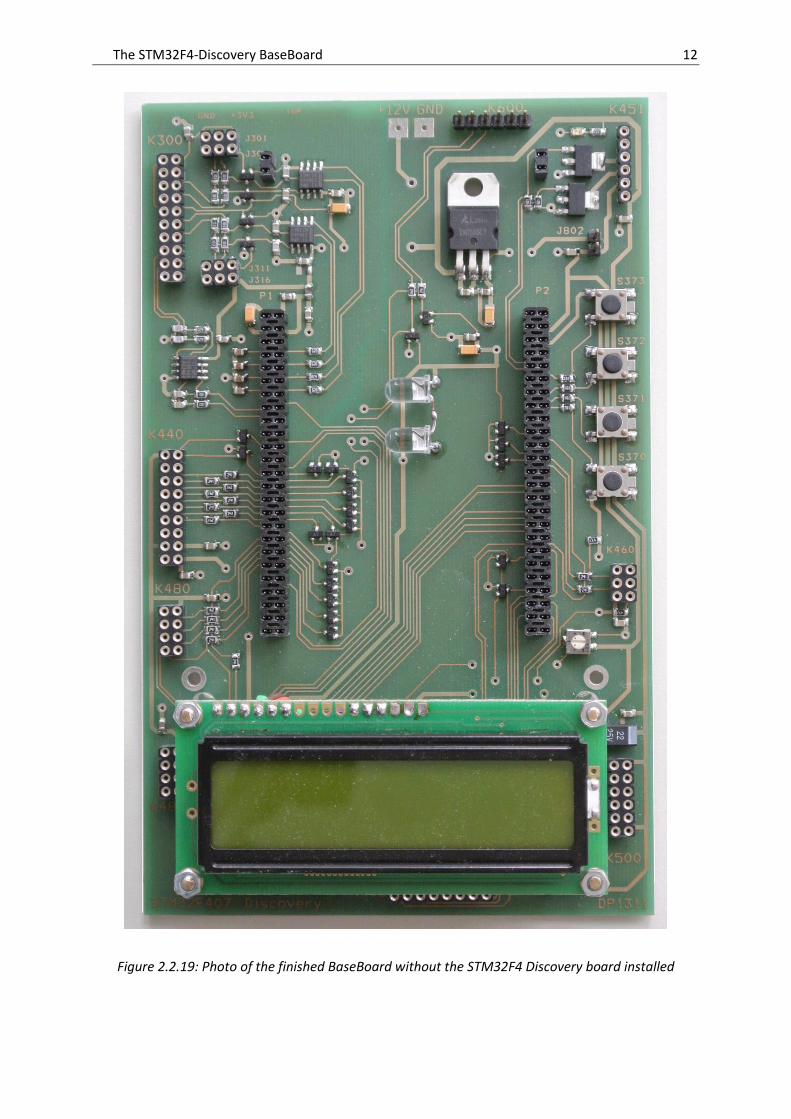
Figure 2.2.19: Photo of the finished BaseBoard without the STM32F4 Discovery board installed
The STM32F4-Discovery BaseBoard 13
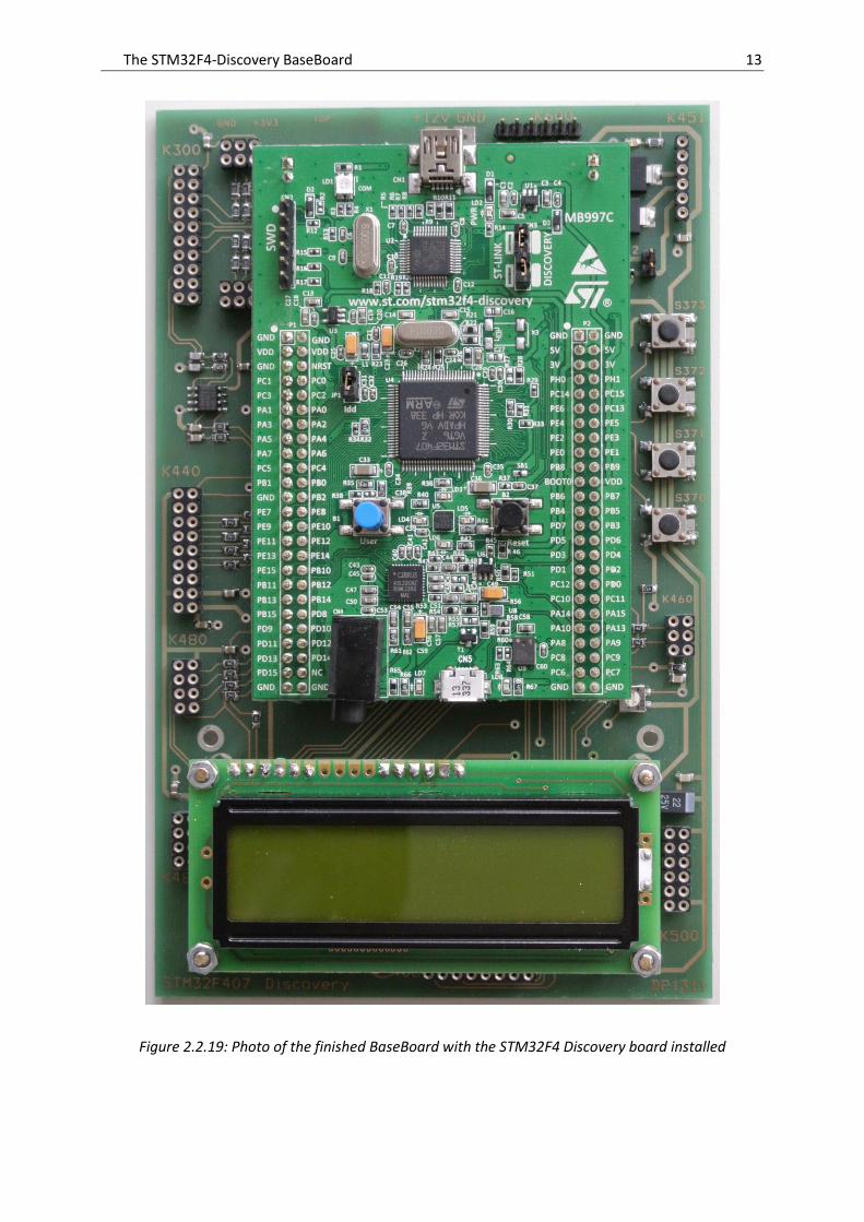
Figure 2.2.19: Photo of the finished BaseBoard with the STM32F4 Discovery board installed
Related Documents