Membranvakuumpumpe mit umschaltbarem 1-Phasen-Weitspannungsmotor Diaphragm Vacuum Pump with switchable Single Phase Wide Range Voltage Motor MVP 015-2 > P m: II= I I= II= II= R =::=_ \/A. r I II JM

Welcome message from author
This document is posted to help you gain knowledge. Please leave a comment to let me know what you think about it! Share it to your friends and learn new things together.
Transcript

Membranvakuumpumpe mit umschaltbarem 1-Phasen-Weitspannungsmotor
Diaphragm Vacuum Pump with switchable Single Phase Wide Range Voltage Motor
MVP 015-2
>
P m: II= I I= II= II= R =::=_ \/A. r I II JM
1. Sal ety Precautions "'-"""""""''""""""'"'""""""_""_lllllll"""-"''"""""!Jlllllllllll'"'-'"'lllllll1ll"'•""'51lll-.,. Read and follow all the instructions in this manual . .,. Inform yourself regarding: .,. Hazards which can be caused by the pump; nw Hazards which can arise in your system; ... Hazards which can be caused by the medium being
pumped. ... Avoid exposing any part of the body to vacuum. ... Observe all safety and accident prevention regulations . .,. Check regularly that all safety requirements are being
complied with . ... Do not carry out any unauthorised conversions or
modifications on the pump. ... When returning the pump to us please note the shipping
instructions in Section 7.
Proper use - The Diaphragm Pump MVP 015-2 may only be used forthe
purpose of generating vacuum. Do not pump corrosive or explosive gases. Do not pump liquids. Do not operate the pump in locations where there is an explosion hazard. Accessories other than those named in this manual may not be used withoutthe agreement of Pfeiffer Vacuum. Do not use the connecting line of the two-headed pump as a handle.
- The Diaphragm Pump MVP 015-2 may not be used forthe purpose of generating pressure.
1.1. For Your Orientation
Instructions in the text • Operating instructions: Here you have to do something!
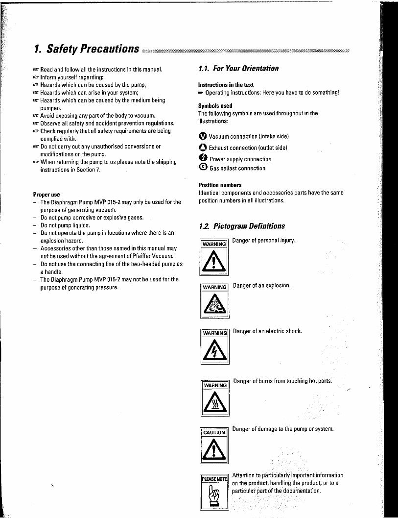
Symbols used The following symbols are used throughout in the illustrations:
(!'>Vacuum connection (intake side)
0 Exhaust connection (outlet side)
0 Power supply connection
© Gas ballast connection
Position numbers Identical components and accessories parts have the same position numbers in all illustrations.
1.2. Pictogram Definitions
WARNING Danger of personal injury.
WARNING Danger of an explosion.
WARNING Danger of an electric shock.
WARNING Danger of burns from touching hot parts.
==== Danger of damage to the pump or system. CAUTION
Attention to particularly important information on the product, handling the product, or to a particular part of the documentation.

2.1. Different Features
1 Diaphragm head 1 2 Diaphragm head 2 8 Silencer 9 Condensators
10 lnterhead connection 12 Vacuum connection 13.1 Mains swttch 13.2 Mains plug with cable 40 Gas ballast valve 48 Hollow screw V Voltage selector switch
10 40
12
v 13.1 13.2
48 9
The intake side on the front side of the pump is provided with a swivelling screw fitting IGl/8) and screw (Gl/4) tor connection to a Pfeiffer Vacuum turbopump. A pressure connection (silencer Gl/8) on the front side of the pump. Mains connection via cold unit socket with safety strap (mains cable not included in the standard version delivery consignment). ON/OFF mains switch.
3.1. Setting Up The Pump And Location • Place pump on a smooth, even surface. • Anchor the pump if it is to be erected in a stationary posi
tion. • Anchoring is not necessary if the pump is not erected in a
stationary position. • Ambienttemperature range+ 12 ... +40 °C. • Where rack installation is involved, ensure adequate
ventilation.
3.2. Connecting The Vacuum Side - Remove locking cap on intake connection. - Make connection between the vacuum system and pump
as short as possible. - Connect pump with intake connection to the apparatus.
- If liquid - which would generate vapours - is present in the system to be evacuated, a condensate trap must be fitted upstream of the pump.
3.3. Connecting The Exhaust Side CAUTION Pressure can rise to dangerous levels in exhaust
lines. Therefore, lay exhaust side lines without shut-off units. Do not connectthe exhaust side with a closed system on account of the danger
b==='- of bursting. In certain applications, exhaust gases and vapours can be very hot and represent a health and/or environment hazard. Lay lines from the pump sloping downwards so that condensate cannot run back into the pump, otherwise fit a separator.
3.4. Connecting To Mains Power The pump is driven by wide voltage AC motors with the following possible variants: 220 V- range 190 ... 260 V, 50/60 Hz 110V- range 90 ... 127V,50/60 Hz
CAUTION Power connections must comply with local regulations. Voltage and frequency information given on the rating plate must correspond to the mains voltage and frequency values. The pump may only be connected to mains current with earthed conductor.
=c=A=U=T1=0=N"" Pump versions where the thermostatic winding protection protrudes must be appropriately wired to ensure the motor is protected.
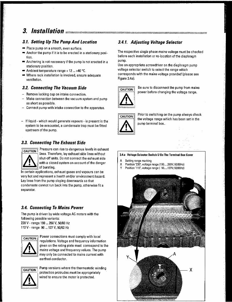
3.4.1. Adjusting Voltage Selector
The respective single phase mains voltage must be checked before each installation or re-location of the diaphragm pump. Use an appropriate screwdriver on the diaphragm pump voltage selector switch to select the range which corresponds with the mains voltage provided (please see Figure 3.4a).
CAUTION
CAUTION
Be sure to disconnectthe pump from mains power before changing the voltage range.
Prior to switching on the pump always check the voltage range which has been set in the pump terminal box ..
3.4.a Voltage Selector Switch U On The Terminal Box Cover
A Setting range marking X Position "230", voltage range (190 ..... 260V; 50/60Hz) Y Position "115", voltage range ( 90 ..... 127V; 50/60Hz)

4.1. Important Information
WARNING Before starting, ensure that impermissibly high pressures cannot build up on the pressure side. Interchanging the connections causes dangerous excess pressure levels. Do not start the pump if pressure difference between in let and outlet exceeds max. 1 bar.
Attemps to start pump at higher differential pressure may cause the motor to jam and damage may result
rr====;i When the pump is running, surfaces and motor WARNING
casing become hot.
& CAUTION
Use only ·c· version pumps where the pumping of corrosive gases is involved.
rc====o Prevent internal condensation, transfer of CAUTION
liquids or dust. The diaphragm and valves will be damaged, if liquids are pumped in significant amount over lengthy periods!
Connection with Relaisbox at TC 600 for intermittend operation
Relaisbox
4.2 Switching ON/OFF The Pump The pump can be switched on and off at all times.
CAUTION If the pump is subjected to condensates it should be allowed to run for a few minutes under atmospheric pressure before switching off.
Intermittent Operations To prolong the life of diaphragm pumps, intermittent operations can be selected with lesser gas throughputs of < 0.18 mbar l/s. This means that, dependent on the TMP power take-up, the backing pump will be switched on and off. TMP power take-up is dependent on the fore-vacuum pressure and gas throughput. - By comparing the power take-up with an upper and a
lower limit value, the relative switch-on duration with lesser gas throughputs can be reduced to approx. 1 to 60%
- To avoid too frequent switching on, the buffer volume in the fore-vacuum line should amountto? 0.5 liter from approx. 0.018 mbar l/s.
Connect diaphragm pumps in the pumping station according wiring diagram in operating instructions PT 800 030 BN of the Backing Pump Relay Boxes.
PM 041 937 GT
: ~ ~~"~ --~ j l : -~--......,.r---_..,~:{_-.... _--L.-_~..,"'"j'--_-_-_--':"';~~-,,_-~+~ .... =- ) Backing pump MVP line
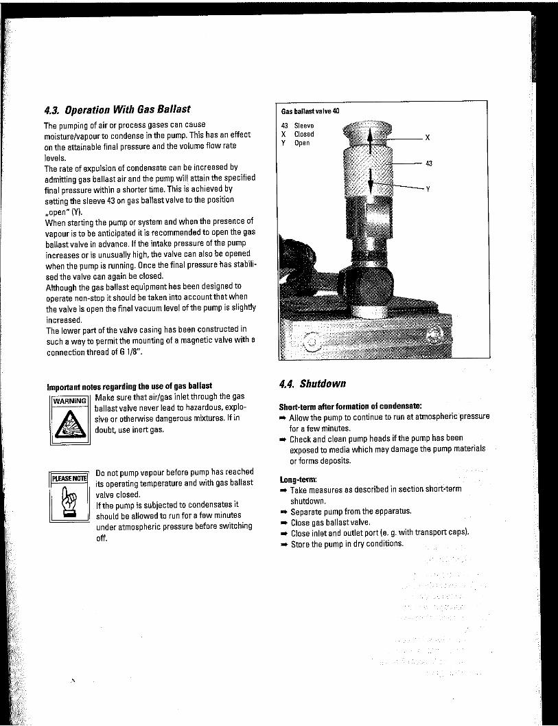
4.3. Operation With Gas Ballast The pumping of air or process gases can cause moisture/vapour to condense in the pump. This has an effect on the attainable final pressure and the volume flow rate levels. The rate of expulsion of condensate can be increased by admitting gas ballast air and the pump will attain the specified final pressure within a shorter time. This is achieved by setting the sleeve 43 on gas ballast valve to the position •• open .. (Y). When starting the pump or system and when the presence of vapour is to be anticipated it is recommended to open the gas ballast valve in advance. If the intake pressure of the pump increases or is unusually high. the valve can also be opened when the pump is running. Once the final pressure has stabilised the valve can again be closed. Although the gas ballast equipment has been designed to operate non-stop it should be taken into accountthat when the valve is open the final vacuum level of the pump is slightly increased. The lower part of the valve casing has been constructed in such a way to permit the mounting of a magnetic valve with a connection thread of G 1/8 ...
Important notes regarding the use of gas ballast WARNING Make sure that air/gas inlet through the gas
A ballast valve never lead to hazardous. explosive or otherwise dangerous mixtures. If in doubt, use inert gas.
Oo not pump vapour before pump has reached its operating temperature and with gas ballast valve closed. If the pump is subjected to condensates it should be allowed to run for a few minutes under atmospheric pressure before switching off.
Gas ballast valve 40
43 Sleeve X Closed Y Open
---43
y
4.4. Shutdown
Short-term after formation of condensate: • Allow the pump to continue to run at atmospheric pressure
for a few minutes. • Check and clean pump heads ifthe pump has been
exposed to media which may damage the pump materials or forms deposits.
Long-term: • Take measures as described in section short-term
shutdown. • Separate pump from the apparatus. • Close gas ballast valve. • Close inlet and outlet port (e.g. with transport caps). • Store the pump in dry conditions.
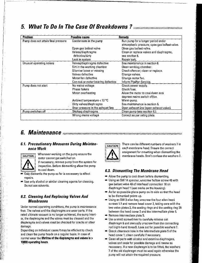
5. What To Do In The Case Of Breakdowns ? lllllllll!lmlUITTJllll,!llllliill'"llll"-""""'--'allll'""lll''
Problem Pump does not attain final pressure
Possible cause Condensate in the pump
Open gas ballast valve Valves/diaphragms defective/dirty
Leak ins stem
Rema Run pump for a longer period under atmospheric pressure; open gas ballast valve. Close gas ballast valve. Clean or replace valves and diaphragms, see section 6. Re air leak.
Unusual operating noises Valves/diaphragms defective Dirt in the working chamber Silencer loose or missing Valves defective
See maintenance in section 6. Clean working chamber. Check silencer; clean or replace. Change valves.
Motor fan defective Change motor fan. Con-rod or motor bearin defective Inform Pfeiffer-Service.
Pump does not start No mains voltage Phase failure Motor overheating
Pum switches off
6.1. Precautionary Measures During Maintenance Work
CAUTION Whenever working on the pump ensure the motor cannot get switched on. If necessary, remove pump from the system for inspection. Before dismantling allow the pump to cool down.
• Only dismantle the pump as far is necessary to effect repairs.
• Use only alcohol or similar cleaning agents for cleaning. Do not use solvents.
6.2. Cleaning And Replacing Valves And Membranes
Under normal operating conditions, the pump is maintenance free. The valves and the diaphragms are wear parts. If the rated ultimate vacuum is no longer achieved, the pump interior, the diaphragms and the valves must be cleaned and the diaphragms and valves must be checked for cracks or other damage. Depending on individual cases it may be efficientto check and clean the pump heads on a regular basis. In case of normal wear the lifetime of the diaphragms and valves is> 10000 operating hours. '
CAUTION
Check power supply. Check fuse. Allow the motor to cool down and depress mains switch off/on. Warm pump. See maintenance in section 6. 0 en exhaust line (o en exhaust valve).
Correct as per rating plate.
There can be different numbers of washers 7 in each membrane head. Ensure the correct assignment for mounting when dismantling the membrane heads. Don't confuse the washers 7.
6.3. Dismantling The Membrane Head • Allow the pump to cool down before dismantling. • Using an SW 14 spanner, unscrew hollow screw 48 with
gas ballast valve 40 of interhead connection 10 on diaphragm head 1 (see marks on the housing).
•As far as possible place pump on its side so thatthe head to be dismantled points up.
• Using an SW 3 alien key, unscrew the four alien head screws 1.1 and remove head cover 2, taking care with the two valve plates 3, the sealing rings and the sealing ring 39 between the head cover 2 and the intermediate plate 5.
• Remove intermediate plate 5. • Use a small screwdriver to carefully release out
diaphragm 6 and manually unscrew from the connecting rod (right-hand thread). Look out for possible washers 7.
• Check clearance hole in the intermediate plate 5 of the head cover 1; clean carefully if necessary.
• Clean all parts with alcohol and examine diaphragms, valves and seals for possible damage and renew as necessary. If a new diaphragm is to be fitted, the washers 7 of the old diaphragm must be used again otherwise the pump will not attain the required pressure.
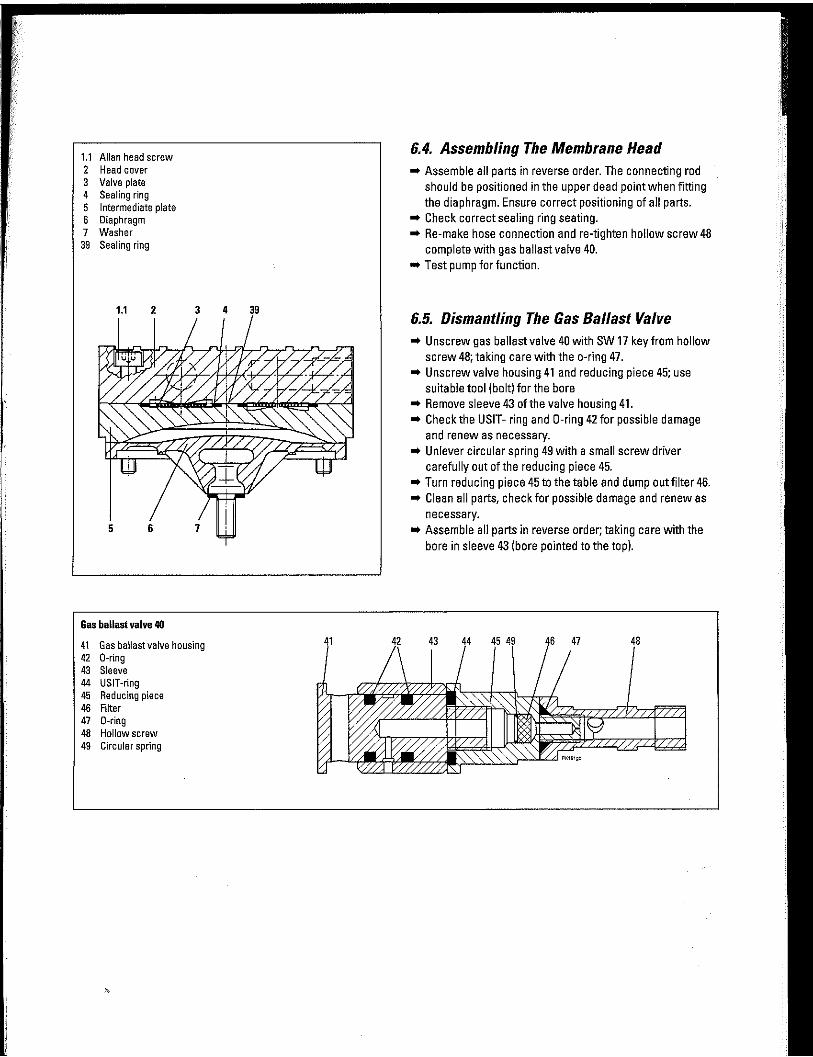
1.1 Allan head screw 2 Head cover 3 Valve plate 4 Sealing ring 5 Intermediate plate 6 Diaphragm 7 Washer
39 Sealing ring
1.1 2 3
Gas ballast valve 40
41 Gas ballast valve housing 42 0-ring 43 Sleeve 44 USIT-ring 45 Reducing piece 46 Filter 47 0-ring 48 Hollow screw 49 Circular spring
4 39
41 42
6.4. Assembling The Membrane Head • Assemble all parts in reverse order. The connecting rod
should be positioned in the upper dead point when fitting the diaphragm. Ensure correct positioning of all parts.
• Check correct sealing ring seating. • Re-make hose connection and re-tighten hollow screw 48
complete with gas ballast valve 40. • Test pump for function.
6.5. Dismantling The Gas Ballast Valve • Unscrew gas ballast valve 40 with SW 17 key from hollow
screw 48; taking care with the a-ring 47. • Unscrew valve housing 41 and reducing piece 45; use
suitable tool (bolt) for the bore • Remove sleeve 43 of the valve housing 41. • Check the USIT- ring and 0-ring 42 for possible damage
and renew as necessary. • Unlever circular spring 49 with a small screw driver
carefully out of the reducing piece 45. • Turn reducing piece 45 to the table and dump outfilter 46. • Clean all parts. check for possible damage and renew as
necessary. • Assemble all parts in reverse order; taking care with the
bore in sleeve 43 (bore pointed to the top).
43 44 45 49 46 47 48
Do Make Use Of Our Service Facilities In the event that repairs are necessary to your pumping station, a number of options are available to you to ensure any system down time is keptto a minimum: - Have the pump repaired on the spot by our Pfeiffer
Vacuum Service Engineers; - Return the individual components to the manufacturer for
repairs; - Replace individual components with a new value
exchange units. Local Pfeiffer Vacuum representatives can provide full
details.
Before Returning: • When returning the pump please use original factory
packing. • Dismantle all accessories. • lithe pump is free of harmful substances, please attach a
clearly visible notice: "Free of contamination" (to the unit being returned, the delivery note and accompanying
paperwork). Harmful substances" are substances and preparations as defined in current legislation. Pfeiffer Vacuum will carry out the decontamination and invoice this work to you if you have not attached this note. This also applies where the operator does not have the facilities to carry outthe decontamination work. Units which are contaminated microbiologically, explosively or radioactively cannot be accepted as a matter of
principle.
Fill Out The Contamination Declaration • In every case the "Contamination Declaration" must be
completed diligently and truthfully. • A copy of the completed declaration must accompany the
unit; any additional copies must be sent to your local Pfeif
fer Vacuum Service Center. Please get in touch with your local Pleiffer Vacuum representatives if there are any questions regarding contamination.
WARNING Decontaminate units before returning or possible disposal. Do not return any units which are microbiologically, explosively or radioactively contaminated.
Returning Contaminated Units If contaminated units have to be returned for maintenance/repair, the following instructions concerning shipping must be followed without fail: • Neutralise the pump by flushing with nitrogen or dry air.
• Seal all openings to the air. • Seal pump or unit in suitable protective foil.
, • Ship units only in appropriate transport containers.
~ Repair orders are carried out according to our
~ ''"'"' ""°'""'. "'"'"" ~"''
• If repairs are necessary, please send the unit together with a short damage description to your nearest Pfeiffer
Vacuum Service Center.
----------- --- ----
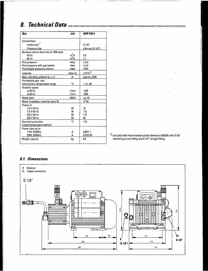
8. Tech n i ca I O ata "' ____ ,MllJJ _____ ""'llJJ"''"'"'"''-"'"'"""'"'lll•"''."''"'oo"""''lllllllDTI•--""' Size Untt
Connections Intake side
11
Pressure side Nominal volume flow rate at 1000 mbar
50 Hz m3/h 60 Hz m3/h
Final pressure mbar Final pressure with gas ballast mbar Permissible exhaust_messure mbar
Leakrate mbar l/s Max. ~ratiri..g_altitude (a. s. !1 m Permissible gas- and environment te~rature ra!:!fill oc Rotation speed
at 50 Hz 1/min at 60 Hz 1/min
Noise level dBIAI Motor (insulation material class B)
Power at 115V50Hz w 115V60Hz w 230 V60 Hz w 230V50Hz w
Overload protection oc (coiled ten:rn_1:irature switch) Power take-up at
115V, 50/60Hz A 230V, 50/60Hz A
Weight, approx. kg
8.1. Dimensions
8 Silencer 12 Intake connection
G 1/4"
MVP015-2
G 1/8" silencer (G 1/8")
0.9 1.1 ~3,5
:::; 4,5 1050
~ 5-10-3
1'1!.E!OX. 2000
+ 12 .. .40
1500 1800 ca.52 IP 54
75 115 110 65 118
0,65/1,1 0,35/0,55 6,5
Z65
2ffl
1) included with hose (inside/outside dimension 06/08) with Gl/8' swivelling screw fitting and G 1/4" straight fitting
' 1 .. 116 • 8
(G 1/8") i-~-----140
----
\ 12
G 1/8"
170
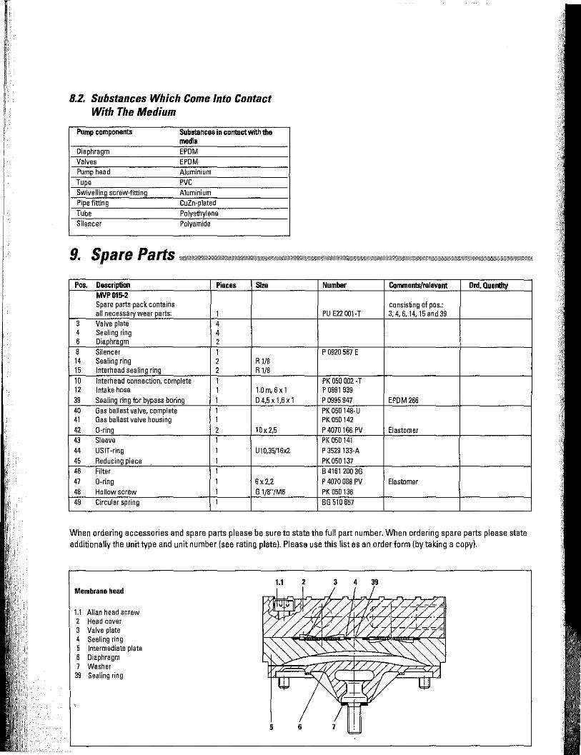
8.2. Substances Which Come Into Contact With The Medium
Pump components Substances in contact with the media
Diaphragm EPDM Valves EPDM Pump head Aluminium Tupe PVC Swivelling screw-fitting Aluminium Pipe fitting CuZn-plated Tube Polyethylene Silencer Polyamide
Pos. Description Pieces Size MVP015-2 Spare parts pack contains all necessary wear parts: 1
3 Valve plate 4 4 Sealing ring 4 6 Diaphragm 2 8 Silencer 1 14 Sealing ring 2 R 1/8 15 lnterhead sealing ring 2 R 1/8 10 lnterhead connection, complete 1 12 Intake hose 1 1.0rn,6x1 39 Sealing ring for bypass boring 1 D4,5x1,6x1 40 Gas ballast valve, complete 1 41 Gas ballast valve housing 1 42 0-ring 2 10 x 2,5 43 Sleeve 1 44 USIT-ring 1 u 10,35/16x2 45 Reducing piece 1 46 Filter 1 47 0-ring 1 6x2,2 48 Hollow screw 1 G 1/8"/M6 49 Circular spring 1
Number Comments/relevant Ord. Quantity
consisting of pas.: PU E22 001·T 3, 4, 6, 14, 15 and 39
P 0920 567 E
PK 050 002 -T p 0991 939 p 0995 947 EPDM 266 PK050148-U PK050142 P 4070166 PV Elastomer PK 050141 P 3529 133-A PK050137 B 41612003G P 4070 088 PV Elastomer PK 050136 BG 510 857
When ordering accessories and spare parts please be sure to state the full part number. When ordering spare parts please state additionally the unit type and unit number (see rating plate). Please use this list as an order form (by taking a copy).
Membrane head
1.1 Allan head screw 2 Head cover 3 Valve plate 4 Sealing ring 5 Intermediate plate 6 Diaphragm 7 Washer
39 Sealing ring
1.1 2 3 4 39

Gas ballast valve 40
41 Gas ballast valve housing 42 0-ring 43 Sleeve 44 USIT-ring 45 Reducing piece 46 Filter 47 0-ring 48 Hollow screw 49 Circular spring
Pos. Description Mains cable for wiring (without plug) Mains cable 230 V with schuko plug, EURO Counter plug CEE 22
Mains cable 1t5V, UL EURO Counter plug CEE 22
Small flange for intake or outlet side Relay box for TC 600 connection Screw in flange with female thread
Hose connection DN 6 x 400 mm for the intake side
41
Pieces 1
1
1
1
42 43 44 45 49 46 47 48
Size Number Comments Order Quantity 3.0 m P 4564 309-ZH
3.0 m P 4564 309-ZA
3.0 m P 4564 309-ZE
ON 16 ISO-KF PK050108-T
PM 041 937 GT G 1/4" I PM 006 994 ON 16 ISO-KF G 1/8" and G 1/4" PO 920 739 E with straight fitting
and sealing rings

Declaration of Contamination of Vacuum Equipment and Components
The repair and/or service of vacuum components will only be carried out if a correctly completed declaration has been submitted. Non-completion will result in delay.
The manufacturer could refuse to accept any equipment without a declaration.
This declaration can only be completed and signed by authorised and qualified staff:
1. Description of component:
- Equipment type/model:----------
-Code No.:
- Serial No.:
- Invoice No.:
- Delivery Date:
3. Equipment condition
- Has the equipment been used?
yes 0 noO
-What type of pump oil was used?
- Is the equipment free from potentially harmful substances?
yes 0 no 0
(go to section 5) (go to section 4)
2. Reason lorreturn:
4. Process related contamination
of equipment
- toxic yesO noO
- corrosive yesO noO
- microbiological hazard*) yesO noO
- explosive*) yesO noO
- radioactive*) yesO noO
- other harmful substances yesO noO
*) We will not accept delivery of any equipmentthat has been radioactively or microbiologically contaminated without written evidence of decontamination!
Please list all substances, gases and by-products which may have come into contact with the equipment:
Tradename Chemical name Danger class Precautions associated Action if spillage or human Product name (or Symbol) with substance contact Manufacturer
1.
2.
3.
4.
5.
5. Legally Binding Declaration
I hereby declare thatthe information supplied on this form is complete and accurate. The despatch of equipment will be in accordance with the appropriate regulations covering Packaging, Transportation and Labelling of Dangerous Substances.
Name of Organisation: -------------------------------Address: Post code:---------------
Tel.:
Fax: Telex: -----------------Name:
Job title:
Date: Company stamp: -------------Legally binding signature: _______________________________ _
Related Documents