Software Manual LB device All models Revision 1.1

Welcome message from author
This document is posted to help you gain knowledge. Please leave a comment to let me know what you think about it! Share it to your friends and learn new things together.
Transcript
Software Manual
LB device
All models Revision 1.1
1
Table Of Contents
1. INTRODUCTION------------------------------------------------------------------------------------------1
2. THEORY-----------------------------------------------------------------------------------------------------2 2.1. Overview-----------------------------------------------------------------------------------------------2 2.2. Background Information --------------------------------------------------------------------------3 2.3. Theory of LB Measurements----------------------------------------------------------------------6 2.4. Further Reading ----------------------------------------------------------------------------------- 12
3. LAYERBUILDER --------------------------------------------------------------------------------------- 13 3.1. Connections ----------------------------------------------------------------------------------------- 14
4. SOFTWARE---------------------------------------------------------------------------------------------- 15 4.1. Overview--------------------------------------------------------------------------------------------- 15 4.2. LB Control Software------------------------------------------------------------------------------ 18 4.3. Device Parameters--------------------------------------------------------------------------------- 20 4.4. Calibration ------------------------------------------------------------------------------------------ 25 4.5. Control Panel --------------------------------------------------------------------------------------- 27
5. PRELIMINARIES --------------------------------------------------------------------------------------- 31 5.1. Experimental Setup ------------------------------------------------------------------------------- 31 5.2. The Database --------------------------------------------------------------------------------------- 33 5.3. Cleaning --------------------------------------------------------------------------------------------- 35 5.4. Placing the surfactant----------------------------------------------------------------------------- 35
6. EXPERIMENTS ----------------------------------------------------------------------------------------- 36 6.1. Overview--------------------------------------------------------------------------------------------- 36 6.2. Trough Controls ----------------------------------------------------------------------------------- 37 6.3. Dipper Controls ------------------------------------------------------------------------------------ 40 6.4. Compression Isotherm Measurement --------------------------------------------------------- 45 6.5. Dipping Experiment------------------------------------------------------------------------------- 48 6.6. Alternate Dipping Experiment------------------------------------------------------------------ 50
7. DATA REDUCTION AND ANALYSIS ------------------------------------------------------------ 52 7.1. Overview--------------------------------------------------------------------------------------------- 52 7.2. Locating an Experiment-------------------------------------------------------------------------- 53 7.3. Data Analysis --------------------------------------------------------------------------------------- 54 7.4. Exporting Data ------------------------------------------------------------------------------------- 57
8. OSCILLATING BARRIERS -------------------------------------------------------------------------- 61
9. CONTACT INFORMATION -------------------------------------------------------------------------- 64

0
APPENDIX A. QUICK START GUIDE------------------------------------------------------------------ 65
APPENDIX B. EXAMPLE ISOTHERM EXPERIMENTS ------------------------------------------- 71
APPENDIX C. EXAMPLE DIPPING EXPERIMENT------------------------------------------------- 79
APPENDIX D. OTHER INTERESTING EXPERIMENTS------------------------------------------- 85
APPENDIX E. PAPER WILHELMY PLATES --------------------------------------------------------- 87

1
1. Introduction The Langmuir and Langmuir-Blodgett (LB) devices available from KSV Instruments are efficient and effective in investigating floating monolayers, precise deposition of multilayers onto solid substrates or simply as platforms for use in observing surface chemistry effects such as the breakdown of an enzyme or the crystalline structure of a surfactant. The wide range of available systems and the many modules available make customization a charm, and if the troughs available do not suit your needs then contact us about designing a particular trough to your specifications. To avoid confusion this manual the refers to just LB measurements, though Langmuir, Langmuir-Schaefer, compression/relaxation isotherms, monolayer kinetics analysis and many other experiment types can be operated. There are four series of LB systems available today, the KSV 5000, 2000, Minitrough and the Minimicro in descending order of size. The differences between the systems are mechanical, i.e. the same software and interface unit operates all of the LB devices. KSV 2000 is the basic multipurpose LB device. KSV 5000 adds a sturdy frame with automatic elevator arms for attaching additional measurement devices, becoming the most versatile LB device available today. The KSV Minitrough is a more compact and economical LB device. The KSV Minimicro is a small and elegant LB device brilliant for depositions on small substrates or to minimize sample volumes. This is the software manual for all of the LB devices, featuring instructions on how to run the experiments, how to analyze the data and the basics of the theory behind the measurements. Make sure to check the device-specific manual for details such as physical description, cleaning and the procedures necessary for running the experiments. If any problem would appear for the product, then please contact KSV Instrument Ltd´s support department at [email protected] or contact a local distributor. For further information and for the contact details of the nearest distributor, please visit our website at www.ksvltd.com.
2
2. Theory 2.1. Overview A) Introduction Monolayers, thin organic films of a thickness of just one molecule are the source of high expectations as useful components in many practical and commercial applications such as sensors, detectors, displays and electronic circuit components. With both the possibility to synthesize custom organic molecules and sophisticated thin film deposition technology it is possible to create electrically, optically and biologically active components on a nanometer scale. A thin organic film can be deposited on a solid substrate by various techniques. These include thermal evaporation, sputtering, electrodeposition, molecular beam epitaxy, adsorption from solution, Langmuir-Blodgett technique and self-assembly. The Langmuir-Blodgett (LB) technique is one of the most promising methods for the preparation of thin films as it enables (A) precise control of the monolayer thickness, (B) homogeneous deposition of the monolayer over large areas and (C) the possibility to make multilayer structures with varying layer composition. An additional advantage of the LB technique is that monolayers can be deposited on almost any kind of solid substrate.
B) Short History of LB-films The American statesman and scientist Benjamin Franklin began the history of Langmuir-Blodgett films. In 1774 he reported the following to the British Royal Society. "At length at Clapman where there is, on the common, a large pond, which I observed to be one day very rough with the wind, I fetched out a cruet of oil, and dropped a little of it on the water. I saw it spread itself with surprising swiftness upon the surface.. the oil, though not more than a teaspoonful, produced an instant calm over a space several yards square, which spread amazingly and extended itself gradually until it reached the leeside, making all that quarter of the pond, perhaps half an acre, as smooth as a looking glass." Had Franklin made some simple quantitative calculations he would have found out that if a teaspoonful (2 ml) of oil is spread over an area of half an acre, the thickness of the film on the surface of water must be less than 2 nm. It was not until over a hundred years later that Lord Rayleigh suspected that the maximum extension of an oil film on water represents a layer one molecule thick. At the same time the foundation for the ability to characterize monolayers on an air-water interface was set by a German woman called Agnes Pockles. She developed a rudimentary surface balance in her kitchen sink, which she used to determine (water) surface contamination as a function of area of the surface for different oils. Publication of Pockels´s work in 1891 set the stage for Langmuir's quantitative work on fatty acid, ester and alcohol monolayers.
3
Irving Langmuir was the first to perform systematic studies on floating monolayers on water in the late 1910's and early 1920's. These studies led to him being awarded the Nobel prize. As early as 1920 he reported the transfer of fatty acid molecules from water surfaces onto solid supports. However, the first detailed description of sequential monolayer transfer was given several years later by Katherine Blodgett. These built-up monolayer assemblies are therefore referred to as Langmuir-Blodgett (LB) films. The term Langmuir film is normally reserved for a floating monolayer. After the pioneering work done by Langmuir and Blodgett it took almost half a century before scientists all around the world started to realize the opportunities of this unique technique. The first international conference on LB films was held in 1979 and since then the use of this technique has been increasing widely among scientists working on various different fields of research. Today, we are in a situation where the production of nanoscale organic films with the LB method has slowly started to find possible practical applications in many fields. However, even though the ideas for practical applications are growing the L and LB films are still mostly used as model systems for example for biomembrane research and multilayer coatings.
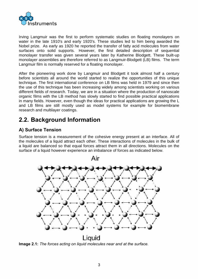
2.2. Background Information A) Surface Tension Surface tension is a measurement of the cohesive energy present at an interface. All of the molecules of a liquid attract each other. These interactions of molecules in the bulk of a liquid are balanced so that equal forces attract them in all directions. Molecules on the surface of a liquid however experience an imbalance of forces as indicated below.
Image 2.1: The forces acting on liquid molecules near and at the surface.
4
The excess energy present at the surface is called surface free energy and can be quantified as a measurement of energy/area. It is also possible to describe this situation as having a line tension or a surface tension which is quantified as a force / length measurement. The most common units for surface tension are dynes/cm or mN/m. These units are equivalent. The surface is the interface of two fluids. The experiment is referred to as a surface tension measurement if it involves a gaseous phase. If two liquids are tested then the experiment is referred to as an interfacial tension measurement. In either case the denser fluid is referred to as the heavy phase and the less dense fluid is referred to as the light phase. Solids also may be described to have a surface free energy at their interfaces but direct measurement of its value is not possible through the techniques used for liquids. Polar liquids like water have strong intermolecular interactions and thus have high surface tension. Any factor which decreases the strength of the interaction will lower the surface tension, and so an increase to the temperature of the system will lower surface tension. Any contamination, especially by surfactants, will lower surface tension which is why researchers should be very concerned about cleanliness and preventing contaminants!
B) Surfactants
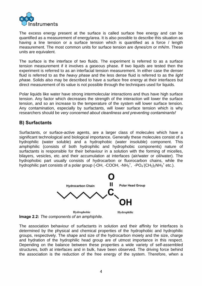
Surfactants, or surface-active agents, are a larger class of molecules which have a significant technological and biological importance. Generally these molecules consist of a hydrophilic (water soluble) and a hydrophobic (water insoluble) component. This amphiphilic (consists of both hydrophilic and hydrophobic components) nature of surfactants is responsible for their behaviour in a solution with the forming of micelles, bilayers, vesicles, etc. and their accumulation at interfaces (air/water or oil/water). The hydrophobic part usually consists of hydrocarbon or fluorocarbon chains, while the hydrophilic part consists of a polar group (-OH, -COOH, -NH3
+, -PO4-(CH2)2NH3
+ etc.).
Image 2.2: The components of an amphiphile. The association behaviour of surfactants in solution and their affinity for interfaces is determined by the physical and chemical properties of the hydrophobic and hydrophilic groups, respectively. The shape and size of the hydrocarbon moiety and the size, charge and hydration of the hydrophilic head group are of utmost importance in this respect. Depending on the balance between these properties a wide variety of self-assembled structures, both at interfaces and in bulk, have been observed. The driving force behind the association is the reduction of the free energy of the system. Therefore, when a
5
surfactant comes in contact with water it accumulates at the air/water interface causing a decrease in the surface tension of water.
C) Insoluble monolayers
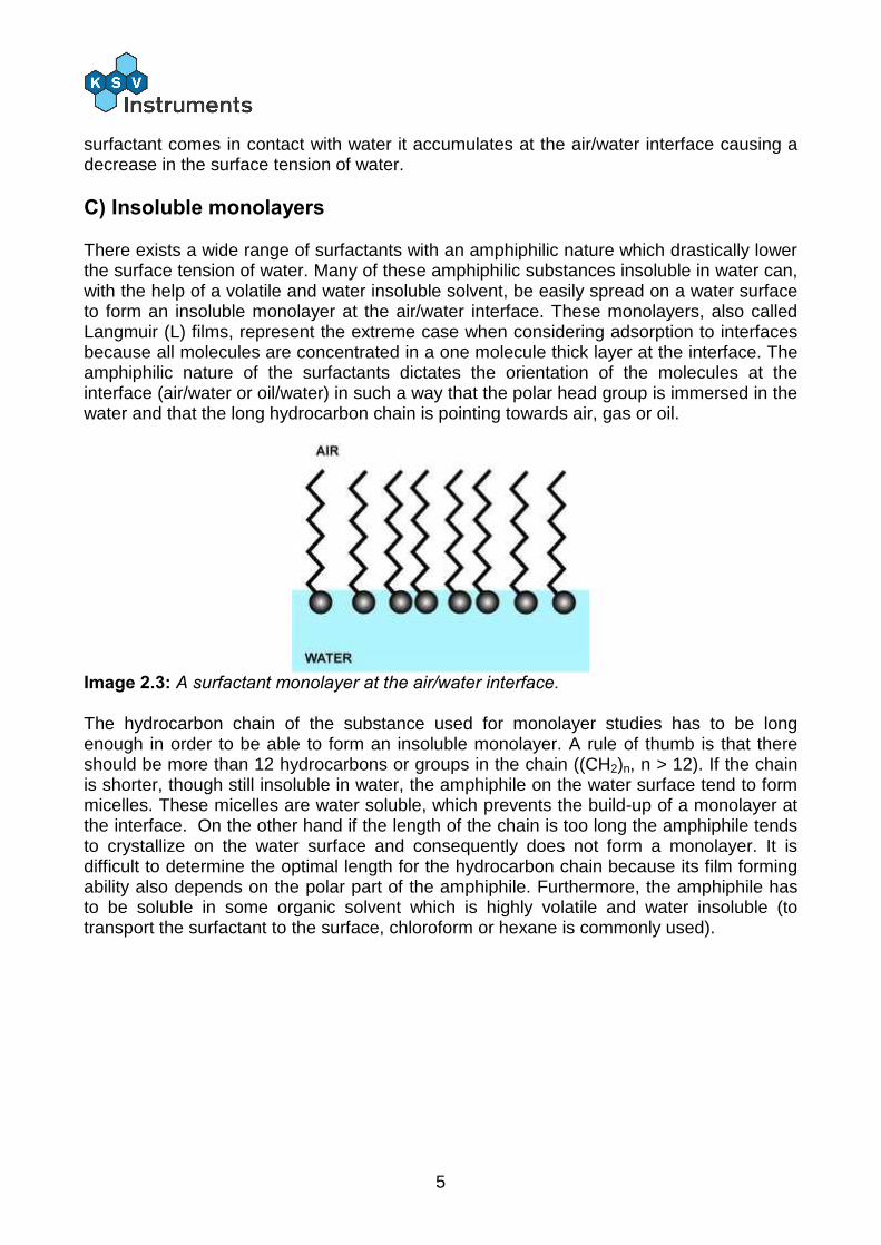
There exists a wide range of surfactants with an amphiphilic nature which drastically lower the surface tension of water. Many of these amphiphilic substances insoluble in water can, with the help of a volatile and water insoluble solvent, be easily spread on a water surface to form an insoluble monolayer at the air/water interface. These monolayers, also called Langmuir (L) films, represent the extreme case when considering adsorption to interfaces because all molecules are concentrated in a one molecule thick layer at the interface. The amphiphilic nature of the surfactants dictates the orientation of the molecules at the interface (air/water or oil/water) in such a way that the polar head group is immersed in the water and that the long hydrocarbon chain is pointing towards air, gas or oil.
Image 2.3: A surfactant monolayer at the air/water interface. The hydrocarbon chain of the substance used for monolayer studies has to be long enough in order to be able to form an insoluble monolayer. A rule of thumb is that there should be more than 12 hydrocarbons or groups in the chain ((CH2)n, n > 12). If the chain is shorter, though still insoluble in water, the amphiphile on the water surface tend to form micelles. These micelles are water soluble, which prevents the build-up of a monolayer at the interface. On the other hand if the length of the chain is too long the amphiphile tends to crystallize on the water surface and consequently does not form a monolayer. It is difficult to determine the optimal length for the hydrocarbon chain because its film forming ability also depends on the polar part of the amphiphile. Furthermore, the amphiphile has to be soluble in some organic solvent which is highly volatile and water insoluble (to transport the surfactant to the surface, chloroform or hexane is commonly used).
6
2.3. Theory of LB Measurements
A) Surface Pressure
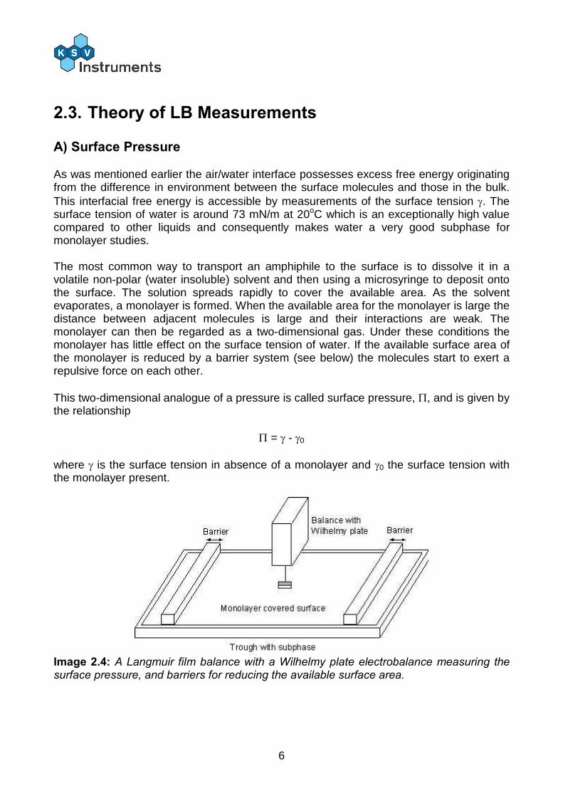
As was mentioned earlier the air/water interface possesses excess free energy originating from the difference in environment between the surface molecules and those in the bulk. This interfacial free energy is accessible by measurements of the surface tension . The surface tension of water is around 73 mN/m at 20oC which is an exceptionally high value compared to other liquids and consequently makes water a very good subphase for monolayer studies. The most common way to transport an amphiphile to the surface is to dissolve it in a volatile non-polar (water insoluble) solvent and then using a microsyringe to deposit onto the surface. The solution spreads rapidly to cover the available area. As the solvent evaporates, a monolayer is formed. When the available area for the monolayer is large the distance between adjacent molecules is large and their interactions are weak. The monolayer can then be regarded as a two-dimensional gas. Under these conditions the monolayer has little effect on the surface tension of water. If the available surface area of the monolayer is reduced by a barrier system (see below) the molecules start to exert a repulsive force on each other. This two-dimensional analogue of a pressure is called surface pressure, , and is given by the relationship
= - 0 where is the surface tension in absence of a monolayer and 0 the surface tension with the monolayer present.
Image 2.4: A Langmuir film balance with a Wilhelmy plate electrobalance measuring the surface pressure, and barriers for reducing the available surface area.
7
B) The Langmuir Film Balance
The trough holding the subphase is usually made of Teflon to prevent any leakage of the subphase over the edges. The trough is thermostated by circulating water in channels placed underneath the teflon trough. The surface area of the trough can be varied by sweeping movable barriers over the surface of the trough. The barriers are made of Delrin, a hydrophilic material, and heavy enough to prevent any leakage of the monolayer beneath the barrier. The surface pressure and the mean molecular area are continuously monitored during the compression. The mean molecular area can be determined by monitoring the distance the barriers have moved and with the known dimensions of the trough. The surface pressure is measured by the Wilhelmy plate-method. In this method a measurement is made by determining the force due to surface tension on a plate suspended so that it is partially immersed in the subphase (see below). This force is then converted into surface tension (mN/m or dynes/cm) with the help of the dimensions of the plate.
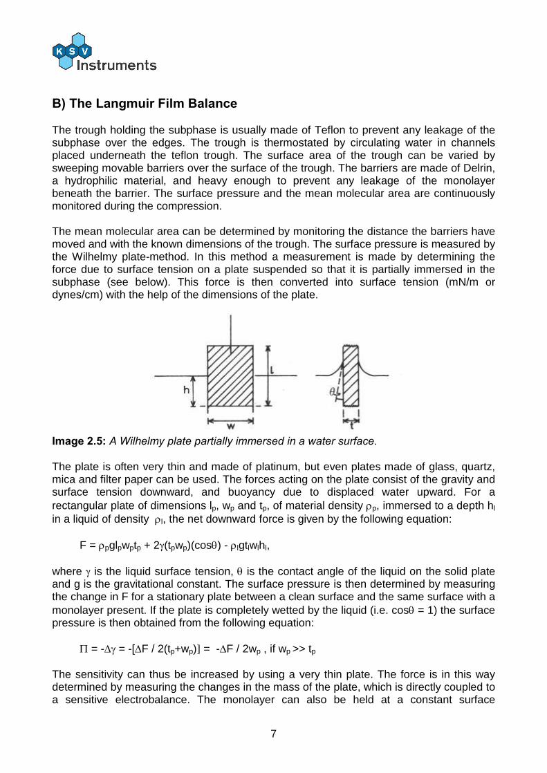
Image 2.5: A Wilhelmy plate partially immersed in a water surface. The plate is often very thin and made of platinum, but even plates made of glass, quartz, mica and filter paper can be used. The forces acting on the plate consist of the gravity and surface tension downward, and buoyancy due to displaced water upward. For a rectangular plate of dimensions lp, wp and tp, of material density p, immersed to a depth hl in a liquid of density l, the net downward force is given by the following equation:
F = pglpwptp + 2(tpwp)(cos) - lgtlwlhl, where is the liquid surface tension, is the contact angle of the liquid on the solid plate and g is the gravitational constant. The surface pressure is then determined by measuring the change in F for a stationary plate between a clean surface and the same surface with a monolayer present. If the plate is completely wetted by the liquid (i.e. cos = 1) the surface pressure is then obtained from the following equation:
= - = -[F / 2(tp+wp)] = -F / 2wp , if wp >> tp The sensitivity can thus be increased by using a very thin plate. The force is in this way determined by measuring the changes in the mass of the plate, which is directly coupled to a sensitive electrobalance. The monolayer can also be held at a constant surface
8
pressure, which is a computer enabled controlled feedback system between the electrobalance and the motor responsible for the movements of the compressing barrier. This is useful when producing LB films i.e. when the monolayer is deposited on a solid substrate. There are even other ways to control the area of the monolayer and to measure the surface pressure but the constructions above are the most commonly used.
C) Surface Pressure Against Mean Molecular Area Isotherms
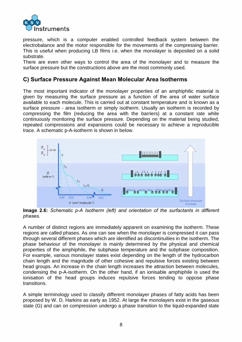
The most important indicator of the monolayer properties of an amphiphilic material is given by measuring the surface pressure as a function of the area of water surface available to each molecule. This is carried out at constant temperature and is known as a surface pressure - area isotherm or simply isotherm. Usually an isotherm is recorded by compressing the film (reducing the area with the barriers) at a constant rate while continuously monitoring the surface pressure. Depending on the material being studied, repeated compressions and expansions could be necessary to achieve a reproducible trace. A schematic p-A-isotherm is shown in below.
Image 2.6: Schematic p-A Isotherm (left) and orientation of the surfactants in different phases. A number of distinct regions are immediately apparent on examining the isotherm. These regions are called phases. As one can see when the monolayer is compressed it can pass through several different phases which are identified as discontinuities in the isotherm. The phase behaviour of the monolayer is mainly determined by the physical and chemical properties of the amphiphile, the subphase temperature and the subphase composition. For example, various monolayer states exist depending on the length of the hydrocarbon chain length and the magnitude of other cohesive and repulsive forces existing between head groups. An increase in the chain length increases the attraction between molecules, condensing the p-A-isotherm. On the other hand, if an ionisable amphiphile is used the ionisation of the head groups induces repulsive forces tending to oppose phase transitions. A simple terminology used to classify different monolayer phases of fatty acids has been proposed by W. D. Harkins as early as 1952. At large the monolayers exist in the gaseous state (G) and can on compression undergo a phase transition to the liquid-expanded state
9
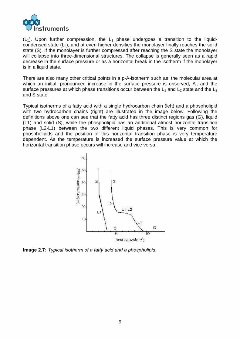
(L1). Upon further compression, the L1 phase undergoes a transition to the liquid-condensed state (L2), and at even higher densities the monolayer finally reaches the solid state (S). If the monolayer is further compressed after reaching the S state the monolayer will collapse into three-dimensional structures. The collapse is generally seen as a rapid decrease in the surface pressure or as a horizontal break in the isotherm if the monolayer is in a liquid state. There are also many other critical points in a p-A-isotherm such as the molecular area at which an initial, pronounced increase in the surface pressure is observed, Ai, and the surface pressures at which phase transitions occur between the L1 and L2 state and the L2 and S state. Typical isotherms of a fatty acid with a single hydrocarbon chain (left) and a phospholipid with two hydrocarbon chains (right) are illustrated in the image below. Following the definitions above one can see that the fatty acid has three distinct regions gas (G), liquid (L1) and solid (S), while the phospholipid has an additional almost horizontal transition phase (L2-L1) between the two different liquid phases. This is very common for phospholipids and the position of this horizontal transition phase is very temperature dependent. As the temperature is increased the surface pressure value at which the horizontal transition phase occurs will increase and vice versa.
Image 2.7: Typical isotherm of a fatty acid and a phospholipid.
10
D) Deposition
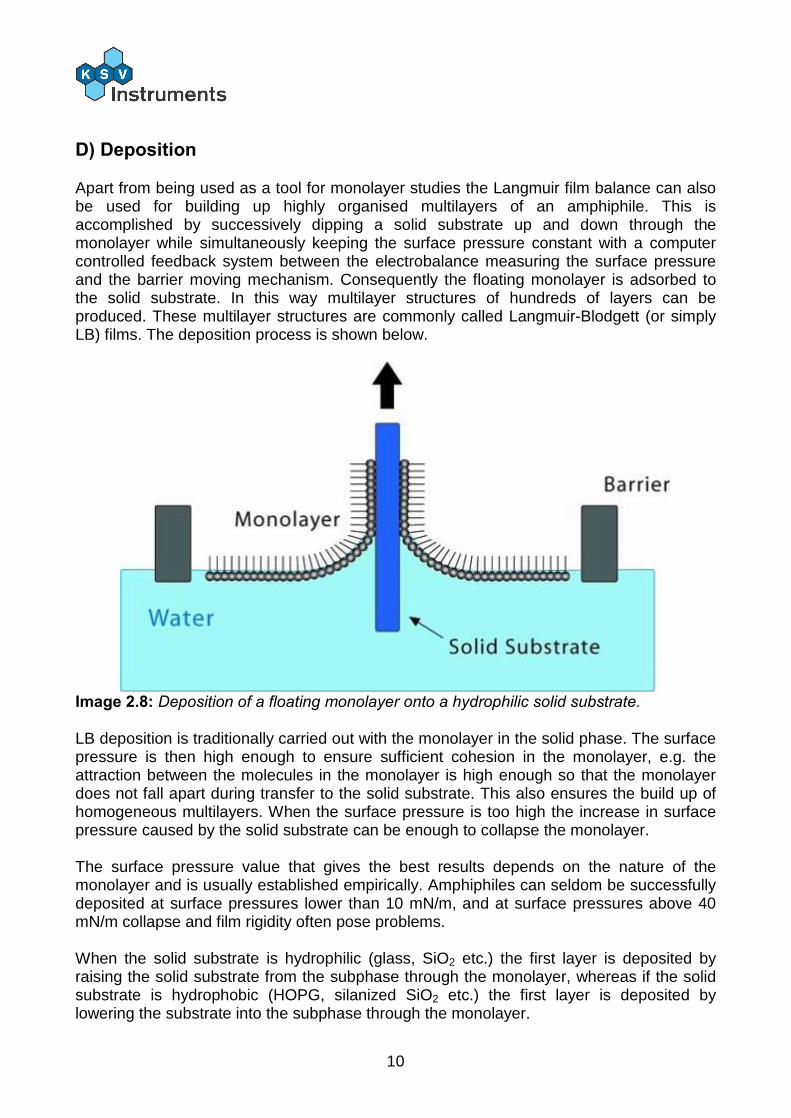
Apart from being used as a tool for monolayer studies the Langmuir film balance can also be used for building up highly organised multilayers of an amphiphile. This is accomplished by successively dipping a solid substrate up and down through the monolayer while simultaneously keeping the surface pressure constant with a computer controlled feedback system between the electrobalance measuring the surface pressure and the barrier moving mechanism. Consequently the floating monolayer is adsorbed to the solid substrate. In this way multilayer structures of hundreds of layers can be produced. These multilayer structures are commonly called Langmuir-Blodgett (or simply LB) films. The deposition process is shown below.
Image 2.8: Deposition of a floating monolayer onto a hydrophilic solid substrate. LB deposition is traditionally carried out with the monolayer in the solid phase. The surface pressure is then high enough to ensure sufficient cohesion in the monolayer, e.g. the attraction between the molecules in the monolayer is high enough so that the monolayer does not fall apart during transfer to the solid substrate. This also ensures the build up of homogeneous multilayers. When the surface pressure is too high the increase in surface pressure caused by the solid substrate can be enough to collapse the monolayer. The surface pressure value that gives the best results depends on the nature of the monolayer and is usually established empirically. Amphiphiles can seldom be successfully deposited at surface pressures lower than 10 mN/m, and at surface pressures above 40 mN/m collapse and film rigidity often pose problems. When the solid substrate is hydrophilic (glass, SiO2 etc.) the first layer is deposited by raising the solid substrate from the subphase through the monolayer, whereas if the solid substrate is hydrophobic (HOPG, silanized SiO2 etc.) the first layer is deposited by lowering the substrate into the subphase through the monolayer.
11
There are several parameters that affect on what type of LB film is produced. These are the nature of the spread film, the subphase composition and temperature, the surface pressure during the deposition and the deposition speed, the type and nature of the solid substrate and the time the solid substrate is stored in air or in the subphase between the deposition cycles.
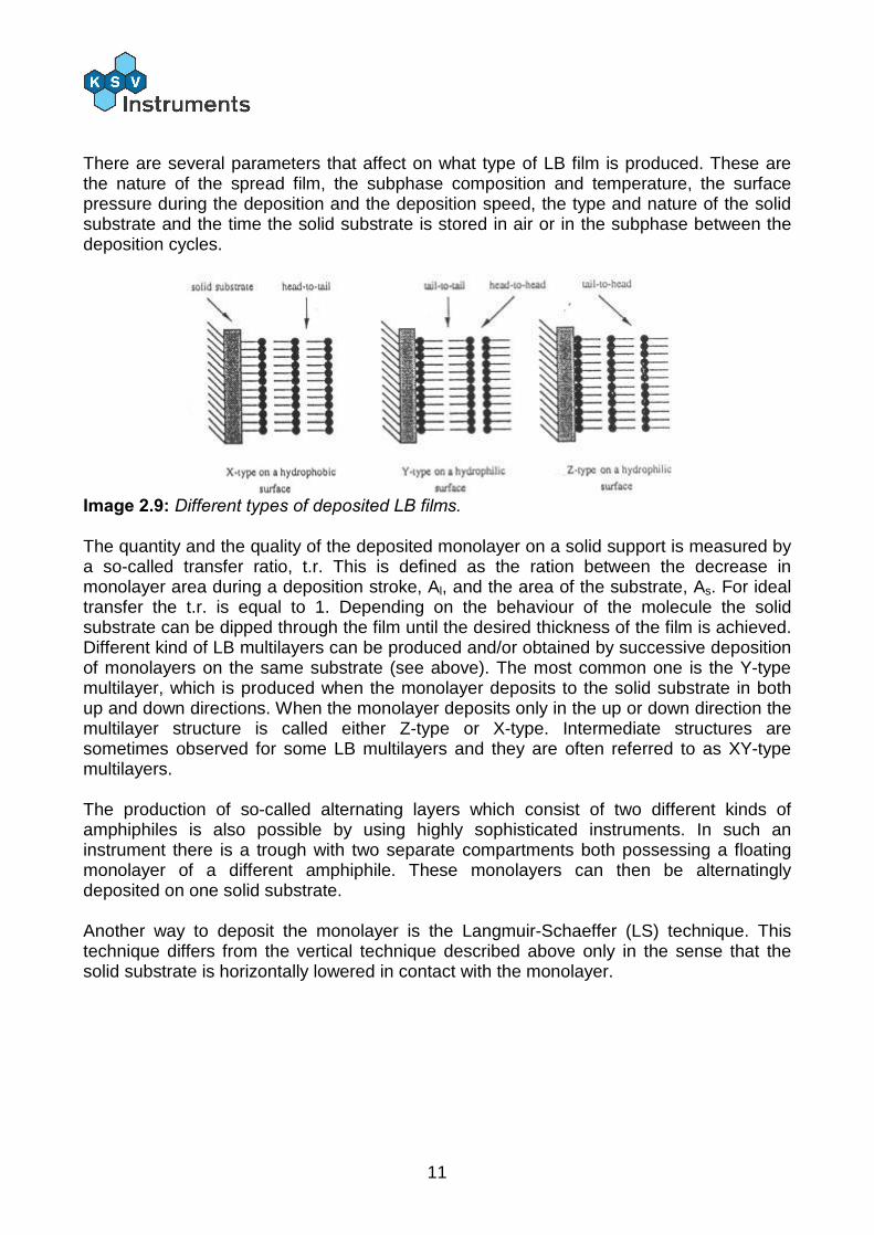
Image 2.9: Different types of deposited LB films. The quantity and the quality of the deposited monolayer on a solid support is measured by a so-called transfer ratio, t.r. This is defined as the ration between the decrease in monolayer area during a deposition stroke, Al, and the area of the substrate, As. For ideal transfer the t.r. is equal to 1. Depending on the behaviour of the molecule the solid substrate can be dipped through the film until the desired thickness of the film is achieved. Different kind of LB multilayers can be produced and/or obtained by successive deposition of monolayers on the same substrate (see above). The most common one is the Y-type multilayer, which is produced when the monolayer deposits to the solid substrate in both up and down directions. When the monolayer deposits only in the up or down direction the multilayer structure is called either Z-type or X-type. Intermediate structures are sometimes observed for some LB multilayers and they are often referred to as XY-type multilayers. The production of so-called alternating layers which consist of two different kinds of amphiphiles is also possible by using highly sophisticated instruments. In such an instrument there is a trough with two separate compartments both possessing a floating monolayer of a different amphiphile. These monolayers can then be alternatingly deposited on one solid substrate. Another way to deposit the monolayer is the Langmuir-Schaeffer (LS) technique. This technique differs from the vertical technique described above only in the sense that the solid substrate is horizontally lowered in contact with the monolayer.

12
2.4. Further Reading
Adamson, A. W., Physical Chemistry of Surfaces, Wiley&Sons (1976) Wu, S., Polymer Interface & Adhesion, Marcel Dekker, N.Y. (1982) Couper, A., Investigations of Surfaces and Interfaces - Part A, B. Rossiter, R. C. Baetzold eds, Phys. Meth. Chem Ser vol XI A (1993) Hansen, F. K. and Rodsrun, G., J. Coll & Inter Sci 141, 1-12(1991) Roberts, G., Ed. Langmuir-Blodgett Films, Plenum Press, New York (1990) Swalen, J.D.; Allara, D.L.; Andrade, J.D.; Chandross, E.A.; Garoff, S.; Israelachvili,
J.; McCarthy, T.J.; Murray, R.; Pease, R.F.; Rabolt, J.F.; Wynne, K.J.; Yu, H. Langmuir, 3 (1987) 932
Breton, M. J. Macromol. Sci. Rev. Macromol. Chem., C21 (1981) 61 Petty, M.C. Thin Solid Films, 210/211 (1992) 417 Pockels, A. Nature, 46 (1892) 418 Pockels, A. Nature, 43 (1891) 437 Langmuir, I. J. Am. Chem. Soc., 39 (1917) 1848 Blodgett, K.B. J. Am. Chem. Soc., 57 (1935) 1007 A.W.Adamson, Physical Chemistry of Surfaces, Wiley & Sons, New York (1976) Shaw, D.J., Introduction to Colloid and Surface Chemistry, Butterworth & Co,
London (1980) Laughlin, R.G. The Aqueous Phase Behaviour of Surfactants, Academic Press Inc.,
San Diego (1994) Chattoraj, D.K.; Birdi, K.S. Adsorption and the Gibbs Surface Excess, Plenum
Press, New York (1984) Gaines, G.L., Insoluble Monolayers at the Liquid-Gas Interface, Wiley-Interscience,
New York (1966) Binks, B.P. Adv. Colloid Interface Sci., 34 (1991) 343 Harkins, W.D., The Physical Chemistry of Surface Films, Reinhold, New York
(1952)

13
3. LayerBuilder The KSV LayerBuilder™ interface unit is an interface and nexus point between the computer and the various connected devices that comprise an LB measurement system. A running PC program is required for the proper operation of the LayerBuilder interface unit.
Image 3.1: The KSV LayerBuilder interface unit.
A) Display
The display shows relevant measurement data. Typically the top row shows surface pressure and the bottom row shows barrier position. The bottom row displays various status notifications, such as Limit when the barriers have reached their limit switch.
B) Keypad
When the LB software’s control panel (Manual Control Unit) is open, the keypad at the front of the LayerBuilder can be used to control positions of the barriers and dipper. On the left-hand side are two sets of controls for the barrier positions. The buttons, from left to right, are close barriers, stop and open barriers. With only one barrier drive connected (Systems 1 and 2, optional with System 3), the lower set can be used to control a stirrer if one is connected (the open or close buttons turn on the stirrer, the stop button turns the stirrer off). On the right-hand side are the controls for the dipper. The top-left button lifts the dipper, the bottom-left button lowers the dipper and the button on the right stops the dipper.
14
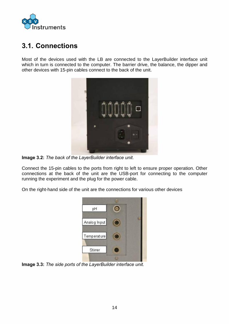
3.1. Connections
Most of the devices used with the LB are connected to the LayerBuilder interface unit which in turn is connected to the computer. The barrier drive, the balance, the dipper and other devices with 15-pin cables connect to the back of the unit.
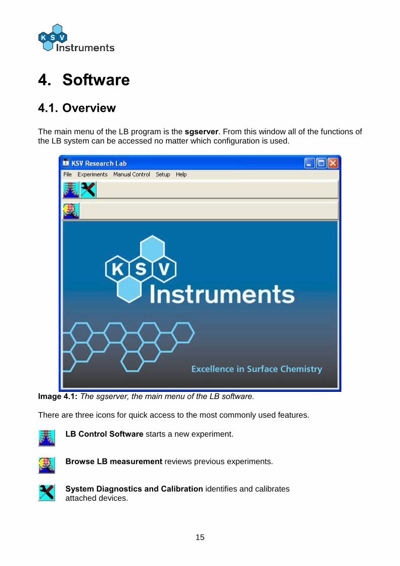
Image 3.2: The back of the LayerBuilder interface unit. Connect the 15-pin cables to the ports from right to left to ensure proper operation. Other connections at the back of the unit are the USB-port for connecting to the computer running the experiment and the plug for the power cable. On the right-hand side of the unit are the connections for various other devices
Image 3.3: The side ports of the LayerBuilder interface unit.
15
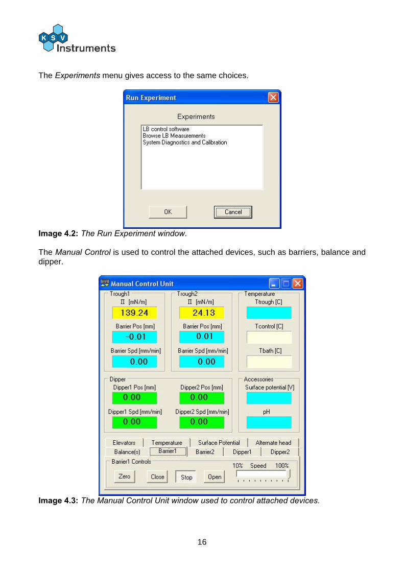
4. Software 4.1. Overview
The main menu of the LB program is the sgserver. From this window all of the functions of the LB system can be accessed no matter which configuration is used.
Image 4.1: The sgserver, the main menu of the LB software. There are three icons for quick access to the most commonly used features.
LB Control Software starts a new experiment.
Browse LB measurement reviews previous experiments.
System Diagnostics and Calibration identifies and calibrates attached devices.
16
The Experiments menu gives access to the same choices.
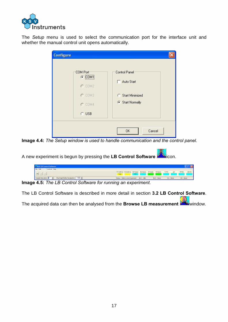
Image 4.2: The Run Experiment window. The Manual Control is used to control the attached devices, such as barriers, balance and dipper.
Image 4.3: The Manual Control Unit window used to control attached devices.
17
The Setup menu is used to select the communication port for the interface unit and whether the manual control unit opens automatically.
Image 4.4: The Setup window is used to handle communication and the control panel.
A new experiment is begun by pressing the LB Control Software icon.
Image 4.5: The LB Control Software for running an experiment. The LB Control Software is described in more detail in section 3.2 LB Control Software.
The acquired data can then be analysed from the Browse LB measurement window.
18
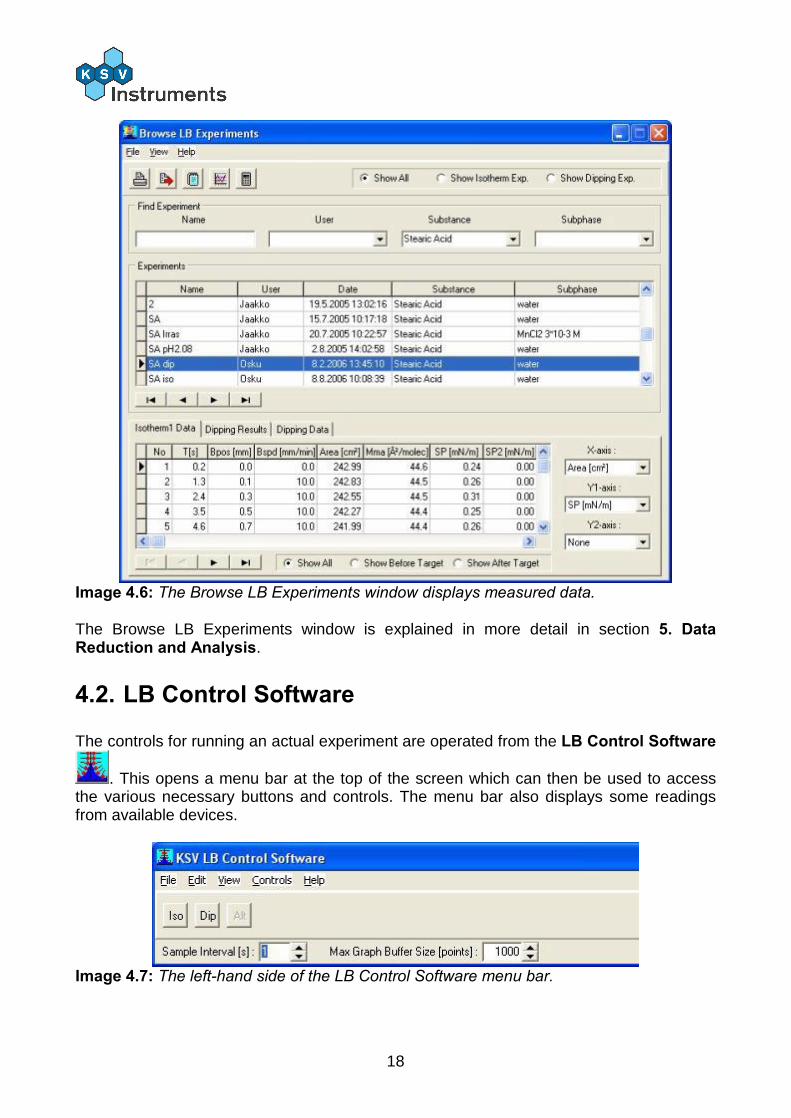
Image 4.6: The Browse LB Experiments window displays measured data. The Browse LB Experiments window is explained in more detail in section 5. Data Reduction and Analysis.
4.2. LB Control Software
The controls for running an actual experiment are operated from the LB Control Software
. This opens a menu bar at the top of the screen which can then be used to access the various necessary buttons and controls. The menu bar also displays some readings from available devices.
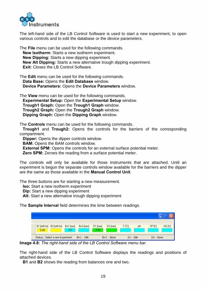
Image 4.7: The left-hand side of the LB Control Software menu bar.
19
The left-hand side of the LB Control Software is used to start a new experiment, to open various controls and to edit the database or the device parameters. The File menu can be used for the following commands.
New Isotherm: Starts a new isotherm experiment. New Dipping: Starts a new dipping experiment. New Alt Dipping: Starts a new alternative trough dipping experiment. Exit: Closes the LB Control Software.
The Edit menu can be used for the following commands.
Data Base: Opens the Edit Database window. Device Parameters: Opens the Device Parameters window.
The View menu can be used for the following commands.
Experimental Setup: Open the Experimental Setup window. Trough1 Graph: Open the Trough1 Graph window. Trough2 Graph: Open the Trough2 Graph window. Dipping Graph: Open the Dipping Graph window.
The Controls menu can be used for the following commands.
Trough1 and Trough2: Opens the controls for the barriers of the corresponding compartment.
Dipper: Opens the dipper controls window. BAM: Opens the BAM controls window. External SPM: Opens the controls for an external surface potential meter. Zero SPM: Zeroes the reading from a surface potential meter.
The controls will only be available for those instruments that are attached. Until an experiment is begun the separate controls window available for the barriers and the dipper are the same as those available in the Manual Control Unit. The three buttons are for starting a new measurement.
Iso: Start a new isotherm experiment Dip: Start a new dipping experiment Alt: Start a new alternative trough dipping experiment
The Sample Interval field determines the time between readings.
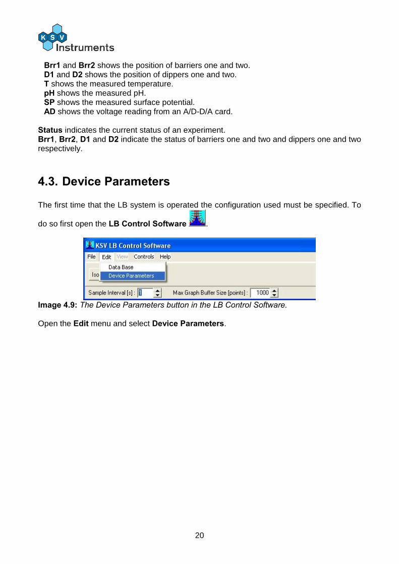
Image 4.8: The right-hand side of the LB Control Software menu bar. The right-hand side of the LB Control Software displays the readings and positions of attached devices.
B1 and B2 shows the reading from balances one and two.
20
Brr1 and Brr2 shows the position of barriers one and two. D1 and D2 shows the position of dippers one and two. T shows the measured temperature. pH shows the measured pH. SP shows the measured surface potential. AD shows the voltage reading from an A/D-D/A card.
Status indicates the current status of an experiment. Brr1, Brr2, D1 and D2 indicate the status of barriers one and two and dippers one and two respectively.
4.3. Device Parameters
The first time that the LB system is operated the configuration used must be specified. To
do so first open the LB Control Software .
Image 4.9: The Device Parameters button in the LB Control Software. Open the Edit menu and select Device Parameters.
21
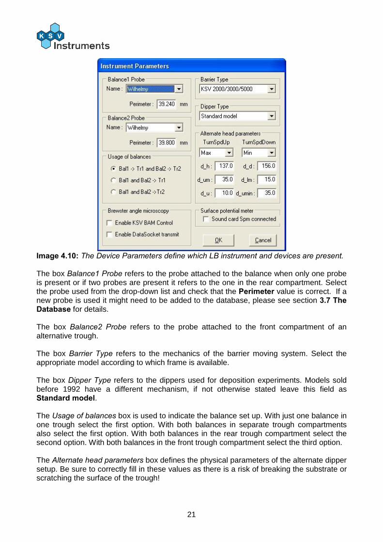
Image 4.10: The Device Parameters define which LB instrument and devices are present. The box Balance1 Probe refers to the probe attached to the balance when only one probe is present or if two probes are present it refers to the one in the rear compartment. Select the probe used from the drop-down list and check that the Perimeter value is correct. If a new probe is used it might need to be added to the database, please see section 3.7 The Database for details. The box Balance2 Probe refers to the probe attached to the front compartment of an alternative trough. The box Barrier Type refers to the mechanics of the barrier moving system. Select the appropriate model according to which frame is available. The box Dipper Type refers to the dippers used for deposition experiments. Models sold before 1992 have a different mechanism, if not otherwise stated leave this field as Standard model. The Usage of balances box is used to indicate the balance set up. With just one balance in one trough select the first option. With both balances in separate trough compartments also select the first option. With both balances in the rear trough compartment select the second option. With both balances in the front trough compartment select the third option. The Alternate head parameters box defines the physical parameters of the alternate dipper setup. Be sure to correctly fill in these values as there is a risk of breaking the substrate or scratching the surface of the trough!
22
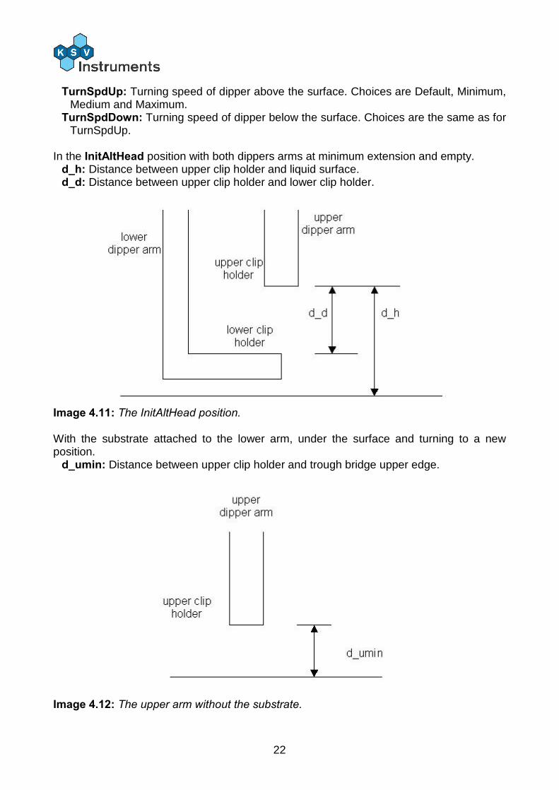
TurnSpdUp: Turning speed of dipper above the surface. Choices are Default, Minimum, Medium and Maximum.
TurnSpdDown: Turning speed of dipper below the surface. Choices are the same as for TurnSpdUp.
In the InitAltHead position with both dippers arms at minimum extension and empty.
d_h: Distance between upper clip holder and liquid surface. d_d: Distance between upper clip holder and lower clip holder.
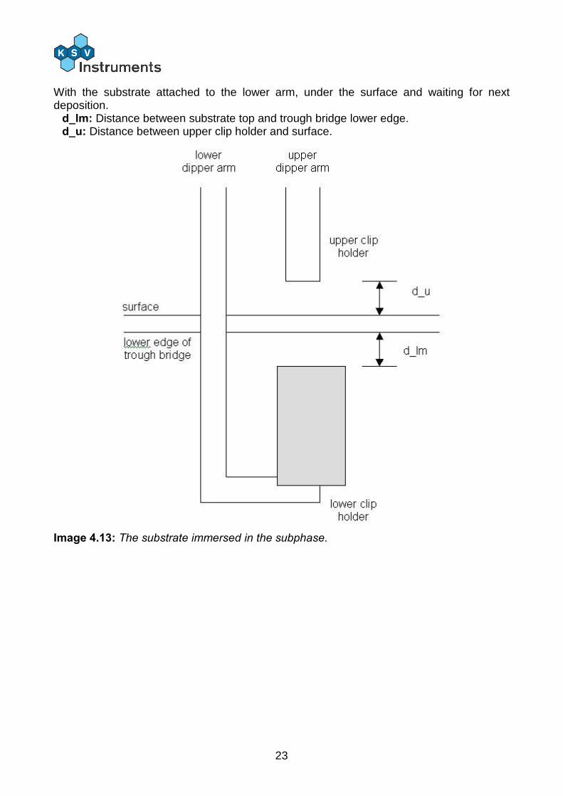
Image 4.11: The InitAltHead position. With the substrate attached to the lower arm, under the surface and turning to a new position.
d_umin: Distance between upper clip holder and trough bridge upper edge.
Image 4.12: The upper arm without the substrate.
23
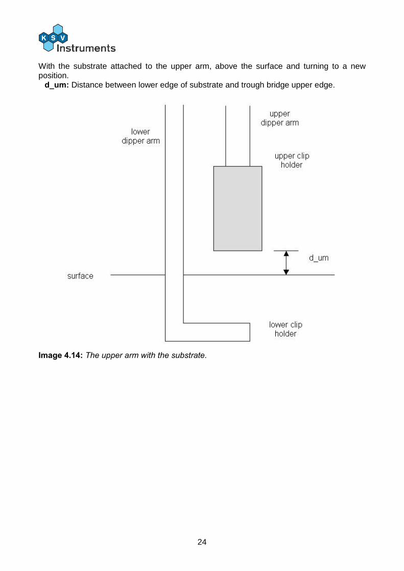
With the substrate attached to the lower arm, under the surface and waiting for next deposition.
d_lm: Distance between substrate top and trough bridge lower edge. d_u: Distance between upper clip holder and surface.
Image 4.13: The substrate immersed in the subphase.
24
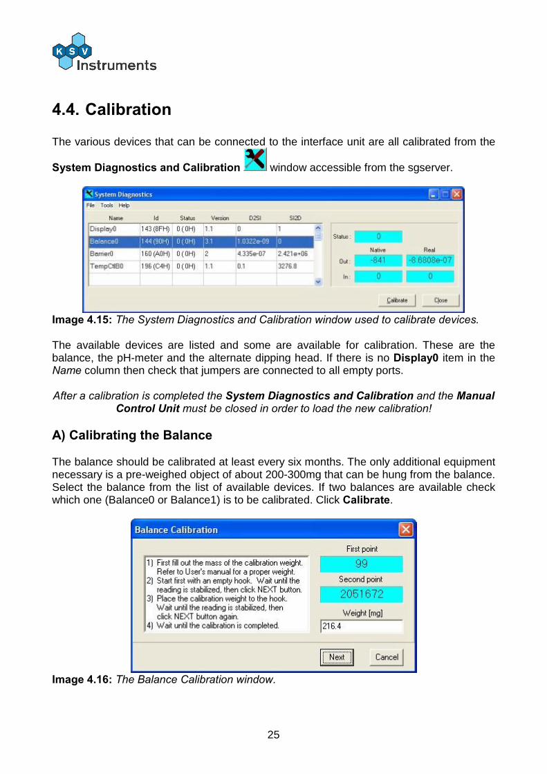
With the substrate attached to the upper arm, above the surface and turning to a new position.
d_um: Distance between lower edge of substrate and trough bridge upper edge.
Image 4.14: The upper arm with the substrate.
25
4.4. Calibration
The various devices that can be connected to the interface unit are all calibrated from the
System Diagnostics and Calibration window accessible from the sgserver.
Image 4.15: The System Diagnostics and Calibration window used to calibrate devices. The available devices are listed and some are available for calibration. These are the balance, the pH-meter and the alternate dipping head. If there is no Display0 item in the Name column then check that jumpers are connected to all empty ports. After a calibration is completed the System Diagnostics and Calibration and the Manual
Control Unit must be closed in order to load the new calibration!
A) Calibrating the Balance
The balance should be calibrated at least every six months. The only additional equipment necessary is a pre-weighed object of about 200-300mg that can be hung from the balance. Select the balance from the list of available devices. If two balances are available check which one (Balance0 or Balance1) is to be calibrated. Click Calibrate.
Image 4.16: The Balance Calibration window.
26
Hang a Wilhelmy plate from the balance to help stabilise the first reading. Insert the weight of the pre-weighed calibration object in the Weight field in mg. Wait for the reading in the First point field to stabilise (third digit from the right does not change significantly). Press Next. The First point value will lock and the Second point value will start to change. Place the calibration object on the balance and again wait for the values to stabilise. Press Next to complete the calibration.
Check that the weight is in mg!
B) Calibrating the pH-Meter
The calibration of the pH-meter requires three standard buffer solutions of known pH values, for example with pH of 4, 7 and 10. Select the pH-meter from the list of available devices and press Calibrate. Follow the instructions on-screen.
C) Calibrating the Alternate Dipping Head
The alternate dipping head should not ever need to be calibrated but the option is present. Select the alternate dipping head from the devices list (Altern0) and click Calibrate. Then follow the instructions on-screen.
27
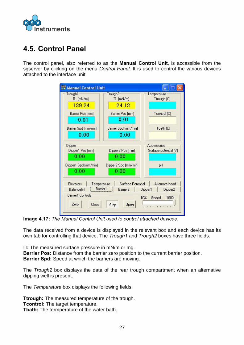
4.5. Control Panel
The control panel, also referred to as the Manual Control Unit, is accessible from the sgserver by clicking on the menu Control Panel. It is used to control the various devices attached to the interface unit.
Image 4.17: The Manual Control Unit used to control attached devices. The data received from a device is displayed in the relevant box and each device has its own tab for controlling that device. The Trough1 and Trough2 boxes have three fields. : The measured surface pressure in mN/m or mg. Barrier Pos: Distance from the barrier zero position to the current barrier position. Barrier Spd: Speed at which the barriers are moving. The Trough2 box displays the data of the rear trough compartment when an alternative dipping well is present. The Temperature box displays the following fields. Ttrough: The measured temperature of the trough. Tcontrol: The target temperature. Tbath: The termperature of the water bath.
28
The Dipper box displays the status of any attached dippers. Dipper1 Pos and Dipper2 Pos: Distance from the dipper zero position to the current dipper position. Dipper1 Spd and Dipper2 Spd: Speed at which the dipper is moving The Accessories box displays readings from two devices. Surface potential: The surface potential measured by the surface potential probe. pH: The pH reading obtained with the pH-meter. The tabs along the bottom of the Manual Control Unit window control the various devices. Please note that tabs will be available for the available devices. The Balance tab controls any attached balances. The current reading can be zeroed with the Zero Balance1 and the Zero Balance2 buttons, the balance2 referring to a second balance usually in the front compartment of an alternate trough. The Show as mN/m or mg choice adjusts the units of the reading shown in the field. The balance itself measures mg but the reading is adjusted to mN/m for data analysis purposes. From the Barrier1 tab the barriers can be moved. Zero: Zeroes the current position of the barriers, usually only done in the fully open position. Close: Starts to move the barriers closer together. Stop: Stops the barriers' movement. Open: Starts to move the barriers further apart. The Speed slider can be used to select the speed of the movement. 100% represents the maximum possible speed and as the slider is moved to the left the speed decreases. The Barrier2 tab looks identical to the Barrier1 tab and is available when an alternate trough is attached. It is used to control the barriers of the front compartment. The Dipper1 tab is very similar to the barrier tabs and is used to move the dipper head. Zero: Zeroes the current position of the dipper, usually done with the substrate touching the surface. Up: Starts to move the dipper upwards. Stop: Stops the dipper's movement. Down: Starts to move the dipper downwards. The Dipper2 tab looks identical to the Dipper2 tab and is available when an alternate trough is attached. It is used to control the lower dipper.
29
The Elevators tab is available with KSV 5000 systems. It controls up to four possible elevators that hold devices such as the balance or the dipper. Note that in order to move an elevator the button must be kept pressed! Up#: Moves the specified elevator upwards. Down#: Moves the specified elevator downwards. The Temperature tab controls are used for the following. Stop: Stops all software control of the water bath. Bath: Sets the temperature of the water bath. Control: The temperature of the water bath is adjusted according to readings from the temperature probe. Off: Turns the RS-232 communication off. On: Turns the RS-232 communication on. Min: Minimum allowed temperature. Set value: Target temperature. Max: Maximum allowed temperature.
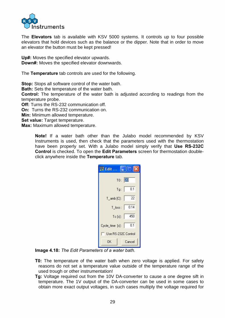
Note! If a water bath other than the Julabo model recommended by KSV Instruments is used, then check that the parameters used with the thermostation have been properly set. With a Julabo model simply verify that Use RS-232C Control is checked. To open the Edit Parameters screen for thermostation double-click anywhere inside the Temperature tab.
Image 4.18: The Edit Parameters of a water bath. T0: The temperature of the water bath when zero voltage is applied. For safety
reasons do not set a temperature value outside of the temperature range of the used trough or other instrumentation!
Tg: Voltage required out from the 10V DA-converter to cause a one degree sift in temperature. The 1V output of the DA-converter can be used in some cases to obtain more exact output voltages, in such cases multiply the voltage required for
30
the 1V DA-converter by ten to obtain the voltage required for the 10V DA-converter. Write this value in the Tg field. With a water circulator sensitivity of 10mV/K and using 1V output Tg = 10 * 0.01 = 0.1.
T_amb: The ambient, i.e. room, temperature. T_loss: A representative value of the amount of heat lost from the system, obtained
by setting the temperature of the bath to a set value and then with the system stabilised measuring the temperature of the subphase. Fit the values to the following equation to obtain the T_loss value.
Tc: Time constant for the thermostation of the sample vessel. Cycle_time: The interval with which the software communicates with the water
bath. Use RS-232C Control: Check this box to indicate that the water bath is controlled
by RS-232C.
The Surface Potential tab is for the surface potential meter. Zero Surface Potential: Zeroes the reading in the Surface Potential field. The Alternate Head tab is for controlling the movement of dippers in an alternate trough. Trough1: Turns the dippers to the rear compartment. Center: Turns the dippers to the center compartment. Trough2: Turns the dippers to the front compartment. The Upper Clip controls move Dipper1, the Lower Clip controls move Dipper2. Open: Opens the dipper. Close: Closes the dipper.
31
5. Preliminaries 5.1. Experimental Setup
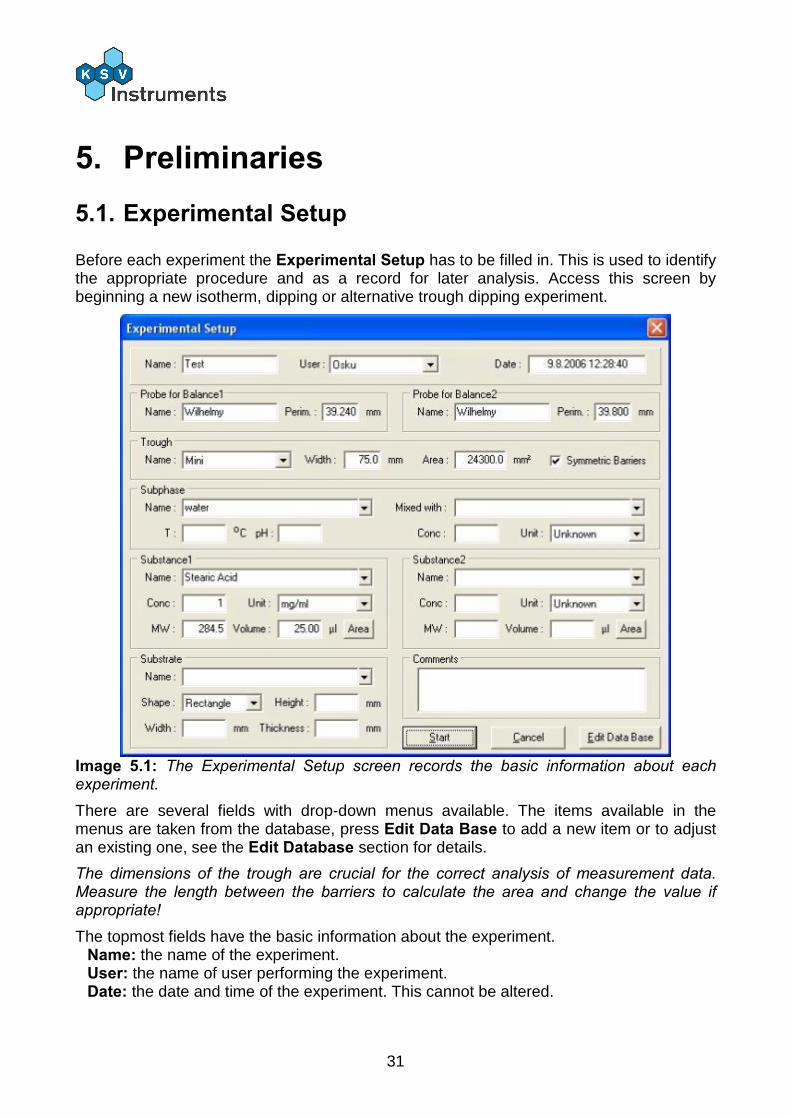
Before each experiment the Experimental Setup has to be filled in. This is used to identify the appropriate procedure and as a record for later analysis. Access this screen by beginning a new isotherm, dipping or alternative trough dipping experiment.
Image 5.1: The Experimental Setup screen records the basic information about each experiment.
There are several fields with drop-down menus available. The items available in the menus are taken from the database, press Edit Data Base to add a new item or to adjust an existing one, see the Edit Database section for details.
The dimensions of the trough are crucial for the correct analysis of measurement data. Measure the length between the barriers to calculate the area and change the value if appropriate!
The topmost fields have the basic information about the experiment. Name: the name of the experiment. User: the name of user performing the experiment. Date: the date and time of the experiment. This cannot be altered.
32
The Probe for balance box has information on the probe hanging from the balance. With two balances check which balance functions as Balance2 and that the correct probes are selected.
The Trough box identifies the attached trough. Select the appropriate trough from the drop-down list or type in the name of a new one. Check that the Width and Area fields are filled, these are essential for analysis. If the barriers will not be compressed symmetrically then a new trough must be inserted into the database for which the Symmetric Barriers box is unchecked.
The Subphase box identifies the liquid that forms the subphase, most often water. If a salt is dissolved into the liquid then indicate so in the Mixed with field. Temperature, pH and the concentration of the salt can be indicated in the appropriate fields.
The Substance1 and Substance2 boxes indicate the surfactant placed on top of the subphase, substance two referring to the surfactant in the front compartment.
Name: the name of the surfactant Conc: the concentration of surfactant in the organic solvent. Unit: the units in which the concentration is indicated. MW: the molecular weight of the surfactant. Volume: the volume of organic solvent placed.
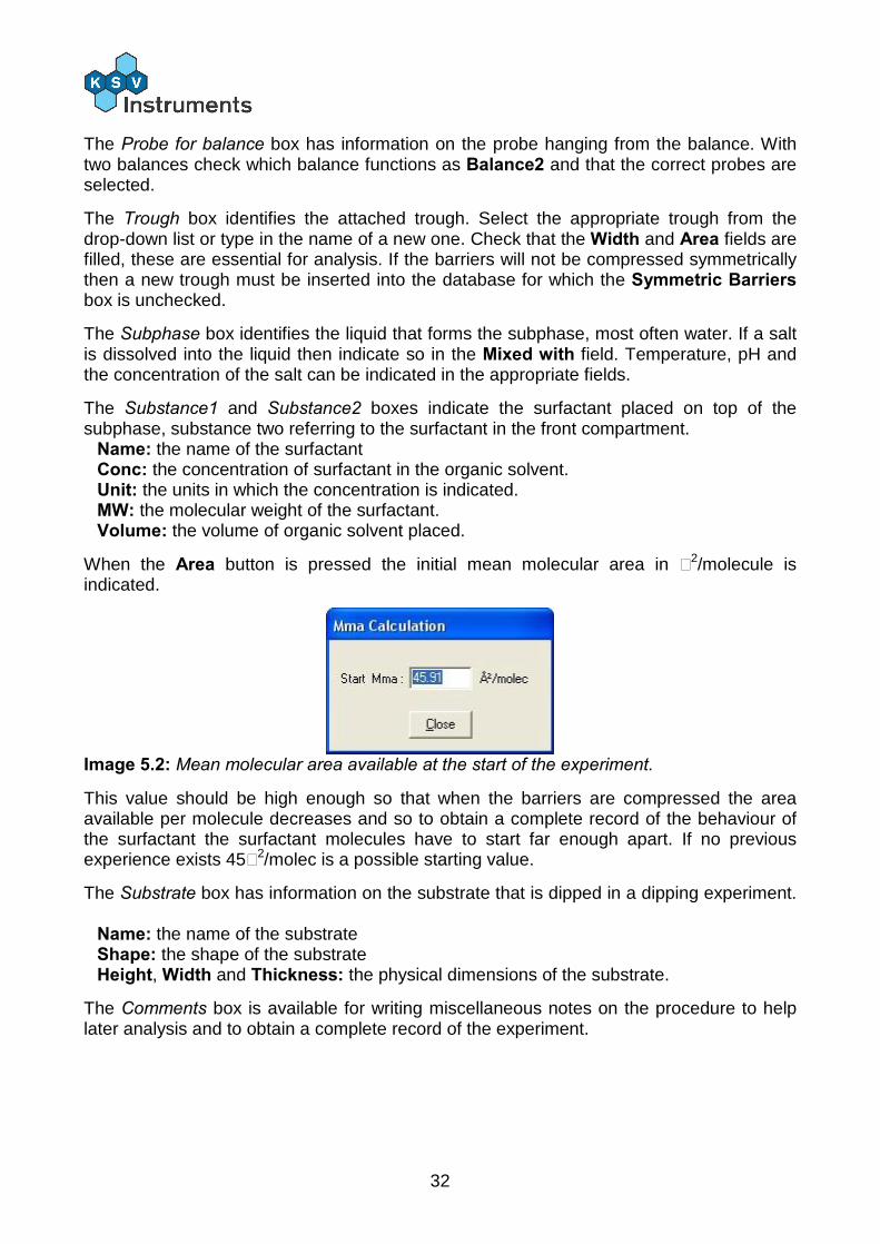
When the Area button is pressed the initial mean molecular area in Å2/molecule is indicated.
Image 5.2: Mean molecular area available at the start of the experiment.
This value should be high enough so that when the barriers are compressed the area available per molecule decreases and so to obtain a complete record of the behaviour of the surfactant the surfactant molecules have to start far enough apart. If no previous experience exists 45Å2/molec is a possible starting value.
The Substrate box has information on the substrate that is dipped in a dipping experiment.
Name: the name of the substrate Shape: the shape of the substrate Height, Width and Thickness: the physical dimensions of the substrate.
The Comments box is available for writing miscellaneous notes on the procedure to help later analysis and to obtain a complete record of the experiment.
33
5.2. The Database
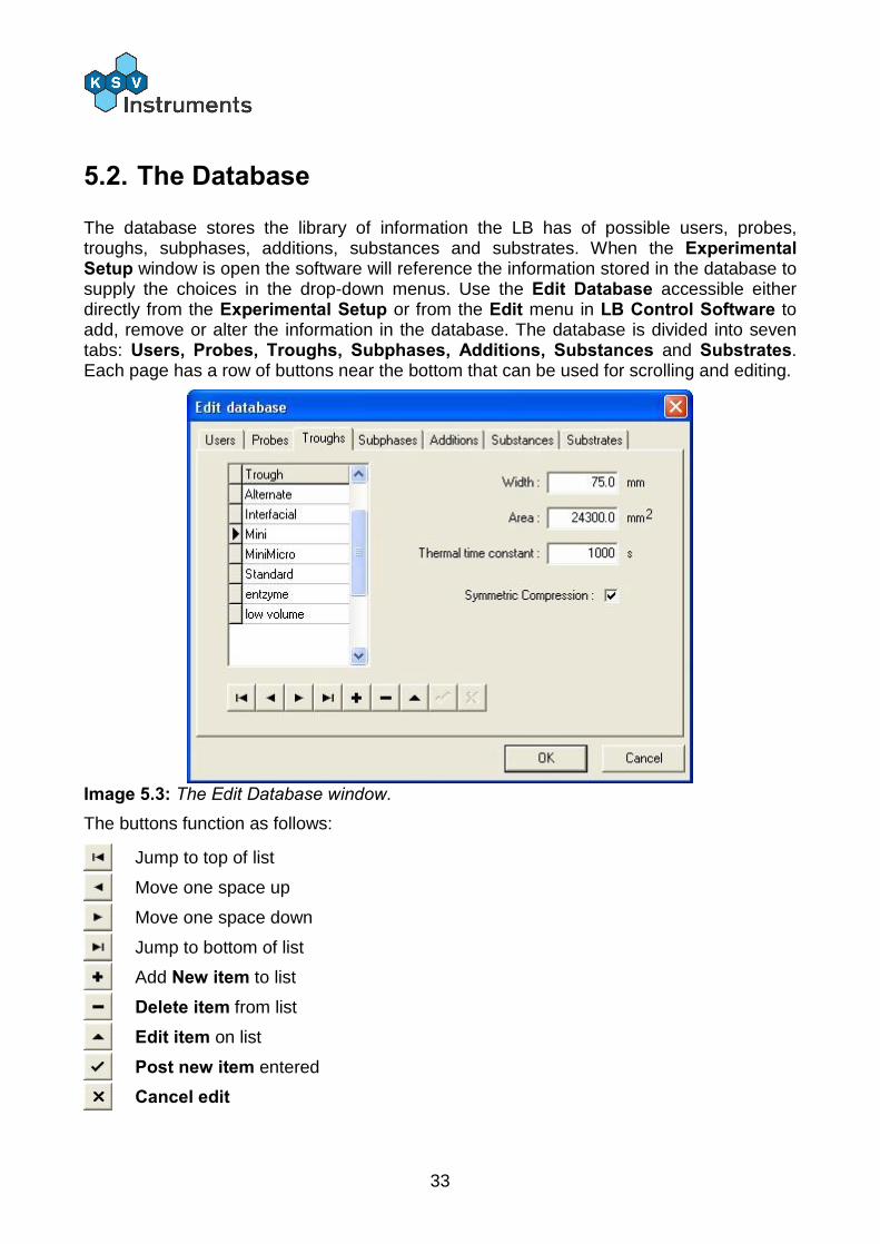
The database stores the library of information the LB has of possible users, probes, troughs, subphases, additions, substances and substrates. When the Experimental Setup window is open the software will reference the information stored in the database to supply the choices in the drop-down menus. Use the Edit Database accessible either directly from the Experimental Setup or from the Edit menu in LB Control Software to add, remove or alter the information in the database. The database is divided into seven tabs: Users, Probes, Troughs, Subphases, Additions, Substances and Substrates. Each page has a row of buttons near the bottom that can be used for scrolling and editing.
Image 5.3: The Edit Database window.
The buttons function as follows:
Jump to top of list
Move one space up
Move one space down
Jump to bottom of list
Add New item to list
Delete item from list
Edit item on list
Post new item entered
Cancel edit
34
A) Users In the Users tab a list of current users will appear. To add a new user press the New item button, enter the new name in the field space and press Post new item. Press OK to continue.
B) Probes The available names of the probes are edited like those of users. The perimeter of a probe must be filled in mm to obtain correct readings.
C) Troughs The available names of the troughs are edited like those of users. The additional fields give more information about each trough, and must be filled in to obtain correct readings. For a non-symmetric compression experiment create a new trough item with the appropriate measurements and unchecked Symmetric Compression box. The simplest non-symmetric compression can be achieved by removing one barrier.
D) Subphases The available names of the subphases are edited like those of users. The additional fields give more information about each substance.
Density: Density of liquid. : Surface tension of liquid.
Viscosity: Viscosity of the liquid. MW: Molecular weight of liquid.
E) Additions The available names of the additions are edited like those of users. The additional fields give more information about each substance.
Density: Density of liquid. MW: Molecular weight of liquid.
F) Substances The available names of the substances are edited like those of users. The additional fields give more information about each substance. Density: Density of liquid. MW: Molecular weight of liquid.
G) Substrates The available names of the substances are edited like those of users. The additional fields give more information about each substance. Density: Density of solid. Sfe: Surface free energy of solid. MW: Molecular weight of solid.
35
5.3. Cleaning
Use rubber gloves to minimise oils from the skin contaminating the apparatus. The importance of cleanliness cannot be overstated! The troughs used by KSV can be removed from the frame and carried to a sink for ease of cleaning. Take care not to scratch the surface. Clean the trough and barriers as appropriate, please check the device-specific manual for details. With the barriers fully open, fill the trough with distilled water and zero the reading of the balance. Begin closing the barriers and sucking on the surface of the water with an aspirator to remove decontaminants. When the barriers are fully closed check the balance reading to make sure that it has not changed unacceptably much (a large change indicates surfactants are present, as the water itself would not change surface pressure when compressed.). Once the cleaning is complete, check the level of the water. The target is that the water is at the same level as the edges of the trough. If the level is too low the surfactant might be able to slip by under the barrier and if the level is too high the surfactant might spill over.
5.4. Placing the surfactant
Mix the surfactant sample with a volatile organic solvent, for example chloroform and hexane. The organic solvent should be non-polar so that it will not mix with the water and volatile so that it will evaporate from the surface. A concentration of 1 mg/ml is usually a good choice to start investigations. Placing the solvent on the water should be done with care, gently push on the syringe to get a drop out of the needle and then touch the surface with the tip of the needle. Do not let the drop fall from the needle as some of the sample might be lost to the subphase as micelles and the surfactant does not spread evenly! Furthermore the waves caused by drops can carry surfactants to the edges of the trough. Wait 10-15min for the solvent to evaporate. Use this time to fill in the Experimental Setup for this experiment. Press on the appropriate icon to start a new experiment, this will first open the Experimental Setup. Double-check that the dimensions of the trough are correct as this plays an important part in the analysis of the obtained data.
36
6. Experiments 6.1. Overview
There are three experiment types available with the LB software. Every LB device can run an isotherm experiment, where the surface pressure is measured generally in relation to the area available per molecule (i.e. the motion of the barriers). When a trough with a well and a dipper is present, a dipping experiment can be run. This involves setting the surfactant to a desired density by measuring the surface pressure and then dipping a substrate through the monolayer in order to coat it. The third experiment type is the alternate dipping experiment. This requires a trough with a half-circle well and a two-armed dipper. The trough is split into three compartments connected by the subphase so that the lower arm of the dipper can move the substrate from one compartment to another below the surface. The center compartment is pure water. The two outer compartments can have any surfactant and are controlled by separate barrier drives and balances. All of the experiment types require the same preliminaries, check the previous section of the manual for details. The Trough Control window controls the movement of the barrier. In an isotherm experiment this could be to compress to a set surface pressure and begin to oscillate at a set frequency and amplitude. In a dipping or alternate dipping experiment this is typically to go to a set surface pressure and to hold that pressure (as the surfactant coats the substrate, the barriers must compress to retain the required surface pressure). At the set goal the Dipper Control window opens to control the dipper or the alternate dipper according to what is connected to the LB device. For step-by-step instructions on making measurements please see the appendix at the end of this manual.
37
6.2. Trough Controls
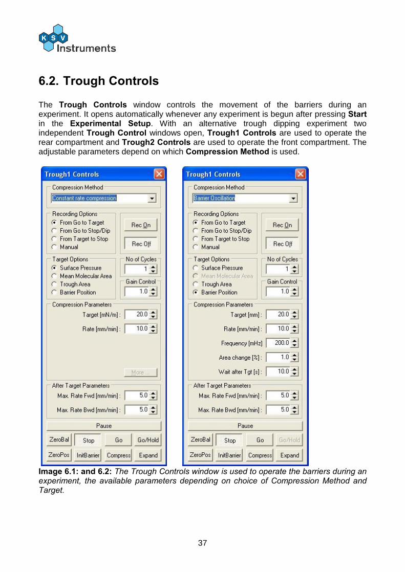
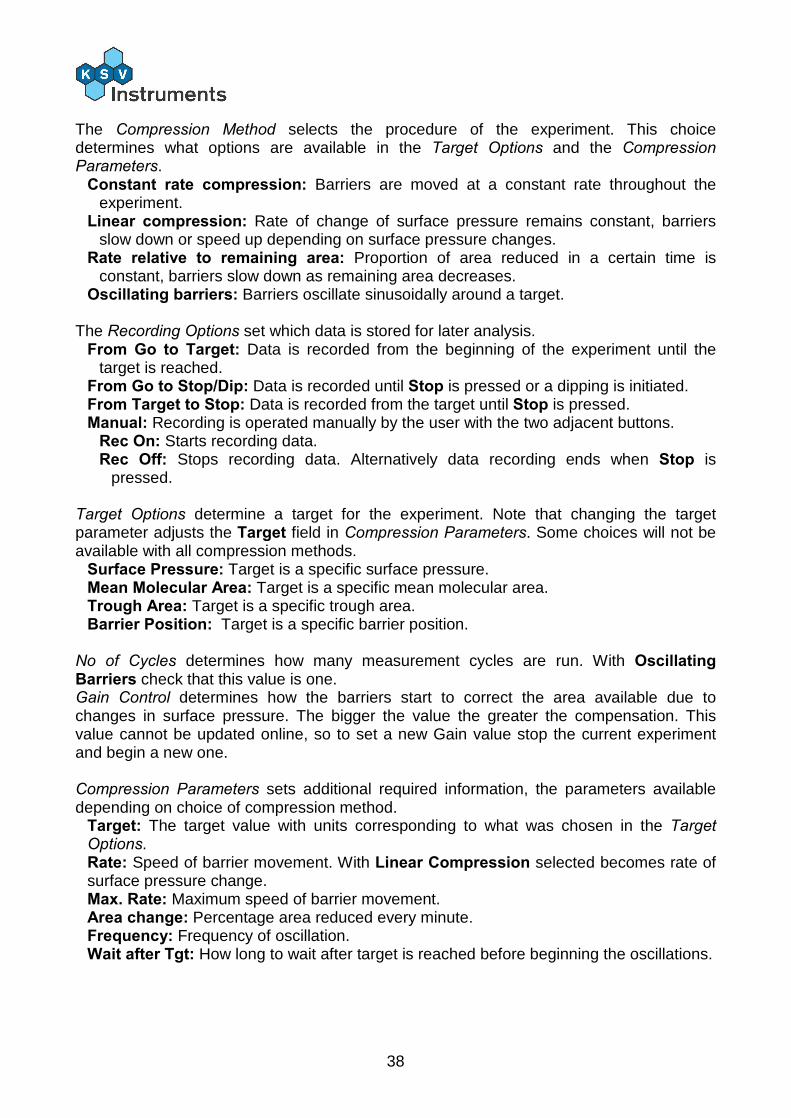
The Trough Controls window controls the movement of the barriers during an experiment. It opens automatically whenever any experiment is begun after pressing Start in the Experimental Setup. With an alternative trough dipping experiment two independent Trough Control windows open, Trough1 Controls are used to operate the rear compartment and Trough2 Controls are used to operate the front compartment. The adjustable parameters depend on which Compression Method is used.
Image 6.1: and 6.2: The Trough Controls window is used to operate the barriers during an experiment, the available parameters depending on choice of Compression Method and Target.
38
The Compression Method selects the procedure of the experiment. This choice determines what options are available in the Target Options and the Compression Parameters.
Constant rate compression: Barriers are moved at a constant rate throughout the experiment.
Linear compression: Rate of change of surface pressure remains constant, barriers slow down or speed up depending on surface pressure changes.
Rate relative to remaining area: Proportion of area reduced in a certain time is constant, barriers slow down as remaining area decreases.
Oscillating barriers: Barriers oscillate sinusoidally around a target. The Recording Options set which data is stored for later analysis.
From Go to Target: Data is recorded from the beginning of the experiment until the target is reached.
From Go to Stop/Dip: Data is recorded until Stop is pressed or a dipping is initiated. From Target to Stop: Data is recorded from the target until Stop is pressed. Manual: Recording is operated manually by the user with the two adjacent buttons.
Rec On: Starts recording data. Rec Off: Stops recording data. Alternatively data recording ends when Stop is
pressed. Target Options determine a target for the experiment. Note that changing the target parameter adjusts the Target field in Compression Parameters. Some choices will not be available with all compression methods.
Surface Pressure: Target is a specific surface pressure. Mean Molecular Area: Target is a specific mean molecular area. Trough Area: Target is a specific trough area. Barrier Position: Target is a specific barrier position.
No of Cycles determines how many measurement cycles are run. With Oscillating Barriers check that this value is one. Gain Control determines how the barriers start to correct the area available due to changes in surface pressure. The bigger the value the greater the compensation. This value cannot be updated online, so to set a new Gain value stop the current experiment and begin a new one. Compression Parameters sets additional required information, the parameters available depending on choice of compression method.
Target: The target value with units corresponding to what was chosen in the Target Options. Rate: Speed of barrier movement. With Linear Compression selected becomes rate of surface pressure change. Max. Rate: Maximum speed of barrier movement. Area change: Percentage area reduced every minute. Frequency: Frequency of oscillation. Wait after Tgt: How long to wait after target is reached before beginning the oscillations.
39
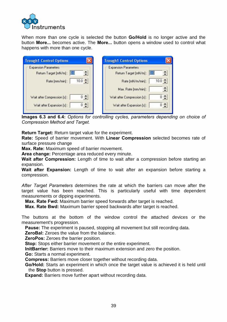
When more than one cycle is selected the button Go/Hold is no longer active and the button More... becomes active. The More... button opens a window used to control what happens with more than one cycle.
Images 6.3 and 6.4: Options for controlling cycles, parameters depending on choice of Compression Method and Target. Return Target: Return target value for the experiment. Rate: Speed of barrier movement. With Linear Compression selected becomes rate of surface pressure change Max. Rate: Maximum speed of barrier movement. Area change: Percentage area reduced every minute. Wait after Compression: Length of time to wait after a compression before starting an expansion. Wait after Expansion: Length of time to wait after an expansion before starting a compression. After Target Parameters determines the rate at which the barriers can move after the target value has been reached. This is particularly useful with time dependent measurements or dipping experiments.
Max. Rate Fwd: Maximum barrier speed forwards after target is reached. Max. Rate Bwd: Maximum barrier speed backwards after target is reached.
The buttons at the bottom of the window control the attached devices or the measurement's progression.
Pause: The experiment is paused, stopping all movement but still recording data. ZeroBal: Zeroes the value from the balance. ZeroPos: Zeroes the barrier position. Stop: Stops either barrier movement or the entire experiment. InitBarrier: Barriers move to their maximum extension and zero the position. Go: Starts a normal experiment. Compress: Barriers move closer together without recording data. Go/Hold: Starts an experiment in which once the target value is achieved it is held until
the Stop button is pressed. Expand: Barriers move further apart without recording data.
40
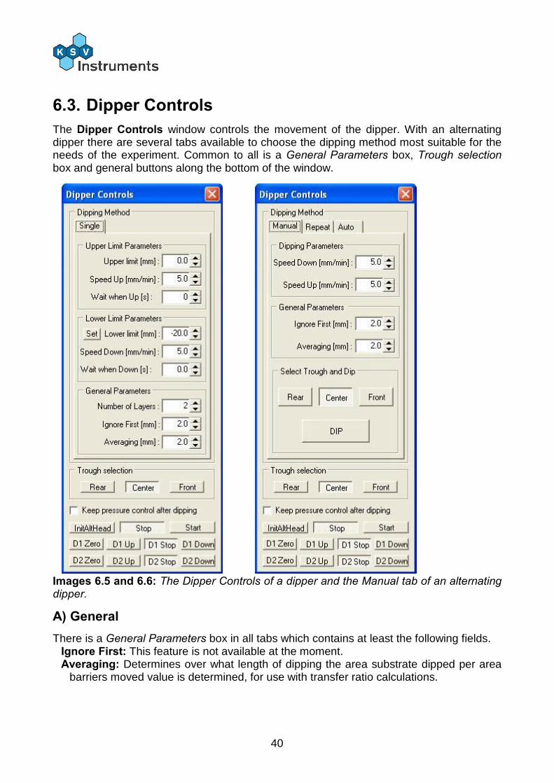
6.3. Dipper Controls The Dipper Controls window controls the movement of the dipper. With an alternating dipper there are several tabs available to choose the dipping method most suitable for the needs of the experiment. Common to all is a General Parameters box, Trough selection box and general buttons along the bottom of the window.
Images 6.5 and 6.6: The Dipper Controls of a dipper and the Manual tab of an alternating dipper.
A) General There is a General Parameters box in all tabs which contains at least the following fields.
Ignore First: This feature is not available at the moment. Averaging: Determines over what length of dipping the area substrate dipped per area
barriers moved value is determined, for use with transfer ratio calculations.
41
The controls available in all tabs are the buttons located at the bottom of the window. These begin with the Trough selection box that controls an alternate dipping head if one is attached.
Rear: Dippers move to rear compartment. Center: Dippers move to center compartment. Front: Dippers move to front compartment.
When the check box Keep pressure control after dipping is checked pressure is kept constant after all of the layers have been deposited. The buttons below control the dipper(s). Some buttons will not be available if the alternate dipper is not attached.
InitAltHead: The dippers are brought to their upmost position, turned to the center and the position is zeroed. Stop: Ends the dipping procedure. Start: Begins the dipping procedure. D# Zero: Zeroes the dipper position. D# Up: Moves the dipper up. D# Stop: Stops the dipper movement. D# Down: Moves the dipper down.
D1 and D2 refer to the upper and lower dipper respectively. With just one dipper it can be controlled with the D1 buttons.
B) Dipping Method Single This method is the only method available when a single-arm dipper is present.
The Upper Limit Parameters box adjusts the upwards movement of the dipping experiment.
Upper Limit: Height to which substrate is pulled up. Speed Up: Speed of upwards movement. Wait when Up: Length of time to wait above the surface before the next dip.
The Lower Limit Parameters box adjusts the downwards movement of the dipping experiment
Lower Limit: Depth to which substrate is lowered to. Speed Down: Speed of downwards movement. Wait when Down: Length of time to wait below the surface before the next raise.
The General Parameters box has general information on the experiment. Number of Layers: Number of layers to be deposited, remember that one layer is
deposited each time the substrate moves from the up to the down position or from the down to the up position.
C) Dipping Method Manual The Manual method is the simplest available for an alternating dipper. The user selects where and when to dip or lift the substrate step by step.
The Dipping Parameters box adjusts the movement parameters of the dipping experiment. Speed Down: Speed of downwards movement. Speed Up: Speed of upwards movement
42
The Select Trough and Dip box moves the dippers. Rear, Center and Front: Changes the dipper position to the respective compartment. DIP: Performs one dipping stroke upwards or downwards.
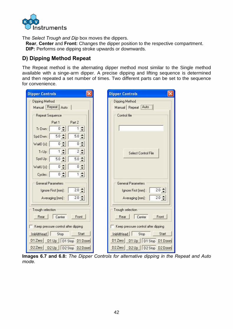
D) Dipping Method Repeat The Repeat method is the alternating dipper method most similar to the Single method available with a singe-arm dipper. A precise dipping and lifting sequence is determined and then repeated a set number of times. Two different parts can be set to the sequence for convenience.
Images 6.7 and 6.8: The Dipper Controls for alternative dipping in the Repeat and Auto mode.
43
The Repeat Sequence box has the possibility to divide the experiment into two parts, useful mainly to obtain the appropriate first layer on the substrate. Part 2 will be executed directly after Part 1 is finished.
Tr Dwn: Trough down, which compartment the substrate will go down from. Choices are 0: The pure water center compartment. 1: The rear compartment. 2: The front compartment.
Spd Dwn: Speed of downwards movement. WaitD: Length of time to wait in down position. Tr Up: Trough up, which compartment the substrate will go up from. Choices are the same as for Tr Dwn. Spd Up: Speed of upwards movement. WaitU: Length of time to wait in up position. Cycles: Number of cycles to repeat the above deposition.
E) Dipping Method Auto
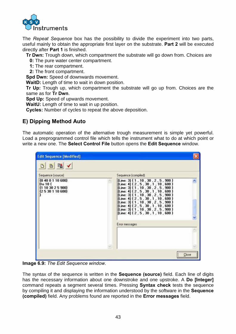
The automatic operation of the alternative trough measurement is simple yet powerful. Load a preprogrammed control file which tells the instrument what to do at which point or write a new one. The Select Control File button opens the Edit Sequence window.
Image 6.9: The Edit Sequence window. The syntax of the sequence is written in the Sequence (source) field. Each line of digits has the necessary information about one downstroke and one upstroke. A Do [Integer] command repeats a segment several times. Pressing Syntax check tests the sequence by compiling it and displaying the information understood by the software in the Sequence (compiled) field. Any problems found are reported in the Error messages field.
44
The basic command line consists of six numbers separated by spaces.
{A B C D E F} Every line of numbers must start with { and end with }. The different numbers stand for the following parameters: A: Compartment to enter from (0 is the center, 1 is the rear and 2 is the front). B: Speed of downstroke in mm/min. C: Time to wait after downstroke in s. D: Compartment to exit from (0 is the center, 1 is the rear and 2 is the front). E:Speed of upstroke in mm/min. F: Time to wait after upstroke in s. Thus the sequence for first entering the rear compartment of the trough at 10mm/min and after 30s lifting up from the front compartment at 5mm/min for a wait of 5 minutes would be:
{1 10 30 2 5 300} Many depositions are performed with hydrophilic substrates. The first layer must be deposited with the substrate rising from below the surface so the substrate needs to be inserted through the pure water of the center compartment. This can be done at a relatively high speed with no subsequent wait necessary. For example the sequence to deposit a monolayer from the rear compartment at 10mm/min and allowing the substrate to dry for 10 minutes would be:
{0 40 0 1 10 600} This could be followed by five successive deposition cycles where the substrate enters the front trough at a rate of 5mm/min, waits 30s and is pulled up from the rear trough at 10mm/min for a wait of 20s then the entire sequence would be:
{0 40 0 1 10 600} Do 5 { {2 5 30 1 10 20} }
An alternative deposition cycle could be done to obtain bilayers of two substances. After the initial monolayer from the rear trough has dried the substrate is immersed in the rear trough again and withdrawn from the front trough. The substrate is then immersed in the front trough and withdrawn from the rear trough. This can be repeated as many times as necessary. To obtain a bilayer on the last deposition cycle the substrate needs to be pulled up from the center compartment.
{0 40 0 1 10 600} Do 10 { {1 10 30 2 5 900} {2 5 30 1 10 600} } {1 10 30 0 10 20}
45
6.4. Compression Isotherm Measurement A) General Advice
If there is no way to check the concentration of the solution (for example by UV-vis spectrography) always use freshly made samples from pure stock solutions.
When investigating surfactants with high (>60mN/m) collapsing pressures the level of the subphase is especially important. If the level is too high the monolayer can be pushed over the edge of the trough. If the level is too low the monolayer can leak under the barriers. With hydrophilic barriers the level of the subphase should be the same as the level of the trough edges.
The Appendix at the end of this manual gives examples of experiments along with their instructions that can be operated with a LB device. It is highly recommended to new users to read the appendix and to perform some of the experiments described there.
With expensive surfactants it is preferable to attempt new experiments with a cheap surfactant such as stearic acid first to verify the procedure.
Allow enough time (10...20min) for the temperature to stabilize before beginning a measurement.
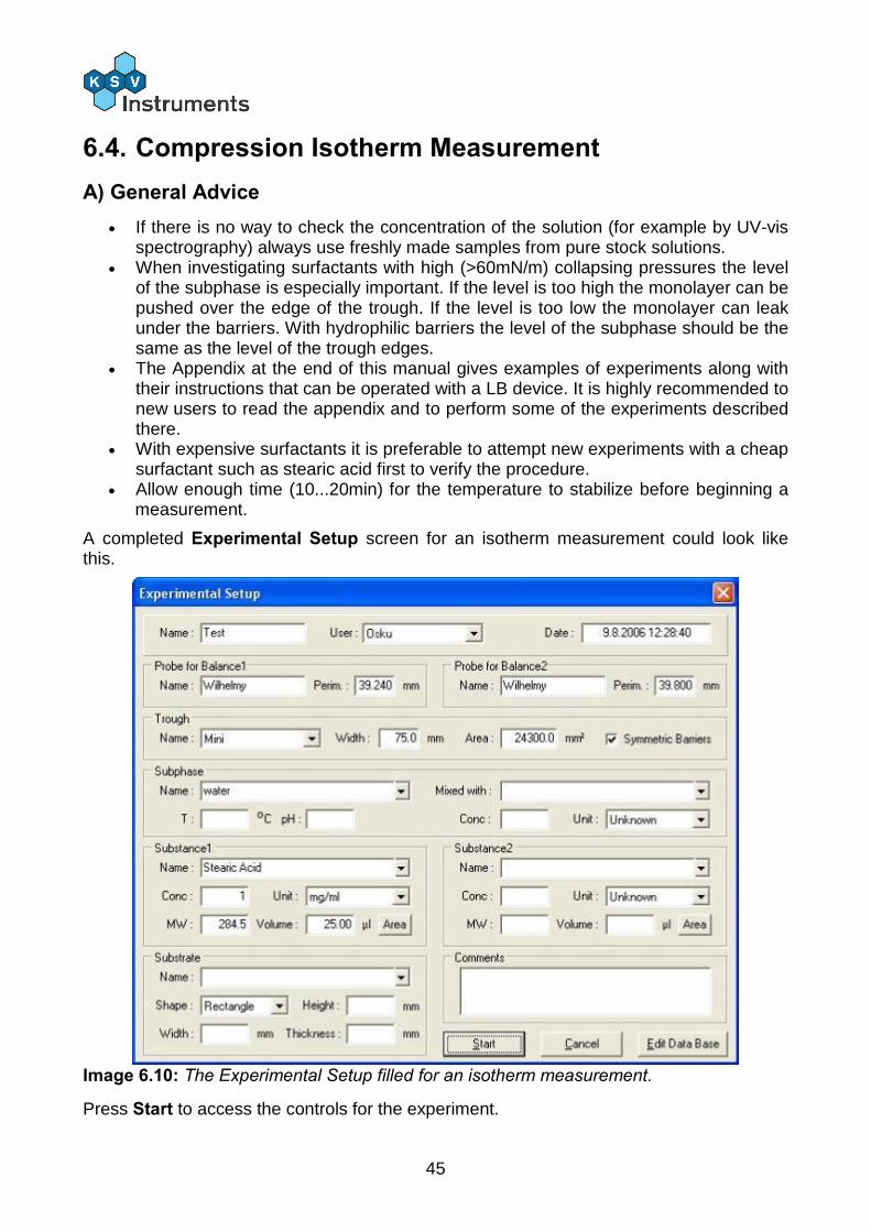
A completed Experimental Setup screen for an isotherm measurement could look like this.
Image 6.10: The Experimental Setup filled for an isotherm measurement.
Press Start to access the controls for the experiment.
46
B) Measurement
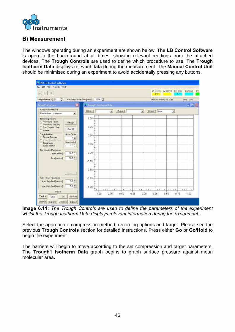
The windows operating during an experiment are shown below. The LB Control Software is open in the background at all times, showing relevant readings from the attached devices. The Trough Controls are used to define which procedure to use. The Trough Isotherm Data displays relevant data during the measurement. The Manual Control Unit should be minimised during an experiment to avoid accidentally pressing any buttons.
Image 6.11: The Trough Controls are used to define the parameters of the experiment whilst the Trough Isotherm Data displays relevant information during the experiment. . Select the appropriate compression method, recording options and target. Please see the previous Trough Controls section for detailed instructions. Press either Go or Go/Hold to begin the experiment. The barriers will begin to move according to the set compression and target parameters. The Trough1 Isotherm Data graph begins to graph surface pressure against mean molecular area.
47
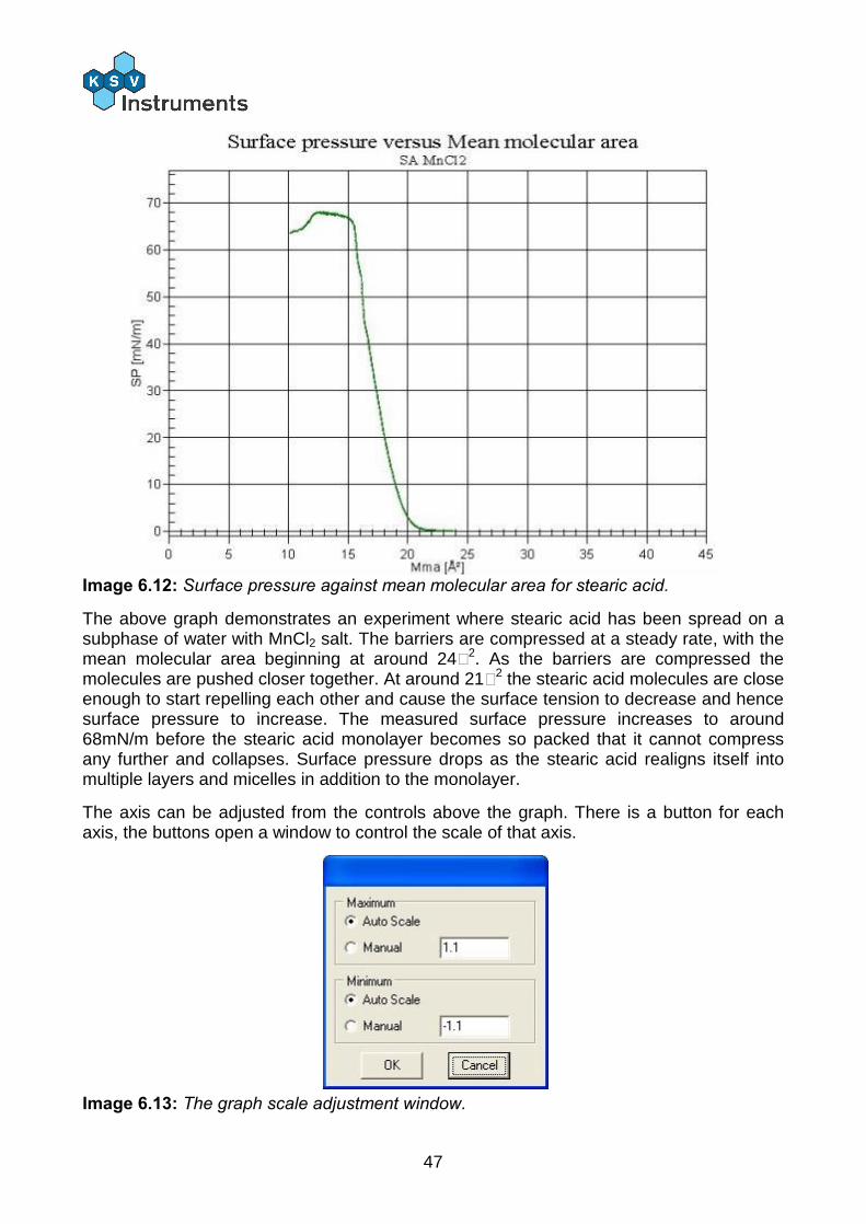
Image 6.12: Surface pressure against mean molecular area for stearic acid.
The above graph demonstrates an experiment where stearic acid has been spread on a subphase of water with MnCl2 salt. The barriers are compressed at a steady rate, with the mean molecular area beginning at around 24Å2. As the barriers are compressed the molecules are pushed closer together. At around 21Å2 the stearic acid molecules are close enough to start repelling each other and cause the surface tension to decrease and hence surface pressure to increase. The measured surface pressure increases to around 68mN/m before the stearic acid monolayer becomes so packed that it cannot compress any further and collapses. Surface pressure drops as the stearic acid realigns itself into multiple layers and micelles in addition to the monolayer.
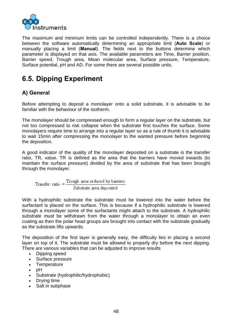
The axis can be adjusted from the controls above the graph. There is a button for each axis, the buttons open a window to control the scale of that axis.
Image 6.13: The graph scale adjustment window.
48
The maximum and minimum limits can be controlled independently. There is a choice between the software automatically determining an appropriate limit (Auto Scale) or manually placing a limit (Manual). The fields next to the buttons determine which parameter is displayed on that axis. The available parameters are Time, Barrier position, Barrier speed, Trough area, Mean molecular area, Surface pressure, Temperature, Surface potential, pH and AD. For some there are several possible units.
6.5. Dipping Experiment
A) General
Before attempting to deposit a monolayer onto a solid substrate, it is advisable to be familiar with the behaviour of the isotherm. The monolayer should be compressed enough to form a regular layer on the substrate, but not too compressed to risk collapse when the substrate first touches the surface. Some monolayers require time to arrange into a regular layer so as a rule of thumb it is advisable to wait 15min after compressing the monolayer to the wanted pressure before beginning the deposition. A good indicator of the quality of the monolayer deposited on a substrate is the transfer ratio, TR, value. TR is defined as the area that the barriers have moved inwards (to maintain the surface pressure) divided by the area of substrate that has been brought through the monolayer.
With a hydrophilic substrate the substrate must be lowered into the water before the surfactant is placed on the surface. This is because if a hydrophilic substrate is lowered through a monolayer some of the surfactants might attach to the substrate. A hydrophilic substrate must be withdrawn from the water through a monolayer to obtain an even coating as then the polar head groups are brought into contact with the substrate gradually as the substrate lifts upwards. The deposition of the first layer is generally easy, the difficulty lies in placing a second layer on top of it. The substrate must be allowed to properly dry before the next dipping. There are various variables that can be adjusted to improve results
Dipping speed Surface pressure Temperature pH Substrate (hydrophilic/hydrophobic) Drying time Salt in subphase
49
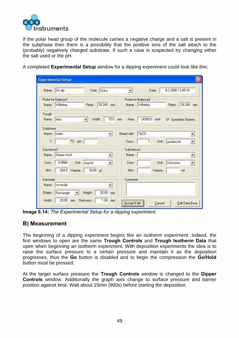
If the polar head group of the molecule carries a negative charge and a salt is present in the subphase then there is a possibility that the positive ions of the salt attach to the (probably) negatively charged substrate. If such a case is suspected try changing either the salt used or the pH. A completed Experimental Setup window for a dipping experiment could look like this:
Image 6.14: The Experimental Setup for a dipping experiment.
B) Measurement
The beginning of a dipping experiment begins like an isotherm experiment. Indeed, the first windows to open are the same Trough Controls and Trough Isotherm Data that open when beginning an isotherm experiment. With deposition experiments the idea is to raise the surface pressure to a certain pressure and maintain it as the deposition progresses, thus the Go button is disabled and to begin the compression the Go/Hold button must be pressed. At the target surface pressure the Trough Controls window is changed to the Dipper Controls window. Additionally the graph axis change to surface pressure and barrier position against time. Wait about 15min (900s) before starting the deposition.
50
6.6. Alternate Dipping Experiment A) General The alternate dipping trough consists of three compartments. The center compartment is a clean water surface, whilst the front and the rear compartments can have separate surfactants and surface pressures. One dipper arm operates above the surface and one below the surface. The motions of the substrate can be precisely controlled, immersing into the subphase in one compartment and emerging from another.
An alternate dipping experiment controls the surface pressure of two independent trough compartments, with two balances and a dipper with two arms. If the substrate is large the speed of the dipper can be adjusted from the Device Parameters window. Please see the Device Parameters section for details.
The first time the alternate dipper is used be sure to check that the Device Parameters have been correctly set!
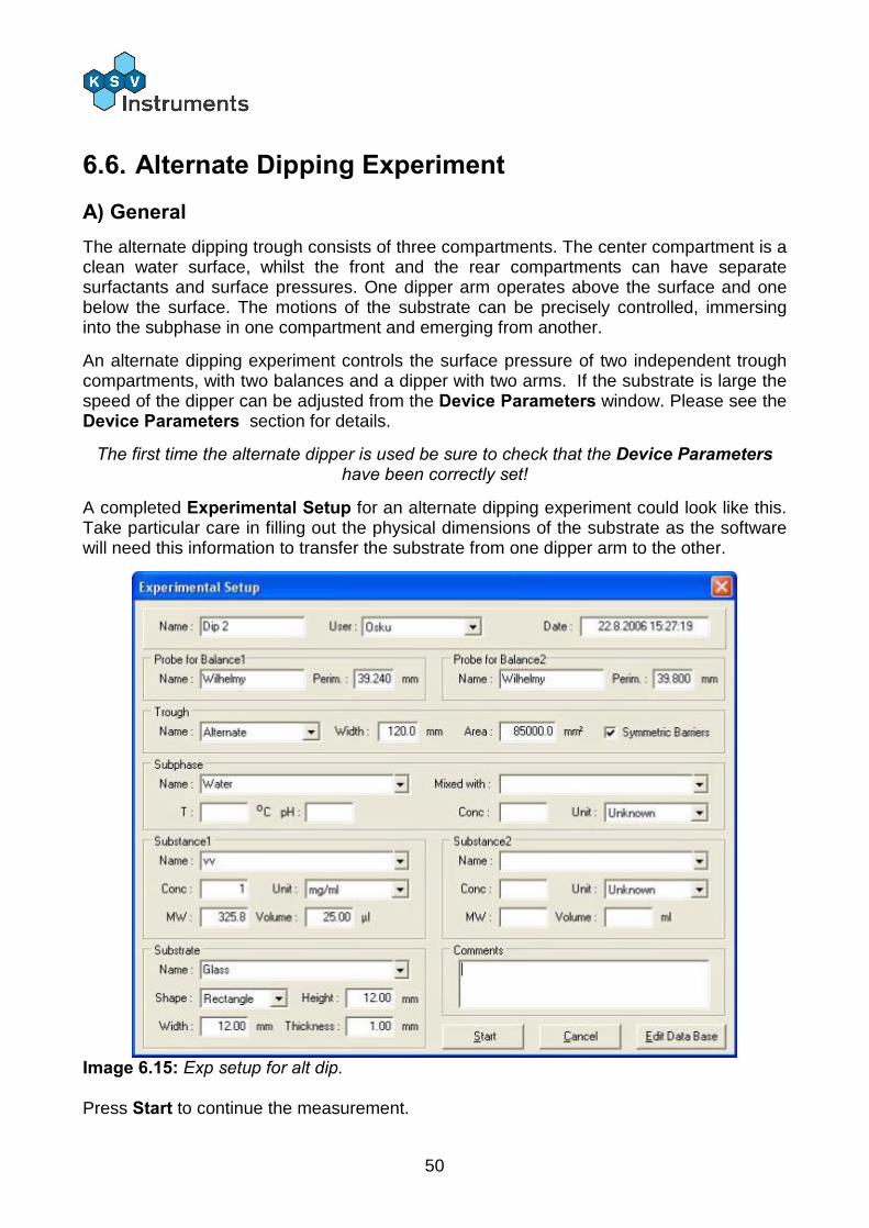
A completed Experimental Setup for an alternate dipping experiment could look like this. Take particular care in filling out the physical dimensions of the substrate as the software will need this information to transfer the substrate from one dipper arm to the other.
Image 6.15: Exp setup for alt dip. Press Start to continue the measurement.
51
B) Measurement
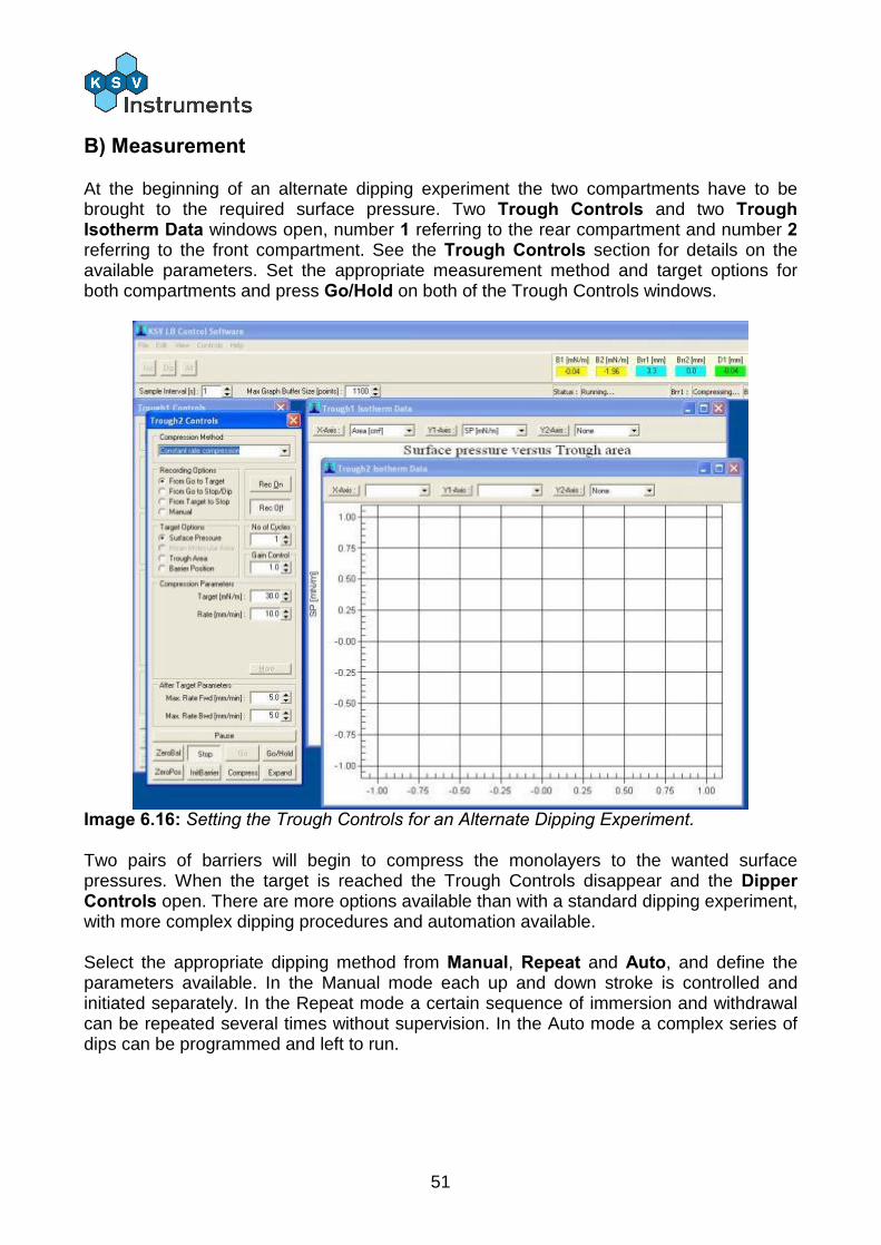
At the beginning of an alternate dipping experiment the two compartments have to be brought to the required surface pressure. Two Trough Controls and two Trough Isotherm Data windows open, number 1 referring to the rear compartment and number 2 referring to the front compartment. See the Trough Controls section for details on the available parameters. Set the appropriate measurement method and target options for both compartments and press Go/Hold on both of the Trough Controls windows.
Image 6.16: Setting the Trough Controls for an Alternate Dipping Experiment. Two pairs of barriers will begin to compress the monolayers to the wanted surface pressures. When the target is reached the Trough Controls disappear and the Dipper Controls open. There are more options available than with a standard dipping experiment, with more complex dipping procedures and automation available. Select the appropriate dipping method from Manual, Repeat and Auto, and define the parameters available. In the Manual mode each up and down stroke is controlled and initiated separately. In the Repeat mode a certain sequence of immersion and withdrawal can be repeated several times without supervision. In the Auto mode a complex series of dips can be programmed and left to run.
52
7. Data Reduction and Analysis 7.1. Overview
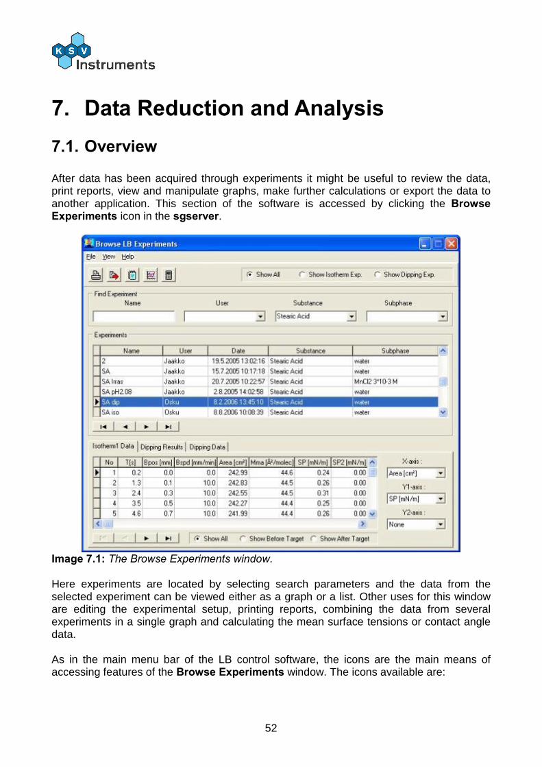
After data has been acquired through experiments it might be useful to review the data, print reports, view and manipulate graphs, make further calculations or export the data to another application. This section of the software is accessed by clicking the Browse Experiments icon in the sgserver.
Image 7.1: The Browse Experiments window. Here experiments are located by selecting search parameters and the data from the selected experiment can be viewed either as a graph or a list. Other uses for this window are editing the experimental setup, printing reports, combining the data from several experiments in a single graph and calculating the mean surface tensions or contact angle data. As in the main menu bar of the LB control software, the icons are the main means of accessing features of the Browse Experiments window. The icons available are:
53
Print: Prints a report of experiment
Copy Data: Copies data to clipboard for export
Experimental Setup: Opens the Experimental Setup window for editing
View Graph: Review the graph of the data which was opened last
View Calculated Results: Opens the Calculations window The uses of the icons are explained more thoroughly below.
7.2. Locating an Experiment
Locating the experiment wanted is crucial when many experiments are available. In the Experiments box all of the experiments that have been conducted are visible. To help reduce the number of displayed measurements several parameters can be set. In the top right corner is an experiment type selector. The options available are Show All, Show Isotherm Exp and Show Dipping Exp. Below them is the main search engine. The fields can be narrowed down as much as is necessary and the experiments that fit all of the parameters are show below them. The available search fields are: Name, User, Substance and Subphase. Use the scroll buttons to find the desired experiment from the results of the search. Display the data from the desired experiment by double-clicking on it with the mouse. The tabs at the bottom of the screen lists information from any troughs or depositions undertaken. The tab which is open is the one from which data is taken for graphing. The columns of data in an Isotherm Data are as follows: No: Number of datapoint Time (s): Time at which data was recorded in seconds. Bpos (mm): Barrier position from zero position in mm. Bspd (mm/min): Barrier speed in mm/min. Area (cm2): Area between barriers in cm2. Mma (Å2/mol): Area per molecule in Å2/mol. SP (mN/mm): Surface pressure reading in mN/mm. SP2 (mN/mm): Surface pressure reading from balance 2 if available in mN/mm. T (C): Temperature in degrees Celsius. SP (V): Surface potential in volts. Ph: pH of liquid. AD (V): Reading from analogue device. Additionally there is a field at the bottom of the window that controls what data is shown in the list above as well as in the graph. The choice is whether to limit the data shown to before the target value was reached, after the target value was reached or not to limit the data at all.
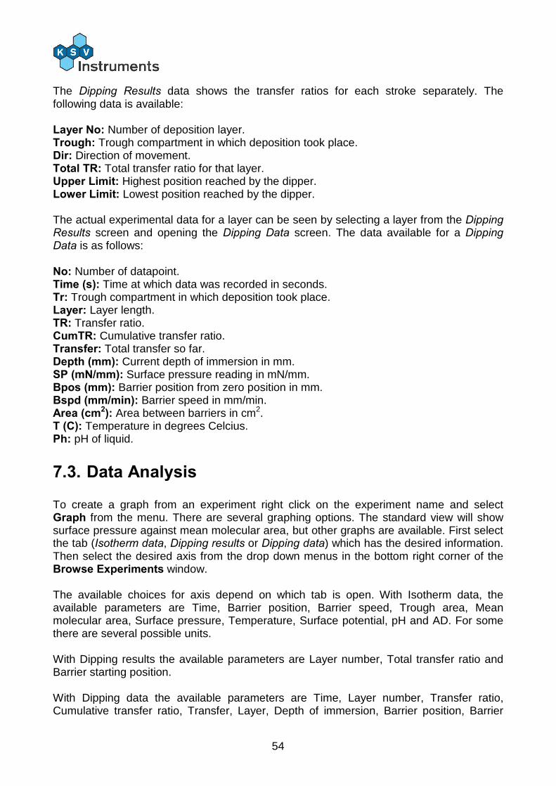
54
The Dipping Results data shows the transfer ratios for each stroke separately. The following data is available: Layer No: Number of deposition layer. Trough: Trough compartment in which deposition took place. Dir: Direction of movement. Total TR: Total transfer ratio for that layer. Upper Limit: Highest position reached by the dipper. Lower Limit: Lowest position reached by the dipper. The actual experimental data for a layer can be seen by selecting a layer from the Dipping Results screen and opening the Dipping Data screen. The data available for a Dipping Data is as follows: No: Number of datapoint. Time (s): Time at which data was recorded in seconds. Tr: Trough compartment in which deposition took place. Layer: Layer length. TR: Transfer ratio. CumTR: Cumulative transfer ratio. Transfer: Total transfer so far. Depth (mm): Current depth of immersion in mm. SP (mN/mm): Surface pressure reading in mN/mm. Bpos (mm): Barrier position from zero position in mm. Bspd (mm/min): Barrier speed in mm/min. Area (cm2): Area between barriers in cm2. T (C): Temperature in degrees Celcius. Ph: pH of liquid.
7.3. Data Analysis
To create a graph from an experiment right click on the experiment name and select Graph from the menu. There are several graphing options. The standard view will show surface pressure against mean molecular area, but other graphs are available. First select the tab (Isotherm data, Dipping results or Dipping data) which has the desired information. Then select the desired axis from the drop down menus in the bottom right corner of the Browse Experiments window. The available choices for axis depend on which tab is open. With Isotherm data, the available parameters are Time, Barrier position, Barrier speed, Trough area, Mean molecular area, Surface pressure, Temperature, Surface potential, pH and AD. For some there are several possible units. With Dipping results the available parameters are Layer number, Total transfer ratio and Barrier starting position. With Dipping data the available parameters are Time, Layer number, Transfer ratio, Cumulative transfer ratio, Transfer, Layer, Depth of immersion, Barrier position, Barrier
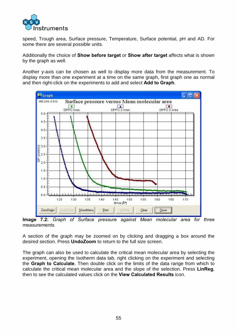
55
speed, Trough area, Surface pressure, Temperature, Surface potential, pH and AD. For some there are several possible units. Additionally the choice of Show before target or Show after target affects what is shown by the graph as well. Another y-axis can be chosen as well to display more data from the measurement. To display more than one experiment at a time on the same graph, first graph one as normal and then right-click on the experiments to add and select Add to Graph.
Image 7.2: Graph of Surface pressure against Mean molecular area for three measurements. A section of the graph may be zoomed on by clicking and dragging a box around the desired section. Press UndoZoom to return to the full size screen. The graph can also be used to calculate the critical mean molecular area by selecting the experiment, opening the Isotherm data tab, right clicking on the experiment and selecting the Graph to Calculate. Then double click on the limits of the data range from which to calculate the critical mean molecular area and the slope of the selection. Press LinReg, then to see the calculated values click on the View Calculated Results icon.
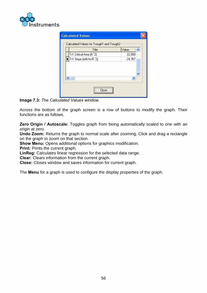
56
Image 7.3: The Calculated Values window. Across the bottom of the graph screen is a row of buttons to modify the graph. Their functions are as follows. Zero Origin / Autoscale: Toggles graph from being automatically scaled to one with an origin at zero. Undo Zoom: Returns the graph to normal scale after zooming. Click and drag a rectangle on the graph to zoom on that section. Show Menu: Opens additional options for graphics modification. Print: Prints the current graph. LinReg: Calculates linear regression for the selected data range. Clear: Clears information from the current graph. Close: Closes window and saves information for current graph. The Menu for a graph is used to configure the display properties of the graph.
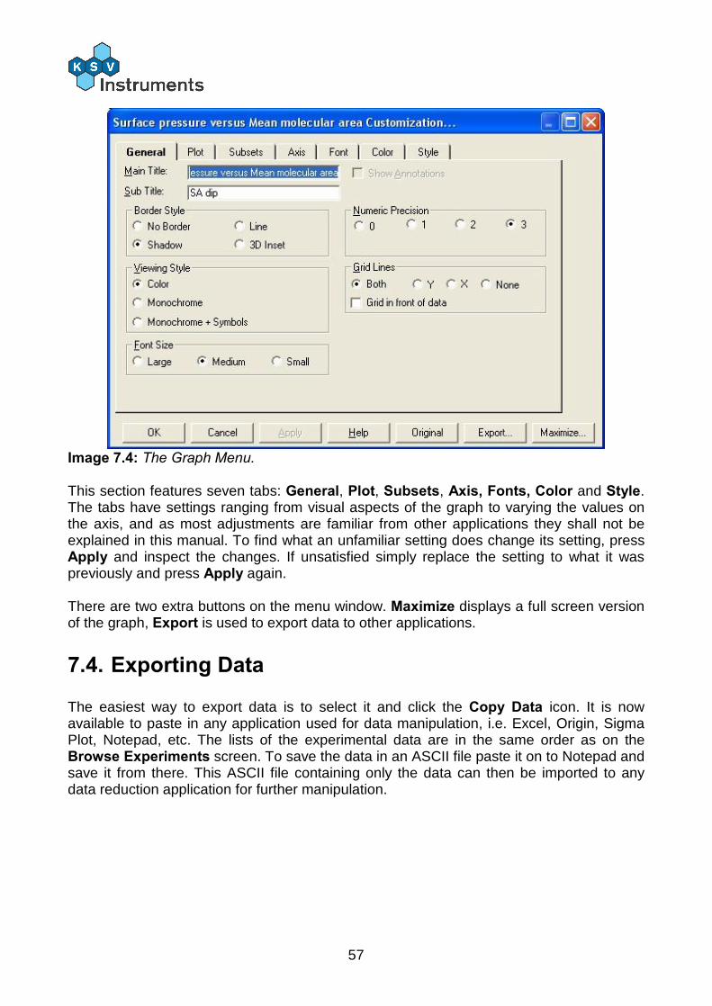
57
Image 7.4: The Graph Menu.
This section features seven tabs: General, Plot, Subsets, Axis, Fonts, Color and Style. The tabs have settings ranging from visual aspects of the graph to varying the values on the axis, and as most adjustments are familiar from other applications they shall not be explained in this manual. To find what an unfamiliar setting does change its setting, press Apply and inspect the changes. If unsatisfied simply replace the setting to what it was previously and press Apply again. There are two extra buttons on the menu window. Maximize displays a full screen version of the graph, Export is used to export data to other applications.
7.4. Exporting Data
The easiest way to export data is to select it and click the Copy Data icon. It is now available to paste in any application used for data manipulation, i.e. Excel, Origin, Sigma Plot, Notepad, etc. The lists of the experimental data are in the same order as on the Browse Experiments screen. To save the data in an ASCII file paste it on to Notepad and save it from there. This ASCII file containing only the data can then be imported to any data reduction application for further manipulation.
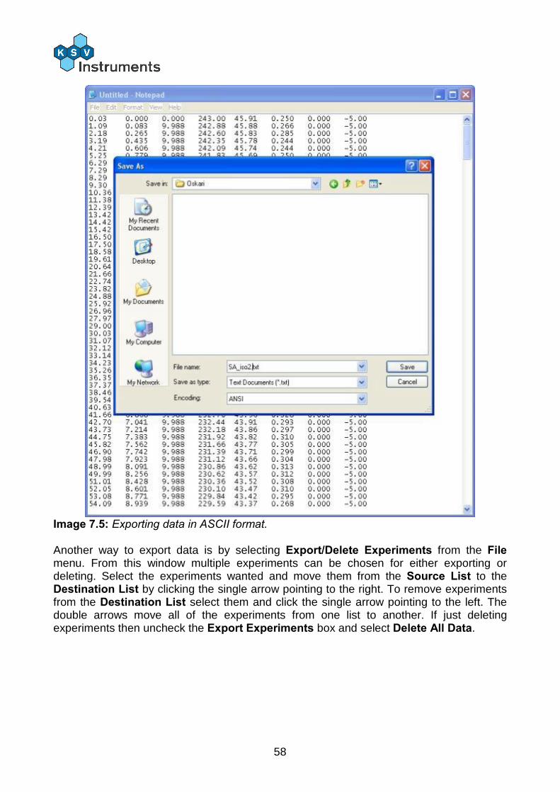
58
Image 7.5: Exporting data in ASCII format. Another way to export data is by selecting Export/Delete Experiments from the File menu. From this window multiple experiments can be chosen for either exporting or deleting. Select the experiments wanted and move them from the Source List to the Destination List by clicking the single arrow pointing to the right. To remove experiments from the Destination List select them and click the single arrow pointing to the left. The double arrows move all of the experiments from one list to another. If just deleting experiments then uncheck the Export Experiments box and select Delete All Data.
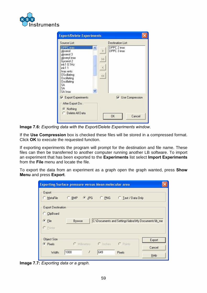
59
Image 7.6: Exporting data with the Export/Delete Experiments window.
If the Use Compression box is checked these files will be stored in a compressed format. Click OK to execute the requested function.
If exporting experiments the program will prompt for the destination and file name. These files can then be transferred to another computer running another LB software. To import an experiment that has been exported to the Experiments list select Import Experiments from the File menu and locate the file.
To export the data from an experiment as a graph open the graph wanted, press Show Menu and press Export.
Image 7.7: Exporting data or a graph.
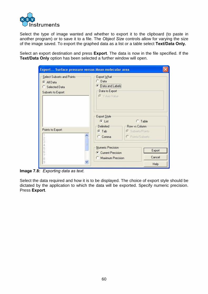
60
Select the type of image wanted and whether to export it to the clipboard (to paste in another program) or to save it to a file. The Object Size controls allow for varying the size of the image saved. To export the graphed data as a list or a table select Text/Data Only. Select an export destination and press Export. The data is now in the file specified. If the Text/Data Only option has been selected a further window will open.
Image 7.8: Exporting data as text. Select the data required and how it is to be displayed. The choice of export style should be dictated by the application to which the data will be exported. Specify numeric precision. Press Export.
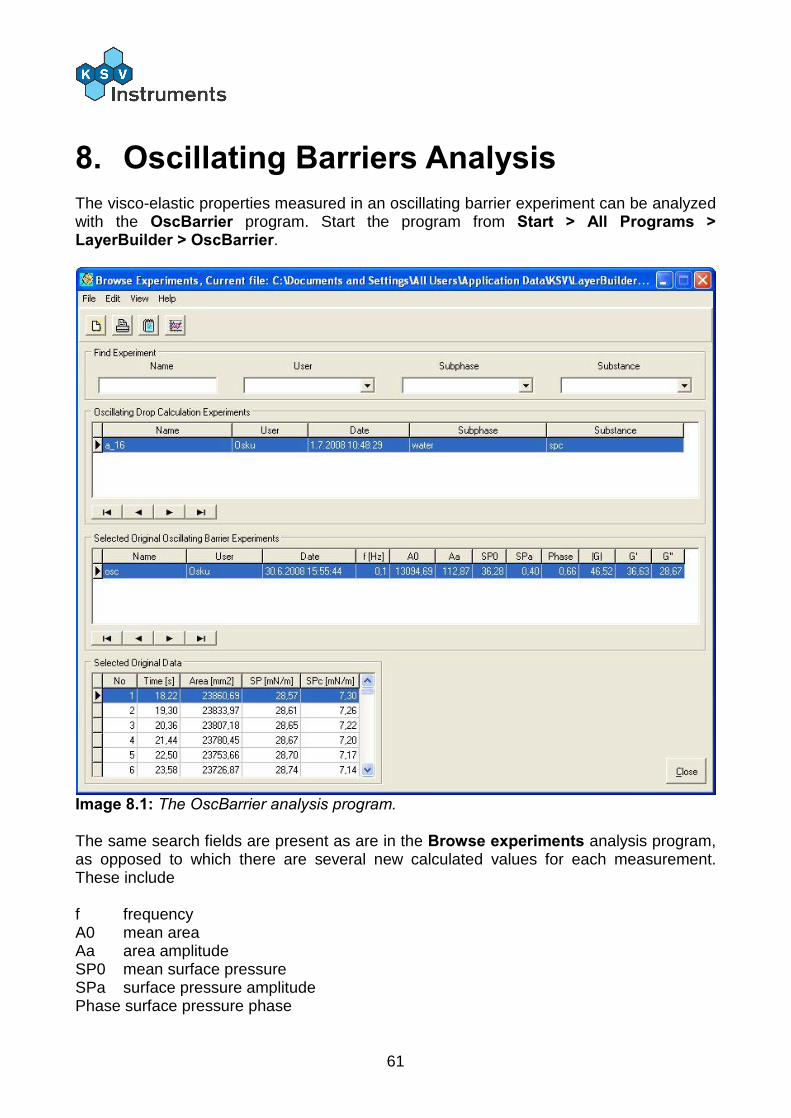
61
8. Oscillating Barriers Analysis The visco-elastic properties measured in an oscillating barrier experiment can be analyzed with the OscBarrier program. Start the program from Start > All Programs > LayerBuilder > OscBarrier.
Image 8.1: The OscBarrier analysis program. The same search fields are present as are in the Browse experiments analysis program, as opposed to which there are several new calculated values for each measurement. These include f frequency A0 mean area Aa area amplitude SP0 mean surface pressure SPa surface pressure amplitude Phase surface pressure phase
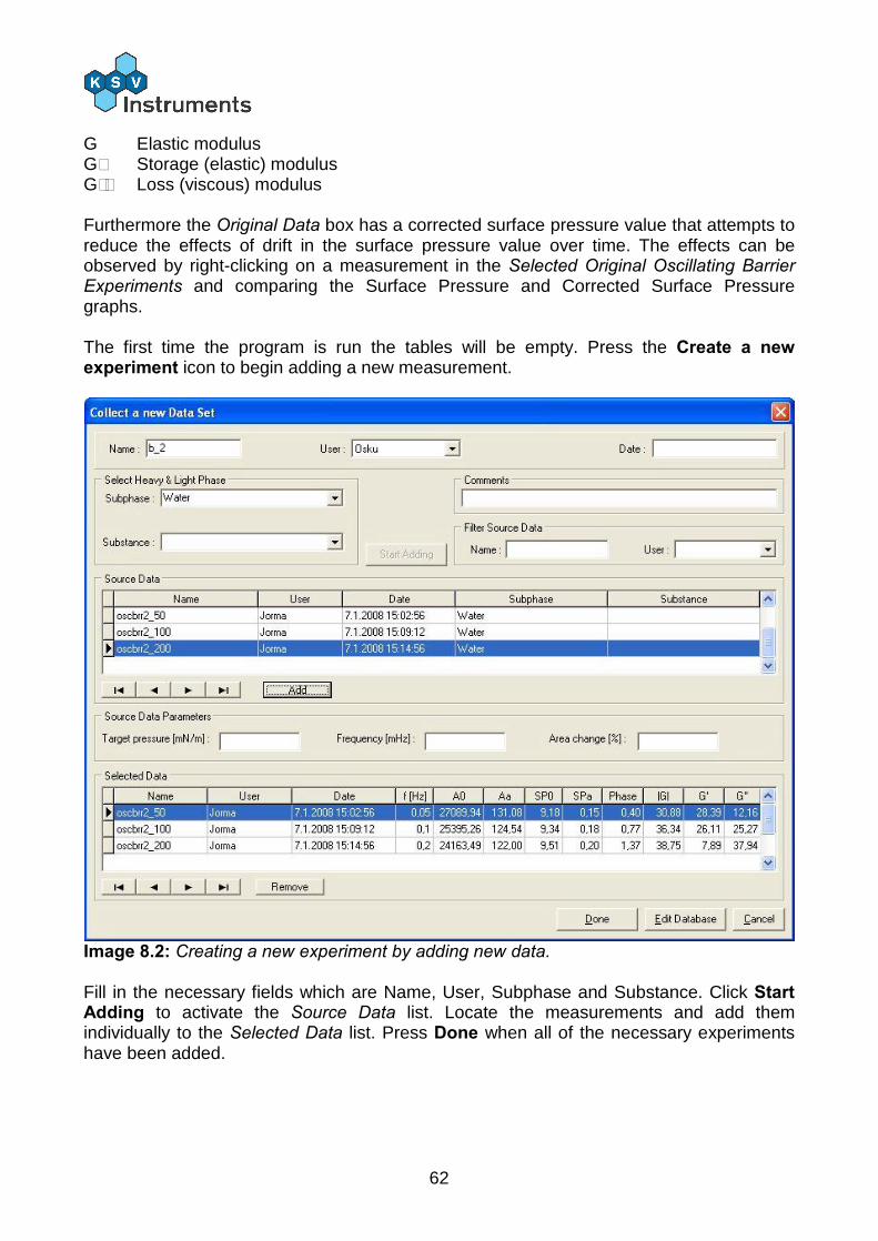
62
G Elastic modulus G´ Storage (elastic) modulus G´´ Loss (viscous) modulus Furthermore the Original Data box has a corrected surface pressure value that attempts to reduce the effects of drift in the surface pressure value over time. The effects can be observed by right-clicking on a measurement in the Selected Original Oscillating Barrier Experiments and comparing the Surface Pressure and Corrected Surface Pressure graphs. The first time the program is run the tables will be empty. Press the Create a new experiment icon to begin adding a new measurement.
Image 8.2: Creating a new experiment by adding new data. Fill in the necessary fields which are Name, User, Subphase and Substance. Click Start Adding to activate the Source Data list. Locate the measurements and add them individually to the Selected Data list. Press Done when all of the necessary experiments have been added.
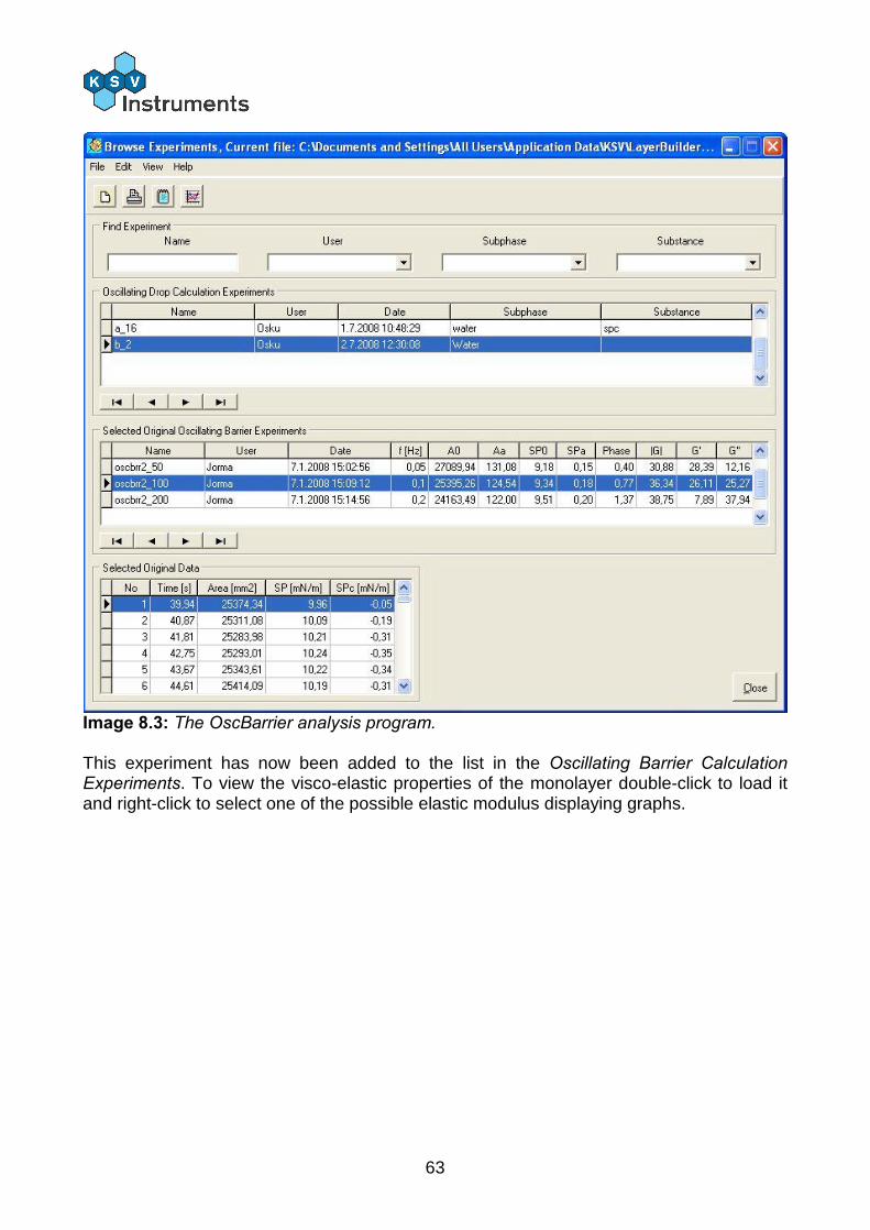
63
Image 8.3: The OscBarrier analysis program. This experiment has now been added to the list in the Oscillating Barrier Calculation Experiments. To view the visco-elastic properties of the monolayer double-click to load it and right-click to select one of the possible elastic modulus displaying graphs.

64
9. Contact Information If any problems arise please feel free to contact a local distributor or KSV Instruments directly. KSV Instruments can be contacted from this address:
KSV Instruments Ltd. Höyläämötie 7 FIN-00380 Helsinki Finland Tel. +358-(0)9-5497 3300 Fax +358-(0)9-5497 3333 E-mail [email protected] for sales and
[email protected] for service or technical questions http://www.ksvltd.com
Local distributors are listed at our website, www.ksvltd.com.
65
Appendix A. Quick Start Guide 1. Monolayer kit
A Monolayer kit is delivered with each LB device. It contains the items necessary to run LB experiments. The delivered components are: 1. Polyethene powder-free gloves 2. Surfactant and lint-free tissues 3. One soft paintbrush for cleaning the trough, and one 50 mm glass beaker for the cleaning solution 4. Aspirator that can be attached to a tap, equipped with rubber tubing and disposable polypropylene tips for cleaning the subphase surface 5. Spatula for preparing monolayer sample and subphase solutions 6. 3 pcs of 5 ml glass tubes for sample and cleaning solutions 7. Microliter syringe (50 ìl) for use for spreading monolayer material 8. 100 pcs of glass slides for LB deposition purposes, 20 mm x 20 mm 9. Tweezers for glass slides 10. Wilhelmy plate of Platinum 11. 100 pcs of Wilhelmy plates made of paper + hook 12. Calibration weight for calibration of the balance 13. Leveling tool for leveling the instrument 14. Tool set
2. Laboratory requirements
The laboratory in which the instrument is placed must meet the following requirements: 1. At least 1.5 x 1.5 m free bench space in a sufficiently clean, draught and dust free environment 2. Running water and a sink (max. 2.5 m from the instrument) to connect the aspirator pump. Alternatively, a vacuum pump and flask can be used. 3. A supply of pure de-ionized and organic free water for cleaning the trough and preparing the subphase. Resistance should be more than 18MOHm cm and TOC levels should be less than 10 ppb. 4. Laboratory balance with minimum accuracy of 0.1 mg. 5. Monolayer material (for example Stearic acid or DPPC). 6. Some metal salt to dissolve in the subphase (preferably CdCl2, MnCl2 or TbCl3). 7. Volatile solvents for preparing the spreading solution of the monolayer material (for example Hexane, Chloroform, or Methane). 8. Pure ethanol for cleaning purposes. 9. Computer running Windows 2000/XP/Vista equipped with the KSV Win LB software for controlling the instrument.
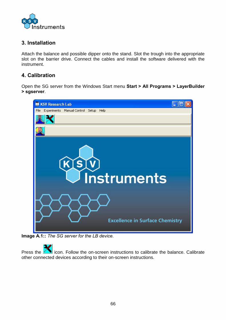
66
3. Installation
Attach the balance and possible dipper onto the stand. Slot the trough into the appropriate slot on the barrier drive. Connect the cables and install the software delivered with the instrument.
4. Calibration
Open the SG server from the Windows Start menu Start > All Programs > LayerBuilder > sgserver.
Image A.1:: The SG server for the LB device.
Press the icon. Follow the on-screen instructions to calibrate the balance. Calibrate other connected devices according to their on-screen instructions.
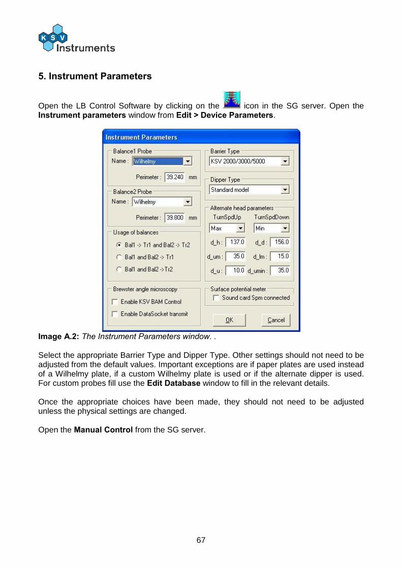
67
5. Instrument Parameters
Open the LB Control Software by clicking on the icon in the SG server. Open the Instrument parameters window from Edit > Device Parameters.
Image A.2: The Instrument Parameters window. . Select the appropriate Barrier Type and Dipper Type. Other settings should not need to be adjusted from the default values. Important exceptions are if paper plates are used instead of a Wilhelmy plate, if a custom Wilhelmy plate is used or if the alternate dipper is used. For custom probes fill use the Edit Database window to fill in the relevant details. Once the appropriate choices have been made, they should not need to be adjusted unless the physical settings are changed. Open the Manual Control from the SG server.
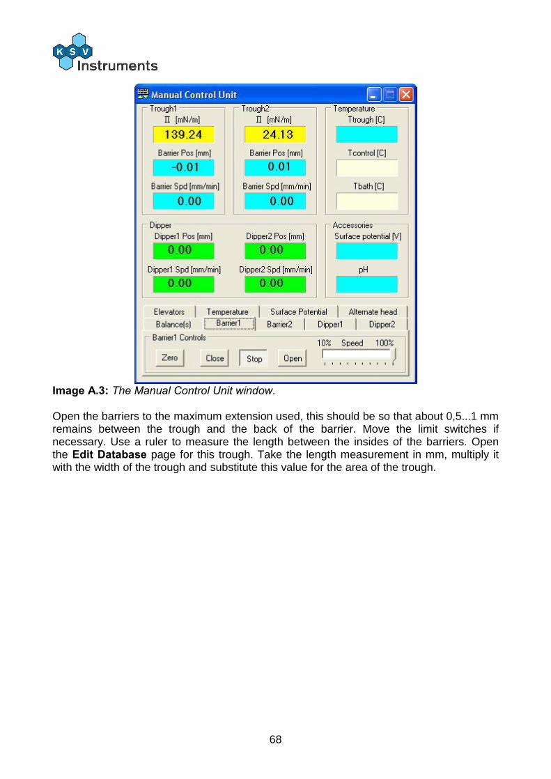
68
Image A.3: The Manual Control Unit window. Open the barriers to the maximum extension used, this should be so that about 0,5...1 mm remains between the trough and the back of the barrier. Move the limit switches if necessary. Use a ruler to measure the length between the insides of the barriers. Open the Edit Database page for this trough. Take the length measurement in mm, multiply it with the width of the trough and substitute this value for the area of the trough.
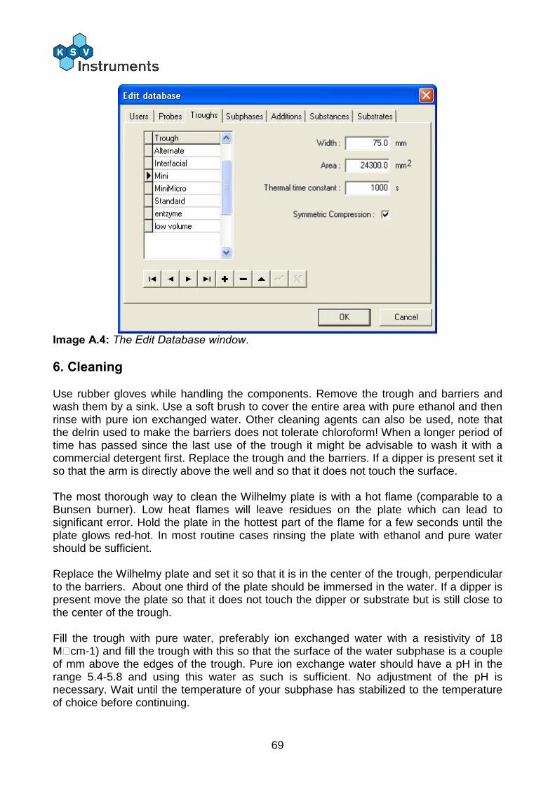
69
Image A.4: The Edit Database window.
6. Cleaning
Use rubber gloves while handling the components. Remove the trough and barriers and wash them by a sink. Use a soft brush to cover the entire area with pure ethanol and then rinse with pure ion exchanged water. Other cleaning agents can also be used, note that the delrin used to make the barriers does not tolerate chloroform! When a longer period of time has passed since the last use of the trough it might be advisable to wash it with a commercial detergent first. Replace the trough and the barriers. If a dipper is present set it so that the arm is directly above the well and so that it does not touch the surface. The most thorough way to clean the Wilhelmy plate is with a hot flame (comparable to a Bunsen burner). Low heat flames will leave residues on the plate which can lead to significant error. Hold the plate in the hottest part of the flame for a few seconds until the plate glows red-hot. In most routine cases rinsing the plate with ethanol and pure water should be sufficient. Replace the Wilhelmy plate and set it so that it is in the center of the trough, perpendicular to the barriers. About one third of the plate should be immersed in the water. If a dipper is present move the plate so that it does not touch the dipper or substrate but is still close to the center of the trough. Fill the trough with pure water, preferably ion exchanged water with a resistivity of 18 MÙcm-1) and fill the trough with this so that the surface of the water subphase is a couple of mm above the edges of the trough. Pure ion exchange water should have a pH in the range 5.4-5.8 and using this water as such is sufficient. No adjustment of the pH is necessary. Wait until the temperature of your subphase has stabilized to the temperature of choice before continuing.
70
Open the Manual Control from the SG server and start moving the barriers together slowly and run an aspirator over the surface inside the barriers. This procedure should be repeated 2-3 times. Check that the limits are set so that the Wilhelmy, dipper substrate or anything else does not touch the barriers when they are at their inside limit. Check the purity of the water by zeroing the value of the balance at the maximum extension of the barriers and then bringing them closer together. If the surface pressure does not go above 0.3 mN/m then it is sufficiently clean.
7. Surfactant
If about to perform a dipping experiment the substrate often needs to first be lifted up through the monolayer. This means that before placing the surfactant the substrate needs to be attached to the dipper and fully immersed into the water. Raise or lower the dipper with the Manual Control. Check that the barriers are open all the way. The surfactant is applied onto the surface of the water in a volatile organic solvent. This solvent evaporates leaving the surfactant on the surface of the water. The most suitable volume and concentration for the surfactant can be found through trial and error. Generally a concentration of 0.5...1 mg/ml is acceptable. With a concentration of 1 mg/ml, the appropriate sample volume depends on the trough, with a KSV Minitrough about 20...25 µl is appropriate whereas with a KSV 2000 trough 60...80 µl is appropriate. Clean a microliter syringe by flushing it with either hexane or chloroform. Shake the container with the sample solution thoroughly. Draw out a drop on the needle and touch the surface of the water with the drop. Be careful not to let the drop fall off the needle, as this increases the chances of the sample being lost to the bulk of the water as opposed to the surface. Additionally the waves created by the landing of the drop can push the surfactants already on the surface towards the barriers and the edges of the trough. Place the solution onto the surface slowly and evenly spread enough that the surface pressure reading does not exceed 0.5 mN/m at any point. The most common spreading solvents are hexane and chloroform. Allow at least 10 min for the solvent to evaporate before beginning the experiment itself.

71
Appendix B. Example Isotherm Experiments There are many varieties of possible experiments. This guide has instructions on three isotherm experiments which should help to demonstrate the use and versatility of the LB device. Two measurements will be performed with stearic acid (SA) and one with Dipalmitoylphosphatidylcholine (DPPC). The idea of the first measurement is to measure the SA isotherm on pure water with a pH of about 5.5 as this isotherm is so well known with clear, distinctive points that can be used as check points to confirm that the measurement is OK. In the second measurements a small amount of a salt is added to the subphase and the effects to the SA isotherm are observed. The third measurement uses DPPC to demonstrate the appearance of a special phase called Liquid Expanded – Liquid Condensed (LE-LC) where a liquid and solid phase co-exist.
SA isotherm on pure water
Clean the trough according to the instructions above. Prepare a sample of 1 mg/ml stearic acid in either hexane or chloroform. Fill the trough with pure water. Check that the barriers are fully open and that the balance is ready to use. Zero the position of the barriers and the value on the balance. It is very important that these values are zeroed before any of sample is placed on the surface. With a KSV Minitrough take about 20 µl of the solution, with a KSV 2000 or 5000 take about 60 µl of the solution. Place the sample on the surface according to the instructions above and allow at least 10 min for the solvent to evaporate before beginning the experiment.
On the SG server press to open the LB Control Software window
Image B.1: The LB Control Software. Press the Iso button. This opens the Experimental Setup window. Fill in the relevant fields, particularly important for analysis are the balance probe, trough area and substance1 properties.
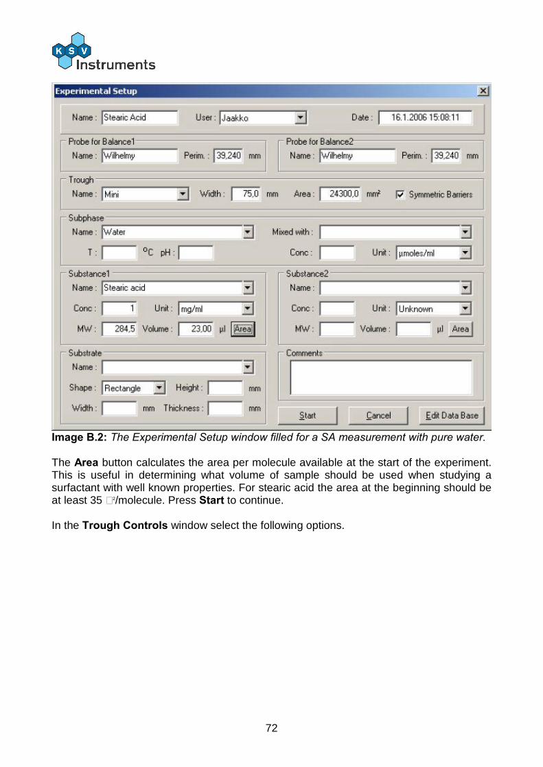
72
Image B.2: The Experimental Setup window filled for a SA measurement with pure water. The Area button calculates the area per molecule available at the start of the experiment. This is useful in determining what volume of sample should be used when studying a surfactant with well known properties. For stearic acid the area at the beginning should be at least 35 Å2/molecule. Press Start to continue. In the Trough Controls window select the following options.
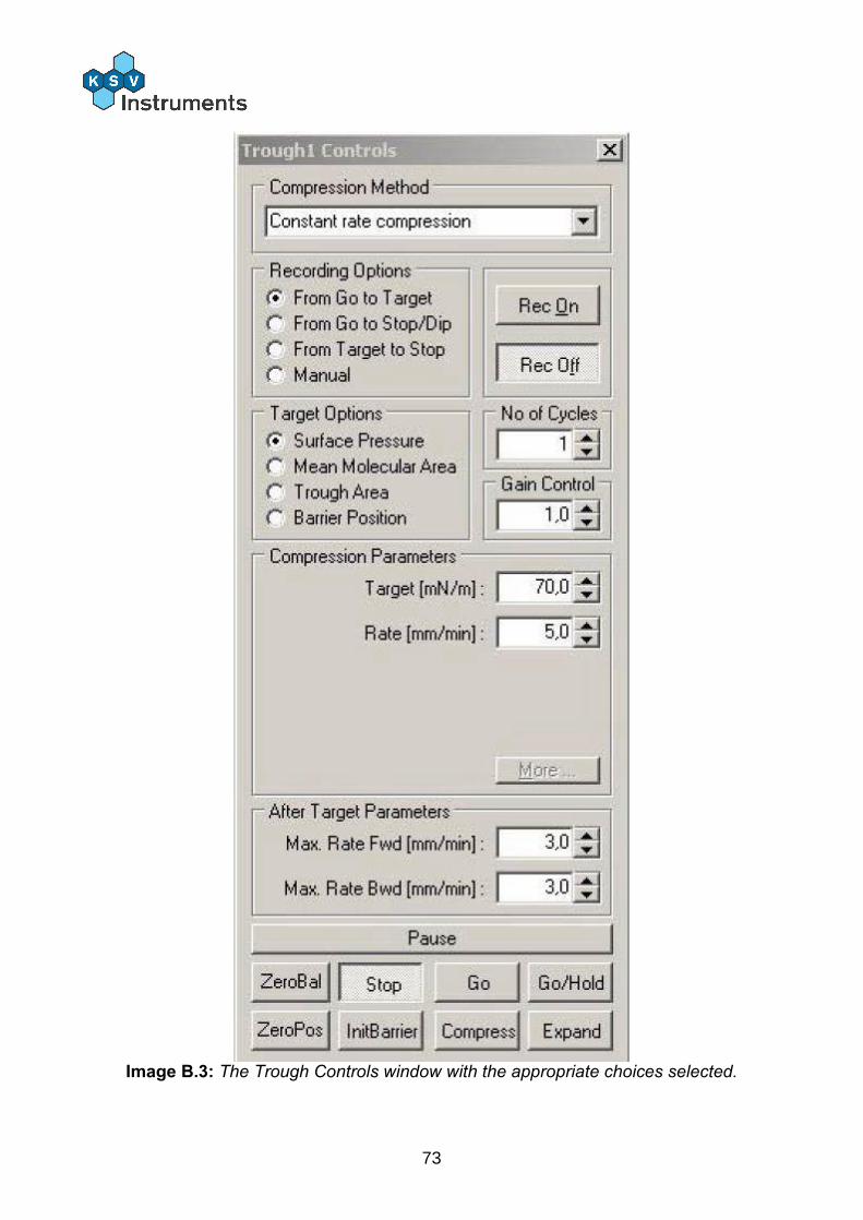
73
Image B.3: The Trough Controls window with the appropriate choices selected.

74
Check that more than 10 min have passed since placing the surfactant solution. Press Go. The barriers move slowly, so do not be alarmed if the motion cannot be noticed immediately.
The target surface pressure is so high that the barriers will close past collapse point of the monolayer. As the surface tension of water is 72.8 mN/m that is the theoretical maximum surface pressure with water as the subphase. The rate should be slow enough to allow the monolayer to reorganise itself, the most common rates are 5...20 mm/min.
The values in the Trough Controls window can be changed during an experiment. The Status bar in the LB Control Software displays what the software is doing at the moment. Once the collapse point has been reached press Stop to end the experiment. The collapse can be seen as either a sudden decrease in surface pressure or as a leveling out a high surface pressure. Here is a typical curve for this experiment.
Image B.4: A typical graph for the isotherm of stearic acid on pure water.
The graph can be split into distinctive regions. While the mean molecular area is above 30 Å2/molecule the molecules are far enough away from each other that they do not significantly interact. This phase is known as the gaseous state. As intermolecular distances decreases the molecules begin to interact and surface pressure begins to rise, here present at mean molecular area of about 20-30 Å2/molecule. This phase is referred to as the liquid state. At a mean molecular area of less than 20 Å2/molecule the molecules are very closely packed and form a rigid layer. This phase is referred to as the solid state.
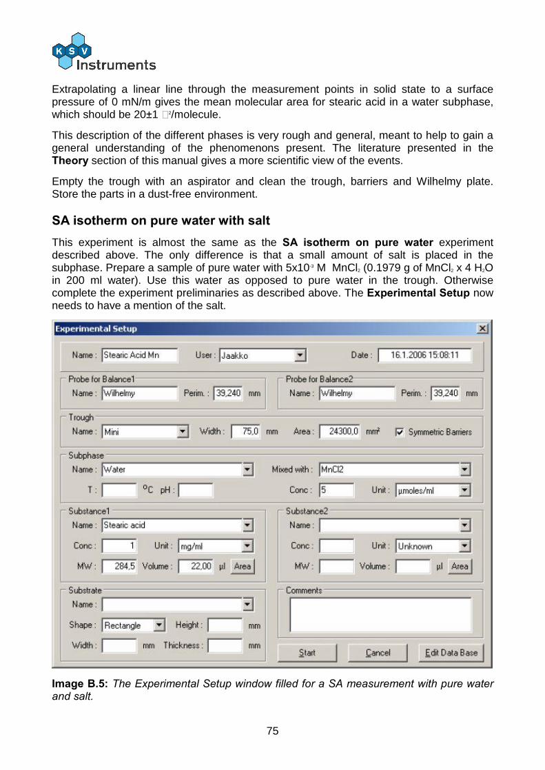
75
Extrapolating a linear line through the measurement points in solid state to a surface pressure of 0 mN/m gives the mean molecular area for stearic acid in a water subphase, which should be 20±1 Å2/molecule.
This description of the different phases is very rough and general, meant to help to gain a general understanding of the phenomenons present. The literature presented in the Theory section of this manual gives a more scientific view of the events.
Empty the trough with an aspirator and clean the trough, barriers and Wilhelmy plate. Store the parts in a dust-free environment.
SA isotherm on pure water with salt This experiment is almost the same as the SA isotherm on pure water experiment described above. The only difference is that a small amount of salt is placed in the subphase. Prepare a sample of pure water with 5x10⁻³ M MnCl2 (0.1979 g of MnCl2 x 4 H2O in 200 ml water). Use this water as opposed to pure water in the trough. Otherwise complete the experiment preliminaries as described above. The Experimental Setup now needs to have a mention of the salt.
Image B.5: The Experimental Setup window filled for a SA measurement with pure water and salt.
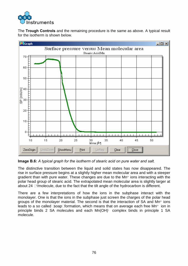
76
The Trough Controls and the remaining procedure is the same as above. A typical result for the isotherm is shown below.
Image B.6: A typical graph for the isotherm of stearic acid on pure water and salt.
The distinctive transition between the liquid and solid states has now disappeared. The rise in surface pressure begins at a slightly higher mean molecular area and with a steeper gradient than with pure water. These changes are due to the Mn2+ ions interacting with the polar head group of stearic acid. The extrapolated mean molecular area is slightly larger at about 24 Å2/molecule, due to the fact that the tilt angle of the hydrocarbon is different.
There are a few interpretations of how the ions in the subphase interact with the monolayer. One is that the ions in the subphase just screen the charges of the polar head groups of the monolayer material. The second is that the interaction of SA and Mn2+ ions leads to a so called “soap” formation, which means that on average each free Mn2+ ion in principle binds 2 SA molecules and each Mn(OH)+ complex binds in principle 1 SA molecule.
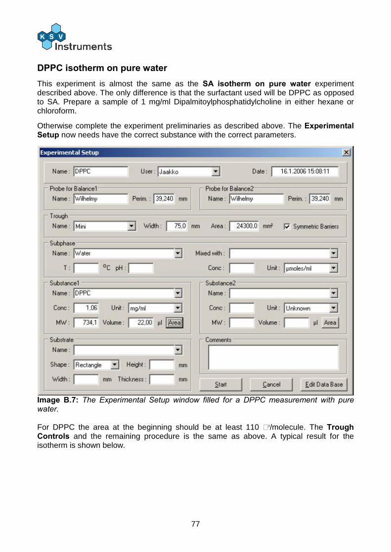
77
DPPC isotherm on pure water This experiment is almost the same as the SA isotherm on pure water experiment described above. The only difference is that the surfactant used will be DPPC as opposed to SA. Prepare a sample of 1 mg/ml Dipalmitoylphosphatidylcholine in either hexane or chloroform.
Otherwise complete the experiment preliminaries as described above. The Experimental Setup now needs have the correct substance with the correct parameters.
Image B.7: The Experimental Setup window filled for a DPPC measurement with pure water. For DPPC the area at the beginning should be at least 110 Å2/molecule. The Trough Controls and the remaining procedure is the same as above. A typical result for the isotherm is shown below.
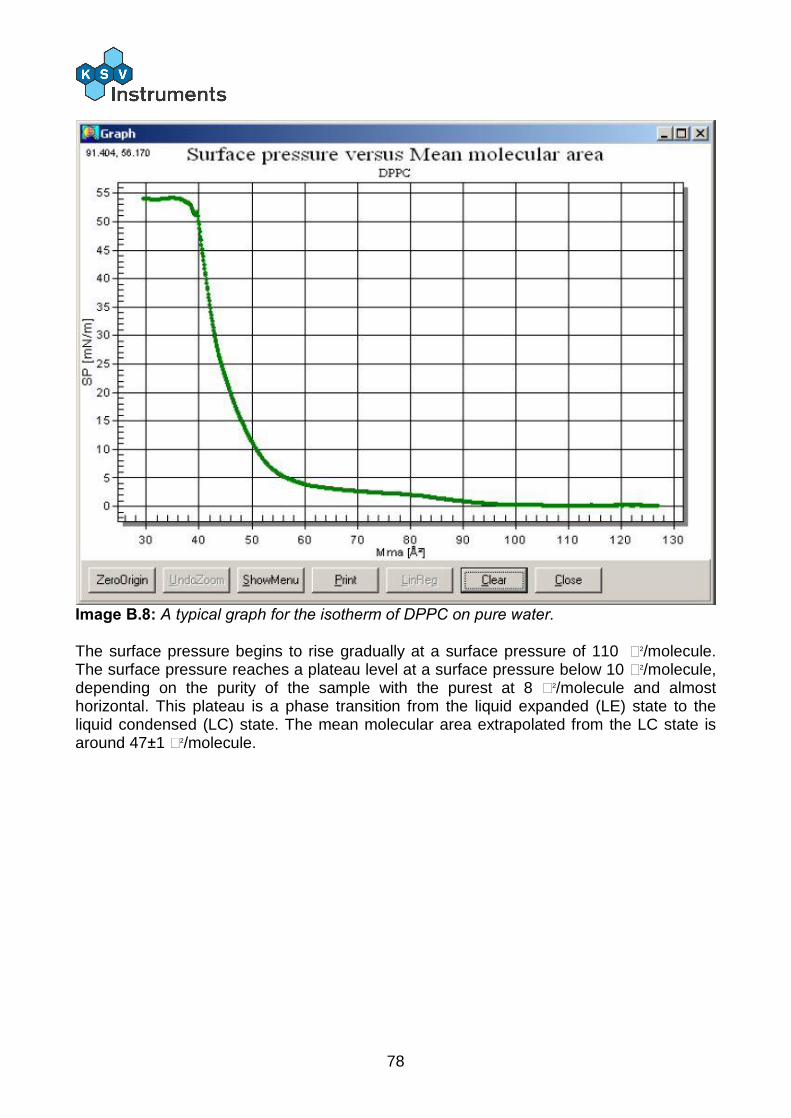
78
Image B.8: A typical graph for the isotherm of DPPC on pure water. The surface pressure begins to rise gradually at a surface pressure of 110 Å2/molecule. The surface pressure reaches a plateau level at a surface pressure below 10 Å2/molecule, depending on the purity of the sample with the purest at 8 Å2/molecule and almost horizontal. This plateau is a phase transition from the liquid expanded (LE) state to the liquid condensed (LC) state. The mean molecular area extrapolated from the LC state is around 47±1 Å2/molecule.

79
Appendix C. Example Dipping Experiment There are many varieties of possible experiments. This guide has instructions on a dipping experiment which should help to demonstrate the use and versatility of the LB device. The idea of the experiment is to prepare a monolayer and use that monolayer to coat multiple layers onto a substrate. Stearic acid is the surfactant used to create the monolayer and the substrate is a glass slide. Multiple depositions require that the subphase has a salt, in this case MnCl2. Clean the glass slide appropriately, e.g. by immersing it in chromic acid or a piranha solution for a few minutes. Other cleaning procedures can also be followed, note that both chromic acid and a piranha solution are highly toxic and corrosive and should be handled with care. Rinse the slide thoroughly with ion-exchanged water and dry the slide by sucking with an aspirator. If the dipper sample holder is attached to the dipper arm remove it with an Allen wrench. Once the slide is dry attach it to the dipper sample holder. Reattach the sample holder onto the dipper arm with an Allen wrench so that the glass slide is parallel with the barriers. The orientation of a substrate in a dipping experiment affects the quality of the deposition, and a parallel orientation leads to the best quality layers. Use the Manual Control to lift the arm well above the level of the surface. Clean the trough according to the instructions above. Prepare a sample of 1 mg/ml stearic acid in either hexane or chloroform. Fill the trough with water and 5x10⁻³ M MnCl2 (0.1979 g of MnCl2 x 4 H2O in 200 ml water). Check that the barriers are fully open and that the balance is ready to use. Zero the position of the barriers and the value on the balance. Lower the dipper slowly, and stop the motion at just the moment the water touches the glass. Zero the position of the dipper. Lower the dipper until the section to be coated is fully immersed, in this case lower the dipper 10 mm. A hydrophilic substrate must be immersed in the beginning of a deposition to ensure that the monolayer is properly aligned onto the substrate. Conversely a hydrophobic substrate must begin a deposition above the surface. The Manual Control should now appear like below.
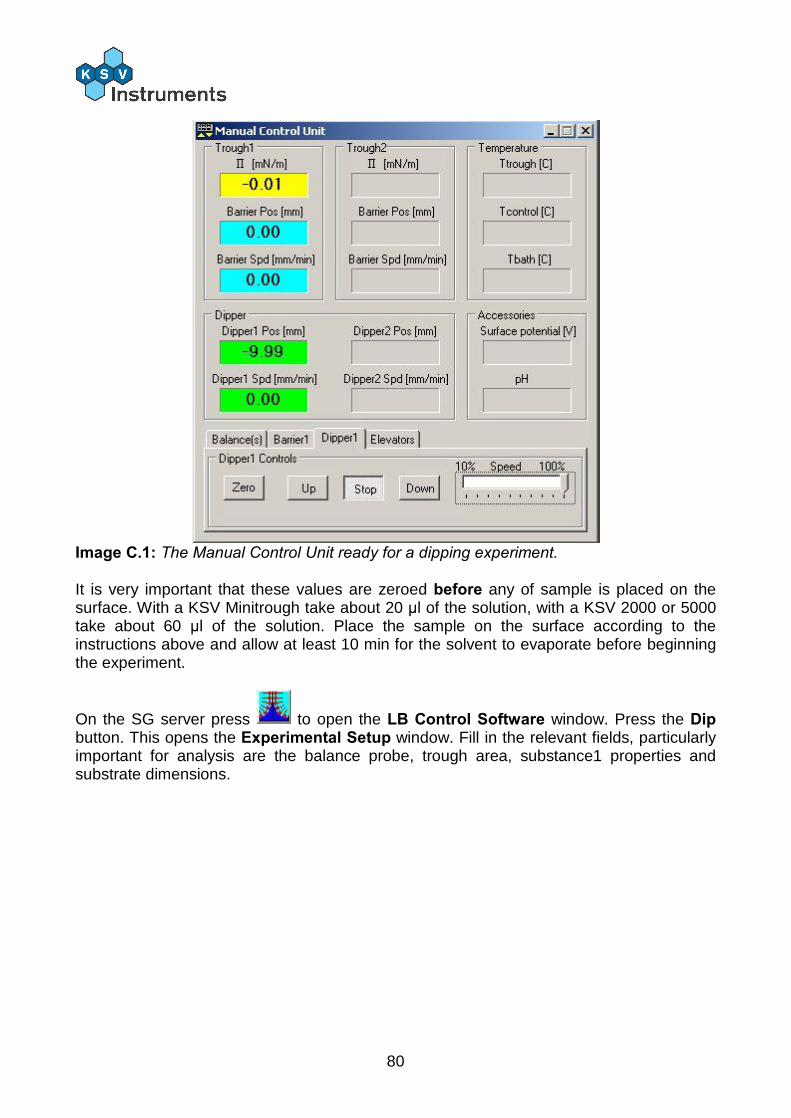
80
Image C.1: The Manual Control Unit ready for a dipping experiment. It is very important that these values are zeroed before any of sample is placed on the surface. With a KSV Minitrough take about 20 µl of the solution, with a KSV 2000 or 5000 take about 60 µl of the solution. Place the sample on the surface according to the instructions above and allow at least 10 min for the solvent to evaporate before beginning the experiment.
On the SG server press to open the LB Control Software window. Press the Dip button. This opens the Experimental Setup window. Fill in the relevant fields, particularly important for analysis are the balance probe, trough area, substance1 properties and substrate dimensions.

81
Image C.2: The Experimental Setup window filled for a dipping experiment. Press Start to continue. In the Trough Controls window select the following options.
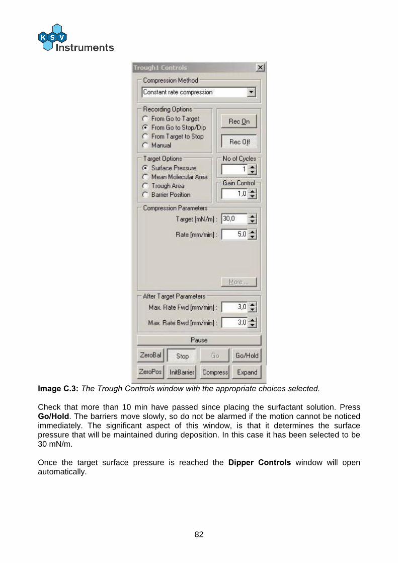
82
Image C.3: The Trough Controls window with the appropriate choices selected. Check that more than 10 min have passed since placing the surfactant solution. Press Go/Hold. The barriers move slowly, so do not be alarmed if the motion cannot be noticed immediately. The significant aspect of this window, is that it determines the surface pressure that will be maintained during deposition. In this case it has been selected to be 30 mN/m. Once the target surface pressure is reached the Dipper Controls window will open automatically.
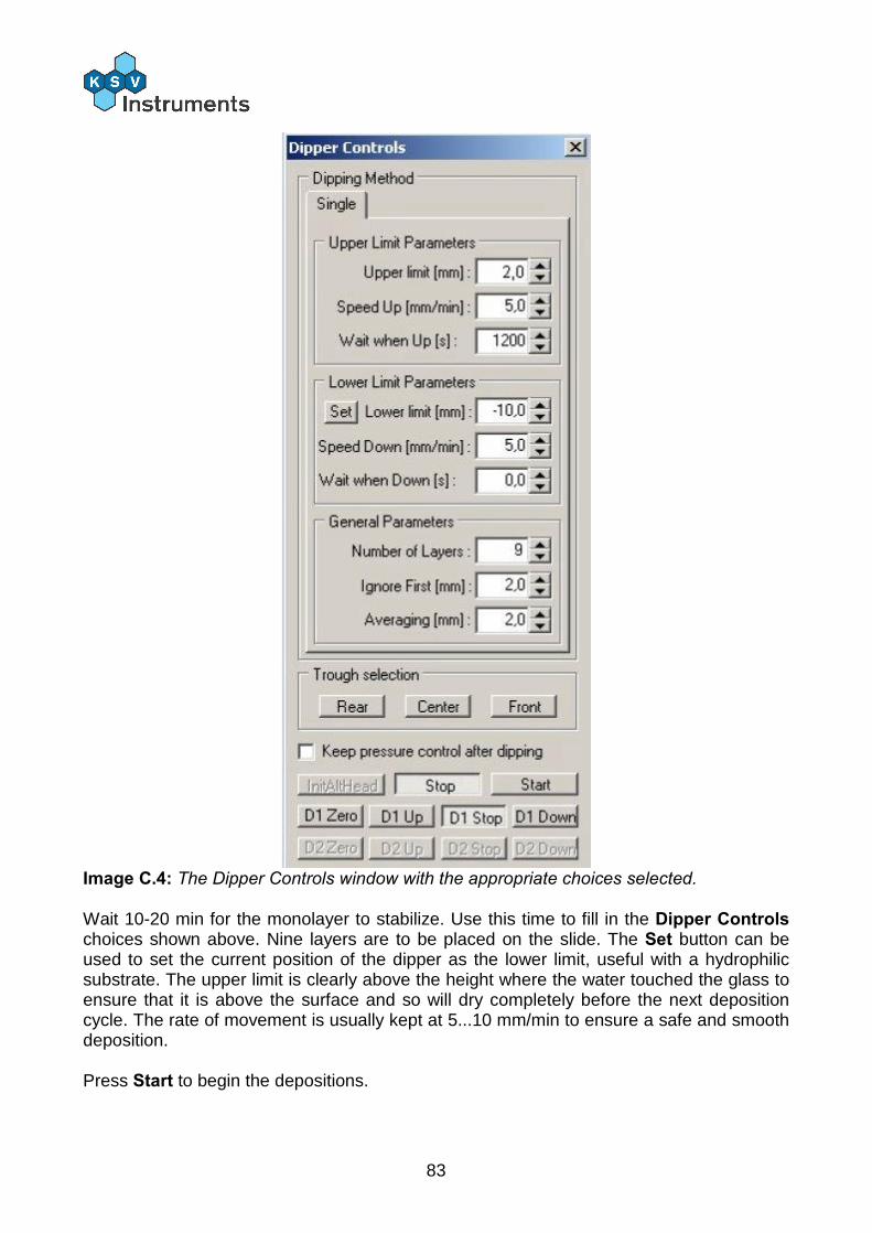
83
Image C.4: The Dipper Controls window with the appropriate choices selected. Wait 10-20 min for the monolayer to stabilize. Use this time to fill in the Dipper Controls choices shown above. Nine layers are to be placed on the slide. The Set button can be used to set the current position of the dipper as the lower limit, useful with a hydrophilic substrate. The upper limit is clearly above the height where the water touched the glass to ensure that it is above the surface and so will dry completely before the next deposition cycle. The rate of movement is usually kept at 5...10 mm/min to ensure a safe and smooth deposition. Press Start to begin the depositions.
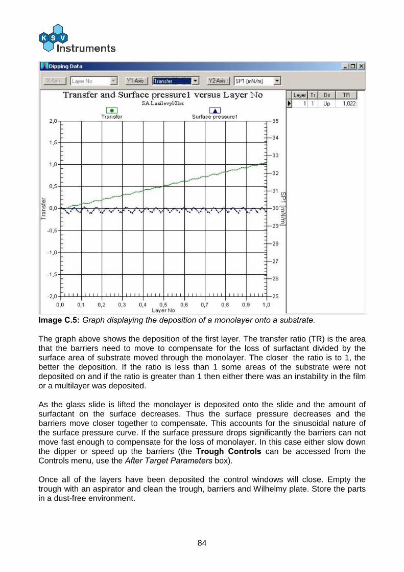
84
Image C.5: Graph displaying the deposition of a monolayer onto a substrate. The graph above shows the deposition of the first layer. The transfer ratio (TR) is the area that the barriers need to move to compensate for the loss of surfactant divided by the surface area of substrate moved through the monolayer. The closer the ratio is to 1, the better the deposition. If the ratio is less than 1 some areas of the substrate were not deposited on and if the ratio is greater than 1 then either there was an instability in the film or a multilayer was deposited. As the glass slide is lifted the monolayer is deposited onto the slide and the amount of surfactant on the surface decreases. Thus the surface pressure decreases and the barriers move closer together to compensate. This accounts for the sinusoidal nature of the surface pressure curve. If the surface pressure drops significantly the barriers can not move fast enough to compensate for the loss of monolayer. In this case either slow down the dipper or speed up the barriers (the Trough Controls can be accessed from the Controls menu, use the After Target Parameters box). Once all of the layers have been deposited the control windows will close. Empty the trough with an aspirator and clean the trough, barriers and Wilhelmy plate. Store the parts in a dust-free environment.
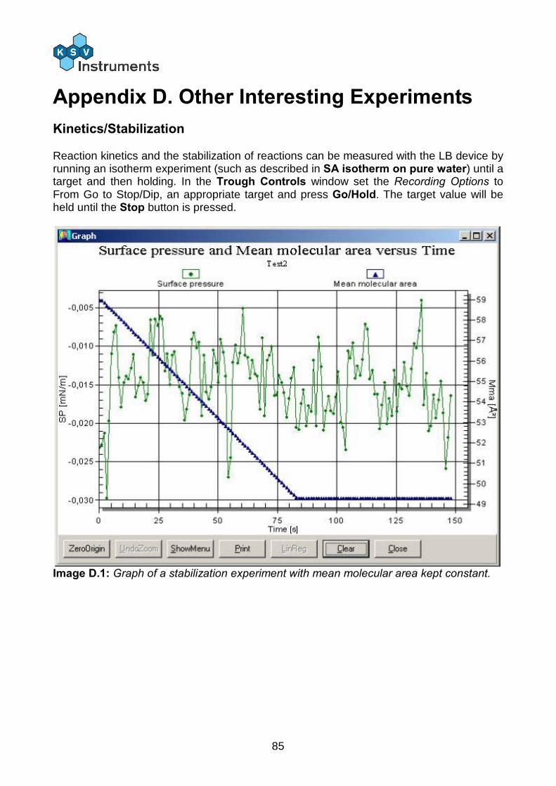
85
Appendix D. Other Interesting Experiments Kinetics/Stabilization
Reaction kinetics and the stabilization of reactions can be measured with the LB device by running an isotherm experiment (such as described in SA isotherm on pure water) until a target and then holding. In the Trough Controls window set the Recording Options to From Go to Stop/Dip, an appropriate target and press Go/Hold. The target value will be held until the Stop button is pressed.
Image D.1: Graph of a stabilization experiment with mean molecular area kept constant.
86
Hysteresis
Hysteresis can be measured with the LB device by running an isotherm experiment (such as described in SA isotherm on pure water) by running several cycles of compressions and expansions. In the Trough Controls window once the No of Cycles is increased above 1 the More... button becomes active. Select the number of cycles to run. Press the More... button to set the Expansion Parameters. With Surface Pressure as the Target Option the Expansion Parameters are return target surface pressure, rate of expansion and how long to wait after compression or expansion. The use of paper Wilhelmy plates during an hysteresis experiment is recommended.
Oscillating Barriers
The visco-elasticity of a monolayer can be investigated with oscillating barriers. Start an isotherm experiment (such as described in SA isotherm on pure water) and select Barrier Oscillation as the Compression Method. The monolayer will be compressed to the target after which the barriers begin to oscillate at the set Frequency and with an amplitude determined by the Area change value. There is a specific analysis program for the data from oscillating barrier measurements, the OscBarrier program.
87
Appendix E. Paper Wilhelmy Plates When to use a paper Wilhelmy plate
Platinum Wilhelmy plates are versatile and useful probes to use in measuring surface pressure. The advantages are accuracy and ease of cleaning and reuse. A disadvantage is that with an experiment involving first compression and then expansion some of the monolayer is deposited onto the plate. This means that the subphase will no longer completely wet the platinum plate and thus the results will be skewed. In such a case a paper Wilhelmy plate will give more accurate and reproducible results. This problem of deposition onto the Wilhelmy plate, however, does not diminish the effectiveness of the platinum plate with single compression experiments.
How to make and use a paper Wilhelmy plate
The paper used to make the Wilhelmy plate should be clean laboratory filter paper. The most important dimension of the plate is the width, as this will be used to calculate the perimeter of the plate. This is important in calculating the surface pressure from the reading of the balance. The paper plates delivered by KSV have a width of 10.3 mm. Care should be taken when cutting all of the sides of the plate to ensure reproducibility. A factor to take into account with when making paper plates is the ease with which it can be made to hang perfectly vertically. Before placing the paper plate on the balance allow the plate to soak the subphase liquid in a separate beaker for at least 30 min. This helps clean the plate by dissolving any contaminants.
Software adjustments required
The software needs to be informed of the change of probe to ensure correct surface pressure readings. Open the LB Control Software from the SG server. Select Database from the Edit menu. Select the Probes tab and add a new field labeled Paper plate. Calculate the perimeter by doubling the width of the paper plate in the relevant field and press the check icon to save the addition. The information is now only aware that several probes exist. To change the current probe select Device Parameters from the Edit menu. In the Balance1 Probe box select Paper plate as the current probe. Change this back to Wilhelmy once finished with paper plate measurements! To upload the changes close the software and restart it. Experiments can now be run, and the paper Wilhelmy plate can be used in just the same manner as the platinum Wilhelmy plate.
Related Documents