Measurements for water Marie-claire ten Veldhuis Measurements in urban drainage

Welcome message from author
This document is posted to help you gain knowledge. Please leave a comment to let me know what you think about it! Share it to your friends and learn new things together.
Transcript
Measurements for
water
Marie-claire ten Veldhuis
Measurements in urban drainage
Challenge the future
DelftUniversity ofTechnology
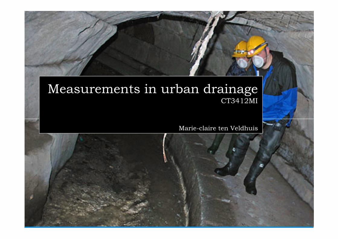
Measurements in urban drainageCT3412MI
Marie-claire ten Veldhuis
2
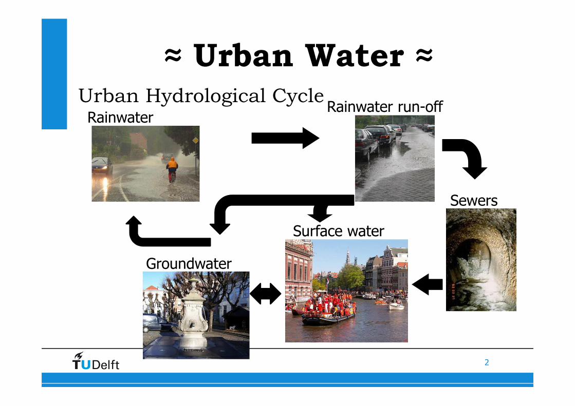
Urban Hydrological CycleRainwater run-off
Sewers
Rainwater
≈ Urban Water ≈
Surface water
Groundwater
3
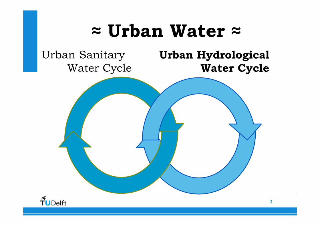
Urban Sanitary
Water Cycle
≈ Urban Water ≈
Urban Hydrological
Water Cycle
4
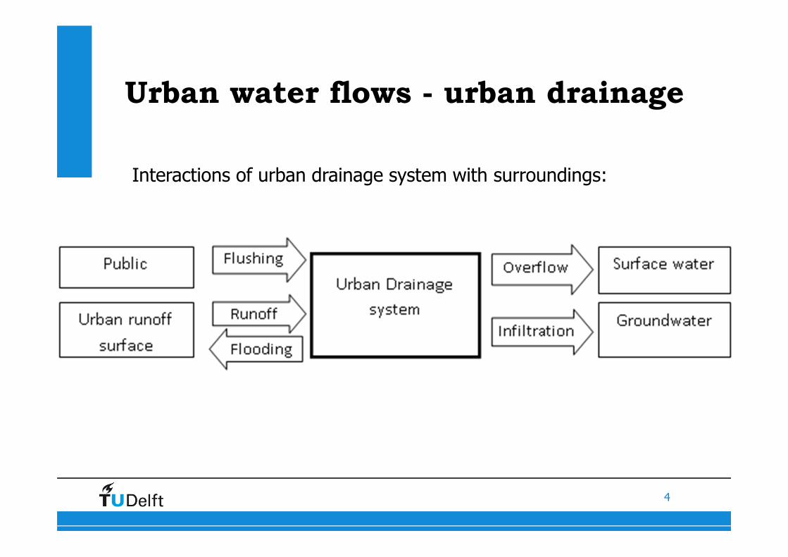
Urban water flows - urban drainage
Interactions of urban drainage system with surroundings:
5
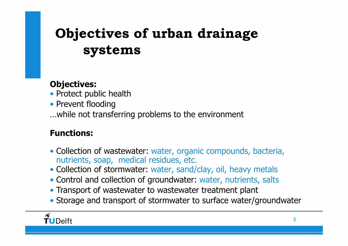
Objectives of urban drainage
systems
Objectives:• Protect public health
• Prevent flooding
…while not transferring problems to the environment
Functions:
• Collection of wastewater: water, organic compounds, bacteria, nutrients, soap, medical residues, etc.
• Collection of stormwater: water, sand/clay, oil, heavy metals
• Control and collection of groundwater: water, nutrients, salts
• Transport of wastewater to wastewater treatment plant
• Storage and transport of stormwater to surface water/groundwater
6
Measurements in urban drainage
What parameters to measure and where ?
7
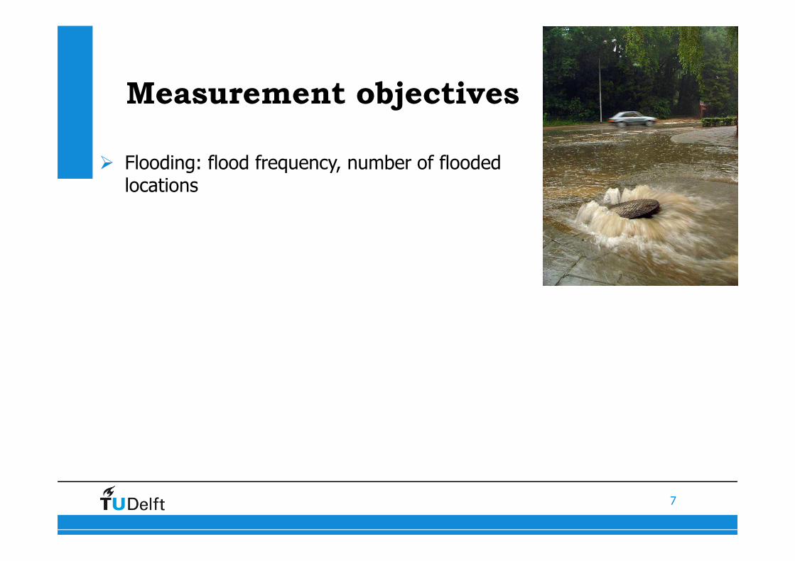
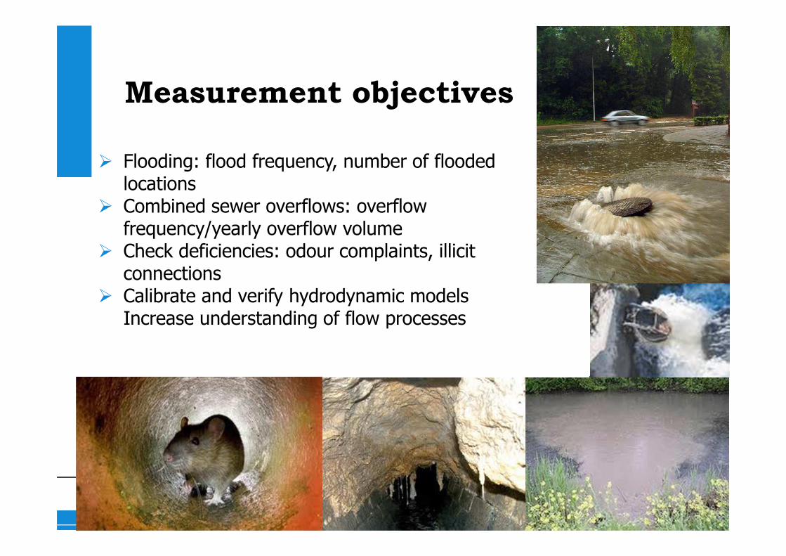
Measurement objectives
� Flooding: flood frequency, number of flooded locations
8
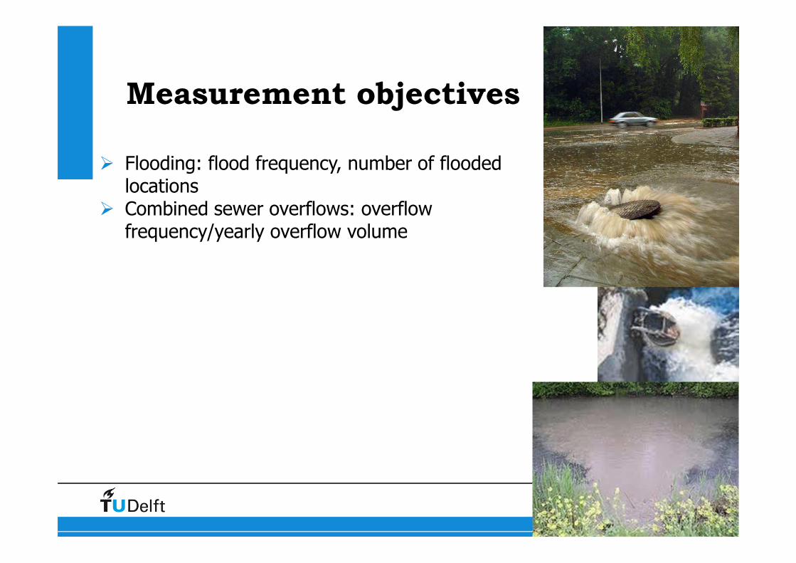
Measurement objectives
� Flooding: flood frequency, number of flooded locations
� Combined sewer overflows: overflow frequency/yearly overflow volume
9
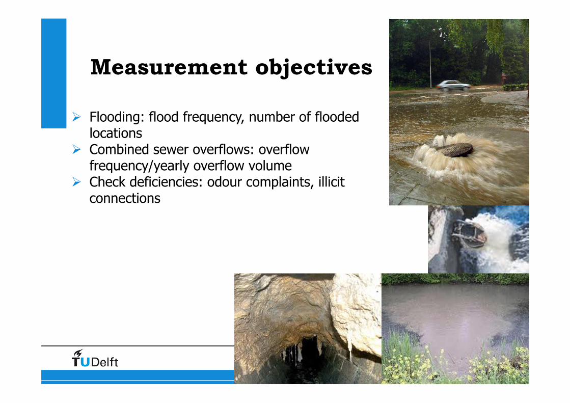
Measurement objectives
� Flooding: flood frequency, number of flooded locations
� Combined sewer overflows: overflow frequency/yearly overflow volume
� Check deficiencies: odour complaints, illicit connections
10
Measurement objectives
� Flooding: flood frequency, number of flooded locations
� Combined sewer overflows: overflow frequency/yearly overflow volume
� Check deficiencies: odour complaints, illicit connections
� Calibrate and verify hydrodynamic models Increase understanding of flow processes

11
Measurement objectives
� Flooding: flood frequency, number of flooded locations
� Combined sewer overflows: overflow frequency/yearly overflow volume
� Check deficiencies: odour complaints, illicit connections
� Calibrate and verify hydrodynamic models� Increase understanding of flow processes� Real-time control and operation

12
Measurement parameters
� Water levels: quantify overflow frequencies, flooding frequencies, overflow volumes at weirs, calibrate hydrodynamic models
� Discharge: quantify overflow volumes, calibrate models
� Rainfall
� Water quality parameters, some examples:� Temperature: to identify illicit connections� Turbidity: erosion and sedimentation processes,
relations with other pollutants� Oxygen content: odour complaints, effects of
organic pollution loads
� And many more…

13
Measurement plan
Combined sewer overflows: � overflow frequency� overflow volume � rainfall
� Measurement parameters?
� Measurement locations?
14
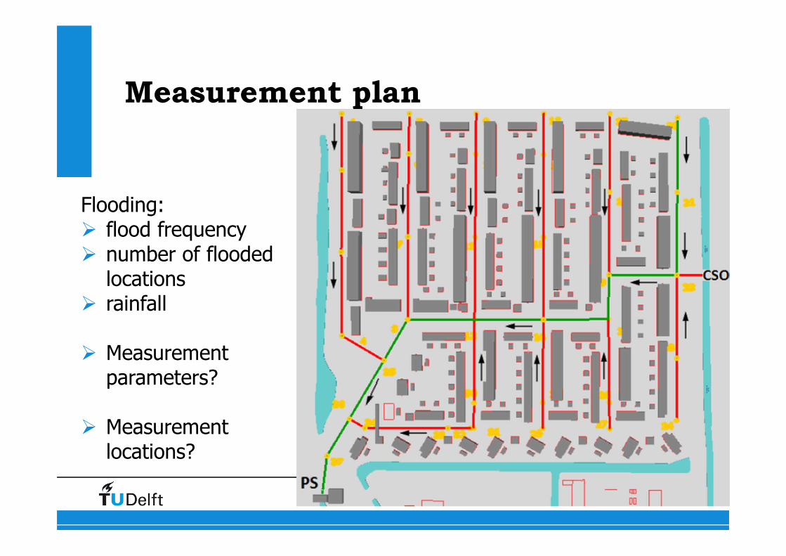
Measurement plan
Flooding:� flood frequency� number of flooded
locations� rainfall
� Measurement parameters?
� Measurement locations?
15
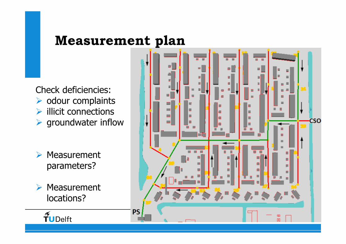
Measurement plan
Check deficiencies:� odour complaints � illicit connections� groundwater inflow
� Measurement parameters?
� Measurement locations?
16
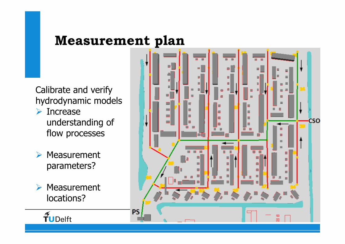
Measurement plan
Calibrate and verify hydrodynamic models� Increase
understanding of flow processes
� Measurement parameters?
� Measurement locations?
17
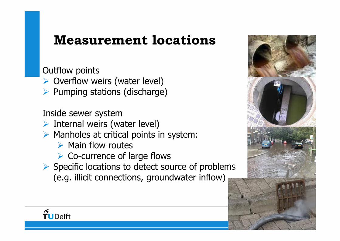
Measurement locations
Outflow points� Overflow weirs (water level)� Pumping stations (discharge)
Inside sewer system� Internal weirs (water level)� Manholes at critical points in system:
� Main flow routes� Co-currence of large flows
� Specific locations to detect source of problems(e.g. illicit connections, groundwater inflow)
18
Measurement parameters:
Rainfall
Urban areas:
Fast runoff processes→ Need for fine-scale rainfall data→ High resolution in time and space
Processes at 5 – 10 minutes time-scale→ Data at 1 - 5 minutes time-scaleProcesses at 100 – 1000 m time scale→ Data at 50 – 500 m spatial scale

19
Measurement parameters:
Urban rainfall
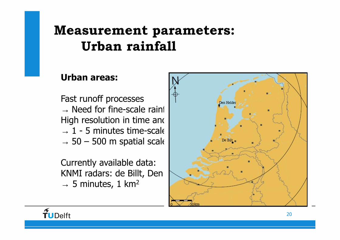
Urban areas:
Fast runoff processes→ Need for fine-scale rainfall dataHigh resolution in time and space:→ 1 - 5 minutes time-scale→ 50 – 500 m spatial scale
Currently available data:KNMI radars: de Billt, Den Helder→ 5 minutes, 1 km2
20
Measurement parameters:
Urban rainfall
Urban areas:
Fast runoff processes→ Need for fine-scale rainfall dataHigh resolution in time and space:→ 1 - 5 minutes time-scale→ 50 – 500 m spatial scale
Currently available data:KNMI radars: de Billt, Den Helder→ 5 minutes, 1 km2
21
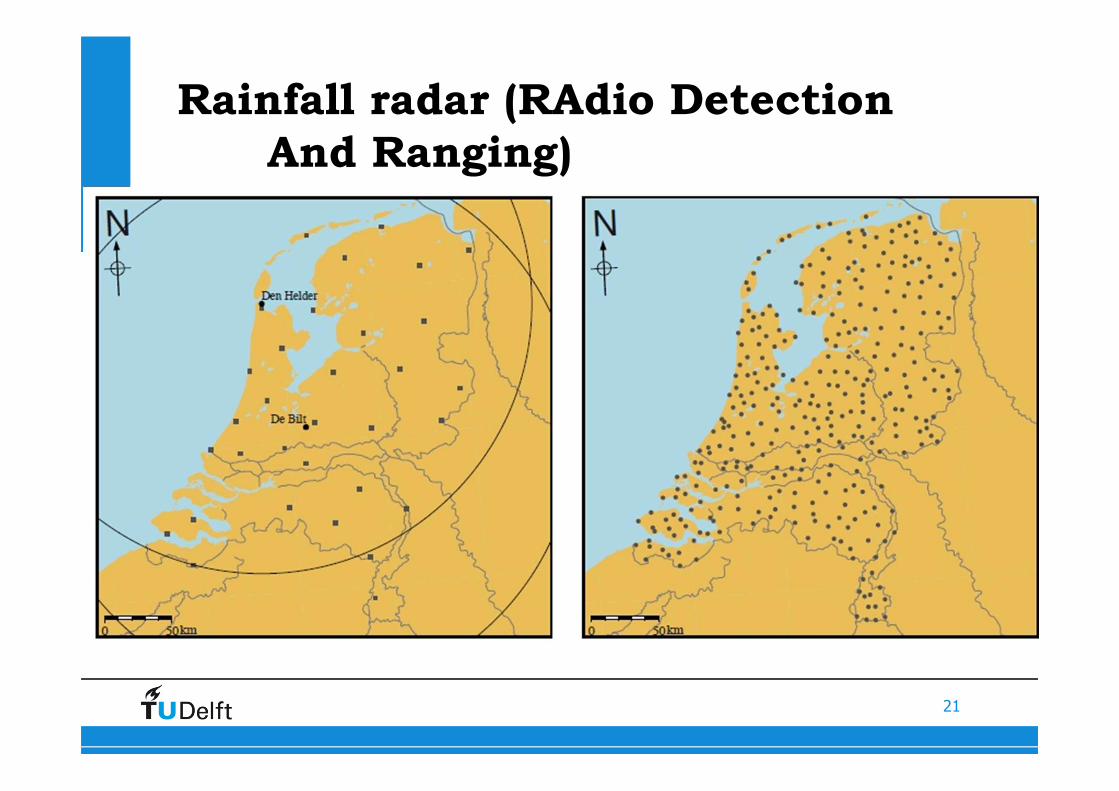
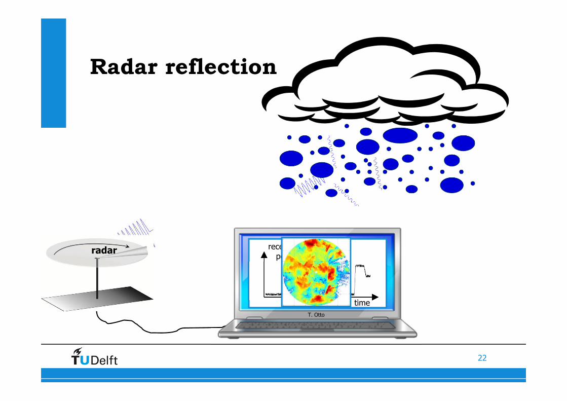
Rainfall radar (RAdio Detection
And Ranging)
Urban areas:
Fast runoff processes→ Need for fine-scale rainfall dataHigh resolution in time and space:→ 1 - 5 minutes time-scale→ 50 – 500 m spatial scale
Currently available data:KNMI radars: de Billt, Den Helder→ 5 minutes, 1 km2
22
PARSAX on top of EWI faculty
T. Otto
receivedpower
time
radar
Radar reflection
23
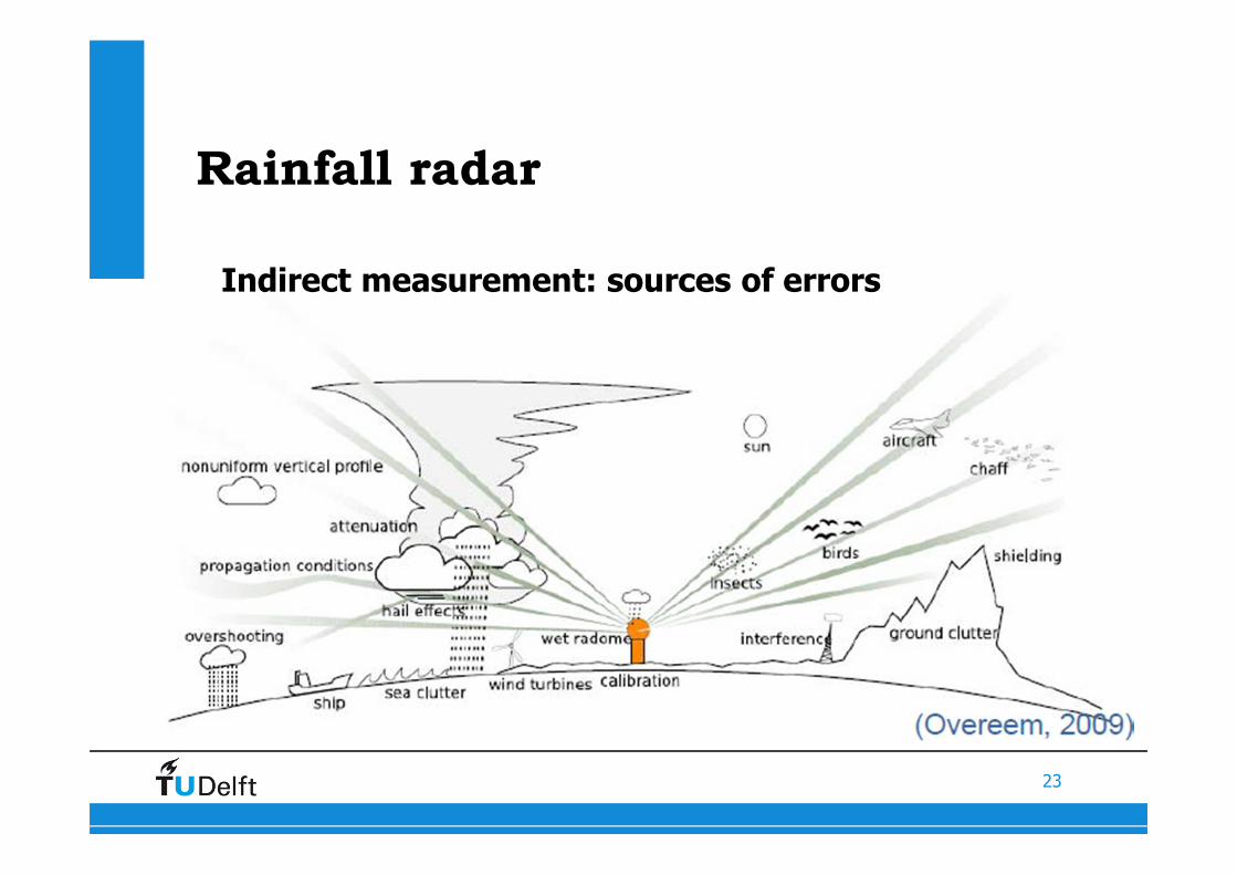
Rainfall radar
Indirect measurement: sources of errors
24
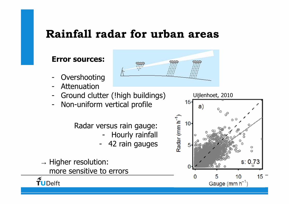
Rainfall radar for urban areas
Error sources:
- Overshooting- Attenuation- Ground clutter (!high buildings)- Non-uniform vertical profile
Radar versus rain gauge:- Hourly rainfall
- 42 rain gauges
→ Higher resolution: more sensitive to errors
Uijlenhoet, 2010
25
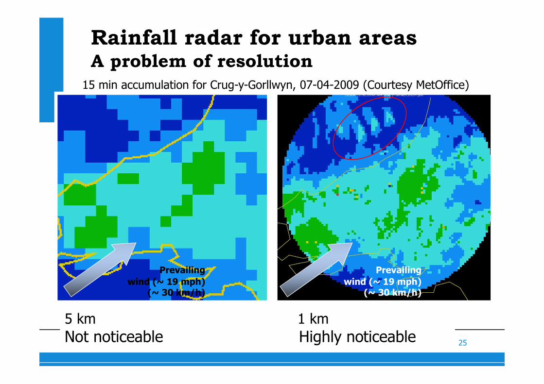
5 km 1 km
Not noticeable Highly noticeable
15 min accumulation for Crug-y-Gorllwyn, 07-04-2009 (Courtesy MetOffice)
Prevailing
wind (~ 19 mph) (~ 30 km/h)
Prevailing
wind (~ 19 mph) (~ 30 km/h)
Rainfall radar for urban areasA problem of resolution
26
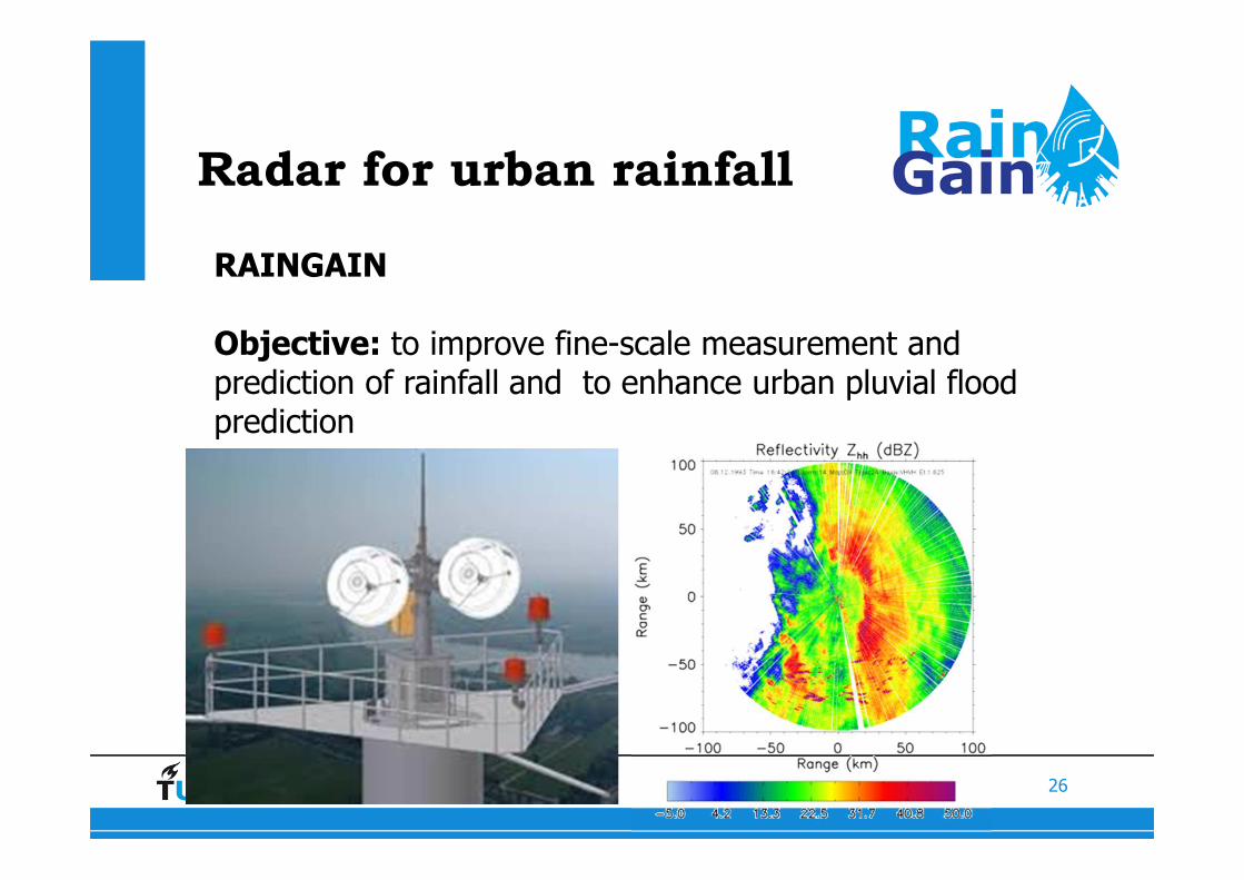
Radar for urban rainfall
RAINGAIN
Objective: to improve fine-scale measurement and prediction of rainfall and to enhance urban pluvial flood prediction
27
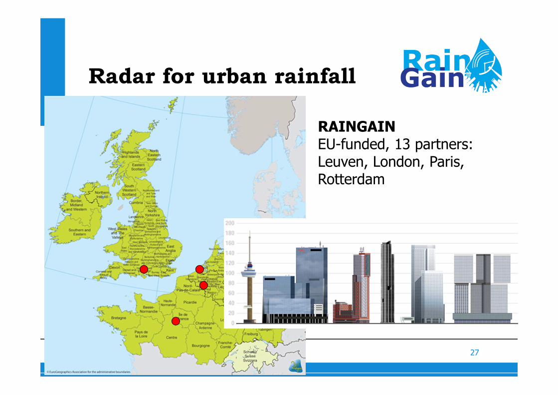
Radar for urban rainfall
RAINGAIN EU-funded, 13 partners: Leuven, London, Paris, Rotterdam
28

29
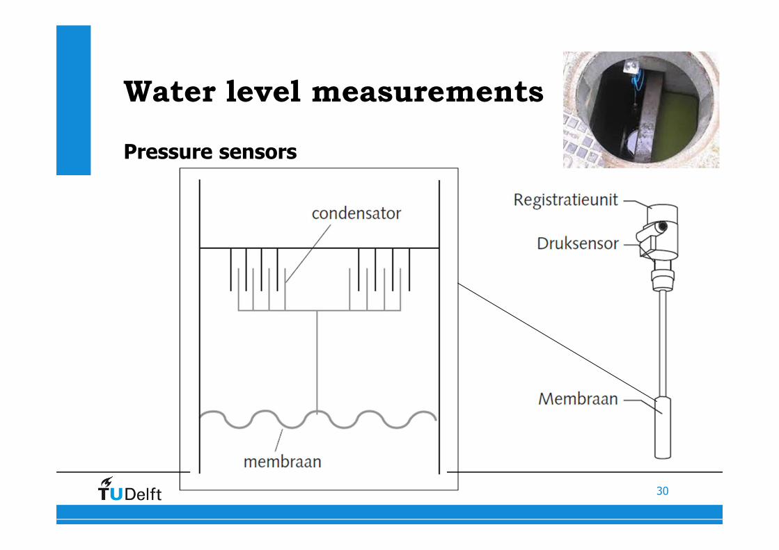
Water level measurements
Pressure sensors
30
Water level measurements
Pressure sensors
31
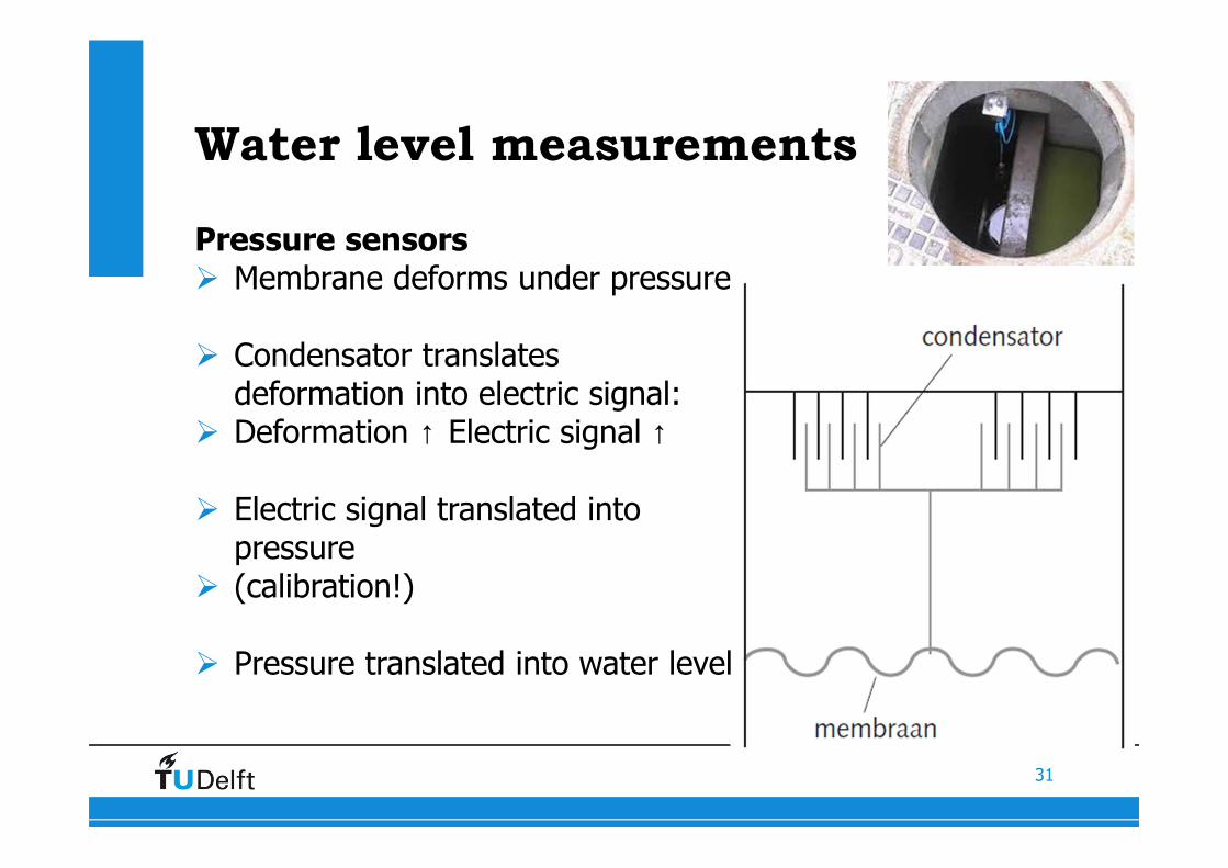
Water level measurements
Pressure sensors� Membrane deforms under pressure
� Condensator translates deformation into electric signal:
� Deformation ↑ Electric signal ↑
� Electric signal translated into pressure
� (calibration!)
� Pressure translated into water level
32
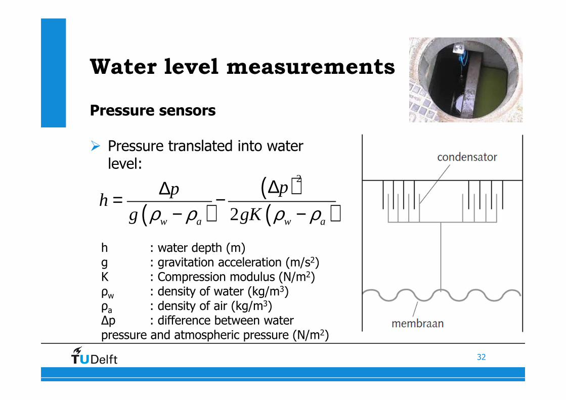
Water level measurements
Pressure sensors
� Pressure translated into water level:
( )( )( )
2
2w a w a
pph
g gKρ ρ ρ ρ∆∆= −
− −
h : water depth (m)g : gravitation acceleration (m/s2)K : Compression modulus (N/m2)ρw : density of water (kg/m3)ρa : density of air (kg/m3)∆p : difference between water pressure and atmospheric pressure (N/m2)
33
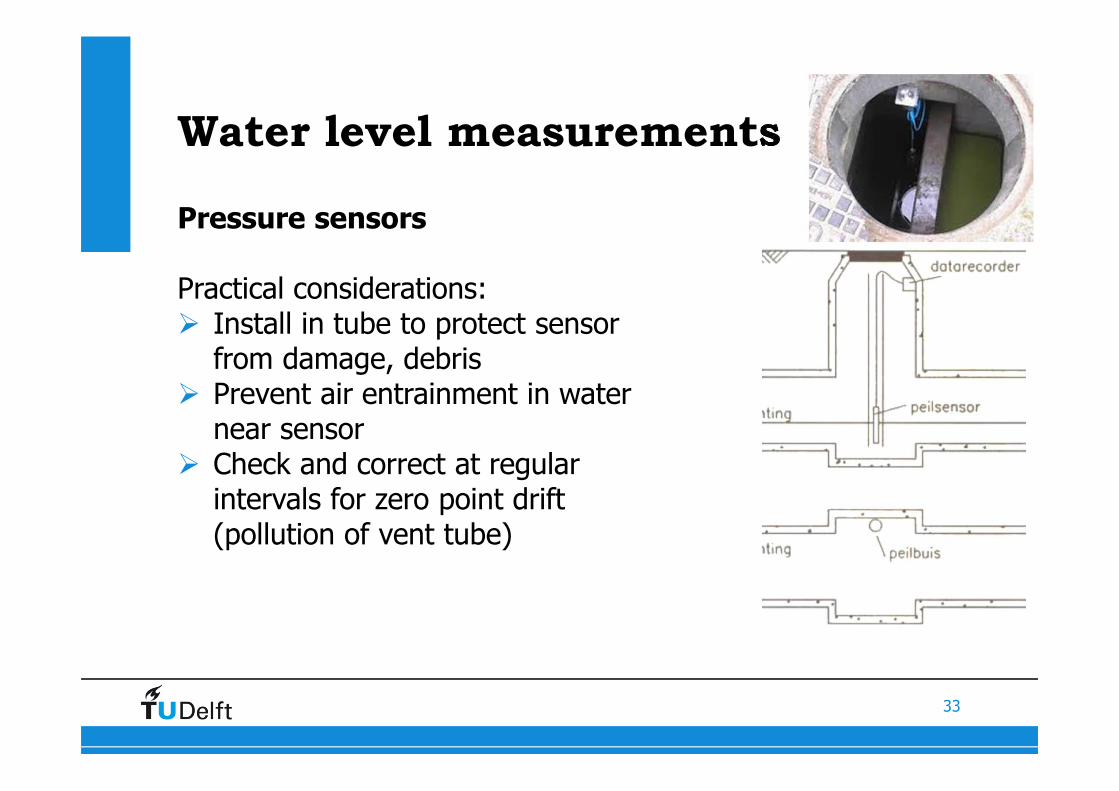
Water level measurements
Pressure sensors
Practical considerations:� Install in tube to protect sensor
from damage, debris� Prevent air entrainment in water
near sensor� Check and correct at regular
intervals for zero point drift(pollution of vent tube)
34
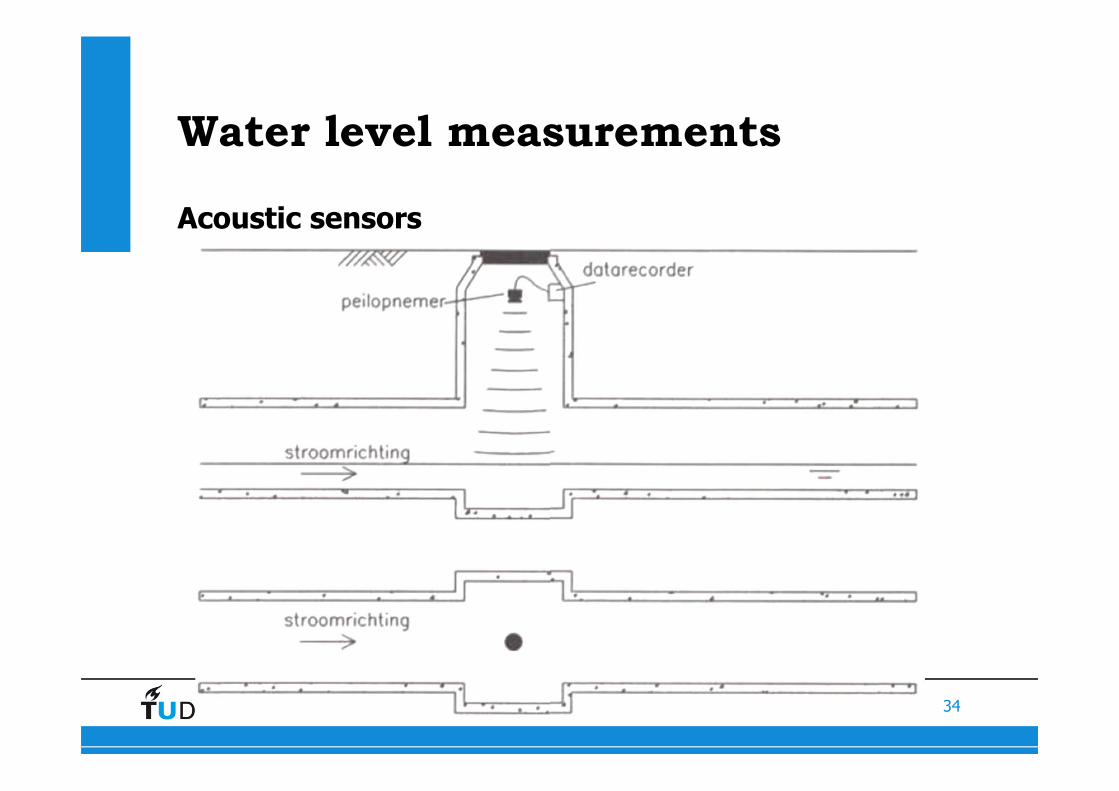
Water level measurements
Acoustic sensors
35
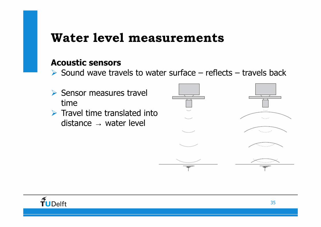
Water level measurements
Acoustic sensors� Sound wave travels to water surface – reflects – travels back
� Sensor measures travel time
� Travel time translated intodistance → water level
36
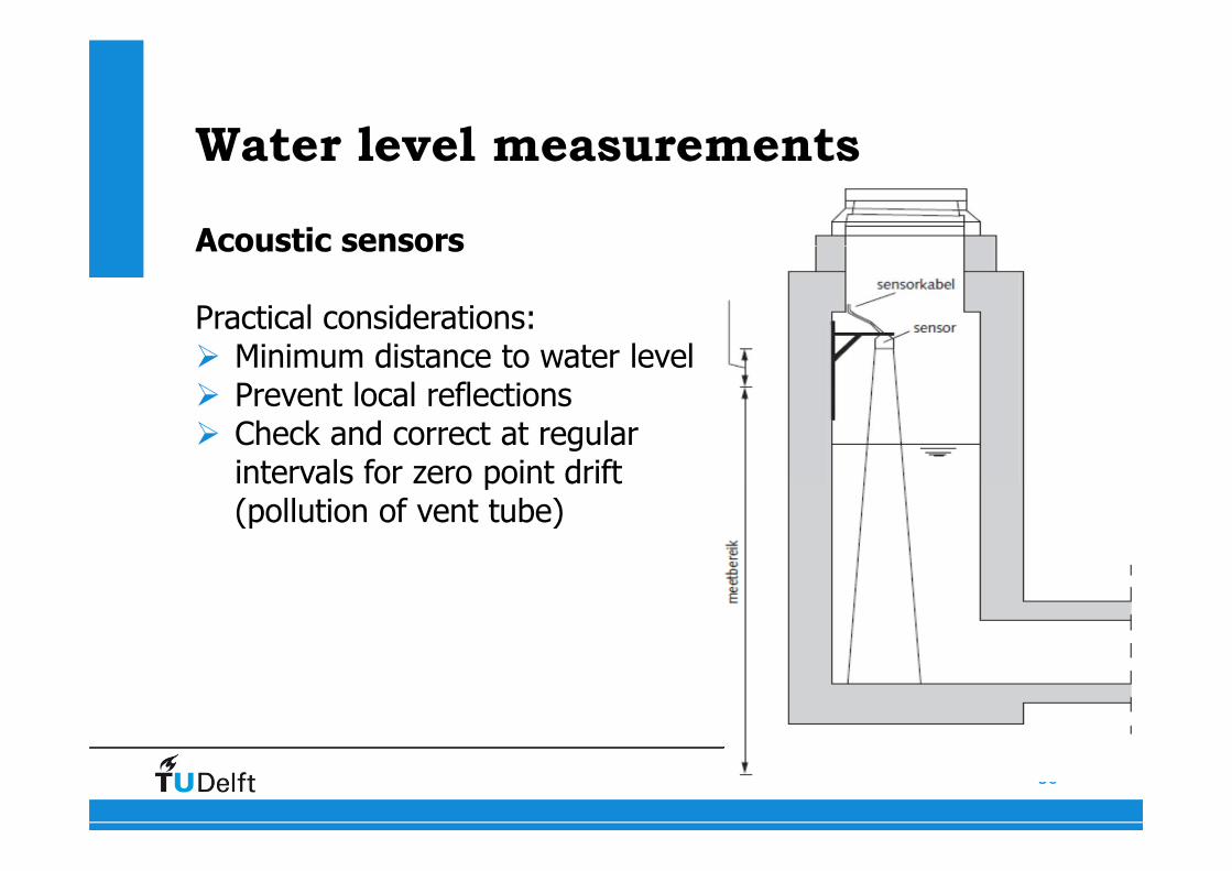
Water level measurements
Acoustic sensors
Practical considerations:� Minimum distance to water level� Prevent local reflections� Check and correct at regular
intervals for zero point drift(pollution of vent tube)
37
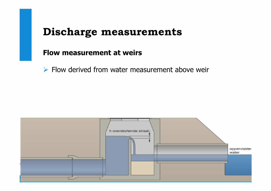
Discharge measurements
Flow measurement at weirs
� Flow derived from water measurement above weir
38
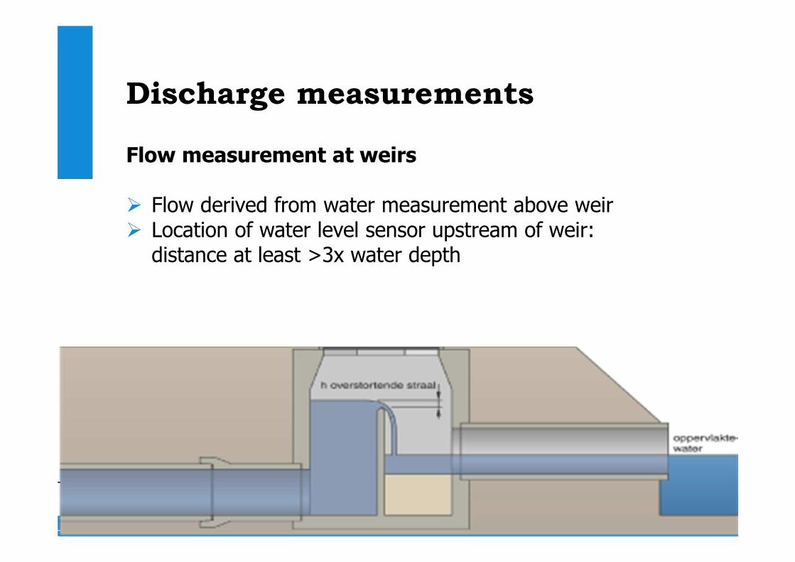
Discharge measurements
Flow measurement at weirs
� Flow derived from water measurement above weir� Location of water level sensor upstream of weir:
distance at least >3x water depth
39
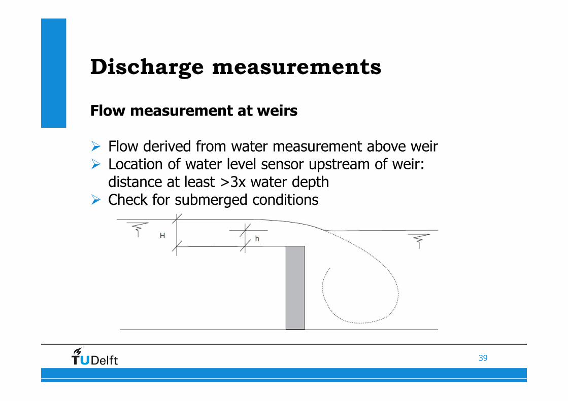
Discharge measurements
Flow measurement at weirs
� Flow derived from water measurement above weir� Location of water level sensor upstream of weir:
distance at least >3x water depth� Check for submerged conditions
40
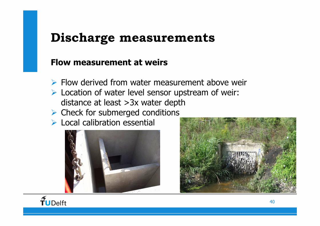
Discharge measurements
Flow measurement at weirs
� Flow derived from water measurement above weir� Location of water level sensor upstream of weir:
distance at least >3x water depth� Check for submerged conditions� Local calibration essential
41
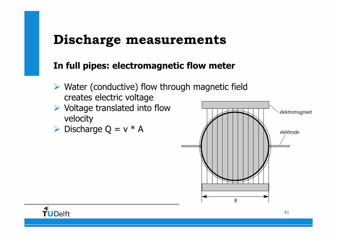
Discharge measurements
In full pipes: electromagnetic flow meter
� Water (conductive) flow through magnetic field creates electric voltage
� Voltage translated into flowvelocity
� Discharge Q = v * A

42
Discharge measurements
In full pipes: electromagnetic flow meter
Applications:� Outgoing main of pumps in pumping station� Influent wastewater treatment plant� Industrial discharge pipe� Siphons in sewer system
http://youtu.be/f949gpKdCI4

43
44
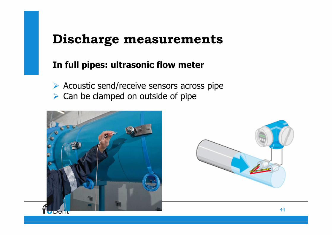
Discharge measurements
In full pipes: ultrasonic flow meter
� Acoustic send/receive sensors across pipe� Can be clamped on outside of pipe

45
46
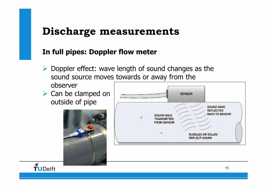
Discharge measurements
In full pipes: Doppler flow meter
� Doppler effect: wave length of sound changes as the sound source moves towards or away from the observer
� Can be clamped onoutside of pipe

47
48
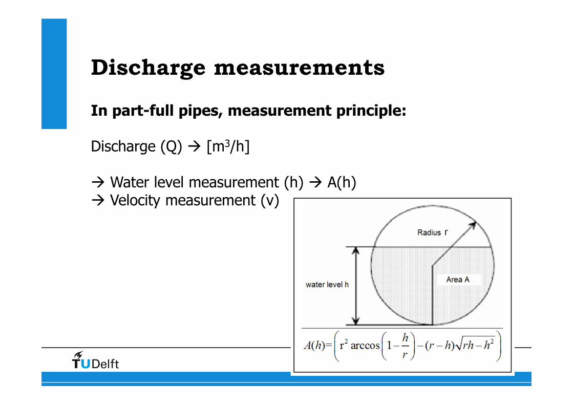
Discharge measurements
In part-full pipes, measurement principle:
Discharge (Q) � [m3/h]
� Water level measurement (h) � A(h)� Velocity measurement (v)
49
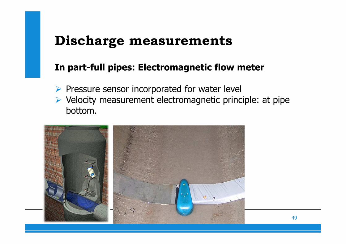
Discharge measurements
In part-full pipes: Electromagnetic flow meter
� Pressure sensor incorporated for water level� Velocity measurement electromagnetic principle: at pipe
bottom.
50
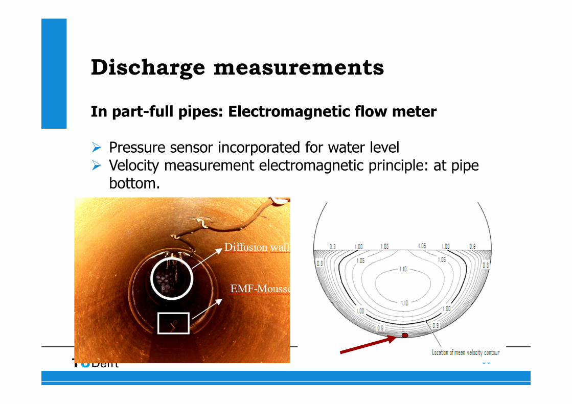
Discharge measurements
In part-full pipes: Electromagnetic flow meter
� Pressure sensor incorporated for water level� Velocity measurement electromagnetic principle: at pipe
bottom.
51
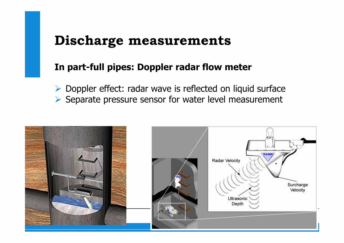
Discharge measurements
In part-full pipes: Doppler radar flow meter
� Doppler effect: radar wave is reflected on liquid surface� Separate pressure sensor for water level measurement
52
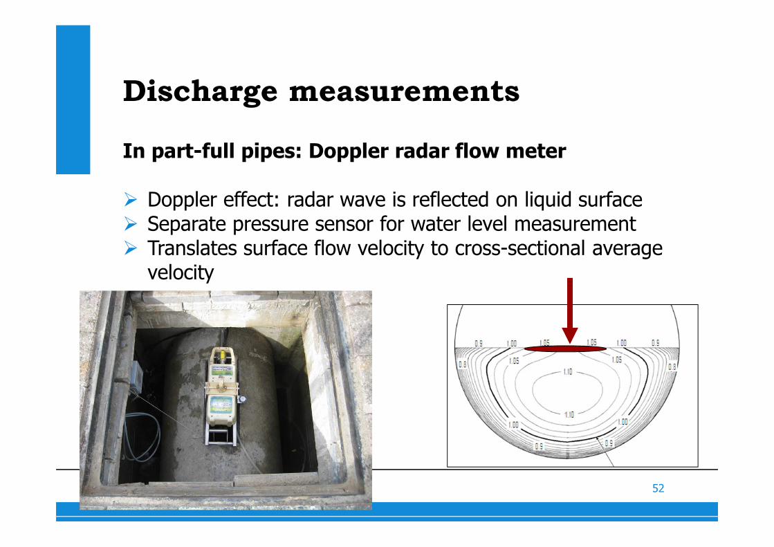
Discharge measurements
In part-full pipes: Doppler radar flow meter
� Doppler effect: radar wave is reflected on liquid surface� Separate pressure sensor for water level measurement� Translates surface flow velocity to cross-sectional average
velocity
53
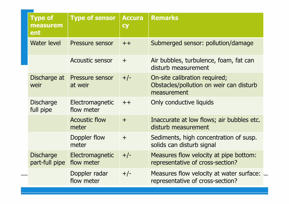
Type of measurement
Type of sensor Accuracy
Remarks
Water level Pressure sensor ++ Submerged sensor: pollution/damage
Acoustic sensor + Air bubbles, turbulence, foam, fat can disturb measurement
Discharge at weir
Pressure sensor at weir
+/- On-site calibration required;Obstacles/pollution on weir can disturb measurement
Dischargefull pipe
Electromagneticflow meter
++ Only conductive liquids
Acoustic flow meter
+ Inaccurate at low flows; air bubbles etc. disturb measurement
Doppler flow meter
+ Sediments, high concentration of susp. solids can disturb signal
Dischargepart-full pipe
Electromagneticflow meter
+/- Measures flow velocity at pipe bottom: representative of cross-section?
Doppler radar flow meter
+/- Measures flow velocity at water surface: representative of cross-section?
54
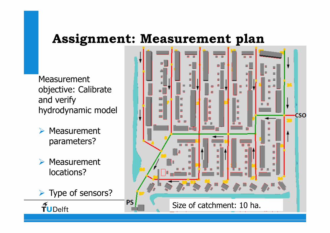
Assignment: Measurement plan
Measurement objective: Calibrate and verify hydrodynamic model
� Measurement parameters?
� Measurement locations?
� Type of sensors?
Size of catchment: 10 ha.
55
Assignment: Measurement plan
Measurement objective: Calibrate and verify hydrodynamic model
Measurement parameters:�
56
Assignment: Measurement plan
Measurement objective: Calibrate and verify hydrodynamic model
Measurement parameters:� Rainfall: � Flow: � Water levels:
57
Assignment: Measurement plan
Measurement objective: Calibrate and verify hydrodynamic model
Measurement parameters and locations:� Rainfall: � Flow: � Water levels:
58
Assignment: Measurement plan
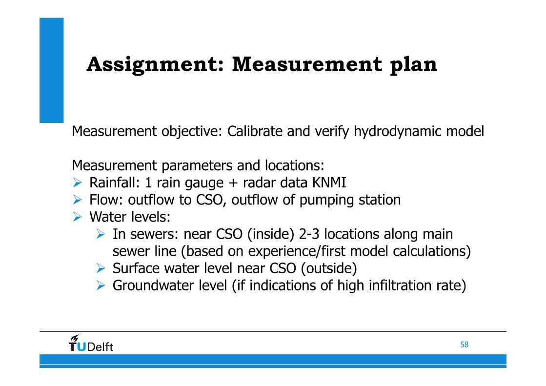
Measurement objective: Calibrate and verify hydrodynamic model
Measurement parameters and locations:� Rainfall: 1 rain gauge + radar data KNMI� Flow: outflow to CSO, outflow of pumping station� Water levels:
� In sewers: near CSO (inside) 2-3 locations along main sewer line (based on experience/first model calculations)
� Surface water level near CSO (outside)� Groundwater level (if indications of high infiltration rate)
59
Assignment: Measurement plan
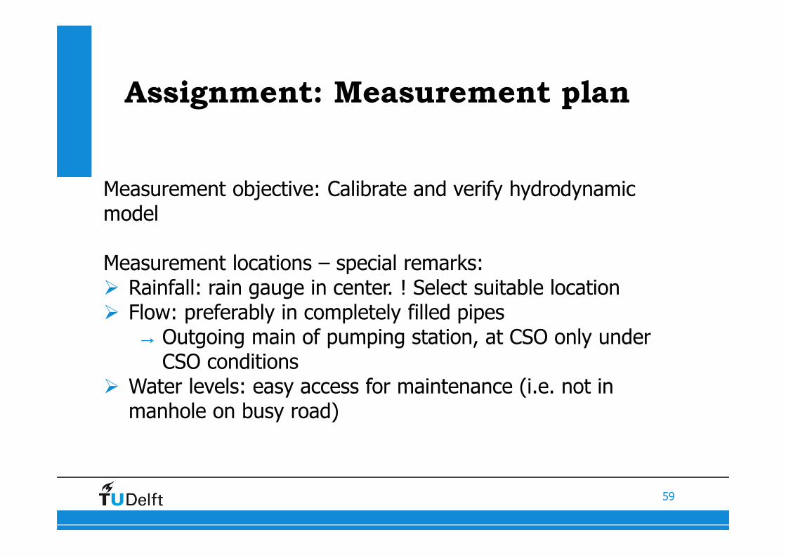
Measurement objective: Calibrate and verify hydrodynamic model
Measurement locations – special remarks:� Rainfall: rain gauge in center. ! Select suitable location� Flow: preferably in completely filled pipes
→ Outgoing main of pumping station, at CSO only under CSO conditions
� Water levels: easy access for maintenance (i.e. not in manhole on busy road)
60
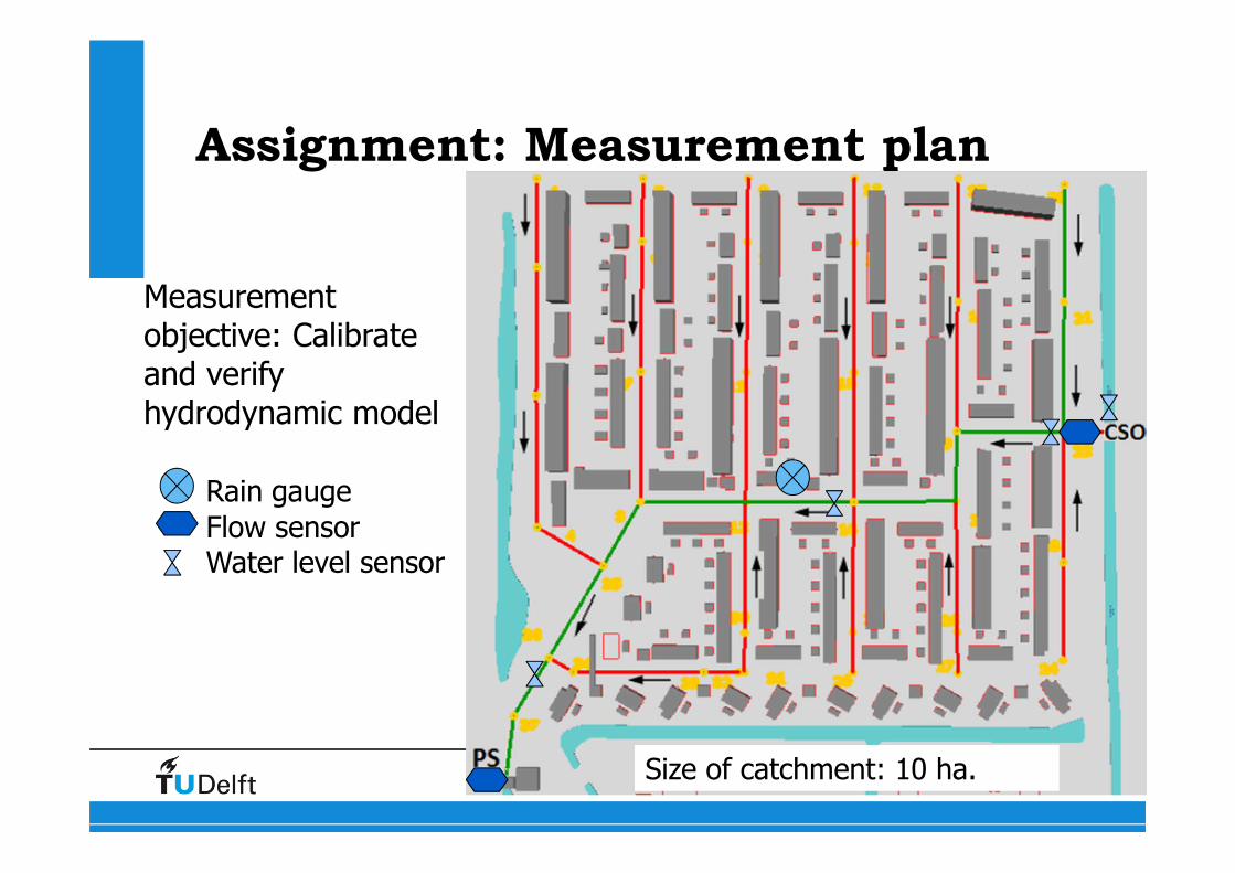
Assignment: Measurement plan
Measurement objective: Calibrate and verify hydrodynamic model
Rain gauge
Flow sensorWater level sensor
Size of catchment: 10 ha.
Related Documents