1 Budapest University of Technology and Economics Department of Measurement and Information Systems Measurement laboratory 3 Embedded operating systems Student’s guide Version: 1.7 2015 / September / 10 NASZÁLY Gábor [email protected]

Welcome message from author
This document is posted to help you gain knowledge. Please leave a comment to let me know what you think about it! Share it to your friends and learn new things together.
Transcript
1
Budapest University of Technology and Economics
Department of Measurement and Information Systems
Measurement laboratory 3
Embedded operating systems
Student’s guide
Version: 1.7
2015 / September / 10
NASZÁLY Gábor

2
Table of contents
1. Introduction ........................................................................................................................ 3 2. Theoretical overview .......................................................................................................... 4
2.1. Programming microcontrollers in C language ............................................................. 5 2.1.1. Accessing I/O registers ......................................................................................... 5 2.1.2. Interrupts .............................................................................................................. 6 2.1.3. Using standard I/O ............................................................................................... 7
2.2. Embedded operating systems ...................................................................................... 9
2.2.1. The embedded OS as software architecture ......................................................... 9 2.2.2. Task states .......................................................................................................... 10 2.2.3. Task structures .................................................................................................... 11 2.2.4. Context switching ............................................................................................... 11
2.2.5. Time management .............................................................................................. 11 2.2.6. Shared resources ................................................................................................. 12 2.2.7. Interrupts [optional] ............................................................................................ 13 2.2.8. Desktop OS vs. embedded OS ........................................................................... 16
2.3. Introducing μC/OS..................................................................................................... 17 2.3.1. The story [reading] ............................................................................................. 17 2.3.2. The structure of μC/OS ...................................................................................... 17
2.3.3. The scheduler ..................................................................................................... 18 2.3.4. The structure of a μC/OS application ................................................................. 20 2.3.5. Creating and deleting tasks ................................................................................ 20
2.3.6. Time management .............................................................................................. 21 2.3.7. Semaphores ........................................................................................................ 21
2.3.8. Interrupts [optional] ............................................................................................ 21
3. Exercises ........................................................................................................................... 23
1. Accessing the I/O registers of the microcontroller ........................................................... 23 2. Interrupts .......................................................................................................................... 24
3. Stdio operations ................................................................................................................ 24 4a. μC/OS – a single task ..................................................................................................... 24 4b. μC/OS – time management ............................................................................................ 24 4c. μC/OS – semaphores (guarding shared resources) ......................................................... 24
4d. μC/OS – interrupts (and semaphores for event signaling) [optional] ............................ 25 4. Reference .......................................................................................................................... 26
4.1. μC/OS functions ........................................................................................................ 26 4.1.1. Task management ............................................................................................... 26 4.1.2. Time management .............................................................................................. 27
4.1.3. Semaphores ........................................................................................................ 28
4.2. Description of the APIs made for the board .............................................................. 30
4.2.1. LCD management .............................................................................................. 30 4.2.2. Handling the serial port ...................................................................................... 31 4.2.3. Using the A/D converter .................................................................................... 32
4.3. Interrupts and vector names belonging to them ......................................................... 34 5. Test questions ................................................................................................................... 35
6. Recommended / used bibliography .................................................................................. 37 7. Change log ........................................................................................................................ 38
3
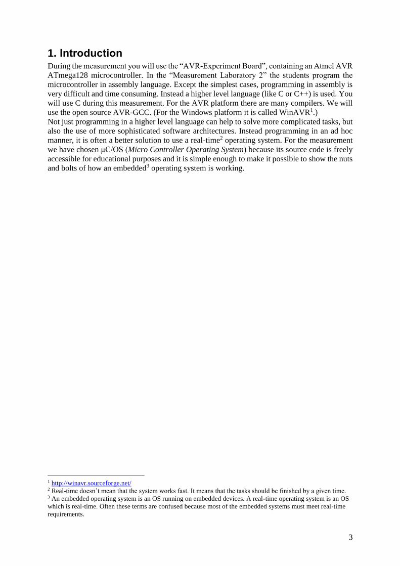
1. Introduction During the measurement you will use the “AVR-Experiment Board”, containing an Atmel AVR
ATmega128 microcontroller. In the “Measurement Laboratory 2” the students program the
microcontroller in assembly language. Except the simplest cases, programming in assembly is
very difficult and time consuming. Instead a higher level language (like C or C++) is used. You
will use C during this measurement. For the AVR platform there are many compilers. We will
use the open source AVR-GCC. (For the Windows platform it is called WinAVR1.)
Not just programming in a higher level language can help to solve more complicated tasks, but
also the use of more sophisticated software architectures. Instead programming in an ad hoc
manner, it is often a better solution to use a real-time2 operating system. For the measurement
we have chosen μC/OS (Micro Controller Operating System) because its source code is freely
accessible for educational purposes and it is simple enough to make it possible to show the nuts
and bolts of how an embedded3 operating system is working.
1 http://winavr.sourceforge.net/ 2 Real-time doesn’t mean that the system works fast. It means that the tasks should be finished by a given time. 3 An embedded operating system is an OS running on embedded devices. A real-time operating system is an OS
which is real-time. Often these terms are confused because most of the embedded systems must meet real-time
requirements.
4
2. Theoretical overview
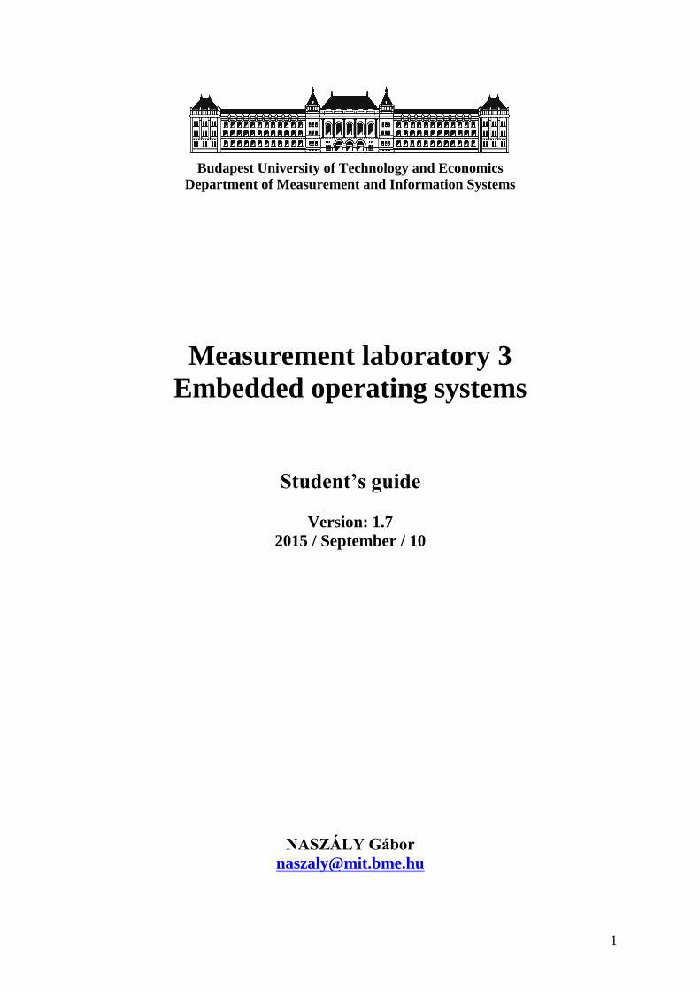
Figure 1: tool-chain during development
During the software development we use a complete tool-chain. This means that the output of
a tool is the input of the next one.
In an ordinary case coding, compiling, linking, running and debugging happen on the same
device. In the case of embedded systems coding, compiling and linking is done on an ordinary
computer (because the embedded systems generally lack the presence of a big display, console,
and the capability to run a development environment on them). A further difference is that after
linking we have to figure out where to place the linked code in the device’s program and data
memory (this is called locating). And finally we eventually need to download the code to the
target.
A compiler that runs on platform “A” and compiles code for platform “B” is called cross-
compiler. AVR-GCC is one of these software tools. One interesting thing about the GCC
compiler family is that they don’t compiles directly to machine code. Instead they makes
assembly code first, and then the assembler compiles it to machine code (object code). The next
task is to link these object code with the ones located in other libraries. At this point the output
file format is ELF4. This is a widely used executable format. It can hold debug and relocating
data too. The first is needed by the debugger. And the locating data is placed into ELF because
in this tool-chain we do not have a separate locator (the linker does this task too).
During download we use Intel’s HEX file format (it is commonly used for programming
microcontrollers since 1970). The converting between ELF and HEX is done by the GNU
objcopy.
In the GNU world the whole above mentioned process is managed by the make files. These
files tell the dependencies between the inputs and outputs and also tell what should be done to
produce the outputs from the inputs.
Under Atmel’s AVRStudio (the official IDE developing software for the AVR platform) we
don’t see this process, because AVRStudio has an AVR-GCC plug-in, what generates the
needed make files and runs the GCC tools.
4 Executable and Linking Format (formerly: Extensible Linking Format)
5
2.1. Programming microcontrollers in C language
To be a high level language there isn’t any platform dependent solution in C. Of course this has
the cost that we are unable to solve some tasks purely in C. For each compiler and for each
platform there are different solutions (that goes beyond standard C) to solve this problem.
In this section we will see how it is done for the AVR microcontroller under the AVR-GCC
compiler.
2.1.1. Accessing I/O registers
For almost all of the tasks we need to access the I/O registers of the microcontroller. This can
be done easily in assembly but not in C. Fortunately the ATmega128 is designed that these
registers are mapped to the data memory (starting from the address of 0x20). Thus it is possible
to reach them using pointers:
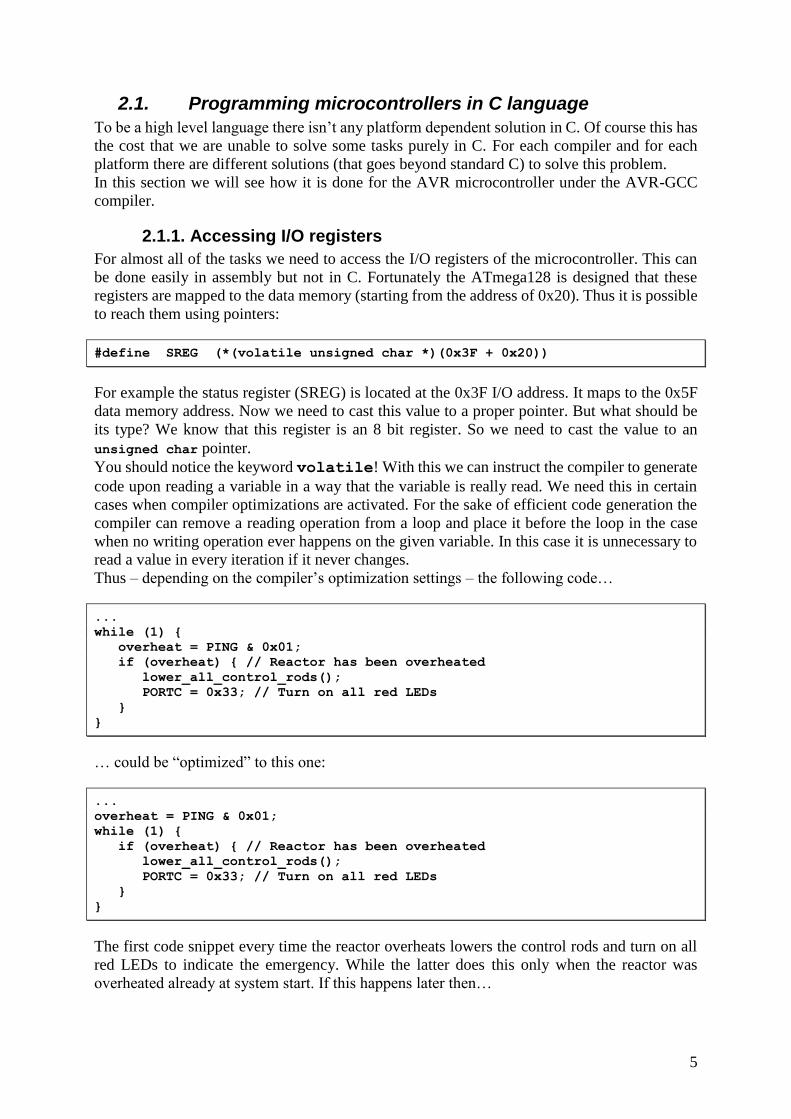
#define SREG (*(volatile unsigned char *)(0x3F + 0x20))
For example the status register (SREG) is located at the 0x3F I/O address. It maps to the 0x5F
data memory address. Now we need to cast this value to a proper pointer. But what should be
its type? We know that this register is an 8 bit register. So we need to cast the value to an
unsigned char pointer.
You should notice the keyword volatile! With this we can instruct the compiler to generate
code upon reading a variable in a way that the variable is really read. We need this in certain
cases when compiler optimizations are activated. For the sake of efficient code generation the
compiler can remove a reading operation from a loop and place it before the loop in the case
when no writing operation ever happens on the given variable. In this case it is unnecessary to
read a value in every iteration if it never changes.
Thus – depending on the compiler’s optimization settings – the following code…
...
while (1) {
overheat = PING & 0x01;
if (overheat) { // Reactor has been overheated
lower_all_control_rods();
PORTC = 0x33; // Turn on all red LEDs
}
}
… could be “optimized” to this one:
...
overheat = PING & 0x01;
while (1) {
if (overheat) { // Reactor has been overheated
lower_all_control_rods();
PORTC = 0x33; // Turn on all red LEDs
}
}
The first code snippet every time the reactor overheats lowers the control rods and turn on all
red LEDs to indicate the emergency. While the latter does this only when the reactor was
overheated already at system start. If this happens later then…
6
It is clear that the problem arises because of the fact that the value of a given memory address
can change independently of the code. In our case the value is altered by hardware. (Another
example when using volatile is needed is the case when the variable is written by code
although the writing operation happens to be within an ISR. An ISR is basically a function
(more details in the following section) but we never call it explicitly. For this reason the
compiler thinks again that the variable is never written.)
The first * (called indirection operator) is needed because at this point we got only a proper
pointer. But for the sake of simplicity we want to use “SREG” exactly the same as a variable
name.
Fortunately we don’t need to type these #define rows for all of the registers. The header file
<avr/io.h> already incorporates them. (This header file accompanies – but not a part of – the
standard C library presented to us by the WinAVR environment.)
2.1.2. Interrupts
It is often necessary to write interrupt service routines (ISR) too. This means we need the
followings:
enable interrupts globally,
enable the given interrupt,
place a jump statement to the right place in the interrupt vector table,
and certainly write the ISR.
These tasks can’t be done in standard C.
For the first task the assembly contains direct statements (sei for globally enable, and cli for
globally disable ITs). The GCC compilers got a language extension called “inline assembly”.
So we can put assembly statements into C code. For example the macros below (sei() and
cli()) use inline assembly to enable and disable global interrupts (without understanding
exactly how AVR-GCC’s inline assembly works we can see that these macros execute the
corresponding assembler statement):
#define sei() __asm__ __volatile__ (”sei” ::)
#define cli() __asm__ __volatile__ (”cli” ::)
To enable the given interrupt we need to set a few bits in the registers belonging to the device
what generates our IT. (Setting the value of an I/O register is described in the previous section.)
The code for the ISR can be placed in a function. But we have to tell the compiler that this
function is not an ordinary one. This is important because the compilers place additional code
to the beginning and to the end of a function. These extra codes needed to pass the function’s
arguments to the code of the function and to return to the calling environment the function’s
return value.
An ISR differs from the above mentioned behavior. It is simpler in the terms that it does not
pass arguments and does not return any value. But in the other hand it is more complicated,
because at the beginning it has to save those registers whose value are altered by the ISR code
and at the end it has to restore these registers and return by a reti (“return from interrupt”)
assembler statement rather than a simple ret. (Saving registers is important because an IT can
happen anytime. So an ISR can interrupt the normal code anywhere. The reti directive equals
to a simple ret instruction (so it gives back execution to the calling code) plus it enables global
interrupts. This is needed because the default behavior of the ATmega128 is to disable global
IT when entering an ISR.)
7
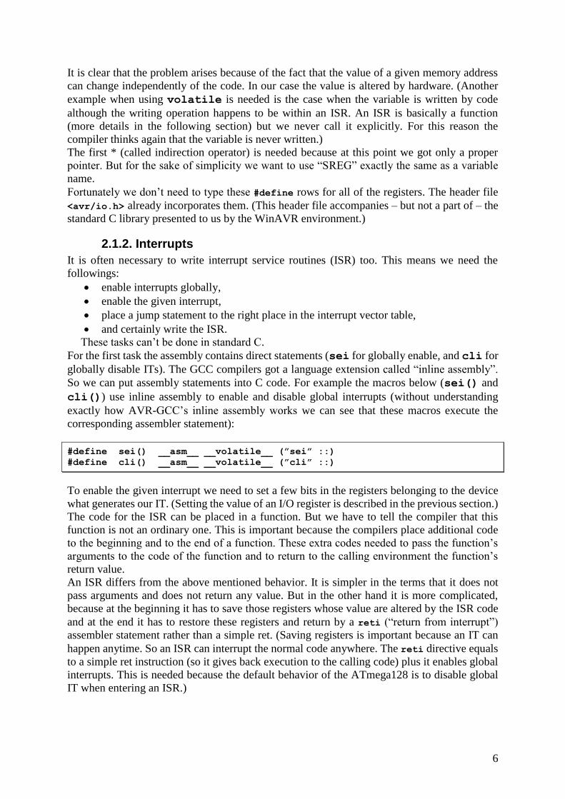
For this purpose we need an other language extension. The GCC compilers allow placing so
called “attributes” at the declaration of a function. So we can define the following macro to
introduce an ISR:
#define ISR(vector) \
void vector (void) __attribute__ ((signal, used)); \
void vector (void)
The signal is an AVR specific attribute. It tells the compiler that this function is an ISR. So
place extra code before the function to save all registers and use a reti as the last instruction
instead of a ret. And used tells the compiler that the code of the function is needed. This is
important because depending on the optimization settings the compiler can “optimize out” code
that is never called. And an ISR is normally never called from the code. It is called when the
appropriate IT happens.
Finally we need to tell the compiler which IT our ISR belongs to. So where should it place a
jump instruction in the interrupt vector table. (When an IT happens the execution is directed to
the place belonging to that IT in the interrupt vector table. The space for the interrupts in this
table is only enough for one or two assembly instructions. This is why we need here a jump to
the real ISR). The compiler does it for us if we give a special name for our ISR. For example
the following code makes an ISR for the 4th external interrupt:
ISR(INT4_vect) {
// Do something…
}
Fortunately we don’t need to type these macros because the header file <avr/interrupt.h>
already incorporates them.
2.1.3. Using standard I/O
Using standard I/O is also not a self-evident task concerning microcontrollers. To where writes
printf()? From where reads scanf()? In most of the cases we don’t have a huge display or a
keyboard with many buttons. Thus it is common in embedded systems to forward standard I/O
operations to a serial port. This makes it easily possible to connect our device to a PC. And
running a serial terminal on the computer, we get the missing display and keyboard.
Furthermore there is an LCD display (4x20 characters) on the panel. We can print smaller
messages onto it.
Now we know to where can we write and from where can we read. The question is how can we
tell the standard I/O manipulating functions to use the serial port (or LCD display) as their input
/ output? First of all we have to make routines that are capable to write or read single characters
to or from the given periphery. After this we have to bind somehow these routines to the
standard I/O functions.
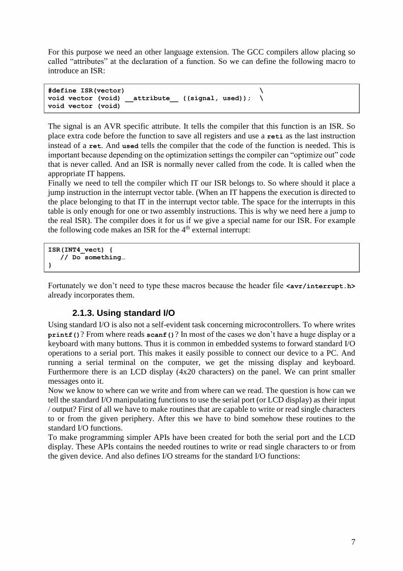
To make programming simpler APIs have been created for both the serial port and the LCD
display. These APIs contains the needed routines to write or read single characters to or from
the given device. And also defines I/O streams for the standard I/O functions:
8
int serial_putc(char character, FILE * stream) { ... }
int serial_getc() { ... }
int LCD_putc (char character, FILE * stream) { ... }
FILE serial_stdout = FDEV_SETUP_STREAM(serial_putc,NULL,_FDEV_SETUP_WRITE);
FILE serial_stdin = FDEV_SETUP_STREAM(NULL,serial_getc,_FDEV_SETUP_READ );
FILE LCD_stdout = FDEV_SETUP_STREAM(LCD_putc, NULL, _FDEV_SETUP_WRITE);
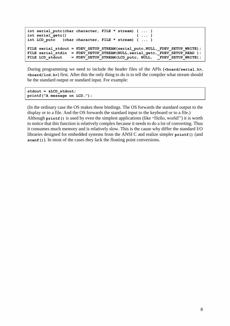
During programming we need to include the header files of the APIs (<board/serial.h>,
<board/lcd.h>) first. After this the only thing to do is to tell the compiler what stream should
be the standard output or standard input. For example:
stdout = &LCD_stdout;
printf(”A message on LCD.”);
(In the ordinary case the OS makes these bindings. The OS forwards the standard output to the
display or to a file. And the OS forwards the standard input to the keyboard or to a file.)
Although printf() is used by even the simplest applications (like “Hello, world!”) it is worth
to notice that this function is relatively complex because it needs to do a lot of converting. Thus
it consumes much memory and is relatively slow. This is the cause why differ the standard I/O
libraries designed for embedded systems from the ANSI C and realize simpler printf() (and
scanf()). In most of the cases they lack the floating point conversions.
9
2.2. Embedded operating systems
2.2.1. The embedded OS as software architecture
The following code example shows the structure of the embedded OS as software architecture:
void interrupt Device1 (void) {
!! Handle Device 1 time critical part
!! Set signal to Device1_task
}
void interrupt Device2 (void) {
!! Handle Device 2 time critical part
!! Set signal to Device2_task
}
...
void Device1_task (void) {
!! Wait for signal to Device1_task
!! Handle Device 1
}
void Device2_task (void) {
!! Wait for signal to Device2_task
!! Handle Device 2
}
...
void main (void) {
!! Initialize OS
!! Start OS scheduler
}
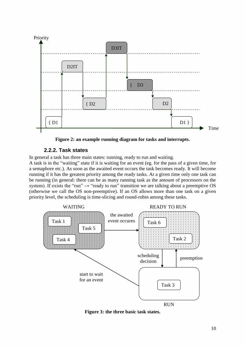
ISRs do the handling of time critical parts of the devices. This is because even the lowest
priority IT is able to interrupt the highest priority task5. In turn we should place only that part
of code to an ISR that can’t be done in a task!
Probably one of the main advantages of an embedded OS is the possibility to give tasks
priorities. The more important a task is, the less response time is needed for it. Further advantage
is that the embedded OS-es provide services for shared resource handling, inter-task
communication and synchronization.
However the disadvantage is the need of greater computing time and memory.
On the following figure you can see an example time diagram for executing tasks and Its:
5 the terms of task, process and thread is often confusing even in the terminology. This guide interprets these as follows:
Task: is a functional unit to do something,
Process: is an executional unit. The processes are protected against each other, they can’t see each others memory. Thus the
inter-process communication is relatively complicated and context switching needs a great overhead, Thread: is also an executional unit. Sometimes it is called „lightweight process”. It refers to the fact that there is much less
protection between threads as between processes. Threads can see each others memory, so they can communicate easily and
context switching doesn’t mean such a great overhead.
10
Figure 2: an example running diagram for tasks and interrupts.
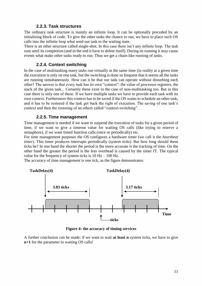
2.2.2. Task states
In general a task has three main states: running, ready to run and waiting.
A task is in the “waiting” state if it is waiting for an event (eg. for the pass of a given time, for
a semaphore etc.). As soon as the awaited event occurs the task becomes ready. It will become
running if it has the greatest priority among the ready tasks. At a given time only one task can
be running (in general: there can be as many running task as the amount of processors on the
system). If exists the “run” → “ready to run” transition we are talking about a preemptive OS
(otherwise we call the OS non-preemptive). If an OS allows more than one task on a given
priority level, the scheduling is time-slicing and round-robin among these tasks.
Figure 3: the three basic task states.
{ D1
{ D3
}
{ D2
D2IT
D3IT
D1 }
D2
}
Priority
Time
Task 1
Task 4 Task 2
Task 5
Task 3
Task 6
start to wait
for an event
the awaited
event occures
scheduling
decision preemption
READY TO RUN WAITING
RUN
11
2.2.3. Task structures
The ordinary task structure is mainly an infinite loop. It can be optionally preceded by an
initializing block of code. To give the other tasks the chance to run, we have to place such OS
calls into the infinite loop what send our task to the waiting state.
There is an other structure called single-shot. In this case there isn’t any infinite loop. The task
runs until its completion (and in the end it have to delete itself). During its running it may cause
events what make other tasks ready to run. Thus we get a chain-like running of tasks.
2.2.4. Context switching
In the case of multitasking many tasks run virtually at the same time (in reality at a given time
the execution is only on one task, but the switching is done so frequent that it seems all the tasks
are running simultaneously. How can it be that our task can operate without disturbing each
other? The answer is that every task has its own “context”: the value of processor registers, the
stack of the given task... Certainly these exist in the case of non-multitasking too. But in this
case there is only one of these. If we have multiple tasks we have to provide each task with its
own context. Furthermore this context has to be saved if the OS wants to schedule an other task,
and it has to be restored if the task get back the right of execution. The saving of one task’s
context and then the restoring of an others called “context-switching”.
2.2.5. Time management
Time management is needed if we want to suspend the execution of tasks for a given period of
time, if we want to give a timeout value for waiting OS calls (like trying to reserve a
semaphore), if we want timed function calls (once or periodically) etc.
For time management purposes the OS configures a hardware timer (we call it the heartbeat
timer). This timer produces interrupts periodically (system ticks). But how long should these
ticks be? In one hand the shorter the period is the more accurate is the tracking of time. On the
other hand the greater the period is the less overhead is caused by the timer IT. The typical
value for the frequency of system ticks is 10 Hz – 100 Hz.
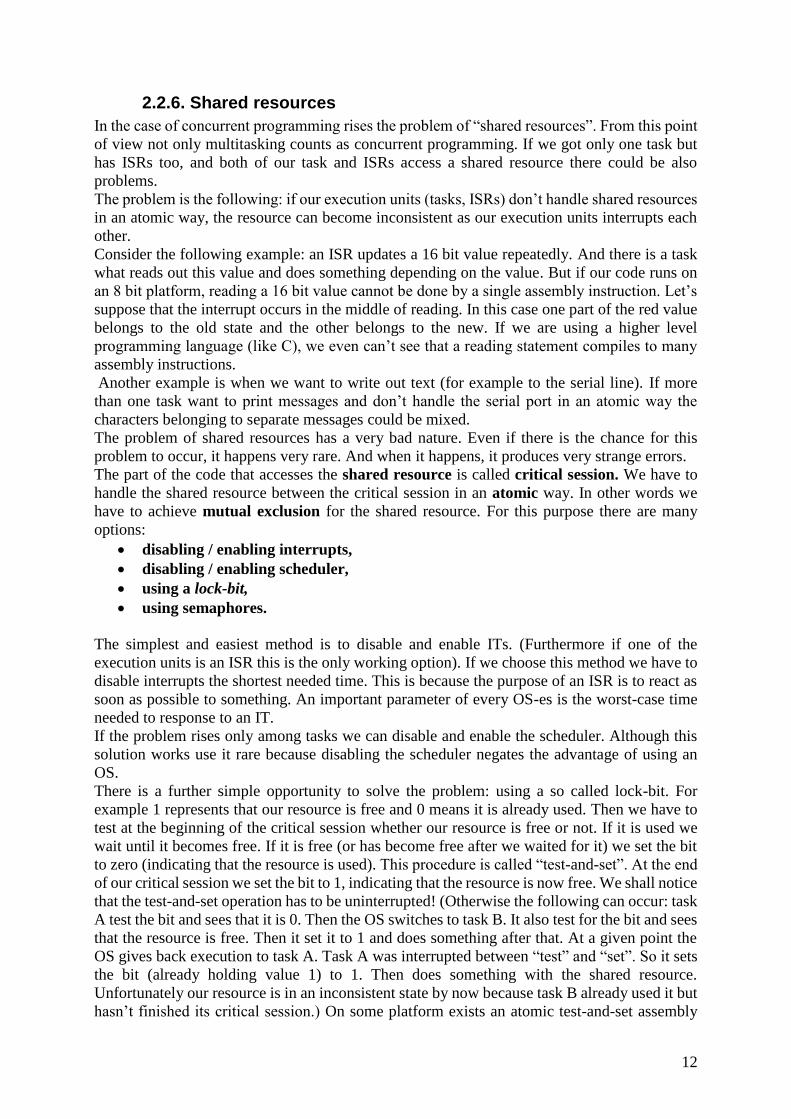
The accuracy of time management is one tick, as the figure demonstrates:
Figure 4: the accuracy of timing services
A further conclusion can be made: if we want to wait at least n system ticks, we have to give
n+1 for the parameter to waiting OS calls!
TaskDelay(4) TaskDelay(4)
3.83 ticks 3.17 ticks
Time
ticks
12
2.2.6. Shared resources
In the case of concurrent programming rises the problem of “shared resources”. From this point
of view not only multitasking counts as concurrent programming. If we got only one task but
has ISRs too, and both of our task and ISRs access a shared resource there could be also
problems.
The problem is the following: if our execution units (tasks, ISRs) don’t handle shared resources
in an atomic way, the resource can become inconsistent as our execution units interrupts each
other.
Consider the following example: an ISR updates a 16 bit value repeatedly. And there is a task
what reads out this value and does something depending on the value. But if our code runs on
an 8 bit platform, reading a 16 bit value cannot be done by a single assembly instruction. Let’s
suppose that the interrupt occurs in the middle of reading. In this case one part of the red value
belongs to the old state and the other belongs to the new. If we are using a higher level
programming language (like C), we even can’t see that a reading statement compiles to many
assembly instructions.
Another example is when we want to write out text (for example to the serial line). If more
than one task want to print messages and don’t handle the serial port in an atomic way the
characters belonging to separate messages could be mixed.
The problem of shared resources has a very bad nature. Even if there is the chance for this
problem to occur, it happens very rare. And when it happens, it produces very strange errors.
The part of the code that accesses the shared resource is called critical session. We have to
handle the shared resource between the critical session in an atomic way. In other words we
have to achieve mutual exclusion for the shared resource. For this purpose there are many
options:
disabling / enabling interrupts,
disabling / enabling scheduler,
using a lock-bit,
using semaphores.
The simplest and easiest method is to disable and enable ITs. (Furthermore if one of the
execution units is an ISR this is the only working option). If we choose this method we have to
disable interrupts the shortest needed time. This is because the purpose of an ISR is to react as
soon as possible to something. An important parameter of every OS-es is the worst-case time
needed to response to an IT.
If the problem rises only among tasks we can disable and enable the scheduler. Although this
solution works use it rare because disabling the scheduler negates the advantage of using an
OS.
There is a further simple opportunity to solve the problem: using a so called lock-bit. For
example 1 represents that our resource is free and 0 means it is already used. Then we have to
test at the beginning of the critical session whether our resource is free or not. If it is used we
wait until it becomes free. If it is free (or has become free after we waited for it) we set the bit
to zero (indicating that the resource is used). This procedure is called “test-and-set”. At the end
of our critical session we set the bit to 1, indicating that the resource is now free. We shall notice
that the test-and-set operation has to be uninterrupted! (Otherwise the following can occur: task
A test the bit and sees that it is 0. Then the OS switches to task B. It also test for the bit and sees
that the resource is free. Then it set it to 1 and does something after that. At a given point the
OS gives back execution to task A. Task A was interrupted between “test” and “set”. So it sets
the bit (already holding value 1) to 1. Then does something with the shared resource.
Unfortunately our resource is in an inconsistent state by now because task B already used it but
hasn’t finished its critical session.) On some platform exists an atomic test-and-set assembly
13
instruction (TAS). If this is not the case, we have to disable Its before “test” and reenable them
after “set”.
There is a more sophisticated solution called semaphore. A semaphore is basically a lock-bit.
The difference is that it is an OS service. This means if a task have to wait a semaphore the OS
put it to a waiting state. (Meanwhile if a task wait for a lock-bit to become free, it doesn’t go to
waiting state rather it is running and endlessly checks whether the lock-bit is free or not. ).
Semaphores were invented originally for trains. For programming purposes it was invented by
the Dutch Edgser Dijkstra in the mid 60’s. There are two basic operations on it: P() and V()6.
The first is basically the TAS operation (it is also called sometimes Wait() or Pend(). The second
is the releasing of the semaphore (sometimes called Signal() or Post()). The P() operation
decreases the value of the semaphore by 1 (if it is greater than 0). If the semaphore is 0, P()
waits until it is freed up. The operation V() increases the value by 1. If the maximal value of
the semaphore is 1, then we are talking about a binary semaphore. When the maximal value
is greater than 1 we call it a counting semaphore. We have to be careful with semaphores.
They are great tools against the problem of shared resources, but we have to avoid misusing
them:
we forget to wait / release a semaphore,
we wait or release a wrong semaphore,
a deadlock (called also deadly embrace) can occur (task A waits for semaphore 1 what
is used by task B, and task B is waiting for semaphore 2 what is used by task A),
we block a semaphore too long (thus we let other tasks waiting to that semaphore
starve),
priority inversion.
Against the first two mistakes we can offend ourselves with proper coding. Another solution is
to make dedicated functions what handle a resource. The semaphore (what protects this
resource) is handled only by these functions. So if we call these functions to access the resource,
the protecting semaphore is automatically used and handled in the proper way).
Against deadlock an easy solution is to reserve all the needed semaphores at once. Another way
is to reserve all the semaphores in a predefined order. (This can be expressed in general: give
each resource a number. And the tasks should ask only for those resources whose number is
greater than the task already owns.)
Against starving proper coding can give a solution.
About priority inversion see the next chapter.
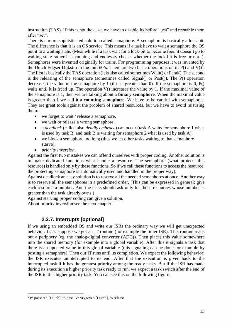
2.2.7. Interrupts [optional]
If we using an embedded OS and write our ISRs the ordinary way we will get unexpected
behavior. Let’s suppose we got an IT routine (for example the timer ISR). This routine reads
out a periphery (eg. the analog/digital converter (ADC)). Then places this value somewhere
into the shared memory (for example into a global variable). After this it signals a task that
there is an updated value in this global variable (this signaling can be done for example by
posting a semaphore). Then our IT runs until its completion. We expect the following behavior:
the ISR executes uninterrupted to its end. After that the execution is given back to the
interrupted task if it has the greatest priority among the ready tasks. But if the ISR has made
during its execution a higher priority task ready to run, we expect a task switch after the end of
the ISR to this higher priority task. You can see this on the following figure:
6 P: passeren [Dutch], to pass. V: vrygeven [Dutch], to release.
14
Figure 5: ISRs in a multitasking environment (as we expect)
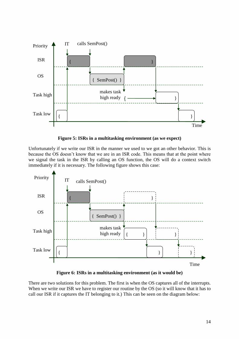
Unfortunately if we write our ISR in the manner we used to we got an other behavior. This is
because the OS doesn’t know that we are in an ISR code. This means that at the point where
we signal the task in the ISR by calling an OS function, the OS will do a context switch
immediately if it is necessary. The following figure shows this case:
Figure 6: ISRs in a multitasking environment (as it would be)
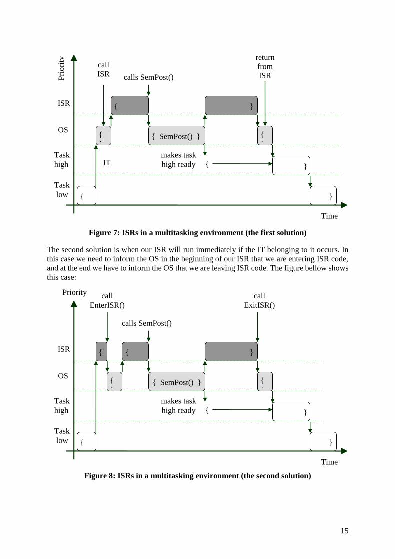
There are two solutions for this problem. The first is when the OS captures all of the interrupts.
When we write our ISR we have to register our routine by the OS (so it will know that it has to
call our ISR if it captures the IT belonging to it.) This can be seen on the diagram below:
Time
{
{
{ SemPost() }
{ ISR
OS
Task high
Task low
}
calls SemPost()
}
}
IT
makes task
high ready
Time
Priority
Time
Priority
{
{ SemPost() }
{ ISR
OS
Task high
Task low
}
calls SemPost()
}
}
IT
makes task
high ready { }
}
15
Figure 7: ISRs in a multitasking environment (the first solution)
The second solution is when our ISR will run immediately if the IT belonging to it occurs. In
this case we need to inform the OS in the beginning of our ISR that we are entering ISR code,
and at the end we have to inform the OS that we are leaving ISR code. The figure bellow shows
this case:
Figure 8: ISRs in a multitasking environment (the second solution)
Time
Pri
ori
ty
{
{
{ SemPost() }
{ ISR
OS
Task
high
Task
low
}
calls SemPost()
}
}
call
ISR
makes task
high ready
{
}
{
}
return
from
ISR
IT
Time
Priority
{
{
{ SemPost() }
{ ISR
OS
Task
high
Task
low
}
calls SemPost()
}
}
call
EnterISR()
makes task
high ready
{
}
{
}
{
call
ExitISR()
16
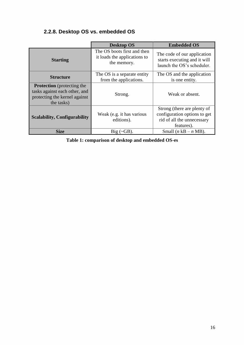
2.2.8. Desktop OS vs. embedded OS
Desktop OS Embedded OS
Starting
The OS boots first and then
it loads the applications to
the memory.
The code of our application
starts executing and it will
launch the OS’s scheduler.
Structure The OS is a separate entity
from the applications.
The OS and the application
is one entity.
Protection (protecting the
tasks against each other, and
protecting the kernel against
the tasks)
Strong. Weak or absent.
Scalability, Configurability Weak (e.g. it has various
editions).
Strong (there are plenty of
configuration options to get
rid of all the unnecessary
features).
Size Big (~GB). Small (n kB – n MB).
Table 1: comparison of desktop and embedded OS-es

17
2.3. Introducing μC/OS7
μC/OS (Micro-Controller Operating System) – as you can guess – is an operating system
designed for microcontrollers. Its main properties are:
its source code is freely accessible,
portable,
highly scalable,
preemptive scheduler,
its execution time is deterministic → real-time,
each task can have different sized stack,
system services: mailbox, queue, semaphore, fixed size memory partition, time
management etc.,
interrupt management (255 level nesting).
2.3.1. The story [reading]
If you have time it is worth to read the story of µC/OS. It’s funny…
http://www.micrium.com/products/rtos/ucos_story.html
2.3.2. The structure of μC/OS
Most of the code of μC/OS is platform independent and written in C. A small amount of code
is platform dependent and written partly in assembly and C.
An application written under µC/OS consists of the application code itself and two additional
header files: one for configuring the OS (os_cfg.h), and a “master include” file (includes.h).
(The includes.h is a container include file. All the needed includes are in it. Both the source
files of the OS and the source file of our application have to include this header file. It makes
our life easier, because if a header file is needed by anybody we can put it in this master include
file. The cost is a slightly increased compiling time (as many of the includes are unnecessary to
some of the source files).)
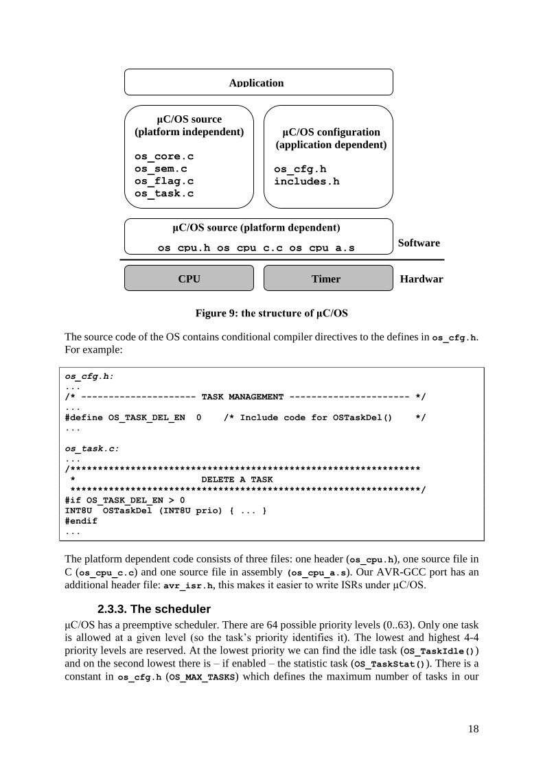
The structure of μC/OS can be seen on figure 11. The fundamentals of the OS are implemented
in os_core.c. Such fundamentals are: initializing of the OS, the scheduler, the idle task, the
statistic task, interrupt handling, programming the heart beat timer… The other source files are
for the various OS services: os_flag.c (event flags), os_mbox.c (message mailboxes),
os_mem.c (memory management), os_mutex.c (mutual exclusion semaphores), os_q.c
(queues), os_sem.c (semaphores), os_task.c (task management), os_time.c (time
management). The file ucos_ii.c is just a container source file. It includes all of the other
above mentioned source files. It is just for the sake of simplicity (we need to compile only this
file instead of all the others one-by-one). The header file ucos_ii.h defines the constants,
variables, typedefs needed by the OS.
7 OS version: 2.52, AVR-GCC port version: 270603
18
Figure 9: the structure of μC/OS
The source code of the OS contains conditional compiler directives to the defines in os_cfg.h.
For example:
os_cfg.h:
...
/* --------------------- TASK MANAGEMENT ---------------------- */
...
#define OS_TASK_DEL_EN 0 /* Include code for OSTaskDel() */
...
os_task.c:
...
/****************************************************************
* DELETE A TASK
****************************************************************/
#if OS_TASK_DEL_EN > 0
INT8U OSTaskDel (INT8U prio) { ... }
#endif
...
The platform dependent code consists of three files: one header (os_cpu.h), one source file in
C (os_cpu_c.c) and one source file in assembly (os_cpu_a.s). Our AVR-GCC port has an
additional header file: avr_isr.h, this makes it easier to write ISRs under µC/OS.
2.3.3. The scheduler
μC/OS has a preemptive scheduler. There are 64 possible priority levels (0..63). Only one task
is allowed at a given level (so the task’s priority identifies it). The lowest and highest 4-4
priority levels are reserved. At the lowest priority we can find the idle task (OS_TaskIdle())
and on the second lowest there is – if enabled – the statistic task (OS_TaskStat()). There is a
constant in os_cfg.h (OS_MAX_TASKS) which defines the maximum number of tasks in our
μC/OS source
(platform independent)
os_core.c
os_sem.c
os_flag.c
os_task.c
os_mbox.c
μC/OS configuration
(application dependent)
os_cfg.h
includes.h
Application
μC/OS source (platform dependent)
os_cpu.h os_cpu_c.c os_cpu_a.s
CPU Timer
Software
Hardwar
e
19
application, and there is an other (OS_LOWEST_PRIO) which defines the lowest accessible
priority. (Warning: in µC/OS the greater value represents the less priority!)
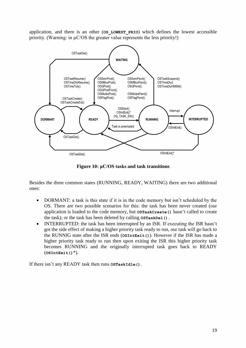
Figure 10: μC/OS tasks and task transitions
Besides the three common states (RUNNING, READY, WAITING) there are two additional
ones:
DORMANT: a task is this state if it is in the code memory but isn’t scheduled by the
OS. There are two possible scenarios for this: the task has been never created (our
application is loaded to the code memory, but OSTaskCreate() hasn’t called to create
the task); or the task has been deleted by calling OSTaskDel().
INTERRUPTED: the task has been interrupted by an ISR. If executing the ISR hasn’t
got the side effect of making a higher priority task ready to run, our task will go back to
the RUNNIG state after the ISR ends (OSIntExit()). However if the ISR has made a
higher priority task ready to run then upon exiting the ISR this higher priority task
becomes RUNNING and the originally interrupted task goes back to READY
(OSIntExit()*).
If there isn’t any READY task then runs OSTaskIdle().
DORMANT READY
WAITING
RUNNING INTERRUPTED
OSSemPost() OSMBoxPost() OSQPost() OSQPostFront() OSMutexPost() OSFlagPost()
OSTaskResume() OSTimeDlyResume()
OSTimeTick()
OSSemPend() OSMBoxPend() OSQPend() OSMutexPend() OSFlagPend()
OSTaskSuspend() OSTimeDly()
OSTimeDlyHMSM()
OSTaskDel()
OSTaskDel()
OSTaskDel()
OSTaskCreate() OSTaskCreateExt()
Task is preempted
Interrupt
OSIntExit()
OSStart() OSIntExit()*
OS_TASK_SW()
OSIntExit()*
20
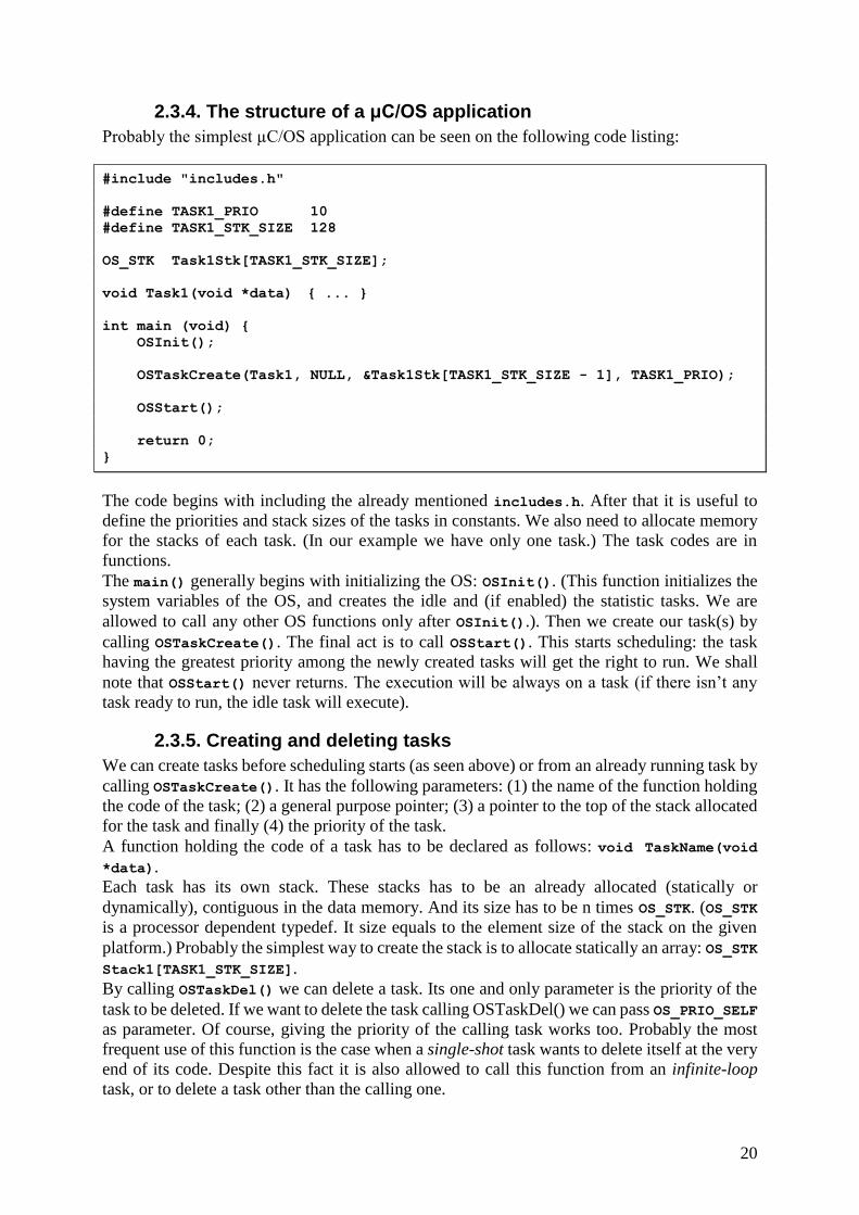
2.3.4. The structure of a μC/OS application
Probably the simplest µC/OS application can be seen on the following code listing:
#include "includes.h"
#define TASK1_PRIO 10
#define TASK1_STK_SIZE 128
OS_STK Task1Stk[TASK1_STK_SIZE];
void Task1(void *data) { ... }
int main (void) {
OSInit();
OSTaskCreate(Task1, NULL, &Task1Stk[TASK1_STK_SIZE - 1], TASK1_PRIO);
OSStart();
return 0;
}
The code begins with including the already mentioned includes.h. After that it is useful to
define the priorities and stack sizes of the tasks in constants. We also need to allocate memory
for the stacks of each task. (In our example we have only one task.) The task codes are in
functions.
The main() generally begins with initializing the OS: OSInit(). (This function initializes the
system variables of the OS, and creates the idle and (if enabled) the statistic tasks. We are
allowed to call any other OS functions only after OSInit().). Then we create our task(s) by
calling OSTaskCreate(). The final act is to call OSStart(). This starts scheduling: the task
having the greatest priority among the newly created tasks will get the right to run. We shall
note that OSStart() never returns. The execution will be always on a task (if there isn’t any
task ready to run, the idle task will execute).
2.3.5. Creating and deleting tasks
We can create tasks before scheduling starts (as seen above) or from an already running task by
calling OSTaskCreate(). It has the following parameters: (1) the name of the function holding
the code of the task; (2) a general purpose pointer; (3) a pointer to the top of the stack allocated
for the task and finally (4) the priority of the task.
A function holding the code of a task has to be declared as follows: void TaskName(void
*data).
Each task has its own stack. These stacks has to be an already allocated (statically or
dynamically), contiguous in the data memory. And its size has to be n times OS_STK. (OS_STK
is a processor dependent typedef. It size equals to the element size of the stack on the given
platform.) Probably the simplest way to create the stack is to allocate statically an array: OS_STK
Stack1[TASK1_STK_SIZE].
By calling OSTaskDel() we can delete a task. Its one and only parameter is the priority of the
task to be deleted. If we want to delete the task calling OSTaskDel() we can pass OS_PRIO_SELF
as parameter. Of course, giving the priority of the calling task works too. Probably the most
frequent use of this function is the case when a single-shot task wants to delete itself at the very
end of its code. Despite this fact it is also allowed to call this function from an infinite-loop
task, or to delete a task other than the calling one.
21
2.3.6. Time management
To be fully functional µC/OS requires the presence of an additional hardware besides the CPU:
a timer unit. (Most of the cases it is a dedicated device integrated into the microcontroller.) This
timer periphery has to generate periodic interrupts. The frequency of the timer interrupts shall
be somewhere between 10 and 100 Hz.
By the help of these ITs the OS is able to suspend the execution of the tasks for a given time.
If we call a pending OS function (eg. OSSemPend()) the default case is to wait infinitely.
Alternatively we can specify a timeout value if time management is functional.
The frequency of this timer is specified in os_cfg.h by the constant OS_TICKS_PER_SEC. We
call one period a “tick”. To put a task into the waiting state for a given amount of time we can
call OSTimeDly(). Its one and only parameter is a 16 bit value specifying the given time in
ticks. If we don’t want to specify the amount of time in ticks we can use OSTimeDlyHMSM(). It
has four parameters to express the amount of delay in: hours, minutes, seconds and
milliseconds.
2.3.7. Semaphores
µC/OS certainly supports the use of semaphores (as the most basic synchronization objects).
The first thing about the semaphore is to create it: OSSemCreate(). It has only one parameter,
a 16 bit number which will be the starting value of the semaphore. (If we want to use our
semaphore to protect resources we shall initialize it to the number of resources. If we want tu
use it just to signal events we have to initialize it to zero. OSSemCreate() returns a pointer. Its
type is OS_EVENT*. We may use this pointer in the future as the handle for the semaphore.
We can wait for a semaphore by calling OSSemPend(). Its first parameter is the soon mentioned
handle, the second is a 16 bit value which expresses the timeout value in ticks (if it is 0, there
is no time limit) and the third parameter is a pointer pointing to a place where the function can
put error messages (in most of the cases it can be NULL).
By calling OSSemPost() we can release a semaphore. It has one parameter: the handle of the
semaphore to be released.
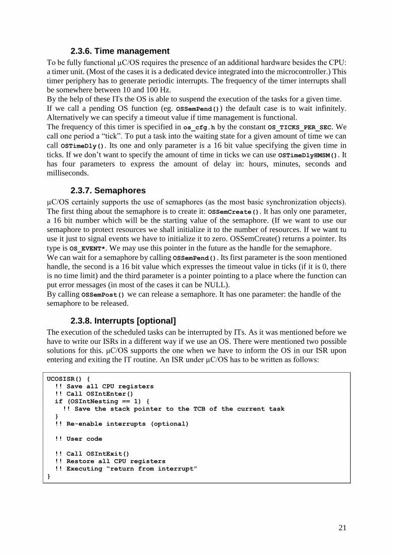
2.3.8. Interrupts [optional]
The execution of the scheduled tasks can be interrupted by ITs. As it was mentioned before we
have to write our ISRs in a different way if we use an OS. There were mentioned two possible
solutions for this. μC/OS supports the one when we have to inform the OS in our ISR upon
entering and exiting the IT routine. An ISR under µC/OS has to be written as follows:
UCOSISR() {
!! Save all CPU registers
!! Call OSIntEnter()
if (OSIntNesting == 1) {
!! Save the stack pointer to the TCB of the current task
}
!! Re-enable interrupts (optional)
!! User code
!! Call OSIntExit()
!! Restore all CPU registers
!! Executing “return from interrupt”
}
22
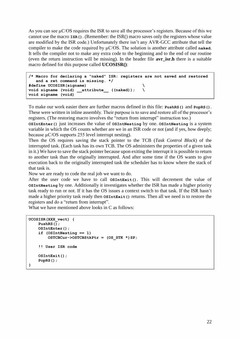
As you can see µC/OS requires the ISR to save all the processor’s registers. Because of this we
cannot use the macro ISR(). (Remember: the ISR() macro saves only the registers whose value
are modified by the ISR code.) Unfortunately there isn’t any AVR-GCC attribute that tell the
compiler to make the code required by µC/OS. The solution is another attribute called naked.
It tells the compiler not to make any extra code to the beginning and to the end of our routine
(even the return instruction will be missing). In the header file avr_isr.h there is a suitable
macro defined for this purpose called UCOSISR():
/* Macro for declaring a "naked" ISR: registers are not saved and restored
and a ret command is missing. */
#define UCOSISR(signame) \
void signame (void) __attribute__ ((naked)); \
void signame (void)
To make our work easier there are further macros defined in this file: PushRS() and PopRS().
These were written in inline assembly. Their purpose is to save and restore all of the processor’s
registers. (The restoring macro involves the “return from interrupt” instruction too.)
OSIntEnter() just increases the value of OSIntNesting by one. OSIntNesting is a system
variable in which the OS counts whether are we in an ISR code or not (and if yes, how deeply;
because µC/OS supports 255 level interrupt nesting).
Then the OS requires saving the stack pointer to the TCB (Task Control Block) of the
interrupted task. (Each task has its own TCB. The OS administers the properties of a given task
in it.) We have to save the stack pointer because upon exiting the interrupt it is possible to return
to another task than the originally interrupted. And after some time if the OS wants to give
execution back to the originally interrupted task the scheduler has to know where the stack of
that task is.
Now we are ready to code the real job we want to do.
After the user code we have to call OSIntExit(). This will decrement the value of
OSIntNesting by one. Additionally it investigates whether the ISR has made a higher priority
task ready to run or not. If it has the OS issues a context switch to that task. If the ISR hasn’t
made a higher priority task ready then OSIntExit() returns. Then all we need is to restore the
registers and do a “return from interrupt”.
What we have mentioned above looks in C as follows:
UCOSISR(XXX_vect) {
PushRS();
OSIntEnter();
if (OSIntNesting == 1)
OSTCBCur->OSTCBStkPtr = (OS_STK *)SP;
!! User ISR code
OSIntExit();
PopRS();
}
23
3. Exercises Before starting with the exercises it is needed to create a certain directory structure and an AVR
Studio project with proper settings.
Creating the directory structure
At the very beginning you should create a directory on drive I: where you want your work to
be located (the name of the directory is not important but it is advisable to avoid any special
characters and spaces). Then you should copy the skeleton files and the source of the uCOS
into that directory in a way that the skeletons should be in the same directory level as header
files includes.h, os_cfg.h and the ucos_src subdirectory.
Creating the AVR Studio project
Project type: AVR GCC
Project name: whatever you want (preferably the same as of the directory)
Create initial file: UNchecked
Create folder: UNchecked
Location: set it to your working directory
Next >>
Debug platform: JTAG ICE
Device: ATmega128
Port: Auto
Finish >>
Setting the AVR Studio project
For the proper operation of the API created for the board the following settings have to be made
after creating the project:
Turn on compiler optimization (at least level -O2): Projects / Configuration Options /
General / Optimization: -O2
Add the library containing the precompiled API: Projects / Configuration Options /
Libraries / libboard.a / Add Library
After the project has been properly configured we can start adding the first skeleton file to the
project (right click on the list at the left on the item Source Files / Add Existing Source File(s)…
If you want to move to the next exercise then simply remove the actual skeleton from the project
(right click on its name in the list / Remove File from Project), then add the next skeleton to the
project the same way you did with the first exercise. And so on...
The first three exercises aim to demonstrate the specialties of programming a microcontroller
in C (without any embedded OS).
The other exercises show the use of a single µC/OS service.
1. Accessing the I/O registers of the microcontroller
“Running lights”: write an application (using the skeleton file 1_IO_registers.c) which lit a
LED on the board. The light shall start at LED0 and must jump forward LED7 step-by-step. If
it reached LED7 it has to return to LED0. The speed of jumping should be slow enough to be
seen. For delaying purposes use the functions provided by <util/delay.h>!
(Optional: if You are done extend the application by the capability to stop jumping while the
button INT is pressed (if it is released jumping shall continue)! Do not use interrupts to handle
the button, just poll it!)
24
2. Interrupts
„Switching LEDs”: write an application (using the skeleton file 2_ISR.c) which lit a LED on
the board if the INT button is pressed and darkens it when the button is pressed again! Use
interrupts!
3. Stdio operations
„Typewriter”: write an application (extending 3_stdio.c) to print characters (received from
the serial port) to the LCD panel! Initialize the stdin and stdout streams by the corresponding
streams provided by the API (<board/lcd.h>, <board/serial.h>). After this You can use
C’s standard I/O functions.
(To send characters to the serial port You may use Hyperterminal under Windows. You have
to set: 9600 baud, 8 data bits, no parity, 1 stop bit and no flow control.)
4a. μC/OS – a single task
By the help of 4a_ucos_task.c write a µC/OS application consisting of only one task! This
task prints the version of the OS to the LCD. (You can use the predefined constant called
OS_VERSION.) Let the structure of the task be single-shot!
4b. μC/OS – time management
By extending the 4b_time.c skeleton file write two additional tasks (structured as infinite
loop)! One of them has to count seconds on the LCD! The other has to be the already known
“running light”. For delaying purposes use the OS services (OSTimeDly() and/or
OSTimeDlyHMSM())!
Could we use the delaying functions (used in the first exercise) instead of the OS time delaying
routines (yes/no, why)?
4c. μC/OS – semaphores (guarding shared resources)
Write an application consisting two tasks by filling out the skeleton file 4c_ucos_sem.c!
The task with lower priority prints out to the serial interface the following line at every
second:
Students: Name1 (Neptun1) + Name2 (Neptun2), Uptime = mm:ss\n
(Where Name1 and Name2 are the names of the students (without any non-standard
characters), Neptun1 and Neptun2 are the Neptun-codes of the students, mm and ss are the
minutes and seconds components of the time elapsed since power on.)
The task with higher priority prints out also to the serial interface, but only when BT0 is
pressed (the very moment of pressing the button is what matters and not the continuous
pressed state). The following line shall be printed out:
BT0: bbb\n
Where bbb is the number of BT0 presses since power on.
Care must be taken to avoid starving out the lower priority task by the higher priority task!
Furthermore it is advisable to debounce the button (for the sake of simplicity let’s assume
that the bouncing effect lasts for maximum 10ms). Hint: the above mentioned two goals can
be satisfied at once by calling a properly parametrized OS function.
Try to press BT0 at the very moment when the time counting task prints out to the serial
interface. After a few attempts it can be done.
What do You think the cause is? Solve the problem by using a semaphore!
25
4d. μC/OS – interrupts (and semaphores for event signaling) [optional]
“LCD backlight control”: using the skeleton file 4d_ucos_isr.c make an interrupt service
routine under μC/OS. The only duty of this routine is to read out the A/D converter value to a
global variable every time when A/D conversion completes. (The source of the converter can
be the potentiometer, the opto-resistor or the analog BNC input.)
You have to make also a task. This task controls the backlight based upon the value stored by
the ISR in the global variable.
The ISR have to inform the task by a semaphore that a new value is presented in the global
variable.
Handle the A/D converter by calling the API functions. Initialize it in single conversion mode.
26
4. Reference In this section we will discuss the functions of the OS and the API made for the panel.
4.1. μC/OS functions
During the explanation of µC/OS functions we will use some predefined types declared in the
source code of the OS.
(For example INT8U is an 8 bit wide unsigned integer. INT32S is a 32 bit wide signed integer.
And so on… OS_STK is the already mentioned type to represent a single task element.)
4.1.1. Task management
CREATING A TASK
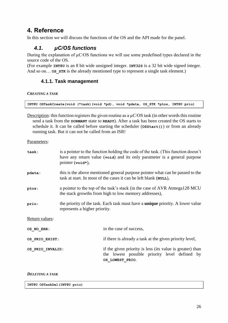
INT8U OSTaskCreate(void (*task)(void *pd), void *pdata, OS_STK *ptos, INT8U prio)
Description: this function registers the given routine as a µC/OS task (in other words this routine
send a task from the DORMANT state to READY). After a task has been created the OS starts to
schedule it. It can be called before starting the scheduler (OSStart()) or from an already
running task. But it can not be called from an ISR!
Parameters:
task: is a pointer to the function holding the code of the task. (This function doesn’t
have any return value (void) and its only parameter is a general purpose
pointer (void*),
pdata: this is the above mentioned general purpose pointer what can be passed to the
task at start. In most of the cases it can be left blank (NULL),
ptos: a pointer to the top of the task’s stack (in the case of AVR Atmega128 MCU
the stack growths from high to low memory addresses),
prio: the priority of the task. Each task must have a unique priority. A lower value
represents a higher priority.
Return values:
OS_NO_ERR: in the case of success,
OS_PRIO_EXIST: if there is already a task at the given priority level,
OS_PRIO_INVALID: if the given priority is less (its value is greater) than
the lowest possible priority level defined by
OS_LOWEST_PRIO.
DELETING A TASK
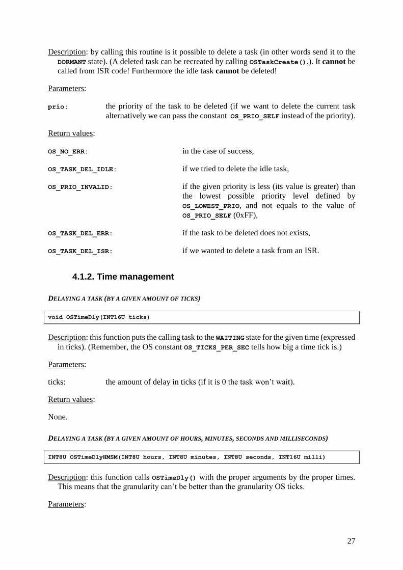
INT8U OSTaskDel(INT8U prio)
27
Description: by calling this routine is it possible to delete a task (in other words send it to the
DORMANT state). (A deleted task can be recreated by calling OSTaskCreate().). It cannot be
called from ISR code! Furthermore the idle task cannot be deleted!
Parameters:
prio: the priority of the task to be deleted (if we want to delete the current task
alternatively we can pass the constant OS_PRIO_SELF instead of the priority).
Return values:
OS_NO_ERR: in the case of success,
OS_TASK_DEL_IDLE: if we tried to delete the idle task,
OS_PRIO_INVALID: if the given priority is less (its value is greater) than
the lowest possible priority level defined by
OS_LOWEST_PRIO, and not equals to the value of
OS_PRIO_SELF (0xFF),
OS_TASK_DEL_ERR: if the task to be deleted does not exists,
OS_TASK_DEL_ISR: if we wanted to delete a task from an ISR.
4.1.2. Time management
DELAYING A TASK (BY A GIVEN AMOUNT OF TICKS)
void OSTimeDly(INT16U ticks)
Description: this function puts the calling task to the WAITING state for the given time (expressed
in ticks). (Remember, the OS constant OS_TICKS_PER_SEC tells how big a time tick is.)
Parameters:
ticks: the amount of delay in ticks (if it is 0 the task won’t wait).
Return values:
None.
DELAYING A TASK (BY A GIVEN AMOUNT OF HOURS, MINUTES, SECONDS AND MILLISECONDS)
INT8U OSTimeDlyHMSM(INT8U hours, INT8U minutes, INT8U seconds, INT16U milli)
Description: this function calls OSTimeDly() with the proper arguments by the proper times.
This means that the granularity can’t be better than the granularity OS ticks.
Parameters:
28
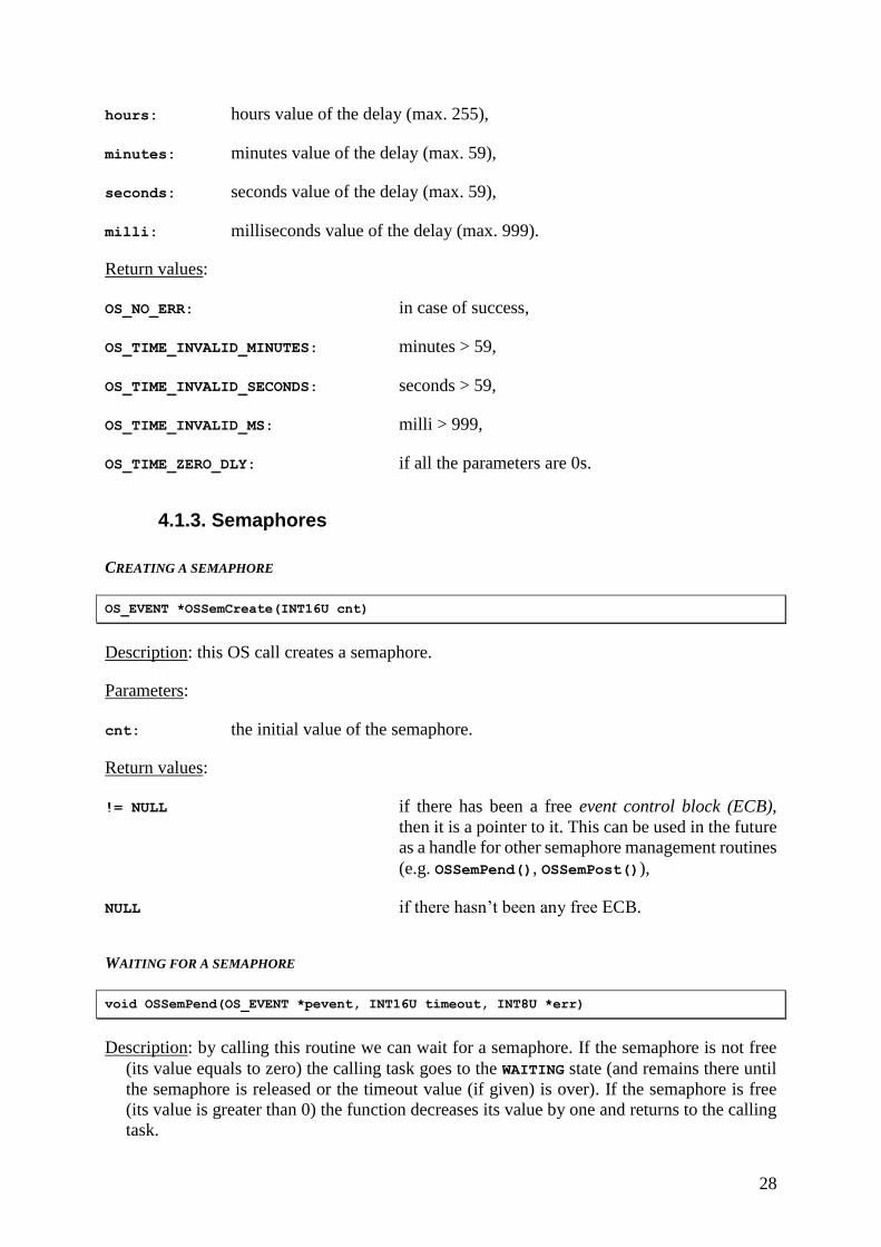
hours: hours value of the delay (max. 255),
minutes: minutes value of the delay (max. 59),
seconds: seconds value of the delay (max. 59),
milli: milliseconds value of the delay (max. 999).
Return values:
OS_NO_ERR: in case of success,
OS_TIME_INVALID_MINUTES: minutes > 59,
OS_TIME_INVALID_SECONDS: seconds > 59,
OS_TIME_INVALID_MS: milli > 999,
OS_TIME_ZERO_DLY: if all the parameters are 0s.
4.1.3. Semaphores
CREATING A SEMAPHORE
OS_EVENT *OSSemCreate(INT16U cnt)
Description: this OS call creates a semaphore.
Parameters:
cnt: the initial value of the semaphore.
Return values:
!= NULL if there has been a free event control block (ECB),
then it is a pointer to it. This can be used in the future
as a handle for other semaphore management routines
(e.g. OSSemPend(), OSSemPost()),
NULL if there hasn’t been any free ECB.
WAITING FOR A SEMAPHORE
void OSSemPend(OS_EVENT *pevent, INT16U timeout, INT8U *err)
Description: by calling this routine we can wait for a semaphore. If the semaphore is not free
(its value equals to zero) the calling task goes to the WAITING state (and remains there until
the semaphore is released or the timeout value (if given) is over). If the semaphore is free
(its value is greater than 0) the function decreases its value by one and returns to the calling
task.
29
Parameters:
pevent the handle of the semaphore (a pointer to the semaphore’s ECB),
timeout if it is not zero, it defines the maximum amount of time (expressed in ticks)
the function will wait. If it is 0, the function will wait endlessly until the
semaphore becomes free,
err it is a pointer to a memory area in which the function can place its error codes
(most of the cases it can be a NULL pointer). The possible error codes:
OS_NO_ERR in case of success,
OS_TIMEOUT the given timeout is over,
OS_ERR_EVENT_TYPE if we have passed a pointer (as handle) to a wrong
type of ECB (e.g. for a mailbox, not for a semaphore),
OS_ERR_PEND_ISR if we have called the function from an ISR,
OS_ERR_PEVENT_NULL if pevent is NULL.
Return value:
None.
RELEASING A SEMAPHORE
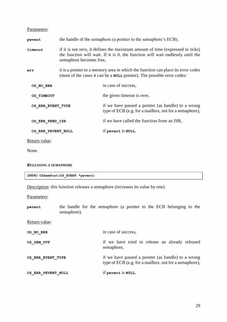
INT8U OSSemPost(OS_EVENT *pevent)
Description: this function releases a semaphore (increases its value by one).
Parameters:
pevent the handle for the semaphore (a pointer to the ECB belonging to the
semaphore).
Return value:
OS_NO_ERR in case of success,
OS_SEM_OVF if we have tried to release an already released
semaphore,
OS_ERR_EVENT_TYPE if we have passed a pointer (as handle) to a wrong
type of ECB (e.g. for a mailbox, not for a semaphore),
OS_ERR_PEVENT_NULL if pevent is NULL.

30
4.2. Description of the APIs made for the board
To make it easier to program the devices on the board (LCD panel, serial port, A/D converter)
there are APIs for them. Their header files are located in a subdirectory called “board” under
the default include path. We provide the precompiled codes for the APIs. This is located in the
default library path in the file „libboard.a”.
The standard C library shipped for by the AVR-GCC defines some integer types (<stdint.h>).
These are 8, 16, 32 and 64 bit wide, and can be signed and unsigned. They have easy to
remember names. For example the 8 bit wide unsigned type is called uint8_t, the 64 bit wide
signed is called int64_t and so on…
(The source of μC/OS also defines integer types like the ones above. We are not using these
because we want the API to be usable without the OS too.)
4.2.1. LCD management
There is a 4x20 character LCD module on the experiment board with LED backlight. The LCD
API makes it easier to use the LCD panel. Before using we need to include the appropriate
header file: #include <board/lcd.h>. Warning: for the API to operate properly we need to
enable compiler optimization. This can be done by setting the optimization switch to at least "-
O2". Under AVR Studio 4.13 (b528): Projects / Configuration Options / General /
Optimization: -O2.
If we want to use the LCD as the standard output we need to place the following line to the
code: stdout = &LCD_stdout;.
There are a few special characters. These are implemented as follows:
\n: carriage return + line feed,
\r: carriage return,
\t: horizontal tabulator,
\v: vertical tabulator. (It jumps from one even row to the other and jumps from one odd
row to the other.)
\a: "Alarm". “Blinks” the display.
INITIALIZE THE LCD PANEL
void LCD_init()
Description: initialize the LCD, hides the cursor and turns on backlight. It has to be called
before calling any other function belonging to the LCD API!
Parameters: none.
Return values: none.
TURNS ON BACKLIGHT
void LCD_light_on();
Description: turns on the LCD’s backlight at maximal value.
Parameters: none.
Return value: none.
31
TURN OFF BACKLIGHT
void LCD_light_off();
Description: turns off the LCD’s backlight.
Parameters: none.
Return value: none.
TURN ON BACKLIGHT (TO A GIVEN BRIGHTNESS)
void LCD_light(uint8_t intensity);
Description: this sets the LCD’s backlight to a brightness level in the 0…255 interval.
Parameters:
intensity the desired brightness: 0 (turn off) … 255 (turn on).
Return value: none.
4.2.2. Handling the serial port
There is an RS232 port on the panel (warning: this is not the one that is used to program the
device!!!). Before using the serial port API, we need to include its header file: #include
<board/serial.h>. Warning: the API handles the port without any ISR. This means all
functions what read or write from or to the port block until their job is done!
If we want to use the serial port as the standard input or output we have to place the following
lines to the code: stdin = &serial_stdin; and / or: stdout = &serial_stdout;.
All character is sent to the port unchanged expect the “new line” (\n) which is sent with an
additional “carriage return” (\r).
INITIALIZING THE SERIAL INTERFACE
void serial_init()
Description: initialize the serial line to 9600 baud, 8 data bit, 1 stop bit and no parity bit.
Parameters: none.
Return value: none.
SENDING DATA
void serial_transmit(uint8_t data)
Description: send a byte over the serial line. (Warning: the function block until the sending
buffer is free!)
Parameters:
32
data the 8 bit wide data to be sent.
Return value: none.
RECEIVE DATA
uint8_t serial_receive()
Description: receive one byte over the serial line. (Warning: the function blocks until data is
received!)
Parameters: none.
Return value: the received byte.
4.2.3. Using the A/D converter
There is an A/D converter unit located in the microcontroller. It has many inputs. One is
connected to the BNC input on the panel, one is to a NTK (negative thermal coefficient resistor),
one is to an optoresistor and one is to a potentiometer. The API sets the converter to use
interrupts. The digitalized values are 10 bit wide. The converter can operate in one of two
operation modes: single conversion (before every conversion the converter has to be started) or
free running (after every conversion the converter starts an other endlessly). (In the
measurement always use single conversion!)
INITIALIZING THE A/D CONVERTER
void ADC_init(uint8_t channel, uint8_t mode)
Description: this function initializes the converter, sets the desired input channel and
operation mode. Warning: call this function before any other A/D functions!
Parameters:
channel the desired input channel:
ADC_AIN the analog BNC input,
ADC_NTK the NTK resistor,
ADC_OPTO the optoresistor,
ADC_POT the potentiometer.
mode the desired operating mode:
ADC_SINGLE single conversion,
ADC_RUNNING free running.
Return value: none.
33
STARTING CONVERSION
void ADC_start()
Description: starts the analog to digital conversion.
Parameters: none.
Return value: none.
READ THE CONVERTED VALUE
uint16_t ADC_read()
Description: this function reads out the result of the conversion. It is 10 bit wide value (put into
a 16 bit wide integer).
Parameters: none.
Return value: the red value.
SET CHANNEL
void ADC_set_channel(uint8_t channel)
Description: by calling this function we can change the selected input channel. (If we call this
routine while a conversion is in process, that conversion will belong to the old channel and
the next conversion will use the newly set channel.)
Parameters:
channel the desired input channel:
ADC_AIN the analog BNC input,
ADC_NTK the NTK resistor,
ADC_OPTO the optoresistor,
ADC_POT the potentiometer.
Return value: none.
SET OPERATING MODE
void ADC_set_mode(uint8_t mode)
Description: by calling this function we can change the operating mode of the converter.
Parameters:
34
mode the desired operating mode:
ADC_SINGLE single conversion,
ADC_RUNNING free running.
Return value: none.
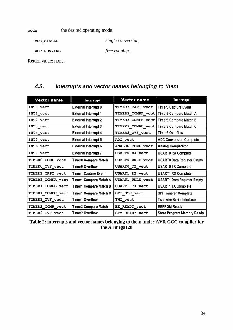
4.3. Interrupts and vector names belonging to them
Vector name Interrupt Vector name Interrupt
INT0_vect External Interrupt 0 TIMER3_CAPT_vect Timer3 Capture Event
INT1_vect External Interrupt 1 TIMER3_COMPA_vect Timer3 Compare Match A
INT2_vect External Interrupt 2 TIMER3_COMPB_vect Timer3 Compare Match B
INT3_vect External Interrupt 3 TIMER3_COMPC_vect Timer3 Compare Match C
INT4_vect External Interrupt 4 TIMER3_OVF_vect Timer3 Overflow
INT5_vect External Interrupt 5 ADC_vect ADC Conversion Complete
INT6_vect External Interrupt 6 ANALOG_COMP_vect Analog Comparator
INT7_vect External Interrupt 7 USART0_RX_vect USART0 RX Complete
TIMER0_COMP_vect Timer0 Compare Match USART0_UDRE_vect USART0 Data Register Empty
TIMER0_OVF_vect Timer0 Overflow USART0_TX_vect USART0 TX Complete
TIMER1_CAPT_vect Timer1 Capture Event USART1_RX_vect USART1 RX Complete
TIMER1_COMPA_vect Timer1 Compare Match A USART1_UDRE_vect USART1 Data Register Empty
TIMER1_COMPB_vect Timer1 Compare Match B USART1_TX_vect USART1 TX Complete
TIMER1_COMPC_vect Timer1 Compare Match C SPI_STC_vect SPI Transfer Complete
TIMER1_OVF_vect Timer1 Overflow TWI_vect Two-wire Serial Interface
TIMER2_COMP_vect Timer2 Compare Match EE_READY_vect EEPROM Ready
TIMER2_OVF_vect Timer2 Overflow SPM_READY_vect Store Program Memory Ready
Table 2: interrupts and vector names belonging to them under AVR GCC compiler for
the ATmega128
35
5. Test questions
Atmel AVR ATmega128 (hardware and programming in assembly):
1. What is the architecture of the ATmega128 (Harvard or Neumann)? In other words:
are the program and data memory separated or not?
2. In the ATmega128 (like in every microcontroller) there is a few peripheral devices.
Can You name three of them?
3. Besides the register handling assembly instructions how can we reach the I/O
registers?
4. For every general purpose I/O port there are 3 registers. What are the functions of
them?
5. Does exist any assembly instruction to enable and disable global interrupts?
6. Consider a periphery what can request interrupts. What has to be done to enable this
interrupt?
7. Consider the case we have written our ISR and properly do all the necessary things
to enable it. There is one additionally job to be done to get a functional ISR. What is
it?
Atmel AVR ATmega128 (programming in C):
8. What property of the microcontroller helps us to reach its I/O registers using standard
C statements?
9. Under AVR-GCC compiler there is a language extension for enabling and disabling
interrupts globally. What is this extension?
10. We want to use a device as our standard input (or output). What kind of function
primitives are needed by the C’s standard I/O handling functions to work with our
device?
Embedded operating systems:
11. Which are the three basic states of a task?
Assuming a preemptive scheduler, what are the possible transitions?
12. Give the structure of a task using infinite loop!
13. Give the structure of the single-shot task!
14. What is the context of a task?
15. The simplest way for intertask communication is the usage of common memory.
What is the disadvantage of this method?
What are the problems to solve, if common resources are used?
16. Two tasks are using global variable for communication.
How can you protect the common resource?
17. What is a semaphore? Sum up its most important properties!
18. The OS tick is provided by a hardware timer.
What can you say about the accuracy of the OS time handler services?
19. If a delay >=n ticks is desired, what should be the input for the OS delay function?
20. What is the typical OS-tick time?
36
21. What is the difference between a traditional and an embedded OS?
Consider the boot process and program structure.
μC/OS:
22. There are two additional states on the state transition graph of μC/OS besides the
three ordinary ones (RUNNING, WAITING and READY). What are these two additional
states?
23. Is it allowed more than one task to have the same priority level under μC/OS?
Other questions:
24. What is the C keyword volatile for?
25. Convert the hexadecimal 0xBC to binary!
26. Convert the binary 0b10111100 to hexadecimal!
37
6. Recommended / used bibliography
Jean J. Labrosse; MicroC/OS-II, The Real-Time Kernel (Second Edition); 2002;
ISBN 1-57820-103-9
Richard M. Stallman and the GCC Developer Community; Using the GNU Compiler
Collection (for GCC version 4.1.2); 2005;
http://gcc.gnu.org/onlinedocs/gcc-4.1.2/gcc.pdf
avr-libc Reference Manual 1.4.6; 2007;
http://savannah.nongnu.org/download/avr-libc/avr-libc-user-manual-1.4.6.pdf.bz2
Atmel Corporation; 8-bit AVR® Microcontroller with 128K Bytes In-System
Programmable Flash | ATmega128, ATmega128L; 2007;
http://www.atmel.com/dyn/resources/prod_documents/doc2467.pdf
ePOSZ Számítástechnikai és Tanácsadó Kft.; AVR-Experiment Board, Műszaki
kézikönyv; 2004;
http://www.eposz.co.hu/ePOSZ%20Kft.%20honlapja/A11717AA-8BA2-49DC-
A2C9-50C9F4B38EDE/E11B137C-80D3-47FE-899A-
BC72314A6BAC_files/AVR_ExperimentBoard_v101-1.pdf
38
7. Change log
Version 1.7
The task 4c. μC/OS – semaphores (guarding shared resources) has been redesigned to
make it easier to present the problem of shared resources:
- the tasks now use the serial interface (instead of the LCD) to print out text (this way
more lines and more characters in each line can be displayed),
- the length of the string printed out by the periodical task has been increased.
Furthermore the followings have been stressed more:
- the event what triggers the higher priority task to print out its message is the very
moment of a button press and not its continuous pressed state,
- the task with higher priority shall not starve out the task with lower priority,
- debouncing.
Version 1.6
In the section describing the LCD API the recommended compiler optimization setting has
been changed from –O1 to –O2. (The API itself can be satisfied with –O1 but for other
reasons –O2 is the recommended option during the measurement. The recommended option in
the section describing the exercises has been formerly changed but the LCD API section
remained the same at that time.)
Version 1.5
Section 2.1.1 (Accessing I/O registers): a new sentence has been added:
“This header file accompanies – but not a part of – the standard C library presented to us by
the WinAVR environment.”
Section 2.3.5 (Creating and deleting tasks) has been extended by a few sentences explaining
from where and when should OSTaskDel() be called.
Version 1.4
Versions 1.2 and 1.3 have been skipped to express that this document is fully in synch with
the Hungarian document having version number 1.4.
To maintain synchronization the following topics have been restored into this guide:
interrupts used in embedded operating systems (optional)
interrupts under μC/OS (optional)
A/D converter API reference
Redesigned title page with the date of the last modification.
Section 2.1.1 (Accessing I/O registers) has been redesigned to explain the role of the keyword
volatile a bit more deeply.
The recommended minimum compiler optimization level is changed form –O1 to –O2 in
section 3 (Exercises).
Corrected a typo in exercise 4d: single-shot single conversion
39
Corrected figure numbering.
Version 1.1
Based upon the experiences the measurement seems to be too much for the given time frame.
For this reason the following topics have been removed:
interrupts used in embedded operating systems
reentrancy
priority inversion
mutexes
A/D converter API reference
Version 1.0
Initial document.
Related Documents