ME 526 Fatigue and Fracture University of Waterloo ME 526 Fatigue and Fracture Analysis of Engineering Materials Dr. H.J. Kwon Assistant Professor, PEng University of Waterloo [email protected]

ME526 Lecture Note 1 Students
Oct 22, 2014
Welcome message from author
This document is posted to help you gain knowledge. Please leave a comment to let me know what you think about it! Share it to your friends and learn new things together.
Transcript
ME 526 Fatigue and Fracture
University of Waterloo
ME 526
Fatigue and Fracture
Analysis of
Engineering Materials
Dr. H.J. Kwon
Assistant Professor, PEng
University of Waterloo
ME 526 Fatigue and Fracture
University of Waterloo
Contents
1. Introduction
2. Engineering Materials
3. Stress and Strain
4. Failure Criteria
5. Stress-Based Fatigue Analysis
6. Strain-Based Fatigue Analysis
7. Fracture Mechanics
8. Fatigue Crack Analysis

ME 526 Fatigue and Fracture Chapter 1
University of Waterloo 1-1
1. Introduction
1.1 Economic Importance of Fracture
The study on the economic effects of fracture of materials in the United States by National
Institute of Standards and Technology (formerly the National Bureau of Standards, 1983):
- The total costs per year: $119 billion in 1982 dollars (4% of the gross national product)
- Fracture includes cracking and deformation (wear and corrosion were not included).
- Including wear and corrosion, the total cost increases up to 10% of the GNP.
In Europe and other industrial nations, the costs are around 4% of the GNP.
The costs of fracture are spread over various sectors of the economy.
- Vehicle and parts: 10%
- Aircraft and parts: 6%
- Residential construction: 5%
- Building construction: 3%
- Food and related products, fabricated structural products, nonferrous metal products,
petroleum refining, structural metal, and tires and inner tubes: 2-3%
- Health care related costs are rising.
Costs of Fracture: $119 billion per year (1982)
Could be eliminated
through better use of
current technology
Could perhaps be
eliminated through
research and development
Difficult to be eliminated
without major
breakthrough

ME 526 Fatigue and Fracture Chapter 1
University of Waterloo 1-2
1.2 Types of material failure
Fig. 1.1 Basic types of deformation and fracture
1.3 Deformations and Material Behaviour
Elastic and Plastic Deformation

ME 526 Fatigue and Fracture Chapter 1
University of Waterloo 1-3
Fig. 1.2 Elastic and plastic deformation
Ductile and Brittle Behaviours
Fig. 1.3 Deformation behaviour
Elastic deformation Plastic deformation

ME 526 Fatigue and Fracture Chapter 1
University of Waterloo 1-4
Tension tests
Tension tests are often employed to assess the strength and ductility of materials (Fig. 1.3).
- Yield strength, 0 : the stress where plastic deformation begins.
- Ultimate tensile strength, u : the highest stress reached before fracture.
- Fracture strain, f : the strain at fracture, which is a measure of ductility and is usually
expressed as a percentage, then being called the percent elongation.
- Toughness: the measure of material’s resistance to fracture, which refers to the energy
needed to generate a unit of new crack surface. Materials having high values of both u and
f are said to be tough, and tough materials are generally desirable for use in design.
Buckling
Deformation due to compressive stress that causes large changes in alignment of columns or plates,
perhaps to the extent of folding or collapses.
Creep
- Deformation that accumulates with time
- Depending on the magnitude of the applied stress and its
duration, the deformation may become so large that a
component can no longer perform its function
1.4 Fracture
Brittle Fracture
- Accompanied by little plastic deformation
- More likely to occur under impact loading
- If a crack or other sharp flaw is present, brittle fracture can occur even in ductile materials
that are normally fractured in a ductile manner
- Resistance to brittle fracture in the presence of a crack is measured by fracture toughness, KIc
- Materials with high strength generally have low fracture toughness, and vice versa.
Brittle fracture
Ductile fracture
Rapid crack propagation

ME 526 Fatigue and Fracture Chapter 1
University of Waterloo 1-5
1.5 Fatigue
- A failure due to repeated loading
High-cycle fatigue
Low-cycle fatigue
Fig. 1.4 Development of a fatigue crack.

ME 526 Fatigue and Fracture Chapter 1
University of Waterloo 1-6
1.6 Safety Factors
Safety Factors in Stress
- The ratio of the stress that causes failure to the stress expected to occur in the actual service
of the component.
(1.1)
- To avoid excessive deformation due to yielding, the failure stress is the yield strength, σ0,
and the service stress is the largest stress in the component.
- Values for safety factors in the range X1 = 1.5 to 3.0 are common. If the magnitude of the
loading is well known, values near the lower end of this range can be adopted.
Safety Factors in Life
- The ratio of the expected life to failure to the desired service life.
- Life is measured by time or by events such as the number of flights of an aircraft.
-
(1.2)
- For example, if a helicopter part is expected to fail after 10 years of service, and if it is to be
replaced after 2 years, X2 = 5.
- As the life is generally quite sensitive to small changes in stress, values of this factor must be
relatively large, typically in the range X2 = 5 to 20.
Ex. 1.1
A plate as in Fig. 1.5 is subjected to a tension load. The tension load is P=14,400 N, and the
dimensions are w=32, h=16, r=8 and t=5 mm. It is made of an aluminum alloy with yield strength σ0
=303 MPa. In a tension test, this material exhibits reasonably ductile behaviour, finally breaking at a
strain around εf =20%.
a) What is the safety factor against yielding?
b) What is the safety factor against large amounts of deformation due to yielding?

ME 526 Fatigue and Fracture Chapter 1
University of Waterloo 1-7
Fig. 1.5 Stress concentration factor
ME 526 Fatigue and Fracture Chapter 2
University of Waterloo 2-1
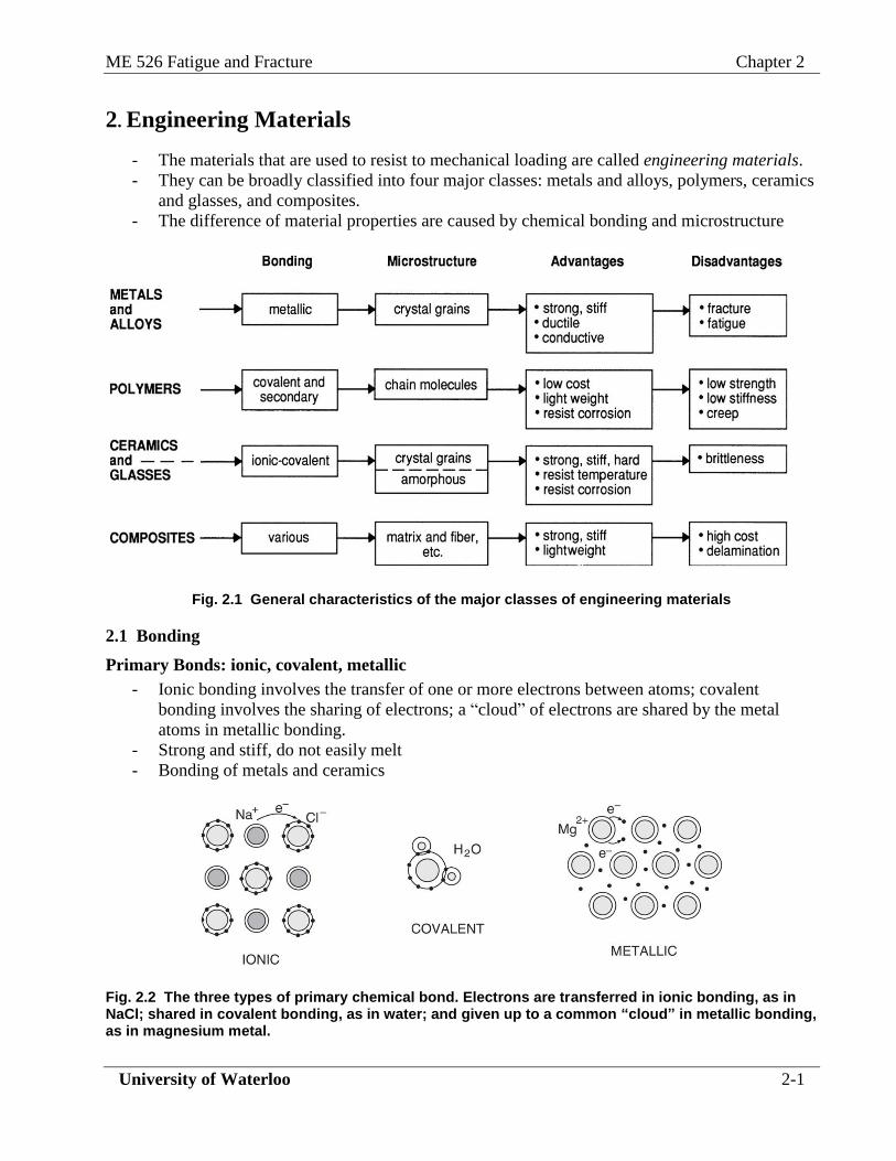
2. Engineering Materials
- The materials that are used to resist to mechanical loading are called engineering materials.
- They can be broadly classified into four major classes: metals and alloys, polymers, ceramics
and glasses, and composites.
- The difference of material properties are caused by chemical bonding and microstructure
Fig. 2.1 General characteristics of the major classes of engineering materials
2.1 Bonding
Primary Bonds: ionic, covalent, metallic
- Ionic bonding involves the transfer of one or more electrons between atoms; covalent
bonding involves the sharing of electrons; a “cloud” of electrons are shared by the metal
atoms in metallic bonding.
- Strong and stiff, do not easily melt
- Bonding of metals and ceramics
Fig. 2.2 The three types of primary chemical bond. Electrons are transferred in ionic bonding, as in NaCl; shared in covalent bonding, as in water; and given up to a common “cloud” in metallic bonding, as in magnesium metal.

ME 526 Fatigue and Fracture Chapter 2
University of Waterloo 2-2
Secondary Bonds: Van der Waals, hydrogen
- Secondary bonds occur due to the presence of an electrostatic dipole, which can be induced
by a primary bond
- Van der Waals bonds arise from the fluctuating positions of electrons relative to an atom’s
nucleus; in water, the side of a hydrogen atom away from the covalent bond to the oxygen
atom has a positive charge, while the exposed portion of the oxygen atom has a negative
charge. The dipoles cause an attraction between adjacent molecules, that is called a hydrogen
bond.
- Relatively weak
(a) (b)
Fig. 2.3 (a) Hydrogen-to-chlorine secondary bonds between chain molecule in polyvinyl chloride; (b) oxygen-to-hydrogen secondary bonds between water molecules.
2.2 Structures
- Metals and ceramics are composed of aggregations of small grains, each of which is an
individual crystal.
- Glasses have an amorphous structure.
- Polymers are composed of chainlike molecules, which are sometimes arranged in regular
arrays in a crystalline manner.
Crystal structure
- The arrangement of atoms in crystals can be described in terms of the smallest grouping,
called unit cell.
- There are seven basic types of unit cell.
Fig. 2.4 The general case of a unit cell in a crystal and three of seven basic types.

ME 526 Fatigue and Fracture Chapter 2
University of Waterloo 2-3
For a given type of unit cell, various arrangements of atoms are possible; each such arrangement is
called a crystal structure.
- PC (primary cubic): rare
- BCC (body centered cubic): a number of common metals (chromium, iron, molybdenum,
tungsten)
- FCC (face centered cubic): common metals (silver, aluminum, lead, copper, and nickel)
- HCP (hexagonal close-packed): beryllium, magnesium, titanium, and zinc
Fig. 2.5 Four crystal structures: PC (Primary Cubic), BCC (Body Centered Cubic), FCC (Face Centered cubic), HCP (Hexagonal close-packed) structures.
- A material may change its crystal structure with temperature or pressure, or with the addition of
alloying elements.
- E.g., the BCC structure of iron (-Fe) changes to FCC (-Fe) above 910C, and back to BCC
(-Fe) above 1390C.
Structures in Polymers
- Amorphous: PMMA (polymethyl methacrylate), PS (polystyrene) and PC (polycarbonate).
- Semicrystalline: PE (polyethylene), PET(polyethylene terephthalate), PTFE (polytetra-
fluoroethylene), PP (polypropylene)
- Crystalline: thermosetting polymers
Fig. 2.6 Amorphous structure (left) and crystalline structure (right) in a polymer
2.3 Metals and Alloys
- Approximately 80% of the one-hundred-plus elements in the periodic table can be classed as
metals.
- A metal alloy is usually a melted-together combination of two or more chemical elements,
where the bulk of the material consists of one or more metals.

ME 526 Fatigue and Fracture Chapter 2
University of Waterloo 2-4
- Iron is the main constituent of the iron-based alloys (steels).
- A wide variety of metallic and nonmetallic chemical elements are used, e.g., boron, carbon,
magnesium, silicon, vanadium, chromium, manganese, nickel, copper, zinc, molybdenum, and tin.
- The amounts and combinations of alloying elements used with various metals have major effects
on their strength, ductility, temperature resistance, corrosion resistance, and other properties.
Table 2.1 Properties and uses for selected engineering metals and their alloys
Irons and Steels
- Iron-based alloys (ferrous alloys, e.g. cast irons and steels) and are the most widely used
structural metals.
- Steels: iron + carbon + manganese + additional alloying elements.
- Pure iron: ingot iron, quite weak
- Cast irons: carbon in excess of 2% and from 1 to 3% silicon.
* Pure iron is quite weak, but is strengthened considerably by the addition of small amounts of
carbon. Additional alloying with small amounts of niobium, vanadium, copper, or other elements
permits strengthening by grain refinement, precipitation, or solid solution effects.
Metal Melting Temp.
Density Elastic
Modulus Typical
Strength Uses; Comments
Tm
°C
(°F)
ρ
g/cm3
(lb/ft3)
E
GPa
(103 ksi)
σu
Mpa
(ksi)
Iron (Fe) and steel
1538 (2800)
7.87 (491)
212 (30.7)
200 to 2500 (30 to 360)
Diverse: structures, machine and vehicle parts, tools. Most widely used engineering metal.
Aluminum (Al)
660 (1220)
2.70 (168)
70 (10.2)
140 to 550 (20 to 80)
Aircraft and other lightweight structure and parts.
Titanium (Ti) 1670
(3040) 4.51 (281)
120 (17.4)
340 to 1200 (50 to 170)
Aircraft structure and engines; industrial machine parts; surgical implants.
Copper (Cu)
1085 (1985)
8.93 (557)
130 (18.8)
170 to 1400 (25 to 200)
Electrical conductors; corrosion-resistant parts, valves, pipes. Alloyed to make bronze and brass.
Magnesium (Mg)
650 (1200)
1.74 (108)
45 (6.5)
170 to 340 (25 to 50)
Parts for high-speed machinery; aerospace parts.
Nickel (Ni)
1455 (2650)
8.90 (556)
210 (30.5)
340 to 1400 (50 to 200)
Jet engine parts; alloying addition for steels.
Cobalt (Co)
1495 (2720)
8.83 (551)
211 (30.6)
650 to 2000 (95 to 300)
Jet engine parts; wear resistant coatings; surgical implants.
Tungsten (W)
3422 (6190)
19.3 (1200)
411 (59.6)
120 to 650 (17 to 94)
Electrodes, light bulb filaments, flywheels, gyroscopes.
Lead (Pb) 328
(620) 11.3 (708)
16 (2.3)
12 to 80 (2 to 12)
Corrosion resistant piping; weights, shot. Alloyed with tin in solders.

ME 526 Fatigue and Fracture Chapter 2
University of Waterloo 2-5
* If sufficient carbon is added for quenching and tempering to be effective, a major increase in
strength is possible.
Table 2.2 Commonly encountered classes of iron and steels
Class Distinguishing Features Typical Uses
Cast iron More than 2% C and 1 to 3% Si Pipes, valves, gears, engine blocks
Plain-carbon
steel
Principal alloying element is carbon
up to 1 %
Structural and machine parts
Low-alloy steel Metallic elements totaling up to 5% High-strength structural and machine parts
Stainless steel At least 10% Cr; does not rust Corrosion resistant piping and nuts and
bolts; turbine blades
Tool steel Heat treatable to high hardness and
wear resistance
Cutters, drill bits, dies
Table 2.3 Some typical irons and steels
Description Identification UNS No.
Principal Alloying Elements, Typical % by Weight
C Cr Mn Mo Ni Si V Other
Ductile cast iron ASTM A395 F32800 3.5 - - - - 2 - -
Low-carbon
steel
AISI 1020 G 10200 0.2 - 0.45 - - 0.2 - -
Medium-carbon
steel
AISI 1045 G 10450 0.45 - 0.75 - - 0.2 - -
High-carbon
steel
AISI 1095 G10950 0.95 - 0.4 - - 0.2 - -
Low-alloy steel AISI 4340 G43400 0.40 0.8 0.7 0.25 1.8 0.2 - -
HSLA steel ASTM A588-A K11430 0.15 0.5 1.1 - - 0.2 0.05 0.3 Cu
Martensitic
stainless steel
AISI 403 S40300 0.15 12 1.0 - 0.6 0.5 - -
Austenitic
stainless steel
AISI 310 S31000 0.25 25 2.0 - 20 1.5 - -
Precipitation
hardening
stainless steel
17-4PH SI 7400 0.07 17 1.0 - 4 1.0 - 4 Cu
0.3 Nb+Ta
Tungsten high-
speed tool steel
AISI T1 T1200I 0.75 3.8 0.25 - 0.2 0.3 1.1 18 W
18 Ni maraging
steel
ASTM A538-C K93I20 0.01 - - 5 18 - - 9 Co, 0.7
Ti

ME 526 Fatigue and Fracture Chapter 2
University of Waterloo 2-6
Naming systems for Irons and Steels
- American Iron and Steel Institute (AISI), the Society of Automotive Engineers (SAE), and the
American Society for Testing and Materials (ASTM International)
- SAE and ASTM have cooperated to develop a new Unified Numbering System (UNS) that
gives designations not only for irons and steels, but also for all other metal alloys.
- The AISI and SAE are nearly identical.
Table 2.4 Summary of the AISI-SAE Designation for Common Carbon and Low-Alloy Steels
Designation Approx. Alloy Content, % Designation Approx. Alloy Content, %
Carbon steels Nickel-molybdenum steels
10XX Plain carbon 46XX Ni 0.85 or 1.82; Mo 0.25
11XX Resulfurized 48XX Ni 3.50; Mo 0.25
12XX Resulfurized and rephosphorized
15XX Mn 1.00 to 1.65 Chromium steels
Manganese steels 50XX(X) Cr 0.27 to 0.65
13XX Mn 1.75 51XX(X) Cr 0.80 to 1.05
52XXX Cr 1.45
Molybdenum steels
Chromium-vanadium steels
40XX Mo 0.25 61XX Cr 0.6 to 0.95; V 0.15
44XX Mo 0.40 or 0.52
Chromium-molybdenum steels Silicon-manganese steels
41XX
Cr 0.50 to 0.95; Mo 0.12 to 0.30
92XX Si 1.40 or 2.00; Mn 0.70 to 0.87; Cr 0 or 0.70
Nickel-chromium-molybdenum steels
Boron steels
43XX Ni 1.82; Cr 0.50 or 0.80; Mo 0.25 YYBXX B 0.0005 to 0.003
47XX Ni 1.45; Cr 0.45; Mo 0.20 or 0.35
81XX Ni 0.30; Cr 0.40; Mo 0.12
86XX Ni 0.55; CrO.50; Mo 0.20
87XX Ni 0.55; Cr 0.50; Mo 0.25
94XX Ni 0.45; Cr 0.40; Mo 0.12

ME 526 Fatigue and Fracture Chapter 2
University of Waterloo 2-7
- The UNS system has a letter followed by a five-digit number. The letter indicates the category
of alloy (e.g., F for cast irons, G for carbon and low-alloy steels, K for various special-purpose
steels, S for stainless steels, and T for tool steels). For carbon and low-alloy steels, the number is
in most cases the same as that used by AISI and SAE, except that a zero is added at the end.
Thus, AISI 1340 is the same steel as UNS G13400.
2.4 Polymers
- Consist of long-chain molecules formed primarily by carbon-to-carbon bonds
- Include plastics, natural and synthetic fibers, rubbers, and cellulose and lignin in wood
- Classified into three groups: thermoplastics, thermosetting plastics, and elastomers.
Table 2.5 Classes, Examples, and Uses of Representative Polymers
Polymer Typical Uses
(a) Thermoplastics: ethylene structure
Polyethylene (PE)
Polyvinyl chloride (PVC)
Polypropylene (PP)
Polystyrene (PS)
Polymethyl methacrylate (PMMA, Plexiglas, acrylic)
Polytetrafluoroethylene (PTFE, Teflon)
Acrylonitrile butadiene styrene (ABS)
Packaging, bottles, piping
Upholstery, tubing, electrical insulation
Hinges, boxes, ropes
Toys, appliance housings, foams
Windows, lenses, clear shields, bone cement
Tubing, bottles, seals
Telephone and appliance housings, toys
(b) Thermoplastics: others
Nylon
Aramids (Kevlar, Nomex)
Polyoxymethylene (POM, acetal)
Polyetheretherketone (PEEK)
Polycarbonate (PC)
Gears, tire cords, tool housings
High-strength fibers
Gears, fan blades, pipe fittings
Coatings, fans, impellers
Safety helmets and lenses
(c) Thermosetting plastics
Phenol formaldehyde (phenolic, Bakelite)
Melamine formaldehyde
Urea formaldehyde
Epoxies
Unsaturated polyesters
Electrical plugs and switches, pot handles
Plastic dishes, tabletops
Buttons, bottle caps, toilet seats
Matrix for composites
Fiberglass resin
(d) Elastomers
Natural rubber; cis-polyisoprene
Styrene-butadiene rubber (SBR)
Polyurethane elastomers
Nitrile rubber Polychloroprene (Neoprene)
Shock absorbers, tires
Tires, hoses, belts
Shoe soles, electrical insulation
O-rings, oil seals, hoses Wet suits, gaskets
- Thermoplastics: soften and melt when heated; then, if cooled, it returns to its original solid
condition.
- Thermosetting plastics do not melt upon reheating, but will instead decompose, as by charring
or burning.
ME 526 Fatigue and Fracture Chapter 2
University of Waterloo 2-8
- Elastomers are capable of rubbery behavior. They can be deformed by large amounts, say 100%
to 200% strain or more, with most of this deformation being recovered after removal of the
stress.
- Names are often abbreviated by acronyms, such as PMMA for polymethyl methacrylate.
- Various trade names and popular names, such as Plexiglas, Teflon, and nylon, are often used in
addition to, or in place of, the chemical names.
- Light weight: around ρ = 1 g/cm3, and few exceed ρ = 2 g/cm
3. (c.f. ρ = 2.7 for Al, ρ ~ 7.9 for
steel).
- Most polymers are relatively weak, with ultimate tensile strengths typically in the range 10 to
200 MPa.
2.5 Ceramics
- Solids that are neither metallic nor organic (carbon-chain based) materials.
- Include clay products, such as porcelain, china, and brick, and also natural stone and concrete.
- Ceramics used in high-stress applications, called engineering ceramics, are often relatively
simple compounds of metals, or the metalloids silicon or boron, with nonmetals such as
oxygen, carbon, or nitrogen.
- Crystalline structure
Advantages
- Highly resistant to corrosion and wear, and melting temperatures are typically quite high.
- These characteristics all arise from the strong covalent or ionic-covalent chemical bonding of
these compounds.
- Stiff (high E) and light in weight.
Disadvantages
- Inherently brittle, because of covalent bonding
- The brittleness is further enhanced by the fact that grain boundaries in these crystalline
compounds are relatively weaker than in metals.
- There are often an appreciable degree of porosity and microscopic cracks. These discontinuities
promote macroscopic cracking and thus also contribute to brittle behavior.
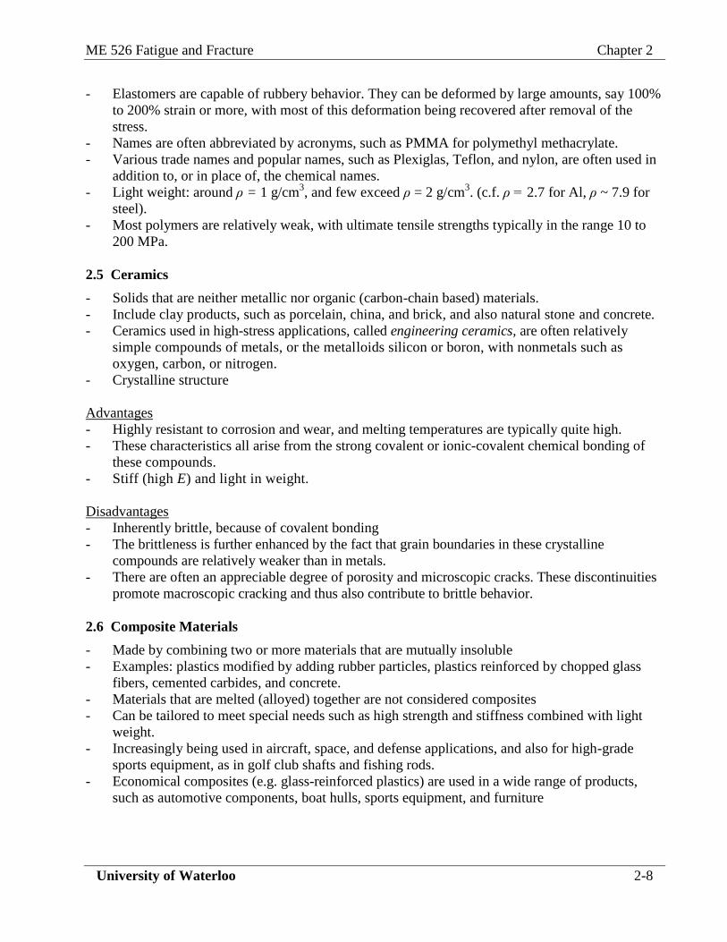
2.6 Composite Materials
- Made by combining two or more materials that are mutually insoluble
- Examples: plastics modified by adding rubber particles, plastics reinforced by chopped glass
fibers, cemented carbides, and concrete.
- Materials that are melted (alloyed) together are not considered composites
- Can be tailored to meet special needs such as high strength and stiffness combined with light
weight.
- Increasingly being used in aircraft, space, and defense applications, and also for high-grade
sports equipment, as in golf club shafts and fishing rods.
- Economical composites (e.g. glass-reinforced plastics) are used in a wide range of products,
such as automotive components, boat hulls, sports equipment, and furniture
ME 526 Fatigue and Fracture Chapter 2
University of Waterloo 2-9
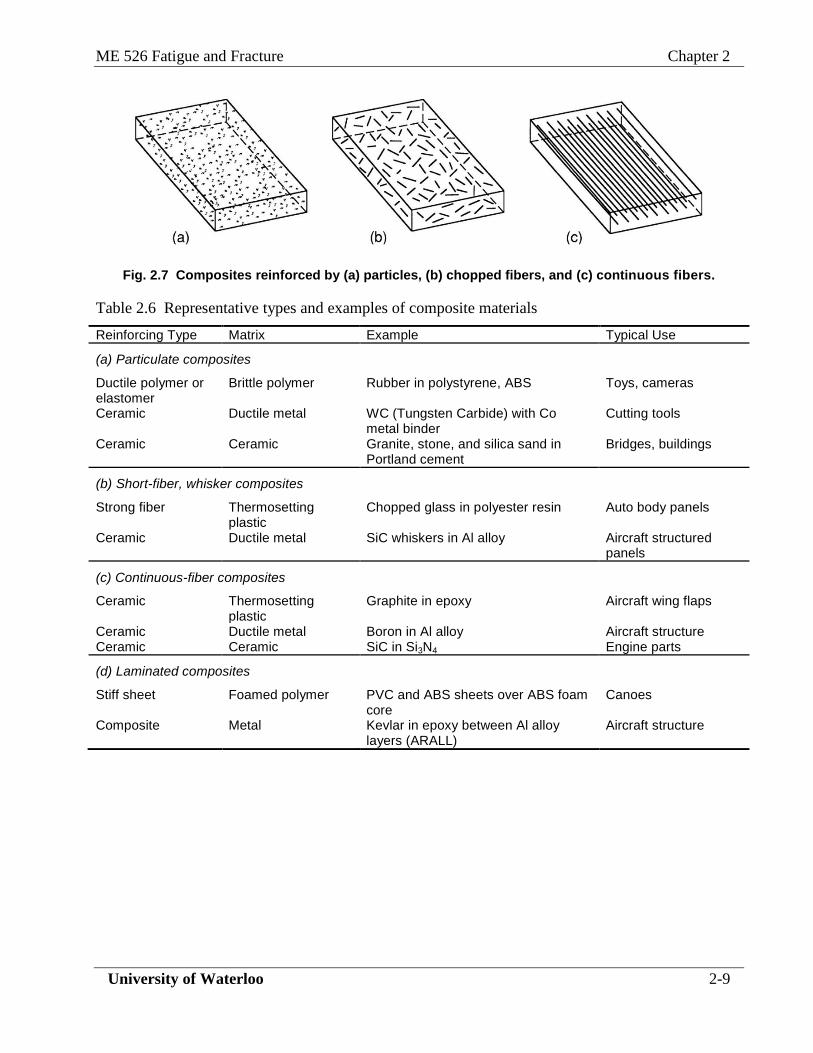
Fig. 2.7 Composites reinforced by (a) particles, (b) chopped fibers, and (c) continuous fibers.
Table 2.6 Representative types and examples of composite materials
Reinforcing Type Matrix Example Typical Use
(a) Particulate composites
Ductile polymer or elastomer
Brittle polymer Rubber in polystyrene, ABS Toys, cameras
Ceramic Ductile metal WC (Tungsten Carbide) with Co metal binder
Cutting tools
Ceramic Ceramic Granite, stone, and silica sand in Portland cement
Bridges, buildings
(b) Short-fiber, whisker composites
Strong fiber Thermosetting plastic
Chopped glass in polyester resin Auto body panels
Ceramic Ductile metal SiC whiskers in Al alloy Aircraft structured panels
(c) Continuous-fiber composites
Ceramic Thermosetting plastic
Graphite in epoxy
Aircraft wing flaps
Ceramic Ductile metal Boron in Al alloy Aircraft structure Ceramic Ceramic SiC in Si3N4 Engine parts
(d) Laminated composites
Stiff sheet Foamed polymer PVC and ABS sheets over ABS foam core
Canoes
Composite Metal
Kevlar in epoxy between Al alloy layers (ARALL)
Aircraft structure

ME 526 Fatigue and Fracture Chapter 2
University of Waterloo 2-10
2.7 Materials Selection
- An engineering component must not deform excessively or fail by fracture or collapse. At the
same time, the cost and often the weight must not be excessive.
- To avoid excessive deformation, deflection due to elastic strain should be limited. For a given
component geometry and applied load, the elastic modulus E of the material is the determining
factor for elastic deformation.
- As to strength, the stress should not exceed the failure strength of the material, such as the yield
strength σ0.
Selection Procedure
1. Classify the variables that enter the problem into categories as follows:
- Requirements
- Geometry that may vary
- Material properties
- Quantity to be minimized or maximized
2. Express the quantity Q to be minimized or maximized as a mathematical function of the
requirements and the material properties, in which the geometry variable does not appear:
)Material()tsRequiremen( 21 ffQ (1.3)
3. Determine Q for each candidate material, and choose the one with smallest or largest value of Q,
depending on the situation.
Case Study: cantilever beam
- Consider the case of a cantilever beam having a circular cross section and a load at the end as in
Fig. 2.8. The length of the beam is fixed, but the radius can be changed to minimize the weight.
Fig. 2.8 Cantilever beam with circular cross-section

ME 526 Fatigue and Fracture Chapter 2
University of Waterloo 2-11
a. Understanding problem:
b. Variables
c. Mathematical expression of m:

ME 526 Fatigue and Fracture Chapter 2
University of Waterloo 2-12
Ex. 2.1
For the beam in Fig. 2.8 and the materials of Table 2.7, proceed as follows:
(a) Perform the materials selection for minimum mass.
(b) Calculate the beam radius r that is required for each material. Assume values of P = 200N,
L=100mm, and X=2.
(c) Extend the analysis to a consideration of cost.
Table 2.7 Selected Typical Materials
Material Type Example Elastic Modulus
E, GPa Strength σc,
MPa
Density
ρ,g/cm3
Relative Cost, Cm
Structural (mild) steel AISI 1020 steel 203 260 7.9 1
Low alloy steel AISI 4340 steel 207 1103 7.9 3
High strength aluminum alloy
7075-T6 Al 71 469 2.7 6
Titanium alloy Ti-6Al-4V 117 1185 4.5 45
Engineering polymer Polycarbonate (PC) 2.4 62 1.2 5
Wood Loblolly pine 12.3 88 0.51 1.5
Economical composite Glass cloth in epoxy (GFRP)
21 380 2.0 10
High-performance composite
Graphite fiber in epoxy laminate (CFRP)
76 930 1.6 200

ME 526 Fatigue and Fracture Chapter 2
University of Waterloo 2-13
Assignment #1
A leaf spring in the suspension system of an experimental vehicle is a beam of length L = 0.5m, with
a rectangular cross section, as shown in Fig. A-1. This part, as currently designed with a low-alloy
steel, has a width t = 60 mm and a depth h = 5 mm. However, if possible, it is desirable to replace
this steel with another material to reduce the weight of the component. To avoid redesigning other
related parts, the t dimension should not be changed, but h can be varied, as long as it does not
exceed 12 mm. The spring stiffness must be k = P/v = 50 kN/m. Also, the spring hits a limit to its
motion at vmax = 30 mm, at which point the stress should not be so large that the safety factor against
material failure is less than X = l.4.
(a) Considering only the k = 50 kN/m requirement, determine which materials in Table 2.7 would
provide a lighter weight component.
(b) For each material, calculate the h necessary to meet the k = 50 kN/m requirement, and also the
safety factor relative to c at vmax = 30 mm. Eliminate any materials that do not meet
h≤12mm and X > 1.4.
(c) Compare the alloy steel design with the use of each of the remaining candidates, considering
cost and any other factors that you believe to be important.
Fig. A-1
Hint:
- zEI
PLv
48
3
max , 12
3thI z →
3
48
L
EI
v
Pk z
- thLm where h can be expressed as the function of other variables.
Related Documents