MD70-X Manual Micro Milling & Drilling System Cameron MD70-X with Flat Panel & Optional Programmable Z Axis User & Technical Manual

Welcome message from author
This document is posted to help you gain knowledge. Please leave a comment to let me know what you think about it! Share it to your friends and learn new things together.
Transcript

MD70-X
Manual Micro Milling & Drilling System
Cameron MD70-X with Flat Panel & Optional Programmable Z Axis
User & Technical Manual
MD70-X Manual Micro Milling & Drilling System – User & Technical Manual
Sept. 2013 Made with pride in the USA Page 2
1. ABOUT THIS MANUAL ................................................................................................................... 3
2. INTRODUCTION ............................................................................................................................... 4
2.1 Overview of the System ................................................................................................................. 4
3. INSTALLATION ................................................................................................................................ 5
3.1 Electrical Requirements .................................................................................................................. 5 3.2 Dimensions ..................................................................................................................................... 5 3.3 Uncrating the System ...................................................................................................................... 5 3.4 Moving the Machine ....................................................................................................................... 6 3.5 Initial Set-up Procedure .................................................................................................................. 7 3.6 Installing the Drill Bit ..................................................................................................................... 7 3.7 Mounting the Work Piece ............................................................................................................... 7
4. OPERATIONAL SET-UP .................................................................................................................. 8
4.1 Safety Precautions .......................................................................................................................... 8 4.2 Reference Diagrams of the MD70-X .............................................................................................. 9 4.3 Operating the Cameron MD70-X Milling & Drilling System .......................................................10 4.4 Video Edge Finder Set-up .............................................................................................................10 4.5 Operating the Programmable Z Axis (Optional) ..........................................................................11
4.5.1 Setting Home Position ...........................................................................................................11 4.5.2 Setting the Offset ...................................................................................................................12 4.5.3 Loading a Program ................................................................................................................12 4.5.4 Creating and Saving a New Program .....................................................................................13 4.5.5 Drilling ..................................................................................................................................14
5. MAINTENANCE ...............................................................................................................................15
5.1 Adjustments ...................................................................................................................................15 5.1.1 Flat Belt Adjustment ..............................................................................................................15 5.1.2 Adjusting the Head Balance Spring .......................................................................................15
5.2 Care and Maintenance ...................................................................................................................15
6. TROUBLESHOOTING .....................................................................................................................16
7. REPLACEMENT PARTS LIST .......................................................................................................18
8. TECHNICAL SERVICE ...................................................................................................................19
9. WARRANTY ......................................................................................................................................20
10. THIRD PARTY DOCUMENTATION .............................................................................................20
11. YOUR NOTES ....................................................................................................................................21

MD70-X Manual Micro Milling & Drilling System – User & Technical Manual
Sept. 2013 Cameron is a Division of Treat Enterprises, Inc. Page 3
1. ABOUT THIS MANUAL
What you will find:
OPERATION
All the information necessary to safely and predictably operate the system is
included. Operators should be familiar with the information in this manual before
operating the system.
INSTALLATION
Detailed installation procedures for the system and its accessories, including
power and space requirements.
SAFETY
The proper and safe operation of this machine, safety tips and concerns.
MAINTENANCE
Maintenance and adjustment sections are included for ease of maintenance and
periodic adjustment scheduling.
TROUBLESHOOTING
The troubleshooting section is limited to simple checks and fixes an operator can
make. Any troubleshooting activities beyond those listed in this section should not
be attempted without input from a Cameron representative.
RECOMMENDED SPARE PARTS
A recommended spare parts list. Stocking these parts at your facility may reduce
downtime.

MD70-X Manual Micro Milling & Drilling System – User & Technical Manual
Sept. 2013 Made with pride in the USA Page 4
2. INTRODUCTION
2.1 Overview of the System
#1Monitor (Flat Panel)
#2Control Box
#3DRO Panel
#41” Travel Dial Indicator
#5VEF Camera
#6X-Y Table
#7Spindle Head Assembly with NSK Spindle
#8Red Lion Programmable Z Axis (Optional)
#1 #2
#3 #4
#5
#6 #7
#8
MD70-X Manual Micro Milling & Drilling System – User & Technical Manual
Sept. 2013 Cameron is a Division of Treat Enterprises, Inc. Page 5
3. INSTALLATION
3.1 Electrical Requirements
The system uses a Nominal 110 VAC, 50-60 HZ @ 5 Amperes. The
power connection is a standard 3-pole male plug, located at the rear of the
control box.
WARNING: DO NOT CONNECT THE POWER CABLE TO ANY POWER SOURCE
UNTIL THE MACHINE IS IN ITS FINAL LOCATION AND ALL OTHER
CONNECTIONS HAVE BEEN MADE.
3.2 Dimensions
Width: 28”
Depth: 28”
Height: 24”
Weight: Approximately 150 lbs.
Be sure to leave space at the rear of the unit for cable routing and access to
rear components. In the interest of safety, we recommend that you allow
for ample free working space surrounding the unit.
The MD70-X is designed and constructed to function in various
manufacturing atmospheres. It is a precisely calibrated piece of
equipment. Please avoid rough handling when moving and installing the
machine.
3.3 Uncrating the System
Due to the ever-changing requirements of our customers and shipping
companies, the crating of the system may differ from shipment to
shipment. A separate set of instructions for unpacking your system is
supplied with the paperwork you received. If you do not find this
paperwork, call Cameron’s customer support.
Rest assured your system has been packaged as safely and reasonably as
possible. We expect the system to be received without damage to it or any
of its parts.
All Cameron equipment is shipped F.O.B. (Freight on Board) Sonora (our
shipping dock).

MD70-X Manual Micro Milling & Drilling System – User & Technical Manual
Sept. 2013 Made with pride in the USA Page 6
If upon receipt of your crate you see that there has been damage, such that
you fear the contents may have been damaged, immediately inform the
shipper. They are responsible for bringing the system safely to you.
Please use caution when uncrating the system. At least two people should
be involved, as one person can not handle the weight and size of the
system.
Here are some simple tips:
Do not tip or jar the equipment.
Do not drop the equipment.
Do not lift the system out of the crate by the X-Y stage handles. Lift
only from the bottom of the plate. (Watch your fingers!)
Do not open the crate in a dusty or moist place.
Inspect the equipment immediately for obvious damage from
shipping.
3.4 Moving the Machine
The MD70-X is separated into modules and can be handled by two people
with average lifting capabilities.
Keep the machine upright and set it down gently on its workbench.
Here are some simple moving tips:
At least two people with average lifting capabilities are required to
move the equipment.
Do not tip or jar the equipment.
Do not drop the equipment.
Do not lift the system by the X-Y stage handles. Lift only from the
bottom plate.
Be sure the table or bench is sturdy enough to hold the machine (150
lbs.).
WARNING: WATCH YOUR FINGERS! WHEN SETTING THE MD70-X DOWN ON
ITS BENCH, MAKE SURE YOU DO NOT SET THE MACHINE ON YOUR FINGERS!
ALTHOUGH THE UNIT IS NOT HEAVY ENOUGH TO CAUSE DAMAGE TO YOU, IT
MAY CAUSE PAIN IF LOWERED ONTO A FINGER OR HAND.
MD70-X Manual Micro Milling & Drilling System – User & Technical Manual
Sept. 2013 Cameron is a Division of Treat Enterprises, Inc. Page 7
3.5 Initial Set-up Procedure
1. Read and understand all manuals and instructions before beginning
set-up.
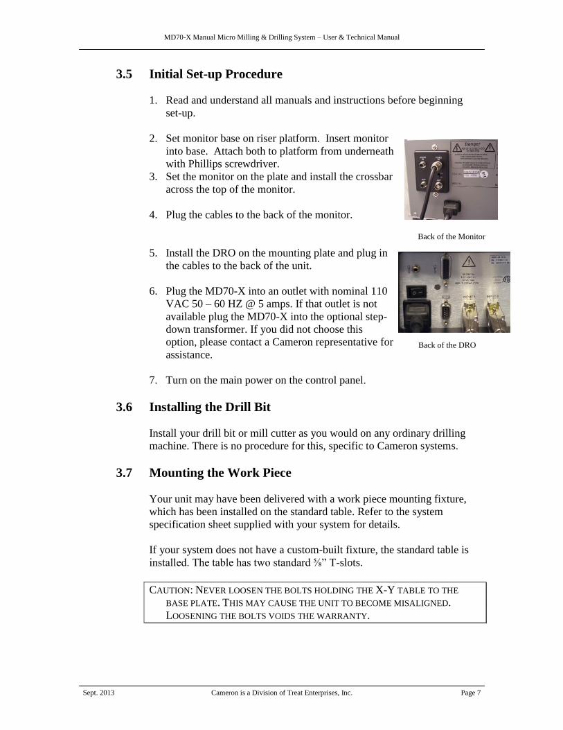
2. Set monitor base on riser platform. Insert monitor
into base. Attach both to platform from underneath
with Phillips screwdriver.
3. Set the monitor on the plate and install the crossbar
across the top of the monitor.
4. Plug the cables to the back of the monitor.
5. Install the DRO on the mounting plate and plug in
the cables to the back of the unit.
6. Plug the MD70-X into an outlet with nominal 110
VAC 50 – 60 HZ @ 5 amps. If that outlet is not
available plug the MD70-X into the optional step-
down transformer. If you did not choose this
option, please contact a Cameron representative for
assistance.
7. Turn on the main power on the control panel.
3.6 Installing the Drill Bit
Install your drill bit or mill cutter as you would on any ordinary drilling
machine. There is no procedure for this, specific to Cameron systems.
3.7 Mounting the Work Piece
Your unit may have been delivered with a work piece mounting fixture,
which has been installed on the standard table. Refer to the system
specification sheet supplied with your system for details.
If your system does not have a custom-built fixture, the standard table is
installed. The table has two standard ⅝” T-slots.
CAUTION: NEVER LOOSEN THE BOLTS HOLDING THE X-Y TABLE TO THE
BASE PLATE. THIS MAY CAUSE THE UNIT TO BECOME MISALIGNED.
LOOSENING THE BOLTS VOIDS THE WARRANTY.
Back of the Monitor
Back of the DRO

MD70-X Manual Micro Milling & Drilling System – User & Technical Manual
Sept. 2013 Made with pride in the USA Page 8
4. OPERATIONAL SET-UP
The following sections explain how to safely set the system up for operation.
4.1 Safety Precautions
The first and most critical step toward the safe and efficient operation of
this or any other piece of equipment is to READ AND UNDERSTAND
ALL SECTIONS OF THIS MANUAL prior to operating the equipment.
It is important to follow all of the safety precautions required by the
machine’s owner as well as state, federal and local codes. In addition to
the rules of common sense, the following safety rules should also be
observed:
Always turn the main power off before connecting or disconnecting
the foot switch. Not doing so could blow the fuse.
Keep extremities, hair, clothing, jewelry or other personal items that
may get caught up in the moving parts of the machine, away from
those parts whenever the machine is running.
Long hair should be tied back while operating or standing close to an
operating machine.
Do not wear loose clothing or dangling jewelry while operating or
standing close to an operating machine.
Do not insert any object, other than the material for which the machine
was constructed to process, into the machine at any point.
The machine must never be operated with the belt cover removed.
Even though machine power is switched off, dangerous voltages are
still present within the control box.
Disconnect the machine from AC power prior to removing any safety
cover.

MD70-X Manual Micro Milling & Drilling System – User & Technical Manual
Sept. 2013 Cameron is a Division of Treat Enterprises, Inc. Page 9
4.2 Reference Diagrams of the MD70-X
Diagram 1: 1.1 Variable Speed Control On/Off
Switch
1.2 Speed Control Knob
1.3 Power Indicator Light
1.4 Fuse Holder
1.5 Main Power Switch
1.6 Video Edge Finder On/Off
Switch and Indicator Light
1.7 White/Black Line Switch
1.8 Crosshair Adjustment Knobs
Diagram 2: 2.1 Upper Oil Cup
2.2 Motor On/Off Switch
2.3 Belt Adjustment Screw
2.4 Lower Oil Cup
2.5 Brush Holder
Diagram 3: 3.1 Foot Switch
3.2 Accessory Outlet
1.1
1.2
1.3
1.4
1.5
1.6
1.8 1.7
2.1
2.2
2.3
2.4
2.5
3.2
3.1

MD70-X Manual Micro Milling & Drilling System – User & Technical Manual
Sept. 2013 Made with pride in the USA Page 10
4.3 Operating the Cameron MD70-X Milling & Drilling System
Steps of operation:
1. Turn on main power switch (1.5 in diagram 1)
2. Turn on the motor (2.2 in diagram 2)
3. To use the variable speed control, turn on the switch (1.1 in diagram
1) and select the desired speed using the control knob (1.2 in
diagram 1)
4. Select tool and proper collet.
5. If you would like to use the VEF, then follow the VEF setup
instructions.
6. Touch tool to part surface and set dial indicator to ‘0’ (To avoid tool
damage we recommend turning the spindle on for this step.)
7. Consult your machinist handbook and the tool manufacturer for
suggested spindle speeds.
We recommend ‘peck drilling’ as the most effective method of drilling
most materials. To extend the life of your drills and end mills, use
cutting fluid when possible. Operation of this machine is most effective
when using the DRO. Please read and follow the instruction manual for
the DRO.
4.4 Video Edge Finder Set-up
The VEF is installed at the factory. The crosshairs can be adjusted at the
discretion of the owner. If you choose to adjust the crosshairs follow the
steps below.
To determine the crosshair to drill differential do the following:
1. Touch drill bit to work piece.
2. Set dial indicator to zero.
3. Drill a test hole and retract to .100 above zero.
4. Lock down column on drill using the column lock, located on the
right side of head, just above the handle.

MD70-X Manual Micro Milling & Drilling System – User & Technical Manual
Sept. 2013 Cameron is a Division of Treat Enterprises, Inc. Page 11
5. Zero the DRO (both X and Y)
6. Dial over the hole in the X-axis (approx. 1.658”)
7. With the column still locked, adjust the camera focus to the surface
of the work piece.
8. Move X-axis over until test hole is centered under the camera.
9. Adjust the Y-axis crosshair line on the enclosure to be in the center
of the hole. This will make the Y differential ‘0’.
10. Record the DRO reading for the X-axis. This is your crosshair
differential.
An optional procedure to steps 2 and 3 above is to set the touch point to
.100”. This allows .100” dial reading before touch point. It also allows the
focus of the camera to be set at zero, giving you a .100” clearance between
the tool and your work piece.
4.5 Operating the Programmable Z Axis (Purchased Option)
4.5.1 Setting Home Position
Home is the height above
the part the drill will return
to when the drill cycle is
finished.
1. Press ‘Set Home/Offset’
button
2. Press F1 to set home
position.
3. Jog up or down to desired home position. Press F3 when
finished.
MD70-X Manual Micro Milling & Drilling System – User & Technical Manual
Sept. 2013 Made with pride in the USA Page 12
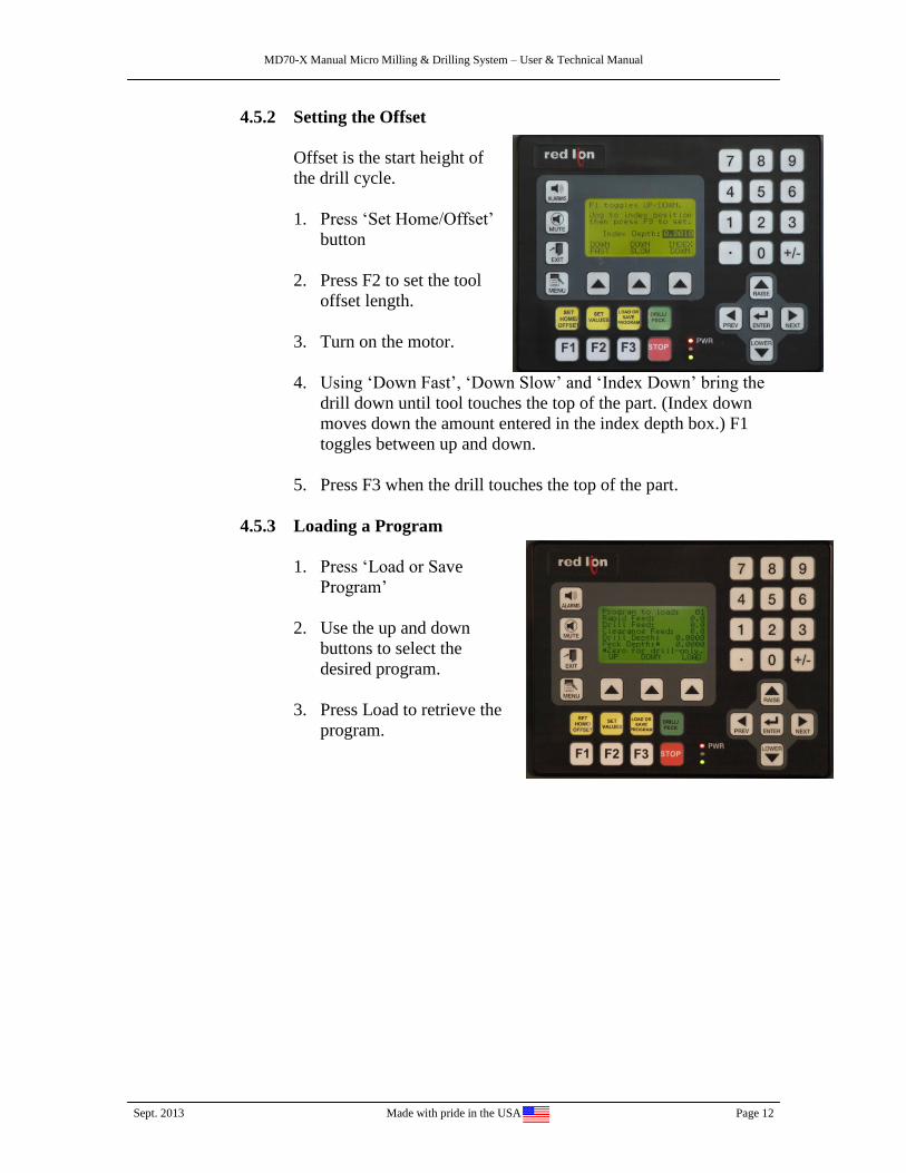
4.5.2 Setting the Offset
Offset is the start height of
the drill cycle.
1. Press ‘Set Home/Offset’
button
2. Press F2 to set the tool
offset length.
3. Turn on the motor.
4. Using ‘Down Fast’, ‘Down Slow’ and ‘Index Down’ bring the
drill down until tool touches the top of the part. (Index down
moves down the amount entered in the index depth box.) F1
toggles between up and down.
5. Press F3 when the drill touches the top of the part.
4.5.3 Loading a Program
1. Press ‘Load or Save
Program’
2. Use the up and down
buttons to select the
desired program.
3. Press Load to retrieve the
program.

MD70-X Manual Micro Milling & Drilling System – User & Technical Manual
Sept. 2013 Cameron is a Division of Treat Enterprises, Inc. Page 13
4.5.4 Creating and Saving a New Program
1. Press ‘Set Values’ to
create a new program.
2. Either use the number pad
or the ‘Raise’ and ‘Lower’
buttons to set the values.
Press ‘Enter’ after
entering the value. Use the
‘Next’ and ‘Previous’
buttons to move to other
values.
Rapid Feed: The downward speed of the drill to the offset
position. And also the upward speed of the drill to the home
position after drill cycle is done.
Drill Feed: The feed rate downward during the drill cycle.
Clearance Feed: The feed rate while the drill cycle is moving
upwards to clear chips from the drill flutes.
Drill Depth: The total depth the hole that is drilled during the
drill cycle.
Peck Depth: The depth drilled before the drill is moved upward
to clear chips from the drill flutes.
3. Press ‘Load or Save Program’ after all values are set.
4. Press F1.
5. Use the up and down buttons to select a program number. Press
Save to save the program under that number. After the program
is saved, press a yellow or green button to continue.

MD70-X Manual Micro Milling & Drilling System – User & Technical Manual
Sept. 2013 Made with pride in the USA Page 14
4.5.5 Drilling
1. After loading a program,
press ‘Drill/Peck’.
2. Press Start to begin
drilling.
3. After drilling cycle is
complete, either move X-
Y table to next hole
location or put in next
part.
4. Press Go Again to repeat drill cycle with the same settings.
5. To stop the drill press
during the drilling cycle,
press the ‘Stop’ button.
Press F1 to return to the
home position. (If you
are at the home position,
it won’t move.)
Use the yellow buttons
to change the settings or
the green button to
restart the drill cycle.

MD70-X Manual Micro Milling & Drilling System – User & Technical Manual
Sept. 2013 Cameron is a Division of Treat Enterprises, Inc. Page 15
5. MAINTENANCE
5.1 Adjustments
5.1.1 Flat Belt Adjustment
If the belt is run too tightly, it will reduce power and cause undue
vibration. Full driving power with maximum smoothness is
attained with proper belt adjustment. To adjust, loosen the belt
adjustment screw (see section 4.2, diagram 2). Retighten screw
after adjusting.
5.1.2 Adjusting the Head Balance Spring
The head balance spring is adjustable to suit particular
requirements by loosening the three screws of the friction lock
ring, located at the left side of the head casting. To adjust the head
balance, turn the friction lock ring one-half turn and turn the spring
tensioner casting with a screwdriver inserted into the slot at the
center of casting. (Counter-clockwise rotation increases spring
tension.)
5.2 Care and Maintenance
Do not over lubricate.
Do not use ‘3 in 1’ oil.
Sliding members should be periodically wiped clean and lubricated
with WD-40.
The two motor bearings should be oiled every 40 hours with a good
quality, non-gumming mineral oil.
The length of the brushes should be checked after approximately 500
hours of use. The brushes should be replaced with factory supplied
brushes if they are less than ¼” in length.
Wipe the monitor with a clean, dry cloth and a mild glass cleaner as
needed. Clean the camera lens with a commercial lens cleaner as
needed.

MD70-X Manual Micro Milling & Drilling System – User & Technical Manual
Sept. 2013 Made with pride in the USA Page 16
6. TROUBLESHOOTING
Usually the first questions that needs to be answered anytime there is a problem
are: “Is it plugged in?” and “Is it turned on?”. These questions may seem ‘dumb’,
but many times the solution arises when these two questions are answered. So,
don’t forget to check if it’s plugged in and turned on.
Problem Things to Check
Machine does not run when main
power switch in turned on
1. Make sure machine is plugged in the
proper power supply.
2. Make sure the motor switch is in the on
position.
3. If the foot switch has been plugged in,
then press down the pedal to activate
for hands free operation.
4. Make sure the variable speed control
knob is not set too low.
5. Make sure the circuit breaker (top right
side of unit) is not tripped.
6. Make sure the 5amp fuse is not blown.
Machine is excessively noisy.
1. Adjust the belt tension.
2. Check and tighten work piece
mounting, vise or fixture.
3. Lightly oil motor with a light mineral
oil.
4. Check for loose pulleys and their
alignment.
Not enough low speed torque.
1. Switch to a smaller pulley on the motor
and/or a larger pulley on the spindle.
2. Check and adjust the belt tension.
Not reaching high RPM settings
1. Check variable speed control knob
position.
2. Check belt position.
3. Check to see that small pulley is
located on spindle and the large pulley
is on the motor.
4. Check the wear length of the motor
brushes, replace if they are less than ¼”
long.
Drill press head will not move up
or down
1. Make sure the column lock is released.
2. Clean column and rack & pinion area
with WD-40. (This should be done after
every 40 hrs of use.)
MD70-X Manual Micro Milling & Drilling System – User & Technical Manual
Sept. 2013 Cameron is a Division of Treat Enterprises, Inc. Page 17
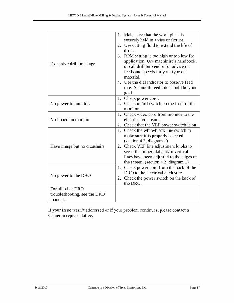
Excessive drill breakage
1. Make sure that the work piece is
securely held in a vise or fixture.
2. Use cutting fluid to extend the life of
drills.
3. RPM setting is too high or too low for
application. Use machinist’s handbook,
or call drill bit vendor for advice on
feeds and speeds for your type of
material.
4. Use the dial indicator to observe feed
rate. A smooth feed rate should be your
goal.
No power to monitor.
1. Check power cord.
2. Check on/off switch on the front of the
monitor.
No image on monitor
1. Check video cord from monitor to the
electrical enclosure.
2. Check that the VEF power switch is on.
Have image but no crosshairs
1. Check the white/black line switch to
make sure it is properly selected.
(section 4.2, diagram 1)
2. Check VEF line adjustment knobs to
see if the horizontal and/or vertical
lines have been adjusted to the edges of
the screen. (section 4.2, diagram 1)
No power to the DRO
1. Check power cord from the back of the
DRO to the electrical enclusure.
2. Check the power switch on the back of
the DRO.
For all other DRO
troubleshooting, see the DRO
manual.
If your issue wasn’t addressed or if your problem continues, please contact a
Cameron representative.

MD70-X Manual Micro Milling & Drilling System – User & Technical Manual
Sept. 2013 Made with pride in the USA Page 18
7. REPLACEMENT PARTS LIST
The following is a partial list of replacement parts. Parts are available from the
factory. Please call for pricing.
Part # Description
MD157-7 Belt Guard $27.50
MD147-1 Single Speed Motor 125.00
MD138-7 Motor Brushes (Set of 2) 10.50
70X-150 Flat Belt 12.00
3AG-5 5amp Fuse
70X-121 Motor Pulley, Standard
70X-122 Motor Pulley, Large
70X-123 Motor Pulley, Small
70X-124 Spindle Pulley, Standard
70X-125 Spindle Pulley, Large
70X-126 Spindle Pulley, Small

MD70-X Manual Micro Milling & Drilling System – User & Technical Manual
Sept. 2013 Cameron is a Division of Treat Enterprises, Inc. Page 19
8. TECHNICAL SERVICE
Cameron MD70-X has been designed and constructed using the highest quality
standards and materials. However, should your unit fail to function properly, in
spite of regular maintenance and you cannot find the solution to the issue in the
troubleshooting section of this manual, then contact Cameron for technical
support. Our engineers can probably determine how to correct the problem on the
phone.
Treat Enterprises, Inc. provides complete after sales service and support for all
Cameron products.
Our hours of operation are:
Monday – Friday 7am to 3:30pm Pacific Standard Time
Cameron observes the following US holidays:
New Year’s Day
Memorial Day
Independence Day
Labor Day
Thanksgiving
Christmas Day
To obtain service, contact Cameron via telephone, fax or email:
Telephone: 1-800-369-7769 or 209-532-7201
Fax: 209-532-1211
Address: Cameron Micro Drill Presses
19401 Rawhide Road, Sonora, CA 95370
Email: [email protected]
Web-site: www.cameronmicrodrillpress.com
MD70-X Manual Micro Milling & Drilling System – User & Technical Manual
Sept. 2013 Made with pride in the USA Page 20
9. WARRANTY
Cameron Micro Drill Presses warrants that items of its own manufacture will be
free from defects in material and/or workmanship at the time of delivery and will
be so for a period of three months after leaving the Cameron facility. If any such
item proves to be defective, Cameron retains the option to repair or replace the
item in question at its own expense. An inspection will take place at the Cameron
facility to determine if the item has been used and maintained as intended during
the warranty period. After contacting Cameron’s service department and receiving
return authorization, the owner of the machine is required to ship the item (freight
prepaid) to Cameron Micro Drill Presses for inspection of the machine.
Warranties on components not manufactured by Cameron, but included and sold
as part of the system, are limited to those provided by their original
manufacturers, However, Cameron will handle returns of those components as
well. The owner must still ship the component prepaid.
This warranty is expressly limited to the repair or replacement of defective items
as described above. In no event shall Cameron be held liable or accountable for
incidental or consequential damage due to any breach of warranty, defect in
material, workmanship or omissions/misstatements in this or any documentation.
Cameron shall not be responsible for repair or replacement of items which have
been subjected to neglect, accident or misuse, or which have been altered by
anyone other than Cameron personnel.
Cameron retains all protected, proprietary rights, including patent rights, rights to
devices originated by Cameron, which are part of the equipment, and rights to
designs or data furnished to the owner.
10. THIRD PARTY DOCUMENTATION
The original manufacturers of components, which are not manufactured by
Cameron, have supplied some information. These are referred to as ‘Third Party
Documentation.’ The information is included in the form in which Cameron
received it with no changes, deletions or additions. Cameron accepts no
responsibility or liability based on the information included in any third party
information. If you believe the information is false or not complete, please contact
the manufacturer of the component.
The third part manuals and/or data sheets either are bound together with this
manual or have been supplied as part of a complete document package typically
delivered with the machine.

MD70-X Manual Micro Milling & Drilling System – User & Technical Manual
Sept. 2013 Cameron is a Division of Treat Enterprises, Inc. Page 21
11. YOUR NOTES
You may use this page to note any changes made, helpful tips, calibration
parameters or set-up information. Use to keep any information not contained in
this manual, which an operator may find useful in the set-up and operation of this
machine.
__________________________________________________________________
__________________________________________________________________
__________________________________________________________________
__________________________________________________________________
__________________________________________________________________
__________________________________________________________________
__________________________________________________________________
__________________________________________________________________
__________________________________________________________________
__________________________________________________________________
__________________________________________________________________
__________________________________________________________________
__________________________________________________________________
__________________________________________________________________
__________________________________________________________________
__________________________________________________________________
__________________________________________________________________
__________________________________________________________________
__________________________________________________________________
Related Documents


