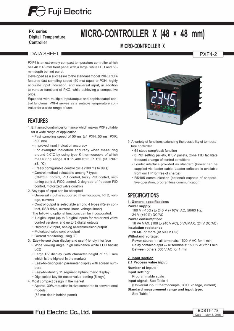
PXF4 is an extremely compact temperature controller which has 48 x 48 mm front panel with a large, white LCD and 58- mm depth behind panel. Developed as a successor to the standard model PXR, PXF4 features fast sampling speed (50 ms) equal to PXH, highly accurate input indication, and universal input, in addition to various functions of PXG, while achieving a competitive price. Equipped with multiple input/output and sophisticated con- trol functions, PXF4 serves as a suitable temperature con- troller for a wide range of use. FEATURES 1. Enhanced control performance which makes PXF suitable for a wide range of application • Fast sampling speed of 50 ms (cf. PXH: 50 ms, PXR: 500 ms) • Improved input indication accuracy For example: indication accuracy when measuring around 0.0°C by using type K thermocouple of which measuring range 0.0 to 400.0°C: ±1.1°C (cf. PXR: ±3.1°C) • Freely configurable control cycle (100 ms to 99 s) • Control method selectable among 7 types (ON/OFF control, PID control, fuzzy PID control, self- tuning control, PID2 control, 2-degrees-of-freedom PID control, motorized valve control) 2. Any type of input can be accepted • Universal input is supported (thermocouple, RTD, volt- age, current) • Control output is selectable among 4 types (Relay con- tact, SSR drive, current linear, voltage linear) The following optional functions can be incorporated: • 1 digital input (up to 3 digital inputs for motorized valve control version), and up to 3 digital outputs • Remote SV input, analog re-transmission output • Motorized valve control output • Current monitoring using CT 3. Easy-to-see clear display and user-friendly interface • Wide viewing angle, high luminance white LED backlit LCD • Large PV display (with character height of 15.3 mm which is the highest in the market) • Easy-to-distinguish parameter display with screen num- bers • Easy-to-identify 11 segment alphanumeric display • Digit select key for easier value-setting (5 keys) 4. Most compact design in the market • Approx. 30% reduction in size compared to conventional models. (58 mm depth behind panel) DATA SHEET PXF4-2 EDS11-178 MICRO-CONTROLLER X (48 × 48 mm) MICRO-CONTROLLER X Date May. 8, 2015 PX series Digital Temperature Controller 5. A variety of functions extending the possibility of tempera- ture controller • 64 steps ramp/soak function • 8 PID setting pallets, 8 SV pallets, zone PID facilitate frequent change of control conditions • Loader interface provided as standard (Power can be supplied via loader cable. Loader software is available from our HP for free of charge) • RS485 communication (optional) capable of coopera- tive operation, programless communication SPECIFICATIONS 1. General specifications Power supply: 100 V (-15%) to 240 V (+10%) AC, 50/60 Hz; 24 V (±10%) DC/AC Power consumption: 10 VA MAX. (100 to 240 V AC), 3 VA MAX. (24 V DC/AC) Insulation resistance: 20 MΩ or more (at 500 V DC) Withstand voltage: Power source ↔ all terminals: 1500 V AC for 1 min Relay contact output ↔ all terminals: 1500 V AC for 1 min Between others 500 V AC for 1 min 2. Input section 2.1 Process value input Number of input: 1 Input setting: Programmable scale Input signal: See Table 1 (Universal input: thermocouple, RTD, voltage, current) Standard measurement range and input type: See Table 1

Welcome message from author
This document is posted to help you gain knowledge. Please leave a comment to let me know what you think about it! Share it to your friends and learn new things together.
Transcript
PXF4 is an extremely compact temperature controller which has 48 x 48 mm front panel with a large, white LCD and 58-mm depth behind panel.Developed as a successor to the standard model PXR, PXF4 features fast sampling speed (50 ms) equal to PXH, highly accurate input indication, and universal input, in addition to various functions of PXG, while achieving a competitive price. Equipped with multiple input/output and sophisticated con-trol functions, PXF4 serves as a suitable temperature con-troller for a wide range of use.
FEATURES 1. Enhanced control performance which makes PXF suitable
for a wide range of application• Fast sampling speed of 50 ms (cf. PXH: 50 ms, PXR:
500 ms)• Improved input indication accuracy For example: indication accuracy when measuring
around 0.0°C by using type K thermocouple of which measuring range 0.0 to 400.0°C: ±1.1°C (cf. PXR: ±3.1°C)
• Freely configurable control cycle (100 ms to 99 s)• Control method selectable among 7 types (ON/OFF control, PID control, fuzzy PID control, self-
tuning control, PID2 control, 2-degrees-of-freedom PID control, motorized valve control)
2. Any type of input can be accepted• Universal input is supported (thermocouple, RTD, volt-
age, current)• Control output is selectable among 4 types (Relay con-
tact, SSR drive, current linear, voltage linear)The following optional functions can be incorporated:• 1 digital input (up to 3 digital inputs for motorized valve
control version), and up to 3 digital outputs• Remote SV input, analog re-transmission output• Motorized valve control output• Current monitoring using CT
3. Easy-to-see clear display and user-friendly interface• Wide viewing angle, high luminance white LED backlit
LCD• Large PV display (with character height of 15.3 mm
which is the highest in the market)• Easy-to-distinguish parameter display with screen num-
bers• Easy-to-identify 11 segment alphanumeric display • Digit select key for easier value-setting (5 keys)
4. Most compact design in the market• Approx. 30% reduction in size compared to conventional
models. (58 mm depth behind panel)
DATA SHEET PXF4-2
EDS11-178
MICRO-CONTROLLER X (48 × 48 mm)MICRO-CONTROLLER X
Date May. 8, 2015
PX seriesDigital Temperature Controller
5. A variety of functions extending the possibility of tempera-ture controller• 64 steps ramp/soak function• 8 PID setting pallets, 8 SV pallets, zone PID facilitate
frequent change of control conditions• Loader interface provided as standard (Power can be
supplied via loader cable. Loader software is available from our HP for free of charge)
• RS485 communication (optional) capable of coopera-tive operation, programless communication
SPECIFICATIONS 1. General specificationsPower supply:
100 V (-15%) to 240 V (+10%) AC, 50/60 Hz; 24 V (±10%) DC/AC
Power consumption: 10 VA MAX. (100 to 240 V AC), 3 VA MAX. (24 V DC/AC)
Insulation resistance:20 MΩ or more (at 500 V DC)
Withstand voltage:Power source ↔ all terminals: 1500 V AC for 1 minRelay contact output ↔ all terminals: 1500 V AC for 1 minBetween others 500 V AC for 1 min
2. Input section2.1 Process value inputNumber of input: 1Input setting:
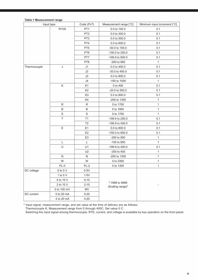
Programmable scaleInput signal: See Table 1
(Universal input: thermocouple, RTD, voltage, current)Standard measurement range and input type:
See Table 1

PXF4-2
2
Indication accuracy (at Ta = 23°C):• Thermocouple input: either ±1°C ±1 digit or ±0.3% ±1
digit of indicated value, whichever is larger*except: Thermocouple B: 0 to 400°C: no accuracy assurance Thermocouple R: 0 to 500°C: ±3°C ±1 digit Thermocouples K, T, E, U, or N: -200 to -100°C: ±2°C ±1 digit• RTD input: ±0.8°C ±1 digit or ±0.2% ±1 digit of indicated
value, whichever is larger• mV input, voltage input, current input: ±0.3%FS ±1 digit
Temperature effect on sensitivity:±0.3%FS/10°C
Indication resolution: See Table 1
Input sampling rate: 50 ms
Input impedance:• Thermocouple, mV input: 1 MΩ or more• Current input: 150 Ω or less (built-in diode)• Voltage input: About 1 MΩ
Variation by signal source resistance:• Thermocouple, mV input: ±0.3%FS ±1 digit per 100 Ω• Voltage input: ±0.3%FS ±1 digit per 500 Ω
Allowable wiring resistance: RTD: 10 Ω or less (per wire)
Allowable input voltage: • DC voltage input: within ±35V• Current input: within ±25 mA• Thermocouple, RTD, mV input: within ±5 V
Noise reduction ratio: • Normal mode: 40 dB (50/60 Hz)• Common mode: 120 dB (50/60 Hz)• Between input and power supply: ±1°C at 220 V AC,
50/60 HzInput correction:
(a) User adjustment: ±50%FS for each of zero and span point
(b) Process value shift: ±10%FS(c) Input filter: 0.0 to 120.0 sec (filter OFF if set at 0.0)(d) Square root extraction: -0.1 to 105% (OFF if set to
-0.1%)Overrange, underrange:
Beyond range of -5 to 105% (accuracy not guaranteed between -5 and 0, and between 100 and 105%FS)*Pt (-200 to 850°C) input: out of the range between -2 to 105%0 to 10 V DC input: out of the range between -2 to 105%Thermocouple E input: out of the range between -5 to 102%
2.2 Remote SV input (optional)Number of inputs:
1Input signal:
Voltage: 0 to 5 V DC /1 to 5 V DC/0 to 10 V DC, Current: 0 to 20 mA DC/4 to 20 mA DC (a 250Ω resistor
is required for current input)Input impedance:
About 1 MΩSampling rate:
50 ms
2.3 Current transformer (CT) input (optional)Input type:
Single phase CT, 1 pointFor 1 A to 30 A: CTL-6-S-HFor 20 A to 100 A: CTL-12-S36-8F
Range of detected current: 1 A to 100 A
Detected current accuracy: Setpoint ±5% FS
Detected current resolution: 0.1 A
ON time necessary for detection: 300 ms MIN.
2.4 Digital input (DI) (optional) Number of points:
Up to 1 (Up to 3 digital inputs for motorized valve control version)
Specifications: No-voltage contact or transistor input
Contact capacity: 5 V DC, about 2 mA (per point)
Input judgment: ON voltage: 2 V DC or lowerOFF voltage: 3 V DC or higher
Sampling pulse width: 50 ms MIN.
Functions: Remote mode selection, SV changeover, control standby, AT startup, timer startup, alarm unlatch, program selec-tion, start/stop/reset, PID switching (normal/reverse), etc.
3. Output section3.1 Control outputNumber of points:
Up to 2 (2 points: Heating/cooling control)Type:
selected among (1) to (6) below(1) Relay contact output (SPST)
• Proportional cycle: 1 to 150 sec• Contact structure: SPST (single pole single throw)• Contact capacity: 250 V AC/30 V DC, 3 A (resistive
load)• Minimum ON/OFF current: 10 mA (5 V DC)• Mechanical life: 20 million operations MIN. (100
operations/min)• Electrical life: 100,000 operations MIN. (rated load)
(2) Relay contact output (SPDT)• Proportional cycle: 1 to 150 seconds• Contact structure: SPDT (single pole double throw)• Contact capacity: 250 V AC/30 V DC, 5 A (resistive
load)• Mechanial life: 50 million operations MIN. (100
operations/min)• Electrical life: 100,000 operations MIN. (rated load)
(3) SSR/SSC drive output• Proportional cycle: 1 to 150 sec• ON voltage: 12 V DC (between 10.7 and 13.2V DC)• OFF voltage: 0.5 V DC or lower• Maximum current: 20 mA DC• Load resistance: 600 Ω MIN.
(4) Current output (0 to 20 mA DC/4 to 20 mA DC)• Accuracy: ±5%FS• Load resistance: 500 Ω MAX.
(5) Voltage output (0 to 5 V DC/1 to 5 V DC/0 to 10 V DC/2 to 10 V DC)• Accuracy: ±5%FS• Load resistance: 10 kΩ MIN.

3
(6) Motorized valve control output• Contact structure: 2 SPST contacts without interlock
circuit *SPST: Single Pole Single Throw• Contact capacity: 250 V AC/30 V DC, 3A (resistive
load)• Mechanical life: 20 million operations MIN. (100
operations/min)• Electrical life: 100,000 operations MIN. (rated load)
3.2 Alam output (optional)Number of outputs:
Relay contact output: Up to 3 (shared common)Up to 2 (independent common)
Output specifications: Relay contact outputContact structure: SPST (single pole single throw)Contact capacity: 250 V AC/30 V DC, 1 A (resistive load)Minimum ON/OFF current: 10 mA (5 V DC)Mechanical life: 20 million operations MIN.
(100 operations/min)Electrical life: 100,000 operations MIN. (rated load)
Output functions: Alarm output (see “Alarm function”), main unit control mode output, program status output, control output 1 and 2, etc.
Output cycle: 100 ms
3.3 Re-transmission output (optional)Number of points:
1Type:
Current/voltage output (0 to 20 mA DC/4 to 20 mA DC/0 to 5 V DC/1 to 5 V DC/ 0 to 10 V DC/2 to 10 V DC)• Guaranteed output range: 0 to 21.0 mA DC/0 to 10.5 V
DC• Accuracy: ±0.2%FS (±5%FS at 1 mA or smaller)• Resolution: 10,000 MIN.• Load resistance: 500 Ω MAX. (current), 10 kΩ MIN.
(voltage)Output cycle:
100 msOutput contents:
PV, SV, DV, MVAdditional function:
Scaling function
4. Indication/setting section4.1 Display unitType:
LCD (with backlight)Indication contents:
Process value indication: 11-segment, 4-digit [white]Setpoint indication: 11-segment, 4-digit [green]Screen No. indication: 7-segment, 3-digit [orange]Indication status: 23 indicator lamps
Luminance setting: possible (4 steps)
4.2 Setting sectionType:
Sheet type keys (with emboss)Number of keys:
5 keys
5. Control functions5.1 Control typesON/OFF controlPID control
• Dual control (heating/cooling)• PID parameters determination: Auto tuning
Fuzzy PID control• Dual control (heating/cooling)• PID parameters determination: Auto tuning
Self tuning controlPID2 control
• Dual control (heating/cooling)• PID parameters determination: Auto tuning
2-degrees-of-freedom PID• PID parameters determination: Auto tuning
Position proportional PID (servo) control without posi-tion feedback
• Full stroke time: 30 seconds MIN.
5.2 Control parameters• Proportional band (P): 0.1 to 999.9%• Integral time (I): 0 to 3200 sec.
Integral time control invalidated when I = 0.
• Differential time (D): 0.0 to 999.9 sec.Differential time control invalidated when D = 0.
• Control cycle: 100 to 900 ms (in 100 ms), 1 to 99 s (in seconds)
• Anti-reset windup: 0 to 100% of measurement range• Hysteresis band: 50% of measurement range (at 2-position control only)• Number of SV and PID combinations: 8 combinations. Changed by any of parameter setting, digital input,
communication, user function keying, zone change.
5.3 Control modeMode type:
Auto, Manual, Remote* During 2-position control in Manual mode, 2-position
manual operation with MV = 100% or 0% is operated.Mode switching:
• Auto↔Manual: Balanceless·bumpless• Auto/Manual → Remote: Balance·bumpless• Auto/Manual ← Remote: Balance·bumpless
6. Alarm function6.1 Number of alarm setting points
3 points
6.2 Alarm typeProcess value (upper limit/lower limit, absolute/deviation, range), main unit error, etc.(non-excitation, delay, latch, timer function option pro-vided)
6.3 Heater current alarm function (optional)*Current detector (CT) is to be prepared separately (see page 7.)Detectable range:
1 A to 100 ADetected current resolution:
0.1 ASetting resolution:
0.1 AHysteresis:
0.0 A to 100.0 A

PXF4-2
4
7. Communication function7.1 RS-485 interface (optional)Number of points:
1 pointPhysical specifications:
EIA-485Protocol:
Modbus-RTUCommunication method:
Half duplex bit serial, Asynchronous communicationCode type:
Data length: 8 data bits. Parity: Odd, even, none.Communication rate:
9600 bps, 19200 bps, 38.4 kbps, 115.2 kbpsConnection status:
Up to 32 units connectable including multidrop master function
Communication distance: Up to 500 m (total connect extension)
Additional functions:• Cooperative operation
The function in which several temperature controllers (as slave devices) can be operated by a master tem-perature controller.
• Programless communicationThe function in which a temperature controller can com-municate with a PLC without program.Supported PLCs: Mitsubishi PLC Q series
Siemens PLC S7 series
8. Processing at power failureMemory protection: Protect by non-volatile memory
9. Self-diagnosisMethod: Program error supervision by watchdog timer
10. Operation and storage conditionsOperating ambient temperature:
-10 to 50°CStorage temperature:
-20 to 60°COperating/storage ambient humidity:
90%RH MAX. (no condensing)Warm-up time:
30 min MINVibration:
During transportation 9.8 m/s2 (1G) or less Impact:
During transportation: 294 m/s2 (30G) or less
11. StructureMounting method:
Panel mountExternal terminals:
Screw terminals, M3Case: material:
• ABS, PPO• Non-combustibility grade: UL94V-0 equivalent• Color: Black
Protection structure: • Panel front side: IP66, NEMA-4X equivalent (When the panel is mounted using our genuine packing.
Not water-proof if mounted closely together.)• Body: IP20 equivalent (slits on top and bottom)• Terminals: IP00 equivalent. Terminal cover can be
mounted optionally.
Dimensions: 48 (W) × 48 (H) × 58 (D) mm
Weight: approx. 100g
12. User customize function12.1 Program (ramp/soak) functionNumber of program steps:
64 steps x 1 pattern,32 steps x 2 pattern,16 steps x 4 pattern8 steps x 8 pattern(1 step = 2 segments)
Control option: Operation control by digital inputStatus output by digital output
Basic functions:(1) Segment time can be set in “Hour, Minutes” or “Min-
utes, Seconds”(2) Guarantee soak(3) Repeat action(4) PV start(5) Delay start(6) Power restoring function
Memory backup: EEPROM
12.2 User functionsPressing the user key can perform Auto/Manual change, Standby ON/OFF change, local SV/remote SV change, ramp/soak change or other functions as assigned.
12.3 Password function3-level password function
13. Simple power-monitoring function and operating days alarm
13.1 Simple power-monitoring function• By connecting a current transformer (to be prepared
separately), electric power consumption of a heater can be displayed.
(Electric power is calculated with the fixed voltage value.)• Current detector (CT) is to be prepared separately (see
page 7.)• Current detection range: 1 A to 100 A
13.2 Operating days alarm• Displays the operating days and activates alarm output
(optional) when it exceeds the setpoint.• This function is useful for preventive maintenance
because it let you know the appropriate time for main-tenance work.
5
Table 1 Measurement rangeInput type Code (PvT) Measurement range [°C] Minimum input increment [°C]
Pt100 PT1 0.0 to 150.0 0.1
PT2 0.0 to 300.0 0.1
PT3 0.0 to 500.0 0.1
PT4 0.0 to 600.0 0.1
PT5 -50.0 to 100.0 0.1
PT6 -100.0 to 200.0 0.1
PT7 -199.9 to 600.0 0.1
PT8 -200 to 850 1
Thermocouple J J1 0.0 to 400.0 0.1
J2 -20.0 to 400.0 0.1
J3 0.0 to 800.0 0.1
J4 -100 to 1000 1
K K1 0 to 400 0.1
K2 -20.0 to 500.0 0.1
K3 0.0 to 800.0 0.1
K4 -200 to 1300 1
R R 0 to 1700 1
B B 0 to 1800 1
S S 0 to 1700 1
T T1 -199.9 to 200.0 0.1
T2 -199.9 to 400.0 0.1
E E1 0.0 to 800.0 0.1
E2 -150.0 to 800.0 0.1
E3 -200 to 800 1
L L -100 to 850 1
U U1 -199.9 to 400.0 0.1
U2 -200 to 400 1
N N -200 to 1300 1
W W 0 to 2300 1
PL-II PL-2 0 to 1300 1
DC voltage 0 to 5 V 0-5V
"-1999 to 9999 (Scaling range)"
-
1 to 5 V 1-5V
0 to 10 V 0-10
2 to 10 V 2-10
0 to 100 mV MV
DC current 0 to 20 mA 0-20
4 to 20 mA 4-20
* Input signal, measurement range, and set value at the time of delivery are as follows: Thermocouple K, Measurement range from 0 through 400C, Set value 0 C. Switching the input signal among thermocouple, RTD, current, and voltage is available by key operation on the front panel.

PXF4-2
6
CODE SYMBOLS
SCOPE OF DELIVERY• Controller × 1• Instruction manual × 1• Panel mounting frame × 1• Watertight packing × 1
Specifications
4 5 6 7 8PXF
4
56
7
89
10
11
1213
4
4 A 0 02 -
A
ABCEP
YACEPRS
2
01FMJ
NYVWCABD
<Front panel size W × H>48 × 48mm–<Control output 1>Relay contact (SPST)Relay contact (SPDT)SSR drive outputCurrent outputVoltage output<Control output 2>NoneRelay contact (SPST)SSR drive outputCurrent outputVoltage outputRe-transmission output (current)Re-transmission output (voltage)<Revision code><Alarm output>None1 point2 points3 points2 points (independent common)<Power supply voltage/instruction manual>100 to 240 V AC, no instruction manual100 to 240 V AC, Japanese & English100 to 240 V AC, English100 to 240 V AC, Chinese & English24 V AC/DC, no instruction manual24 V AC/DC, Japanese & English24 V AC/DC, English24 V AC/DC, Chinese & English<Option>NoneRE-485 CommunicationDigital input (DI1)RS-485 communication + Digital input (DI1)RS-485 communication + Remote SV input RE-485 Communication + CT input–
9 10 11 12 13
Digit Note
Note1Note1
Note3Note2
YMSVKJ
0 0
<48 x 48mm size>Standard type
Note 1: Not available for the 7th code "C", "E", "P", "R", "S". However, if you want to order the 6th code "A" (SPST relay contact for the control output 1) and the 7th code "R" or "S" (current/voltage re-transmission output for the control output 2), specify the model as follows:
Note 2: When using the CT input as a heater burnout alarm, add one alarm output for it in the 9th code.Note 3: When using the current input for the remote SV input, add a 250-ohm resistor to the input terminal.
PXF4AA 2- 02RS

7
OPTIONAL ITEMSInstruction manual for RS-485 communication function (MODBUS) Type: INP-TN5A2227
Current detector (CT) 1 to 30 A Type: ZOZ*CCTL-6-S-H
20 to 100 A Type: ZOZ*CCTL-12-S36-8
Terminal cover Type: ZZPPXR1-A230
Parameter loader interface cable Type: ZZP*TQ501923C3
Shunt resistor (250Ω ± 0.1%) Type: ZZPPXR1-A190
Specifications
4 5 6 7 8PXF
4
56
7
89
10
11
1213
4
4 A T Y 0 02 -
A
T
Y2
01FJ
NYVWCABD
<Front panel size W × H>48 × 48mm–<Control output 1>Motorized valve control output<Control output 2>None<Revision code><Alarm output>None1 point2 points2 points (independent common)<Power supply voltage/instruction manual>100 to 240 V AC, no instruction manual100 to 240 V AC, Japanese & English100 to 240 V AC, English 100 to 240 V AC, Chinese & English 24 V AC/DC, no instruction manual24 V AC/DC, Japanese & English 24 V AC/DC, English24 V AC/DC, Chinese & English <Option>NoneDigital input (DI 1, 2, 3) RS-485 communication + Digital input (DI1)–
9 10 11 12 13
Digit Note
YDV
0 0
<48 x 48mm size>Motorized valve control type
Current detector (CT)
• Specification : 1 to 30 A • Specification : 20 to 100 A
15
7.5
30
40
M3,depth 4
409
30
10
257
2.510.5
3040
2.8
21
15
ø5.8
ø3.5
ø12
ø2.36
Note 1) Detection is available only for single phase heater.Note 2) Unusable for heater control by thyristor phase angle control.

PXF4-2
8
Panel mounting adapter for replacement from PXR7 to PXF4 (Type: ZZP*TQ502732C1)
Outline diagram
Mounting bracket
When panel thickness is 8 mm
Mounting screw(for 4 points)
Watertight packing
Panel (1 to 8 mm)
PXF4
Mounting frame(provided with PXF4)
How to install PXF4 with the adapter

9
OUTLINE DIAGRAM (Unit : mm)
48
48
7.7 58
1 Mounting frame
t (panel thickness) 1 ≤ t ≤ 8
Panel
Waterproof packingTerminal cover (option)
48 (T
erm
inal
cov
er)
44.8 57
13-187-121-6
Rear view
63 MIN.
73 M
IN.
Terminal block is not attached to unused terminals (terminal 7 to 12) according to the model.
Terminal screw M3
6.2
Side stick mounting (n units)
45+0
.5 0
(48×n-3) +0.50
Waterproof is not available in stick mounting.
45+0.5 0
45+0
.5 0
73.2 ((If with terminal cover)
PANEL CUTOUT SIZE (Unit : mm)
PXF4-2
10
5
4
6
2
3
1
11
10
12
8
9
7
17
16
18
14
15
13
100-240VAC
+
–A
BB
+
–
+
–
Alarm output
Option
4
3
2
1
4
3
2
1
4
3
2
1AL1
AL2AL2 COM
AL1 COMAL1
AL3COM
AL2AL1
AL2COM
Non-C
24VAC/24VDC
50/60Hz 50/60Hz
+
–
DI1
DI-COMCT1RSV1
+
–RS485
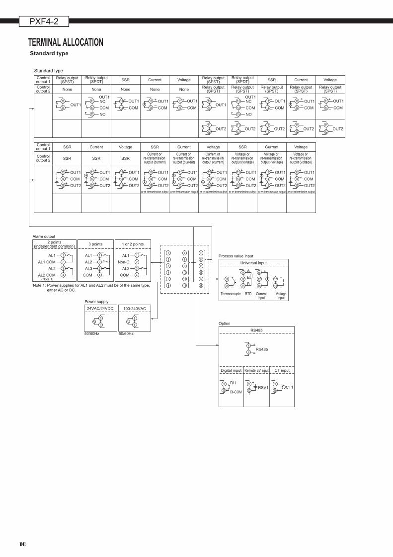
Note 1: Power supplies for AL1 and AL2 must be of the same type, either AC or DC.
Standard type
14
13
14
13
15 NOCOMNC
OUT114
13
–
+
COM
OUT1
SSR SSR
14
13
+
OUT1COM
–
14
13
–
+
COM
OUT1
12
11
14
13OUT1
OUT212
11OUT2
14
13
15 NOCOMNCOUT1
12
11OUT2
–
+
COM
OUT1
12
11OUT2
14
13
14
13
+
OUT1COM
–
12
11OUT2
14
13
–
+
COM
OUT1
14
13
15
14
13
15
14
13
15
14
13
15
14
13
15
14
13
15
14
13
15
14
13
15
14
13
15OUT2COMOUT1–
+
+
OUT2COMOUT1–
+
+
OUT2COMOUT1–
+
+
OUT2COMOUT1–
+
+
OUT2COMOUT1–
+
+
OUT2COMOUT1–
+
+
OUT2COMOUT1–
+
+
OUT2COMOUT1–
+
+
OUT2COMOUT1–
+
+
OUT1
SSR SSR SSR
SSR SSRSSR
17
16
18
17
16
18
17
18
17
18
6
5
6
5
6
5
10
9
10
9
10
9
Controloutput 1Controloutput 2
Controloutput 1
Controloutput 2
Relay output(SPST)
Relay output(SPDT)
None None None None None
VoltageCurrent Relay output(SPST)
Relay output(SPST)
Relay output(SPST)
Relay output(SPST)
Relay output(SPST)
Relay output(SPST)
Relay output(SPDT) VoltageCurrent
VoltageCurrent VoltageCurrent VoltageCurrent
or re-transmission output or re-transmission output or re-transmission output or re-transmission output or re-transmission output or re-transmission output
Current or re-transmission output (current)
Current or re-transmission output (current)
Current or re-transmission output (current)
Voltage or re-transmission output (voltage)
Voltage or re-transmission output (voltage)
Voltage or re-transmission output (voltage)
1 or 2 points3 points
(Note 1)
2 points(independent common)
Power supply
Process value input
Universal input
RTD Currentinput
Voltageinput
Thermocouple
Remote SV inputDigital input CT input
RS485
TERMINAL ALLOCATIONStandard type
11
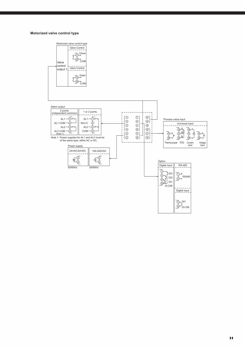
Motorized valve control type
Power supply
Open
COM
Close
24VAC/24VDC
Note 1: Power supplies for AL1 and AL2 must be of the same type, either AC or DC.
COM
+
–
A
BB
+
–
+
–
17
16
18
17
16
18
17
18
17
18
5
4
6
2
3
1
11
10
12
8
9
7
17
16
18
14
15
13
100-240VAC
50/60Hz 50/60Hz
6
5
6
5
1 or 2 points2 points(independent common)
4
3
2
1
4
3
2
1AL1
AL2AL2 COM
AL1 COM
AL1
AL2COM
Non-C
(Note 1)
DI1
DI-COM
+
–RS4858
7
10
9
12
11
14
13
8
7
10
9
DI3DI2
DI1DI-COM
Valvecontroloutput 1
Valve Control
Valve Control
Motorized valve control type
Alarm output
RTD Currentinput
Voltageinput
Thermocouple
Universal input
Process value input
Option
Digital input RS-485
Digital input

PXF4-2
Printed in Japan
Caution on Safety
*Before using this product, be sure to read its instruction manual in advance.
Information in this catalog is subject to change without notice.
Grobal Sales SectionInstrumentation & Sensors Planning Dept.1, Fuji-machi, Hino-city, Tokyo 191-8502, Japanhttp://www.fujielectric.comPhone: +81-42-514-8930 Fax: +81-42-583-8275http://www.fujielectric.com/products/instruments/
INSULATION BLOCk DIAGRAM
Power Internal circuit
Control output 1 (relay contact)or
Motorized valve OPEN output
Alarm output 1 (relay contact)Alarm output 1 to 3
(relay contact)Alarm output 2 (relay contact)
Control output 2 (relay contact)or
Motorized valve CLOSE output
Process value input
• When the 9th code is "J" AL 1 and 2: independent common
: Basic insulation: Functional insulation: No insulation
Digital input 1 to 3
Communication (RS-485)
• When the 9th code is other than "J" AL 1 to 3: shared common
Remote SV input
CT input
Control output 1 (SSR drive, current, voltage)
Control output 2 (SSR drive, current, voltage)
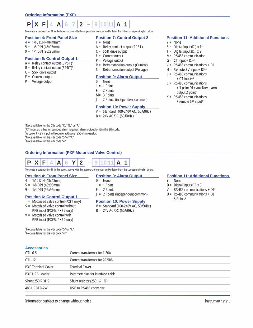
Ordering Information (PXF)
Position 4: Front Panel Size4 = 1/16 DIN (48x48mm) 5 = 1/8 DIN (48x96mm) 9 = 1/4 DIN (96x96mm)
Position 6: Control Output 1A = Relay contact output (SPST)1 B = Relay contact output (SPDT)1 C = SSR drive output E = Current output P = Voltage output
Position 7: Control Output 2Y = None A = Relay contact output (SPST) C = SSR drive output E = Current output P = Voltage output R = Retransmission output (Current) S = Retransmission output (Voltage)
Position 9: Alarm Output0 = None 1 = 1 Point F = 2 Points M = 3 Points J = 2 Points (independent common)
Position 10: Power SupplyV = Standard (100-240V AC, 50/60Hz) B = 24V AC/DC (50/60Hz)
Position 11: Additional FunctionsY = None S = Digital Input (DI) x 14 T = Digital Input (DI) x 25
M = RS485 communication G = CT input + DI2,5
V = RS485 communications + DI H = Remote SV input + DI3,5
J = RS485 communications + CT input2,4
C = RS485 communications + 3 point DI + auxiliary alarm output 2 point5
K = RS485 communications + remote SV input3,4
PTo create a part number fi ll in the boxes above with the appropriate number and/or letter from the corresponding list below.
X F 4 A 6 7 2 – 9 10 11 A 1
1 Not available for the 7th code “C,” “E,” or “P.”2 CT input as a heater burnout alarm requires alarm output for it in the 9th code.3A current RSV input will require additional 250ohm resistor.4Not available for the 4th code “5” or “9.”5 Not available for the 4th code “4.”
Information subject to change without notice. Instrumart 121216
Ordering Information (PXF Motorized Valve Control)
Position 4: Front Panel Size4 = 1/16 DIN (48x48mm) 5 = 1/8 DIN (48x96mm) 9 = 1/4 DIN (96x96mm)
Position 6: Control Output 1T = Motorized valve control (PXF4 only) S = Motorized valve control without
PFB input (PXF5, PXF9 only) V = Motorized valve control with
PFB input (PXF5, PXF9 only)
Position 9: Alarm Output0 = None 1 = 1 Point F = 2 Points J = 2 Points (independent common)
Position 10: Power SupplyV = Standard (100-240V AC, 50/60Hz) B = 24V AC/DC (50/60Hz)
Position 11: Additional FunctionsY = None D = Digital Input (DI) x 31 V = RS485 communications + DI1
U = RS485 communications + DI 3 Points2
PTo create a part number fi ll in the boxes above with the appropriate number and/or letter from the corresponding list below.
X F 4 A 6 Y 2 – 9 10 11 A 1
1Not available for the 4th code “5” or “9.”2 Not available for the 4th code “4.”
AccessoriesCTL-6-S Current transformer for 1-30A
CTL-12 Current transformer for 20-50A
PXF Terminal Cover Terminal Cover
PXF USB Loader Parameter loader interface cable
Shunt 250 ROHS Shunt resistor (250 +/- 1%)
485 USBTB-2W USB to RS485 converter
Related Documents