August 4, 2000 Manual no. 10657-301-0300 Matrox 4Sight User Guide

Welcome message from author
This document is posted to help you gain knowledge. Please leave a comment to let me know what you think about it! Share it to your friends and learn new things together.
Transcript

August 4, 2000
Manual no. 10657-301-0300
Matrox 4Sight
User Guide

Matrox® is a registered trademark of Matrox Electronic Systems Ltd.
MS-DOS®, Windows®, Windows NT®, Windows 98®, Windows NT Embedded®, and Windows CE® are registered trademarks of Microsoft Corporation.
Embedded DOS is a trademark of General Software, Inc.
DiskOnChip® is a registered trademark of M-Systems.
PC/104™ and PC/104-Plus™ are trademarks of the PC/104 Consortium.
Intel® is a registered trademark of Intel Corporation.
Davicom is a trademark of Davicom Semiconductor, Inc.
National Semiconductor® Geode™ GXLV is a registered trademark of National Semiconductor Corporation.
All other nationally and internationally recognized trademarks and tradenames are hereby acknowledged.
© Copyright Matrox Electronic Systems Ltd., 2000. All rights reserved.
Disclaimer: Matrox Electronic Systems Ltd. reserves the right to make changes in specifications at any time and without notice. The information provided by this document is believed to be accurate and reliable. However, no responsibility is assumed by Matrox Electronic Systems Ltd. for its use; nor for any infringements of patents or other rights of third parties resulting from its use. No license is granted under any patents or patent rights of Matrox Electronic Systems Ltd.
PRINTED IN CANADA

Contents
Using this manual . . . . . . . . . . . . . . . . . . . . . . . . . . . . . . . . . . . . . . 13
Chapter 1: Before you begin. . . . . . . . . . . . . . . . . . . . . . . . . . . . . 15
Matrox 4Sight overview . . . . . . . . . . . . . . . . . . . . . . . . .16
Software overview . . . . . . . . . . . . . . . . . . . . . . . . . . . . .20
Matrox 4Sight CD . . . . . . . . . . . . . . . . . . . . . . . . . . . . .22
Inspecting your Matrox 4Sight package . . . . . . . . . . . . .24
Standard items . . . . . . . . . . . . . . . . . . . . . . . . . . . . .24
Optional items . . . . . . . . . . . . . . . . . . . . . . . . . . . . .24
Handling precautions . . . . . . . . . . . . . . . . . . . . . . . . . .25
Part 1: Using the integrated unit
Chapter 2: Connecting and configuring external peripherals to the unit . . . . . . . . . . . . . . . . . . . . . . . . . . . . . . . . . . 29
Before you begin . . . . . . . . . . . . . . . . . . . . . . . . . . . . . .30
Configuring external devices under
Windows NT Embedded . . . . . . . . . . . . . . . . . . . . . . . . .31
Mouse and keyboard . . . . . . . . . . . . . . . . . . . . . . . . . . .31
VGA display monitor . . . . . . . . . . . . . . . . . . . . . . . . . . .32
LAN options. . . . . . . . . . . . . . . . . . . . . . . . . . . . . . . . . .33
Printing devices. . . . . . . . . . . . . . . . . . . . . . . . . . . . . . .37
Video Input devices . . . . . . . . . . . . . . . . . . . . . . . . . . . .37
IEEE 1394 ports . . . . . . . . . . . . . . . . . . . . . . . . . . . . . .39
Serial or parallel interface . . . . . . . . . . . . . . . . . . . . . . .40
Auxiliary I/Os on the Matrox 4Sight . . . . . . . . . . . . . . .40
NTSC/PAL/RGB video output device . . . . . . . . . . . . . . .41
Stereo audio device . . . . . . . . . . . . . . . . . . . . . . . . . . . .41
Chapter 3: Managing the Matrox 4Sight under Windows NT Embedded . . . . . . . . . . . . . . . . . . . . . . . . . . . . . . . . . 43
Windows NT Embedded . . . . . . . . . . . . . . . . . . . . . . . . .44
Using Windows NT Embedded command prompt . . . . . .45
NTConfig: Basic configuration utility . . . . . . . . . . . . . . .46
Adding or modifying user accounts
on Matrox 4Sight. . . . . . . . . . . . . . . . . . . . . . . . . . . . . .47
Setting environment variables . . . . . . . . . . . . . . . . . . . .48
Setting the multi-boot option. . . . . . . . . . . . . . . . . . . . .49
Sharing and connecting to remote directories . . . . . . . .49
Other useful remote commands . . . . . . . . . . . . . . . .51
Backing up your DiskOnChip image . . . . . . . . . . . . . . .51
Logging off or shutting down Matrox 4Sight. . . . . . . . . .52
Guidelines for setting up remote management
of the Matrox 4Sight unit . . . . . . . . . . . . . . . . . . . . . . .52
Chapter 4: Developing an application for Matrox 4Sight under Windows NT Embedded . . . . . . . . . . . . . . .53
Application development . . . . . . . . . . . . . . . . . . . . . . . .54
Installing a MIL application . . . . . . . . . . . . . . . . . . . . . .55
Installing an ActiveMIL/ActiveMIL-Lite application. . . . .57
Remote debugging on Matrox 4Sight using
Microsoft Visual C++ 6.0 . . . . . . . . . . . . . . . . . . . . . . . .58
Debugging. . . . . . . . . . . . . . . . . . . . . . . . . . . . . . . . .59
Remote debugging on Matrox 4Sight using
Microsoft Visual Basic . . . . . . . . . . . . . . . . . . . . . . . . . .61
Working with MIL . . . . . . . . . . . . . . . . . . . . . . . . . . . . .61
Automatically launching applications . . . . . . . . . . . . . .62
Removing unnecessary files from Matrox 4Sight . . . . . .63
Chapter 5: Managing the DiskOnChip . . . . . . . . . . . . . . . . . . . .65
DiskOnChip . . . . . . . . . . . . . . . . . . . . . . . . . . . . . . . . .66
BIOS Setup . . . . . . . . . . . . . . . . . . . . . . . . . . . . . . . .66
Replacing the DiskOnChip. . . . . . . . . . . . . . . . . . . . . . .67
Reinstalling the DiskOnChip image
on your DiskOnChip . . . . . . . . . . . . . . . . . . . . . . . . . . .68
Formatting the DiskOnChip . . . . . . . . . . . . . . . . . . .69
Building your own
Windows NT Embedded configuration . . . . . . . . . . . . . .69
Part 2: Making hardware, driver, and OS modifications
Chapter 6: Using the hard drive based Matrox 4Sight. . . . . . . . 73
Introduction . . . . . . . . . . . . . . . . . . . . . . . . . . . . . . . . .74
Removing the Matrox 4Sight chassis . . . . . . . . . . . . . . .75
Connecting to a floppy drive . . . . . . . . . . . . . . . . . . . . .76
Connecting IDE devices . . . . . . . . . . . . . . . . . . . . . . . . .77
Installing a full Windows NT Workstation
on Matrox 4Sight. . . . . . . . . . . . . . . . . . . . . . . . . . . . . .78
Installing device drivers . . . . . . . . . . . . . . . . . . . . . .78
Installing an Ethernet driver . . . . . . . . . . . . . . . . . . .80
Installing MIL/ActiveMIL . . . . . . . . . . . . . . . . . . . . . . . .83
Chapter 7: Additions to the Matrox 4Sight integrated unit . . . . 85
Additions to the unit . . . . . . . . . . . . . . . . . . . . . . . . . . .86
Connecting an alternate hard drive . . . . . . . . . . . . . .87
Connecting to a flat panel . . . . . . . . . . . . . . . . . . . . .87
Installing a PC/104-Plus™ board. . . . . . . . . . . . . . . .87
Removing and installing memory
from Matrox 4Sight . . . . . . . . . . . . . . . . . . . . . . . . . . . .89
Removing memory . . . . . . . . . . . . . . . . . . . . . . . . . .89
Installing memory . . . . . . . . . . . . . . . . . . . . . . . . . . .89
Changing DMA memory settings . . . . . . . . . . . . . . . .90
Using the MILConfig utility . . . . . . . . . . . . . . . . . . . .92

Part 3: Using the motherboard in a custom chassis
Chapter 8: Installing the Matrox 4Sight motherboard in a custom chassis. . . . . . . . . . . . . . . . . . . . . . . . . . . . . . . . . . . . .95
Overview . . . . . . . . . . . . . . . . . . . . . . . . . . . . . . . . . . . .96
Custom chassis. . . . . . . . . . . . . . . . . . . . . . . . . . . . .96
Custom power supply . . . . . . . . . . . . . . . . . . . . . . . .97
Custom fan . . . . . . . . . . . . . . . . . . . . . . . . . . . . . . . .97
Part 4: Reference material for all users
Chapter 9: Matrox 4Sight hardware reference . . . . . . . . . . . . .101
Matrox 4Sight motherboard block diagram . . . . . . . . .102
Processing . . . . . . . . . . . . . . . . . . . . . . . . . . . . . . . . . .102
Display . . . . . . . . . . . . . . . . . . . . . . . . . . . . . . . . . . . .103
Storage . . . . . . . . . . . . . . . . . . . . . . . . . . . . . . . . . . . .104
DiskOnChip . . . . . . . . . . . . . . . . . . . . . . . . . . . . . . . .104
BIOS . . . . . . . . . . . . . . . . . . . . . . . . . . . . . . . . . . . . . .105
IEEE 1394 ports . . . . . . . . . . . . . . . . . . . . . . . . . . . . .105
Networking . . . . . . . . . . . . . . . . . . . . . . . . . . . . . . . . .106
Ethernet controller . . . . . . . . . . . . . . . . . . . . . . . . .106

I/O ports. . . . . . . . . . . . . . . . . . . . . . . . . . . . . . . . . . .106
Serial ports . . . . . . . . . . . . . . . . . . . . . . . . . . . . . . .106
Parallel port . . . . . . . . . . . . . . . . . . . . . . . . . . . . . .107
Audio . . . . . . . . . . . . . . . . . . . . . . . . . . . . . . . . . . .107
Keyboard and mouse . . . . . . . . . . . . . . . . . . . . . . .107
Floppy drive . . . . . . . . . . . . . . . . . . . . . . . . . . . . . .107
Auxiliary I/Os. . . . . . . . . . . . . . . . . . . . . . . . . . . . .107
PC/104-Plus . . . . . . . . . . . . . . . . . . . . . . . . . . . . . . . .108
Chassis . . . . . . . . . . . . . . . . . . . . . . . . . . . . . . . . . . . .108
Power supply. . . . . . . . . . . . . . . . . . . . . . . . . . . . . . . .109
Chapter 10: Matrox Meteor-II for Matrox 4Sight . . . . . . . . . . . . 111
Matrox Meteor-II for PC/104-Plus frame grabbers . . . .112
Matrox Meteor-II /Standard grab section. . . . . . . . . . .113
Input channels . . . . . . . . . . . . . . . . . . . . . . . . . . . .114
Low-pass filter . . . . . . . . . . . . . . . . . . . . . . . . . . . .114
Video decoder . . . . . . . . . . . . . . . . . . . . . . . . . . . . .114
Trigger . . . . . . . . . . . . . . . . . . . . . . . . . . . . . . . . . .115
User bits. . . . . . . . . . . . . . . . . . . . . . . . . . . . . . . . .116

Matrox Meteor-II /Multi-Channel grab section. . . . . . . . . . . . . . . . . . . . . . . . . . . . . . . . .116
Input channels . . . . . . . . . . . . . . . . . . . . . . . . . . . .117
Low-pass filter . . . . . . . . . . . . . . . . . . . . . . . . . . . .117
Gain . . . . . . . . . . . . . . . . . . . . . . . . . . . . . . . . . . . .117
Triple A/D converter . . . . . . . . . . . . . . . . . . . . . . . .118
PSG . . . . . . . . . . . . . . . . . . . . . . . . . . . . . . . . . . . .118
Phase-locked loop . . . . . . . . . . . . . . . . . . . . . . . . . .119
General synchronization . . . . . . . . . . . . . . . . . . . . .119
Trigger . . . . . . . . . . . . . . . . . . . . . . . . . . . . . . . . . .120
Lookup table (LUT) . . . . . . . . . . . . . . . . . . . . . . . . .121
User bits . . . . . . . . . . . . . . . . . . . . . . . . . . . . . . . . .121
Matrox Video Interface ASIC (VIA) . . . . . . . . . . . . . . . .121
Matrox Meteor-II MJPEG Module. . . . . . . . . . . . . . . . .122
Appendix A: Troubleshooting . . . . . . . . . . . . . . . . . . . . . . . . . . .125
What to do if you have a problem. . . . . . . . . . . . . . . . .126
Common problems and solutions. . . . . . . . . . . . . . . . .126
Monitor problems . . . . . . . . . . . . . . . . . . . . . . . . . .126
Appendix B: NTConfig Windows NT Embedded registry . . . . .129
Windows NTConfig command line options . . . . . . . . . .130
Manually configuring the
Windows NT Embedded registry. . . . . . . . . . . . . . . . . .132
Network components. . . . . . . . . . . . . . . . . . . . . . . .132
Display components . . . . . . . . . . . . . . . . . . . . . . . .138
Auto-logon feature . . . . . . . . . . . . . . . . . . . . . . . . .139
Shell command line. . . . . . . . . . . . . . . . . . . . . . . . .140
Product ID, Owner, and Organization . . . . . . . . . . .140

Keyboard layout . . . . . . . . . . . . . . . . . . . . . . . . . . .141
Auto-popup feature. . . . . . . . . . . . . . . . . . . . . . . . .141
Joining a domain . . . . . . . . . . . . . . . . . . . . . . . . . .142
Choosing an IDE driver. . . . . . . . . . . . . . . . . . . . . .143
Auxiliary I/O and other devices. . . . . . . . . . . . . . . .143
Machine name check feature. . . . . . . . . . . . . . . . . .145
Appendix C: BIOS reference . . . . . . . . . . . . . . . . . . . . . . . . . . . . 147
Upgrading the BIOS of the Matrox 4Sight . . . . . . . . . .148
The BIOS Setup program. . . . . . . . . . . . . . . . . . . . . . .150
Basic CMOS Configuration subscreen . . . . . . . . . . . . .151
Date and time section . . . . . . . . . . . . . . . . . . . . . . .151
Keyboard options section . . . . . . . . . . . . . . . . . . . .151
MEMORY section . . . . . . . . . . . . . . . . . . . . . . . . . .151
Startup message options section . . . . . . . . . . . . . . .152
DRIVE SELECTION section . . . . . . . . . . . . . . . . . . .152
DRIVE ASSIGNMENT section . . . . . . . . . . . . . . . . .153
BOOT ORDER section. . . . . . . . . . . . . . . . . . . . . . .154
Miscellaneous section . . . . . . . . . . . . . . . . . . . . . . .154
Advanced Configuration subscreen . . . . . . . . . . . . . . .156
MISCELLANEOUS OPTIONS section . . . . . . . . . . . .156
WINDOWS CE BOOT OPTIONS section . . . . . . . . . .159
ENCODER OPTIONS section. . . . . . . . . . . . . . . . . .161
BIOS diagnostic codes and error messages . . . . . . . . .162
Diagnostic LED flashes/beep codes. . . . . . . . . . . . .162
Error messages . . . . . . . . . . . . . . . . . . . . . . . . . . . .164

Appendix D: Technical reference. . . . . . . . . . . . . . . . . . . . . . . .167
Matrox 4Sight technical reference . . . . . . . . . . . . . . . .168
Motherboard . . . . . . . . . . . . . . . . . . . . . . . . . . . . . .168
Chassis . . . . . . . . . . . . . . . . . . . . . . . . . . . . . . . . . .168
Optional hard drive . . . . . . . . . . . . . . . . . . . . . . . . .168
Power supply . . . . . . . . . . . . . . . . . . . . . . . . . . . . .168
LEDs. . . . . . . . . . . . . . . . . . . . . . . . . . . . . . . . . . . .169
Environmental specifications. . . . . . . . . . . . . . . . . .169
Matrox Meteor-II for PC/104-Plus™
technical reference . . . . . . . . . . . . . . . . . . . . . . . . . . .170
Matrox Meteor-II /Standard for PC/104-Plus™ . . . .170
Matrox Meteor-II /Multi-Channel
for PC/104-Plus™ . . . . . . . . . . . . . . . . . . . . . . . . . .170
Matrox Meteor-II MJPEG module . . . . . . . . . . . . . .171
Pin-outs of front panel connectors . . . . . . . . . . . . . . . .171
Ethernet connector . . . . . . . . . . . . . . . . . . . . . . . . .171
TV output connector . . . . . . . . . . . . . . . . . . . . . . . .172
VGA output connector. . . . . . . . . . . . . . . . . . . . . . .173
Video input connector . . . . . . . . . . . . . . . . . . . . . . .174
Auxiliary I/O connector. . . . . . . . . . . . . . . . . . . . . .177
Pin-outs of back panel connectors . . . . . . . . . . . . . . . .178
Parallel port connector . . . . . . . . . . . . . . . . . . . . . .178
IEEE 1394 connectors. . . . . . . . . . . . . . . . . . . . . . .179
Serial port connector. . . . . . . . . . . . . . . . . . . . . . . .180
Mouse and keyboard connectors . . . . . . . . . . . . . . .180

Pin-outs of internal connectors. . . . . . . . . . . . . . . . . . 181
Floppy disk connector . . . . . . . . . . . . . . . . . . . . . . 181
IDE interface connector . . . . . . . . . . . . . . . . . . . . . 182
ATA (44) internal connector . . . . . . . . . . . . . . . . . . 183
Flat panel interface connector . . . . . . . . . . . . . . . . 185
Flat panel backlight connector . . . . . . . . . . . . . . . . 186
Internal connector to the auxiliary I/Os . . . . . . . . . 187
Unit Reliability Prediction
Mean time between failure (MTBF) . . . . . . . . . . . . . . . 188
Component Listing for Windows NT Embedded . . . . . . 189
Appendix E: Glossary . . . . . . . . . . . . . . . . . . . . . . . . . . . . . . . . . . 193
Index
Regulatory Compliance
Product support

Using this manual
This manual begins with a brief introductory chapter and is then divided into the following four parts:
■ The first part, comprised of Chapters 2 to 5 inclusive, is geared towards users who do not need to open the chassis, since they will not need to make hardware or OS modifications.
■ The second part, comprised of Chapters 6 and 7, is geared towards users who will be buying the Matrox 4Sight integrated unit, but need to install additional devices such as floppy and CD drives or who require a different operating system.
■ The third part, Chapter 8, is geared towards those users who have purchased the Matrox 4Sight motherboard and will be installing it in a custom chassis.
■ The final part, comprised of Chapters 9 and 10, as well as Appendices A through E inclusive, is designed for all users of Matrox 4Sight (unless otherwise specified).
More information For block diagrams and detailed hardware descriptions of Matrox 4Sight and Matrox Meteor-II for PC/104-Plus, refer to Chapters 9 and 10, respectively.
If you would like to know how to use the BIOS Setup program to modify your Matrox 4Sight configuration, see Appendix C. This appendix also lists BIOS beep codes and error messages. The BIOS is accessed by pressing the Delete key prior to the boot procedure.
Appendix D provides pin-out descriptions for connectors on the Matrox 4Sight unit.
Problems? Appendix A offers solutions to potential problems. If your Matrox 4Sight installation questions are not answered in this manual, contact your local Matrox representative, Matrox sales, or Matrox customer support; refer to the Customer Support section at the back of this manual for our web address,

14 Using this manual
or the Customer support contacts flyer, included in your Matrox 4Sight package, for email addresses and phone numbers of Matrox’s offices.
In the unlikely event of a failure, the warranty and Product Assistance Request Form at the back of this manual outlines return conditions and procedures.

Chapter 1: Before you begin
This chapter presents information you might need before getting started with Matrox 4Sight.

16 Chapter 1: Before you begin
Matrox 4Sight overview
Matrox 4Sight is a self-contained platform that integrates image capture, processing, and display, along with networking IEEE 1394 capability, and general purpose I/O.
Matrox 4Sightversions
Matrox 4Sight comes in two basic versions:
■ Integrated. This version encloses the Matrox 4Sight motherboard and a Matrox Meteor-II frame grabber for PC/104-Plus inside a chassis. The frame grabber can include an optional add-on Matrox Meteor-II MJPEG module.
■ Motherboard only. This version of Matrox 4Sight is sold without the chassis and is not bundled with a frame grabber. You can purchase a Matrox Meteor-II frame grabber for PC/104-Plus, and a corresponding Matrox Meteor-II MJPEG module, separately.
Either version will include Windows NT Embedded if your Matrox 4Sight motherboard is purchased with a DiskOnChip.
Motherboard The Matrox 4Sight EBX motherboard integrates processing, display, storage, networking, IEEE 1394 and I/O.
■ Processing. The Matrox 4Sight motherboard uses a
National Semiconductor® Geode™ GXLV x86-compatible processor with MMX technology running at 266 MHz. The processor incorporates a CPU, memory controller, display controller, and PCI controller. External memory is provided via a 168-pin DIMM slot which can support a 32 Mbyte, a 64 Mbyte (default), or a 128 Mbyte SDRAM module.
■ Display. The integrated graphics controller can output to
either a standard VGA monitor, video monitor, or flat panel1. Standard VGA monitor output can support resolutions up to 1280x1024 at 8 bits per pixel (pseudo-color) and 1024x768 at 16 bits per pixel (hi-color), with a maximum refresh rate of 75 Hz. An NTSC/PAL/RGB encoder provides output to a video monitor (such as a TV monitor or VCR). The encoder can generate NTSC/PAL/RGB output at an 800x600 or 640x480
1. Accessible via motherboard only.

Matrox 4Sight overview 17
display resolution. Support for non-destructive graphics overlay onto live video display is provided by the processor’s companion chip.
■ Storage. The Matrox 4Sight motherboard features a 256 Kbyte flash memory device for boot options and an optional DiskOnChip for mass storage. On the integrated unit, an optional IDE hard drive, attached through an ATA (44 pin) internal connector, is available for mass storage. The ATA (44) connector can also support a second ATA (44)
compliant device. A standard IDE interface1 provides connection to up to two additional IDE devices (for example, a hard drive and CD drive) that are in a master/slave configuration.
■ Networking. The Matrox 4Sight motherboard integrates a standard 10/100BaseT Ethernet interface.
■ IEEE 1394 ports. Matrox 4Sight also has three 400 Mbit/sec IEEE 1394 ports, which can be used for connecting to IEEE 1394 Digital Camera Specification (DCS)-compliant cameras or various other devices.
■ I/O. Matrox 4Sight includes two RS-232 serial ports and a parallel port, as well as ports for audio input/output,
keyboard, mouse, and floppy drive1. In addition, 20 auxiliary I/Os with interrupt-generation capabilities are present.
■ PC/104-Plus interface. PC/104-Plus is a standard stackable form factor for the ISA and PCI busses. On Matrox 4Sight, it provides access to Matrox Meteor-II frame grabbers for PC/104-Plus and other third-party PC/104-Plus
or PC/104 boards1.
1. Accessible via motherboard only.

18 Chapter 1: Before you begin
L
A
H
B
C
FE
G
IJ
KM
N
OP
Q Q
D
R
On/off switch*
Power input*
Mouse input (top port) and keyboard input (bottom port)
2 serial ports
Parallel port (top) and 3 IEEE 1394 ports (bottom)
Audio input (top port) and output (bottom port)
Auxiliary I/Os (top port) and video input (bottom port)
TV output (top port) and VGA output (bottom port)
Ethernet connector
LEDs
Available if you purchase the Matrox 4Sight integrated unit*
TM
= DIMM slot
= Power connector**
= Floppy disk connector
= Power connector for additional IDE drivers
= IDE interface connector
= ATA (44) internal connector
= Connector to parallel port
= Hard drive (optional)
= Fan
= Flat panel backlight
= Flat panel
= DiskOnChip (optional)
= Connector to auxiliary I/Os
= Flash BIOS socket
= Ethernet controller
= National Semiconductor Geode GXLV processor
= PC/104- connectors
= PCI-to-PCI bridge
= Super I/O controller
= Battery
= Processor companion chip
connector
interface connector
Plus
*
A
B
C
D
E
F
G
H
I
J
K
L
M
N
O
P
Q
R
S
T
U
PC/104-expansion site
Plus
Matrox 4Sight components and connectors
S
T
Available on the stand-alone Matrox 4Sight motherboard**
U

Matrox 4Sight overview 19
Chassis The Matrox 4Sight chassis can enclose the Matrox 4Sight motherboard, up to three PC/104-Plus boards, an optional ATA (44) hard drive, and fan. Mounting points on the chassis allow the unit to be secured to other equipment.
Matrox Meteor-II for PC/104-Plus
The Matrox Meteor-II family of PC/104-Plus boards was designed for use with a Matrox 4Sight motherboard. The family comprises:
■ The Matrox Meteor-II /Standard frame grabber for PC/104-Plus. This is a PCI frame grabber that captures monochrome video in RS-170/CCIR format, and composite (CVBS) or component (Y/C) color video in NTSC/PAL format. It converts them to RGB 8:8:8, YUV 4:2:2, or YUV 4:1:1, with either square pixels or CCIR-601 resolutions.
■ The Matrox Meteor-II /Multi-Channel frame grabber for PC/104-Plus. This is a PCI frame grabber that captures monochrome video or component RGB 8:8:8, RGB 5:6:5, or RGB 5:5:5 video from standard and non-standard area-scan cameras.
The Matrox Meteor-II MJPEG expansion module for both of the above frame grabbers allows you to perform real-time MJPEG/JPEG compression and decompression of standard video. This module supports live and archived video feed.

20 Chapter 1: Before you begin
Software overview
Typically, you will develop your application for Matrox 4Sight on a standard PC and connect to a Matrox 4Sight unit remotely for debugging purposes. In this case, the development PC must host the development tools: IDE (editor, compiler, etc.), MIL/MIL-Lite, and debugger. Matrox 4Sight must host either an embedded operating system (Windows NT Embedded or
Windows CE1) or a full operating system, as well as the files necessary to run a MIL/MIL-Lite application and a remote debug monitor. You will code and compile the application on the development computer and then copy the application to the Matrox 4Sight unit, where it will be used.
You can also develop your application on Matrox 4Sight itself, if you have sufficient storage space. The DiskOnChip does not have sufficient storage space for application development; you will need an additional hard drive. In this case, you need to install your operating system and development tools on Matrox 4Sight. In addition to Windows NT Embedded, Matrox 4Sight also supports a full version of the Windows NT operating system.
Windows NT Embedded
Windows NT Embedded is a subset of standard Windows NT. Selectively chosen Windows NT components, including peripheral drivers, file systems, networking, and utilities are included in the embedded operating system, while other components are excluded. The version of Windows NT Embedded included with the Matrox 4Sight unit reduces the storage requirements for the operating system to as little as 20 Mbytes.
When Matrox 4Sight hosts an embedded operating system, such as Windows NT Embedded, the performance of certain remote management tasks, such as copying files to the Matrox 4Sight, might not be immediately obvious. This is due to the embedded operating system’s limited configuration. Chapter 3: Managing the Matrox 4Sight under Windows NT
1. Windows CE will be supported in a future release.
Software overview 21
Embedded describes the version of Windows NT Embedded that can be purchased with Matrox 4Sight, as well as how to perform several common tasks under this operating system.
MIL/MIL-Lite MIL is the Matrox Imaging Library. It contains commands that allow you to capture, process, analyze, transfer, and display images. Processing and analysis operations include: geometric transformations, morphological operations, measurements, blob analysis, optical character recognition (OCR), pattern matching, matrix/bar code reading, and calibration.
MIL-Lite is a subset of MIL. It contains all the MIL commands for image capture, transfer, and display, but none of MIL’s processing commands.
In order to develop a MIL or MIL-Lite application, you must purchase MIL or MIL-Lite separately. Installation and licensing requirements are described in the accompanying documentation.
ActiveMIL/ActiveMIL-Lite
The MIL/MIL-Lite packages include ActiveMIL/ ActiveMIL-Lite. This is a set of ActiveX controls based on MIL/MIL-Lite and designed for tools such as Microsoft’s Visual Basic and Microsoft’s Visual C++.
Matrox Intellicam The MIL/MIL-Lite package also includes Matrox Intellicam. This is an interactive Windows program that allows fast camera interfacing and interactive access to the functionality of any Matrox frame grabber (in this case, a Matrox Meteor-II frame grabber for PC/104-Plus). Matrox Intellicam is not supported under an embedded operating system. However, if Matrox Intellicam is installed on your development computer, you can create DCF files, which can then be used on Matrox 4Sight.

22 Chapter 1: Before you begin
Matrox 4Sight CD
Included with Matrox 4Sight is the Matrox 4Sight CD. The Matrox 4Sight CD includes a file which is an image of the data that Matrox pre-installs on the DiskOnChip (if purchased). This image file can be used to restore the DiskOnChip to its original factory setting. The Matrox 4Sight CD also contains custom device drivers for several peripheral devices; these drivers are required during a full Windows NT Workstation installation. Finally, the Matrox 4Sight CD contains some useful utilities (for example, the M-Systems DiskOnChip utilities). The following is a directory listing of the Matrox 4Sight CD:
Directory Description
\ACTIVEMIL\WINNT ActiveMIL distribution version for Windows NT Embedded.
\ACTIVEMILLITE\WINNT ActiveMIL-Lite distribution version for Windows NT Embedded.
\BIOS BIOS binary file and BIOS flash utilities.
\BUILDER Microsoft Target Designer component files and kit definition files for generating Matrox 4Sight Windows NT Embedded.
\DRIVERS\WINNT Custom Windows NT 4.0 driver for several peripheral devices.
\MIL\WINNT MIL distribution version for Windows NT Embedded.
\MILLITE\WINNT MIL-Lite distribution version for Windows NT Embedded.
\OPTIONS\WINNT\MCI Media Control Interface (MCI) drivers for Media Player on Windows NT Embedded.

Matrox 4Sight CD 23
Note that to use the distribution versions of MIL and ActiveMIL, you will need to purchase a distribution license for each unit. No such license is required for the distribution version of MIL-Lite and ActiveMIL-Lite.
\OPTIONS\WINNT\OCX ActiveMIL-Lite OCX utility for the MAutoFocus application.
\OS\EMBEDDEDDOS General Software Embedded DOS Interpreter utilities.
\OS\WINNT Windows NT Embedded image file of the DiskOnChip. Files in this folder are present on the CD only if the Windows NT Embedded option has been purchased with the Matrox 4Sight unit.
\UTILITIES Miscellaneous utilities for the DiskOnChip on Matrox 4Sight and for Windows NT Embedded configuration.
Directory Description

24 Chapter 1: Before you begin
Inspecting your Matrox 4Sight package
This section presents a list of items that come with Matrox 4Sight. It also lists optional items you might have ordered separately. If anything is missing or damaged, contact your local Matrox representative.
Standard itemsYour package should contain:
■ A Matrox 4Sight integrated unit or motherboard. Included with the integrated unit is an appropriate power cord for the power supply interface.
■ The Matrox 4Sight CD.
■ This Matrox 4Sight User Guide manual.
■ NT Embedded license (if you have purchased your Matrox 4Sight with the DiskOnChip).
■ Accessory device power connector.
Optional itemsYou might have also ordered one or more of the following:
■ MIL-32/CD, which includes ActiveMIL; MIL-LITE/32 CD, which includes ActiveMIL-Lite; or Matrox INSPECTOR-32/CD. MIL and MIL-Lite CDs include Intellicam.
■ The Matrox Meteor-II /Standard frame grabber for PC/104-Plus or the Matrox Meteor-II /Multi-Channel frame grabber for PC/104-Plus. The Matrox 4Sight integrated unit includes one of these frame grabbers. Matrox 4Sight stand-alone versions are available if you have ordered a Matrox 4Sight motherboard.
■ The PC/104-Plus version of the Matrox Meteor-II MJPEG module.

Handling precautions 25
■ A DBHD44-TO-13BNC or DBHD44-TO-8BNC cable. Both of these cables can interface to a Matrox Meteor-II /Standard
frame grabber for PC/104-Plus through the video input connector on the Matrox 4Sight. Use a DBHD44-TO-8BNC cable to interface to a Matrox Meteor-II/Multi-Channel frame grabber for PC/104-Plus through the video input connector.
Three adapter cables for Y/C input (BNC-TO-SVHS) are shipped with the DBHD44-TO-8BNC cable.
■ DH44-TO-13BNC/O input cable with a high density 44-pin connector, available for the Matrox Meteor-II /Standard. This cable is required if you want to connect to special input and output signals, such as synchronization signals, control signals, and DC power output.
■ A DBHD44-TO-8BNC/O cable. This is an open-ended version of the DBHD44-TO-8BNC cable.
■ A DB9M-TO-4BNC cable. This cable is used to interface to the TV output connector on Matrox 4Sight.
Handling precautions
Your Matrox 4Sight motherboard is sensitive to static electricity and surges. To avoid damaging the motherboard, follow these precautions:
■ Keep the motherboard in its protective bag until you are ready to install it.
■ Drain static electricity from your body by touching a metal fixture (or ground) before touching the motherboard.
■ Handle the motherboard by its edges.
■ Avoid letting your clothing come in contact with the motherboard.

26 Chapter 1: Before you begin

Part 1: Using the integrated unit


Chapter 2: Connecting and configuring external peripherals to the unit
This chapter describes how to connect and configure various peripherals to the Matrox 4Sight unit.

30 Chapter 2: Connecting and configuring external peripherals to the unit
Before you begin
This chapter describes how to connect and configure various devices to the Matrox 4Sight integrated unit. Not all the devices discussed here need to be configured. For those devices that do need configuration, the information is included in the device’s respective section for ease of use and unity of information.
The front and back panels of Matrox 4Sight provide connection to:
■ A mouse and keyboard.
■ A VGA monitor.
■ A local area network (LAN).
■ A video input source.
■ An IEEE 1394-compatible camera or other peripheral (3 ports).
■ A serial (2 ports) and/or parallel interface device.
■ Auxiliary I/O interface device.
■ NTSC/PAL/RGB video display devices, such as a TV monitor.
■ A stereo audio device.Front panel Back panel
Parallel port (top)and IEEE 1394ports (bottom)
Serialports
Mouse (top) andkeyboard input (bottom)
Ethernetconnector
TV (top)and
VGA output (bottom)
Auxiliary I/Oconnector (top) and
video input connector (bottom)
Audio input (top)and output (bottom)
PowerConnector

Configuring external devices under Windows NT Embedded 31
Configuring external devices under Windows NT Embedded
If you order the Matrox 4Sight integrated unit with a DiskOnChip, the included operating system will be Windows NT Embedded. To facilitate the basic configuration of Matrox 4Sight, a utility called NTConfig (NTConfig.exe) is available in Windows NT Embedded. Several external devices can be configured using the NTConfig Graphical User Interface (GUI); these devices are noted in the following sections. This utility is automatically started when you boot the unit, unless you disable the Automatic Popup feature. If you need to use NTConfig at some other time, it can be started by typing NTConfig at the Windows NT Embedded command prompt. Upon exiting the utility, you will be asked if you want to reboot the unit immediately to activate the new configuration. You can refer to Chapter 3: Managing the Matrox 4Sight under Windows NT Embedded for more information on NTConfig.
Mouse and keyboard
You can connect to any PS/2-style mouse or keyboard through the ports on the back panel of the Matrox 4Sight unit.
Under Windows NT Embedded, you can use the NTConfig utility to configure the keyboard for US English (default setting), Standard French, or Standard German. To do so, click on the Keyboard Settings... button in the main NTConfig dialog box and then choose the appropriate layout from the three choices presented.
32 Chapter 2: Connecting and configuring external peripherals to the unit
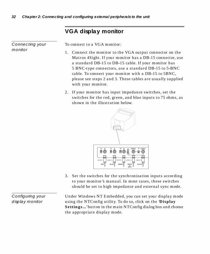
VGA display monitor
Connecting your monitor
To connect to a VGA monitor:
1. Connect the monitor to the VGA output connector on the Matrox 4Sight. If your monitor has a DB-15 connector, use a standard DB-15 to DB-15 cable. If your monitor has 5 BNC-type connectors, use a standard DB-15 to 5-BNC cable. To connect your monitor with a DB-15 to 5BNC, please see steps 2 and 3. These cables are usually supplied with your monitor.
2. If your monitor has input impedance switches, set the switches for the red, green, and blue inputs to 75 ohms, as shown in the illustration below.
3. Set the switches for the synchronization inputs according to your monitor’s manual. In most cases, these switches should be set to high impedance and external sync mode.
Configuring your display monitor
Under Windows NT Embedded, you can set your display mode using the NTConfig utility. To do so, click on the ‘Display Settings...’ button in the main NTConfig dialog box and choose the appropriate display mode.
GR B HSYNC VSYNC
( B N C ) ( B N C ) ( B N C )( B N C )( B N C )
INT
EXT
75757575
RED BLUE GREEN WHITEor
GRAY
BLACK

LAN options 33
The available display modes are:
LAN options
Connecting to your network
The Ethernet connector allows you to connect to a LAN in either a 10BaseT or 100BaseT operation mode. To connect to a LAN in 100BaseT mode, use an Unshielded Twisted Pair Category 5 (UTP5) cable. To connect to a LAN in 10BaseT mode, use a UTP5 or UTP3 cable.
Peer-to-peer connections
When connecting a Matrox 4Sight unit in a peer-to-peer configuration, you will have to use a crossover network cable. Build this special cable based on the following table using an Unshielded Twisted Pair Category 5 (UTP5) cable. An RJ45 connector must be attached to each end of the crossover cable. In the table, each row represents a wire of the cable.
Display size Available Colors Refresh Rates
640 x 480 256 colors 60, 72 or 75 Hz
640 x 480 65536 colors 60, 72 or 75 Hz
800 x 600 256 colors 60, 72 or 75 Hz
800 x 600 65536 colors 60, 72 or 75 Hz
1024 x 768 256 colors 60, 70 or 75 Hz
1024 x 768 65536 colors 60, 70 or 75 Hz
1280 x 1024 256 colors 60 or 75 Hz
34 Chapter 2: Connecting and configuring external peripherals to the unit
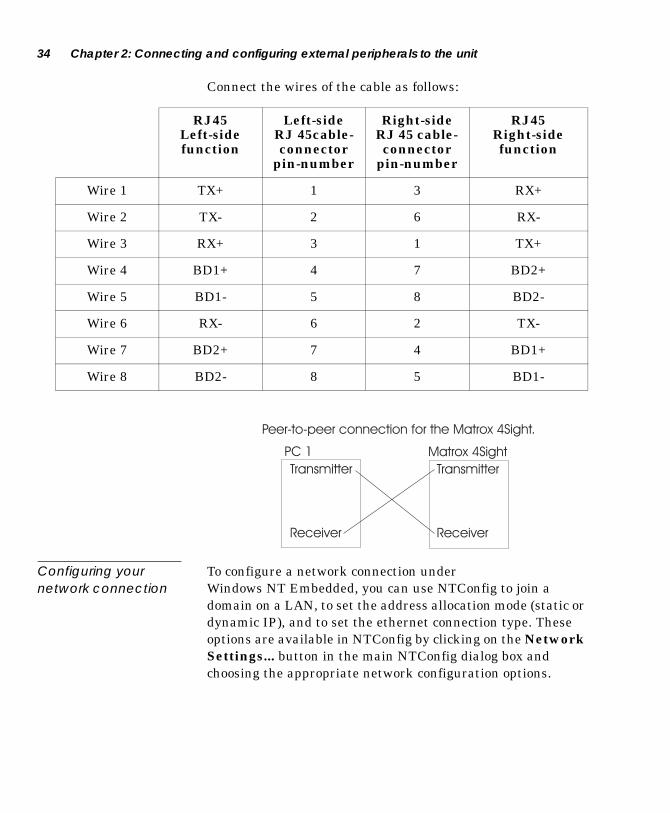
Connect the wires of the cable as follows:
Configuring your network connection
To configure a network connection under Windows NT Embedded, you can use NTConfig to join a domain on a LAN, to set the address allocation mode (static or dynamic IP), and to set the ethernet connection type. These options are available in NTConfig by clicking on the Network Settings... button in the main NTConfig dialog box and choosing the appropriate network configuration options.
RJ45 Left-side function
Left-side RJ 45cable-connector
pin-number
Right-side RJ 45 cable- connector
pin-number
RJ45 Right-side function
Wire 1 TX+ 1 3 RX+
Wire 2 TX- 2 6 RX-
Wire 3 RX+ 3 1 TX+
Wire 4 BD1+ 4 7 BD2+
Wire 5 BD1- 5 8 BD2-
Wire 6 RX- 6 2 TX-
Wire 7 BD2+ 7 4 BD1+
Wire 8 BD2- 8 5 BD1-
Transmitter
Receiver
Transmitter
Receiver
PC 1 Matrox 4Sight
Peer-to-peer connection for the Matrox 4Sight.

LAN options 35
Joining a domain in Windows NT Embedded
To join a domain in Windows NT Embedded, you must use NTConfig. From the primary NTConfig interface, click on the Network Settings..., button and then proceed according to the following steps:
1. Click on the Join Domain button in the Network Settings... dialog box.
2. Enter the domain name you would like to join.
3. Enter a user account name recognized by the primary domain controller. This account name must be suitable so that the domain controller can add your machine account on the domain.
4. Enter the user account password that will be required.
5. When you leave NTConfig, you will be notified that you must re-boot the unit for the new settings to take effect.
6. When you re-boot the Matrox 4Sight unit, you will be able to choose a domain name in the logon box. Note that the user account name and password must correspond to an active user account on the domain at logon time.
You might also need to provide your domain user account with administrative capabilities on the Matrox 4Sight unit. To do so:
1. Type ‘Usrmgr’ at the command prompt. The User Manager dialog box appears.
2. In the Groups selection box, double-click on Administrators. The Local Group Properties dialog box appears.
3. Click on the Add button to display the user accounts for the selected domain you have joined.
4. Select and add your user account to the Administrators list. You will now have administrative privileges on the local Matrox 4Sight unit when you log into the domain.

36 Chapter 2: Connecting and configuring external peripherals to the unit
Communication modes
The communication mode for an Ethernet interface defines how it adapts its settings when connected to another Ethernet interface. Supported modes are:
■ Auto sense mode: In this mode, the local Ethernet interface advertises its best communication mode, which is 100 Mbits in full duplex, but is controlled by its link partner (Slave). If its link partner is in auto sense mode Matrox 4Sight will adapt its communication mode (both speed and duplex) according to the link information it receives from the link partner. The Ethernet interface will adapt to its partner such that the maximum rate of communication is reached. However, if the link partner is in forced mode, the Ethernet interface will use a parallel detection algorithm that is only capable of determining the speed of the link. The duplex mode will be set to half, by default.
■ Advertised mode1: In this mode, the local Ethernet controller is in control of the speed and duplex mode of communication (Master). It will communicate its settings to its link partner and alter the partner’s communication mode to maximize communication rate if the link partner is in auto sense mode. If the link partner is in forced mode, the ethernet controller will enter into a parallel detection algorithm that is only capable of determining the speed of the link. The duplex mode will be set to half, by default.
■ Forced mode: In this mode, you set the local Ethernet interface options (speed and duplex mode) and these options do not change regardless of environment.
To avoid problems when connecting two Ethernet interfaces, the communication modes of the interfaces must match, that is their speed and duplex modes must be the same. For successful peer-to-peer communication both computers must have matching duplex modes. Unmatched modes will result in a very low bandwidth and poor communication. This means that the interfaces must both be in full auto sense mode, or they must both operate at the same speed and duplex mode.
1. The Advertised Mode is not currently supported on Matrox 4Sight units that have an Intel Ethernet controller.

Printing devices 37
Printing devices
The Matrox 4Sight integrated unit can output data to a printer. To output to a printer, proceed according to the following steps:
1. At the command prompt, type explorer to launch Windows NT Explorer.
2. Click on Printers (Desktop\My Computer\Printers).
3. Click on Add Printer.
4. Proceed as you would if you were operating under a full Windows NT Workstation operating system.
Note: If you are installing a network printer, you will have to join a domain, and then include the domain account in the list of administrators on that computer. To do so, see Joining a domain in Windows NT Embedded in this chapter.
Video Input devices
The Matrox 4Sight integrated unit contains a factory installed Matrox Meteor-II frame grabber, in either the standard version or the multi-channel version. The Matrox Meteor-II/ Standard frame grabber can accept composite (CVBS) and component (Y/C) video in NTSC/PAL format, and convert it to RGB 8:8:8, YUV 4:2:2 (stored in YUYV format) or YUV 4:1:1, with either square pixels or CCIR-601 resolutions. It can also convert monochrome video in a RS-170/CCIR video format with square pixels or CCIR-601 resolutions. Further, the Matrox Meteor-II/Standard frame grabber can switch between up to twelve independent composite or six Y/C video sources. The Matrox Meteor-II/Multi-Channel frame grabber, on the other hand, can capture monochrome or component RGB video signals from standard and non-standard cameras. The Matrox Meteor-II/Multi-channel can switch between input from two RGB or six monochrome cameras.
On the front panel of the chassis, Matrox 4Sight has an input connector, which is hard-wired to the Matrox Meteor-II board through an internal connection. In order to permit this internal connection, the video input connector of the Matrox Meteor-II
38 Chapter 2: Connecting and configuring external peripherals to the unit
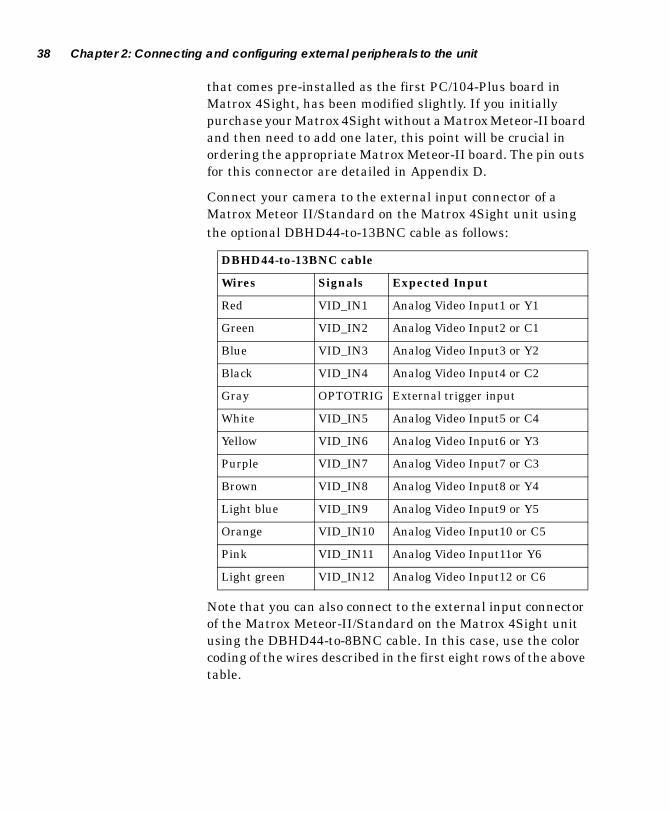
that comes pre-installed as the first PC/104-Plus board in Matrox 4Sight, has been modified slightly. If you initially purchase your Matrox 4Sight without a Matrox Meteor-II board and then need to add one later, this point will be crucial in ordering the appropriate Matrox Meteor-II board. The pin outs for this connector are detailed in Appendix D.
Connect your camera to the external input connector of a Matrox Meteor II/Standard on the Matrox 4Sight unit using the optional DBHD44-to-13BNC cable as follows:
Note that you can also connect to the external input connector of the Matrox Meteor-II/Standard on the Matrox 4Sight unit using the DBHD44-to-8BNC cable. In this case, use the color coding of the wires described in the first eight rows of the above table.
DBHD44-to-13BNC cable
Wires Signals Expected Input
Red VID_IN1 Analog Video Input1 or Y1
Green VID_IN2 Analog Video Input2 or C1
Blue VID_IN3 Analog Video Input3 or Y2
Black VID_IN4 Analog Video Input4 or C2
Gray OPTOTRIG External trigger input
White VID_IN5 Analog Video Input5 or C4
Yellow VID_IN6 Analog Video Input6 or Y3
Purple VID_IN7 Analog Video Input7 or C3
Brown VID_IN8 Analog Video Input8 or Y4
Light blue VID_IN9 Analog Video Input9 or Y5
Orange VID_IN10 Analog Video Input10 or C5
Pink VID_IN11 Analog Video Input11or Y6
Light green VID_IN12 Analog Video Input12 or C6

IEEE 1394 ports 39
To connect your camera to the external input connector of a Meteor-II/Multi-Channel on a Matrox 4Sight unit, use the optional DBHD44-to-8BNC cable as follows:
IEEE 1394 ports
The IEEE 1394 ports allow you to connect to any IEEE 1394 DCS-compliant camera in an IEEE 1394 tree topology. To connect your IEEE 1394 devices you use a 6-wire IEEE 1394 cable.
For further information, consult:
■ Anderson, Don. FireWire System Architecture. Reading, Massachusetts: Mindshare Inc., 1998.
■ Henehan, Burke. "1394 Firewire Hardware Design Considerations." Multimedia Systems Design Mar. 1998.
■ http://www.msdmag.com
DBHD44-to-8BNC cable
Wires Signals Expected Input
Red VID1_IN1 Analog Video Input1, R1
Green VID1_IN2 Analog Video Input2, G1
Blue VID1_IN3 Analog Video Input3, B1
Black SYNC_IN SYNC input
Gray OPTOTRIG External trigger input
White VID2_IN1 Analog Video Input4, R2
Yellow VID2_IN2 Analog Video Input5, G2
Purple VID2_IN3 Analog Video input6, B2

40 Chapter 2: Connecting and configuring external peripherals to the unit
Serial or parallel interface
You can connect to the RS-232 serial interface using a 9-pin RS-232 serial port cable.
You can connect to the Centronics parallel interface using a 25-pin parallel port cable.
Auxiliary I/Os on the Matrox 4Sight
Matrox 4Sight features 20 discrete LVTTL or TTL compatible digital I/Os, with interrupt-generation capabilities on the motherboard. Connect your device to these I/Os with a 25-pin custom cable. For efficient use of these I/Os, assign an interrupt line in the BIOS to the I/O pins. BIOS access is available by pressing the Delete key during the boot process. Alternatively, under Windows NT Embedded, you can assign an interrupt line to the I/O pins using the Auxiliary I/O Settings option of the NTConfig utility.
When accessing the Auxiliary I/O Settings dialog box with NTConfig, two columns will be shown. The first (left) column presents option buttons with their associated interrupt line numbers. The second (right) column presents each line’s corresponding functional device. In addition, the right column will reflect the status of each functional device by displaying the 'ENABLE' or 'DISABLE' keyword in front of the functional device item. It is important to note the device’s status because, when a specific interrupt line number has been selected with the option button, the associated device has to be disabled to leave the interrupt line free for the I/O pins. In certain situations, you will have to make a compromise between the interrupt line chosen and the functional devices needed by the application.
NTSC/PAL/RGB video output device 41
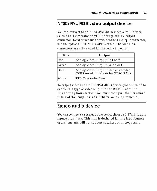
NTSC/PAL/RGB video output device
You can connect to an NTSC/PAL/RGB video output device (such as a TV monitor or VCR) through the TV output connector. To interface such devices to the TV output connector, use the optional DB9M-TO-4BNC cable. The four BNC connectors are color-coded for the following output.
To output video to an NTSC/PAL/RGB device, you will need to enable this type of video output in the BIOS. Under the Encoder options section, you must configure the Standard field and the Output mode field for your requirements.
Stereo audio device
You can connect to a stereo audio device through 1/8” mini audio input/output jack. This jack is designed for line input/output operations and will not support speakers or microphones.
Wire Output
Red Analog Video Output: Red or Y
Green Analog Video Output: Green or C
Blue Analog Video Output: Blue or encoded CVBS (used for composite NTSC/PAL)
White TTL Composite Sync

42 Chapter 2: Connecting and configuring external peripherals to the unit

Chapter 3: Managing the Matrox 4Sight under Windows NT Embedded
This chapter discusses the software environment for Matrox 4Sight.

44 Chapter 3: Managing the Matrox 4Sight under Windows NT Embedded
Windows NT Embedded
When you purchase a Matrox 4Sight unit with a DiskOnChip, the disk comes preloaded with a Windows NT Embedded operating system. Windows NT Embedded is a subset of standard Windows NT. Selectively chosen Windows NT components, including peripheral drivers, file systems, networking, and utilities are included in the embedded operating system, while other components are excluded. This operating system has small storage requirements, which makes it ideal for use with the DiskOnChip and in applications where some components of a full Windows NT operating system are unnecessary. The version of Windows NT Embedded included with the Matrox 4Sight unit reduces the storage requirements for the operating system to as little as 20 Mbytes.
Windows NT Embedded configuration
The version of Windows NT Embedded that is shipped with Matrox 4Sight is a version of Windows NT 4.0 (US-Edition), and includes Service Pack 5.0. This version of Windows NT is the only other officially supported operating system, besides the full version of Windows NT 4.0 (which can be installed on Matrox 4Sight’s hard drive). For a complete listing of components included with Windows NT Embedded see Component Listing for Windows NT Embedded in Appendix D: Technical reference

Using Windows NT Embedded command prompt 45
Using Windows NT Embedded command prompt
A key element in Windows NT Embedded is the command prompt window. Since Windows NT Embedded does not have the familiar shell of a full Windows NT Workstation, you must use the command prompt to send commands to Windows NT Embedded. Upon start up, Windows NT Embedded always displays the default command prompt window. This default command prompt executes the C:\AUTOST.BAT batch file. To open additional command prompt windows, call the Start command from a command prompt window. To close a window, click on the window’s close button or call Exit from the window. If you close the default window, you can reopen it as follows:
1. Press Crtl-Alt-Del. The Windows NT Security dialog box opens.
2. Click on the Task Manager button. This launches the Task Manager application.
3. Select New Task(Run...) from the File menu. The Create New Task dialog box opens.
4. In the edit field, type CMD or CMD /K C:\AUTOST.BAT, as needed.
A minimal Windows NT Explorer shell has been included to facilitate browsing through Windows NT Embedded files. To start the minimal explorer shell, use the ‘EXPLORER’ command line from a previously opened command prompt window.
46 Chapter 3: Managing the Matrox 4Sight under Windows NT Embedded
NTConfig: Basic configuration utility
A utility called NTConfig (NTConfig.exe) is available to configure basic information in the registry database of Windows NT Embedded.
NTConfig allows the user to directly control four groups of options through the graphical user interface (GUI). Four of these options, Network settings..., Display Settings..., Auxiliary I/O Settings, and Keyboard Settings..., have previously been discussed in Chapter 2: Connecting and configuring external peripherals to the unit. The final option is Auto Logon Settings... which is enabled by default, and configures the startup command line option and auto-logon settings.
You can refer to Appendix B of this manual for a list of all the registry entries that can be modified using NTConfig. Note, however, that we recommend that you use NTConfig to change these entries.
To access the NTConfig GUI, type NTConfig in a command prompt window. Upon exiting the utility, you will be asked if you want to reboot the unit immediately to activate the new configuration.
NTConfig also has a number of command line options, which allow you to perform several tasks from the Windows command prompt. NTConfig has the following command line options:
■ Reboot
■ Shutdown
■ DMACheck
■ Mem
■ Autopopup
For a complete description of these NTConfig options, please see Appendix B: NTConfig Windows NT Embedded registry.

Adding or modifying user accounts on Matrox 4Sight 47
Adding or modifying user accounts on Matrox 4Sight
The factory-configured Windows NT Embedded installation has the following pre-installed valid user account, which has administrative rights:
To create user accounts on Matrox 4Sight, use the program Usrmgr.exe, which is included in the Windows NT Embedded operating system. This is the common program from which you can add user accounts in a full version of Windows NT and has the same functionality in Windows NT Embedded. From the command prompt window, type Usrmgr and add user profiles as you would under a full Windows NT operating system environment.
Changing account passwords
You can change the password of an account using Usrmgr.exe. Alternatively, to change the password of the currently logged account you can follow these steps:
1. Logon using the account.
2. Press Ctrl-Alt-Del. The Windows NT Security dialog box is presented.
3. Click on the Change Password button. The Change Password dialog box is presented.
4. Change the password and click on the Ok button. If you don’t enter a password (that is, you press Enter instead of entering a password), the Auto-logon feature cannot be used. More explicitly, the Auto-logon feature requires that you use a password with at least one character.
User name Password
Administrator Administrator

48 Chapter 3: Managing the Matrox 4Sight under Windows NT Embedded
Changing the settings of the Auto-logon feature
By default, when Windows NT Embedded starts up, it automatically logs you onto the Matrox 4Sight unit using the Administrator account. You can change or disable the settings of the Auto-logon feature using NTConfig. To do so, use the Auto Logon Settings option of the NTConfig utility.
Bypassing the Auto-logon feature
When the Auto-logon feature is enabled, it is possible to get “trapped” in a Windows NT logon account that does not have administrative rights. This becomes important if you want to change certain system settings. To resolve this problem, press the Shift key just before the Begin Logon dialog box appears while Windows NT Embedded is booting. This will bypass the Auto-logon utility and you will be presented with the Logon Information dialog box. You can then enter the appropriate user name and password.
Setting environment variables
Although you can define your environment variables in C:\AUTOST.BAT so that they are automatically initialized at startup, these environment variables are only present in the command prompt window that processes C:\AUTOST.BAT. If you need environment variables that are available for any process, including Win32 non-console applications, add your environment variables to the registry database of Windows NT Embedded.
Setting the multi-boot option 49
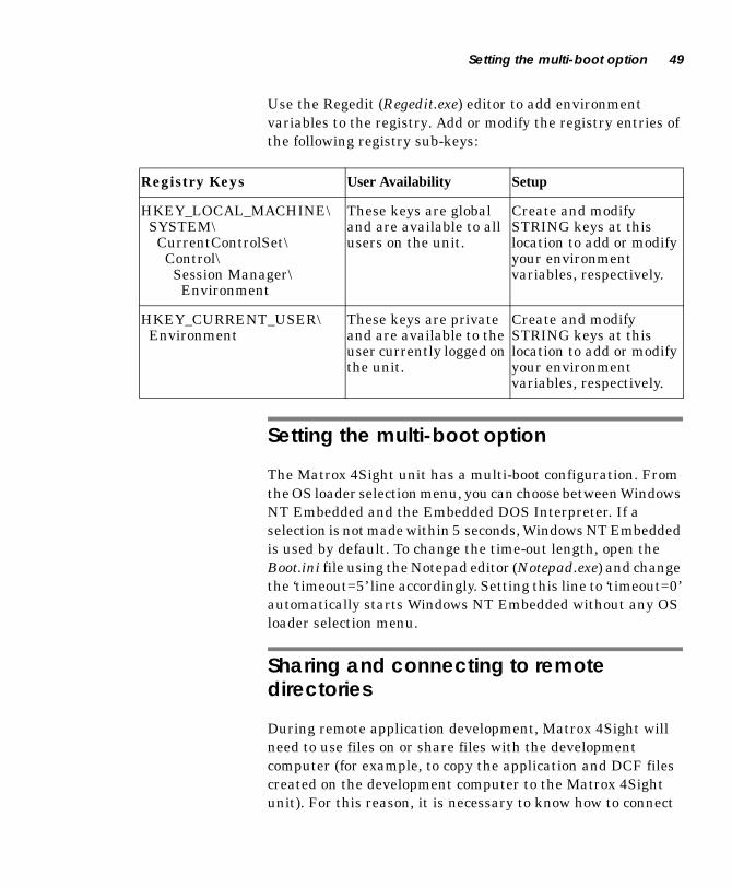
Use the Regedit (Regedit.exe) editor to add environment variables to the registry. Add or modify the registry entries of the following registry sub-keys:
Setting the multi-boot option
The Matrox 4Sight unit has a multi-boot configuration. From the OS loader selection menu, you can choose between Windows NT Embedded and the Embedded DOS Interpreter. If a selection is not made within 5 seconds, Windows NT Embedded is used by default. To change the time-out length, open the Boot.ini file using the Notepad editor (Notepad.exe) and change the ‘timeout=5’ line accordingly. Setting this line to ‘timeout=0’ automatically starts Windows NT Embedded without any OS loader selection menu.
Sharing and connecting to remote directories
During remote application development, Matrox 4Sight will need to use files on or share files with the development computer (for example, to copy the application and DCF files created on the development computer to the Matrox 4Sight unit). For this reason, it is necessary to know how to connect
Registry Keys User Availability Setup
HKEY_LOCAL_MACHINE\ SYSTEM\ CurrentControlSet\ Control\ Session Manager\ Environment
These keys are global and are available to all users on the unit.
Create and modify STRING keys at this location to add or modify your environment variables, respectively.
HKEY_CURRENT_USER\ Environment
These keys are private and are available to the user currently logged on the unit.
Create and modify STRING keys at this location to add or modify your environment variables, respectively.

50 Chapter 3: Managing the Matrox 4Sight under Windows NT Embedded
Matrox 4Sight to shared directories. This section describes how to achieve a connection between a Matrox 4Sight unit and another Windows NT network-connected computer.
To achieve a connection, the Matrox 4Sight unit must be able to communicate with the development computer through a TCP/IP network communication channel. Note that network components must be installed on both the Matrox 4Sight unit and the development computer. The network component is already installed in the version of Windows NT Embedded that is shipped with Matrox 4Sight.
Connect, share, and map drives from a Windows NT development computer as you normally would, using Explorer.
Connecting to a shared directory
From the Windows NT Embedded command prompt window, you can easily connect to a shared directory on a Windows NT Workstation development computer using the Net utility (NET.EXE). This utility allows you to mount logical drives to remote computers, so that files can be accessed by Matrox 4Sight. On the Matrox 4Sight unit running Windows NT Embedded, type at the prompt:
Replace MachineName with the name of the Windows NT Workstation development computer to which you want to connect and change ShareName to the name of the required, shared directory. To correctly identify yourself to the development computer, replace User_Account with your proper user account, as known by the development computer. Your user account password will be required during the connection.
Sharing directories on Matrox 4Sight
To share a directory on the Matrox 4Sight unit running Windows NT Embedded, type at the prompt:
Change Drive and Path to that of the directory to share on the Matrox 4Sight unit. Change ShareName to the name to associate with the specified directory (that is, the shared resource name).
NET USE Drive: \\MachineName\\ShareName /USER:User_Account
NET SHARE ShareName=Drive:\Path
Backing up your DiskOnChip image 51
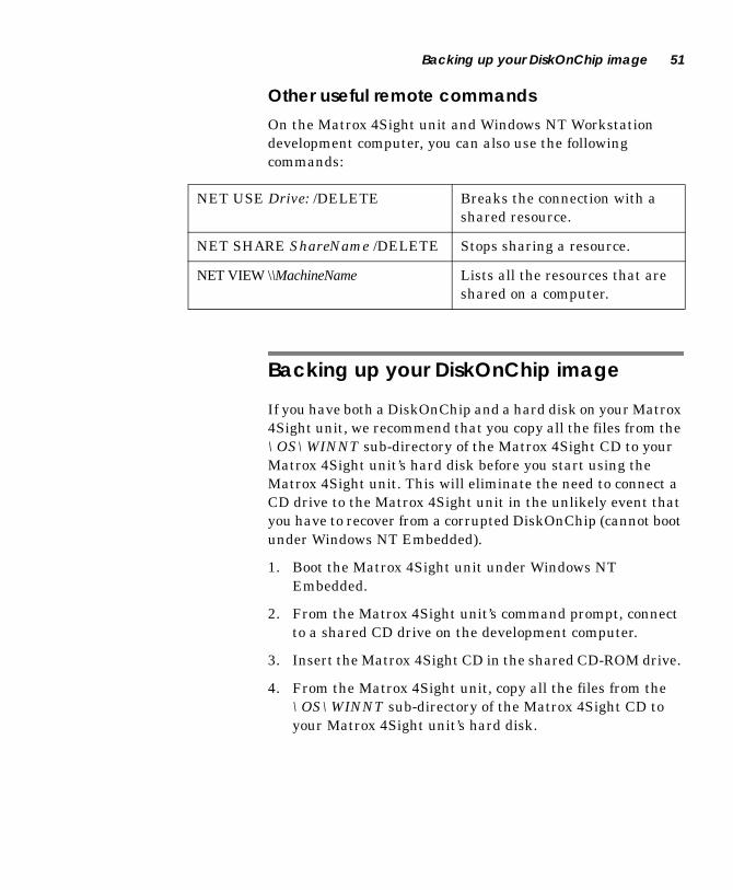
Other useful remote commands
On the Matrox 4Sight unit and Windows NT Workstation development computer, you can also use the following commands:
Backing up your DiskOnChip image
If you have both a DiskOnChip and a hard disk on your Matrox 4Sight unit, we recommend that you copy all the files from the \OS\WINNT sub-directory of the Matrox 4Sight CD to your Matrox 4Sight unit’s hard disk before you start using the Matrox 4Sight unit. This will eliminate the need to connect a CD drive to the Matrox 4Sight unit in the unlikely event that you have to recover from a corrupted DiskOnChip (cannot boot under Windows NT Embedded).
1. Boot the Matrox 4Sight unit under Windows NT Embedded.
2. From the Matrox 4Sight unit’s command prompt, connect to a shared CD drive on the development computer.
3. Insert the Matrox 4Sight CD in the shared CD-ROM drive.
4. From the Matrox 4Sight unit, copy all the files from the \OS\WINNT sub-directory of the Matrox 4Sight CD to your Matrox 4Sight unit’s hard disk.
NET USE Drive: /DELETE Breaks the connection with a shared resource.
NET SHARE ShareName /DELETE Stops sharing a resource.
NET VIEW \\MachineName Lists all the resources that are shared on a computer.

52 Chapter 3: Managing the Matrox 4Sight under Windows NT Embedded
Logging off or shutting down Matrox 4Sight
To logoff, press Ctrl-Alt-Del to access the Windows NT Security dialog box. Click the Logoff... button, and then click the Ok button to complete the logoff process.
To properly shut down Windows NT Embedded, press Ctrl-Alt-Del and then click on the Shut Down button. Select the shut down method and then click on the Ok button to complete the shut down process.
With the appropriate applications, you can also shut down or logoff the Matrox 4Sight remotely using the NTConfig /Shutdown or /Reboot commands, respectively.
Guidelines for setting up remote management of the Matrox 4Sight unit
To exploit remote management potential, you can issue commands between a client (development PC) and a server (Matrox 4Sight) through a TCP/IP communication channel. You will have to design and install applications to send and interpret commands that perform the required operation. To develop these applications, refer to your Win32 API documentation for a description of functions that exploit network communication and functions that manage processes.

Chapter 4: Developing an application for Matrox 4Sight under Windows NT Embedded
This chapter discusses the implementation and development of an application for Matrox 4Sight under Windows NT Embedded.
54 Chapter 4: Developing an application for Matrox 4Sight under Windows NT Embedded
Application development
To achieve the very small space requirements demanded by the DiskOnChip, much of the familiar shell of the full Windows NT operating system has not been included in the version of Windows NT Embedded shipped with the Matrox 4Sight unit. The lack of a familiar shell means that you might find Windows NT Embedded slightly awkward initially. This chapter explains how to develop an application for Matrox 4Sight from a remote development computer. The following is a broad outline of the necessary steps:
1. Code and compile your application on the development computer.
2. Optionally, debug the application on your development computer if you have the necessary hardware in place to do so.
3. Copy your application to the Matrox 4Sight unit.
4. Run the application on the Matrox 4Sight unit.
5. Remotely debug your application, if still necessary.
6. Remove unnecessary files from the Matrox 4Sight unit.
Note that to code and compile a MIL/MIL-Lite application, it is necessary to first purchase and install a MIL/MIL-Lite package on your development computer. Ensure that it has the same version and build numbers as the redistribution version on the Matrox 4Sight CD. Refer to the readme file on the Matrox 4Sight CD for details.
To do preliminary debugging on your development computer (optional step), ensure that you have the necessary hardware in place to do so (for example, a Matrox Meteor-II frame grabber). If the application is a MIL application, you must also attach the MIL hardware key to the parallel port of the machine running the application. If possible, use the same version (service pack) of Windows NT as the version from which Windows NT Embedded was created.

Installing a MIL application 55
Installing a MIL application
To install a MIL application on Matrox 4Sight, you must copy the application’s files to the Matrox 4Sight unit. To do so:
1. On the Matrox 4Sight unit, share the target directory. For instructions on sharing directories see Chapter 3: Managing the Matrox 4Sight under Windows NT Embedded.
2. On your development computer, connect and map a logical drive to this shared directory.
3. On your development computer, switch to the logical drive mapped to the target Matrox 4Sight directory. Change the current directory to the sub-directory in which you want your application to reside.
4. Copy the MIL application files from the development computer to the Matrox 4Sight unit. Make sure to copy the application’s EXE file, applicable DLL files, and DCF files (if used).
5. The version of the MIL DLL files that come pre-installed on the DiskOnChip are sufficient to run a MIL-Lite application. If your application uses a MIL image processing module, you must copy this module’s files from the Matrox 4Sight CD to the Matrox 4Sight unit. To copy these files, place the Matrox 4Sight CD in the CD drive of your development computer, share this drive, and from the Matrox 4Sight unit, connect and map a logical drive to this CD drive (discussed earlier).
6. For a MIL application, you should provide a MIL run-time license to run the application. Refer to the MIL User Guide for more information.
To demonstrate the above concepts, the following leads you through the installation of the example application, Mfocus.exe, on a Matrox 4Sight unit. We will make the following assumptions regarding:
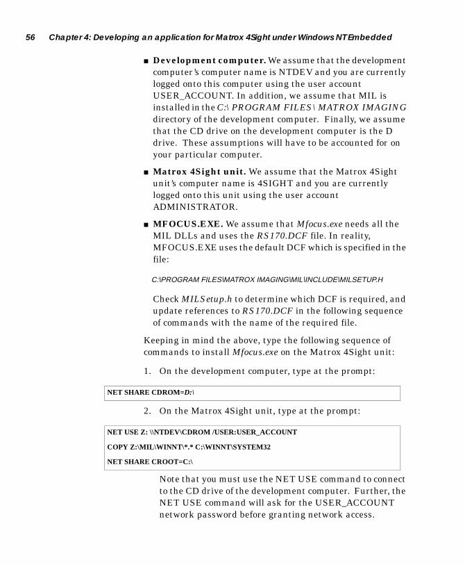
56 Chapter 4: Developing an application for Matrox 4Sight under Windows NT Embedded
■ Development computer. We assume that the development computer’s computer name is NTDEV and you are currently logged onto this computer using the user account USER_ACCOUNT. In addition, we assume that MIL is installed in the C:\PROGRAM FILES\MATROX IMAGING directory of the development computer. Finally, we assume that the CD drive on the development computer is the D drive. These assumptions will have to be accounted for on your particular computer.
■ Matrox 4Sight unit. We assume that the Matrox 4Sight unit’s computer name is 4SIGHT and you are currently logged onto this unit using the user account ADMINISTRATOR.
■ MFOCUS.EXE. We assume that Mfocus.exe needs all the MIL DLLs and uses the RS170.DCF file. In reality, MFOCUS.EXE uses the default DCF which is specified in the file:
C:\PROGRAM FILES\MATROX IMAGING\MIL\INCLUDE\MILSETUP.H
Check MILSetup.h to determine which DCF is required, and update references to RS170.DCF in the following sequence of commands with the name of the required file.
Keeping in mind the above, type the following sequence of commands to install Mfocus.exe on the Matrox 4Sight unit:
1. On the development computer, type at the prompt:
2. On the Matrox 4Sight unit, type at the prompt:
Note that you must use the NET USE command to connect to the CD drive of the development computer. Further, the NET USE command will ask for the USER_ACCOUNT network password before granting network access.
NET SHARE CDROM=D:\
NET USE Z: \\NTDEV\CDROM /USER:USER_ACCOUNT
COPY Z:\MIL\WINNT\*.* C:\WINNT\SYSTEM32
NET SHARE CROOT=C:\

Installing an ActiveMIL/ActiveMIL-Lite application 57
3. On the development computer, type at the prompt:
After typing the above sequence of commands, all the files required to run Mfocus.exe should be installed on Matrox 4Sight.
Installing an ActiveMIL/ActiveMIL-Lite application
If your application is an ActiveMIL/ActiveMIL-Lite application, you must follow the steps outlined in the MIL/MIL-Lite documentation.
Note that to code and compile a MIL/MIL-Lite application, it is necessary to first purchase and install a MIL/MIL-Lite package on your development computer. Ensure that it has the same version and build numbers as the redistribution version on the Matrox 4Sight CD. Refer to the readme file on the Matrox 4Sight CD for details. Additionally, before calling the NET SHARE command in step 2, you must add the following line:
for ActiveMIL, or
for ActiveMIL-Lite.
ActiveMIL controls can be used in applications built using Visual C++ 6.0. They can also be used with applications that are built using Visual Basic 6.0. Note, however, that you can not perform remote debugging using Visual Basic 6.0.
NET USE R: \\4SIGHT\CROOT /USER:ADMINISTRATOR
COPY “C:\PROGRAM FILES\MATROX IMAGING\MIL\EXAMPLES\MFOCUS.EXE” R:\MIL\EXAMPLES
COPY “C:\PROGRAM FILES\MATROX IMAGING\DRIVERS\METEOR_II\DCF\RS170.DCF” R:\MIL\DRIVERS\METEOR_II\DCF
COPY Z:\ACTIVEMIL\WINNT\*.* C:\WINNT\SYSTEM32
COPY Z:\ACTIVEMILLITE\WINNT\*.* C:\WINNT\SYSTEM32
58 Chapter 4: Developing an application for Matrox 4Sight under Windows NT Embedded
Remote debugging on Matrox 4Sight using Microsoft Visual C++ 6.0
Microsoft Visual C++ 6.0 has the ability to debug applications running on a remote computer such as a Matrox 4Sight unit (the target computer). From the development computer, Microsoft Visual C++ 6.0 controls debugging using a remote debug monitor application, called MSVCMON (Msvcmon.exe), on the target computer.
The development computer communicates with the target computer through a network communication channel. Note that network components must be installed on both the development computer and the target computer. The network component is already installed in the version of Windows NT Embedded that is provided with Matrox 4Sight.
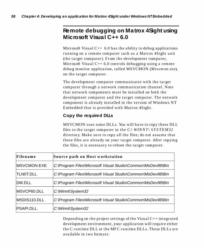
Copy the required DLLs
MSVCMON uses some DLLs. You will have to copy these DLL files to the target computer in the C:\WINNT\SYSTEM32 directory. Make sure to copy all the files; do not assume that these files are already on your target computer. After copying the files, it is necessary to reboot the target computer.
Depending on the project settings of the Visual C++ integrated development environment, your application will require either the C runtime DLL or the MFC runtime DLLs. These DLLs are available in two formats:
Filename Source path on Host workstation
MSVCMON.EXE C:\Program Files\Microsoft Visual Studio\Common\MsDev98\Bin
TLN0T.DLL C:\Program Files\Microsoft Visual Studio\Common\MsDev98\Bin
DM.DLL C:\Program Files\Microsoft Visual Studio\Common\MsDev98\Bin
MSVCP60.DLL C:\Winnt\System32
MSDIS110.DLL C:\Program Files\Microsoft Visual Studio\Common\MsDev98\Bin
PSAPI.DLL. C:\Winnt\System32

Remote debugging on Matrox 4Sight using Microsoft Visual C++ 6.0 59
■ The DLLs without debugging information are Msvcrt.dll, Msvcirt.dll, and Mfc42.dll. They are already installed on the Matrox 4Sight unit.
■ The DLLs with debugging information are Msvcrtd.dll, Msvcirtd.dll, and Mfc42d.dll. It might be necessary to copy these files to your target computer for remote debugging if the application is using them. These files can be found in the C:\WINNT\SYSTEM32 directory on your development computer.
DebuggingAfter having copied all relevant files, you can begin debugging remotely from your development computer. The Matrox 4Sight unit will use its local DLL’s during the remote debugging procedure. Note that for a MIL application, a MIL run-time license will not let you debug your application, even if you are debugging it remotely. The hardware key included with the MIL development package must be connected to Matrox 4Sight’s parallel port. To begin debugging:
1. We suggest sharing one directory (either on the development, the target, or another network machine) common to both the development and target computers. Edit and compile your application in this directory, move any required third-party DLLs into this directory, and then access these files in place. It is easier to share a directory; otherwise, you will have to copy these files manually from the development computer to the target computer.
2. On the development computer, load your project into Microsoft Visual C++.
3. Select Settings from the Project menu. The Project Settings dialog box is presented.
4. Choose the Debug property sheet.
5. Select General from the Category list box, and set the following items:
❐ Executable for Debug Session: Specify the name and path of the executable file so that the development computer can locate it.

60 Chapter 4: Developing an application for Matrox 4Sight under Windows NT Embedded
❐ Working Directory: Leave this field blank.
❐ Remote Executable Path: Specify the name and path of the executable file so that the target computer can locate it.
6. From the command prompt on the target computer, run the remote debug monitor MSVCMON. In the Visual C++ Debug Monitor window, click on the Settings button. The Settings dialog box is presented. Enter the development computer’s computer name in the Target machine name edit field. In the Visual C++ Debug Monitor window, click on the Connect button to start the connection.
7. On the development computer, select Debugger Remote Connection from the Build menu. The Remote Connection dialog box is presented. Select Network (TCP/IP) as the connection method, and then click on the Settings button. In the Target machine name edit field of the presented dialog, enter the target Matrox 4Sight unit’s computer name (do not use backslashes in the machine’s name).
8. Click OK and start debugging as usual.
9. When Visual C++ tries to access the symbolic information of the DLLs that are used by your application, Visual C++ will ask you to enter the location of the dependent DLLs if they are not on your development computer. Visual C++ may have difficulty locating the proper DLLs if the service packs differ from Matrox 4Sight to the development computer. The Find Local Module dialog box (which will appear automatically) allows you enter this information. Enter the full path of each DLL listed in the dialog; this path must include the machine name where the shared directory is located.
To ensure fast remote debugging, close any unneeded debugger windows to minimize the amount of information that must be sent across the connection. Also, minimize the use of data breakpoints.

Remote debugging on Matrox 4Sight using Microsoft Visual Basic 61
Remote debugging on Matrox 4Sight using Microsoft Visual Basic
Remote debugging is not supported under Windows NT Embedded for Visual Basic applications.
Working with MIL
When developing a MIL application for Matrox 4Sight, there are several things to note.
It is important to note that MIL can automatically perform YUV to RGB transformations and vice versa. MIL performs these transformations automatically when copying or grabbing into an image buffer of the required type.
Using the 1394 ports When using the IEEE 1394 ports, you can only use cameras that are compliant with the IEEE 1394 Digital Camera Specifications. In addition, once the MIL Matrox Meteor-II 1394 driver is installed, you can only use these cameras through MIL. Furthermore, MIL does not support the hot-plugging capabilities inherent in the IEEE 1394 standard.
Using the auxiliary I/Os To use the auxiliary I/Os on Matrox 4Sight from MIL, you must first assign an interrupt line to the group of I/Os in the BIOS. These I/Os can then be controlled from within MIL. Refer to the MIL/MIL-Lite Board-Specific Notes for more information.
Displaying grabbed images
When displaying grabbed images, the pre-installed Matrox Meteor-II driver can take advantage of the National
Semiconductor® Geode™ GXLV graphics controller’s overlay capabilities and use MIL’s DirectDraw underlay-surface display capabilities. In this mode, Matrox Meteor-II does not need any CPU intervention to maintain a live image display, with or without overlay. By default, the Matrox Meteor-II driver uses this mode.
62 Chapter 4: Developing an application for Matrox 4Sight under Windows NT Embedded
Automatically launching applications
With Matrox 4Sight, you can use the C:\AUTOST.BAT file to run your application automatically at startup.The Autost.bat file is a batch file that is called by default at startup. When a BAT file is called, each line in this file is interpreted and executed by the operating system.
The C:\AUTOST.BAT file might be processed before some Windows NT Embedded device driver initializations are complete. Therefore, if you want to launch your application from Autost.bat, you must synchronize the execution of your application with the end of the MIL driver initializations using the syncserv command.
SyncServ [ServiceName] [/WAIT] [/STEP] [/TIMEOUT] [/DOT] [/INFO] [/INFOF][/ERROR][/QUIET]
To do so, add the command needed to run your application after calls to the syncserv command. This ensures that your application is started after the driver is initialized.
For example, the MIL mfocus.exe example, which demonstrates continuous image capture, is launched from C:\AUTOST.BAT. Two syncserv commands with the wait option are used to synchronize the execution of mfocus.exe with the end of the initialization of the Matrox Meteor-II driver and the Matrox Meteor-II/1394 driver. You can replace the call to mfocus.exe with the call to your application.
Note that Autost.bat is executed by default because Windows NT Embedded executes a shell command line that is stored in the registry. By default, the shell command line is set to the following:
CMD /K C:\AUTOST.BAT

Removing unnecessary files from Matrox 4Sight 63
Removing unnecessary files from Matrox 4Sight
To achieve a smaller footprint, you can remove unused files from the Matrox 4Sight unit. Depending on the requirements of your application, there might be MIL files, installed as redistribution components of MIL, that can be removed.
To remove all components that are related to Matrox Meteor-II /Standard when Matrox Meteor-II /Multi-Channel is installed, use the Met2mc.bat file in Matrox 4Sight’s C:\MIL\BAT directory.
To remove all components that are related to Meteor-II /Multi-Channel when Matrox Meteor-II /Standard is installed, use the Met2std.bat file in Matrox 4Sight’s C:\MIL\BAT directory.
To remove all components that are not related to Matrox Meteor-II /1394, use the Met1394.bat file in Matrox 4Sight’s C:\MIL\BAT directory. This will leave support for only Matrox Meteor-II /1394 on your unit.
To remove all components that are not necessary for the final integration of the Matrox 4Sight unit, use the Cl_comp.bat file in Matrox 4Sight’s C:\MIL\BAT directory. This batch file deletes all DCF files, RES files, batch files in C:\MIL\BAT, examples in C:\MIL\EXAMPLES, and the Mildrv utility. After using this batch file, you must recopy all the DCF and RES files needed by your application to the Matrox 4Sight unit.

64 Chapter 4: Developing an application for Matrox 4Sight under Windows NT Embedded

Chapter 5: Managing the DiskOnChip
This chapter describes how to manage the DiskOnChip.
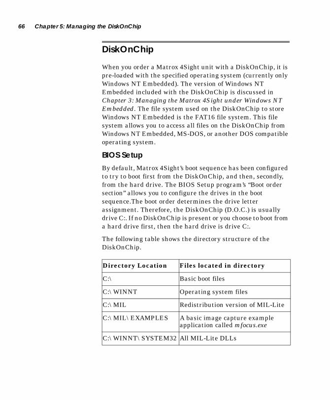
66 Chapter 5: Managing the DiskOnChip
DiskOnChip
When you order a Matrox 4Sight unit with a DiskOnChip, it is pre-loaded with the specified operating system (currently only Windows NT Embedded). The version of Windows NT Embedded included with the DiskOnChip is discussed in Chapter 3: Managing the Matrox 4Sight under Windows NT Embedded. The file system used on the DiskOnChip to store Windows NT Embedded is the FAT16 file system. This file system allows you to access all files on the DiskOnChip from Windows NT Embedded, MS-DOS, or another DOS compatible operating system.
BIOS SetupBy default, Matrox 4Sight’s boot sequence has been configured to try to boot first from the DiskOnChip, and then, secondly, from the hard drive. The BIOS Setup program’s “Boot order section” allows you to configure the drives in the boot sequence.The boot order determines the drive letter assignment. Therefore, the DiskOnChip (D.O.C.) is usually drive C:. If no DiskOnChip is present or you choose to boot from a hard drive first, then the hard drive is drive C:.
The following table shows the directory structure of the DiskOnChip.
Directory Location Files located in directory
C:\ Basic boot files
C:\WINNT Operating system files
C:\MIL Redistribution version of MIL-Lite
C:\MIL\EXAMPLES A basic image capture exampleapplication called mfocus.exe
C:\WINNT\SYSTEM32 All MIL-Lite DLLs

Replacing the DiskOnChip 67
Replacing the DiskOnChip
The DiskOnChip uses advanced wear levelling technology to maximize the lifespan of the DiskOnChip (see Chapter 9: Matrox 4Sight hardware reference). However, after extended read/write operations, the DiskOnChip will need to be replaced. If you need to save any data on the DiskOnChip, you should copy it to a shared drive or a local hard drive before removing and replacing the DiskOnChip. To remove the DiskOnChip, use a chip extraction tool. Be careful not to bend any pins while you are extracting the DiskOnChip.
You can replace the DiskOnChip with another 48 Mbyte DiskOnChip. If you buy the replacement DiskOnChip from Matrox, Windows NT Embedded and required drivers come preloaded on the DiskOnChip. If you buy your replacement DiskOnChip directly from M-Systems, you will have to install WindowsNT Embedded and required drivers on the replacement DiskOnChip. To do so, you can use the appropriate DiskOnChip image supplied on the Matrox 4Sight CD, as described in the next section.
Note that after inserting a new DiskOnChip, no BIOS software set-up is required. In addition, when operating under DOS or the Embedded DOS Interpreter, no DiskOnChip driver is required because of the DiskOnChip firmware.
DiskOnChip
Front panel
Pin 1
68 Chapter 5: Managing the DiskOnChip
Reinstalling the DiskOnChip image on your DiskOnChip
To (re)install the DiskOnChip image on your DiskOnChip, use the appropriate image file from the \OS\WINNT directory of the Matrox 4Sight CD. All the supported DiskOnChip sizes have a corresponding DiskOnChip image file. The number in the DiskOnChip image file name reflects the size of the DiskOnChip for which the file was created.
❖ Note: It is possible that single sectors or a group of sectors will get corrupted while the remainder of the DiskOnChip remains functional. If you can still boot from your DiskOnChip and you have a local hard disk available, you can boot under Embedded DOS, switch to the local hard drive and skip ahead to step 3.
1. Create a formatted MS-DOS bootable floppy disk with the MS-DOS system files on it.
2. Install a floppy drive on your Matrox 4Sight (see Chapter 6: Using the hard drive based Matrox 4Sight). Boot the Matrox 4Sight unit with this floppy disk. Note that, the floppy drive must be enabled in the BIOS. Also, note that Matrox 4Sight cannot boot from a CD drive.
3. If a hard disk is available in the Matrox 4Sight unit and if you have access to a previously copied DiskOnChip image file on the hard disk (see Chapter 3: Managing the Matrox 4Sight under Windows NT Embedded), you can use the previously copied file to reinstall the Windows NT Embedded operating system (DiskOnChip image) from the hard drive.
4. If you do not have access to an already copied DiskOnChip image file on the hard disk, you will have to install a CD drive in the Matrox 4Sight unit. Further, you will have to install its associated MS-DOS CD-ROM driver with Microsoft MSCDEX.EXE TSR utility from MS-DOS, which should be copied onto the bootable floppy disk. Refer to the Connecting IDE devices to install the CD drive.
Building your own Windows NT Embedded configuration 69
5. Change to the sub-directory in which you have copied the DiskOnChip image file and additional utilities files, or access the \OS\WINNT directory on the CD.
6. Type the command PUTDOC NTE48 to update the content of a 48 Mbyte DiskOnChip. If your DiskOnChip is a different size, replace NTE48 with the appropriate image file name.
Formatting the DiskOnChipIf you have an unformatted or corrupted DiskOnChip that does not respond to reinstalling the DiskOnChip image file, it will need to be formatted. To reformat (low-level) the DiskOnChip, use the DFORMAT C: command. The DFORMAT.EXE utility can be found on the Matrox 4Sight CD in the \UTILITIES\DISKONCHIP directory. The DFORMAT.EXE utility is a DOS compatible utility.
Building your own Windows NT Embedded configuration
If required, you can create your own image of a custom Windows NT Embedded configuration. To do so, Microsoft recommends a development computer consisting of the following:
■ 300 MHz Pentium-class processor.
■ 64 Mbytes of RAM.
■ A minimum of 20 Mbytes of free disk space.
■ An additional 70 Mbytes of disk space is recommended to store the generated image.
■ The Microsoft software packages Target Designer and Component Designer.
■ A Windows NT 4.0 operating system with Service Pack 4 and an SP1 version of Internet Explorer.
■ The Microsoft Visual C++ 6.0 development environment. This is needed to create Target Designer extensions (TDXs) for new components of your DiskOnChip image.
70 Chapter 5: Managing the DiskOnChip
You can then refer to Building NTE images with TD.doc on the root directory of the Matrox 4Sight CD, for a step-by-step procedure on how to recreate the NTE image shipped with Matrox 4Sight.
The manuals accompanying these software packages will indicate how you can create a custom version of Windows NT Embedded, as well as outline the licensing obligations that must be fulfilled.
Several components included in the Matrox-produced version of Windows NT Embedded are absolutely required to run MIL. For a complete list of these components, as well as an exhaustive list of components included with the factory installed version of Windows NT Embedded, see Appendix D.

Part 2: Making hardware, driver, and OS modifications


Chapter 6: Using the hard drive based Matrox 4Sight
This chapter introduces the second section of the manual dealing with the 4Sight as a hard drive based unit.

74 Chapter 6: Using the hard drive based Matrox 4Sight
Introduction
If you have ordered a Matrox 4Sight unit with only a hard drive, you will need to install an operating sytem. If you have ordered a Matrox 4Sight unit with a DiskOnChip and a hard drive, you might want to install an operating system on your hard drive. Although the DiskOnChip comes with Windows NT Embedded and an Embedded DOS interpreter, both of these operating systems are limited, and you might need a more complete one. In general, a complete operating system requires a hard drive, due to space limitations on the DiskOnChip.
In either case, you can install an operating system on a Matrox 4Sight hard drive by going through the following steps:
1. Power down the Matrox 4Sight unit, remove the cover and connect a CD drive, a floppy drive, and a hard drive (if one is not already installed).
2. Power up Matrox 4Sight (installation of these devices will probably obstruct the reinstallation of the chassis).
3. If you have just installed a hard drive you will need to enable it in the BIOS.
4. If you ordered the Matrox 4Sight unit with a DiskOnChip and an ATA hard drive installed, install Windows NT on the hard drive from the CD drive, and re-boot using the hard drive as the 1st boot device.
5. If your Matrox 4Sight has only a hard drive, use the floppy drive as the boot device. Your Matrox 4Sight will boot from the floppy drive, using the WINNT setup disks. Then, install the operating system onto the hard drive.
6. Refer to the installation manual of the operating system that you are installing for instructions.
7. Install appropriate device drivers.
8. Install the Microsoft developer platform, MSDEV. Refer to the appropriate manual for installation instructions, if you will be developing MIL applications on your Matrox 4Sight.
9. Install MIL/ActiveMIL.

Removing the Matrox 4Sight chassis 75
Removing the Matrox 4Sight chassis
To remove the Matrox 4Sight chassis:
▲ Warning 1. Unplug the Matrox 4Sight power cord.
2. Remove the appropriate screws on the side of the back panel of the Matrox 4Sight unit.
3. With the Matrox 4Sight unit laid flat, place your hands on top of the chassis and slowly slide the chassis so that it emerges from the back panel.
▲ Warning As you begin to slide the chassis out, you will be met with some resistance. This is due to the connectors on the back panel. Do not use excessive force to slide the chassis past these connectors; this can damage the connectors. Instead, ease the chassis past the connectors.
Back panel
1394
1 2 3
1
2Power
2.5 A
12 V
Serial ports
Parallel ports
Front panel

76 Chapter 6: Using the hard drive based Matrox 4Sight
Connecting to a floppy drive
You can connect a floppy drive using a 34-pin flat ribbon cable. Connect one end of the ribbon cable to the floppy drive and the other end to the connector highlighted in the following diagram of the Matrox 4Sight motherboard. You must also attach a power cable to the power connector on your floppy drive.
After connecting to a floppy drive, you must reconfigure the BIOS of the Matrox 4Sight in order to accomodate this change by using the BIOS Setup program. You may access this program by hitting the Delete key during the boot-up sequence.
Floppy disk connector
Back Panel
Front Panel
1
1 = Pin 1
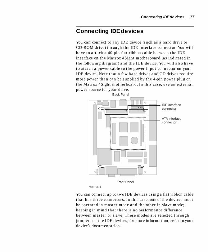
Connecting IDE devices 77
Connecting IDE devices
You can connect to any IDE device (such as a hard drive or CD-ROM drive) through the IDE interface connector. You will have to attach a 40-pin flat ribbon cable between the IDE interface on the Matrox 4Sight motherboard (as indicated in the following diagram) and the IDE device. You will also have to attach a power cable to the power input connector on your IDE device. Note that a few hard drives and CD drives require more power than can be supplied by the 4-pin power plug on the Matrox 4Sight motherboard. In this case, use an external power source for your drive.
You can connect up to two IDE devices using a flat ribbon cable that has three connectors. In this case, one of the devices must be operated in master mode and the other in slave mode; keeping in mind that there is no performance difference between master or slave. These modes are selected through jumpers on the IDE devices; for more information, refer to your device’s documentation.
Back Panel
Front Panel
IDE interfaceconnector
ATA interfaceconnector
1 1
1 = Pin 1

78 Chapter 6: Using the hard drive based Matrox 4Sight
After connecting an IDE hard drive or CD-ROM drive, you must notify Matrox 4Sight of this change in configuration, using the BIOS Setup program. The BIOS is accessed by pressing the Delete key during the boot procedure.
Also available for connecting additional IDE devices is an ATA connector (indicated in diagram) which allows the connection of an additional two ATA compliant devices, such as hard drives. If you need to connect two devices to this connector, you will have to connect them in a master/slave configuration and use a 44-pin flat ribbon cable that has three connectors.
Installing a full Windows NT Workstation on Matrox 4Sight
To install a full Windows NT Workstation on the Matrox 4Sight hard disk, you must install a CD drive and external floppy drive on your Matrox 4Sight unit. Then, refer to the Windows NT installation manual to install it.
Installing device drivers When installing a full Windows NT Workstation, you need to install custom device drivers located on the Matrox 4Sight CD. This section describes how to install each of these drivers.
Geode display driver
To install the Geode display driver:
1. From the Control Panel, click on the Display icon. The Display Properties dialog box is presented.
2. Select the Setting property page and click on the Display type button.
3. Then, click on the Change button. A dialog box allowing you to change the current display driver is presented.

Installing a full Windows NT Workstation on Matrox 4Sight 79
4. Click on the Have Disk button and then press the Browse button to specify the path of the Geode display driver files; they are located in the \DRIVERS\WINNT\DISPLAY directory of the Matrox 4Sight CD.
5. Select the National (Matrox Modified) Geode entry in the presented list box and click on the Ok button to start the installation of the driver. You must reboot the computer to use the new driver.
Geode IDE Ultra DMA driver
If you are using a hard disk that has Ultra DMA capabilities and you want to access these capabilities, it is necessary to install this driver.
To install the Geode IDE Ultra DMA Driver:
1. From the Control Panel, click on SCSI Adapters.
2. Select Drivers.
3. Select the ATAPI driver and then click on the Remove button.
4. Click the Add button.
5. Click Have Disk... and select the Geode UDMA driver by switching to the correct path of the Geode IDE drivers in the \DRIVERS\WINNT\IDE directory of the Matrox 4Sight CD. The installation will ask you to identify the path on two consecutive occasions.
6. Click Yes to restart your computer.
You will have to re-boot the computer for the new driver settings to take effect.
Geode sound driver
To install the Geode sound driver:
1. From the Control Panel, click on the Multimedia icon. The Multimedia Properties dialog box is presented.
2. Select the Devices property page and then select the Audio Devices entry from the tree list.

80 Chapter 6: Using the hard drive based Matrox 4Sight
3. Click on the Add button and select the Unlisted or Updated Driver entry.
4. Click on the Ok button to access the browse dialog. Press the Browse button to specify the path of the Geode sound driver files; they are located in the DRIVERS\WINNT\SOUND directory of the Matrox 4Sight CD.
5. Select the XpressAudio Driver entry in the presented list box and click on Ok to start the installation of the driver.
6. Leave the suggested I/O address, and press the Continue button when prompted for the XpressAudio Base I/O address. The XpressAudio Configuration dialog box is presented.
7. Select Disable as the MPU401 I/O Address and click Ok to end the installation.
8. You must reboot the unit to use the new driver.
Installing an Ethernet driver
In order to install the proper Ethernet driver on Windows NT Workstation, you must first detect the type of Ethernet controller that your Matrox 4Sight has. This detection must be done manually using a command prompt window, and a utility provided on the Matrox 4Sight CD. The detection steps are as follows:
1. Ensure that Windows NT Workstation has been installed without any network components.
2. Open a command prompt window.
3. Copy all the files (WHICHNET.BAT, DUMPPCI.EXE, and PCIDUMPR.SYS) from the \Drivers\winnt\network directory on the Matrox 4Sight CD to the C:\ drive.
4. Go to the C:\ command prompt window and type ‘WHICHNET’.
The utility will report either that a DAVICOM Ethernet controller or an INTEL Ethernet controller is present. If a DAVICOM Ethernet controller is present, you should follow the ‘Matrox Ethernet driver’ installation procedure.

Installing a full Windows NT Workstation on Matrox 4Sight 81
Alternatively, if an INTEL Ethernet controller is present, you should follow the ‘Intel Ethernet driver’ installation procedure.
Matrox Ethernet driver
To install the Matrox Ethernet driver:
1. From the Control Panel, click on the Network icon. Windows NT will let you install the network components and select the network adapter of your choice.
2. Enter the path of Matrox Ethernet driver files; they are located in the \DRIVERS\WINNT\NETWORK\DAVICOM directory of the Matrox 4Sight CD.
Select the DAVICOM driver from the presented list box and select the proper network connection type to use with the Ethernet adapter. You must reboot the computer to use the new driver.
Intel Ethernet driver
To install the Intel Ethernet driver:
1. From the Control Panel, click on the Network icon. Windows NT will let you install the network components and select the network adapter of your choice.
2. Enter the path of Intel Ethernet driver files; they are located in the \DRIVERS\WINNT\NETWORK\INTEL directory of the Matrox 4Sight CD.
3. Select the INTEL driver from the presented list box and select the proper network connection type to use with the Ethernet adapter. You must reboot the computer to use the new driver.

82 Chapter 6: Using the hard drive based Matrox 4Sight
M-Systems DiskOnChip driver
To install the M-Systems DiskOnChip driver, follow these steps:
1. Right-click on the trueffs.inf file in the \DRIVERS\WINNT\DISKONCHIP directory of the Matrox 4Sight CD.
2. Choose Install from the list of menu items.
3. Reboot your PC.
Windows NT will restart with the DiskOnChip mapped to C:\. Note that leaving the DiskOnChip mapped to the C:\ will cause Windows NT Workstation to store the paging file on the DiskOnChip. Since the paging file is written frequently, this can lead to early wearing on the DiskOnChip.
To set the DiskOnChip to any letter other than C:\, you should follow these steps:
1. Access the Disk Administrator tool, which is located under the Administrative Tools sub-menu list. The Administrative Tools menu item is accessible from the Start Programs menu.
2. Right-click on the disk (DiskOnChip) labelled C:.
3. Choose Assign Drive Letter... from the context menu presented. The Assign Drive Letter dialog box appears.
4. Choose a drive letter that is not currently assigned to a disk from the drop-down list box.
5. Reboot your PC to allow these changes to take effect. Another drive (other than the DiskOnChip) will automatically be assigned to C:\, but the DiskOnChip will retain the most recent drive letter assignment.
6. Optionally, you can then reassign the DiskOnChip’s drive letter assignment by repeating steps 1 through 4 using a more appropriate drive letter.
Note that you will not have to reboot your PC this time. Changes will take effect immediately once the disk/drive is reassigned, since you are not changing the location of the

Installing MIL/ActiveMIL 83
disk/drive containing the paging file (C:\ by default), and provided that no applications are currently running from the disk/drive selected.
Reassigning the hard disk to C:\
If necessary, you can reset your hard disk to C:\ in a two-step process. First, repeat steps 1 through 5 above for the disk that is currently assigned to C:\. Then, once that disk is reassigned, assign the hard disk to C:\.
Installing MIL/ActiveMIL
Prior to installing MIL or ActiveMIL you must install the Microsoft development platform MSDEV. Refer to the appropriate installation manual for installation instructions.
In addition to your MIL CD, you will require a hardware key (a two-sided, 25 pin connector) if you plan to use the Matrox 4Sight as a development PC for MIL applications. The key allows you to code, debug, and run your applications. Note that Intellicam, your digitizer configuration program, is installed with MIL; however, Matrox Intellicam will not work with an embedded operating system.
To install your MIL software:
1. Attach the hardware key to the parallel port of your computer. If another device such as a printer is attached to the parallel port, turn it off and disconnect it from the parallel port. Then, attach the hardware key to the parallel port, and connect the device to the other end of the hardware key. The presence of the hardware key will not cause any communication interference with your device.
2. Place the installation CD in an appropriate drive. The setup.exe program will run automatically.
During installation, you will be asked a number of questions, such as:
■ The drive and directory on which to install the program.
■ Your target operating system and compiler.
■ The type of Matrox hardware installed in your computer (for example, Matrox Meteor-II).

84 Chapter 6: Using the hard drive based Matrox 4Sight
■ The digitizer and display format to load into the default setup file, milsetup.h.
■ The amount of DMA linear non-paged memory to reserve for grab buffers. The amount of reserved DMA memory also establishes the amount of remaining RAM available to your operating system.
For a more thorough description of MIL installation information refer to the MIL User Guide manual. After installation, read the readme.txt file in the \MIL directory to determine where MIL files are located and how to compile and run the MIL examples.
Chapter 7: Additions to the Matrox 4Sight integrated unit
This chapter deals with additions that can be made to the Matrox 4Sight integrated unit in the provided chassis.

86 Chapter 7: Additions to the Matrox 4Sight integrated unit
Additions to the unit
The Matrox 4Sight integrated unit is designed to accommodate selected hardware additions. The primary step in making additions to the unit involves removing the chassis, discussed in Chapter 6: Using the hard drive based Matrox 4Sight. The following diagram provides a reference to motherboard connections:
L
A
H
B
C
FE
G
IJ
KM
N
OP
Q Q
D
R
On/off switch*
Power input*
Mouse input (top port) and keyboard input (bottom port)
2 serial ports
Parallel port (top) and 3 IEEE 1394 ports (bottom)
Audio input (top port) and output (bottom port)
Auxiliary I/Os (top port) and video input (bottom port)
TV output (top port) and VGA output (bottom port)
Ethernet connector
LEDs
Available if you purchase the Matrox 4Sight integrated unit*
TM
= DIMM slot
= Power connector**
= Floppy disk connector
= Power connector for additional IDE drivers
= IDE interface connector
= ATA (44) internal connector
= Connector to parallel port
= Hard drive (optional)
= Fan
= Flat panel backlight
= Flat panel
= DiskOnChip (optional)
= Connector to auxiliary I/Os
= Flash BIOS socket
= Ethernet controller
= National Semiconductor Geode GXLV processor
= PC/104- connectors
= PCI-to-PCI bridge
= Super I/O controller
= Battery
= Processor companion chip
connector
interface connector
Plus
*
A
B
C
D
E
F
G
H
I
J
K
L
M
N
O
P
Q
R
S
T
U
PC/104-expansion site
Plus
Matrox 4Sight components and connectors
S
T
Available on the stand-alone Matrox 4Sight motherboard**
U

Additions to the unit 87
Connecting an alternate hard drive
If you wish to connect an external hard drive, refer to Chapter 6: Using the hard drive based Matrox 4Sight.
Connecting to a flat panelMatrox 4Sight supports connection to any flat panel that complies with the VESA FPDI-1 specifications.
To interface a flat panel to Matrox 4Sight:
■ Attach a 41-pin flat ribbon cable to the interface connectors on your Matrox 4Sight and flat panel.
■ Attach a power cable from the flat panel backlight connector on Matrox 4Sight to the backlight power supply connector on your flat panel.
Installing a PC/104-Plus™ board
You can install up to three PC/104-Plus™ boards on the Matrox 4Sight motherboard in a stackthrough configuration, as shown below. Each board must be attached to the other through four jack screws.
PC/104(ISA) connector
TMTMPC/104-
(PCI) connectorPlus Matrox 4Sight motherboard
PC/104-board
PlusTM
PC/104-board
PlusTM
PC/104-board
PlusTM
module 1
module 2
module 3

88 Chapter 7: Additions to the Matrox 4Sight integrated unit
The following points are critical when connecting additional PC/104-Plus boards to the Matrox 4Sight.
■ The voltage I/O pins on the Matrox 4Sight PC/104-Plus connector are set to 3.3 V.
■ If you are installing a standard PC/104 board, it must be the top module, since it will normally not include the PCI bus.
■ Matrox 4Sight does not support PC/104 ISA boards that require:
❐ -12 V.
❐ DMA Master Mode.
You must configure multiple master-capable or interrupt-capable PC/104-Plus boards using their rotary switch; the rotary switch selects a specific PCI signal. It is recommended that you configure the first module installed (the module closest to the motherboard) to 0, the second to 1, and so on. If you are installing more than one PC/104-Plus board, the rotary switch on each board must be set as follows:
On the Matrox 4Sight integrated unit, the switch position for the Matrox Meteor-II frame grabber for PC/104-Plus is 0. This switch position cannot be modified.
The PCI shroud, a plastic case which protects the PCI connector pins, on your PC/104-Plus board (if present) should be removed before installation. The shroud is used to protect the PCI connector but hinders air circulation.
Module # Switch position1 0 or 42 1 or 53 2 or 6

Removing and installing memory from Matrox 4Sight 89
Removing and installing memory from Matrox 4Sight
The Matrox 4Sight motherboard features a 168-pin DIMM slot. This slot can support a 32, 64(default), or 128 Mbyte SDRAM module. This section describes how to remove/install an SDRAM module. Matrox 4Sight supports 3.3 V, unbuffered, PC/100-compliant SDRAM DIMMs.
Removing memory
To remove memory:
1. Spread the clips at each end of the module.
2. Lift the module out of the slot.
Installing memoryTo install memory:
1. Position the module over the DIMM slot, such that the notches along the module’s bottom edge align with the notches in the DIMM slot.
2. Gently insert the bottom edge of the module into the slot until you hear it snap into place.
DIMM slot
SDRAM module
Front panel

90 Chapter 7: Additions to the Matrox 4Sight integrated unit
Changing DMA memory settings At the factory, Matrox 4Sight’s memory settings were configured as follows:
■ Total Physical Memory reserved for Video Memory = 3584 Kbytes (3.5 Mb)
■ Total Physical Memory reserved for MIL DMA Buffers = 3584 Kbytes (3.5 Mb)
■ Total Physical Memory available for Windows NT Embedded = 58368 Kbytes (57 Mb)
To change the DMA memory size according to your application’s requirements, use the Mildrv utility (MILDrv.exe), as follows:
Replace [DMASIZE] with the amount of DMA memory, in Kbytes, to reserve for DMA buffers (grab buffers). Replace [SYSSIZE] with the amount of physical memory (RAM) installed on Matrox 4Sight minus the amount used as video memory (Matrox 4Sight uses part of physical memory as video memory (graphics display memory)). The default amount used as video memory is 3.5 Mbytes and is always located at the top of physical memory. This means that [SYSSIZE] must be set to 61952 for a 64 Mbytes unit or 127488 for a 128 Mbytes unit. For example, to reserve 3.5 Mbytes for DMA buffers on a 64 Mbytes computer, use the following command (leaving 57 Mbytes for Windows NT Embedded to run):
For a 128 Mbyte computer, use the following command:
You can use NTConfig with the /MEM option to obtain information on Matrox 4Sight’s memory settings.
There is one option in the BIOS Setup program that allows you to reserve specific amounts of video memory from the available external memory. Once you reserve video memory, it is no longer counted as available external memory. As mentioned,
MILDRV MTXDMA [DMASIZE] –PCMEMORYSIZE=[SYSSIZE] –UPDATE
MILDRV MTXDMA 3584 -PCMEMORYSIZE = 61952 -UPDATE
MILDRV MTXDMA 3584 -PCMEMORYSIZE = 127488 -UPDATE
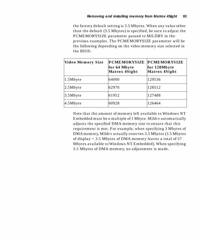
Removing and installing memory from Matrox 4Sight 91
the factory default setting is 3.5 Mbytes. When any value other than the default (3.5 Mbytes) is specified, be sure to adjust the PCMEMORYSIZE parameter passed to MILDRV in the previous examples. The PCMEMORYSIZE parameter will be the following depending on the video memory size selected in the BIOS:
Note that the amount of memory left available to Windows NT Embedded must be a multiple of 1 Mbyte. Mildrv automatically adjusts the specified DMA memory size to ensure that this requirement is met. For example, when specifying 3 Mbytes of DMA memory, Mildrv actually reserves 3.5 Mbytes (3.5 Mbytes of display + 3.5 Mbytes of DMA memory leaves a total of 57 Mbytes available to Windows NT Embedded). When specifying 3.5 Mbytes of DMA memory, no adjustment is made.
Video Memory Size PCMEMORYSIZEfor 64 Mbyte Matrox 4Sight
PCMEMORYSIZEfor 128Mbyte Matrox 4Sight
1.5Mbyte 64000 129536
2.5Mbyte 62976 128512
3.5Mbyte 61952 127488
4.5Mbyte 60928 126464
92 Chapter 7: Additions to the Matrox 4Sight integrated unit
Using the MILConfig utilityYou can also use the MILConfig utility to change the amount of reserved DMA memory from the factory default value of 3.5 Mbytes. The MILConfig utility is located in the MATROX IMAGING\MILCONFIG directory.
1. Run the MILConfig.exe utility. You will be presented with the dialog box Mil Configuration. Select the Non-paged memory tab.
Under the Current Settings section, you will be presented with the present settings of the non-paged memory size (DMA memory), as well as the computer memory size.
2. Under the New Settings section, type in the new amount of non-paged memory (DMA memory) you wish to reserve.
3. Click OK.

Part 3: Using the motherboard in a custom chassis

Chapter 8: Installing the Matrox 4Sight motherboard in a custom chassis
This chapter provides some guidelines for installing the Matrox 4Sight motherboard in a custom chassis.

96 Chapter 8: Installing the Matrox 4Sight motherboard in a custom chassis
Overview
This chapter provides general guidelines for safely using the Matrox 4Sight motherboard with a custom chassis, power supply, and fan. Specific instructions should be found in the documentation accompanying these modules; make sure to read and follow these instructions.
If you purchased the Matrox 4Sight integrated unit, you can skip this chapter.
If you purchased a Matrox Meteor-II for PC/104-Plus™ board, refer to the accompanying documentation for information on installing it on a Matrox 4Sight motherboard. General
guidelines for installing a PC/104-Plus™ board can also be found in Installing a PC/104-Plus™ board of this manual.
▲ Warning To protect the Matrox 4Sight motherboard against static electricity, follow the precautions given in Chapter 1.
Custom chassisIn general, you can use any chassis that complies with the EBX form factor. Make sure the chassis provides clearance for all motherboard components, particularly the SDRAM module
and any PC/104-Plus™ boards.
To avoid injury, be careful of sharp corners and rough edges when mounting the chassis.

Overview 97
Custom power supply The power connector on the stand-alone Matrox 4Sight motherboard is a 7-pin locking connector, with pin 1 physically located closest to a corner of the motherboard.
Voltage requirements for each pin are given below.
The maximum current capacity is 7 A per pin.Pins 2, 3, and 6 are ground.
Note that the standalone motherboard has a different power input connector than the integrated version. Furthermore, the motherboard in the standalone unit has neither an auto-resettable fuse, nor a power switch.
Custom fanYou can use any fan that provides at least 200 lfm of air flow.
Supply Pin(s) Max. voltage Min. voltage
12 V 4 12.6 V 11.4 V
5 V 1, 7 5.25 V 4.75 V
3.3 V 5 3.45 V 3.15 V
Back Panel

98 Chapter 8: Installing the Matrox 4Sight motherboard in a custom chassis

Part 4: Reference material for all users

Chapter 9: Matrox 4Sight hardware reference
This chapter provides hardware descriptions of Matrox 4Sight.

102 Chapter 9: Matrox 4Sight hardware reference
Matrox 4Sight motherboard block diagram
The Matrox 4Sight EBX motherboard integrates processing, display, storage, networking, IEEE 1394 capability, and I/O. EBX is a standard form factor (8” x 5¾”) with a small footprint.
Processing
The Matrox 4Sight motherboard uses a National
Semiconductor® Geode™ GXLV x86-compatible processor. The processor includes a CPU, memory controller, display controller, and PCI controller. The processor runs at 266 MHz with a 64-bit external memory interface operating at 76 MHz.
The processor’s companion chip provides support for non-destructive overlay, stereo audio, and IDE connection.
External memory External memory is provided via a 168-pin DIMM slot which supports 32, 64 (default), and 128 Mbyte SDRAM modules. This memory is shared between the CPU and display controller.
32-128 MBDIMM
266 Mhzx86 Processor
with MMX
ProcessorCompanion
Chip
256 KBFlashBIOS
NTSC/PAL/RGBVideo encoder I/O
Controller
VGAIDE
interface* **,
DiskOnChip(optional)2-144 MB
Keyboard
LAN
IEEE 1394Ports(3)
DiscreteAux. I/O
(20)
ISA BusR or Y
G or C
B or CVBS
16
18
32-bit/33 MHz PCI BUS
64
Mouse orPointingDevice
Flat Panel*
10/100BaseTEthernetController
IEEE 1394Serial BusController
*Accessible via motherboard only**ATA (44) connects via IDE interface
Floppy*Parallel
Port
R
G
B
PC/104-PlusExpansion
TM
PCI-to-PCIBridge
SerialPorts(2)R
AudioCodec
Display 103
MMX technology
The National Semiconductor® Geode™processor uses MMX Technology. This technology, an extension to the Intel architecture, is designed specifically to accelerate multimedia and imaging applications. It addresses the key characteristics of applications that must handle large amounts of image, video, and graphics data.
Display
The integrated display controller can output to a standard VGA
monitor, video monitor, or flat panel1. Standard VGA monitor output can support resolutions up to 1280x1024 at 8 bits per pixel (pseudo-color) and 1024x768 at 16 bits per pixel (hi-color), with a maximum refresh rate of 75 Hz.
The display controller supports the non-destructive overlay of graphics onto live video. This function is performed by the processor’s companion chip which receives pixels from the display controller underlay surface in YUV 4:2:2 format (YUYV or UYVY) or RGB16 format. In MIL, this means that displays will be allocated, by default, using the DirectDraw underlay-surface display architecture.
An NTSC/PAL/RGB video encoder provides output to a video monitor (such as a TV monitor or VCR). The encoder can generate NTSC/PAL/RGB output to an 800x600 or 640x480 VGA display. The video encoder can be programmed to output square pixel resolutions in composite CVBS and Y/C video, or in RGB video with a separate composite sync. By default, the encoder operates in underscan mode, providing a visible area outside of the specified resolution. It is also possible to specify an overscan encoder display, whereby the visible display area display is exactly the size of the specified resolution.
In the BIOS Setup program, you can select how much video memory from the total amount of external memory to set aside for the display driver. Video memory for display purposes can be allocated in the following proportions: 1.5, 2.5, 3.5, or 4.5 Mbytes.
1. Accessible via motherboard only.

104 Chapter 9: Matrox 4Sight hardware reference
Storage
The Matrox 4Sight motherboard features an optional DiskOnChip for mass storage. With the Matrox 4Sight integrated unit, an optional IDE hard drive is available for additional mass storage. The factory-installed optional hard drive is attached through an ATA (44) internal connector. The hard drive has a 2.5” profile and includes UltraDMA support.
The hard drive is resistant to small shocks but can be permanently damaged if subjected to excessive shock or vibration.
A standard IDE interface, accessible via the motherboard only, is also provided.
The ATA (44) and the IDE interface have the capacity to support two devices each. In order to connect the two devices to either interface, one device must be configured as master and the other as slave.
DiskOnChip
The DiskOnChip, from M-Systems, provides storage for the operating system, software libraries, and application. The following features of the DiskOnChip ensure reliable storage of data:
■ It is resistant to shock and vibration, permitting the Matrox 4Sight unit to be used in a physically harsh environment.
■ It makes use of TrueFFS (True Flash File System) technology,
which allows the DiskOnChip to operate as a virtual hard drive.
■ It uses advanced wear levelling, a technique whereby unused memory sectors are written to before used memory sectors are overwritten. This helps to maximize the lifetime of the DiskOnChip.

BIOS 105
▲ Note Despite advanced wear levelling, the DiskOnChip has a maximum write capacity. This capacity will be reached when
the number of bytes written to the DiskOnChip totals:
750,000 * size of DiskOnChip (in bytes)
When the DiskOnChip reaches the end of its write capacity, you will receive read/write errors. You can then contact Matrox for information concerning the replacement of your DiskOnChip; see Chapter 5: Managing the DiskOnChip for more information.
The DiskOnChip is pin-to-pin compatible with standard 32-pin EEPROM devices. The DiskOnChip is self-contained and needs no jumper settings. The DiskOnChip is mapped to an 8 KB window in the BIOS expansion range which is usually located between 0C0000H and 0DFFFFH. During the boot process, the DiskOnChip loads its firmware into the Matrox 4Sight’s memory and installs itself as a disk drive in the unit. At this point, the DiskOnChip is recognized as a standard disk by the BIOS. Under Windows NT (or Windows NT Embedded), an M-Systems DiskOnChip driver is required since Windows NT does not use the BIOS to access the DiskOnChip.
BIOS
The BIOS is stored in a 256 Kbyte flash memory device. This device is in a socket that sits on the Matrox 4Sight motherboard. The BIOS setup information, on the other hand, is stored in CMOS memory and is backed up by a battery.
IEEE 1394 ports
The three 400 Mbit/sec IEEE 1394 ports on the Matrox 4Sight support input from IEEE 1394 cameras or other peripherals. The IEEE 1394 ports on the Matrox 4Sight respect an IEEE 1394 tree topology and incorporate an 8Kbyte FIFO. MIL supports the transfer of monochrome or color digital video from cameras which are compliant with the IEEE 1394 Digital Camera Specification (DCS). Using the 1394 ports, you can grab from multiple cameras at the same time. In MIL, you must allocate each camera as a digitizer using MdigAlloc().

106 Chapter 9: Matrox 4Sight hardware reference
The IEEE 1394 ports of the Matrox 4Sight are not galvanically isolated; if a surge occurs within a bound series of 1394 devices, each device could be affected.
For further reading, consult the references listed in the IEEE 1394 ports section of Chapter 2 in this manual.
Networking
The Matrox 4Sight motherboard integrates a standard 10/100BaseT Ethernet interface.
Ethernet controllerThe Ethernet controller provides connection to a LAN in either a 10BaseT or 100BaseT operation mode. The controller resides on the PCI bus, providing high transfer rates to/from SDRAM.
Two LEDs, next to the Ethernet port, provide transmission/reception information. Specifically, the Activity LED blinks whenever packets are being transmitted or received. The 100Mbps LED turns on when operating in 100BaseT mode; it turns off when operating in 10BaseT mode.
I/O ports
Matrox 4Sight includes two RS-232 serial ports and a parallel port, as well as ports for audio, keyboard, pointing device, and
floppy drive1. In addition, 20 auxiliary LVTTL I/Os are present.
Serial portsThe serial ports, controlled by 16550/16450-compatible UARTs, feature independently programmable baud rates (maximum baud rate = 115 200 bps) and internal 16-byte FIFO buffers.
1. Available via motherboard only.

I/O ports 107
Parallel port
The parallel port is PC/AT-compatible. It can operate in enhanced parallel port (EPP) mode or extended capabilities port (ECP) mode. The ECP mode is IEEE 1284 compliant. The mode of operation, as well as the I/O address of the port, is BIOS-selectable (see Appendix C for information on using the BIOS Setup program).
Audio
Matrox 4Sight supports 16-bit stereo audio input and output. You can connect to a stereo audio device through 1/8” mini audio input/output jack. Note that this jack is designed for line input/output operations and will not support speakers or microphones.
Keyboard and mouseMatrox 4Sight supports any PS/2-type keyboard and mouse.
Floppy driveYou can connect to the following types of floppy drives:
■ 360 KB, 5.25”
■ 720 KB, 3.5”
■ 1.2 MB, 5.25”
■ 1.44 MB, 3.5”
■ 2.88 MB, 3.5”
Auxiliary I/OsMatrox 4Sight features 20 discrete LVTTL compatible I/Os with interrupt-generation capabilities. These I/Os must be assigned a single interrupt which will be shared between the 20 I/Os. Also, the interrupt line must be enabled in the BIOS.

108 Chapter 9: Matrox 4Sight hardware reference
PC/104-Plus
PC/104-Plus is a standard stackable form factor for the ISA and PCI busses. Matrox 4Sight provides access to a Matrox Meteor-II frame grabber for PC/104-Plus and 2 other third-party PC/104-Plus (PCI and ISA bus support) and PC/104 (ISA only bus support) boards. The Matrox 4Sight chassis provides room for three PC/104-Plus boards in total.
Chassis
The Matrox 4Sight chassis encloses the Matrox 4Sight
motherboard, up to three PC/104-Plus boards, an optional hard drive, and fan. Mounting points on the chassis allow the unit to be secured to other equipment.
8.20020.828 cm
“
2.9527.498 cm
“
ChassisMounting
Points
ChassisMounting
Points
Underside
7.250 “18.415 cm
Front
Back

Power supply 109
Power supply
Included on the motherboard with the Matrox 4Sight integrated unit is an external power supply with the following specifications:
■ Input: 100 ~ 240 Vac
■ Output: 12 Vdc, 2.5 A (30 W)
■ Auto-resettable fuse

110 Chapter 9: Matrox 4Sight hardware reference
Chapter 10: Matrox Meteor-II for Matrox 4Sight
This chapter describes the Matrox Meteor-II PC/104-Plus boards for Matrox 4Sight.
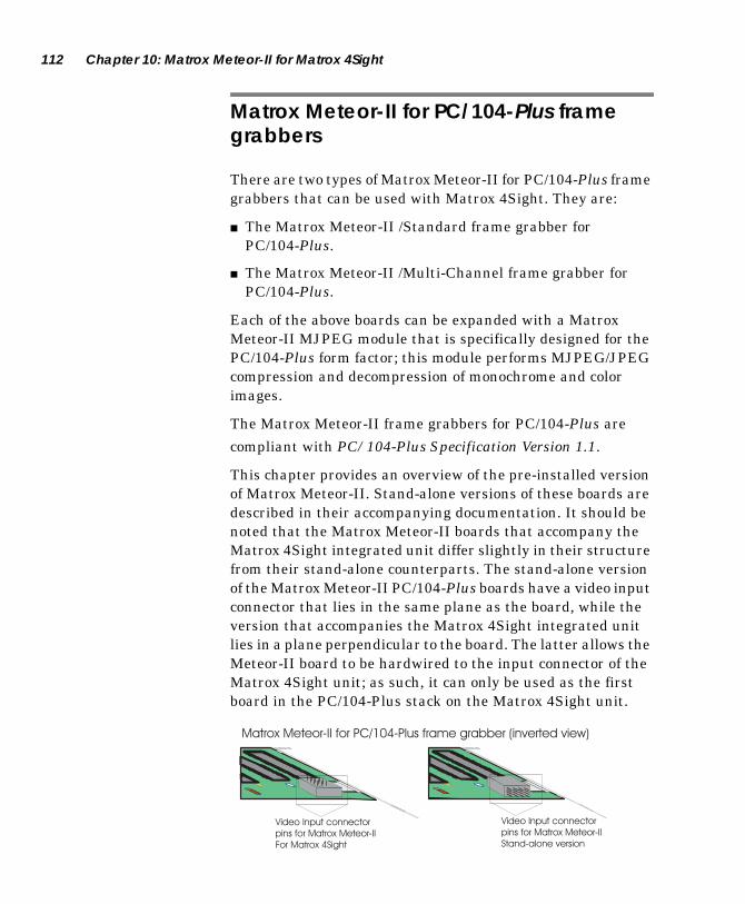
112 Chapter 10: Matrox Meteor-II for Matrox 4Sight
Matrox Meteor-II for PC/104-Plus frame grabbers
There are two types of Matrox Meteor-II for PC/104-Plus frame grabbers that can be used with Matrox 4Sight. They are:
■ The Matrox Meteor-II /Standard frame grabber for PC/104-Plus.
■ The Matrox Meteor-II /Multi-Channel frame grabber for PC/104-Plus.
Each of the above boards can be expanded with a Matrox Meteor-II MJPEG module that is specifically designed for the PC/104-Plus form factor; this module performs MJPEG/JPEG compression and decompression of monochrome and color images.
The Matrox Meteor-II frame grabbers for PC/104-Plus are
compliant with PC/104-Plus Specification Version 1.1.
This chapter provides an overview of the pre-installed version of Matrox Meteor-II. Stand-alone versions of these boards are described in their accompanying documentation. It should be noted that the Matrox Meteor-II boards that accompany the Matrox 4Sight integrated unit differ slightly in their structure from their stand-alone counterparts. The stand-alone version of the Matrox Meteor-II PC/104-Plus boards have a video input connector that lies in the same plane as the board, while the version that accompanies the Matrox 4Sight integrated unit lies in a plane perpendicular to the board. The latter allows the Meteor-II board to be hardwired to the input connector of the Matrox 4Sight unit; as such, it can only be used as the first board in the PC/104-Plus stack on the Matrox 4Sight unit.
Video Input connector
pins for Matrox Meteor-II
For Matrox 4Sight
Video Input connector
pins for Matrox Meteor-II
Stand-alone version
Matrox Meteor-II for PC/104-Plus frame grabber (inverted view)

Matrox Meteor-II /Standard grab section 113
Matrox Meteor-II /Standard grab section
The grab section of the Matrox Meteor-II /Standard board uses a video decoder to capture monochrome video in RS-170/CCIR format, and composite (CVBS) or component (Y/C) color video in NTSC/PAL format.
For the purpose of expediency the Matrox Meteor-II MJPEG module and the Matrox VIA will be discussed later in this chapter, since they apply to both Matrox Meteor-II’s available for Matrox 4Sight.
.
(4 Mbytes)
Gain Decoder
To video inputconnector
24
32
64
VID_IN2
VID_IN9
VID_IN1
VID_IN8
VID_IN3
VID_IN10
VID_IN4
VID_IN11
VID_IN5
VID_IN12
VID_IN6VID_IN7
LowPass
Filter
VIA SGRAM
Opto-coupler
Trigger
Host 32-bit PCI bus
12:1MUX MJPEG
Module
(optional)
Aux 2
2
{

114 Chapter 10: Matrox Meteor-II for Matrox 4Sight
Performance The video timing parameters supported by the Matrox Meteor-II /Standard board are as follows:
Input channels
Matrox Meteor-II /Standard for PC/104-Plus can switch between up to twelve independent composite or six Y/C video sources.
You can only acquire data from one video source at a time. You can use the MIL-Lite MdigChannel() command to switch between video sources (or channels).
Low-pass filterThe input low-pass filtering stage is used to limit high frequency noise and aliasing effects at the input of the decoder. The filter used on Matrox Meteor-II /Standard for PC/104-Plus is a single-order filter with a cutoff frequency of 6 MHz.
Video decoder
A multi-standard video decoder is used to convert analog monochrome video in RS-170/CCIR format, or composite (CVBS) or component (Y/C) video in NTSC/PAL format to digitized video. The decoder supports RGB 8:8:8 (24-bit), RGB 5:6:5, YUV 4:2:2, and YUV 4:1:1 output pixel formats. Note that YUV 4:2:2 output pixel formats are grabbed as YUYV.
CCIR 601 sampling rates
Square pixel sampling rates
NTSC PAL NTSC PAL
Field rate (Hz) 60 50 60 50
Pixel/line (Pixels) 858 864 780 944
Active pixel/line (Pixels) 720 720 640 768
Active lines/frame (Lines) 480 580 480 580
Pixel rate (MHz) 13.5 13.5 12.27 14.75
ADC sampling rate (MHz) 27 27 24.54 29.50
Line rate (KHz) 15.750 15.625 15.750 15.625

Matrox Meteor-II /Standard grab section 115
The video decoder also features automatic gain control (AGC). However, you can disable this feature (MIL-Lite MdigControl() with M_GRAB_AUTOMATIC_INPUT_GAIN set to M_DISABLE) and adjust the gain manually (MdigControl() with M_GRAB_INPUT_GAIN).
TriggerMatrox Meteor-II /Standard accepts an external trigger input which allows image acquisition to be synchronized to external events. The trigger is synchronous to the incoming video stream and it is received through an opto-coupler that helps isolate the rest of the circuitry from surges. Matrox Meteor-II /Standard operates in next valid frame/field mode. When in this mode, the digitizer waits for the next valid frame or field (as specified by the DCF file) before commencing the grab. This trigger mode functions in one of three ways:
■ Edge-triggered monoshot acquisition: The VIA (Video Interface Asic) waits for the rising/falling* edge to capture a single frame.
■ Edge-triggered continuous acquisition: The VIA waits for the rising/falling* edge to start a continous grab.
■ Level-sensitive "continuous" acquisition: The VIA grabs continuously while the level of the trigger is high/low*.
* The polarity of the active and inactive levels of the trigger signal are software programmable.
Trigger signals connected to the OPTOTRIG- and OPTOTRIG+ input pins, pass through an opto-coupler, a device that protects the board from outside surges; OPTOTRIG- is usually connected to the ground of the trigger source. The voltage difference across OPTOTRIG+ and OPTOTRIG- must be between 4.05 V and 9.16 V for logic high, and between -5.0 V and 0.8 V for logic low. Refer to Appendix D for the pinouts of these signals on your board.

116 Chapter 10: Matrox Meteor-II for Matrox 4Sight
User bits
Matrox Meteor-II /Standard supports four auxiliary user bits through the video input connector: two input and two output. These are available for controlling external events such as a strobe light. User bits are programmed using the MIL-Lite command MdigControl().
Matrox Meteor-II /Multi-Channel grab section
The grab section of the Matrox Meteor-II /Multi-Channel board captures monochrome or component-RGB video signals from standard and non-standard video sources.
.
VIA
LUT
3 256x8-bit
VID_IN1_1
VID_IN1_2
VID_IN2_1
VID_IN2_2
VID_IN3_2
SYNC_IN
VID_IN3_1
24
Low-pass
filters/Gain
Syncseparator
2:1MUX
2:1MUX
2:1MUX
4:1MUX
A/D
A/D
A/D
24
White
Black
White
Black
White
Black
SGRAM(4 Mbytes)
64
MJPEGModule
(optional)
24To videoinputconnector
PSG
TTL*Drivers
&Receivers
Clk inputClk output
HsyncVsync
TriggerExposure timer1Exposure timer2
Aux
Host 32-bit PCI bus
32
2
2{
TriggerOpto-
coupler

Matrox Meteor-II /Multi-Channel grab section 117
Performance The video timing parameters (including those for progressive scan) supported by the Matrox Meteor-II /Multi-Channel board are as follows:
*Note that the maximum number of pixels per line that MIL supports is:
Input channels
The Matrox Meteor-II /Multi-Channel frame grabber can switch between two RGB or six monochrome video sources. You can use the MIL-Lite MdigChannel() command to switch between video sources (or channels).
Low-pass filterThe input low-pass filtering stage is used to limit high frequency noise and aliasing effects at the input of the triple A/D converter. The filter used on Matrox Meteor-II /Multi-Channel is a 4th order Butterworth filter with a cutoff frequency of 10 MHz.
GainMatrox Meteor-II /Multi-Channel has adjustable gains. This allows you to optimize the video input signal range.
Max
Number of pixels / line (including sync and blanking) 4096*
Number of lines / frame (including sync and blanking) 4096*
Sampling rate (with external clock input, or in line-locking mode)
30 MSPS
PixelsLine
-------------- x Number of Lines 4 Mbytes≤

118 Chapter 10: Matrox Meteor-II for Matrox 4Sight
You can change the gain value using the MIL-Lite MdigControl() command. The supported gain factors are as follows:
Triple A/D converterA triple A/D converter with external reference generation and sync slicing is used for component RGB digitization. The converter can be operated at up to 30 MSPS.
In addition, the converter’s black and white reference levels can be adjusted individually. The black and white reference levels can be adjusted between 0.6 V to 1.6 V and 1.6 V to 2.6 V respectively, in increments of 10.23 mV (98 distinct adjustments).
Use the MIL-Lite MdigReference() command to set the black and white reference levels.
PSG
The Programmable Synchronization Generator (PSG) is responsible for managing all timing and synchronization signals.
Input video signal amplitude (excluding sync)
Total input video signal amplitude (including sync)
Required gain setting
MIL
0.0 V up to 0.5 V 0.0 - 0.7 Vpp 4 M_GAIN3
0.5 V up to 0.7 V 0.7 - 1.0 Vpp 2.8 (default) M_GAIN2
0.7 V up to 1.0 V 1.0 - 1.4 Vpp 2 M_GAIN1
1.0 V up to 1.5 V 1.4 - 2.1 Vpp 1.3 M_GAIN0
1.5 V up to 2.0 V 2.1 - 2.9 Vpp 1 M_GAIN4

Matrox Meteor-II /Multi-Channel grab section 119
Phase-locked loopThe high-performance, low-jitter phase-locked loop (PLL) uses frequency synthesis techniques to generate the clock signal, when necessary.
The PLL can use the following sources as a reference:
■ The on-board crystal oscillator.
■ The horizontal video synchronization signal supplied by the video source (line-locked mode).
When in line-locked mode and accepting a composite video signal, the PLL can synchronize to either serrated or block vertical synchronization signals.
■ The clock signal supplied by the video source (to generate a different clock).
When the input source supplies a sampling clock that does not require adjustment, the PLL is bypassed to avoid adding jitter to the supplied clock.
General synchronizationMatrox Meteor-II /Multi-Channel can operate in either slave or master mode.
Slave mode ■ In slave mode, the video source provides the synchronization information to Matrox Meteor-II /Multi-Channel. It can accept one of the following synchronization schemes:
❐ The video source encodes the synchronization signals on the analog video signal provided to the board.
❐ The video source supplies the horizontal and/or vertical synchronization signals separately in TTL format.
❐ The video source provides a composite synchronization signal in TTL format, separate from the analog video.
■ Synchronization information can be sent either with the video data, or on a separate analog synchronization channel.

120 Chapter 10: Matrox Meteor-II for Matrox 4Sight
Master mode ■ In master mode, Matrox Meteor-II /Multi-Channel generates (using the PSG) the horizontal and/or vertical (TTL) synchronization signals and supplies them to the video source. This allows the video source to synchronize to the board.
TriggerMatrox Meteor-II /Multi-Channel accepts an external trigger input which allows image acquisition to be synchronized to external events. The board can operate in one of two modes, and the selected mode is specified by the DCF.
Matrox Meteor-II /Multi-Channel can operate in next valid frame/field mode When in this mode, the digitizer waits for the next valid frame or field (as specified by the DCF file) before commencing the grab. This trigger mode functions in one of three ways:
■ Edge-triggered monoshot acquisition: The VIA (Video
Interface Asic) waits for the rising/falling1 edge to capture a single frame.
■ Edge-triggered continuous acquisition: The VIA waits for the rising/falling* edge to start a continous grab.
■ Level-sensitive "continuous" acquisition: The VIA grabs
continuously while the level of the trigger is high/low1.
Matrox Meteor-II /Multi-Channel can also operate in asynchronous reset mode. In this mode, the digitizer resets the camera to begin a new frame when the trigger signal is received.
Trigger signals connected to the OPTOTRIG- and OPTOTRIG+ input pins, pass through an opto-coupler, a device that protects the board from outside surges; OPTOTRIG- is usually connected to the ground of the trigger source. The voltage difference across OPTOTRIG+ and OPTOTRIG- must be between 4.05 V and 9.16 V for logic high, and between -5.0 V and 0.8 V for logic low. Refer to Appendix D for the pinouts of these signals on your board.
1. The polarity of the active and inactive levels of the trig-ger signal are software programmable.

Matrox Video Interface ASIC (VIA) 121
Lookup table (LUT)Matrox Meteor-II /Multi-Channel has three 256x8-bit input lookup tables (LUTs), allowing independent re-mapping of three 8-bit input streams.
The LUTs support RGB 8:8:8, RGB 5:6:5, and RGB 5:5:5 output pixel formats. LUTs are programmed using the MIL-Lite command, MdigLut().
User bitsMatrox Meteor-II /Multi-Channel supports four auxiliary TTL user bits through the video input connector: two input and two output. These are available for controlling external events such as a strobe light or PLC. User bits are programmed using the MIL-Lite command MdigControl().
Matrox Video Interface ASIC (VIA)
Each Matrox Meteor-II frame grabber for PC/104-Plus has a Matrox Video Interface ASIC (VIA). The VIA acts mainly as a bridge to the PCI bus. It uses 4 Mbytes of on-board SGRAM to store data until the PCI bus is ready to receive it.
Simultaneous data streams
Matrox VIA can manage up to two simultaneous data streams. For example:
■ It can grab into SGRAM, and concurrently transfer data between SGRAM and another PCI device.
■ It can perform PCI data transfers and concurrently permit the Host processor to access SGRAM.
Color planeseparation
Matrox VIA is capable of color plane separation of image input on two, three, or four 8-bit or 16-bit components (for example, RGB packed to RGB planar). This mechanism can be used to merge line segments from monochrome multi-tap cameras, connected to a Matrox Meteor-II /Multi-Channel frame grabber.

122 Chapter 10: Matrox Meteor-II for Matrox 4Sight
Matrox Meteor-II MJPEG Module
The optional Matrox Meteor-II MJPEG module performs real-time lossy and lossless MJPEG (interlaced and non-interlaced) compression and decompression of color and monochrome video. There are two versions of the Matrox Meteor-II MJPEG module available: PCI and PC/104-Plus. Matrox 4Sight is compatible with the PC/104-Plus version.
The Matrox Meteor-II MJPEG module supports lossy compression of RGB 8:8:8 and YUV 4:2:2 standard video, in continuous mode. The module also supports lossy and lossless compression of 8-bit monochrome images.
FPGA
Pixel DataInput/Output
VIA SGRAMInterface Port
BlockData
PixelInterface
HostInterface
CodeInterface
HostInterface
JPEGProcessorInterface
MemoryPort
Matrox Meteor-II MJPEG Module
HostInterface
Strip BufferMemory
8
8
8
16 SRAM(64Kbytes)
Color SpaceConverter
JPEGProcessor
Meteor-IIGrab PortInterface
MJPEG
24
ProgressivePath
248
64

Matrox Meteor-II MJPEG Module 123
Color Space Converter The Color Space Converter has two functions. During compression, it converts the incoming data for the JPEG processor; the data is reformatted from raster format into 8 x 8 pixel blocks and then passed back to the JPEG processor. The Color Space Converter’s second function is to convert RGB data into YUV format in order to reduce the processing time and the amount of data for compression.
During decompression, the 8 x 8 pixel blocks are reformatted into raster format, and in the case of RGB data, the Color Space Converter reconverts the compressed YUV data into RGB data.
JPEG Processor During compression, the JPEG Processor receives the 8 x 8 pixel blocks and compresses them according the JPEG standard. Both lossy and lossless formats are supported. During decompression, the JPEG Processor decompresses the data, and transfers the 8 x 8 pixel blocks to the Color Space Converter.
MJPEG FPGA The MJPEG FPGA controls the direction of compressed and decompressed data and generates control signals on the module. It implements a bus handshake with the VIA on the baseboard to access the SGRAM. The SGRAM on the baseboard is used to store the compressed data.
Encoding MJPEG During MJPEG (interlaced) compression, the baseboard grabs a field of data. This data enters the module through the Meteor-II grab port, and passes through the Color Space Converter, the JPEG Processor, and finally exits the module to the Host through the memory port on the MJPEG FPGA chip.
Host

124 Chapter 10: Matrox Meteor-II for Matrox 4Sight
Encoding JPEG During JPEG (non-interlaced) compression, the baseboard grabs an entire frame of data. This data enters the module through the memory port on the MJPEG FPGA chip and passes through the Color Space Converter. From there, JPEG compression follows the same path as MJPEG compression. Compressing an archived video stream is supported under JPEG compression.
Decoding During decompression, the data enters through the memory port on the MJPEG FPGA chip, and passes through the JPEG processor, the Color Space Converter, and finally exits through the Matrox Meteor-II grab port.
❖ Due to a hardware limitation, the MJPEG module on the Matrox Meteor-II /Standard cannot decompress JPEG (non-interlaced) compressed data; decompression of JPEG data will be performed by the Host.
Host
Host

Appendix A: Troubleshooting
This appendix provides solutions to potential problems.

126 Appendix A: Troubleshooting
What to do if you have a problem
If you experience problems using Matrox 4Sight, please:
■ Check that all cables are properly connected.
■ Review this manual, including the rest of this chapter, to see whether your problem is addressed here.
■ Check whether your problem is discussed on the Matrox Imaging web site.
If the above solutions do not work, contact your local Matrox representative, Matrox sales, or Matrox customer support. See the Customer support section at the back of this manual for more information.
Common problems and solutions
Monitor problems ☛ My monitor is blank (or it has shades or spots of gray and
white).
■ Make sure that Matrox 4Sight and your monitor are turned on.
■ Check that your monitor cable is properly connected.
■ Make sure the brightness and contrast controls of your monitor are set correctly.
■ Set your monitor’s input impedance switches (if any) to 75 ohms for the red, green, and blue inputs. Set the synchronization switches to high impedance and external sync mode. If there is a Digital/Analog switch on your monitor, set it to Analog.
☛ When I run an application, there is no picture on my video display. The monitor is blank.
The application you are running might be attempting to use a resolution that is not supported by your monitor. Check your monitor’s manual for supported resolutions.

Common problems and solutions 127
☛ The colors are wrong.
Incorrect colors indicate that either the cabling (for monitors that do not have a built-in cable) or the monitor impedance is incorrect.
■ Make sure your monitor’s input impedance switches (if any) are set to 75 ohms for the red, green, and blue inputs.
■ Check that your monitor cable is properly connected.
☛ The display is not centered.
Adjust the centering control of your monitor (refer to your monitor’s manual for more information).
☛ The picture quality is poor, with a dim picture, poor contrast, and poor sharpness.
■ Adjust the brightness, sharpness, and contrast controls of your monitor (refer to your monitor’s manual for more information).
■ Check that your monitor cable is properly connected.
■ Make sure your monitor’s input impedance switches (if any) are set to 75 ohms for the red, green, and blue inputs.
☛ The picture is broken up, with bad horizontal sync; in other words, it rolls, jitters, or blinks.
■ Set the synchronization switches to high impedance and external sync mode. If this does not solve the problem, your monitor might need horizontal setting adjustments, or it might be defective. Refer to your monitor’s manual.
■ Ensure that the resolution you specified is valid for your monitor.
☛ Memory has been added but the change is not registered by your machine.
■ Ensure that your RAM is compatible with Matrox 4Sight and that it has been properly installed.
■ If you are running Windows NT Workstation and you have previously installed MIL or Inspector on your hard drive, you can use the MILConfig utility to handle the amount of DMA (physically contiguous, non-pageable) memory on your unit.

128 Appendix A: Troubleshooting
Alternatively, you can uninstall your Matrox software before adding memory and reinstall the software after the memory has been added. One of these procedures is necessary due to the fact that these Matrox software packages reserve DMA memory for grabbing.
Note that when running Windows NT Embedded, the NTConfig utility will automatically recognize and handle any additional memory. However, you can also use the MILConfig utility to change the amount of reserved DMA memory from the factory default value of 3.5 Mbytes.
☛ Read/write errors occur when using the DiskOnChip.
■ Reinstall the DiskOnChip image file and start over.
■ Call Matrox for information concerning which M-Systems products can be used to replace your current DiskOnChip.
☛ Mismatched network settings resulting in very slow communication.
■ Determine the server setting and configure Matrox 4Sight to match these networks settings.

Appendix B: NTConfig Windows NT Embedded registry
This appendix deals with NTConfig command line options and manually changing registry settings.

130 Appendix B: NTConfig Windows NT Embedded registry
Windows NTConfig command line options
NTConfig is a utility included in Windows NT Embedded by Matrox. The purpose of NTConfig is to allow you to easily alter several registry entries and perform a number of common tasks using command line options. Altering registry entries will be discussed later in this chapter. The command line for NTConfig is:
NTConfig [/REBOOT] [/SHUTDOWN] [/DMACHECK] [/MEM] [/AUTOPOPUP]
NTConfig will only allow the modification of settings that can be changed according to a user’s rights. Fields that cannot be modified will remain grey. Note that some fields can only be modified by accounts that have administrative rights.
The following is a list of command line options for NTConfig:
/REBOOT
When calling NTConfig with the /Reboot option, the Matrox 4Sight unit unconditionally reboots; the standard NTConfig dialog box is not displayed. Windows NT Embedded starts a shutdown procedure and, after the shutdown, automatically reboots the unit. All other command line options are ignored when this option is used. This option is useful to reboot remotely, if you have written the appropriate applications to do so.
/SHUTDOWN
When calling NTConfig with the /Shutdown option, the Matrox 4Sight unit unconditionally shuts down the Matrox 4Sight unit; the standard NTConfig dialog box is not displayed. When Windows NT Embedded completes the shutdown procedure, the unit will display the Windows NT Embedded ‘Shutdown Computer’ dialog box. At this point, you can power down the unit, or press the Restart button in this dialog to automatically reboot the Matrox 4Sight unit. All other command line options are ignored when this option is used. This option is useful for remote shutdown of your Matrox 4Sight unit, if you have written the appropriate applications to do so.

Windows NTConfig command line options 131
/DMACHECK
When calling NTConfig with the /DMACheck option, NTConfig determines the amount of memory installed in the Matrox 4Sight unit. In addition, it validates and corrects other memory-related parameters. The standard NTConfig dialog box is not displayed.
The memory-related parameters are considered valid when the total amount of physical memory minus the total amount of video memory reserved at boot time, minus the total amount of DMA memory reserved by MIL, minus the total amount of memory available to Windows NT Embedded equals 0. That is:
PhysicalMem - VideoMem – DMAMem – AvailMem = 0
If this equation is unbalanced, NTConfig will adjust the DMA memory parameter accordingly. You will be advised that the computer will reboot immediately so that the adjustments will take effect. This command is useful for adjusting the amount of memory available to the operating system if physical memory (RAM) is added or removed while DMA memory is reserved by MIL
/MEM
When calling NTConfig with the /Mem option, NTConfig performs the same operations as /DMACHECK. However, before validating and correcting memory-related parameters, it reports these parameters.
/AUTOPOPUP
When calling NTConfig with the /Autopopup option, NTConfig checks the registry to determine if the automatic popup feature is enabled. If so, it displays the standard NTConfig dialog box; otherwise it does nothing. This option is used at bootup time to determine if the standard NTConfig dialog box should be displayed. You can disable the automatic popup feature using the checkbox in the standard NTConfig dialog box.

132 Appendix B: NTConfig Windows NT Embedded registry
Manually configuring the Windows NT Embedded registry
This section discusses how to manually change the Windows NT Embedded registry entries controlled by Matrox NTConfig and a few other important registry entries. We recommend using NTConfig to alter those entries controlled by NTConfig; this method is much easier than writing directly to the registry database.
If you choose to write directly in the registry database use Regedit, the registry database editor, to modify keys of the registry database directly. Exercise caution when altering the database with this method because simple mistakes can easily lead to a configuration that corrupts Windows NT Embedded.
Network componentsNote that the registry keys relevant to DAVICOM are only relevant to Matrox 4Sight units that have a DAVICOM Ethernet controller. Registry keys relevant to INTEL are only relevant to Matrox 4Sight units that have an INTEL Ethernet controller. To identify which Ethernet controller is installed on the Matrox 4Sight unit, look at the NTConfig dialog box under the “Enable all network devices and drivers” check box. The check box will identify the Ethernet controller as soon as NTConfig can detect it.

Manually configuring the Windows NT Embedded registry 133
Enable or disable network
Manually change one key in the registry to enable/disable the network drivers and components of your Matrox 4Sight unit under Windows NT Embedded. The key has been initialized to a default value. The enable/disable setting can be found in the following registry key:
Registry Keys (INTEL Ethernet)
Setup
HKEY_LOCAL_MACHINE\ SYSTEM\ CurrentControlSet\ Hardware Profiles\ Current\System\ CurrentControlSet\ Enum\ROOT\ LEGACY_E100E\ 0000\CSConfigFlags
Set DWORD to 0 or 1. Use 1 to disable network components.
Registry Keys (DAVICOM Ethernet)
Setup
HKEY_LOCAL_MACHINE\ SYSTEM\ CurrentControlSet\ Hardware Profiles\ Current\System\ CurrentControlSet\ Enum\ROOT\ LEGACY_DAVICOM\ 0000\CSConfigFlags
Set DWORD to 0 or 1. Use 1 to disable network components.

134 Appendix B: NTConfig Windows NT Embedded registry
Static or dynamic IP
Manually change some keys in the registry to set the IP allocation mode and static IP address of your Matrox 4Sight unit under Windows NT Embedded. These keys have been initialized to default values and are available to all users on the computer.
The IP allocation mode and static IP address setting can be found in the following registry keys:
Registry Keys (INTEL Ethernet)
Setup
HKEY_LOCAL_MACHINE\ SYSTEM\CurrentControlSet\ Services\E100E1\ Parameters\TcpIp\ IPAddress
Pass a multi-string character-coded address. For example, for the address 192.168.54.109, pass:0x31 0x39 0x32 0x20 0x31 0x36 0x38 0x20 0x35 0x34 0x20 0x31 0x30 0x39 0x00 0x00.
HKEY_LOCAL_MACHINE\ SYSTEM\CurrentControlSet\ Services\E100E1\ Parameters\TcpIp\ SubnetMask
Pass a multi-string character-coded address. For example, for the subnet 255.255.255.0, pass:0x32 0x35 0x35 0x20 0x32 0x35 0x35 0x20 0x32 0x35 0x35 0x20 0x30 0x00 0x00.
HKEY_LOCAL_MACHINE\ SYSTEM\CurrentControlSet\ Services\E100E1\ Parameters\TcpIp\ DefaultGateway
Pass a multi-string character-coded address. For example, for the gateway 192.168.54.1, pass:0x31 0x39 0x32 0x20 0x31 0x36 0x38 0x20 0x35 0x34 0x20 0x31 0x00 0x00.

Manually configuring the Windows NT Embedded registry 135
HKEY_LOCAL_MACHINE\ SYSTEM\CurrentControlSet\ Services\E100E1\ Parameters\TcpIp\ EnableDHCP
Set DWORD to 0 or 1. Use 1 to activate the DHCP.
\SYSTEM\CurrentControlSet\ Services\Tcpip\Parameters\ Domain
Set STRING to a string representing the machine domain name.
Registry Keys (DAVICOM Ethernet)
Setup
HKEY_LOCAL_MACHINE\ SYSTEM\CurrentControlSet\ Services\DAVICOM2\ Parameters\TcpIp\ IPAddress
Pass a multi-string character-coded address. For example, for the address 192.168.54.109, pass:0x31 0x39 0x32 0x20 0x31 0x36 0x38 0x20 0x35 0x34 0x20 0x31 0x30 0x39 0x00 0x00.
HKEY_LOCAL_MACHINE\ SYSTEM\CurrentControlSet\ Services\DAVICOM2\ Parameters\TcpIp\ SubnetMask
Pass a multi-string character-coded address. For example, for the subnet 255.255.255.0, pass:0x32 0x35 0x35 0x20 0x32 0x35 0x35 0x20 0x32 0x35 0x35 0x20 0x30 0x00 0x00.
HKEY_LOCAL_MACHINE\ SYSTEM\CurrentControlSet\ Services\DAVICOM2\ Parameters\TcpIp\ DefaultGateway
Pass a multi-string character-coded address. For example, for the gateway 192.168.54.1, pass:0x31 0x39 0x32 0x20 0x31 0x36 0x38 0x20 0x35 0x34 0x20 0x31 0x00 0x00.

136 Appendix B: NTConfig Windows NT Embedded registry
Ethernet connection type
Manually change one key in the registry to set the Ethernet connection type required by your LAN. This key has been initialized to a default value and is available to all users on the computer. The connection type setting can be found in the following registry key:
HKEY_LOCAL_MACHINE\ SYSTEM\CurrentControlSet\ Services\DAVICOM2\ Parameters\TcpIp\ EnableDHCP
Set DWORD to 0 or 1. Use 1 to activate the DHCP.
\SYSTEM\CurrentControlSet\ Services\Tcpip\Parameters\ Domain
Set STRING to a string representing the machine domain name.
Registry Keys (INTEL Ethernet)
Setup
HKEY_LOCAL_MACHINE\ SYSTEM\CurrentControlSet\ Services\E100E1\ Parameters\ Speed
Set DWORD to one of the following values:0 for auto-negotiation; maximum output. 10 for forced without advertising 10 Mbits100 for forced without advertising 100 Mbits
HKEY_LOCAL_MACHINE\ SYSTEM\CurrentControlSet\ Services\E100E1\Parameters\ ForceDpx
Set DWORD to one of the following values:0 for auto-negotiation; maximum output1 for forced without advertising half duplex2 for forced without advertising full duplex

Manually configuring the Windows NT Embedded registry 137
Computer name
Manually change some keys in the registry to set the computer name required by your LAN. This key has been initialized to a default value and is available to all users on the computer. The computer name setting can be found in the following keys:
Registry Keys (DAVICOM Ethernet)
Setup
HKEY_LOCAL_MACHINE\ SYSTEM\ CurrentControlSet\ Services\DAVICOM2\ Parameters\ ConnectionType
Set DWORD to one of the following values:0 for auto-negotiation; maximum output.Forced with advertising:2 for 10 Mbits half duplex3 for 10 Mbits full duplex8 for 100 Mbits half duplex9 for 100 Mbits full duplex
Forced without advertising:10 for 10 Mbits half duplex11 for 10 Mbits full duplex12 for 100 Mbits half duplex13 for 100 Mbits full duplex
Registry Keys Setup
HKEY_LOCAL_MACHINE\ SYSTEM\CurrentControlSet\ Control\ComputerName\ ComputerName\ ComputerName
Set STRING to a string representing the computer name.
HKEY_LOCAL_MACHINE\ SYSTEM\CurrentControlSet\ Control\ComputerName\ ActiveComputerName\ ComputerName
Set STRING to a string representing the active computer name.
HKEY_LOCAL_MACHINE\ SYSTEM\CurrentControlSet\ Services\Tcpip\Parameters\ Hostname
Set STRING to a string representing the computer name of the development computer.

138 Appendix B: NTConfig Windows NT Embedded registry
Display components
Manually change some keys in the registry to change the display driver resolution of your Matrox 4Sight unit. These keys have been initialized to a default value. The display resolution setting can be found in the following registry keys:
Registry Keys Setup
HKEY_LOCAL_MACHINE\ SYSTEM\CurrentControlSet\ Hardware Profiles\Current\ SYSTEM\CurrentControlSet \Services\GX\Device0\ DefaultSettings.Xresolution
Set DWORD to one of the following X resolution values: 640, 800, 1024, 1280.
HKEY_LOCAL_MACHINE\ SYSTEM\CurrentControlSet\ Hardware Profiles\Current\ SYSTEM\CurrentControlSet \Services\GX\Device0\ DefaultSettings.Yresolution
Set DWORD to one of the following Y resolution values: 480, 600, 768, 1024.
HKEY_LOCAL_MACHINE\ SYSTEM\CurrentControlSet\ Hardware Profiles\Current\ SYSTEM\CurrentControlSet \Services\GX\Device0\ DefaultSettings.Vrefresh
Set DWORD to one of the following vertical refresh rate values: 60, 70, 72, 75.
HKEY_LOCAL_MACHINE\ SYSTEM\CurrentControlSet\ Hardware Profiles\Current\ SYSTEM\CurrentControlSet \Services\GX\Device0\ DefaultSettings.BitsPixel
Set DWORD to one of the following bits per pixel values: 8,16.

Manually configuring the Windows NT Embedded registry 139
The following is a list of available display modes:
Auto-logon feature
By default, the auto-logon feature is enabled. To disable the auto-logon feature or change its default settings, use the NTConfig utility and select the ‘Auto Logon Settings...’. Alternatively, you can manually change some of the following keys in the registry:
640 x 480 256 colors at 60, 72, or 75 Hertz
800 x 600 256 colors at 60, 72, or 75 Hertz
1024 x 768 256 colors at 60, 70, or 75 Hertz
1280 x 1024 256 colors at 60 or 75 Hertz
640 x 480 65536 colors at 60, 72, or 75 Hertz
800 x 600 65536 colors at 60, 72, or 75 Hertz
1024 x 768 65536 colors at 60, 70, or 75 Hertz
Registry Keys Setup
HKEY_LOCAL_MACHINE\ SOFTWARE\Microsoft\ WindowsNT\ CurrentVersion\ Winlogon\AutoAdminLogon
Set DWORD to 0 or 1. Use 1 to activate the auto-logon.
\SOFTWARE\Microsoft\ WindowsNT\CurrentVersion\ Winlogon\ DefaultDomainName
Set STRING to a string representing the default domain name on which to logon.
\SOFTWARE\Microsoft\ WindowsNT\CurrentVersion\ Winlogon\DefaultUserName
Set STRING to a string representing the default user name with which to logon.
\SOFTWARE\Microsoft\ WindowsNT\CurrentVersion\ Winlogon\DefaultPassword
Set STRING to a string representing the password of the default user name with which to logon.

140 Appendix B: NTConfig Windows NT Embedded registry
Shell command lineThe shell command line is initialized to a default value. This shell command is executed each time Windows NT Embedded boots. To change its default settings, manually change the following key of the registry:
Product ID, Owner, and Organization
The following registry keys identify the owner of the computer. Change these keys to identify the owner of the computer.
Registry Keys Setup
HKEY_LOCAL_MACHINE\ SOFTWARE\Microsoft\ WindowsNT\CurrentVersion\ Winlogon\Shell
Set STRING to string representing the default shell command line.
Registry Keys Setup
HKEY_LOCAL_MACHINE\ SOFTWARE\Microsoft\ WindowsNT\CurrentVersion\ ProductId
Set STRING to a string representing the Windows NT product ID.
\SOFTWARE\Microsoft\ WindowsNT\CurrentVersion\ RegisteredOwner
Set STRING to a string representing the Windows NT registered owner.
\SOFTWARE\Microsoft\ WindowsNT\CurrentVersion\ RegisteredOrganization
Set STRING to a string representing the Windows NT registered owner organization.

Manually configuring the Windows NT Embedded registry 141
Keyboard layoutThe following registry key changes the keyboard layout. Manually change the setting of this key:
Auto-popup feature
The following registry key enables/disables the auto-popup feature of NTConfig. Manually change the setting of this key:
Registry Keys Setup
HKEY_CURRENT_USER\ Keyboard Layout\Preload\1
Set STRING to one of the following Windows NT keyboard layout ID strings:
“00000409” for an English US keyboard.
“0000040C” for a French standard keyboard.
“00000407” for a German standard keyboard.
Registry Keys Setup
HKEY_LOCAL_MACHINE\ SOFTWARE\Matrox\ NTConfig\Autopopup
Set DWORD to 0 or 1. Use 0 to deactivate the auto-popup feature.

142 Appendix B: NTConfig Windows NT Embedded registry
Joining a domain
To join a domain on a LAN, a special JoinDomR service must be used. The join operation can be done when activating this service after having set some of the join domain parameters such as the domain name to join, the user account to add, and the password of the user account that has been added.
Registry Keys Setup
HKEY_LOCAL_MACHINE\ SYSTEM\CurrentControlSet\ Control\ComputerName\ JoinDomainOnNextBoot\ DomainName
Set STRING to represent the domain name to join.
HKEY_LOCAL_MACHINE\ SYSTEM\CurrentControlSet\ Control\ComputerName\ JoinDomainOnNextBoot\ UserName
Set STRING to represent the user account that will add the machine on the domain name.
HKEY_LOCAL_MACHINE\ SYSTEM\CurrentControlSet\ Control\ComputerName\ JoinDomainOnNextBoot\ Password
Set STRING to represent the password of the user account that will add the machine on the domain name.
HKEY_LOCAL_MACHINE\ SYSTEM\CurrentControlSet\ Services\JoinDomR\Start
Set DWORD to 0 or 4.Use 4 to keep the machine off a domain. Use 0 to start the JoinDomR service and join the domain name.

Manually configuring the Windows NT Embedded registry 143
Choosing an IDE driverTo select which driver to use as the IDE driver. Only one of two drivers will be activated. Activating the ATAPI driver will lead to a normal data transfer rate to IDE devices. Activating the UDMA driver (OEMSCSI driver) will lead to a higher data transfer rate to IDE devices. Deactivating both of them will lead to an unbootable Windows NT Embedded unit.
Auxiliary I/O and other devicesWhen programming the interrupt line of the Auxiliary I/O device, one must ensure that no other driver can conflict with the selected interrupt line. These registry keys with the corresponding interrupt line will help to disable the conflicting driver to let the Auxiliary I/O device to use its selected interrupt line.
Registry Keys Setup
HKEY_LOCAL_MACHINE\ SYSTEM\CurrentControlSet\ Services\atapi\Start
Set DWORD to 0 or 4. Use 4 to deactivate the driver. Use 0 to activate the ATAPI driver.
HKEY_LOCAL_MACHINE\ SYSTEM\CurrentControlSet\ Services\oemscsi\Start
Set DWORD to 0 or 4. Use 4 to deactivate the driverUse 0 to activate the UDMA driver
Registry Keys (DAVICOM Ethernet)
Setup Notes
HKEY_LOCAL_MACHINE\ SYSTEM\ CurrentControlSet\ Services\Serial\Start
Set DWORD to 0 or 4.Use 4 to deactivate the driver.Use 0 to activate the Serial ports driver.
To be used when the Auxiliary I/O device is mapped to interrupt line 3 or 4 (IRQ 3 or IRQ 4).
HKEY_LOCAL_MACHINE\ SYSTEM\ CurrentControlSet\ Services\mgxsb16\Start
Set DWORD to 0 or 4.Use 4 to deactivate the driver.Use 0 to activate the Sound port driver.
To be used when the Auxiliary I/O device is mapped to interrupt line 5 (IRQ 5).

144 Appendix B: NTConfig Windows NT Embedded registry
HKEY_LOCAL_MACHINE\ SYSTEM\ CurrentControlSet\ Services\parallel\Start
Set DWORD to 0 or 4.Use 4 to deactivate the driver.Use 0 to activate the Parallel port driver.
To be used when the Auxiliary I/O device is mapped to interrupt line 7 (IRQ 7).
HKEY_LOCAL_MACHINE\ SYSTEM\ CurrentControlSet\ Services\corona\Start
Set DWORD to 0 or 4.Use 4 to deactivate the driver.Use 0 to activate the Meteor-II driver.
To be used when the Auxiliary I/O device is mapped to interrupt line 9 (IRQ 9).
HKEY_LOCAL_MACHINE\ SYSTEM\\ CurrentControlSet\\ Services\\DAVICOM\ Start
Set DWORD to 0 or 4.Use 4 to deactivate the driver.Use 0 to activate the Davicom Ethernet driver
DAVICOM ETHERNET ONLY.To be used when the Auxiliary I/O device is mapped to interrupt line 10 (IRQ 10).
HKEY_LOCAL_MACHINE\ SYSTEM\\ CurrentControlSet\\ Services\\E100E\Start
Set DWORD to 0 or 4.Use 4 to deactivate the driver.Use 0 to activate the Intel Ethernet Driver.
INTEL ETHERNET ONLY.To be used when the Auxiliary I/O device is mapped to interrupt line 10 (IRQ 10).
HKEY_LOCAL_MACHINE\ SYSTEM\ CurrentControlSet\ Services\mtx1394\Start
Set DWORD to 0 or 4.Use 4 to deactivate the driver.Use 0 to activate the Meteor-II 1394 driver.
To be used when the Auxiliary I/O device is mapped to interrupt line 11 (IRQ 11).
HKEY_LOCAL_MACHINE\ SYSTEM\ CurrentControlSet\ Services\MF1394core\ Start
Set DWORD to 0 or 4.Use 4 to deactivate the driver.Use 0 to activate the Meteor-II 1394 low level driver.
To be used then the Auxiliary I/O device is mapped to interrupt line 11 (IRQ 11).

Manually configuring the Windows NT Embedded registry 145
Machine name check feature
The following registry key changes the machine name check feature of NTConfig to enable or disable. When enabled, NTConfig checks if the user has changed the machine name at least once to a value different than the default one set at the factory. Manually change the setting of this key:
Registry Keys Setup
HKEY_LOCAL_MACHINE\ SOFTWARE\Matrox\ NTConfig\ MachineNameChanged
Set DWORD to 0 or 1. Use 0 to activate the machine name check feature.

146 Appendix B: NTConfig Windows NT Embedded registry
Appendix C: BIOS reference
This chapter describes the BIOS Setup program. It also lists BIOS error messages and diagnostic codes.

148 Appendix C: BIOS reference
Upgrading the BIOS of the Matrox 4Sight
On the Matrox 4Sight CD, the \BIOS folder contains the latest release of the Matrox 4Sight BIOS and the utility to write the BIOS on the Matrox 4Sight unit. This utility should be run from a DOS-compatible operating system. One method to verify the version of the BIOS installed on a Matrox 4Sight unit is to look at the upper left corner of the display while doing a cold boot of the Matrox 4Sight. It will state a version stamp similar to FS-A.BB.CCC.
The method to find the version of the BIOS file on the Matrox 4Sight CD is from the file name: fsabbccc.bin.
If the version stamp of the Matrox 4Sight unit is less recent than the Matrox 4Sight CD BIOS file, we recommend updating to the newer version from the Matrox 4Sight CD. To update the BIOS, follow these steps:
1. Using Windows NT Embedded or Windows NT Workstation, connect to a shared CD-ROM drive on a development PC that will contain the Matrox 4Sight CD.
2. Copy the \BIOS\FSABBCCC.BIN file and \BIOS\FLASHROM.COM file from the Matrox 4Sight CD to the Matrox 4Sight’s C:\ root folder.
3. Using Embedded-DOS or MS-DOS on the Matrox 4Sight unit, type the following command at the prompt: FLASHROM FSABBCCC.BIN.
4. Power down the Matrox 4Sight unit.
5. Power up the Matrox 4Sight unit.
6. Immediately enter the BIOS setup screen following the methods as listed below and select the Reset CMOS to factory defaults from the main options menu.

Upgrading the BIOS of the Matrox 4Sight 149
Note, once the BIOS has been upgraded, you can use the Basic CMOS Configuration subscreen to reset the time and date on the Matrox 4Sight unit as described below. Alternatively, while operating under Embedded-DOS, you can set the time and date as follows:
1. Open a command prompt window.
2. Type time after the C:\...> prompt and press Enter.
3. The unit will respond with the current time in memory and prompt you to enter the new time.
4. If the current time is correct, press Enter.
5. To change the time, enter it using the hour:minute 24-hour format.
To change the calendar date:
1. Open a command prompt window.
2. Type date at the C:\...> prompt and press Enter.
3. The unit will respond with the current date in memory and prompt you to enter the new date.
4. If the current date is correct, press Enter.
5. To change the date, enter it using the month-date-year calendar format.

150 Appendix C: BIOS reference
The BIOS Setup program
The BIOS Setup program allows you to modify certain hardware settings. The default settings are suitable in most cases, but under some circumstances, you might need to change them.
Note that configuration settings are stored in CMOS memory and backed up by a battery.
Entering the Setup program
To enter the Setup program, turn on Matrox 4Sight and press <Del>. You only have a few moments to press <Del> before the boot-up process continues.
When you enter the Setup program, you will be presented with the following options:
■ Basic CMOS Configuration
■ Advanced Configuration
■ Reset CMOS to Last Known Values
■ Reset CMOS to factory defaults
■ Write to CMOS and Exit
■ Exit without changing CMOS
Choose among the above options by using the Up or Down arrow keys and pressing <Enter>. The first two options bring up a subscreen where various fields allow you to modify the Matrox 4Sight BIOS configuration. After making changes in the subscreens, you can choose among the last four options.
The following sections describe the fields in each subscreen. To make changes or move around these subscreens, refer to the instructions given at the bottom of the subscreen.

Basic CMOS Configuration subscreen 151
Basic CMOS Configuration subscreen
Date and time section■ Date:
This field displays and sets the calendar date.
■ Time:
This field displays and sets the time.
Keyboard options section■ Typematic Delay:
This field sets the time to wait before starting to repeat a keyboard character that is held down.
Options:
❐ 250 ms (default)
❐ 500 ms
❐ 750 ms
❐ 1000 ms
❐ Disabled (no repeat)
■ Typematic Rate:
This field sets the rate at which to repeat a keyboard character when it is held down. Options are 6 characters per second (cps) to 30 cps (default).
MEMORY section■ Base:
This field reports the amount of base memory. This value will be 640 KB.
■ Ext:
This field reports the amount of extended memory available to the unit, after video memory has been reserved.
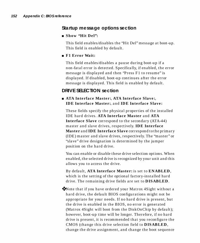
152 Appendix C: BIOS reference
Startup message options section■ Show “Hit Del”:
This field enables/disables the “Hit Del” message at boot-up. This field is enabled by default.
■ F1 Error Wait:
This field enables/disables a pause during boot-up if a non-fatal error is detected. Specifically, if enabled, the error message is displayed and then “Press F1 to resume” is displayed. If disabled, boot-up continues after the error message is displayed. This field is enabled by default.
DRIVE SELECTION section■ ATA Interface Master:, ATA Interface Slave:,
IDE Interface Master:, and IDE Interface Slave:
These fields specify the physical properties of the installed IDE hard drives. ATA Interface Master and ATA Interface Slave correspond to the secondary (ATA-44) master and slave drives, respectively. IDE Interface Master and IDE Interface Slave correspond to the primary (IDE) master and slave drives, respectively. The “master” or “slave” drive designation is determined by the jumper position on the hard drive.
You can enable or disable these drive selection options. When enabled, the selected drive is recognized by your unit and this allows you to access the drive.
By default, ATA Interface Master: is set to ENABLED, which is the setting of the optional factory-installed hard drive. The remaining drive fields are set to DISABLED.
❖ Note that if you have ordered your Matrox 4Sight without a hard drive, the default BIOS configurations might not be appropriate for your needs. If no hard drive is present, but the drive is enabled in the BIOS, no error is generated (Matrox 4Sight will boot from the DiskOnChip by default); however, boot-up time will be longer. Therefore, if no hard drive is present, it is recommended that you reconfigure the CMOS (change this drive selection field to DISABLED, change the drive assignment, and change the boot sequence

Basic CMOS Configuration subscreen 153
order). If you subsequently install a hard drive, again you should change the appropriate fields in the CMOS setup of the BIOS.
DRIVE ASSIGNMENT section■ Drive A:
This field specifies the size/capacity of the floppy drive. Options:
❐ None (default)
❐ 360 KB, 5.25”
❐ 1.2 MB, 5.25”
❐ 720 KB, 3.5”
❐ 1.44 MB, 3.5”
❐ 2.88 MB, 3.5”
■ Drive 1, Drive 2, and Drive 3:
These fields map the installed hard drives to drive numbers. The drive numbers are associated with drive letters according to the boot sequence specified in the Boot Order Sequence section. Note that by default the drive numbers correspond to the DOS operating system’s drive letter assignments in alphabetic order. Options:
❐ None (You can purchase Matrox 4Sight without a hard drive).
❐ IDE Master
❐ IDE Slave
❐ ATA Master
❐ ATA Slave
By default, Drive 1 is set to ATA Master while the remaining drive numbers are not assigned since there is usually only one factory-installed hard drive on Matrox 4Sight (if any). Only enabled drives (drives from the Drive Selection section that are enabled) are allowed. Note that if no hard drive is present, but the drive is enabled in the BIOS, no error is generated (Matrox 4Sight will boot from the

154 Appendix C: BIOS reference
DiskOnChip by default); however, boot-up time will be longer. Therefore, if no hard drive is present, it is recommended that you reconfigure the CMOS and set this field in the BIOS to None.
BOOT ORDER section ■ Boot 1st:, Boot 2nd:, and Boot 3rd:
These fields specify the boot sequence. That is, Matrox 4Sight will first search for an operating system on the drive specified by Boot 1st:, then search the drive (or load the operating system) specified by Boot 2nd:, and then search the drive (or load the operating system) specified by Boot 3rd:.
The drive options are:
❐ None
❐ Drive A:
❐ Drive 1
❐ Drive 2
❐ Drive 3
❐ D.O.C. (DiskOnChip)
The default setting for Boot 1st: is D.O.C. and for Boot 2nd: is Drive 1. Other fields are not set. The D.O.C. option is only available for the Boot 1st: field. Drive A is not assigned a boot field by default; however, you can assign it to the Boot 1st field.
Miscellaneous section■ Video Memory:
This field allows you to reserve specific amounts of video memory from the available external memory. Once you reserve video memory, it is no longer counted as available external memory. To determine the total available external memory that remains, subtract the amount of video display memory you allocated from the amount of processing memory.

Basic CMOS Configuration subscreen 155
❖ If, based on the specified display resolution and pixel depth, you have not reserved sufficient video memory for the display driver, an error will be generated.
Options:
❐ 1.5 Mbytes
❐ 2.5 Mbytes
❐ 3.5 Mbytes (default)
❐ 4.5 Mbytes
■ Boot Method:
This field specifies whether to use the boot sector to search for an operating system during boot-up, or whether to fetch the Windows CE operating system file named nk.bin.
Options:
❐ Boot Sector (default)
❐ Windows CE
■ Device List:
This field enables/disables the listing of installed PCI devices and their resources, before starting the operating system. The default setting is disabled.
■ Fast Boot:
This field enables/disables the RAM count option during a boot process. When set to Enable, no RAM count is displayed on screen. This speeds up the boot process. When set to Disable, the RAM count is displayed on screen.
Options:
❐ Disable (default)
❐ Enable

156 Appendix C: BIOS reference
Advanced Configuration subscreen
MISCELLANEOUS OPTIONS section■ Memory Speed Setting:
This field specifies the operating speed for the National
Semiconductor® Geode™ GXLV external memory interface. Options:
■ Wake Option:
This field specifies the state of Matrox 4Sight after a power interruption/failure has occurred. The Stay OFF option will leave Matrox 4Sight off when power resumes.
If the Power-ON option has been enabled prior to a power interruption/failure, Matrox 4Sight will be turned on when power resumes.
Options:
❐ Stay OFF (default)
❐ Power-ON
■ Parallel Port Mode:
This field specifies the mode of operation for the parallel port. The three supported signaling methods for bidirectional communication are Enhanced Parallel Port (EPP), Enhanced Compatibility Port (ECP), and Standard Parallel Port (SPP). SPP is the original parallel port used on PCs. EPP/ECP are high-speed ports built according to the IEEE 1284 Standard, which specifies signaling methods that support older and current peripherals. In general, EPP and ECP are for printer and non-printer peripherals, respectively.
266 MHz processor
Normal (default) 76 MHz
Overclock 89 MHz

Advanced Configuration subscreen 157
Options:
❐ EPP 1.7 (default)
❐ EPP 1.9
❐ ECP (without EPP)
❐ ECP (with EPP)
❐ SPP Compatible
❐ SPP Extended
■ Parallel Port Address:
This field specifies the I/O address of the parallel port. Two communication port addresses are available to accommodate software utilities that use either the 378h or 278h address exclusively. You will have to select the other address for the parallel port.
Options:
❐ 278h
❐ 378h (default)
■ Selected Aux I/O IRQ:
This field specifies which of the interrupt line (IRQ) you can assign to the auxiliary I/Os on the Matrox 4Sight.
Options:
❐ None (default)
❐ IRQ3
❐ IRQ4
❐ IRQ5
❐ IRQ7
❐ IRQ9
❐ IRQ10
❐ IRQ11

158 Appendix C: BIOS reference
The following is a list that details what these interrupts are assigned to by default:
An interrupt (IRQ) line that is assigned to the auxiliary I/Os cannot be used by other devices in the unit. In other words, changing the Aux I/O IRQ setting to an IRQ line from the list will prevent the use of the default device associated with the selected IRQ line.
Interrupt line Default device
IRQ3 COM2 Port
IRQ4 COM1 Port
IRQ5 Audio
IRQ7 LPT1 Port
IRQ9 Matrox Meteor-II PC-104/Plus
IRQ10 LAN Controller
IRQ11 IEEE1394

Advanced Configuration subscreen 159
WINDOWS CE BOOT OPTIONS section■ 1 Mb DMA blocks:
Specifies reserved DMA (physically contiguous) memory.
Options:
❐ 0 to 127 blocks of 1 Mbyte (default is 4 blocks)
Refer to the table below for examples of how to reserve blocks of DMA memory.
■ 64 KB DMA blocks:
Specifies reserved DMA (physically contiguous) memory.
Options:
❐ 0 to 15 blocks of 64 KB (default is 0)
Refer to the table below for examples of how to reserve blocks of DMA memory.
■ Com Port:
This options allows you to set which port to use when debugging Windows CE.
Options:
❐ 1 or 2 (default is 1)
Table 1: Reserving blocks of DMA memory
DMA Memory Desired
Blocks from 1 Mb DMA option
Blocks from 64KB DMA option
4 Mbytes DMA 4 Blocks 0 Blocks
3.5 Mbytes DMA 3 Blocks 8 Blocks

160 Appendix C: BIOS reference
■ Baud rate:
This field allows you to specify the speed of the communication port used for debugging.
Options:
❐ 9.6 K
❐ 19.2 K (default)
❐ 28.8 K
❐ 38.4 K
❐ 56 K
❐ 115 K.
■ Display mode:
Specifies the Windows CE session’s screen resolution.
Options:
❐ 0 = 320 x 200 x256 (default)
❐ 1 = 480 x 240 x 256
❐ 2 = 640 x 480 x256
❐ 3 = 800 x 600 x 256
❐ 4 = 1024 x 768 x 256
❐ 5 = 240 x 320 x 256
❐ 6 = 1280 x 1024 x 256
❐ 7 = 640 x 480 x 64k
❐ 8 = 800 x 600 x 64k
❐ 9 = 1024 x 768 x 64k

Advanced Configuration subscreen 161
ENCODER OPTIONS section■ Display Device
This field selects the display device.
Options:
❐ CRT Only (normal display (VGA) monitor; default)
❐ Encoder (composite and Y/C / RGB output)
❐ Standard Flat Panel
❐ Sharp Flat Panel
■ Resolution:
This field specifies the resolution of the encoder video output. This choice does not affect the flat panel or CRT selections.
Options:
❐ 640 x 480
❐ 800 x 600 (default)
■ Scan Mode:
This field selects the scan mode of the encoder. In underscan mode, the encoder displays pixels outside of the specified resolution. In overscan mode, the encoder displays only the pixels of the specified resolution. This choice does not affect the flat panel selections.
Options:
❐ Underscan (default)
❐ Overscan
■ Standard:
This field allows you to define the video output standard of the encoder. This choice does not affect the flat panel selections.
Options:
❐ NTSC (default)
❐ PAL

162 Appendix C: BIOS reference
■ Output mode:
This field allows you to specify the video output type of the encoder. This choice does not affect the flat panel selections.
Options:
❐ Composite and Y/C (default)
❐ RGB + sync
❐ Note that if you select composite output, you can also output in Y/C video.
BIOS diagnostic codes and error messages
During the Power-On Self Test (POST), which is performed during boot-up, system errors might be detected. Errors can be fatal or non-fatal.
Fatal errors Fatal errors cause the unit to hang during boot-up. A fatal error is communicated through a series of beeps and diagnostic LED flashes. The number of beeps and LED flashes define the type of error.
Non-fatal errors Non-fatal errors do not cause the unit to hang during boot-up. A brief message describing the error will be displayed during the boot-up process. Depending on the setting for the F1 Error Wait field (in the Basic CMOS Configuration subscreen), you will then be prompted to press F1 in order to resume the boot-up process, or the boot-up process will automatically continue.
Diagnostic LED flashes/beep codesThe following errors, if detected during the POST, will be communicated through a series of diagnostic LED flashes/beeps. All errors, except #8, are fatal. Note that the beeps will only be audible if a stereo audio device has been connected to the 1/8” mini audio input/output jack. This jack is designed for line input/output operations and will not support speakers or microphones.

BIOS diagnostic codes and error messages 163
# of LED flashes/beeps
Error Description
1 Refresh failure The refresh circuity of the processor is faulty.
2 Parity error A parity error was detected in the first 64 Kbyte block of memory.
3 Base 64 Kbyte failure
A memory failure occurred in the first 64 Kbyte block of memory.
4 Timer not operational
A memory failure occurred in the first 64 Kbyte block of memory or Timer #1 on the processor is faulty.
5 CPU error The CPU on the processor has caused an error.
6 Gate A20 failure
Gate A20 on the keyboard controller has caused an error, preventing the BIOS from entering protected mode.
7 DMA page/base error
The DMA page/base registers caused an error.
8 Video error The video board caused an error. Note: This error is not fatal.
9 Keyboard failure
The keyboard cannot be initialized.
10 CMOS shutdown register failed
The shutdown register for the CMOS has failed.
11 Cache failure Cache memory is defective.
12 Board initialization failure
The Matrox 4Sight motherboard failed to initialize.
13 Low memory failure
The low memory test failed.
14 Extended memory failure
The extended memory test failed.
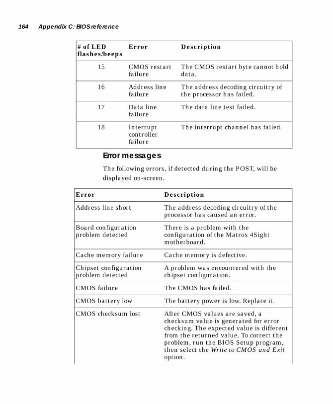
164 Appendix C: BIOS reference
Error messages
The following errors, if detected during the POST, will be displayed on-screen.
15 CMOS restart failure
The CMOS restart byte cannot hold data.
16 Address line failure
The address decoding circuitry of the processor has failed.
17 Data line failure
The data line test failed.
18 Interrupt controller failure
The interrupt channel has failed.
# of LED flashes/beeps
Error Description
Error Description
Address line short The address decoding circuitry of the processor has caused an error.
Board configuration problem detected
There is a problem with the configuration of the Matrox 4Sight motherboard.
Cache memory failure Cache memory is defective.
Chipset configuration problem detected
A problem was encountered with the chipset configuration.
CMOS failure The CMOS has failed.
CMOS battery low The battery power is low. Replace it.
CMOS checksum lost After CMOS values are saved, a checksum value is generated for error checking. The expected value is different from the returned value. To correct the problem, run the BIOS Setup program, then select the Write to CMOS and Exit option.
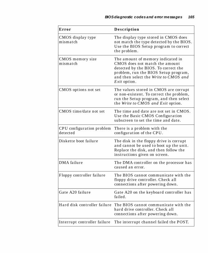
BIOS diagnostic codes and error messages 165
CMOS display type mismatch
The display type stored in CMOS does not match the type detected by the BIOS. Use the BIOS Setup program to correct the problem.
CMOS memory size mismatch
The amount of memory indicated in CMOS does not match the amount detected by the BIOS. To correct the problem, run the BIOS Setup program, and then select the Write to CMOS and Exit option.
CMOS options not set The values stored in CMOS are corrupt or non-existent. To correct the problem, run the Setup program, and then select the Write to CMOS and Exit option.
CMOS time/date not set The time and date are not set in CMOS. Use the Basic CMOS Configuration subscreen to set the time and date.
CPU configuration problem detected
There is a problem with the configuration of the CPU.
Diskette boot failure The disk in the floppy drive is corrupt and cannot be used to boot up the unit. Replace the disk, and then follow the instructions given on screen.
DMA failure The DMA controller on the processor has caused an error.
Floppy controller failure The BIOS cannot communicate with the floppy drive controller. Check all connections after powering down.
Gate A20 failure Gate A20 on the keyboard controller has failed.
Hard disk controller failure The BIOS cannot communicate with the hard drive controller. Check all connections after powering down.
Interrupt controller failure The interrupt channel failed the POST.
Error Description
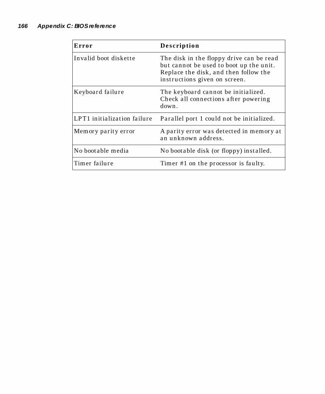
166 Appendix C: BIOS reference
Invalid boot diskette The disk in the floppy drive can be read but cannot be used to boot up the unit. Replace the disk, and then follow the instructions given on screen.
Keyboard failure The keyboard cannot be initialized. Check all connections after powering down.
LPT1 initialization failure Parallel port 1 could not be initialized.
Memory parity error A parity error was detected in memory at an unknown address.
No bootable media No bootable disk (or floppy) installed.
Timer failure Timer #1 on the processor is faulty.
Error Description

Appendix D: Technical reference
This appendix provides pin-out descriptions for connectors on the Matrox 4Sight motherboard, summarizes the key features of Matrox 4Sight and the Matrox Meteor-II family
of PC/104-Plus™ boards, and provides a detailed list of components included in Windows NT Embedded.

168 Appendix D: Technical reference
Matrox 4Sight technical reference
Motherboard■ EBX form factor (8” x 5¾” or 20.32cm x 14.61cm).
■ National Semiconductor® Geode™ GXLV processor running at 266 MHz.
■ Up to 128 Mbytes of SDRAM via 168-pin DIMM slot.
■ Can output to a VGA monitor, TV, VCR, or flat panel1.
■ Support for non-destructive overlay and 16-bit stereo audio I/O.
■ DiskOnChip® (optional) and 256 Kbyte flash BIOS.
■ 10/100 Mbit/sec Ethernet port.
■ Three 400 Mbit/sec IEEE 1394 ports.
■ Two RS-232 serial ports, parallel port, keyboard port, mouse
port, and floppy drive interface1.
■ 20 LVTTL or TTL compatible I/Os with interrupt-generation.
■ Supports up to three PC/104-Plus™ boards.
Chassis2
■ Integrated fan rated at 9-12 cfm (0.25-0.34 m3/min).
Optional hard drive2
■ 2.5” diameter, mounted inside chassis, UltraDMA support.
■ Resistant to shocks.
Power supply2 ■ Input: 100 ~ 240 Vac; output: 12 Vdc, 2.5 A (30 W).
■ External to chassis.
1. Accessible via motherboard only.2. Available with the Matrox 4Sight integrated unit.

Matrox 4Sight technical reference 169
LEDs■ Power: Power on/off.
■ Diagnostic: Communicates system errors.
■ 100 MBPS: On in 100BaseT mode; off in 10BaseT mode.
■ Activity: Blinks when transmitting/receiving packets.
Environmental specifications Matrox 4Sight motherboard
■ Ambient operating temperature with 200 lfm of air flow: 10 to 60° C.
■ Ambient operating temperature with no air flow: 10 to 40° C.
■ Storage temperature: -40 to 65° C.
■ Operating altitude: -300 to 3000 meters.
■ Storage altitude: -300 to 12000 meters.
■ Operating humidity: 10 to 90 % (non-condensing).
■ Storage humidity: 5 to 95 % (non-condensing).
■ Vibration, operating: 0.67 gRMS (5 - 500 Hz).
■ Vibration, storage: 36 RMS (5 - 500 Hz).
Matrox 4Sight integrated unit
■ Ambient operating temperature: 10 to 50° C.
■ Storage temperature: -40 to 65° C.
■ Operating altitude: -300 to 3000 meters.
■ Storage altitude: -300 to 12000 meters.
■ Operating humidity: 10 to 90 % (non-condensing).
■ Storage humidity: 5 to 95 % (non-condensing).
■ Vibration, operating: 0.67 gRMS (5 - 500 Hz).
■ Vibration, storage: 36 RMS (5 - 500 Hz).
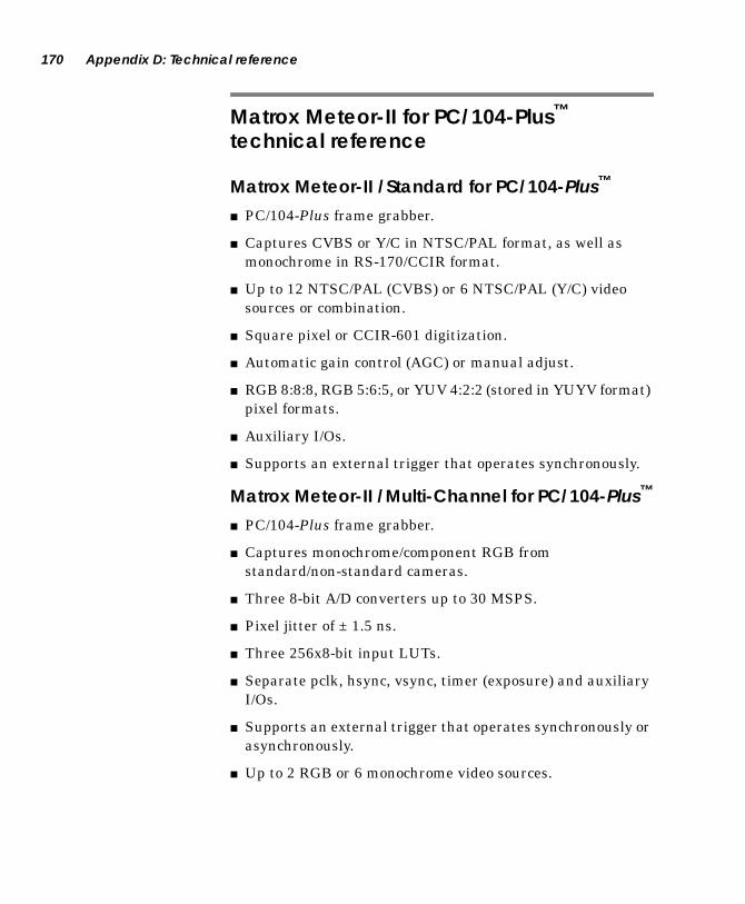
170 Appendix D: Technical reference
Matrox Meteor-II for PC/104-Plus™
technical reference
Matrox Meteor-II /Standard for PC/104-Plus™
■ PC/104-Plus frame grabber.
■ Captures CVBS or Y/C in NTSC/PAL format, as well as monochrome in RS-170/CCIR format.
■ Up to 12 NTSC/PAL (CVBS) or 6 NTSC/PAL (Y/C) video sources or combination.
■ Square pixel or CCIR-601 digitization.
■ Automatic gain control (AGC) or manual adjust.
■ RGB 8:8:8, RGB 5:6:5, or YUV 4:2:2 (stored in YUYV format) pixel formats.
■ Auxiliary I/Os.
■ Supports an external trigger that operates synchronously.
Matrox Meteor-II /Multi-Channel for PC/104-Plus™
■ PC/104-Plus frame grabber.
■ Captures monochrome/component RGB from standard/non-standard cameras.
■ Three 8-bit A/D converters up to 30 MSPS.
■ Pixel jitter of ± 1.5 ns.
■ Three 256x8-bit input LUTs.
■ Separate pclk, hsync, vsync, timer (exposure) and auxiliary I/Os.
■ Supports an external trigger that operates synchronously or asynchronously.
■ Up to 2 RGB or 6 monochrome video sources.

Pin-outs of front panel connectors 171
Matrox Meteor-II MJPEG module■ Available as an add-on to Matrox Meteor-II /Standard or
Matrox Meteor-II /Multi-Channel for PC/104-Plus™.
■ Performs lossy MJPEG/JPEG compression on monochrome or color video, lossless MJPEG/JPEG compression on monochrome video.
■ Maximum conversion rate of 30 Mpixels/sec.
■ 64 Kbyte SRAM.
Pin-outs of front panel connectors
Ethernet connectorThe ethernet connector is an 8-pin, RJ45 male connector.
Pin Signal I/O Description1 TD+ O Transmit Data+2 TD- O Transmit Data-3 RD+ I Receive Data+4 NC - Not connected5 NC - Not connected6 RD- I Receive Data-7 NC - Not connected8 NC - Not connected

172 Appendix D: Technical reference
TV output connectorThe TV output connector is a 9-pin, DB female connector.
The DB9M-TO-4BNC cable can be purchased from Matrox or from Virgo Trading Co. Ltd.
Pin Signal I/O Description1 NC - Not connected2 GND - Ground3 CSYNC O TTL Composite Sync4 GND - Ground5 BLUE_COMP O Encoded Video Output: Blue or
CVBS6 GND - Ground7 GREEN_C O Encoded Video Output: Green or C8 GND - Ground9 RED_Y O Encoded Video Output: Red or Y
15
9 6
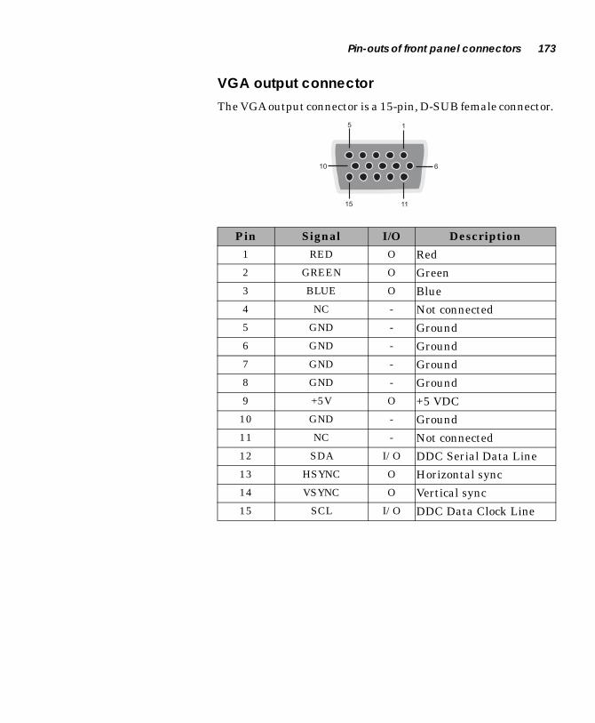
Pin-outs of front panel connectors 173
VGA output connectorThe VGA output connector is a 15-pin, D-SUB female connector.
Pin Signal I/O Description1 RED O Red2 GREEN O Green3 BLUE O Blue4 NC - Not connected5 GND - Ground6 GND - Ground7 GND - Ground8 GND - Ground9 +5V O +5 VDC10 GND - Ground11 NC - Not connected12 SDA I/O DDC Serial Data Line13 HSYNC O Horizontal sync14 VSYNC O Vertical sync15 SCL I/O DDC Data Clock Line
15
15 11
10 6

174 Appendix D: Technical reference
Video input connectorThe video input connector is a 44-pin, DB-HD female
connector1*. The pin-out of this connector depends on whether the Matrox 4Sight motherboard hosts a Matrox Meteor-II /Standard or Matrox Meteor-II /Multi-Channel frame
grabber for PC/104-Plus™.
1. Note that the DC_OUT signal is protected with a 0.5A auto-resettable fuse.
Matrox Meteor-II /Standard
Pin Signal I/O Description1 DC_OUT O +12V Power Supply2 VID_IN12 I Video Input 12 3 GND - Ground4 GND - Ground5 GND - Ground6 NC - Not connected7 NC - Not connected8 USER2_OUT O User Output9 USER2_IN I User Input10 NC - Not connected11 VID_IN5 I Video Input 5 12 NC - Not connected13 VID_IN3 I Video Input 3 14 GND - Ground15 VID_IN1 I Video Input 1 16 DC_OUT O +12V Power Supply
15 1*
30 16
44 31
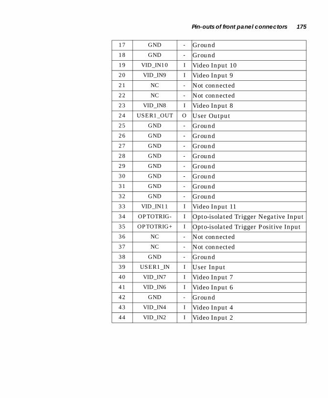
Pin-outs of front panel connectors 175
17 GND - Ground18 GND - Ground19 VID_IN10 I Video Input 1020 VID_IN9 I Video Input 9 21 NC - Not connected22 NC - Not connected23 VID_IN8 I Video Input 8 24 USER1_OUT O User Output25 GND - Ground26 GND - Ground27 GND - Ground28 GND - Ground29 GND - Ground30 GND - Ground31 GND - Ground32 GND - Ground33 VID_IN11 I Video Input 11 34 OPTOTRIG- I Opto-isolated Trigger Negative Input35 OPTOTRIG+ I Opto-isolated Trigger Positive Input36 NC - Not connected37 NC - Not connected38 GND - Ground39 USER1_IN I User Input40 VID_IN7 I Video Input 7 41 VID_IN6 I Video Input 6 42 GND - Ground43 VID_IN4 I Video Input 4 44 VID_IN2 I Video Input 2

176 Appendix D: Technical reference
Matrox Meteor-II /Multi-Channel
Pin Signal I/O Description1 DC_OUT O +12V Power Supply2 HSYNC I/O TTL Horizontal Sync3 GND - Ground4 GND - Ground5 GND - Ground6 NC - Not connected7 NC - Not connected8 USER2_OUT O TTL User Output9 USER2_IN I TTL User Input
10 NC - Not connected11 VID2_IN1 I Video Input 2 (Red) 12 NC - Not connected13 VID1_IN3 I Video Input 1 (Blue) 14 GND - Ground15 VID1_IN1 I Video Input 1 (Red)16 DC_OUT O +12V Power Supply17 GND - Ground18 GND - Ground19 CLK_IN I TTL Clock Input20 TRIG I TTL Trigger Input21 NC - Not connected22 NC - Not connected23 EXP(2) O TTL Exposure2 Output24 USER1_OUT O TTL User Output25 GND - Ground26 GND - Ground27 GND - Ground28 GND - Ground29 GND - Ground30 GND - Ground31 GND - Ground

Pin-outs of front panel connectors 177
Auxiliary I/O connector
The auxiliary I/O connector is a 25-pin, D-SUB male connector.
32 VSYNC I/O TTL Vertical Sync33 CLK_OUT O TTL Clock Output34 OPTOTRIG- I Opto-isolated Trigger Negative Input35 OPTOTRIG+ I Opto-isolated Trigger Positive Input36 NC - Not connected37 NC - Not connected38 EXP(1) O TTL Exposure1 Output39 USER1_IN I TTL User Input40 VID2_IN3 I Video Input 2 (Blue) 41 VID2_IN2 I Video Input 2 (Green) 42 GND - Ground43 SYNC_IN I Video Input Sync44 VID1_IN2 I Video Input 1 (Green)
Pin Signal1 GND2 LVTTL I/O 03 LVTTL I/O 24 LVTTL I/O 45 LVTTL I/O 66 LVTTL I/O 87 GND8 LVTTL I/O 109 LVTTL I/O 1210 LVTTL I/O 1411 LVTTL I/O 1612 LVTTL I/O 18
131
2514

178 Appendix D: Technical reference
Pin-outs of back panel connectors
Parallel port connectorThe parallel port connector is a 25-pin, D-SUB female connector.
13 GND14 GND15 LVTTL I/O 116 LVTTL I/O 317 LVTTL I/O 518 LVTTL I/O 719 LVTTL I/O 920 GND21 LVTTL I/O 1122 LVTTL I/O 1323 LVTTL I/O 1524 LVTTL I/O 1725 LVTTL I/O 19
Pin Signal I/O Description1 /STROBE O Strobe2 D0 O Data Bit 03 D1 O Data Bit 14 D2 O Data Bit 25 D3 O Data Bit 36 D4 O Data Bit 47 D5 O Data Bit 58 D6 O Data Bit 69 D7 O Data Bit 7

Pin-outs of back panel connectors 179
IEEE 1394 connectorsThe three IEEE 1394 port connectors are identical and provide connection to either 6-wire or 4-wire IEEE 1394 cables.
10 /ACK I Acknowledge11 BUSY I Busy12 PE I Paper End13 SEL I Select14 /AUTOFD O Autofeed15 /ERROR I Error16 /INIT O Initialize17 /SELIN O Select In18 GND - Ground19 GND - Ground20 GND - Ground21 GND - Ground22 GND - Ground23 GND - Ground24 GND - Ground25 GND - Ground
Pin Signal1 +12V, 0.25A2 GND3 /TPB4 TPB5 /TPA6 TPA

180 Appendix D: Technical reference
Serial port connectorThe two serial port connectors are identical and are 9-pin, D-SUB male connectors.
Mouse and keyboard connectors
The mouse and keyboard connectors are 6-pin, PS/2-style female connectors.
Pin Signal I/O Description1 CD I Carrier Detect2 RXD I Receive Data3 TXD O Transmit Data4 DTR O Data Terminal Ready5 GND - Ground6 DSR I Data Set Ready7 RTS O Request to Send8 CTS I Clear to Send9 RI I Ring Indicator
Pin Signal I/O Description1 DATA I/O Key Data2 NC - Not connected3 GND - Ground4 VCC O Power, +5 VDC5 CLK O Clock6 NC - Not connected
1 5
6 9

Pin-outs of internal connectors 181
Pin-outs of internal connectors
Floppy disk connector
The floppy disk connector is a 34-pin, IDC male connector.
Pin Signal I/O Description1 GND - Ground2 /REDWC O Density Select3 GND - Ground4 NC - Reserved5 GND - Ground6 DRATE O Data Rate7 GND - Ground8 /INDEX I Index9 GND - Ground10 /MOTEA O Motor Enable A11 GND - Ground12 /DRVSB O Drive Sel B13 GND - Ground14 /DRVSA O Drive Sel A15 GND - Ground16 /MOTEB O Motor Enable B17 GND - Ground18 /DIR O Direction19 GND - Ground20 /STEP O Step21 GND - Ground22 /WDATA O Write Data23 GND - Ground24 /WGATE O Floppy Write Enable25 GND - Ground26 /TRK00 I Track 027 GND - Ground28 /WPT I Write Protect

182 Appendix D: Technical reference
IDE interface connectorThe IDE interface connector is a 40-pin, IDC male connector.
29 MEDSB I Media Sense B30 /RDATA I Read Data31 GND - Ground32 /SIDE1 O Head Select33 MEDSA I Media Sense A34 /DSKCHG O Disk Change
Pin Signal I/O Description1 /RESET O Reset2 GND - Ground3 DD7 I/O Data 74 DD8 I/O Data 85 DD6 I/O Data 66 DD9 I/O Data 97 DD5 I/O Data 58 DD10 I/O Data 109 DD4 I/O Data 410 DD11 I/O Data 1111 DD3 I/O Data 312 DD12 I/O Data 1213 DD2 I/O Data 214 DD13 I/O Data 1315 DD1 I/O Data 116 DD14 I/O Data 1417 DD0 I/O Data 018 DD15 I/O Data 1519 GND - Ground20 KEY - Key21 DMARQ O DMA Request

Pin-outs of internal connectors 183
ATA (44) internal connectorThe ATA (44) internal connector is a 44-pin, IDC male connector.
22 GND - Ground23 /DIOW O Write Strobe24 GND - Ground25 /DIOR O Read Strobe26 GND - Ground27 IORDY I I/O Ready 28 GND - Ground29 /DMACK I DMA Acknowledge30 GND - Ground31 INTRQ I Interrupt Request32 /IOCS16 - IO ChipSelect 1633 DA1 O Address 134 NC - Not connected35 DA0 O Address 036 DA2 O Address 237 /IDE_CS0 O (1F0-1F7)38 /IDE_CS1 O (3F6-3F7)39 /ACTIVE O Led driver40 GND - Ground
Pin Signal I/O Description1 /RESET O Reset2 GND - Ground3 DD7 I/O Data 74 DD8 I/O Data 85 DD6 I/O Data 66 DD9 I/O Data 9

184 Appendix D: Technical reference
7 DD5 I/O Data 58 DD10 I/O Data 109 DD4 I/O Data 410 DD11 I/O Data 1111 DD3 I/O Data 312 DD12 I/O Data 1213 DD2 I/O Data 214 DD13 I/O Data 1315 DD1 I/O Data 116 DD14 I/O Data 1417 DD0 I/O Data 018 DD15 I/O Data 1519 GND - Ground20 KEY - Key21 DMARQ O DMA Request22 GND - Ground23 /DIOW O Write Strobe24 GND - Ground25 /DIOR O Read Strobe26 GND - Ground27 IORDY I I/O Ready28 GND - Ground29 /DMACK I DMA Acknowledge30 GND - Ground31 INTRQ I Interrupt Request32 /IOCS 16 - IO ChipSelect 1633 DA1 O Address 134 NC - Not connected35 DA0 O Address 036 DA2 O Address 237 /IDE_CS0 O (1F0-1F7)38 /IDE_CS1 O (3F6-3F7)39 /ACTIVE O Led driver

Pin-outs of internal connectors 185
Flat panel interface connector
The flat panel interface connector is a 41-pin, dual-header
connector1*.
40 GND - Ground41 +5VL O +5 VDC (Logic)42 +5VM O +5 VDC (Motor)43 GND - Ground44 /TYPE O Type (0=ATA)
Pin Signal I/O Description1 GND - Ground2 FP_CLK O Dot clock3 GND - Ground4 FP_HSYNC O Horizontal sync5 FP_VSYNC O Vertical sync6 GND - Ground7 GND - Ground8 GND - Ground9 R0 O Red data (LSB)10 R1 O Red data11 R2 O Red data12 GND - Ground13 R3 O Red data14 R4 O Red data15 R5 O Red data (MSB)16 GND - Ground17 GND - Ground18 GND - Ground19 G0 O Green data (LSB)20 G1 O Green data21 G2 O Green data
1. Note that the VCC_LCD signal is protected with a 0.5A auto-resettable fuse.
13
41
24
40.
.
.
.
.
.
.
.
.
.
.
.
.
.
.
.
.
.
.
.
.
.
.
.
.
.
.
.
Front panel
*

186 Appendix D: Technical reference
Flat panel backlight connector
The flat panel backlight connector is a 5-pin, locking
connector1*.
22 GND - Ground23 G3 O Green data24 G4 O Green data25 G5 O Green data (MSB)26 GND - Ground27 GND - Ground28 GND - Ground29 B0 O Blue data (LSB)30 B1 O Blue data31 B2 O Blue data32 GND - Ground33 B3 O Blue data34 B4 O Blue data35 B5 O Blue data36 GND - Ground37 FP_DISP_ENA O Data enable (high)38 MVA O Best viewing (high)39 VCC_LCD O Power supply, 3.3 V40 VCC_LCD O Power supply, 3.3 V41 DPS O Scan direction select (open)
Pin Signal I/O Description1 VDD O Power supply, 12 V
2 VDD O Power supply, 12 V
3 GND - Ground4 GND - Ground5 BRTHL - Luminance select (open)
1. Note that the VDD signal is protected with a 0.5A auto-resettable fuse.
1
5
Front panel
*
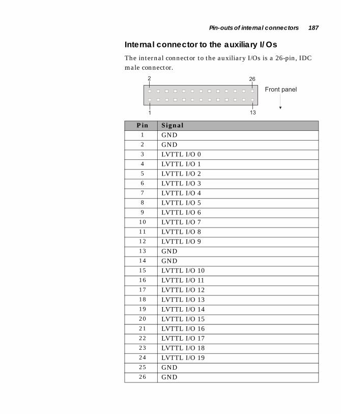
Pin-outs of internal connectors 187
Internal connector to the auxiliary I/Os
The internal connector to the auxiliary I/Os is a 26-pin, IDC male connector.
Pin Signal1 GND2 GND3 LVTTL I/O 04 LVTTL I/O 15 LVTTL I/O 26 LVTTL I/O 37 LVTTL I/O 48 LVTTL I/O 59 LVTTL I/O 610 LVTTL I/O 711 LVTTL I/O 812 LVTTL I/O 913 GND14 GND15 LVTTL I/O 1016 LVTTL I/O 1117 LVTTL I/O 1218 LVTTL I/O 1319 LVTTL I/O 1420 LVTTL I/O 1521 LVTTL I/O 1622 LVTTL I/O 1723 LVTTL I/O 1824 LVTTL I/O 1925 GND26 GND

188 Appendix D: Technical reference
Unit Reliability Prediction Mean time between failure (MTBF)
Unit Name Description Repair Category Steady State
Failure Rate FITs
MTBF in Hours
Factory Repair
Field Repairable
Other
Board Modules
Meteor II/MC PC104 (Module)
X 1741.88 574092.4
861-0100 (Motherboard)
X 4789.26 208800.5
64 MB DIMM Memory (Module)
X 273.80 3652300.9
*DiskOnChip Memory (Module)
X 685.50 1458789.2
2.5 in. Hard Drive (Life)
X 50000.00 20000.0
Miscellaneous Fan X 20000.0 50000.0
Power Supply (30 Watts)
X 20000.0 50000.0
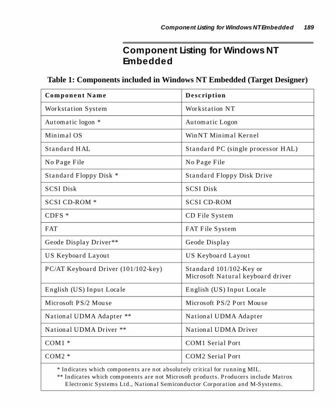
Component Listing for Windows NT Embedded 189
Component Listing for Windows NT Embedded
Table 1: Components included in Windows NT Embedded (Target Designer)
Component Name Description
Workstation System Workstation NT
Automatic logon * Automatic Logon
Minimal OS WinNT Minimal Kernel
Standard HAL Standard PC (single processor HAL)
No Page File No Page File
Standard Floppy Disk * Standard Floppy Disk Drive
SCSI Disk SCSI Disk
SCSI CD-ROM * SCSI CD-ROM
CDFS * CD File System
FAT FAT File System
Geode Display Driver** Geode Display
US Keyboard Layout US Keyboard Layout
PC/AT Keyboard Driver (101/102-key) Standard 101/102-Key or Microsoft Natural keyboard driver
English (US) Input Locale English (US) Input Locale
Microsoft PS/2 Mouse Microsoft PS/2 Port Mouse
National UDMA Adapter ** National UDMA Adapter
National UDMA Driver ** National UDMA Driver
COM1 * COM1 Serial Port
COM2 * COM2 Serial Port
* Indicates which components are not absolutely critical for running MIL.** Indicates which components are not Microsoft products. Producers include Matrox
Electronic Systems Ltd., National Semiconductor Corporation and M-Systems.

190 Appendix D: Technical reference
LPT1 * LPT1 Port
Geode Audio *, ** Geode Audio Driver
Domain Participation * Workgroup Participation
Matrox 10/100 Fast Ethernet Controller ** Matrox PCI 10/100 Fast Ethernet Controller
Matrox 10/100 Fast Ethernet Driver ** Matrox PCI 10/100 Fast Ethernet Driver
TCP/IP TCP/IP Protocol
Computer Browser Computer Browser Service
DCHP Client Domain Host Configuration Protocol Client Service
LAN Manager Server LAN Manager Server Service
LAN Manager Workstation LAN Manager Workstation Service
Messenger Messenger Service
NetBIOS NetBIOS Interface Service
NT LM Security Support Provider NT Lan Manager Service
RPC Remote Procedures Call Service
Simple TCP Services Simple TCP Services
WinSock Windows Sockets Service
Net Command (NET.EXE) * Network Command-Line Configuration Utility (net.exe)
TCP/IP Utilities TCP/IP Utilities
OLE/COM OLE and COM
Registry Editor * Registry Editor (regedt32) Utility
Table 1: Components included in Windows NT Embedded (Target Designer)
Component Name Description
* Indicates which components are not absolutely critical for running MIL.** Indicates which components are not Microsoft products. Producers include Matrox
Electronic Systems Ltd., National Semiconductor Corporation and M-Systems.

Component Listing for Windows NT Embedded 191
User Manager for Domains * User Manager for Domains
Event Viewer * Event Viewer Utility
Task Manager * Task Manager Utility
Event Logging * Event Logging Service
MS Sans Serif Font MS Sans Serif Font
Display Common Common Display Component
Keyboard Drivers Common Keyboard Drivers Common Support
Keyboard Locale Common Keyboard Locale Common Support
Mouse Common Mouse Common Support
Network Common Network Common KIT
Parallel Ports Common * Parallel Ports Common
Printer Common * Printer Common Component
SCSI Common * SCSI Driver Common Support
Serial Ports Common * Serial Ports Common Support
Virtual Memory Common Virtual Memory Common Component
Command Shell Command Window Shell
Add Printer Wizard * Add Printer Wizard
Explorer * Desktop Explorer
File Attribute Command (ATTRIB.EXE) * File Attribute Configuration Command Utility
Windows NT Command Prompt Windows NT Command Prompt
Notepad * Notepad Accessory
Table 1: Components included in Windows NT Embedded (Target Designer)
Component Name Description
* Indicates which components are not absolutely critical for running MIL.** Indicates which components are not Microsoft products. Producers include Matrox
Electronic Systems Ltd., National Semiconductor Corporation and M-Systems.

192 Appendix D: Technical reference
DirectDraw DirectDraw
ActiveMIL ** ActiveMIL - Matrox Imaging Library
Miscellaneous Files Support ** Miscellaneous Files Support
MIL ** MIL - Matrox Imaging Library
DiskOnChip 2000 Driver Support ** DiskOnChip 2000 Driver Support
Rainbow Sentinel Driver ** Rainbow Sentinel Driver
AVI ** AVI
NTConfig Support ** NTConfig Support
Table 1: Components included in Windows NT Embedded (Target Designer)
Component Name Description
* Indicates which components are not absolutely critical for running MIL.** Indicates which components are not Microsoft products. Producers include Matrox
Electronic Systems Ltd., National Semiconductor Corporation and M-Systems.

Appendix E: Glossary
This appendix defines some of the specialized terms used in this Matrox 4Sight document.

194 Appendix E: Glossary
■ ASIC
Application-specific integrated circuit. An integrated circuit custom-made to meet the requirements of a specific application. It integrates several digital and/or analog functions into a single die. This results in a reduction in cost, board area, and power consumption, while improving performance when compared to an equivalent implementation using off-the-shelf components.
■ Band
One of the surfaces of a buffer. A grayscale image requires one band. A color image requires three bands, one for each color component.
■ Bandwidth
A term describing the capacity to transfer data. Greater bandwidth is needed to sustain a higher transfer rate. Greater bandwidth can be achieved, for example, by using a wider bus.
■ Bus
A pathway along which signals are sent, generally in two directions, for communication of data.
■ Color component
One of the components that make up a color space. Typically, each component of a color image is stored in a separate band of a multi-band buffer.
■ Color space
A color space is a way of representing and describing the complete range of perceived colors. A number of color spaces have been developed. Common color spaces are RGB and HSL. Both describe the same range of perceivable colors.
■ Composite sync
A synchronization signal made up of two components: one horizontal and one vertical.

195
■ Contiguous memory
A block of physical memory occupying a single, consecutive series of locations.
■ DCF
Digitizer Configuration Format. A DCF defines the input data format and among other things, how to accept or generate video timing signals such as horizontal sync, vertical sync, and pixel clock.
■ DHCP
Dynamic Host Configuration Protocol. A server that eliminates the need to assign and manage unique IP addresses for all of the machines on a network.
■ Display memory
See frame buffer.
■ Driver
A software program that services an operating system so that the operating system can use a hardware device.
■ Ethernet
A standard for the physical wiring and signalling on a LAN.
See also Local Area Network.
■ Ethernet cable
A wire similar to a telephone cable that carries the signals between Ethernet devices.
■ Exposure time
Refers to the period during which the image sensor of a camera is exposed to light. As the length of this period increases, so does the image brightness.
■ Field
One of the two halves that make up an image. One half consists of the image’s odd lines (known as the odd field); the other half consists of the image’s even lines (known as the even field).

196 Appendix E: Glossary
■ Frame
A single image grabbed from a video camera.
■ Frame buffer
A frame buffer is a dedicated storage area used for display. Since a computer sends out data faster than a screen can display it, the data is temporarily stored in the frame buffer. Matrox imaging boards that have a display section typically have two frame buffer surfaces: a dedicated or dynamically allocated main (underlay) surface and an overlay (VGA) surface. Separate VGA boards typically have only one frame buffer surface, a VGA frame buffer surface.
If keying is enabled, those areas of the overlay frame buffer surface that have a specified color allow the underlay frame buffer surface to show through.
■ Full duplex mode
A network device that can send and receive information simultaneously. For example, a switch can operate in full duplex mode.
■ Grab
To acquire an image from a camera.
■ Half duplex mode
A network device that can only send or receive data, but not do both simultaneously. For example, all hubs operate in half duplex mode.
■ Horizontal sync
The part of a video signal that indicates the end of a line and the start of a new one.
See also vertical sync.
■ HSL
A color space that represents color using components of hue, saturation, and luminance. The hue component describes the actual color of a pixel. The saturation component describes the concentration of that color. The luminance component describes the combined brightness of the primary colors.

197
■ Host
In general, Host refers to the principal CPU in one’s computer. It can also refer to the principal computer in a multi-computer set-up.
■ Interlaced scanning
Describes a transfer of data in which the odd-numbered lines of the source are written to the destination buffer first and then the even-numbered lines (or vice-versa).
See also progressive scanning.
■ Internet Protocol (IP) address
The electronic address of a computer (station) on a TCP/IP network, which is unique for every client and server station. Client workstations have either a permanent or dynamically assigned address. The IP address is a dot address that is written as four sets of numbers separated by periods, also called dotted quad notation (for example, 203.142.62.2). The TCP/IP packet uses 32 bits to hold the IP address.
■ Keying
A display effect that switches between two display sources depending on the pixel values in one of the sources. Keying is used to make portions of the overlay frame buffer surface transparent so that corresponding areas of the underlay frame buffer surface can show through it.
■ Latency
The time from when an operation is started to when the final result is produced.
■ Live processing
See real-time processing.
198 Appendix E: Glossary
■ Local Area Network (LAN)
A group (or network) of computers and other devices that are connected together to share the resources (files, printers, devices, and other services (such as Internet access)) of a single workstation or server within a small geographical area. The main LAN connection technology used is Ethernet cable, which connects users (clients) to the LAN’s server. Clients download applications and/or services from the server, and then run or use them from their local computer.
■ LUT mapping
Look-up table mapping. A point-to-point operation that uses a table to define a replacement value for each possible pixel value in an image.
■ MSPS
Mega samples per second.
■ PCI
Peripheral Component Interconnect. An expansion bus standard for the ’90s.
■ PLC
Programmable Logic Controller. A device used to automate monitoring and control of industrial plants. It can be used as a stand-alone device or in conjunction with data acquisition.
■ PLL
Phase-locked loop. A technique in electronic circuitry for maintaining synchronization. The circuit receives its timing from input signals, but also provides a feedback circuit for synchronization. The resulting output signal varies according to differences between the reference signal and the feedback signal. In particular, a frame grabber’s PLL creates a pixel clock, which is a multiple of a referenced signal’s frequency. In this context, the referenced signal is usually the horizontal sync. A PLL adjusts the pixel clock frequency according to changes or variations in its reference signal. Adjusting the pixel clock frequency ensures that the same number of pixels appears on every line.
199
■ Progressive scanning
Describes a transfer of data in which the lines of the source input device are written sequentially into the destination buffer.
Also known as non-interlaced. See also interlaced scanning.
■ Protocol
A set of standards (rules/formats) for transmitting information "packets" between computer software and hardware devices. Information packets are structured according to the standards of a protocol. On a network, the data link or Media Access Control protocol standard, such as the CSMA/CD, provides the access method, and TCP/IP provides the control and routing method to transmit (move) information packets.
■ PSG
Programmable synchronization generator. It has various functions related to video synchronization and control. For example, it supplies feedback signals to the PLL, and is fully responsible for the sampling clock value.
■ RAMDAC
Random access memory digital-to-analog converter. A digital to analog converter that includes static RAM for use as a look-up table.
■ Real-time processing
The processing of an image as quickly as the next image is grabbed.
Also known as live processing.
■ Reference levels
The zero and full-scale levels of an analog-to-digital converter. Voltages below a black reference level are converted to the minimum pixel value; voltages above a white reference level are converted to the maximum pixel value. Together with the analog gain factor, the reference levels affect the brightness and contrast of the resulting image.

200 Appendix E: Glossary
■ RGB
A color space that represents color using the primary colors (red, green and blue) as components.
■ Subnet Mask
The sequence of numbers that the router uses to determine which parts of the 32-bit IP address is specific to the subnetwork (that is, common to all of the machines on the network) and should be used for transmitting the information "packet" to the subnetwork. This mask saves the router from having to handle the entire 32-bit IP address; instead, it can look at only the bits enabled (set to "1") by the mask. For example, if the network and subnet addresses are contained in the upper 24 bits, and the specific host address is contained in the lower 8 bits, then you can convey this information to the router to allow quicker transmission to the subnet by passing the following mask value: 255.255.255.0 (11111111.11111111.11111111.00000000).
■ TCP/IP (Transmission Control Protocol/ Internet Protocol)
The basic communication protocol (or language) of the Internet that has become the global standard for network communications since it ensures faithful data transmission. TCP/IP uses the client-server communication model, in which a computer user (client) makes requests and is provided services by a network computer (server). TCP/IP is a two-layered protocol. TCP is the upper transport layer, which ensures delivery of the entire file/message. TCP manages the assembly of files/messages into "packets" that are transmitted to and received by another TCP layer. That TCP layer then reassembles the packets into its original format. IP is the lower network layer, which routes the data to different destinations (LANs or WANs) based on the network address. TCP/IP is a routable protocol, which ensures that all messages contain the address of both the destination computer (station) and destination network. This makes it possible for messages to be transmitted to multiple networks.
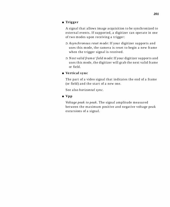
201
■ Trigger
A signal that allows image acquisition to be synchronized to external events. If supported, a digitizer can operate in one of two modes upon receiving a trigger:
❐ Asynchronous reset mode: If your digitizer supports and uses this mode, the camera is reset to begin a new frame when the trigger signal is received.
❐ Next valid frame/field mode: If your digitizer supports and uses this mode, the digitizer will grab the next valid frame or field.
■ Vertical sync
The part of a video signal that indicates the end of a frame (or field) and the start of a new one.
See also horizontal sync.
■ Vpp
Voltage peak to peak. The signal amplitude measured between the maximum positive and negative voltage peak excursions of a signal.

202 Appendix E: Glossary

Index
Aacquisition features
/Multi-Channel 116/Standard 112
ActiveMIL/ActiveMIL-Lite 19Activity LED 106, 169Advanced Configuration subscreen 156advanced wear levelling 104altitude limitations 169ATA (44) internal connector 15
pin-out 183audio input/output 39, 107, 162auto-logon
bypassing 46changing settings 139
automatic gain control/Multi-Channel 117/Standard 115
auto-popupchanging 141
auxiliary I/Omapping to interrupt line 143
auxiliary I/Os 38, 107connector pin-out 177internal connector pin-out 187
BBasic CMOS Configuration subscreen 151beep codes 162BIOS 105
beep codes 162boot method 155boot order 154changing configurations 150CMOS memory 150
extended memory available 151device list 155diagnostic codes 162drive assignment 153error messages 162, 164fast boot 155fields 151, 154hard drive selection 152
keyboard optionschanging 151
memory speed setting 156parallel port address 157parallel port mode 156selecting auxiliary I/O IRQs 157Setup program 150upgrading 148video memory 154wake option 156
block diagramsMatrox 4Sight motherboard 102
BNC-TO-SVHS cable 23boot fields, BIOS 152Boot Method field, BIOS 155boot sequence 154
Ccables
BNC-TO-SVHS 23DB9M-TO-4BNC 23, 39DBHD44-TO-13BNC 23DBHD44-TO-8BNC 23UTP5/UTP3 31
CD-ROM driveconnecting to 77
chassis 108removing 75
chassis (custom) 96CMOS memory 105, 150component listing 189computer name
changing 137connecting to
CD-ROM drive 77flat panel 87floppy drive 76hard drive 77IDE device 77IEEE 1394 ports 37keyboard 29LAN 31mouse 29parallel interface 38printing devices 35serial interface 38stereo audio device 39, 107, 162

TV monitor 39VCR 39VGA monitor 30video input devices 35
connectors, location on motherboard 16contents, Matrox 4Sight package 22custom
chassis 96fan 97power supply 97
custom modules 96
DDB9M-TO-4BNC cable 23, 39DBHD44-TO-13BNC cable 23DBHD44-TO-8BNC cable 23DBHD44-TO-8BNC/O
cable 23development environments 54Diagnostic LED 169DIMM slot 89, 102DiskOnChip® 15, 104
write capacity 105display capabilities 103DMA memory
changing settings 90MILConfig utility 92Mildrv utility 90
domainjoining 142
drive fields, BIOS 153driver
display 78Ethernet 80IDE Ultra DMA 79installing devices 78Intel Ethernet 81Matrox Ethernet 81
EEBX form factor 14, 102ECP mode 107embedded operating system 18encoder, NTSC/PAL/RGB 14, 103enhanced parallel port mode 107environmental specifications 169
EPP mode 107error messages 162, 164Ethernet
100BaseT operation 31, 10610BaseT operation 31, 106changing connection type 136communication modes 34connecting to a LAN 31installing driver 80
Intel 81Matrox 81
Ethernet interface 15, 31, 106connector pin-out 171
exampleMfocus.exe 55
extended capabilities port mode 107external connections 28external memory 102
FF1 Error Wait field, BIOS 152fan (custom) 97fatal errors 162fields, BIOS 151, 154flash memory 15, 105flat panel
backlight connector pin-out 186connecting to 87interface connector pin-out 185
Floppy A field, BIOS 153floppy drive
connecting to 76connector pin-out 181supported capacities 107
Ggrab section
gain control/Multi-Channel 117/Standard 115
lookup table/Multi-Channel 121
low-pass filter/Multi-Channel 117/Standard 114
performance

/Multi-Channel 117/Standard 114
trigger/Multi-channel 120/Standard 115
video decoder/Standard 114
graphics overlay 15
Hhandling precautions 23hard drive
connecting to 77hard drive, integrated unit 104humidity specifications 169
II/O capabilities 106IDE device, connecting to 77IDE driver
choosing 143IDE fields, BIOS 152IDE interface 15
connector pin-out 182IEEE 1394 ports
connector pin-out 179Digital Camera Specification (DCS) 15, 37,105
further reading 106installing
PC/104-Plus board 87Windows NT 78
Installing device drivers 78integrated unit 14, 104Intel Ethernet driver 81Intellicam 19IP address
changing 134
Jjoining a domain 142
Kkeyboard connection 29, 180keyboard layout
changing 141
LLAN, connecting to 31LEDs
100Mbps LED 106, 169low-pass filter
/Multi-Channel 117/Standardl 114
LVTTL I/Os 38, 107
Mmaster mode 119Matrox 4Sight
BIOS 150block diagram 102chassis 108contents of package 22display capabilities 103external connections 28handling precautions 23I/O capabilities 106integrated unit 14location of components and connectors 16motherboard 14networking capabilities 15, 106overview of features 14, 168power supply 109processing capabilities 102storage capabilities 104video input devices 35
Matrox Ethernet driver 81Matrox Meteor-II frame grabber 35
removing components 63Matrox Meteor-II frame grabber family 112
interfacing 23overview 17, 170
Matrox MJPEG Module 122compression 124decompression 124FPGA 123
mean time between failure (MTBF) 188
memorydefault settings 90
Memory Speed Setting field, BIOS 157MIL/MIL-Lite 18MILConfig 92, 127–128MILDrv 90MJPEG decompression 124MJPEG module for PC/104-PlusTM
overview 171MMXTM technology 14, 103mode
master 119–120slave 119
monitor problems 126motherboard
block diagram 102environmental specifications 169features 14host modules 96location of components 16
mouse connection 29, 180
NNational Semiconductor® GeodeTM GXLV pro-cessor 14, 102–103, 156
companion chip 102network components 132networking capabilities 15, 106non-destructive graphics overlay 15non-fatal errors 162NTConfig 128, 130NTSC/PAL/RGB encoder 14, 103
Ooperating humidity 169operating system, embedded 18operating temperature 169optional items
frame grabberMatrox Meteor-IIMulti-Channel 22Standard 22
Matrox Inspector 22MIL 22MIL-Lite 22
overlay 15
Pparallel interface 38, 107
connector pin-out 177–178Parallel Port Address field, BIOS 157Parallel Port Mode field, BIOS 157PC/104-PlusTM board
Matrox Meteor-II frame grabber family 17PC/104-PlusTM board
installing 87PC/104-PlusTM interface 15, 108PCI shroud 88PCMEMORYSIZE 91POSTs 162Power LED 169power supply 109power supply (custom) 97processing capabilities 102
Rreception information 106refresh rate 14remote management tasks 18removing the chassis 75rotary switch, PC/104-PlusTM board 88RS-232 serial interface 38
SSDRAM module 14, 89serial interface 38, 106
connector pin-out 180shell command line
changing 140Show ‘Hit Del’ field, BIOS 152slave mode 119software
overview 18storage capabilities 104storage temperature 169synchronization 119syncserv command 62system owner
changing 140

Ttemperature, operating/storage 169timing
field rate/Standard 114
line rate/Standard 114
lines/frame/Multi-Channel 117/Standard 114
pixel rate/Standard 114
pixels/line/Multi-Channel 117/Standard 114
sampling rate/Multi-Channel 117/Standard 114
transmission information 106trigger
/Multi-Channel 120/Standard 115
troubleshooting 126TrueFFS technology 104TTL I/Os 38, 107TV monitor, connecting to 39TV output connector pin-out 172Typematic Delay field, BIOS 151Typematic Rate field, BIOS 151
UUltraDMA support 104upgrading
BIOS 148user accounts
bypassing the auto-logon feature 46changing settings 139
UTP5/UTP3 cable 31
VVCR, connecting to 39VGA display monitor 30VGA monitor, connecting to 30VGA output connector pin-out 173VIA features 121
vibration specifications 169video decoder 113video formats supported 114
/1394 105/Multi-Channel
monochrome 116RGB 116
/StandardNTSC 35PAL 35Y/C 35
video input connector pin-out 174
Wwarranty 12Windows CE 18, 155
boot options 159Windows NT Embedded 32, 42, 58
component listing 189registry
auto-logon 139auto-popup feature 141choosing an IDE driver 143computer name 137display components 138Ethernet connection type 136joining a domain 142keyboard layout 141machine name check feature 145mapping auxiliary I/Os 143network components 133shell command line 140system owner 140
using NTConfig 130write-capacity 105


Regulatory Compliance
FCC Compliance Statement
Warning
Changes or modifications to this unit not expressly approved by the party responsible for the compliance could void the user’s authority to operate this equipment.
Note
This device complies with Part 15 of FCC Rules. Operation is subject to the following two conditions:
1. this device may not cause harmful interference, and
2. this device must accept any interference received, including interference that may cause undesired operation.
This equipment has been tested and found to comply with the limits for a Class A digital device, pursuant to Part 15 of the FCC Rules. These limits are designed to provide reasonable protection against harmful interference when the equipment is operated in a commercial environment. This equipment generates, uses, and can radiate radio frequency energy and, if not installed and used in accordance with the instruction manual, may cause harmful interference to radio communications. Operation of this device in a residential area is likely to cause harmful interference in which case the user will be required to correct the interference at his/her own expense. The user is advised that any equipment changes or modifications not expressly approved by the party responsible for compliance would void the compliance to FCC regulations and therefore, the user’s authority to operate the equipment.
Industry Canada Compliance Statement
This digital apparatus does not exceed the Class A limits for radio noise emission from digital apparatus set out in the Radio Interference Regulations of Industry Canada.
Le présent appareil numérique n'émet pas de bruits radioélectriques dépassant les limites applicables aux appareils numériques de Classe A prescrites dans le Règlement sur le brouillage radioélectrique édicté par Industrie Canada.

EU Notice (European Union)
WARNING: This is a class A product. In a domestic environment this product may cause radio interference in which case the user may be required to take adequate measures
AVERTISSEMENT: Cet appareil est de la classe A. Lorsque cet appareil est utilisé dans un environnment résidentiel, il peut entraîner des interférences radioélectriques. Dans ce cas, l'usager peut être prié de prendre des mesures correctives appropriées.
This device complies with EC Directive 89/336/EEC for a Class A digital device. It has been tested and found to comply with EN55022/CISPR22 and EN55024/CISPR24 when installed in a typical class A compliant host system. It is assumed that this device will also achieve compliance in any Class A compliant system.
Le présent appareil numérique répond aux exigences stipulées dans la directive européenne 89/336/EEC prescrite pour les appareils numériques de classe A. Ce produit a été testé conformément aux procédures EN55022/CISPR22 et EN55024/CISPR24 dans un système hôte typique et conforme à la classe A. On peut présumer que cet appareil sera aussi conforme s’il est utilisé dans n’importe quel système de classe A.

Product support
Warranty
This product is warranted against defects in materials and workmanship for a period of one year from date of delivery. We will repair or replace products that prove to be defective during the warranty period provided they are returned, at the user’s expense, to Matrox Electronic Systems Limited. No other warranty is expressed or implied. Matrox is not liable for consequential damages.
If you wish to return your board, contact the Matrox authorized dealer where you purchased the board for service. Do not return a product to Matrox without authorization.
If for some reason you must return the board directly to Matrox, follow these steps:
1. Contact Customer Support (the Customer support contacts information sheet included in your package has the phone numbers for Matrox’s offices).
Customer Support will ask you to describe the problem and will issue a Return Merchandise Authorization (RMA) number, if necessary.
2. Leave the configuration as it was when you were using the board.
3. Pack the board in its original box and return it with a completed "Product Assistance Request" form (see the following page).
Return address
U.S. customers must return their products to our U.S. address:
■ Matrox International Corp.625 Route 3 Unit BPlattsburg, N.Y.12901-6530
Canadian and other international customers can return their productsdirectly to our Canadian facility:
■ Matrox Electronic Systems Ltd.1055 St. Regis Blvd.Dorval, QuebecH9P 2T4


Product Assistance Request Form
Name:Company:Address:Phone: Fax:E-mail:
Hardware Specific InformationComputer: CPU:System memory: PCI Chipset:System BIOS rev:Video card used: Resolution:Network Card: Network Software:Other cards in system:
Software Specific InformationOperating system: Rev:Matrox SW used: Rev:Compiler: Rev:
Fill out only if you are returning a boardRMA #:Who were you talking to in customer support?Date board was received: Date of failure:
MOD #:These numbers are on the label at the back of the board.
SER #:REV #:PMB #:PNS #:
Can you reproduce the problem? Yes ❐ No ❐Is an error code displayed? Yes ❐ No ❐ If so, what code?
... Continued on reverse

Describe the problem:
Related Documents