materials Article Mix Proportion Design of Self-Compacting SFRC with Manufactured Sand Based on the Steel Fiber Aggregate Skeleton Packing Test Xinxin Ding 1,2, *, Minglei Zhao 3 , Jie Li 3, * , Pengran Shang 1,2 and Changyong Li 1,2 1 International Joint Research Lab for Eco-building Materials and Engineering of Henan, North China University of Water Resources and Electric Power, Zhengzhou 450045, China; [email protected] (P.S.); [email protected] (C.L.) 2 School of Civil Engineering and Communication, North China University of Water Resources and Electric Power, Zhengzhou 450045, China 3 School of Engineering, RMIT University, Melbourne, VIC 3001, Australia; [email protected] * Correspondence: [email protected] (X.D.); [email protected] (J.L.); Tel.: +86-371-6912-7377 (X.D.) Received: 5 May 2020; Accepted: 22 June 2020; Published: 24 June 2020 Abstract: A scientific and concise mix design method is an impending problem in the engineering application of self-compacting steel-fiber-reinforced concrete (SFRC). This paper focuses on the mix proportion of self-compacting SFRC, which is influenced by the steel fibers, along with its effects on the packing properties of the steel fiber aggregate skeleton. In total, 252 groups of packing tests were carried out for several main factors, including with various maximum particle sizes for the coarse aggregates, manufactured sand ratios ranging from 50% to 62%, and with different types of hooked-end steel fibers and crimped steel fibers, with volume fractions ranging from 0% to 2.0%. The results indicated that the void content and rational sand ratio of the steel fiber aggregate skeleton increased linearly with the fiber factor. These results provided a basis for the calculation of the binder content and rational sand ratio of the self-compacting SFRC. Combined with the absolute volume design method and the calculation formula for the water-to-binder ratio, a systematical procedure was proposed for the mix proportion design of the self-compacting SFRC. Based on the design method, eight groups of mixtures were cast and tested to verify the adaptability and practicability of the workability, air content, density, cubiccompressive strength, and splitting tensile strength of the self-compacting SFRC. Meanwhile, the outcomes of this study confirmed the applicability of using manufactured sand as a complete replacement for natural sand for the self-compacting SFRC. Keywords: self-compacting SFRC; mix design method; steel fiber aggregate skeleton; void content; manufactured sand ratio; verification test 1. Introduction Fresh self-compacting steel-fiber-reinforced concrete (SFRC) can be considered as a compound consisting of a continuous liquid phase of binder paste and a dispersed solid phase of coarse aggregate, fine aggregate, and steel fibers. As these two phases function differently in terms of the flowability of fresh self-compacting SFRC and the properties of hardened self-compacting SFRC, previous research studies have mainly focused on the performance and volume percentage of the binder paste and solid phase [1]. Differing from granular aggregates, steel fibers have a distinctive elongated shape. This results in a more complex mix design for self-compacting SFRC to ensure stable workability and satisfactory strengths than that of self-compacting concrete (SCC) [2–4]. Until now, the mix proportion design for self-compacting SFRC has been done by modifying the mix proportions of SCC. Different measures have been used, as follows: Materials 2020, 13, 2833; doi:10.3390/ma13122833 www.mdpi.com/journal/materials

Welcome message from author
This document is posted to help you gain knowledge. Please leave a comment to let me know what you think about it! Share it to your friends and learn new things together.
Transcript
materials
Article
Mix Proportion Design of Self-Compacting SFRCwith Manufactured Sand Based on the Steel FiberAggregate Skeleton Packing Test
Xinxin Ding 1,2,*, Minglei Zhao 3, Jie Li 3,* , Pengran Shang 1,2 and Changyong Li 1,2
1 International Joint Research Lab for Eco-building Materials and Engineering of Henan,North China University of Water Resources and Electric Power, Zhengzhou 450045, China;[email protected] (P.S.); [email protected] (C.L.)
2 School of Civil Engineering and Communication, North China University of Water Resourcesand Electric Power, Zhengzhou 450045, China
3 School of Engineering, RMIT University, Melbourne, VIC 3001, Australia; [email protected]* Correspondence: [email protected] (X.D.); [email protected] (J.L.); Tel.: +86-371-6912-7377 (X.D.)
Received: 5 May 2020; Accepted: 22 June 2020; Published: 24 June 2020�����������������
Abstract: A scientific and concise mix design method is an impending problem in the engineeringapplication of self-compacting steel-fiber-reinforced concrete (SFRC). This paper focuses on the mixproportion of self-compacting SFRC, which is influenced by the steel fibers, along with its effectson the packing properties of the steel fiber aggregate skeleton. In total, 252 groups of packing testswere carried out for several main factors, including with various maximum particle sizes for thecoarse aggregates, manufactured sand ratios ranging from 50% to 62%, and with different types ofhooked-end steel fibers and crimped steel fibers, with volume fractions ranging from 0% to 2.0%.The results indicated that the void content and rational sand ratio of the steel fiber aggregate skeletonincreased linearly with the fiber factor. These results provided a basis for the calculation of the bindercontent and rational sand ratio of the self-compacting SFRC. Combined with the absolute volumedesign method and the calculation formula for the water-to-binder ratio, a systematical procedure wasproposed for the mix proportion design of the self-compacting SFRC. Based on the design method,eight groups of mixtures were cast and tested to verify the adaptability and practicability of theworkability, air content, density, cubic compressive strength, and splitting tensile strength of theself-compacting SFRC. Meanwhile, the outcomes of this study confirmed the applicability of usingmanufactured sand as a complete replacement for natural sand for the self-compacting SFRC.
Keywords: self-compacting SFRC; mix design method; steel fiber aggregate skeleton; void content;manufactured sand ratio; verification test
1. Introduction
Fresh self-compacting steel-fiber-reinforced concrete (SFRC) can be considered as a compoundconsisting of a continuous liquid phase of binder paste and a dispersed solid phase of coarse aggregate,fine aggregate, and steel fibers. As these two phases function differently in terms of the flowability offresh self-compacting SFRC and the properties of hardened self-compacting SFRC, previous researchstudies have mainly focused on the performance and volume percentage of the binder paste andsolid phase [1]. Differing from granular aggregates, steel fibers have a distinctive elongated shape.This results in a more complex mix design for self-compacting SFRC to ensure stable workability andsatisfactory strengths than that of self-compacting concrete (SCC) [2–4].
Until now, the mix proportion design for self-compacting SFRC has been done by modifying themix proportions of SCC. Different measures have been used, as follows:
Materials 2020, 13, 2833; doi:10.3390/ma13122833 www.mdpi.com/journal/materials
Materials 2020, 13, 2833 2 of 17
(1) A simplified mix design method, in which steel fibers are added directly into the SCCmixture without optimizing the bulk density. The required workability and mechanical performance ofself-compacting SFRC can be satisfied by properly adjusting the dosage or type of superplasticizer [5],the proportion of cement and chemical admixtures [6–9], the sand ratio, and the binder content [10],or even without any change of the components in the reference SCC [11,12]. This method is simple butpoorly reproducible, and is heavily dependent on the experience of technicians.
(2) A mixture design algorithm method is used to successively fill voids among the coarseaggregate and sand by using sand and fly ash to densely pack the aggregates [13]. The volume of steelfibers is regarded as a part of the solid volume filling the voids in the aggregate skeleton. The cementpaste is considered to be the lubricating paste, which has a certain thickness and is wrapped aroundthe aggregates. By using the absolute volume method, the dosages of each composite can be computed.Finally, proper adjustments are carried out according to the requirements of the properties of fresh andhardened self-compacting SFRCs. This method requires iterative packing tests to obtain the maximumdry loose density of the granular aggregates and does not consider the effect of the distinctive elongatedshape of the steel fibers on the packing patterns of the granular skeleton.
(3) The compressible packing model for SCC is modified for the optimization of the fiber aggregateskeleton in order to calculate the actual bulk density [1,14,15]. In view of the aspect ratio and diameter,steel fibers are counted in the granular skeleton as the equivalent packing diameter and the boundaryeffect on the bulk density of steel fibers is computed. In this method, three steps have to be followed todetermine the bulk density of one group or polydisperse groups of grains or fibers.
(4) The rheology paste model for SCC is modified for the self-compacting SFRC [16,17]. Throughthe equivalent diameter concept for steel fibers with the same specific surface, steel fibers are includedin the particle size distribution of the granular skeleton. Based on the optimization of the SCC pastemodel, the rheological and mechanical behaviors are evaluated using the design of the experimentmethod to identify the composition factors, including the optimized sand ratio and paste volume forself-compacting SFRC, along with a constant fiber factor [18].
(5) Combined with the optimized fiber aggregate skeleton and based on the packing tests,the minimum amount of binder paste is determined according to the self-compacting performancerequirements [19–21]. In this method, the influence of the steel fiber on the fiber aggregate skeletonis evaluated. However, more experiments need to be conducted to determine the mix proportion ofself-compacting SFRC.
(6) The self-compacting SFRC is made up of the SCC matrix and steel fiber cement paste [22].Additionally, the SCC matrix is prepared based on the rheological parameters of the basic mortar,which is derived from the SCC matrix, and the steel fiber cement paste is prepared based on the averagepaste film thickness. This method is suitable for self-compacting concrete containing microsteel fibers.The fiber factor no more than 0.7.
(7) Some researchers have proposed certain parameters using the Taguchi method or even bychanging the nature of raw materials to simplify and optimize the mix proportions of self-compactingSFRCs. The dry mortar ratio was proposed to control the proportion and composition of the concretematrix to involve steel fibers, resulting in a mixture with self-compacting properties [23]. The Taguchiorthogonal array method has been reported for the optimization of the mix proportion design ofself-compacting SFRCs [24]. Self-compacting SFRCs mixed with magnetized water have also beenreported to have improved fresh and hardened state properties [25].
Due to lack of a unified method, only the design principles have been proposed in the specificationsand guidelines for the mix design of self-compacting SFRCs. The European Guidelines [26] emphasizethat the selection of the type, length, and volume fraction of steel fibers depends on the maximum sizeof the aggregate and the structural requirements. Experiments are needed to determine the optimumresults. Combined with the specifications for fiber-reinforced concrete in BS EN 14889-1 [27] and thespecifications for SCCs in the European Guidelines [26], British standard BS EN 206-9 [28] proposes themix design procedure for self-compacting SFRC. In China, the mix design for self-compacting SFRC is
Materials 2020, 13, 2833 3 of 17
normally based on repeated experiments, referencing the workability requirements of SCC in JGJ/T283 [29], the test methods in CECS 13 [30], and the mechanical properties requirements for SFRCs inJG/T 472 [31] and JGJ/T 221 [32]. Therefore, the lack of a scientific and concise mix design method isstill an important problem in the application of self-compacting SFRC.
Meanwhile, with the exhaustive use of river sand harming the natural environment, manufacturedsand has become an effective replacement for river sand in concrete. The application of manufacturedsand in SCC and self-compacting SFRC is inevitable. As the morphology of manufactured sand isdifferent from river sand, this obviously has an influence on the workability and mechanical propertiesof concrete [33,34]. This increases the difficulty of the mix proportion design for self-compacting SFRCwith manufactured sand.
Based on the above analyses, this study focuses on the mix proportion design method forself-compacting SFRCs with manufactured sand. In total, 252 groups of packing tests were carried outto investigate the effects of steel fibers on the packing properties of the steel fiber aggregate skeletonwith various manufactured sand ratios, ranging from 50% to 62%. Hooked-end steel fibers withdifferent lengths and crimped steel fibers were used, with volume fractions ranging from 0% to 2.0%.Relationships between the void content and the rational sand ratio of the steel fiber aggregate skeletonconsidering the fiber factor were obtained, which provided the basis for the calculation formulas.Combined with the absolute volume design method and the calculation formula for the water-to-binderratio [35,36], a systematical procedure was proposed for the mix proportion design of self-compactingSFRC. The adaptability and practicability of the design method in terms of the workability, air content,density, cubic compressive strength, and splitting tensile strength of self-compacting SFRC wereconfirmed by the verification tests.
2. Packing Tests of the Steel Fiber Aggregate Skeleton
2.1. Raw Materials
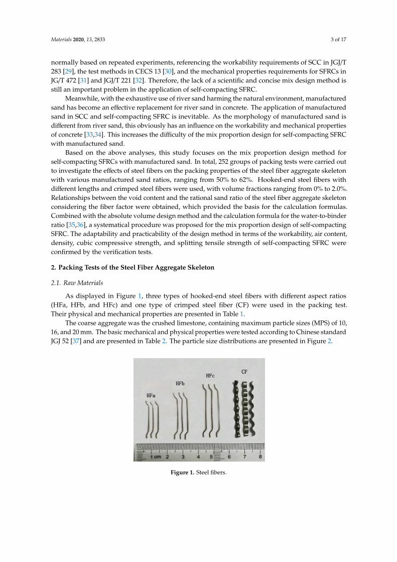
As displayed in Figure 1, three types of hooked-end steel fibers with different aspect ratios(HFa, HFb, and HFc) and one type of crimped steel fiber (CF) were used in the packing test.Their physical and mechanical properties are presented in Table 1.
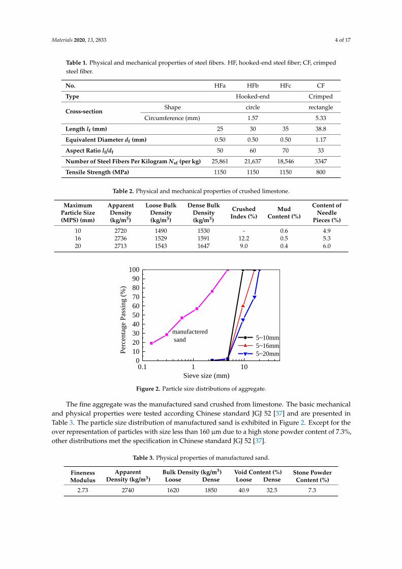
The coarse aggregate was the crushed limestone, containing maximum particle sizes (MPS) of 10,16, and 20 mm. The basic mechanical and physical properties were tested according to Chinese standardJGJ 52 [37] and are presented in Table 2. The particle size distributions are presented in Figure 2.
Materials 2020, 13, x FOR PEER REVIEW 3 of 16
EN 206-9 [28] proposes the mix design procedure for self-compacting SFRC. In China, the mix
design for self-compacting SFRC is normally based on repeated experiments, referencing the
workability requirements of SCC in JGJ/T 283 [29], the test methods in CECS 13 [30], and the
mechanical properties requirements for SFRCs in JG/T 472 [31] and JGJ/T 221 [32]. Therefore, the lack
of a scientific and concise mix design method is still an important problem in the application of
self-compacting SFRC.
Meanwhile, with the exhaustive use of river sand harming the natural environment,
manufactured sand has become an effective replacement for river sand in concrete. The application
of manufactured sand in SCC and self-compacting SFRC is inevitable. As the morphology of
manufactured sand is different from river sand, this obviously has an influence on the workability
and mechanical properties of concrete [33,34]. This increases the difficulty of the mix proportion
design for self-compacting SFRC with manufactured sand.
Based on the above analyses, this study focuses on the mix proportion design method for
self-compacting SFRCs with manufactured sand. In total, 252 groups of packing tests were carried
out to investigate the effects of steel fibers on the packing properties of the steel fiber aggregate
skeleton with various manufactured sand ratios, ranging from 50% to 62%. Hooked-end steel fibers
with different lengths and crimped steel fibers were used, with volume fractions ranging from 0% to
2.0%. Relationships between the void content and the rational sand ratio of the steel fiber aggregate
skeleton considering the fiber factor were obtained, which provided the basis for the calculation
formulas. Combined with the absolute volume design method and the calculation formula for the
water-to-binder ratio [35,36], a systematical procedure was proposed for the mix proportion design
of self-compacting SFRC. The adaptability and practicability of the design method in terms of the
workability, air content, density, cubic compressive strength, and splitting tensile strength of
self-compacting SFRC were confirmed by the verification tests.
2. Packing Tests of the Steel Fiber Aggregate Skeleton
2.1. Raw Materials
As displayed in Figure 1, three types of hooked-end steel fibers with different aspect ratios
(HFa, HFb, and HFc) and one type of crimped steel fiber (CF) were used in the packing test. Their
physical and mechanical properties are presented in Table 1.
Figure 1. Steel fibers.
Table 1. Physical and mechanical properties of steel fibers. HF, hooked-end steel fiber; CF, crimped
steel fiber.
No. HFa HFb HFc CF
Type Hooked-end Crimped
Cross-section Shape circle rectangle
Circumference (mm) 1.57 5.33
Figure 1. Steel fibers.
Materials 2020, 13, 2833 4 of 17
Table 1. Physical and mechanical properties of steel fibers. HF, hooked-end steel fiber; CF, crimpedsteel fiber.
No. HFa HFb HFc CF
Type Hooked-end Crimped
Cross-sectionShape circle rectangle
Circumference (mm) 1.57 5.33
Length lf (mm) 25 30 35 38.8
Equivalent Diameter df (mm) 0.50 0.50 0.50 1.17
Aspect Ratio lf/df 50 60 70 33
Number of Steel Fibers Per Kilogram Nsf (per kg) 25,861 21,637 18,546 3347
Tensile Strength (MPa) 1150 1150 1150 800
Table 2. Physical and mechanical properties of crushed limestone.
MaximumParticle Size(MPS) (mm)
ApparentDensity(kg/m3)
Loose BulkDensity(kg/m3)
Dense BulkDensity(kg/m3)
CrushedIndex (%)
MudContent (%)
Content ofNeedle
Pieces (%)
10 2720 1490 1530 - 0.6 4.916 2736 1529 1591 12.2 0.5 5.320 2713 1543 1647 9.0 0.4 6.0
Materials 2020, 13, x FOR PEER REVIEW 4 of 16
Length lf (mm) 25 30 35 38.8
Equivalent Diameter df (mm) 0.50 0.50 0.50 1.17
Aspect Ratio lf / df 50 60 70 33
Number of Steel Fibers Per Kilogram Nsf (per kg) 25861 21637 18546 3347
Tensile Strength (MPa) 1150 1150 1150 800
The coarse aggregate was the crushed limestone, containing maximum particle sizes (MPS) of
10, 16, and 20 mm. The basic mechanical and physical properties were tested according to Chinese
standard JGJ 52 [37] and are presented in Table 2. The particle size distributions are presented in
Figure 2.
Table 2. Physical and mechanical properties of crushed limestone.
Maximum
Particle Size
(MPS) (mm)
Apparent
Density
(kg/m3)
Loose Bulk
Density
(kg/m3)
Dense Bulk
Density
(kg/m3)
Crushed
Index (%)
Mud
Content (%)
Content of
Needle
Pieces (%)
10 2720 1490 1530 - 0.6 4.9
16 2736 1529 1591 12.2 0.5 5.3
20 2713 1543 1647 9.0 0.4 6.0
0.1 1 100
10
20
30
40
50
60
70
80
90
100
manufactered
sand 5~10mm
5~16mm
5~20mmPer
cen
tag
e P
assi
ng
(%
)
Sieve size (mm)
Figure 2. Particle size distributions of aggregate.
The fine aggregate was the manufactured sand crushed from limestone. The basic mechanical
and physical properties were tested according Chinese standard JGJ 52 [37] and are presented in
Table 3. The particle size distribution of manufactured sand is exhibited in Figure 2. Except for the
over representation of particles with size less than 160 μm due to a high stone powder content of
7.3%, other distributions met the specification in Chinese standard JGJ 52 [37].
Table 3. Physical properties of manufactured sand.
Fineness
Modulus
Apparent Density
(kg/m3)
Bulk Density (kg/m3) Void Content (%) Stone Powder
Content (%) Loose Dense Loose Dense
2.73 2740 1620 1850 40.9 32.5 7.3
2.2. Experimental Design
In this experiment, 252 groups of packing tests were designed. The volume fraction of steel
fiber (vf) ranged from 0 to 2.0% [38]. The sand ratio βs, expressed as in Equation (1), was the ratio of
manufactured sand to the sum of aggregates and steel fiber by mass. Corresponding to each steel
fiber volume fraction, the sand ratio ranged from 50% to 62%, with increments of 2%. Details of the
experimental design are presented in Table 4.
Figure 2. Particle size distributions of aggregate.
The fine aggregate was the manufactured sand crushed from limestone. The basic mechanicaland physical properties were tested according Chinese standard JGJ 52 [37] and are presented inTable 3. The particle size distribution of manufactured sand is exhibited in Figure 2. Except for theover representation of particles with size less than 160 µm due to a high stone powder content of 7.3%,other distributions met the specification in Chinese standard JGJ 52 [37].
Table 3. Physical properties of manufactured sand.
FinenessModulus
ApparentDensity (kg/m3)
Bulk Density (kg/m3) Void Content (%) Stone PowderContent (%)Loose Dense Loose Dense
2.73 2740 1620 1850 40.9 32.5 7.3
Materials 2020, 13, 2833 5 of 17
2.2. Experimental Design
In this experiment, 252 groups of packing tests were designed. The volume fraction of steel fiber(vf) ranged from 0 to 2.0% [38]. The sand ratio βs, expressed as in Equation (1), was the ratio ofmanufactured sand to the sum of aggregates and steel fiber by mass. Corresponding to each steelfiber volume fraction, the sand ratio ranged from 50% to 62%, with increments of 2%. Details of theexperimental design are presented in Table 4.
βs =ms
ms + mg + m f, (1)
mf = 7850vf, (2)
where ms, mg, and mf are the volumes of manufactured sand, coarse aggregate, and steel fiber inself-compacting SFRC.
Table 4. Experimental design.
TrialsSteel Fiber Sand Ratio
(%)MPS of Coarse Aggregate
(mm)Type Volume Fraction vf (%)
00-10 - 0 50, 52, 54, 56, 58, 60, 62 10
00-16 - 0 50, 52, 54, 56, 58, 60, 62 16
00-20 - 0 50, 52, 54, 56, 58, 60, 62 20
HFa-10 HFa 0.4, 0.8, 1.2, 1.6, 2.0 50, 52, 54, 56, 58, 60, 62 10
HFa-16 HFa 0.4, 0.8, 1.2, 1.6, 2.0 50, 52, 54, 56, 58, 60, 62 16
HFb-16 HFb 0.4, 0.8, 1.2, 1.6, 2.0 50, 52, 54, 56, 58, 60, 62 16
HFc-16 HFc 0.4, 0.8, 1.2, 1.6, 2.0 50, 52, 54, 56, 58, 60, 62 16
HFc-20 HFc 0.4, 0.8, 1.2, 1.6, 2.0 50, 52, 54, 56, 58, 60, 62 20
CF-16 CF 0.4, 0.8, 1.2, 1.6, 2.0 50, 52, 54, 56, 58, 60, 62 16
2.3. Test Method
The premise of the experimental design was to keep the total volume of steel fiber and aggregatesconstant. The packing test was similar to the test method for the bulk density of coarse aggregatesspecified in Chinese code JGJ 52 [37] and ASTM C29 [39]. The raw materials of the coarse and fineaggregates and the steel fiber were weighed into a 20 L mixture and then uniformly mixed together.By using a bucket with a volume of 10 L (0.01 m3), the mixture was filled in a free-falling manner toa height of 50 mm over the top of the bucket. After flattening the surface of the mixture by removingthe protruding portion of the bucket surface, the sample in the bucket was weighed as mm (kg).The bulk density ρbk (kg/m3) and the void content of the steel fiber aggregate skeleton VC wascalculated with Equations (3) and (4). Tests were repeated twice per group to reduce system error.
ρbk =mm
0.01, (3)
VC = 1−ρbk
ρa, (4)
where ρa is the apparent density of the steel fiber aggregate mixture, which is the sum of the apparentdensities of steel fiber, fine aggregate, and coarse aggregate by multiplying their own proportions inthe mixture.
Materials 2020, 13, 2833 6 of 17
3. Effects of Fiber Factor on the Void Content of the Steel Fiber Aggregate Skeleton and theOptimal Sand Ratio
3.1. Relationship between Fiber Factor and Void Content of Steel Fiber Aggregate Skeleton
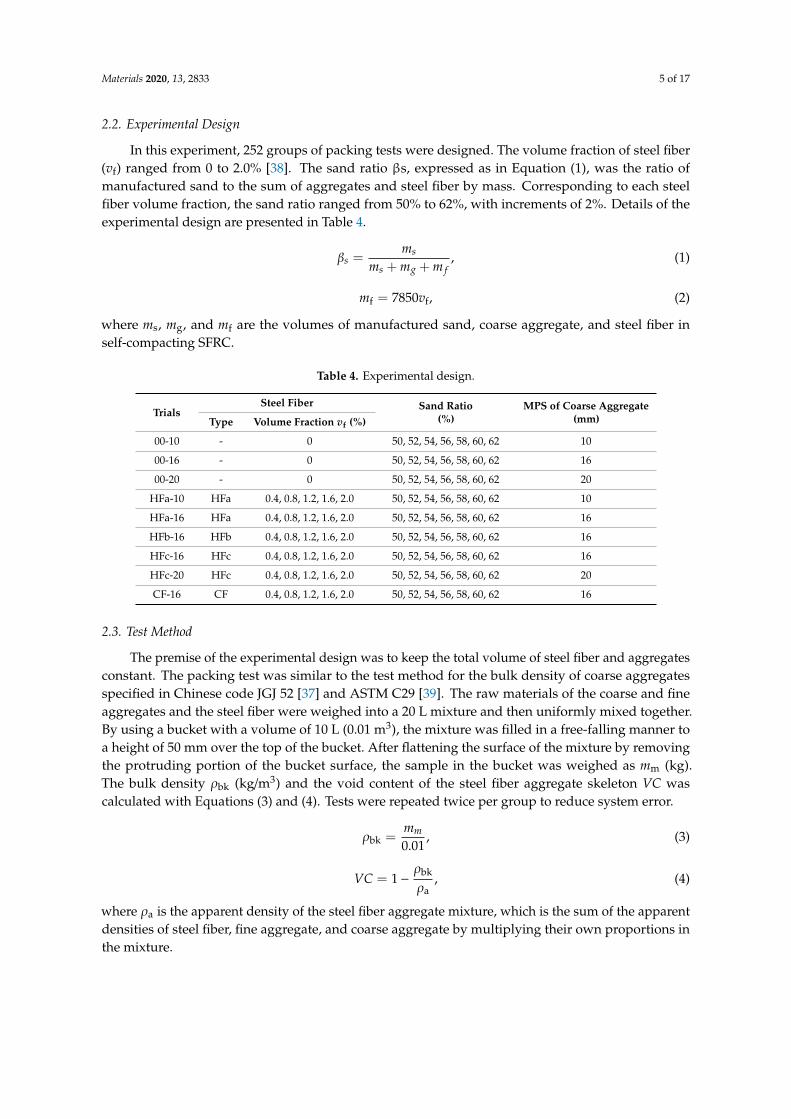
The bulk densities and void contents of the steel fiber aggregate skeleton are listed in Appendix ATable A1. Figure 3 shows the relationship of fiber factor λf and the void content VC of the steel fiberaggregate skeleton. Fiber factor λf is the product of the volume fraction vf with aspect ratio lf/df for thesteel fiber, i.e., λf = vf·lf/df. It can be seen that VC is linearly correlated with fiber factor λf for all testsamples. The relationship between VC and λf can be expressed as in Equation (5).
VC = (1 + αVCλf)VC0 (5)
where VC0 is the void content of the granular aggregate skeleton, which is related to the maximumparticle size and grading of the coarse aggregate [1]; aVC is a fitness parameter, which is listed in Table 5.Materials 2020, 13, x FOR PEER REVIEW 6 of 16
0.0 0.2 0.4 0.6 0.8 1.0 1.2 1.430
32
34
36
38
40
42
44
46
48
50 HFa-10 HFa-16 HFb-16
HFc-16 HFc-20
CF-16
Void
conte
nt
VC
(%
)
Fiber factorf
Figure 3. Changes of void content VC with a varying fiber factor λf.
VC f 01+VC VC (5)
where VC0 is the void content of the granular aggregate skeleton, which is related to the maximum
particle size and grading of the coarse aggregate [1]; aVC is a fitness parameter, which is listed in
Table 5.
Table 5. Statistical results of the parameter aVC.
Item HFa-10 HFa-16 HFb-16 HFc-16 HFc-20 CF-16
Fitness Number 42 42 42 42 42 42
Ratio of fiber length to MPS 2.500 1.563 1.875 2.188 1.750 2.425
Parameter αVC 0.227 0.275 0.291 0.267 0.265 0.329
Standard Error 0.004 0.005 0.003 0.004 0.004 0.007
Adjusted R-Square 0.953 0.946 0.987 0.974 0.968 0.943
Proposed Parameter αVC 0.27 0.33
When the MPS of the coarse aggregate was 10 mm, the fitness values of aVC (Table 5) indicated
that with the hooked-end steel fibers, VC showed a small increase with the increase of fiber factor λf,
while large increases were seen for VC when the MPS of the coarse aggregate measured 16 and 20
mm. Due to the larger specific surface area of the coarse aggregate with MPS = 10 mm, a larger
volume of binder paste was needed to achieve flowability for fresh self-compacting SFRC. Therefore,
for the steel fiber aggregate skeletons with MPS = 16 and 20 mm for the coarse aggregate, the value
of aVC was larger than the mean value of aVC = 0.27. Meanwhile, a large aVC value was obtained for
the steel fiber aggregate skeleton with the crimped steel fiber. There were many more voids
between the crimped steel fibers and aggregates due to their decreased contact areas. For the
proposed values of aVC, Figure 4 presents the good agreement between the tested and calculated
void contents of the steel fiber aggregate skeleton.
Figure 3. Changes of void content VC with a varying fiber factor λf.
Table 5. Statistical results of the parameter aVC.
Item HFa-10 HFa-16 HFb-16 HFc-16 HFc-20 CF-16
Fitness
Number 42 42 42 42 42 42
Ratio of fiber length to MPS 2.500 1.563 1.875 2.188 1.750 2.425
Parameter αVC 0.227 0.275 0.291 0.267 0.265 0.329
Standard Error 0.004 0.005 0.003 0.004 0.004 0.007
Adjusted R-Square 0.953 0.946 0.987 0.974 0.968 0.943
Proposed Parameter αVC 0.27 0.33
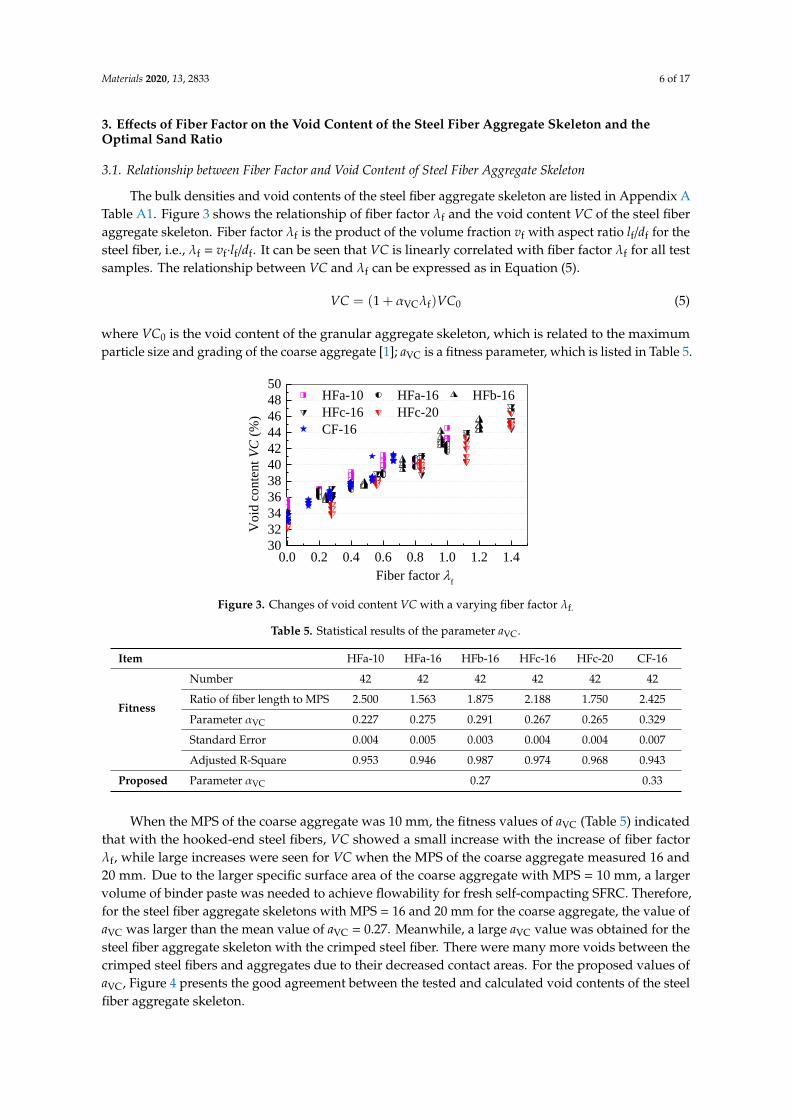
When the MPS of the coarse aggregate was 10 mm, the fitness values of aVC (Table 5) indicatedthat with the hooked-end steel fibers, VC showed a small increase with the increase of fiber factorλf, while large increases were seen for VC when the MPS of the coarse aggregate measured 16 and20 mm. Due to the larger specific surface area of the coarse aggregate with MPS = 10 mm, a largervolume of binder paste was needed to achieve flowability for fresh self-compacting SFRC. Therefore,for the steel fiber aggregate skeletons with MPS = 16 and 20 mm for the coarse aggregate, the value ofaVC was larger than the mean value of aVC = 0.27. Meanwhile, a large aVC value was obtained for thesteel fiber aggregate skeleton with the crimped steel fiber. There were many more voids between thecrimped steel fibers and aggregates due to their decreased contact areas. For the proposed values ofaVC, Figure 4 presents the good agreement between the tested and calculated void contents of the steelfiber aggregate skeleton.
Materials 2020, 13, 2833 7 of 17
The binder paste volume in the concrete mixture could be divided into two parts, namely thevoid volume of the granular skeleton and the margin binder paste [1]. The former is used for filling thevoid of the granular skeleton, while the latter is used for lubricating the granular skeleton in freshconcrete to maintain suitable workability. Assuming the volume ratio of the margin binder paste to thetotal binder paste is constant, the rational volume content BP of binder paste for self-compacting SFRCcompared with reference SCC can be expressed as Equation (6):
BP = (1 + αVCλf)BP0, (6)
where BP0 is the volume content of binder paste for reference self-compacting concrete without steelfiber (SCC).Materials 2020, 13, x FOR PEER REVIEW 7 of 16
32 36 40 44 4832
36
40
44
48 HFa-10
HFa-16
HFb-16
HFc-16
HFc-20
CF-16
Cal
cula
ted
VC
(%)
Tested VC(%)
Figure 4. Comparison of tested and calculated values of void content VC.
The binder paste volume in the concrete mixture could be divided into two parts, namely the
void volume of the granular skeleton and the margin binder paste [1]. The former is used for filling
the void of the granular skeleton, while the latter is used for lubricating the granular skeleton in
fresh concrete to maintain suitable workability. Assuming the volume ratio of the margin binder
paste to the total binder paste is constant, the rational volume content BP of binder paste for
self-compacting SFRC compared with reference SCC can be expressed as Equation (6):
VC f 01+BP BP , (6)
where BP0 is the volume content of binder paste for reference self-compacting concrete without
steel fiber (SCC).
Ignoring the volume changes for water and binder materials in the mixing process of
self-compacting SFRC, the volume fraction of the binder paste is the sum of the volume fractions of
the water and binder materials. Thus, Equation (6) is translated into Equation (7):
VC fw b w0 b0+ +1+V VV V , (7)
where Vw and Vb are the volume fractions of water and binder for self-compacting SFRC; Vw0 and
Vb0 are the volume fractions of water and binder for reference SCC.
Ignoring the contribution of steel fiber to the compressive strength of self-compacting SFRC,
the water-to-binder ratio by mass of self-compacting SFRC is the same as the referenced SCC and
the same goes for the water-to-binder ratio by volume. That is,
w w0
b b0
V V
V V , (8)
combined with Equations (7) and (8), the volume fractions of binder materials can be written as:
VC fb b01+V V , (9)
By dividing the density of the binder material in both sides of Equation (9), the binder content
of self-compacting SFRC can be expressed as:
VC fbf b01+m m , (10)
where mbf is the rational binder content of self-compacting SFRC and mb0 is the binder content of
reference SCC.
3.2. The Optimal Sand Ratios
The variations of void content VC of the steel fiber aggregate skeleton with sand ratio βf are
shown in Figure 5. VC slightly decreased with increases of the sand ratio, while the fluctuation
Figure 4. Comparison of tested and calculated values of void content VC.
Ignoring the volume changes for water and binder materials in the mixing process ofself-compacting SFRC, the volume fraction of the binder paste is the sum of the volume fractions of thewater and binder materials. Thus, Equation (6) is translated into Equation (7):
Vw + Vb = (1 + αVCλf)(Vw0 + Vb0), (7)
where Vw and Vb are the volume fractions of water and binder for self-compacting SFRC; Vw0 and Vb0
are the volume fractions of water and binder for reference SCC.Ignoring the contribution of steel fiber to the compressive strength of self-compacting SFRC,
the water-to-binder ratio by mass of self-compacting SFRC is the same as the referenced SCC and thesame goes for the water-to-binder ratio by volume. That is,
Vw
Vb=
Vw0
Vb0, (8)
combined with Equations (7) and (8), the volume fractions of binder materials can be written as:
Vb = (1 + αVCλf)Vb0, (9)
By dividing the density of the binder material in both sides of Equation (9), the binder content ofself-compacting SFRC can be expressed as:
mbf = (1 + αVCλf)mb0, (10)
Materials 2020, 13, 2833 8 of 17
where mbf is the rational binder content of self-compacting SFRC and mb0 is the binder content ofreference SCC.
3.2. The Optimal Sand Ratios
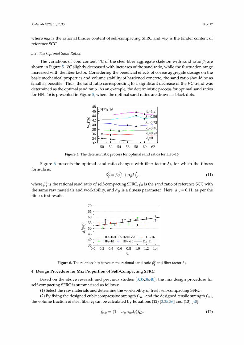
The variations of void content VC of the steel fiber aggregate skeleton with sand ratio βf areshown in Figure 5. VC slightly decreased with increases of the sand ratio, while the fluctuation rangeincreased with the fiber factor. Considering the beneficial effects of coarse aggregate dosage on thebasic mechanical properties and volume stability of hardened concrete, the sand ratio should be assmall as possible. Thus, the sand ratio corresponding to a significant decrease of the VC trend wasdetermined as the optimal sand ratio. As an example, the deterministic process for optimal sand ratiosfor HFb-16 is presented in Figure 5, where the optimal sand ratios are drawn as black dots.
Materials 2020, 13, x FOR PEER REVIEW 8 of 16
range increased with the fiber factor. Considering the beneficial effects of coarse aggregate dosage
on the basic mechanical properties and volume stability of hardened concrete, the sand ratio should
be as small as possible. Thus, the sand ratio corresponding to a significant decrease of the VC trend
was determined as the optimal sand ratio. As an example, the deterministic process for optimal
sand ratios for HFb-16 is presented in Figure 5, where the optimal sand ratios are drawn as black
dots.
50 52 54 56 58 60 6232
34
36
38
40
42
44
46
48
f=1.2
f=0
f=0.96
f=0.72
f=0.48V
C(%
)
Sand ratios f (%)
HFb-16
f=0.24
Figure 5. The deterministic process for optimal sand ratios for HFb-16.
Figure 6 presents the optimal sand ratio changes with fiber factor λf, for which the fitness
formula is:
0
ff 01+ , (11)
where β0
f is the rational sand ratio of self-compacting SFRC, β0 is the sand ratio of reference SCC
with the same raw materials and workability, and αβ is a fitness parameter. Here, αβ = 0.11, as per
the fitness test results.
0.0 0.2 0.4 0.6 0.8 1.0 1.2 1.435
40
45
50
55
60
65
70
HFa-16/HFb-16/HFc-16 CF-16
HFa-10 HFc-20 Eq. 11
f0(%
)
f
Figure 6. The relationship between the rational sand ratio β0
f and fiber factor λf.
4. Design Procedure for Mix Proportion of Self-Compacting SFRC
Based on the above research and previous studies [3,35,36,40], the mix design procedure for
self-compacting SFRC is summarized as follows:
(1) Select the raw materials and determine the workability of fresh self-compacting SFRC;
(2) By fixing the designed cubic compressive strength fcu,0 and the designed tensile strength fft,0,
the volume fraction of steel fiber vf can be calculated by Equations (12) [3,35,36] and (13) [40]:
tb te fft,0 t,01+f f , (12)
2/3cu,0
t,0
( )0.65 8
3
ff
, (13)
where ft,0 is the tensile strength of reference SCC with the same water-to-binder ratio, αte is the
coefficient related to the effective fiber distribution, αtb is a coefficient colligated the other factors
Figure 5. The deterministic process for optimal sand ratios for HFb-16.
Figure 6 presents the optimal sand ratio changes with fiber factor λf, for which the fitnessformula is:
β0f = β0
(1 + αβλf
), (11)
where β0f is the rational sand ratio of self-compacting SFRC, β0 is the sand ratio of reference SCC with
the same raw materials and workability, and αβ is a fitness parameter. Here, αβ = 0.11, as per thefitness test results.
Materials 2020, 13, x FOR PEER REVIEW 8 of 16
range increased with the fiber factor. Considering the beneficial effects of coarse aggregate dosage
on the basic mechanical properties and volume stability of hardened concrete, the sand ratio should
be as small as possible. Thus, the sand ratio corresponding to a significant decrease of the VC trend
was determined as the optimal sand ratio. As an example, the deterministic process for optimal
sand ratios for HFb-16 is presented in Figure 5, where the optimal sand ratios are drawn as black
dots.
50 52 54 56 58 60 6232
34
36
38
40
42
44
46
48
f=1.2
f=0
f=0.96
f=0.72
f=0.48V
C(%
)
Sand ratios f (%)
HFb-16
f=0.24
Figure 5. The deterministic process for optimal sand ratios for HFb-16.
Figure 6 presents the optimal sand ratio changes with fiber factor λf, for which the fitness
formula is:
0
ff 01+ , (11)
where β0
f is the rational sand ratio of self-compacting SFRC, β0 is the sand ratio of reference SCC
with the same raw materials and workability, and αβ is a fitness parameter. Here, αβ = 0.11, as per
the fitness test results.
0.0 0.2 0.4 0.6 0.8 1.0 1.2 1.435
40
45
50
55
60
65
70
HFa-16/HFb-16/HFc-16 CF-16
HFa-10 HFc-20 Eq. 11
f0(%
)
f
Figure 6. The relationship between the rational sand ratio β0
f and fiber factor λf.
4. Design Procedure for Mix Proportion of Self-Compacting SFRC
Based on the above research and previous studies [3,35,36,40], the mix design procedure for
self-compacting SFRC is summarized as follows:
(1) Select the raw materials and determine the workability of fresh self-compacting SFRC;
(2) By fixing the designed cubic compressive strength fcu,0 and the designed tensile strength fft,0,
the volume fraction of steel fiber vf can be calculated by Equations (12) [3,35,36] and (13) [40]:
tb te fft,0 t,01+f f , (12)
2/3cu,0
t,0
( )0.65 8
3
ff
, (13)
where ft,0 is the tensile strength of reference SCC with the same water-to-binder ratio, αte is the
coefficient related to the effective fiber distribution, αtb is a coefficient colligated the other factors
Figure 6. The relationship between the rational sand ratio β0f and fiber factor λf.
4. Design Procedure for Mix Proportion of Self-Compacting SFRC
Based on the above research and previous studies [3,35,36,40], the mix design procedure forself-compacting SFRC is summarized as follows:
(1) Select the raw materials and determine the workability of fresh self-compacting SFRC;(2) By fixing the designed cubic compressive strength f cu,0 and the designed tensile strength f ft,0,
the volume fraction of steel fiber vf can be calculated by Equations (12) [3,35,36] and (13) [40]:
fft,0 = (1 + αtbαteλf) ft,0, (12)
Materials 2020, 13, 2833 9 of 17
ft,0 =(0.65 fcu,0 − 8)2/3
3, (13)
where f t,0 is the tensile strength of reference SCC with the same water-to-binder ratio, αte is thecoefficient related to the effective fiber distribution, αtb is a coefficient colligated the other factorsinfluencing the bridging effect of steel fibers on tensile strength of self-compacting SFRC.
(3) The water-to-binder ratio w/b of self-compacting SFRC can be calculated by Equation (14) [41]:
w/b =αa fb
fcu,0 + αaαb fb, (14)
where αa and αb are coefficients mainly related to the type of coarse aggregate and concrete; αa = 0.270and αb = −0.522; f b is the compressive strength of the binder material at curing age of 28 days.
(4) By using the absolute volume method, the detailed mix proportion of reference SCC with thesame w/b as the self-compacting SFRC can be determined. Packing tests for aggregates with differentsand ratios are conducted to obtain the optimal sand ratio β0 and volume fraction for the coarseaggregate and fine aggregate;
(5) The binder content of self-compacting SFRC mbf is fixed using Equation (10). Thus, the dosagesof cement and mineral admixtures can be calculated;
(6) Calculate the water content mwf using Equation (15):
mwf =mbf
w/b, (15)
(7) Calculate the rational sand ratio β0f of self-compacting SFRC using Equation (11);
(8) Calculate the dosages of fine aggregate and coarse aggregate msf and mgf using the absolutevolume method, as follows:
mbf
ρb+
mwf
ρw+
msf
ρs+
mgf
ρg+ vf + 0.01α = 1, (16)
where ρb, ρw, ρs, and ρg are the densities of binder materials, water, fine aggregate, and coarse aggregate,respectively, expressed as kg/m3; α is the air content of fresh self-compacting SFRC, expressed as a %.
(9) Determine the superplasticizer dosage based on the assessment of the required performance.Trial mixes with different dosages of superplasticizer should be carried out.
The workability and mechanical properties of self-compacting SFRC should satisfy the constructionrequirements. Otherwise, proper adjustments should be made until satisfactory results are achieved.
5. Verification for the Design of the Mix Proportions of Self-Compacting SFRC
5.1. Experimental Design
Eight groups of mixes were experimentally studied to verify the rationality of the mix proportiondesign method of self-compacting SFRC. The main parameters were the water-to-binder ratio w/b = 0.31,and the volume fractions of steel fiber vf = 0%, 0.4%, 0.8%, 1.2%, 1.4% and 1.6%. As the same as thepacking test of steel fiber-aggregate skeleton, the hooked-end steel fibers named as HFa, HFb and HFc,the crushed limestone with a maximum particle size of 16mm, and the manufactured sand were used.Grade P.O. 42.5 ordinary silicate cement and fly ash were used as the binder materials. Their physicaland mechanical properties are tested according Chinese standard GB 175 [42] and GB/T51003 [43] andlisted in Table 6, respectively. Tap water and PCA-I polycarboxylic high performance water-reducerwith solid content as 24.1% and water-reducing rate greater than 28% were also used in this experiment.The designed strengths and detailed mix proportion of self-compacting SFRC are listed in Table 7.
Materials 2020, 13, 2833 10 of 17
Table 6. Physical and mechanical properties of cement and fly ash.
Cement
Density(kg/m3)
Fluidity ofcement mortar
(mm)
Water requirement ofnormal consistency
(%)
Setting time (min) Flexural strength(MPa)
Compressivestrength f ce (MPa)
Initial Final 3d 28d 3d 28d
3085 137 26.4 160 245 6.17 9.43 29.4 54.7
Fly Ash
Density(kg/m3)
Fineness(45µm, %)
Water demand ratio(%)
Strength activityindex (%) Loss on ignition (%) Class
2349 10 98 80.9 1.9 II
Table 7. Detailed mix proportion of self-compacting steel-fiber-reinforced concrete (SFRC).
Mixtures Reference SCC HFb04 HFb08 HFb12 HFb14 HFb16 HFa12 HFc12
Designed compressivestrength f cu,0 (MPa) 50 50 50 50 50 50 50 50
Designed tensile strengthf ft,0 (MPa) 2.93 3.28 3.63 3.98 4.16 4.34 3.81 4.16
w/b 0.31 0.31 0.31 0.31 0.31 0.31 0.31 0.31Sand ratio βs (%,by mass) 50 52 54 56 57 58 55 57Fly ash content (%,by mass) 30 30 30 30 30 30 30 30
Steel fiberType - HFb HFb HFb HFb HFb HFa HFcvf (%) 0 0.4 0.8 1.2 1.4 1.6 1.2 1.2λf 0 0.24 0.48 0.72 0.84 0.96 0.6 0.84
Water (kg/m3) 192 201 210 219 223 228 214 223Cement (kg/m3) 433 454 474 494 504 514 484 504Fly ash (kg/m3) 186 194 203 214 216 220 207 216Coarse aggregate (kg/m3) 751 675 601 527 491 455 553 502Manufactured sand(kg/m3) 751 763 774 783 788 792 784 782Water reducer (kg/m3) 5.57 5.51 5.42 5.30 5.40 5.51 5.19 5.40Steel fiber (kg/m3) 0 31.4 62.8 94.2 109.9 125.6 94.2 94.2
5.2. Performances of Fresh Self-Compacting SFRC
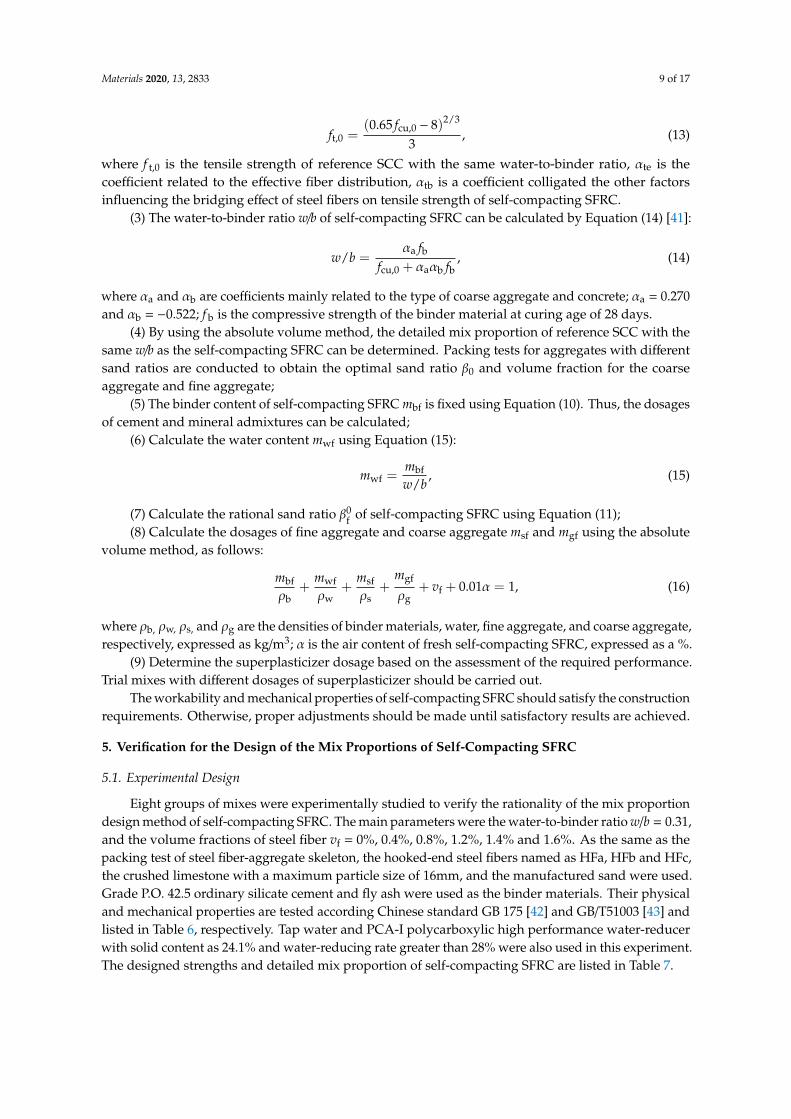
The air content of fresh self-compacting SFRC was tested using the pressure method withoutvibratory compaction, referring to Chinese code GB/T 50080 [44] and ASTM C231 [45]. As presented inFigure 7, the air content increased with the volume fraction of the steel fiber. The air content of HF-16was about 76% higher than that of reference SCC. The addition of more steel fibers would introducemore air into the fresh self-compacting SFRC. This is consistent with the studies of Ding and Yang [46]and Miao et al [47].
Materials 2020, 13, x FOR PEER REVIEW 10 of 16
(kg/m3) cement
mortar(mm)
normal consistency
(%)
(min) strength
(MPa)
strength fce
(MPa)
Initial Final 3d 28d 3d 28d
3085 137 26.4 160 245 6.17 9.43 29.4 54.7
Fly Ash
Density
(kg/m3)
Fineness
(45μm, %)
Water demand
ratio (%)
Strength activity
index (%)
Loss on ignition
(%) Class
2349 10 98 80.9 1.9 II
Table 7. Detailed mix proportion of self-compacting steel-fiber-reinforced concrete (SFRC).
Mixtures Reference SCC HFb04 HFb08 HFb12 HFb14 HFb16 HFa12 HFc12
Designed compressive strength
fcu,0(MPa) 50 50 50 50 50 50 50 50
Designed tensile strength fft,0 (MPa) 2.93 3.28 3.63 3.98 4.16 4.34 3.81 4.16
w/b 0.31 0.31 0.31 0.31 0.31 0.31 0.31 0.31
Sand ratioβs(%,by mass) 50 52 54 56 57 58 55 57
Fly ash content (%,by mass) 30 30 30 30 30 30 30 30
Steel fiber
Type - HFb HFb HFb HFb HFb HFa HFc
vf(%) 0 0.4 0.8 1.2 1.4 1.6 1.2 1.2
λf 0 0.24 0.48 0.72 0.84 0.96 0.6 0.84
Water (kg/m3) 192 201 210 219 223 228 214 223
Cement (kg/m3) 433 454 474 494 504 514 484 504
Fly ash (kg/m3) 186 194 203 214 216 220 207 216
Coarse aggregate (kg/m3) 751 675 601 527 491 455 553 502
Manufactured sand(kg/m3) 751 763 774 783 788 792 784 782
Water reducer (kg/m3) 5.57 5.51 5.42 5.30 5.40 5.51 5.19 5.40
Steel fiber (kg/m3) 0 31.4 62.8 94.2 109.9 125.6 94.2 94.2
5.2. Performances of Fresh Self-Compacting SFRC
The air content of fresh self-compacting SFRC was tested using the pressure method without
vibratory compaction, referring to Chinese code GB/T 50080 [44] and ASTM C231 [45]. As presented
in Figure 7, the air content increased with the volume fraction of the steel fiber. The air content of
HF-16 was about 76% higher than that of reference SCC. The addition of more steel fibers would
introduce more air into the fresh self-compacting SFRC. This is consistent with the studies of Ding
and Yang [46] and Miao et al [47].
0
1
2
3
4
5
6
7
HFc12HFa12
HFb16
HFb14
HFb12HFb08
HFb04
Air
co
nte
nt (
%)
Fresh Self-compacting SFRC
SCC
Figure 7. Air content of fresh self-compacting SFRC.
The workability of fresh self-compacting SFRC was evaluated by slump flow and flow time
T500 tests, in accordance with Chinese standard JGJ/T 283 [29], which is identical to ASTM C1611 [48]
and ASTM C 1621 [49]. The test results are presented in Table 8 and the pictures for the slump flow
test are shown in Figure 8. The slump flow and flow time T500 ranged within 560–685 mm and
Figure 7. Air content of fresh self-compacting SFRC.
Materials 2020, 13, 2833 11 of 17
The workability of fresh self-compacting SFRC was evaluated by slump flow and flow time T500
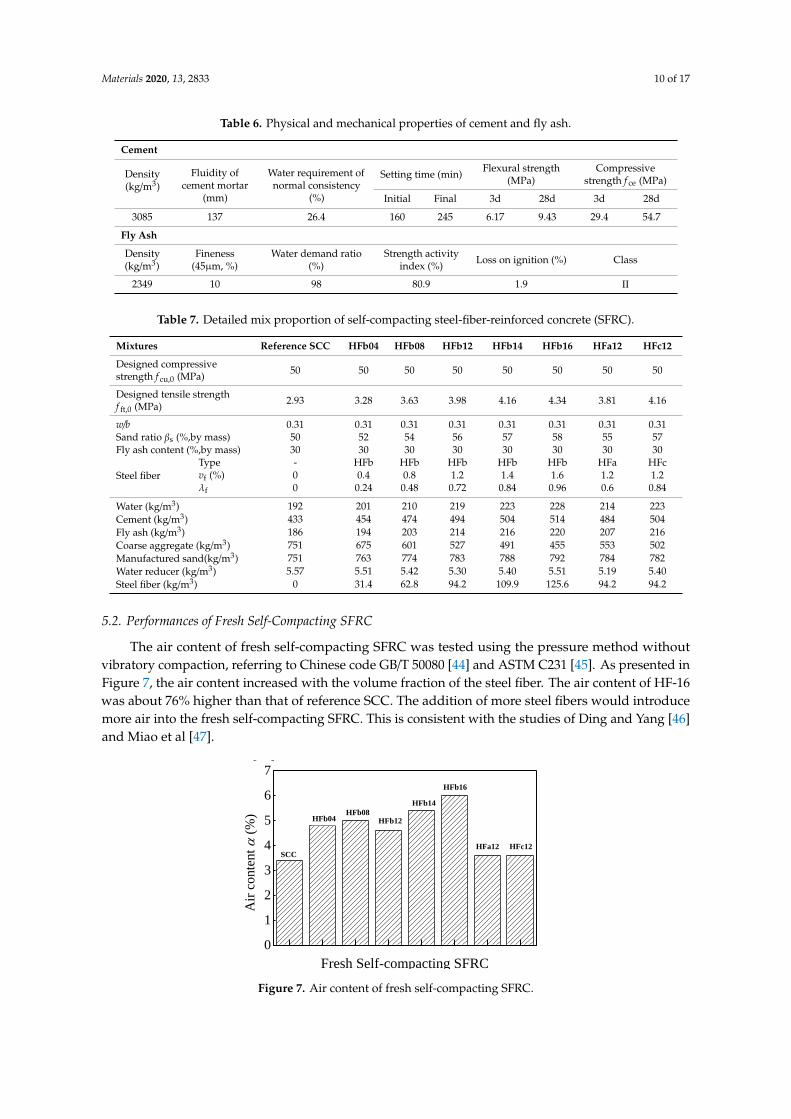
tests, in accordance with Chinese standard JGJ/T 283 [29], which is identical to ASTM C1611 [48] andASTM C 1621 [49]. The test results are presented in Table 8 and the pictures for the slump flow test areshown in Figure 8. The slump flow and flow time T500 ranged within 560–685 mm and 4.33–6.71 s,respectively. For self-compacting SFRC with HFb, the slump flow values were relatively stable atvf = 0.4–1.4%, decreasing to vf = 1.6%. In the same condition at vf = 1.2%, the slump flow decreasedslightly with the increased fiber length. In general, the slump flow of self-compacting SFRC fits thefilling ability level SF1 (slump flow = 550–655mm) or level SF2 (slump flow = 660–755mm), while T500
fits the the filling ability level VS1 (2 s ≤ T500 ≤ 8 s). This means that the fresh self-compacting SFRC issuitable for concrete structures and conventional reinforced concrete structures [29].
Table 8. Test results for fresh self-compacting SFRC.
Test TypeExperiment No.
SCC HFb04 HFb08 HFb12 HFb14 HFb16 HFa12 HFc12
Slump-flow (mm) 655 685 635 660 665 595 630 560
T500 (s) 5.38 5.36 4.44 5.4 6.28 6.37 4.33 6.71
Materials 2020, 13, x FOR PEER REVIEW 11 of 16
4.33–6.71s, respectively. For self-compacting SFRC with HFb, the slump flow values were relatively
stable at vf = 0.4–1.4%, decreasing to vf = 1.6%. In the same condition at vf = 1.2%, the slump flow
decreased slightly with the increased fiber length. In general, the slump flow of self-compacting
SFRC fits the filling ability level SF1 (slump flow = 550–655mm) or level SF2 (slump flow =
660–755mm), while T500 fits the the filling ability level VS1 (2 s ≤ T500 ≤ 8 s). This means that the fresh
self-compacting SFRC is suitable for concrete structures and conventional reinforced concrete
structures [29].
Table 8. Test results for fresh self-compacting SFRC.
Test Type Experiment No.
SCC HFb04 HFb08 HFb12 HFb14 HFb16 HFa12 HFc12
Slump-flow (mm) 655 685 635 660 665 595 630 560
T500 (s) 5.38 5.36 4.44 5.4 6.28 6.37 4.33 6.71
(a) (b) (c) (d)
(e) (f) (f) (h)
Figure 8. Pictures of slump flow tests. (a) concrete cake of reference SCC, (b) concrete cake of HFb04,
(c) concrete cake of HFb08, (d) concrete cake of HFb12, (e) concrete cake of HFb14, (f) concrete cake
of HFb16, (g) concrete cake of HFa12, (h) concrete cake of HFc12.
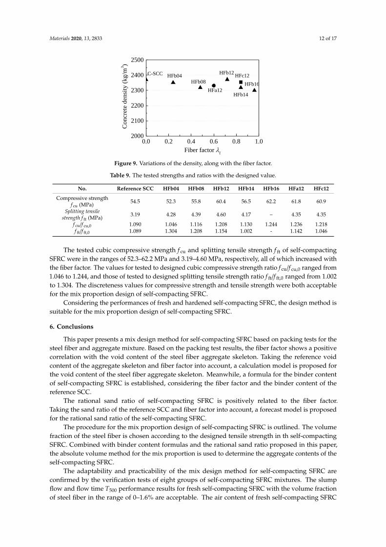
5.3. Density of Self-Compacting SFRC
Density is a macro index evaluating the compactness of hardened concrete. Figure 9 displays
the variations of the density of hardened self-compacting SFRC, along with fiber factor λf. The
density ratios of self-compacting SFRC to reference SCC were in the range of 97.0–100.1%. The
addition of steel fiber showed little influence on the compactness of hardened self-compacting
SFRC in this experiment, meaning that satisfactory compactness was obtained using the proposed
mix design method for self-compacting SFRC.
0.0 0.2 0.4 0.6 0.8 1.02000
2100
2200
2300
2400
2500
HFc12
HFa12
HFb16
HFb14
HFb12
HFb08
Co
ncr
ete
den
sity
(k
g/m
3)
Fiber factor f
C-SCC HFb04
Figure 8. Pictures of slump flow tests. (a) concrete cake of reference SCC, (b) concrete cake of HFb04,(c) concrete cake of HFb08, (d) concrete cake of HFb12, (e) concrete cake of HFb14, (f) concrete cake ofHFb16, (g) concrete cake of HFa12, (h) concrete cake of HFc12.
5.3. Density of Self-Compacting SFRC
Density is a macro index evaluating the compactness of hardened concrete. Figure 9 displays thevariations of the density of hardened self-compacting SFRC, along with fiber factor λf. The densityratios of self-compacting SFRC to reference SCC were in the range of 97.0–100.1%. The additionof steel fiber showed little influence on the compactness of hardened self-compacting SFRC in thisexperiment, meaning that satisfactory compactness was obtained using the proposed mix designmethod for self-compacting SFRC.
5.4. Mechanical Properties of Self-Compacting SFRC
The cubic compressive strength f cu and splitting tensile strength f ft of self-compacting SFRC weretested at 28 days using cubic specimens with dimensions of 150 mm, according to the specifications ofChinese Standard GB/T50081 [50], which is identical to British Standards BS EN 12390-3 [51] and BSEN12390-6 [52]. The test results are presented in Table 9.
Materials 2020, 13, 2833 12 of 17
Materials 2020, 13, x FOR PEER REVIEW 11 of 16
4.33–6.71s, respectively. For self-compacting SFRC with HFb, the slump flow values were relatively
stable at vf = 0.4–1.4%, decreasing to vf = 1.6%. In the same condition at vf = 1.2%, the slump flow
decreased slightly with the increased fiber length. In general, the slump flow of self-compacting
SFRC fits the filling ability level SF1 (slump flow = 550–655mm) or level SF2 (slump flow =
660–755mm), while T500 fits the the filling ability level VS1 (2 s ≤ T500 ≤ 8 s). This means that the fresh
self-compacting SFRC is suitable for concrete structures and conventional reinforced concrete
structures [29].
Table 8. Test results for fresh self-compacting SFRC.
Test Type Experiment No.
SCC HFb04 HFb08 HFb12 HFb14 HFb16 HFa12 HFc12
Slump-flow (mm) 655 685 635 660 665 595 630 560
T500 (s) 5.38 5.36 4.44 5.4 6.28 6.37 4.33 6.71
(a) (b) (c) (d)
(e) (f) (f) (h)
Figure 8. Pictures of slump flow tests. (a) concrete cake of reference SCC, (b) concrete cake of HFb04,
(c) concrete cake of HFb08, (d) concrete cake of HFb12, (e) concrete cake of HFb14, (f) concrete cake
of HFb16, (g) concrete cake of HFa12, (h) concrete cake of HFc12.
5.3. Density of Self-Compacting SFRC
Density is a macro index evaluating the compactness of hardened concrete. Figure 9 displays
the variations of the density of hardened self-compacting SFRC, along with fiber factor λf. The
density ratios of self-compacting SFRC to reference SCC were in the range of 97.0–100.1%. The
addition of steel fiber showed little influence on the compactness of hardened self-compacting
SFRC in this experiment, meaning that satisfactory compactness was obtained using the proposed
mix design method for self-compacting SFRC.
0.0 0.2 0.4 0.6 0.8 1.02000
2100
2200
2300
2400
2500
HFc12
HFa12
HFb16
HFb14
HFb12
HFb08
Concr
ete
den
sity
(kg/m
3)
Fiber factor f
C-SCC HFb04
Figure 9. Variations of the density, along with the fiber factor.
Table 9. The tested strengths and ratios with the designed value.
No. Reference SCC HFb04 HFb08 HFb12 HFb14 HFb16 HFa12 HFc12
Compressive strengthf cu (MPa) 54.5 52.3 55.8 60.4 56.5 62.2 61.8 60.9
Splitting tensilestrength f ft (MPa) 3.19 4.28 4.39 4.60 4.17 – 4.35 4.35
f cu/f cu,0 1.090 1.046 1.116 1.208 1.130 1.244 1.236 1.218f ft/f ft,0 1.089 1.304 1.208 1.154 1.002 - 1.142 1.046
The tested cubic compressive strength f cu and splitting tensile strength f ft of self-compactingSFRC were in the ranges of 52.3–62.2 MPa and 3.19–4.60 MPa, respectively, all of which increased withthe fiber factor. The values for tested to designed cubic compressive strength ratio f cu/f cu,0 ranged from1.046 to 1.244, and those of tested to designed splitting tensile strength ratio f ft/f ft,0 ranged from 1.002to 1.304. The discreteness values for compressive strength and tensile strength were both acceptablefor the mix proportion design of self-compacting SFRC.
Considering the performances of fresh and hardened self-compacting SFRC, the design method issuitable for the mix proportion design of self-compacting SFRC.
6. Conclusions
This paper presents a mix design method for self-compacting SFRC based on packing tests for thesteel fiber and aggregate mixture. Based on the packing test results, the fiber factor shows a positivecorrelation with the void content of the steel fiber aggregate skeleton. Taking the reference voidcontent of the aggregate skeleton and fiber factor into account, a calculation model is proposed forthe void content of the steel fiber aggregate skeleton. Meanwhile, a formula for the binder contentof self-compacting SFRC is established, considering the fiber factor and the binder content of thereference SCC.
The rational sand ratio of self-compacting SFRC is positively related to the fiber factor.Taking the sand ratio of the reference SCC and fiber factor into account, a forecast model is proposedfor the rational sand ratio of the self-compacting SFRC.
The procedure for the mix proportion design of self-compacting SFRC is outlined. The volumefraction of the steel fiber is chosen according to the designed tensile strength in th self-compactingSFRC. Combined with binder content formulas and the rational sand ratio proposed in this paper,the absolute volume method for the mix proportion is used to determine the aggregate contents of theself-compacting SFRC.
The adaptability and practicability of the mix design method for self-compacting SFRC areconfirmed by the verification tests of eight groups of self-compacting SFRC mixtures. The slumpflow and flow time T500 performance results for fresh self-compacting SFRC with the volume fractionof steel fiber in the range of 0–1.6% are acceptable. The air content of fresh self-compacting SFRC
Materials 2020, 13, 2833 13 of 17
increases with the fiber factor. The tested compressive and splitting tensile strengths increase with thefiber factor, agreeing well with the designed values.
Author Contributions: Methodology, X.D. and M.Z., and J.L.; investigation and data curation, X.D., P.S., and C.L;writing—original draft preparation, X.D. and M.Z.; writing—review and funding acquisition, X.D., J.L., and C.L.All authors have read and agreed to the published version of the manuscript.
Funding: This research was funded by the Key Scientific and Technological Research Project of University in Henan,China (grant numbers 20A560015 and 17A560025), Attracting Foreign Talents Fund of Henan, China (grant numberYWZ2018-6-HS2), State Key Research and Development Plan, China (grant number 2017YFC0703904), andInnovative Sci-Tech Team of Eco-building Material and Structural Engineering of Henan Province, China(grant number YKRZ-6-066).
Conflicts of Interest: The authors declare no conflict of interest.
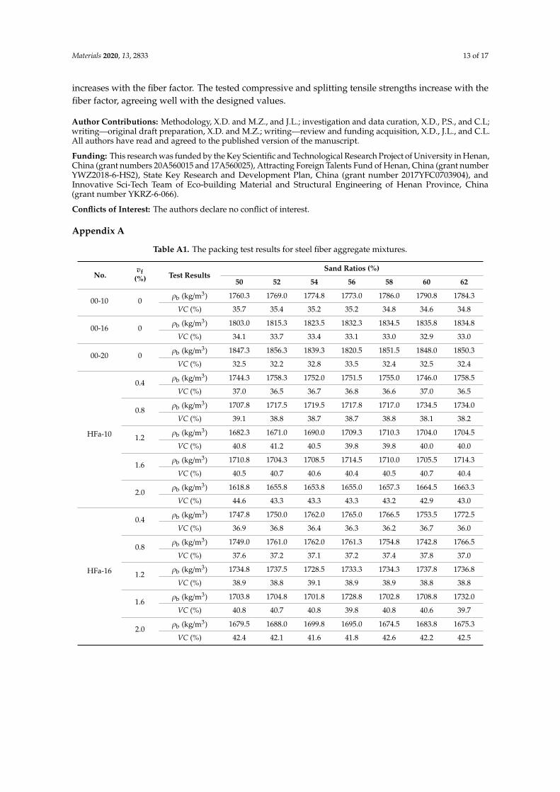
Appendix A
Table A1. The packing test results for steel fiber aggregate mixtures.
No.vf
(%) Test ResultsSand Ratios (%)
50 52 54 56 58 60 62
00-10 0ρb (kg/m3) 1760.3 1769.0 1774.8 1773.0 1786.0 1790.8 1784.3
VC (%) 35.7 35.4 35.2 35.2 34.8 34.6 34.8
00-16 0ρb (kg/m3) 1803.0 1815.3 1823.5 1832.3 1834.5 1835.8 1834.8
VC (%) 34.1 33.7 33.4 33.1 33.0 32.9 33.0
00-20 0ρb (kg/m3) 1847.3 1856.3 1839.3 1820.5 1851.5 1848.0 1850.3
VC (%) 32.5 32.2 32.8 33.5 32.4 32.5 32.4
HFa-10
0.4ρb (kg/m3) 1744.3 1758.3 1752.0 1751.5 1755.0 1746.0 1758.5
VC (%) 37.0 36.5 36.7 36.8 36.6 37.0 36.5
0.8ρb (kg/m3) 1707.8 1717.5 1719.5 1717.8 1717.0 1734.5 1734.0
VC (%) 39.1 38.8 38.7 38.7 38.8 38.1 38.2
1.2ρb (kg/m3) 1682.3 1671.0 1690.0 1709.3 1710.3 1704.0 1704.5
VC (%) 40.8 41.2 40.5 39.8 39.8 40.0 40.0
1.6ρb (kg/m3) 1710.8 1704.3 1708.5 1714.5 1710.0 1705.5 1714.3
VC (%) 40.5 40.7 40.6 40.4 40.5 40.7 40.4
2.0ρb (kg/m3) 1618.8 1655.8 1653.8 1655.0 1657.3 1664.5 1663.3
VC (%) 44.6 43.3 43.3 43.3 43.2 42.9 43.0
HFa-16
0.4ρb (kg/m3) 1747.8 1750.0 1762.0 1765.0 1766.5 1753.5 1772.5
VC (%) 36.9 36.8 36.4 36.3 36.2 36.7 36.0
0.8ρb (kg/m3) 1749.0 1761.0 1762.0 1761.3 1754.8 1742.8 1766.5
VC (%) 37.6 37.2 37.1 37.2 37.4 37.8 37.0
1.2ρb (kg/m3) 1734.8 1737.5 1728.5 1733.3 1734.3 1737.8 1736.8
VC (%) 38.9 38.8 39.1 38.9 38.9 38.8 38.8
1.6ρb (kg/m3) 1703.8 1704.8 1701.8 1728.8 1702.8 1708.8 1732.0
VC (%) 40.8 40.7 40.8 39.8 40.8 40.6 39.7
2.0ρb (kg/m3) 1679.5 1688.0 1699.8 1695.0 1674.5 1683.8 1675.3
VC (%) 42.4 42.1 41.6 41.8 42.6 42.2 42.5
Materials 2020, 13, 2833 14 of 17
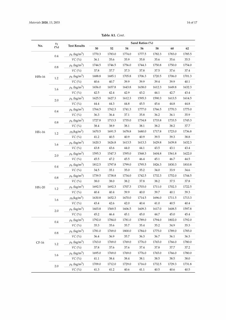
Table A1. Cont.
No.vf
(%) Test ResultsSand Ratios (%)
50 52 54 56 58 60 62
HFb-16
0.4ρb (kg/m3) 1770.3 1783.0 1774.0 1777.5 1782.3 1783.0 1785.5
VC (%) 36.1 35.6 35.9 35.8 35.6 35.6 35.5
0.8ρb (kg/m3) 1744.5 1746.5 1756.0 1744.3 1750.8 1750.0 1754.0
VC (%) 37.8 37.7 37.3 37.8 37.5 37.6 37.4
1.2ρb (kg/m3) 1688.8 1685.1 1705.8 1706.3 1720.5 1706.0 1701.3
VC (%) 40.6 40.7 39.9 39.9 39.4 39.9 40.1
1.6ρb (kg/m3) 1656.0 1657.8 1643.8 1638.0 1612.3 1649.8 1632.3
VC (%) 42.5 42.4 42.9 43.2 44.1 42.7 43.4
2.0ρb (kg/m3) 1625.5 1627.3 1612.3 1595.3 1590.3 1613.5 1614.5
VC (%) 44.4 44.3 44.8 45.5 45.6 44.8 44.8
HFc-16
0.4ρb (kg/m3) 1764.5 1762.3 1741.3 1777.0 1766.5 1770.3 1775.0
VC (%) 36.3 36.4 37.1 35.8 36.2 36.1 35.9
0.8ρb (kg/m3) 1727.8 1713.3 1735.0 1734.8 1733.8 1733.5 1745.3
VC (%) 38.4 38.9 38.1 38.1 38.2 38.2 37.7
1.2ρb(kg/m3) 1670.5 1691.5 1678.8 1680.0 1717.8 1723.0 1736.8
VC (%) 41.2 40.5 40.9 40.9 39.5 39.3 38.8
1.6ρb (kg/m3) 1620.3 1626.8 1613.5 1613.3 1629.8 1639.8 1632.3
VC (%) 43.8 43.6 44.0 44.1 43.5 43.1 43.4
2.0ρb (kg/m3) 1595.3 1547.3 1595.0 1568.3 1604.8 1561.8 1622.0
VC (%) 45.5 47.2 45.5 46.4 45.1 46.7 44.5
HFc-20
0.4ρb (kg/m3) 1812.5 1797.8 1799.0 1795.5 1826.3 1830.3 1810.8
VC (%) 34.5 35.1 35.0 35.2 34.0 33.9 34.6
0.8ρb (kg/m3) 1739.5 1738.8 1734.0 1742.5 1732.3 1752.0 1744.5
VC (%) 38.0 38.0 38.2 37.8 38.2 37.5 37.8
1.2ρb (kg/m3) 1692.5 1692.3 1707.3 1703.0 1711.0 1702.3 1722.5
VC (%) 40.4 40.4 39.9 40.0 39.7 40.1 39.3
1.6ρb(kg/m3) 1630.8 1652.3 1670.0 1714.5 1696.0 1711.5 1713.3
VC (%) 43.4 42.6 42.0 40.4 41.0 40.5 40.4
2.0ρb (kg/m3) 1603.8 1569.5 1606.5 1609.3 1617.0 1608.5 1597.8
VC (%) 45.2 46.4 45.1 45.0 44.7 45.0 45.4
CF-16
0.4ρb (kg/m3) 1792.0 1784.0 1781.0 1789.0 1794.0 1802.0 1792.0
VC (%) 35.3 35.6 35.7 35.4 35.2 34.9 35.3
0.8ρb (kg/m3) 1781.0 1769.0 1800.0 1784.0 1775.0 1789.0 1785.0
VC (%) 36.4 36.9 35.7 36.3 36.7 36.1 36.3
1.2ρb (kg/m3) 1763.0 1769.0 1769.0 1776.0 1765.0 1766.0 1780.0
VC (%) 37.8 37.6 37.6 37.4 37.8 37.7 37.2
1.6ρb (kg/m3) 1695.0 1769.0 1769.0 1776.0 1765.0 1766.0 1780.0
VC (%) 41.1 38.4 38.4 38.1 38.5 38.5 38.0
2.0ρb (kg/m3) 1709.0 1712.0 1729.0 1716.0 1732.5 1729.3 1731.8
VC (%) 41.3 41.2 40.6 41.1 40.5 40.6 40.5
Materials 2020, 13, 2833 15 of 17
References
1. Larrard, F.D. Concrete Mixture Proportioning: A Scientific Approach; Routledge: New York, NY, USA, 1999.2. Ghanem, H.; Ayman, Y.O.; Dandachy, T.M. The impact of steel fibers on the properties of self compacting
concrete. International Congress and Exhibition “Sustainable Civil Infrastructures”: Innovative InfrastructureGeotechnology. In Proceedings of the GeoMEast 2018: Advances and Challenges in Structural Engineering,Cairo, Egypt, 24–28 November 2018; pp. 138–150.
3. Ding, X.X.; Li, C.Y.; Han, B.; Lu, Y.Z.; Zhao, S.B. Effects of different deformed steel-fibers on preparation andfundamental properties of self-compacting SFRC. Constr. Build. Mater. 2018, 168, 471–481. [CrossRef]
4. Ding, X.X.; Li, C.Y.; Li, Y.Z.; Lu, Y.Z.; Song, C.; Zhao, S.B. Experimental and numerical study on stress-strainbehavior of self-compacting SFRC under uniaxial compression. Constr. Build. Mater. 2018, 185, 30–38.[CrossRef]
5. Huang, K.J.; Li, G.F.; Wang, Y.G.; Wei, Y. Properties of high strength self-compacting steel fiber reinforcedconcrete used in bridge steel-mixes union section. J. Wuhan Univ. Technol. 2013, 35, 107–111, 116.
6. Mastali, M.; Dalvand, A. Fresh and hardened properties of self-compacting concrete reinforced with hybridrecycled steel–polypropylene fiber. J. Mater. Civil. 2017, 29, 04017012. [CrossRef]
7. Mastali, M.; Dalvand, A. Use of silica fume and recycled steel fibers in self-compacting concrete (SCC).Constr. Build. Mater. 2016, 30, 196–209. [CrossRef]
8. Wang, C.; Li, H.B.; Yang, C.H.; Ye, J.X.; Bai, G. Preparation technology of fiber toughened self-compactinghigh-strength concrete. J. Civil. Archit. Environ. Eng. 2013, 35, 129–134.
9. Basheerudeen, A.; Anandan, S. Simplified mix design procedures for steel fibre reinforced self-compactingconcrete. Eng. J. 2015, 19, 22–24. [CrossRef]
10. Sahmaran, M.; Yaman, I.O. Hybrid fiber reinforced self-compacting concrete with a high-volume coarse flyash. Constr. Build. Mater. 2007, 21, 150–156. [CrossRef]
11. Athiyamaan, V.; Mohan Ganesh, G. Experimental, statistical and simulation analysis on impact of microsteel—Fibres in reinforced SCC containing admixtures. Constr. Build. Mater. 2020, 246, 118450. [CrossRef]
12. Alberti, M.G.; Enfedaque, A.; Gálvez, J.C.; Cortez, A. Optimisation of fibre reinforcement with a combinationstrategy and through the use of self-compacting concrete. Constr. Build. Mater. 2020, 235, 117289. [CrossRef]
13. Tsai, C.T.; Li, L.S.; Chang, C.C.; Hwang, C.L. Durability design and application of steel fiber reinforcedconcrete in Taiwan. Arab. J. Sci. Eng. 2009, 34, 57–79.
14. Grunewald, S. Performance Based Design of Self-Compacting Steel Fiber Reinforced Concrete. Ph.D. Thesis,Delft University of Technology, Delft, The Netherlands, 2004.
15. Yu, A.B.; Standish, N.; McLean, A. Porosity calculation of binary mixtures of non-spherical particles.J. Am. Ceram. Soc. 1993, 76, 2813–2816. [CrossRef]
16. Ferrara, L.; Park, Y.D.; Shah, S.P. A method for mix-design of fiber-reinforced self-compacting concrete.Cement. Concrete. Res. 2007, 37, 957–971. [CrossRef]
17. Saak, A.W.; Jennings, H.M.; Sha, S.P. New methodology for designing self-compacting concrete. ACI Mater. J.2001, 98, 429–439.
18. Gueciouer, D.; Youcef, G.; Tarek, N. Rheological and mechanical optimization of a steel fiber reinforcedself-compacting concrete using the design of experiments method. Eur. J. Environ. Civ. En. 2019, 11, 1–22.[CrossRef]
19. Fernandes, P.A.L.; Veludo., J.; Almeida, N.; Baptista, J.; Rodrigues, H. Study of a self-compactingfiber-reinforced concrete to be applied in the precast industry. Innov. Infrast. Sol. 2018, 28, 1–11. [CrossRef]
20. Pereira, E.N.B.; Barros, J.A.O.; Camões, A. Steel fiber-reinforced self-compacting concrete: Experimentalresearch and numerical simulation. J. Struct. Eng. 2008, 134, 1310–1321. [CrossRef]
21. Barros, J.; Pereira, E.; Santos, S. Lightweight panels of steel fiber-reinforced self-compacting concrete. J. Mater.Civ. Eng. 2007, 19, 295–304. [CrossRef]
22. He, X.B.; Liu, S.X.; Liu, Y.; Jia, Q.B. A new two-step mix proportion design of micro-steel fiber reinforcedself-compacting concrete. J. Build. Mater. 2020, 1, 56–63.
23. de Oliveira, L.A.P.; Gomes, J.P.C.; Bernardo, L.F.A.; Ramos, M.M.M. Evaluation of dry mortar ratio as mixdesign parameter for steel fibre reinforced self compacting concrete. Constr. Build. Mater. 2013, 40, 642–649.[CrossRef]
Materials 2020, 13, 2833 16 of 17
24. Mahapatra, C.K.; Barai, S.V. Hybrid fiber reinforced self compacting concrete with fly ash and colloidal nanosilica: A systematic study. Constr. Build. Mater. 2018, 160, 828–838. [CrossRef]
25. Ghorbani, S.; Sharifi, S.; Rokhsarpour, H.; Shoja, S.; Gholizadeh, M.; Rahmatabad, M.A.D.; Brito, J.D. Effect ofmagnetized mixing water on the fresh and hardened state properties of steel fibre reinforced self-compactingconcrete. Constr. Build. Mater. 2020, 248, 118660. [CrossRef]
26. BIBM; CEMBUREAU; EFCA; EFNARC; ERMCO. The European Guidelines for Self-Compacting ConcreteSpecification, Production and Use; EFNARC, Association House: Surrey, UK, 2005; p. 18.
27. European Committee for Standardization. Fibres for Concrete. Steel Fibres: Definitions, Specifications &Conformity, BS EN 14889-1-2006; British Standards Institution: London, UK, 2006.
28. European Committee for Standardization. Concrete Part 9 Additional Rules for Self-Compacting Concrete (SCC),BS EN 206-9-2010; British Standards Institution: London, UK, 2010.
29. Ministry of Housing and Urban-Rural Development of the People’s Republic of China. Technical Specificationfor Application of Self-Compacting Concrete, JGJ/T 283-2012; China Architecture & Building Press: Beijing,China, 2012.
30. China Association of Engineering Construction Standardization. Test Methods for Steel Fiber Reinforced Concrete,CECS 13:2009; China Planning Press: Beijing, China, 2010.
31. Ministry of Housing and Urban-Rural Development of the People’s Republic of China. Steel Fiber ReinforcedConcrete, JG/T 472-2015; China Architecture & Building Press: Beijing, China, 2015.
32. Ministry of Housing and Urban-Rural Development of the People’s Republic of China. Technical Specificationfor Application of Fiber Reinforced Concrete, JGJ/T 221-2010; China Building Industry Press: Beijing, China, 2010.
33. Ding, X.X.; Li, C.Y.; Xu, Y.Y.; Li, F.L.; Zhao, S.B. Experimental study on long-term compressive strength ofconcrete with manufactured sand. Constr. Build. Mater. 2016, 108, 67–73. [CrossRef]
34. Zhao, S.B.; Ding, X.X.; Zhao, M.S.; Li, C.Y.; Pei, S.W. Experimental study on tensile strength development ofconcrete with manufactured sand. Constr. Build. Mater. 2017, 138, 247–253. [CrossRef]
35. Zhao, M.L.; Ding, X.X.; Li, J.; Law, D. Numerical analysis of mix proportion of self-compacting concretecompared to ordinary concrete. Key Eng. Mater. 2018, 789, 69–75. [CrossRef]
36. Ding, X.X.; Zhao, M.L.; Zhou, S.Y.; Fu, Y.; Li, C.Y. Statistical analysis and preliminary study on the mixproportion design of self-compacting SFRC. Materials 2019, 12, 637. [CrossRef] [PubMed]
37. Ministry of Housing and Urban-Rural Development of the People’s Republic of China. Standard for TechnicalRequirements and Test Method of Sand and Crushed Stone (or Gravel) for Ordinary Concrete, JGJ 52-2006;China Planning Press: Beijing, China, 2006.
38. Zhao, M.L.; Li, J.; Law, D. Effects of flowability on SFRC fibre distribution and properties. Magaz. Concr. Res.2017, 69, 1043–1054. [CrossRef]
39. American Society of Testing Materials. Standard Test Method for Bulk Density (“Unit Weight”) and Voids inAggregate, ASTM C29/C29M—17a; ASTM International: West Conshohocken, PA, USA, 2017.
40. Vilanova, A.; Fernandez-Gomez, J.; Landsberger, G.A. Evaluation of the mechanical properties of selfcompacting concrete using current estimating models: Estimating the modulus of elasticity, tensile strengthand modulus of rupture of self compacting concrete. Constr. Build. Mater. 2011, 25, 3417–3426. [CrossRef]
41. Ministry of Housing and Urban-Rural Development of the People’s Republic of China. Specification for MixProportion Design of Ordinary Concrete, JGJ 55-2011; China Building Industry Press: Beijing, China, 2011.
42. Standardization Administration of the People’s Republic of China. Common Portland Cement, GB175-2007;China Building Industry Press: Beijing, China, 2007.
43. Ministry of Housing and Urban-Rural Development of the People’s Republic of China. Technical Code forApplication of Mineral Admixture, GB/T51003-2014; China Building Industry Press: Beijing, China, 2014.
44. Ministry of Housing and Urban-Rural Development of the People’s Republic of China. Standard for TestMethod of Performance on Ordinary Fresh Concrete, GB/T 50080-2016; China Building Industry Press: Beijing,China, 2016.
45. American Society of Testing Materials. Standard Test Method for Air Content of Freshly Mixed Concrete by thePressure Method, ASTM C231 C231M-2017a; ASTM International: West Conshohocken, PA, USA, 2017.
46. Ding, Y.N.; Yang, N. Experimental study on fiber reinforced high performance concrete. J. ShengyangJianzhu Univ. 2006, 22, 125–128.
47. Miao, B.Q.; Chern, J.C.; Yang, C.A. Influences of fiber content on properties of self-compacting steel fiberreinforced concrete. J. Chin. Inst. Eng. 2003, 26, 523–530. [CrossRef]
Materials 2020, 13, 2833 17 of 17
48. American Society of Testing Materials. Standard Test Method for Slump Flow of Self-Consolidating Concrete,ASTM C1611-C1611M-2014; ASTM International: West Conshohocken, PA, USA, 2014.
49. American Society of Testing Materials. Standard Test Method for Passing Ability of Self-Consolidating Concrete byJ-Ring, ASTM C1621_C1621M-2014; ASTM International: West Conshohocken, PA, USA, 2014.
50. Ministry of Housing and Urban-Rural Development of the People’s Republic of China. Standard for TestMethods for Concrete Physical and Mechanical Properties, GB/T 50081-2019; China Building Industry Press:Beijing, China, 2019.
51. European Committee for Standardization. Testing hardened Concrete-Part 3: Compressive Strength of TestSpecimens, BS EN 12390-3-2009; European Committee for Standardization: London, UK, 2009.
52. European Committee for Standardization. Testing Hardened Concrete-Part 6: Tensile Splitting Strength of TestSpecimen, BS EN 12390-6-2009; European Committee for Standardization: London, UK, 2009.
© 2020 by the authors. Licensee MDPI, Basel, Switzerland. This article is an open accessarticle distributed under the terms and conditions of the Creative Commons Attribution(CC BY) license (http://creativecommons.org/licenses/by/4.0/).
Related Documents