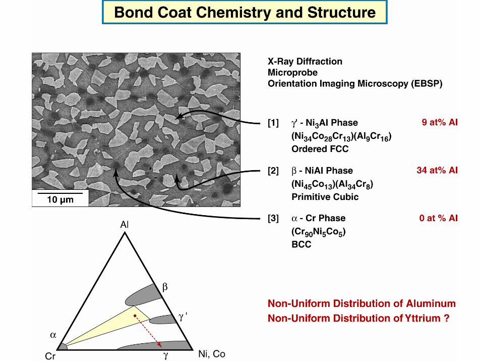
Materials and Structures for Aerospace Propulsion Systems

Welcome message from author
This document is posted to help you gain knowledge. Please leave a comment to let me know what you think about it! Share it to your friends and learn new things together.
Transcript
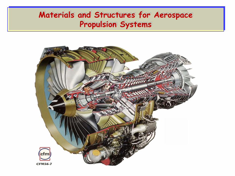
Materials and Structures for AerospacePropulsion Systems
Materials and Structures for AerospacePropulsion Systems

X-43b
Image courtesy of ATK
Scramjets Rocket
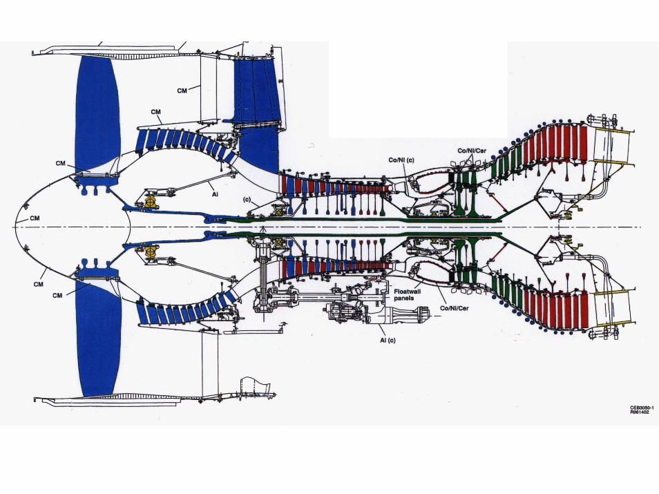
Aeroturbine

High By-pass Aeroturbine
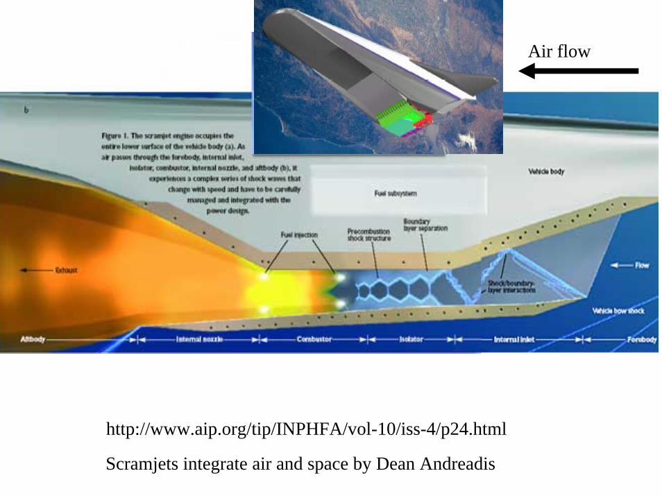
http://www.aip.org/tip/INPHFA/vol-10/iss-4/p24.html
Air flow
Scramjets integrate air and space by Dean Andreadis

Efficiency of Various Propulsion Cycles:Specific Impulse (Thrust/weight)
Turbojets
Scramjets
Ramjets
TurbojetsRamjets
Scramjets
Hydrocarbon Fuels
Hydrogen Fuel
0
2000
4000
6000
8000
0 10 20
MACH NUMBER
Isp
RocketRBCCTBCC
Rockets

0
1
2
3
4
5
6
7
8
9
10
0 1 2 3 4 5 6 7 8 9 10 11 12
Flight Mach Number
TSFC
(Lbm
/Lbf
/Hr.)
Ramjet Take Over
Scram/Rocket
Ram/Scram Operation
Rocket Off
Conventional RocketTu
rbin
e En
gine
s
Hydrogen Fuel
Specific Fuel Consumption for Various Concepts

Fuel Efficiency In the Aero-turbine Industry:
PW4098PW4084
JT8D-217
JT8D-9
JT3D-1
JT9D-7R4G2
JT9D-3A
JT9D-7A
PW4056PW2037
V2500 A1
PW4168
CJ805
CF6-6DCFM56-2
CFM56-5A
GE90-85B
CF6-80ACFM56-5C4
CF6-80C2-B6F
CF6-80E1-A2
RB-211-535E4
TRENT 895
RB-211-524D
TAY 620
BR 715
1950 1960 1970 1980 1990 2000 2010 2020
Certification Date
Spec
ific
Fuel
co
nsum
ptio
n
JT3C
Low Bypass Turbofan
2nd Gen High Bypass Turbofan
High Bypass Turbofan
Turbojet
GE90-115B
R. SHAFRICK, GE Aircraft Engines

62 64 66 68 70 72 74 76 78 80 82 84 86 88 90 92 94 96 98 00 02 04 06 08 10 12
Engine Certification Date
Gas
Tem
pera
ture
, FR
T
CF6-50E CF6-50E2
CF6-80A3
CFM56-2B
CF6-80C2A5CF6-80E1
CFM56-3B1
CFM56-3C
CFM56-5A
CFM56-5BCFM56-5C4
CFM56-5C2CFM56-7B
CF34-8C1
CF34-10
GE90-115B
GE90-94B
GE90-90B
CF6-80C2D1F
CF6-80C2B1F
CF6-80C2A1CFM56-3B2
CF34-3BCF34-3A
Trent 556
PW 6024
Trent 892
PW 4090
BR 715
BR 710
V2533Trent 772
PW 4062
JT8D-219
PW 2037
JT9D
RB 211
TF33
Engine Temperature Trend

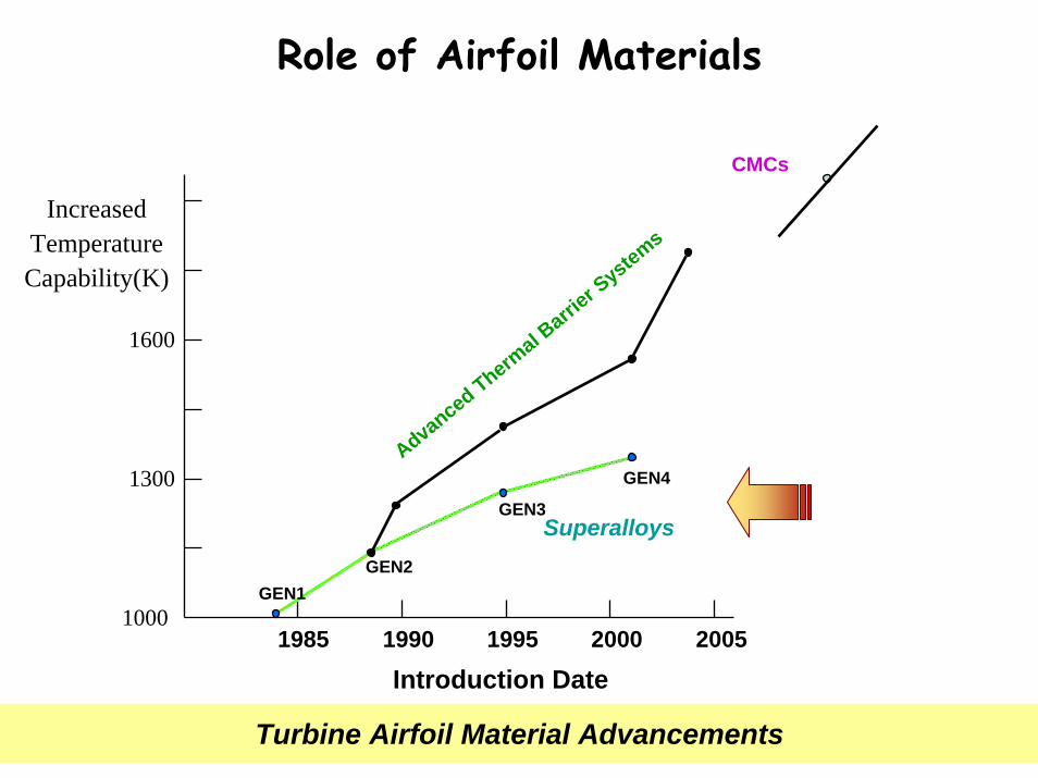
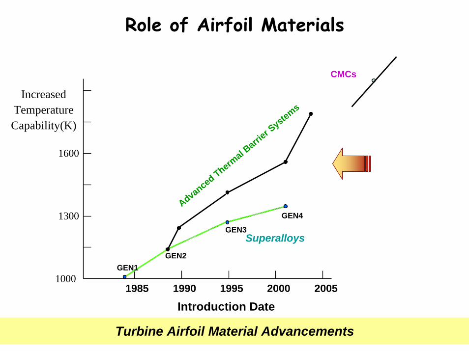
Role of Airfoil Materials
IncreasedTemperature Capability(K)
1985 1990 1995 2000 2005
Introduction Date
GEN1GEN2
GEN3
GEN4
CMCs
Advanced Thermal B
arrier S
ystems
Turbine Airfoil Material Advancements
Superalloys
1000
1300
1600

Specific Strengths of Metallic Systems
Superalloys &Refractories

More High Temperature Materials

Role of Airfoil Materials
IncreasedTemperature Capability(K)
1985 1990 1995 2000 2005
Introduction Date
GEN1GEN2
GEN3
GEN4
CMCs
Advanced Thermal B
arrier S
ystems
Turbine Airfoil Material Advancements
Superalloys
1000
1300
1600

Superalloy Turbine Air Foils
Equiaxed (EQ) Dir. Sol. (DS) Single Xtal (SX)

ASM-TMS NY042198 16
Year of Introduction
840
860
880
900
920
940
960
980
1000
1020
1969 1972 1982 1984 1988 1989 1994
Ρ80
Ρ125
Ρ80Η
Ρ142
Ν4
Ν5
Ν6
Tem
pera
ture
Cap
abili
ty -
°C
ΜΞ
4
2000
Ni Superalloy Improvements
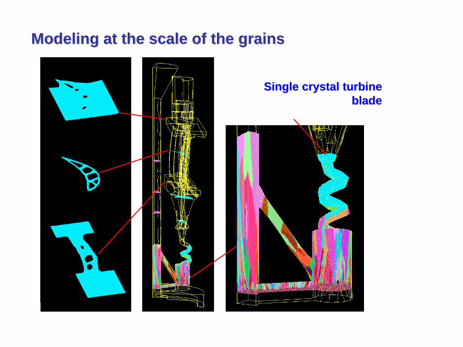
ModelingModeling at the scale of the grainsat the scale of the grains
Single crystal turbine Single crystal turbine bladeblade
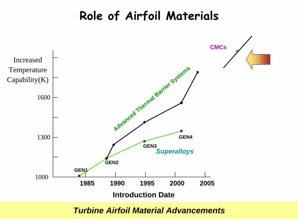
Role of Airfoil Materials
IncreasedTemperature Capability(K)
1985 1990 1995 2000 2005
Introduction Date
GEN1GEN2
GEN3
GEN4
CMCs
Advanced Thermal B
arrier S
ystems
Turbine Airfoil Material Advancements
Superalloys
1000
1300
1600

Airfoil TechnologyAirfoil TechnologyHeatTransfer
High Performance Coating Systems:Enabling technology for advanced gas turbines

Transverse Section

Al Reservoir
Thermal Barrier Multilayer

Nanoscale Porosity

Deposition Effects on MicrostructureDeposition Effects on Microstructure
Platform Mode
Airfoil Mode
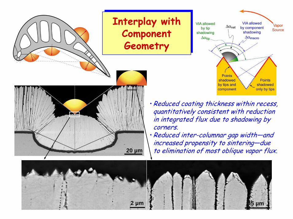
• Reduced coating thickness within recess, quantitatively consistent with reduction in integrated flux due to shadowing by corners.
• Reduced inter-columnar gap width—and increased propensity to sintering—due to elimination of most oblique vapor flux.20 µm
5 µm2 µm
Interplay withComponentGeometry
Interplay withComponentGeometry
Role of Airfoil Materials
IncreasedTemperature Capability(K)
1985 1990 1995 2000 2005
Introduction Date
GEN1GEN2
GEN3
GEN4
CMCs
Advanced Thermal B
arrier S
ystems
Turbine Airfoil Material Advancements
Superalloys
1000
1300
1600
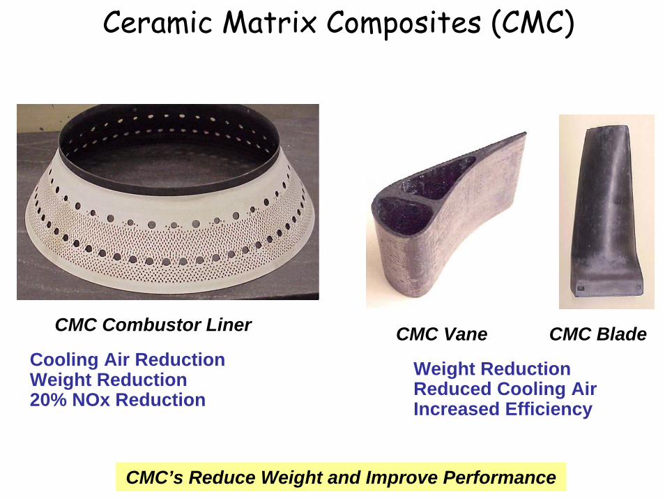
Ceramic Matrix Composites (CMC)
CMC’s Reduce Weight and Improve Performance
CMC Combustor Liner
Cooling Air Reduction Weight Reduction20% NOx Reduction
CMC Vane CMC Blade
Weight ReductionReduced Cooling AirIncreased Efficiency

(MI) SiC/SiC (DENSE MATRIX)
T = 1400C (Metals < 1100C)
High Thermal Conductivity
Inter-laminar Shear Strength
Reduced Sensitivity to Pesting
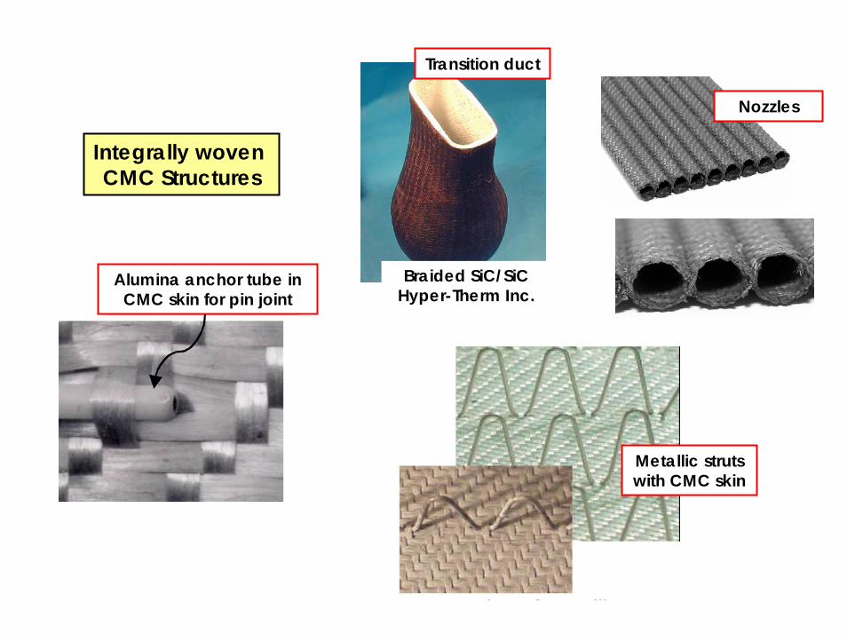
Integrally woven CMC Structures
Transition duct
Braided SiC/SiCHyper-Therm Inc.
Alumina anchor tube in CMC skin for pin joint
Metallic struts with CMC skin
Nozzles

±45°
Angle Interlock Sylramic/SiC

CMC Inner Combustor Liner After Engine Testing
Hi-Nicalon, Slurry Cast Successful Engine TestingPre and Post Engine Test NDE
Revealed DegradationAdditional Engine Testing
CMC Combustor Liner Rig & Engine Testing Successful
CMC Combustor Liners
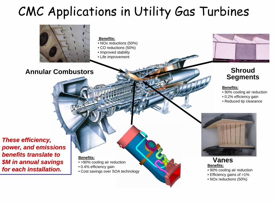
CMC Applications in Utility Gas Turbines
Vanes
Annular Combustors ShroudSegments
Benefits:• NOx reductions (50%)• CO reductions (50%)• Improved stability• Life improvement
Benefits:• 90% cooling air reduction• Efficiency gains of >1%• NOx reductions (50%)
Benefits:• >90% cooling air reduction• 0.4% efficiency gain• Cost savings over SOA technology
Benefits:• 90% cooling air reduction• 0.2% efficiency gain• Reduced tip clearance
These efficiency, power, and emissions benefits translate to $M in annual savings for each installation.
These efficiency, These efficiency, power, and emissions power, and emissions benefits translate to benefits translate to $M in annual savings $M in annual savings for each installation.for each installation.

Hybrid CMC Concept
The "hybrid" concept involves use of a moderate temperature (~1100° -1200°C) CMC structural member bonded to a ceramic insulating materialhaving good stability at 1600°C and good erosion resistance.
• Oxide fiber available• Insulating material technology available• Reduces cooling needs drastically
CeramicAdhesiveBond Line
Temp.1100°C Structural CMC ~4mm
~3mm
Hot Face Temp1600°C
Cold Face Temp750°C
FGI Insulation LayerFGI Insulation Layer

Role of Airfoil Materials
IncreasedTemperature Capability(K)
1985 1990 1995 2000 2005
Introduction Date
GEN1GEN2
GEN3
GEN4
SiC/SiC CMCs
Advanced Thermal B
arrier S
ystems
Turbine Airfoil Material Advancements
Superalloys
1000
1300
1600

Thermal Barrier Multilayer:Challenging Thermo-Chemo-Mechanical System

Thermal Property Interplay

RESIDUAL STRESS IN TGORESIDUAL STRESS IN TGO
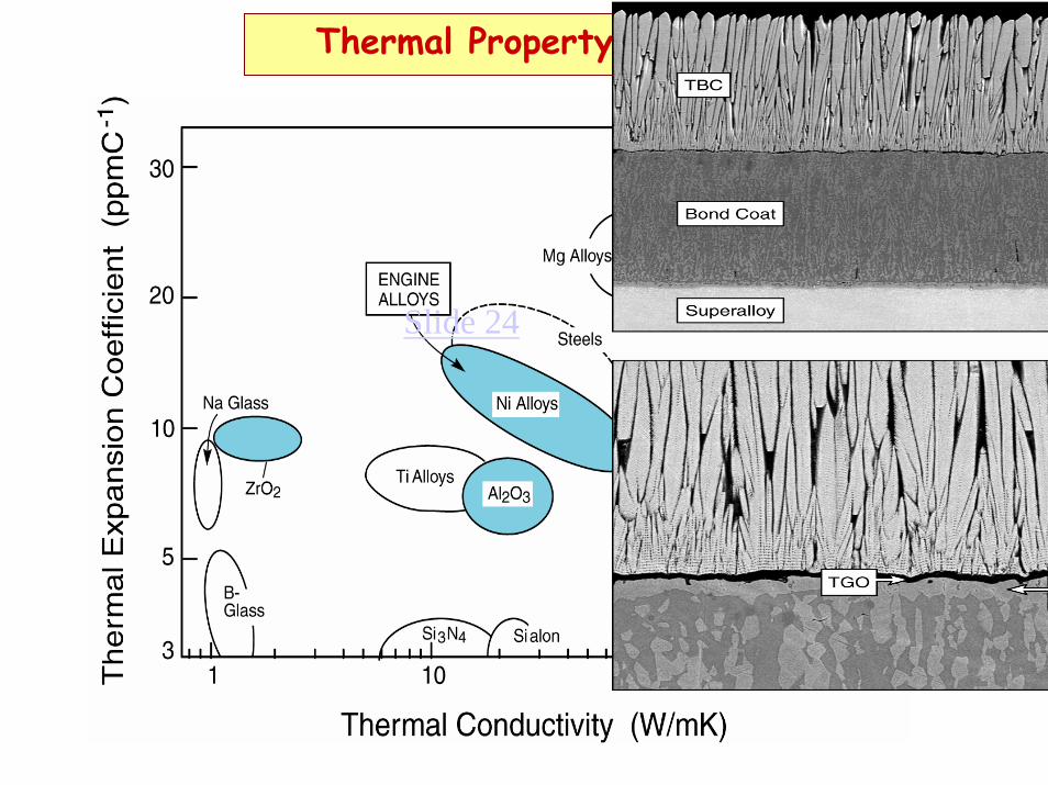
Thermal Property Interplay
Slide 24

Thermal Barrier Multilayer:Challenging Thermo-Chemo-Mechanical System

As Deposited
TGO
EB-PVD on FeCrAlY substrate
TGO
After 100h at 1200°C
YSZ Compatibility with TGOYSZ Compatibility with TGO
1200°C
Limit of thermochemicalcompatibility ~21%YO1.5
Zirconatereactive with TGO
1 µm
7YSZ compatible with TGO(no inter-phases formed)

Degradation Modes In Engines
40%
80%
TBC
spal
latio
n
ImpactDamage
1820 engine cycles
TBCspallation
Delay Spalling By UnderstandingMechanisms
And Adjusting ConstituentProperties

Step I:Identify All Mechanisms Limiting DurabilityStep I:Identify All Mechanisms Limiting Durability
Step II: Develop Models that Relate Durability to Material Properties
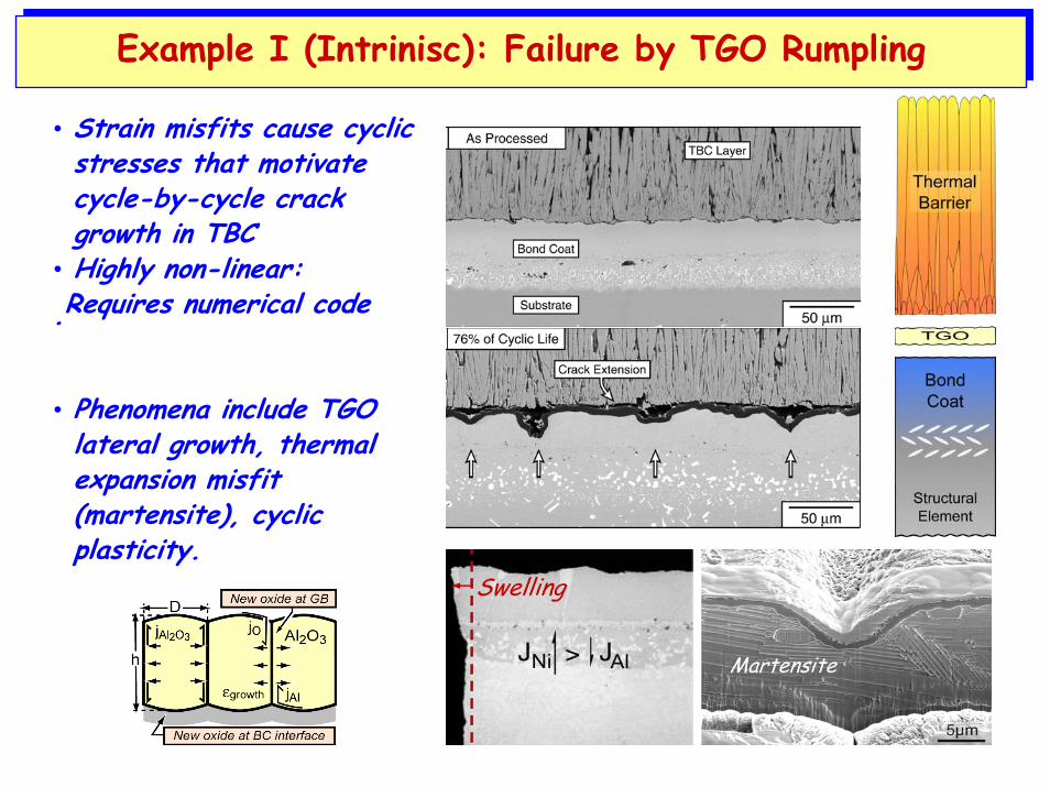
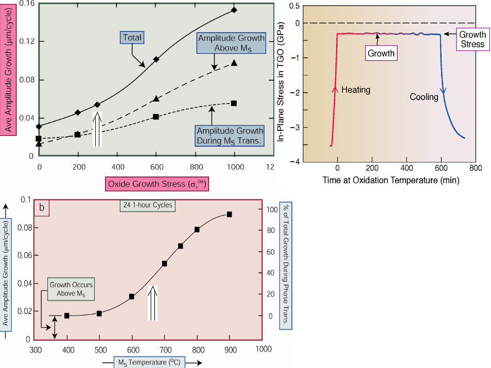
• Strain misfits cause cyclic stresses that motivate cycle-by-cycle crack growth in TBC
• Highly non-linear:Requires numerical code.
Example I (Intrinisc): Failure by TGO RumplingExample I (Intrinisc): Failure by TGO Rumpling
• Phenomena include TGO lateral growth, thermal expansion misfit (martensite), cyclic plasticity.
Martensite
Swelling

LARGE SCALE BUCKLE: THE END OF LIFELARGE SCALE BUCKLE: THE END OF LIFE••WHAT HAPPENED EARLIERWHAT HAPPENED EARLIER??
Fails at Oxide/Oxide Interface
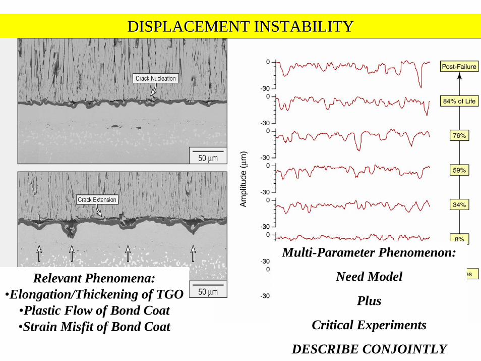
DISPLACEMENT INSTABILITYDISPLACEMENT INSTABILITY
Relevant Phenomena:•Elongation/Thickening of TGO
•Plastic Flow of Bond Coat•Strain Misfit of Bond Coat
Multi-Parameter Phenomenon:
Need Model
Plus
Critical Experiments
DESCRIBE CONJOINTLY

OBJECTIVE: DEVISE MECHANISM MAPS THAT SPECIFY SALIENT NON-DIMENSIONAL PARAMETERS

UNDERSTAND THE FUNDAMENTALS
TGO
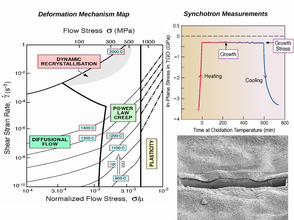
Deformation Mechanism Map Synchotron Measurements
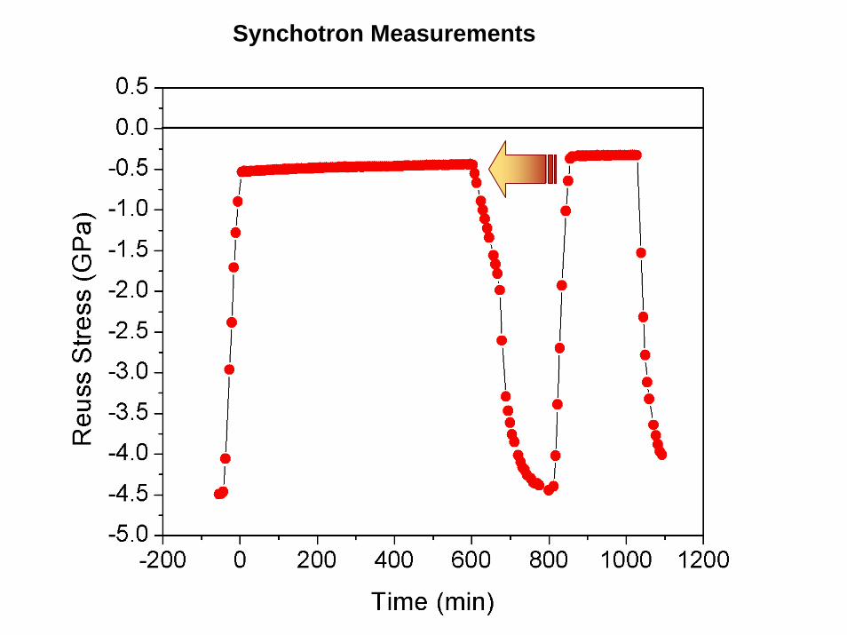
Synchotron Measurements

•Thermal Expansion•Martensite•Swelling
“Soften” Bond Coat
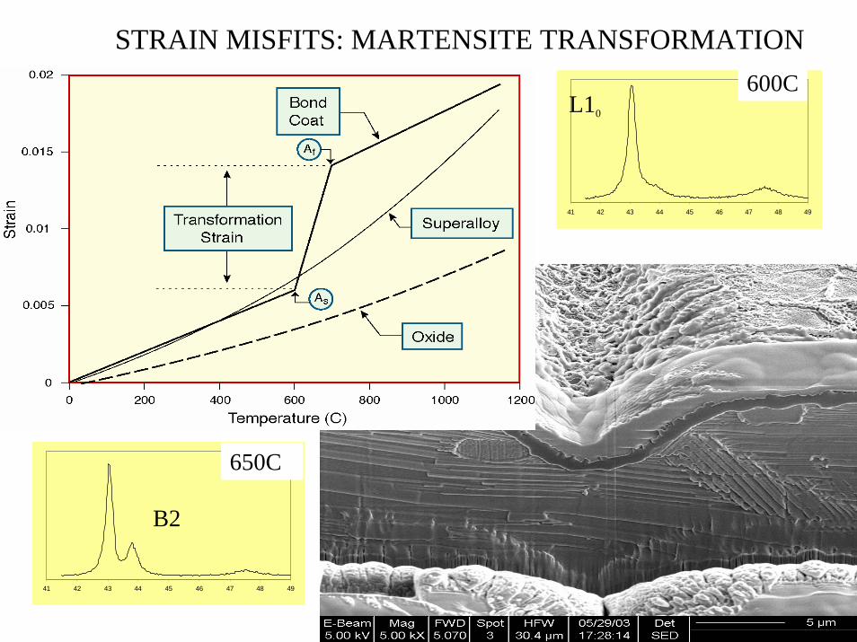
STRAIN MISFITS: MARTENSITE TRANSFORMATION
41 42 43 44 45 46 47 48 49
41 42 43 44 45 46 47 48 49
600C
650C
L10
B2

Model Validation: Example
1. Elastic properties of constituents
2. Thermal expansion mismatch between layers.
3. Power-law creep.
4. Reversible phase transformation in bond coat.
5. Growth stress in TGO.
6. Thickening and lateral growth strain in the TGO
7. Initial Interface Imperfections
VALIDATION EXPERIMENTS: AN EXAMPLE

QuickTime™ and aGIF decompressor
are needed to see this picture.
ANIMATION OF TGO DISTORTION AND ELONGATION

BC
Substrate
Code now in use at GE
Balint-Hutchinson CodeModel
Validation:Transition
to GE
Model Validation:Transition
to GE
TGO

SENSITIVITY STUDY USING MECHANISM MAP:CAN MECHANISM BE SUPPRESSED?
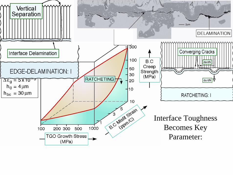
USE MECHANISM MAP TO ELIMINATE RATCHETING
Interface ToughnessBecomes Key
Parameter:
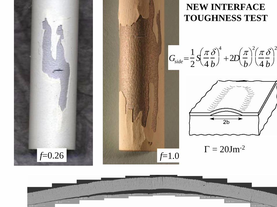
Gside =12
Sπ4
δb
⎛ ⎝
⎞ ⎠
4
+2Dπb
⎛ ⎝
⎞ ⎠
2 π4
δb
⎛ ⎝
⎞ ⎠
2
f=0.26 f=1.0
NEW INTERFACE TOUGHNESS TEST
Γ = 20Jm-2
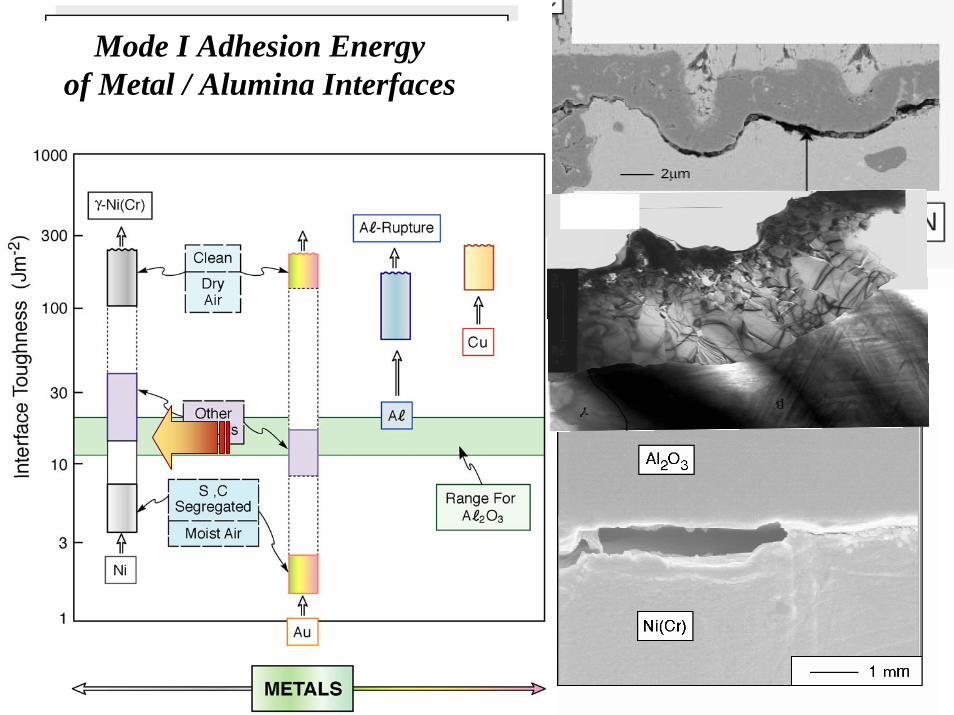
Mode I Adhesion Energy of Metal / Alumina Interfaces
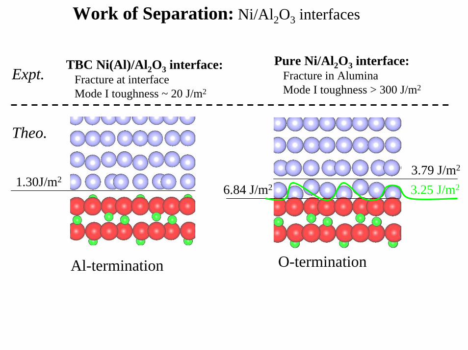
Work of Separation: Ni/Al2O3 interfaces
1.30J/m2
Al-termination O-termination
3.79 J/m2
6.84 J/m2 3.25 J/m2
TBC Ni(Al)/Al2O3 interface:Fracture at interfaceMode I toughness ~ 20 J/m2
Pure Ni/Al2O3 interface:Fracture in AluminaMode I toughness > 300 J/m2
Expt.
Theo.

Failure Modes After Engine TestDelay Spalling
By UnderstandingMechanisms
AndAdjusting Constituent
Properties
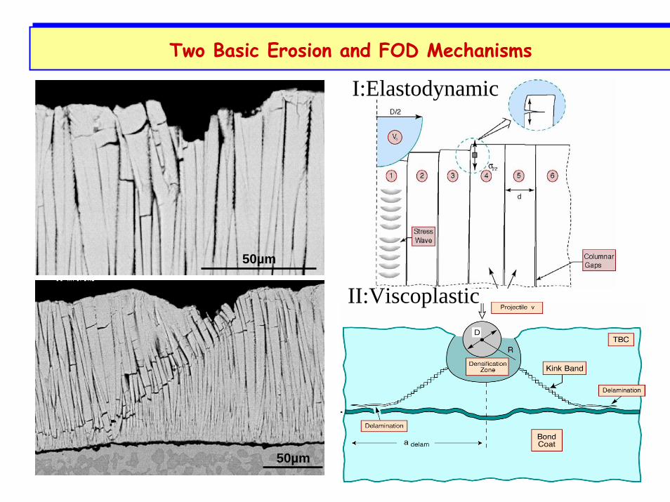
50µm
50µm
Two Basic Erosion and FOD MechanismsTwo Basic Erosion and FOD Mechanisms
I:Elastodynamic
II:Viscoplastic

4
LESimulations
Viscoplastic Domain
QuickTime™ and aBMP decompressor
are needed to see this picture.
Soft at High Temperature

ELASTO-DYNAMICDOMAIN
Identify Importance of Material Properties:
High ToughnessSoft at High Temperature
Erosion Threshold MapErosion Threshold Map
Related Documents