MASTERYS BC 100-120 kVA 安装及操作手册 CN Installations- und bedienungsanleitung DE Manual de instalación y uso ES Asennus- ja käyttöohje FI Manuel d’installation et d’utilisation FR Installation and operating manual GB Manuale di installazione e uso IT Installatie– en bedieningshandleiding NL Dokumentacja Techniczno-Ruchowa PL Manual de instalação e funcionamento PT Manual de instalare şi utilizare RO Руководство по установке и эксплуатации RU Navodila za priključitev in uporabo SI Kurulum ve kullanım kılavuzu TR

Welcome message from author
This document is posted to help you gain knowledge. Please leave a comment to let me know what you think about it! Share it to your friends and learn new things together.
Transcript

MASTERYS BC1 0 0 - 1 2 0 k V A
安装及操作手册 CN
Installations- und bedienungsanleitung DE
Manual de instalación y uso ES
Asennus- ja käyttöohje FI
Manuel d’installation et d’utilisation FR
Installation and operating manual GB
Manuale di installazione e uso IT
Installatie– en bedieningshandleiding NL
Dokumentacja Techniczno-Ruchowa PL
Manual de instalação e funcionamento PT
Manual de instalare şi utilizare RO
Руководство по установке и эксплуатации RU
Navodila za priključitev in uporabo SI
Kurulum ve kullanım kılavuzu TR

2 MASTERYS BC 100-120 kVA - Ref.: IOMMASBCXX07-GB 03
This SOCOMEC continuous power system is guaranteed against any manufacturing or material defects.
The warranty is valid for 12 (twelve) months from the commission date, provided activation is carried out by SOCOMEC person-nel or personnel from a support centre authorised by SOCOMEC, and no more than 15 (fifteen) months from being shipped from SOCOMEC.
The warranty is valid throughout national territory. If the UPS is exported abroad, the warranty will only cover the parts used to repair faults.
The warranty is valid ex-works and covers labour and parts used to repair the faults.
The warranty shall not apply in the following cases:
• Failure due to unforeseen circumstances or force majeure (lightning, floods, etc.);
• Failure due to negligence or improper use (use outside limits: temperature, humidity, ventilation, electric power supply, applied load, batteries);
• Insufficient or inappropriate maintenance;
• When maintenance, repairs or modifications have not been carried out by SOCOMEC personnel, or personnel from a support centre authorised by SOCOMEC.
• If the battery has not been recharged in accordance with the terms indicated on the packaging and in the manual, in the event of long periods of storage or UPS inactivity.
SOCOMEC may, at its own discretion, opt for the repair of the product or the replacement of faulty or defective parts with new parts, or with used parts of equivalent quality to new parts with regard to function and performance.
Defective or faulty parts replaced free of charge must be made available to SOCOMEC, which becomes the sole owner.
Replacement or repair of parts, or any modifications to the product during the warranty period, will not extend the duration of the warranty.
SOCOMEC will not be responsible for damages under any circumstances (including, without limitations, damage for loss of earnings, interruption of activity, loss of information or other financial losses) arising from the use of the product.
These conditions are subject to Italian law. Any disputes fall under the jurisdiction of the Court of Vicenza.
CERTIFICATE AND CONDITIONS OF WARRANTY
SOCOMEC retains the full and exclusive ownership rights to this document. Only a personal entitlement to use the document for the application indicated by SOCOMEC is granted to the recipient of this document. The reproduction, modification, distribution of this document, either partially or wholly and in any manner, is strictly prohibited except upon Socomec’s express prior written consent.
This document is not a specification. SOCOMEC reserves the right to make any changes to the information provided without prior notice.

3
EN
GL
ISH
MASTERYS BC 100-120 kVA - Ref.: IOMMASBCXX07-GB 03
SUMMARY
EN
GL
ISH
1. SAFETY STANDARDS . . . . . . . . . . . . . . . . . . . . . . . . . . . . . . . . . . . . . . . . . . . . . . . . . . . . . . . . . . . . . . . 41.1. IMPORTANT. . . . . . . . . . . . . . . . . . . . . . . . . . . . . . . . . . . . . . . . . . . . . . . . . . . . . . . . . . . 41.2. DESCRIPTION OF SYMBOLS ON LABELS ATTACHED TO THE UNIT . . . . . . . . . . . . . . 5
2. UNPACKING AND INSTALLATION OF THE UNIT . . . . . . . . . . . . . . . . . . . . . . . . . . . . . . . . . . . . . . . . . . . 62.1. SHIPPING AND MOVING . . . . . . . . . . . . . . . . . . . . . . . . . . . . . . . . . . . . . . . . . . . . . . . . . 62.2. UNPACKING PROCEDURE . . . . . . . . . . . . . . . . . . . . . . . . . . . . . . . . . . . . . . . . . . . . . . . 72.3. MOVING FROM ABOVE . . . . . . . . . . . . . . . . . . . . . . . . . . . . . . . . . . . . . . . . . . . . . . . . . . 82.4. ENVIRONMENTAL REQUIREMENTS . . . . . . . . . . . . . . . . . . . . . . . . . . . . . . . . . . . . . . . 102.5. GENERAL RULES FOR CABLE INSTALLATION ON TRAYS . . . . . . . . . . . . . . . . . . . . . . 122.6. ELECTRICAL REQUIREMENTS . . . . . . . . . . . . . . . . . . . . . . . . . . . . . . . . . . . . . . . . . . . 132.7. INSTALLATION PROCEDURES AND INSTRUCTIONS . . . . . . . . . . . . . . . . . . . . . . . . . . 152.8. GENERATOR CONNECTION . . . . . . . . . . . . . . . . . . . . . . . . . . . . . . . . . . . . . . . . . . . . . 202.9. EXTERNAL ESD CONNECTION . . . . . . . . . . . . . . . . . . . . . . . . . . . . . . . . . . . . . . . . . . . 202.10. ISOLATION TRANSFORMER . . . . . . . . . . . . . . . . . . . . . . . . . . . . . . . . . . . . . . . . . . . . . 202.11. UPS PARALLEL CONFIGURATION . . . . . . . . . . . . . . . . . . . . . . . . . . . . . . . . . . . . . . . . 212.12. SPECIAL PARALLEL CONFIGURATION FEATURES. . . . . . . . . . . . . . . . . . . . . . . . . . . . 24
3. MODES OF OPERATION . . . . . . . . . . . . . . . . . . . . . . . . . . . . . . . . . . . . . . . . . . . . . . . . . . . . . . . . . . . . 253.1. ONLINE OPERATION . . . . . . . . . . . . . . . . . . . . . . . . . . . . . . . . . . . . . . . . . . . . . . . . . . . 253.2. OPERATION IN HIGH EFFICIENCY MODE . . . . . . . . . . . . . . . . . . . . . . . . . . . . . . . . . . . 253.3. OPERATION IN CONVERTER MODE . . . . . . . . . . . . . . . . . . . . . . . . . . . . . . . . . . . . . . . 263.4. OPERATION WITH EXTERNAL MANUAL BYPASS (OPTIONAL) . . . . . . . . . . . . . . . . . . 263.5. OPERATION WITH INTERNAL MAINTENANCE BYPASS . . . . . . . . . . . . . . . . . . . . . . . . 263.6. OPERATION WITH MOTOR GENERATOR (GENSET) . . . . . . . . . . . . . . . . . . . . . . . . . . . 26
4. ACCESS TO CONTROLS . . . . . . . . . . . . . . . . . . . . . . . . . . . . . . . . . . . . . . . . . . . . . . . . . . . . . . . . . . . . 274.1. IDENTIFYING SWITCHING AND CONNECTION POINTS . . . . . . . . . . . . . . . . . . . . . . . . 27
5. HUMAN MACHINE INTERFACE . . . . . . . . . . . . . . . . . . . . . . . . . . . . . . . . . . . . . . . . . . . . . . . . . . . . . . . 285.1. INTRODUCTION . . . . . . . . . . . . . . . . . . . . . . . . . . . . . . . . . . . . . . . . . . . . . . . . . . . . . . 285.2. MIMIC PANEL OVERVIEW . . . . . . . . . . . . . . . . . . . . . . . . . . . . . . . . . . . . . . . . . . . . . . . 295.3. MENU NAVIGATION . . . . . . . . . . . . . . . . . . . . . . . . . . . . . . . . . . . . . . . . . . . . . . . . . . . . 32
6. OPERATING PROCEDURES . . . . . . . . . . . . . . . . . . . . . . . . . . . . . . . . . . . . . . . . . . . . . . . . . . . . . . . . . 386.1. SWITCHING ON. . . . . . . . . . . . . . . . . . . . . . . . . . . . . . . . . . . . . . . . . . . . . . . . . . . . . . . 386.2. SWITCHING ONTO MAINTENANCE BYPASS . . . . . . . . . . . . . . . . . . . . . . . . . . . . . . . . 396.3. SWITCHING ON FROM MAINTENANCE BYPASS . . . . . . . . . . . . . . . . . . . . . . . . . . . . . 396.4. EXTENDED OUT OF SERVICE . . . . . . . . . . . . . . . . . . . . . . . . . . . . . . . . . . . . . . . . . . . . 396.5. EMERGENCY SHUTDOWN . . . . . . . . . . . . . . . . . . . . . . . . . . . . . . . . . . . . . . . . . . . . . . 396.6. UPS GENERAL POWER OFF . . . . . . . . . . . . . . . . . . . . . . . . . . . . . . . . . . . . . . . . . . . . . 39
7. CONNECTIVITY AND COMMUNICATION OPTIONS . . . . . . . . . . . . . . . . . . . . . . . . . . . . . . . . . . . . . . . 407.1. MULTILEVEL COMMUNICATION . . . . . . . . . . . . . . . . . . . . . . . . . . . . . . . . . . . . . . . . . . 407.2. ADC CARD . . . . . . . . . . . . . . . . . . . . . . . . . . . . . . . . . . . . . . . . . . . . . . . . . . . . . . . . . . 417.3. ADC CARD WITH TEMPERATURE SENSOR . . . . . . . . . . . . . . . . . . . . . . . . . . . . . . . . . 427.4. REMOTE MIMIC PANEL . . . . . . . . . . . . . . . . . . . . . . . . . . . . . . . . . . . . . . . . . . . . . . . . . 427.5. NET VISION LAN/WEB INTERFACE . . . . . . . . . . . . . . . . . . . . . . . . . . . . . . . . . . . . . . . . 427.6. PROFIBUS INTERFACE . . . . . . . . . . . . . . . . . . . . . . . . . . . . . . . . . . . . . . . . . . . . . . . . . 427.7. MODBUS-TCP INTERFACE . . . . . . . . . . . . . . . . . . . . . . . . . . . . . . . . . . . . . . . . . . . . . . 437.8. ISOLATED SERIAL PORT RS232 (DB9 CONNECTION) AND RS485 CARD . . . . . . . . . 437.9. SOFTWARE OPTIONS . . . . . . . . . . . . . . . . . . . . . . . . . . . . . . . . . . . . . . . . . . . . . . . . . . 43
8. TROUBLESHOOTING . . . . . . . . . . . . . . . . . . . . . . . . . . . . . . . . . . . . . . . . . . . . . . . . . . . . . . . . . . . . . . 448.1. SYSTEM ALARMS . . . . . . . . . . . . . . . . . . . . . . . . . . . . . . . . . . . . . . . . . . . . . . . . . . . . . 448.2. UPS ALARMS . . . . . . . . . . . . . . . . . . . . . . . . . . . . . . . . . . . . . . . . . . . . . . . . . . . . . . . . 458.3. PREVENTIVE MAINTENANCE . . . . . . . . . . . . . . . . . . . . . . . . . . . . . . . . . . . . . . . . . . . . 45
9. ELECTRICAL OPTIONS . . . . . . . . . . . . . . . . . . . . . . . . . . . . . . . . . . . . . . . . . . . . . . . . . . . . . . . . . . . . . 479.1. INSULATION CONTROLLER . . . . . . . . . . . . . . . . . . . . . . . . . . . . . . . . . . . . . . . . . . . . . 479.2. EXTERNAL MAINTENANCE BYPASS . . . . . . . . . . . . . . . . . . . . . . . . . . . . . . . . . . . . . . 479.3. ACS PCB . . . . . . . . . . . . . . . . . . . . . . . . . . . . . . . . . . . . . . . . . . . . . . . . . . . . . . . . . . . . 47
10. TECHNICAL SPECIFICATIONS . . . . . . . . . . . . . . . . . . . . . . . . . . . . . . . . . . . . . . . . . . . . . . . . . . . . . . 48
4 MASTERYS BC 100-120 kVA - Ref.: IOMMASBCXX07-GB 03
1.1. IMPORTANT
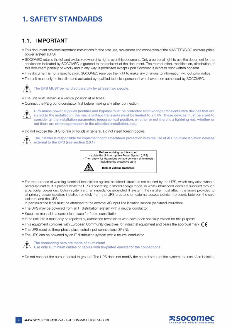
• This document provides important instructions for the safe use, movement and connection of the MASTERYS BC uninterruptible power system (UPS).
• SOCOMEC retains the full and exclusive ownership rights over this document. Only a personal right to use the document for the application indicated by SOCOMEC is granted to the recipient of the document. The reproduction, modifi cation, distribution of this document partially or wholly and in any way is prohibited except upon Socomec’s express prior written consent.
• This document is not a specifi cation. SOCOMEC reserves the right to make any changes to information without prior notice.
• The unit must only be installed and activated by qualifi ed technical personnel who have been authorised by SOCOMEC.
The UPS MUST be handled carefully by at least two people.
• The unit must remain in a vertical position at all times.
• Connect the PE ground conductor fi rst before making any other connection.
UPS mains power supplies (rectifier and bypass) must be protected from voltage transients with devices that are suited to the installation; the mains voltage transients must be limited to 2.5 kV. These devices must be sized to consider all the installation parameters (geographical position, whether or not there is a lightning rod, whether or not there are other suppressors in the electrical installation, etc.).
• Do not expose the UPS to rain or liquids in general. Do not insert foreign bodies.
The installer is responsible for implementing the backfeed protection with the use of AC input line isolation devices external to the UPS (see section 2.6.1).
Before working on this circuit- Isolate the Uninterruptible Power System (UPS)
- Then check for Hazardous Voltage between all terminalsincluding the protective earth
Risk of Voltage Backfeed
• For the purpose of warning electrical technicians against backfeed situations not caused by the UPS, which may arise when a particular load fault is present while the UPS is operating in stored energy mode, or while unbalanced loads are supplied through a particular power distribution system e.g. an impedance grounded IT system, the installer must attach the labels provided to all primary power isolators installed remotely from the UPS area and on external access points, if present, between the said isolators and the UPS. In particular the label must be attached to the external AC input line isolation service (backfeed insulation).
• The UPS may be powered from an IT distribution system with a neutral conductor.
• Keep this manual in a convenient place for future consultation.
• If the unit fails it must only be repaired by authorised technicians who have been specially trained for this purpose.
• This equipment complies with European Community directives for industrial equipment and bears the approval mark
• The UPS requires three-phase plus neutral input connections (3P+N).
• The UPS can be powered by an IT distribution system with a neutral conductor.
The connecting bars are made of aluminium!Use only aluminium cables or cables with tin-plated eyelets for the connections.
• Do not connect the output neutral to ground. The UPS does not modify the neutral setup of the system; the use of an isolation
1. SAFETY STANDARDS
5
EN
GL
ISH
EN
GL
ISH
MASTERYS BC 100-120 kVA - Ref.: IOMMASBCXX07-GB 03
1. SAFETY STANDARD
transformer is required should it be necessary to modify the neutral setup downstream of the UPS.
• At the end of the UPS system’s lifetime it should only be entrusted to specialist disposal companies, which are required to dismantle and dispose of its constituent components in accordance with existing national legislation.
• Before connecting the external battery cabinet check it is fully compatible with the UPS model.
• The use of external battery cabinets not supplied by the manufacturer is not recommended.
• Switch off and isolate the UPS and wait for 5 minutes before removing protection panels to carry out work on parts under dangerous voltage.
• There is a risk of explosion if batteries are replaced with others of the wrong type.
• Batteries are considered toxic waste. If replaced, the used batteries must only be entrusted to specialist disposal companies. Batteries must not be disposed of with other industrial or domestic waste, as stipulated by local legislation.
It is very dangerous to touch any part of the batteries as there is no insulation between the batteries and the mains power source.
The product you have chosen is designed for commercial and industrial use only. If used for particular critical applications such as life support systems, medical applications, commercial transportation, nuclear facilities or any other application or systems where product failure is likely to cause substantial harm to people or property, products may have to be adapted. For such use please contact SOCOMEC beforehand to check if these products meet the required levels of safety, performance, reliability, and comply with applicable laws, regulations and specifi cations.
WARNING!This is a product for commercial and industrial application in an industrial environment – installation restrictions or additional measures may be needed to prevent interference.
1.2. DESCRIPTION OF SYMBOLS ON LABELS ATTACHED TO THE UNIT
All precautions and warnings on labels and plates inside and outside the equipment should be observed.
DANGER! HIGH VOLTAGE (BLACK/YELLOW)
GROUND TERMINAL
READ THE USER MANUAL BEFORE USING THE UNIT
6 MASTERYS BC 100-120 kVA - Ref.: IOMMASBCXX07-GB 03
The packaging guarantees the stability of the UPS during shipping and physical transfer. Carry the packaged unit as close as possible to the installation site.
When moving the unit on even slightly sloping surfaces, use the blocking equipment and braking devices to ensure the unit does not fall over.
2.1. SHIPPING AND MOVING
• The UPS must remain in a vertical position during all shipping and moving operations.• Ensure the fl oor is strong enough to support the weight of the UPS and battery cabinet if used.
Avoid moving the unit by putting pressure on the front door.
The UPS MUST be handled carefully by at least two people.
CAUTION IF DAMAGEDIf packaging is crushed, ripped or open such that the inner contents are revealed, the equipment should be kept in an isolated area and inspected by a qualified person. If the packaging cannot be shipped the contents should be collected promptly, kept apart, and the sender or recipient should be contacted.
All packaging must be recycled in compliance with existing legislation in the country where the system is installed.
2. UNPACKING AND INSTALLATION OF THE UNIT
7
EN
GL
ISH
EN
GL
ISH
MASTERYS BC 100-120 kVA - Ref.: IOMMASBCXX07-GB 03
2.2-1 2.2-2
2.2-3 Place the UPS in the installation area. 2.2-4
2. UNPACKING AND INSTALLATION OF THE UNIT
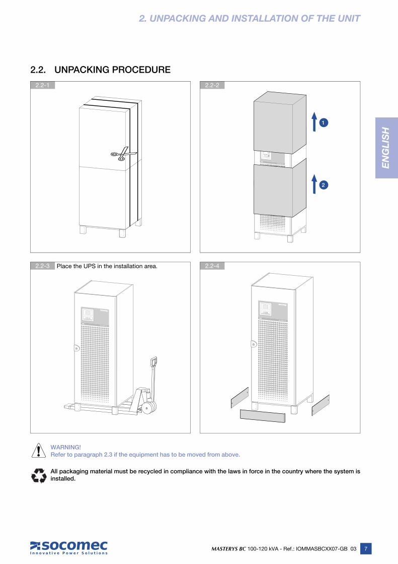
2.2. UNPACKING PROCEDURE
WARNING!Refer to paragraph 2.3 if the equipment has to be moved from above.
All packaging material must be recycled in compliance with the laws in force in the country where the system is installed.
1
2
8 MASTERYS BC 100-120 kVA - Ref.: IOMMASBCXX07-GB 03
2.3.1-1 Remove screws A 2.3.1-2
2.3-1
2. UNPACKING AND INSTALLATION OF THE UNIT
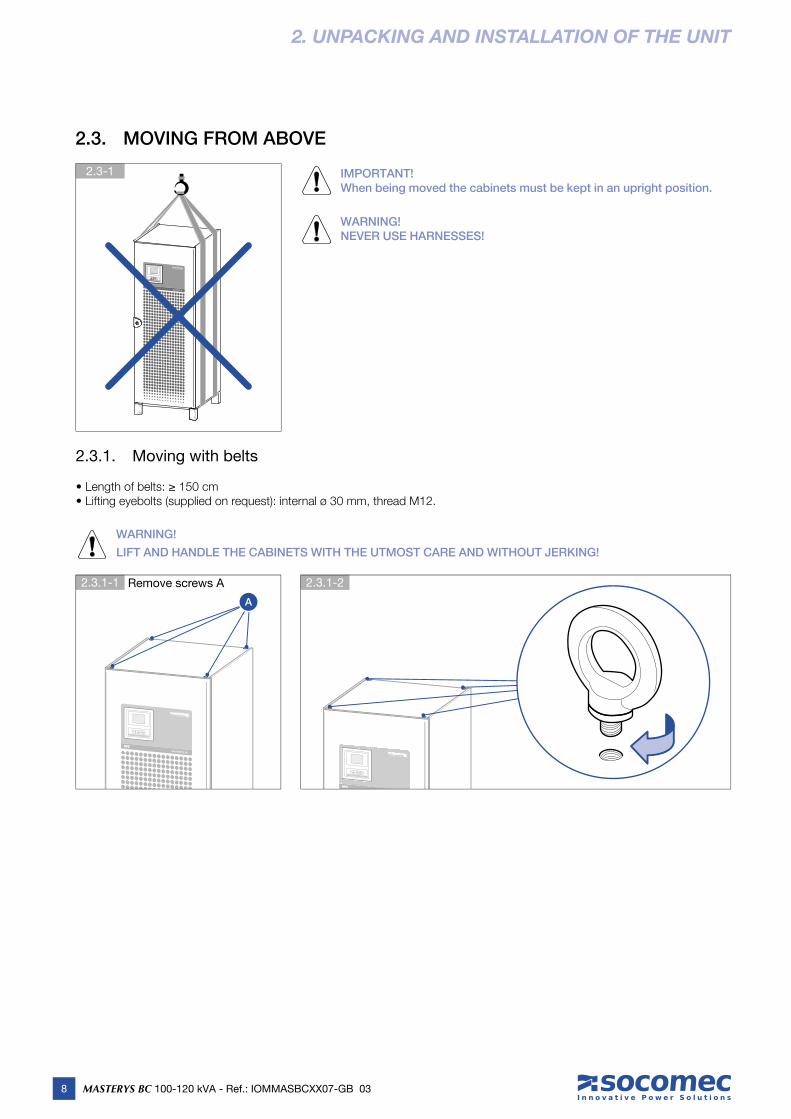
2.3. MOVING FROM ABOVE
IMPORTANT!When being moved the cabinets must be kept in an upright position.
WARNING!NEVER USE HARNESSES!
2.3.1. Moving with belts
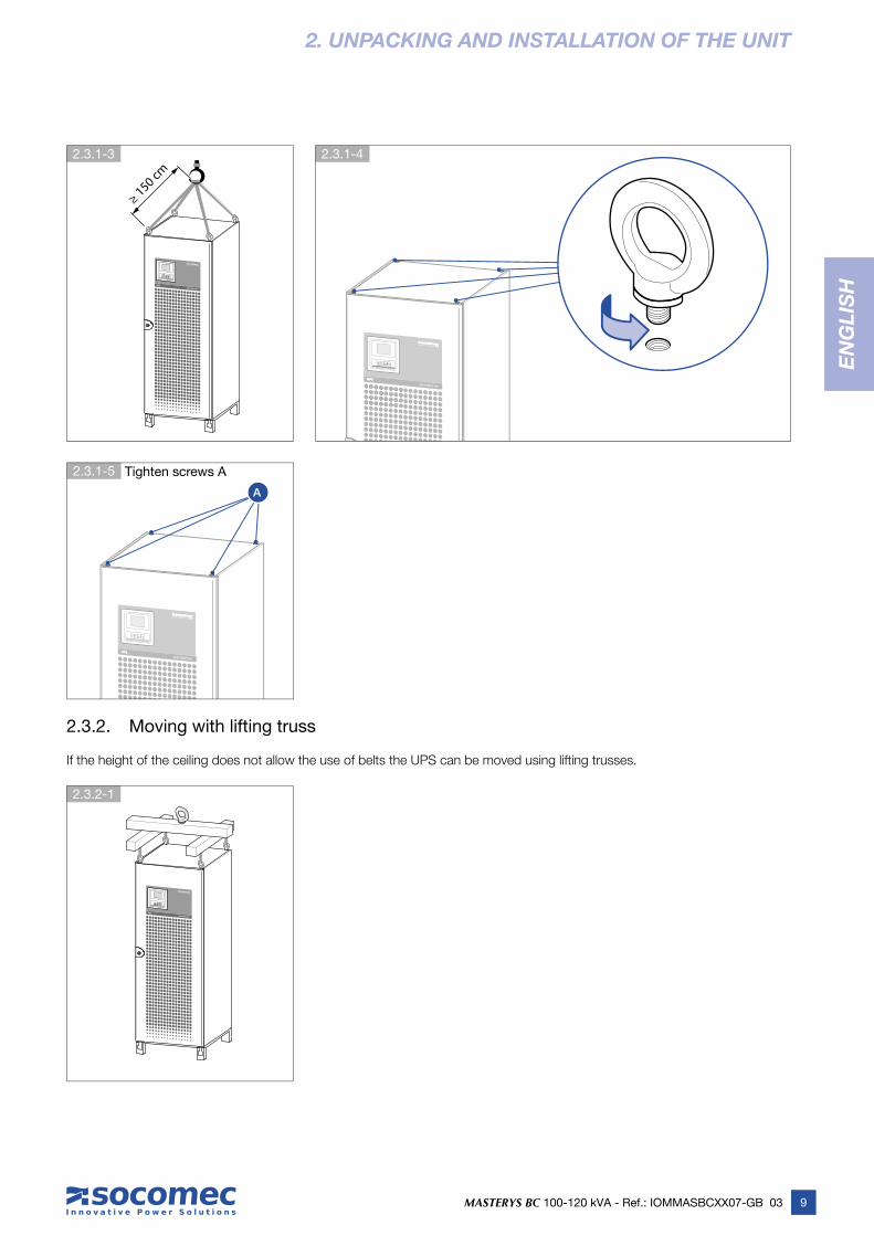
• Length of belts: ≥ 150 cm• Lifting eyebolts (supplied on request): internal ø 30 mm, thread M12.
WARNING!
LIFT AND HANDLE THE CABINETS WITH THE UTMOST CARE AND WITHOUT JERKING!
A
9
EN
GL
ISH
EN
GL
ISH
MASTERYS BC 100-120 kVA - Ref.: IOMMASBCXX07-GB 03
2.3.1-3 2.3.1-4
2.3.1-5 Tighten screws A
2.3.2-1
2. UNPACKING AND INSTALLATION OF THE UNIT
≥ 150 cm
A
2.3.2. Moving with lifting truss
If the height of the ceiling does not allow the use of belts the UPS can be moved using lifting trusses.

10 MASTERYS BC 100-120 kVA - Ref.: IOMMASBCXX07-GB 03
2.4-1
2.4-2 2.4-3
2. UNPACKING AND INSTALLATION OF THE UNIT
2.4. ENVIRONMENTAL REQUIREMENTS
• The UPS is not designed for outdoor use.
• Do not expose the UPS to direct sunlight or sources of excessive heat.
• The recommended operating temperature, humidity and altitude values are listed in the technical specifi cations table (see chapter 10). Cooling systems may be required to maintain these values.
• The UPS must be installed in an environment with no obstructions and which is dry, clean and dust-free.
• Avoid dusty environments or areas where there is dust from conductive or corrosive materials (e.g. metal dust or chemical solutions).
• The UPS can be installed against a wall; the distance will depend on the cables present. The upper part of the UPS must be positioned at least 40 cm away from the ceiling (fi gure 2.4-1).
• The UPS switches are accessed from the front; however, a space of at least 1.5 metres should be left at the front of the UPS for maintenance purposes (fi gure 2.4-1).
• For UPSs set up front-wise, leave a minimum space of 210 cm between the two cabinets so as to allow a passageway when both doors are open (in accordance with standard IEC 60364 - see fi gure 2.4-1).
≥ 4
0 c
m
≥ 210 cm
between the doors
UPS UPS
• Several cabinets can be installed adjacent to each other (fi gure 2.4-2).
• Two MASTERYS BC 100-120 systems can be installed back to back (fi gure 2.4-3).
• Observe the direction of ventilation fl ows (fi gure 2.4-4) and heat dispersion fl ows (fi gure 2.4-5). See chapter 10 for the technical specifi cations relating to required ventilation values.
≥ 10 cm *
UPSBATTERYCABINET
BATTERYCABINET
UPS UPS UPS
* between the backs

11MASTERYS BC 100-120 kVA - Ref.: IOMMASBCXX07-GB 03
EN
GL
ISH
2.4.1-3
2.4.2-1
2.4.1-2
2.4-4 Ventilation 2.4-5 Climate control
2.4.1-1
2. UNPACKING AND INSTALLATION OF THE UNIT
COOLAIR
WARMAIR
CLIM
AT
E C
ON
TR
OL
COOLAIR
WARMAIR
UPS UPS
CLIMATE CONTROL
UPS
2.4.1. Installation on raised fl ooring
If the UPS is to be installed on raised fl ooring the SOCOMEC adjustable frame (fi gure 2.4.1-1) must be used to support the weight of the unit (fi gure 2.4.1-2).
Refer to the relevant installation manual provided in the packaging for information on frame assembly operations.
Allow for small openings in the fl oor panels to ensure air fl ow at the front (fi gure 2.4.1-3).
2.4.2. Installation over a gap
UPS
COOLAIR
COOLAIR
DOOR
12 MASTERYS BC 100-120 kVA - Ref.: IOMMASBCXX07-GB 03
2.5-3 Wrong installation
2.5-2 Permitted installation2.5-1 Correct installation
2. UNPACKING AND INSTALLATION OF THE UNIT
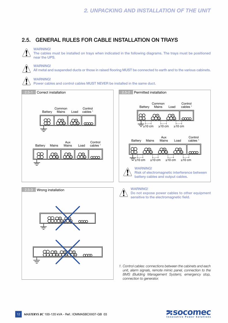
2.5. GENERAL RULES FOR CABLE INSTALLATION ON TRAYS
WARNING!The cables must be installed on trays when indicated in the following diagrams. The trays must be positioned near the UPS.
WARNING!All metal and suspended ducts or those in raised flooring MUST be connected to earth and to the various cabinets.
WARNING!Power cables and control cables MUST NEVER be installed in the same duct.
Common Mains Load
N N
BatteryControl cables 1
MainsAux
Mains
N N
Battery Load
N
Control cables 1
1. Control cables: connections between the cabinets and each unit, alarm signals, remote mimic panel, connection to the BMS (Building Management System), emergency stop, connection to generator.
N N
N N N
WARNING!Do not expose power cables to other equipment sensitive to the electromagnetic field.
WARNING!Risk of electromagnetic interference between battery cables and output cables.
Common Mains Load
N N
Battery
≥10 cm ≥10 cm
Control cables 1
≥10 cm
MainsAux
Mains
N N
Battery Load
N
≥10 cm ≥10 cm ≥10 cm ≥10 cm
Control cables 1
13
EN
GL
ISH
EN
GL
ISH
MASTERYS BC 100-120 kVA - Ref.: IOMMASBCXX07-GB 03
2. UNPACKING AND INSTALLATION OF THE UNIT
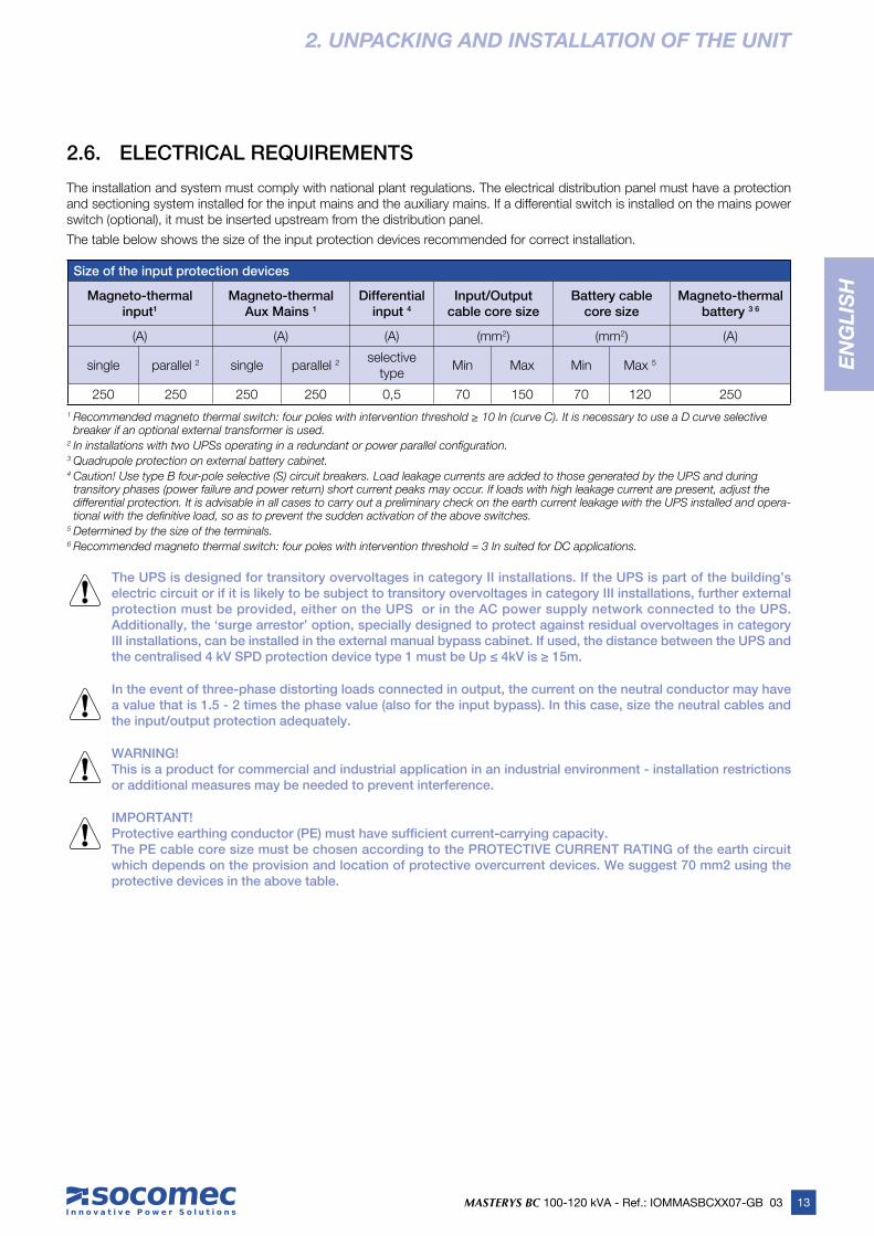
2.6. ELECTRICAL REQUIREMENTS
The installation and system must comply with national plant regulations. The electrical distribution panel must have a protection and sectioning system installed for the input mains and the auxiliary mains. If a differential switch is installed on the mains power switch (optional), it must be inserted upstream from the distribution panel.
The table below shows the size of the input protection devices recommended for correct installation.
Size of the input protection devices
Magneto-thermal input1
Magneto-thermal Aux Mains 1
Differential input 4
Input/Output cable core size
Battery cable core size
Magneto-thermalbattery 3 6
(A) (A) (A) (mm2) (mm2) (A)
single parallel 2 single parallel 2 selective type
Min Max Min Max 5
250 250 250 250 0,5 70 150 70 120 250
1 Recommended magneto thermal switch: four poles with intervention threshold ≥ 10 In (curve C). It is necessary to use a D curve selective breaker if an optional external transformer is used.
2 In installations with two UPSs operating in a redundant or power parallel confi guration.3 Quadrupole protection on external battery cabinet. 4 Caution! Use type B four-pole selective (S) circuit breakers. Load leakage currents are added to those generated by the UPS and during transitory phases (power failure and power return) short current peaks may occur. If loads with high leakage current are present, adjust the differential protection. It is advisable in all cases to carry out a preliminary check on the earth current leakage with the UPS installed and opera-tional with the defi nitive load, so as to prevent the sudden activation of the above switches.
5 Determined by the size of the terminals.6 Recommended magneto thermal switch: four poles with intervention threshold = 3 In suited for DC applications.
The UPS is designed for transitory overvoltages in category II installations. If the UPS is part of the building’s electric circuit or if it is likely to be subject to transitory overvoltages in category III installations, further external protection must be provided, either on the UPS or in the AC power supply network connected to the UPS. Additionally, the ‘surge arrestor’ option, specially designed to protect against residual overvoltages in category III installations, can be installed in the external manual bypass cabinet. If used, the distance between the UPS and the centralised 4 kV SPD protection device type 1 must be Up ≤ 4kV is ≥ 15m.
In the event of three-phase distorting loads connected in output, the current on the neutral conductor may have a value that is 1.5 - 2 times the phase value (also for the input bypass). In this case, size the neutral cables and the input/output protection adequately.
WARNING!This is a product for commercial and industrial application in an industrial environment - installation restrictions or additional measures may be needed to prevent interference.
IMPORTANT!Protective earthing conductor (PE) must have sufficient current-carrying capacity.The PE cable core size must be chosen according to the PROTECTIVE CURRENT RATING of the earth circuit which depends on the provision and location of protective overcurrent devices. We suggest 70 mm2 using the protective devices in the above table.

14 MASTERYS BC 100-120 kVA - Ref.: IOMMASBCXX07-GB 03
2.6.1-1
2. UNPACKING AND INSTALLATION OF THE UNIT
2.6.1. Backfeed protection
F
ACS B.K. B.K.
XB1
XB7
F1VS1
NA1
COM1XB8
NA2
COM2XB9
F
N
XB4XB2 XB3BYPASS INPUT
XB5 XB6
N
F2VS2
The UPS is set up for the installation of external protection devices against the backfeed of dangerous voltages, on both the input power supply line (MAINS SUPPLY) and on the auxiliary backup mains power supply line (AUX MAINS SUPPLY); these devices are controlled by means of the card shown in fi gure 2.6.1-1.
In the event that the equipment does not have a voltage protection device, warning labels must be attached to all mains power disconnectors installed away from the UPS area, in order to remind support personnel that the circuit is connected to a UPS (see also paragraph 1.1 of this manual and paragraph 4.5.3 of standard EN62040-1 2009-05). The label is supplied with the equipment.
If under certain irregular conditions, or due to the installation upstream (e.g. undetected and protected earth fault, or high leakage in a phase, or with IT systems) there is a hazardous potential on neutral, a suitable isolating switch must be provided on the neutral as well, or else there must be a detection, signalling and protection system (see the table in section 2.6 Electrical requirements).
Connections, refer to paragraph 2.7.5.
15
EN
GL
ISH
EN
GL
ISH
MASTERYS BC 100-120 kVA - Ref.: IOMMASBCXX07-GB 03
2.7-1
2. UNPACKING AND INSTALLATION OF THE UNIT
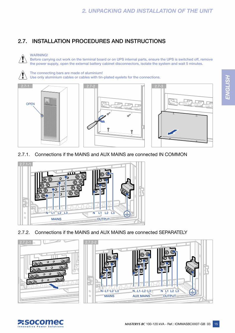
2.7. INSTALLATION PROCEDURES AND INSTRUCTIONS
WARNING!Before carrying out work on the terminal board or on UPS internal parts, ensure the UPS is switched off, remove the power supply, open the external battery cabinet disconnectors, isolate the system and wait 5 minutes.
The connecting bars are made of aluminium!Use only aluminium cables or cables with tin-plated eyelets for the connections.
2.7.1. Connections if the MAINS and AUX MAINS are connected IN COMMON
OPENOPEN
2.7.2. Connections if the MAINS and AUX MAINS are connected SEPARATELY
MAINSMAINS
AUX MAINSAUX MAINSMAINSMAINS OUTPUTOUTPUT
NN L1L1 L2L2 L3L3 NN L1L1 L2L2 L3L3
NN L1L1 L2L2 L3L3NN L1L1 L2L2 L3L3 NN L1L1 L2L2 L3L3
2.7.1-1
2.7.2-2 2.7.2-1
2.7-2 2.7-3
OUTPUTOUTPUT

16 MASTERYS BC 100-120 kVA - Ref.: IOMMASBCXX07-GB 03
2. UNPACKING AND INSTALLATION OF THE UNIT
2.7.3. EXTERNAL BATTERY CABINET connection
WARNING!Before carrying out any operations, ensure that:• the battery fuses located inside the battery cabinet are open;• the UPS is not live and all mains or battery switches are open;• the switches upstream of the UPS are open.
Use double insulated cables or the cables supplied with the unit to connect the UPS to the Battery cabinet.
Cabling errors with inversion of battery polarity may cause permanent damage to the equipment.
If using cabinets not supplied by the UPS manufacturer, it is the installer’s responsibility to check the electrical compatibility and presence of appropriate protection devices between the UPS and the battery cabinet (fuses and switches of sufficient capacity to protect the cables from the UPS to the battery cabinet). As soon as the UPS is switched on (before closing the battery switches) the battery parameters must be verified accordingly (voltage, capacity, number of elements, etc.) on the mimic panel menu. See 5.3.6 paragraph for battery settings configuration.
In the case of external batteries, the minimum number of elements permitted is 20 per branch for 120 kVA and 19 per branch for 100 kVA.
2.7.3-1
B1−B1−
B1+B1+
B2−B2−
B2+B2+
2.7.3-2 BATTERY STRING No. 1 2.7.3-3 BATTERY STRING No. 2
17MASTERYS BC 100-120 kVA - Ref.: IOMMASBCXX07-GB 03
EN
GL
ISH
2.7.4-1 2.7.4-2
2. UNPACKING AND INSTALLATION OF THE UNIT
OUT2
OUT3
IN1OUT1
OUT4
IN1IN2
IN3
IN3IN3
temperature temperature probeprobe
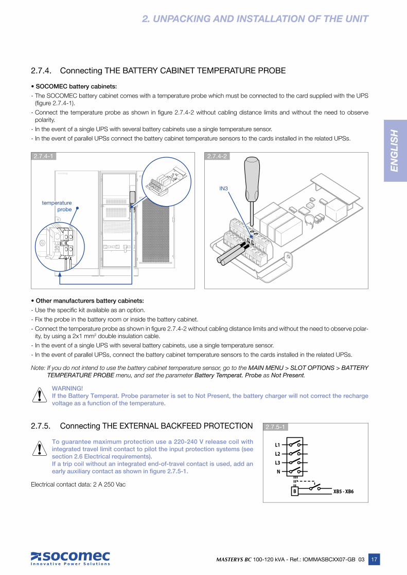
2.7.4. Connecting THE BATTERY CABINET TEMPERATURE PROBE
• SOCOMEC battery cabinets:
- The SOCOMEC battery cabinet comes with a temperature probe which must be connected to the card supplied with the UPS (fi gure 2.7.4-1).
- Connect the temperature probe as shown in fi gure 2.7.4-2 without cabling distance limits and without the need to observe polarity.
- In the event of a single UPS with several battery cabinets use a single temperature sensor.
- In the event of parallel UPSs connect the battery cabinet temperature sensors to the cards installed in the related UPSs.
• Other manufacturers battery cabinets:
- Use the specifi c kit available as an option.
- Fix the probe in the battery room or inside the battery cabinet.
- Connect the temperature probe as shown in fi gure 2.7.4-2 without cabling distance limits and without the need to observe polar-ity, by using a 2x1 mm2 double insulation cable.
- In the event of a single UPS with several battery cabinets, use a single temperature sensor.
- In the event of parallel UPSs, connect the battery cabinet temperature sensors to the cards installed in the related UPSs.
Note: If you do not intend to use the battery cabinet temperature sensor, go to the MAIN MENU > SLOT OPTIONS > BATTERY TEMPERATURE PROBE menu, and set the parameter Battery Temperat. Probe as Not Present.
WARNING!If the Battery Temperat. Probe parameter is set to Not Present, the battery charger will not correct the recharge voltage as a function of the temperature.
2.7.5. Connecting THE EXTERNAL BACKFEED PROTECTION
To guarantee maximum protection use a 220-240 V release coil with integrated travel limit contact to pilot the input protection systems (see section 2.6 Electrical requirements). If a trip coil without an integrated end-of-travel contact is used, add an early auxiliary contact as shown in figure 2.7.5-1.
Electrical contact data: 2 A 250 Vac
OUT2
OUT3
IN1IN3OUT1
OUT4
IN1IN2
2.7.5-1
B
L1
L2
L3
XB5 - XB6
N

18 MASTERYS BC 100-120 kVA - Ref.: IOMMASBCXX07-GB 03
2.7.5-4
2.7.5-3 2.7.5-2
2. UNPACKING AND INSTALLATION OF THE UNIT
F
ACS B.K. B.K.
XB1
B.K.
XB7
F1VS1
NA1
COM1XB8
NA2
COM2XB9
F
N230 V
BYPASS
B.K.INPUT
XB4XB2 XB3BYPASS INPUT
XB5 XB6
N
F2VS2 F
ACSB.K.
B.K.
XB1
XB7
F1NA1
COM1XB8
NA2
B.K.BYPASS
XB4
BYPASSINPUT
NF N
F N
VS2
Key
A Distribution panel
B Trip coil
X10 Mains terminal board
X40 Aux Mains terminal board
MAINS Mains switch
AUX MAINS Aux Mains switch
XB5 Aux Mains BKF connector
XB6 Mains BKF connector
AUX MAINS AUX MAINS protectionprotection
MAINSMAINSprotectionprotection
Activating UPS protection on the mimic panel: access the MAIN MENU > SETTINGS > UPS SETTINGS > BACKFEED and set the parameter Backfeed Type to Separate Mains.
A UPS
AUX MAINS X40
BKF
XB6
XB5
MAINS
B
B
X10
L1
L2
L3
N
L1
L2
L3
N
L1
L2
L3
N
L1
L2
L3
N
• Separate Mains

19MASTERYS BC 100-120 kVA - Ref.: IOMMASBCXX07-GB 03
EN
GL
ISH
2.7.5-5 2.7.5-6
2.7.5-7
2. UNPACKING AND INSTALLATION OF THE UNIT
FACS
B.K.B.K.
XB1
XB7
F1NA1
COM1XB8
NA2
B.K.BYPASS
XB4
BYPASSINPUT
NF N
F N
VS2
Common Mains Common Mains protectionprotection
• Common Mains
F
ACS B.K. B.K.
XB1
B.K.
XB7
F1VS1
NA1
COM1XB8
NA2
COM2XB9
F
N230 V
BYPASS
B.K.INPUT
XB4XB2 XB3BYPASS INPUT
XB5 XB6
N
F2VS2
Key
A Distribution panel
B Trip coil
X10 Mains terminal board
X40 Aux Mains terminal board
COMMON MAINS Mains switch
XB5 Aux Mains BKF connector
XB6 Mains BKF connector
Activating UPS protection on the mimic panel: access the MAIN MENU > SETTINGS > UPS SETTINGS > BACKFEED and set the parameter Backfeed Type to Common Mains.A UPS
X40
BKF
COMMON MAINS
B
X10
L1
L2
L3
N
L1
L2
L3
N
L1
L2
L3
N
XB6
XB5
2.7.6. INTERNAL BACKFEED PROTECTION
If the UPS has internal backfeed protection:• there is no need for external backfeed protection;• connect the UPS as indicated in paragraph 4.4;• the switches should be set as shown in figure 2.7.6-1.
Q1 Q4 Q5 Q3
2.7.6-1
20 MASTERYS BC 100-120 kVA - Ref.: IOMMASBCXX07-GB 03
2. UNPACKING AND INSTALLATION OF THE UNIT
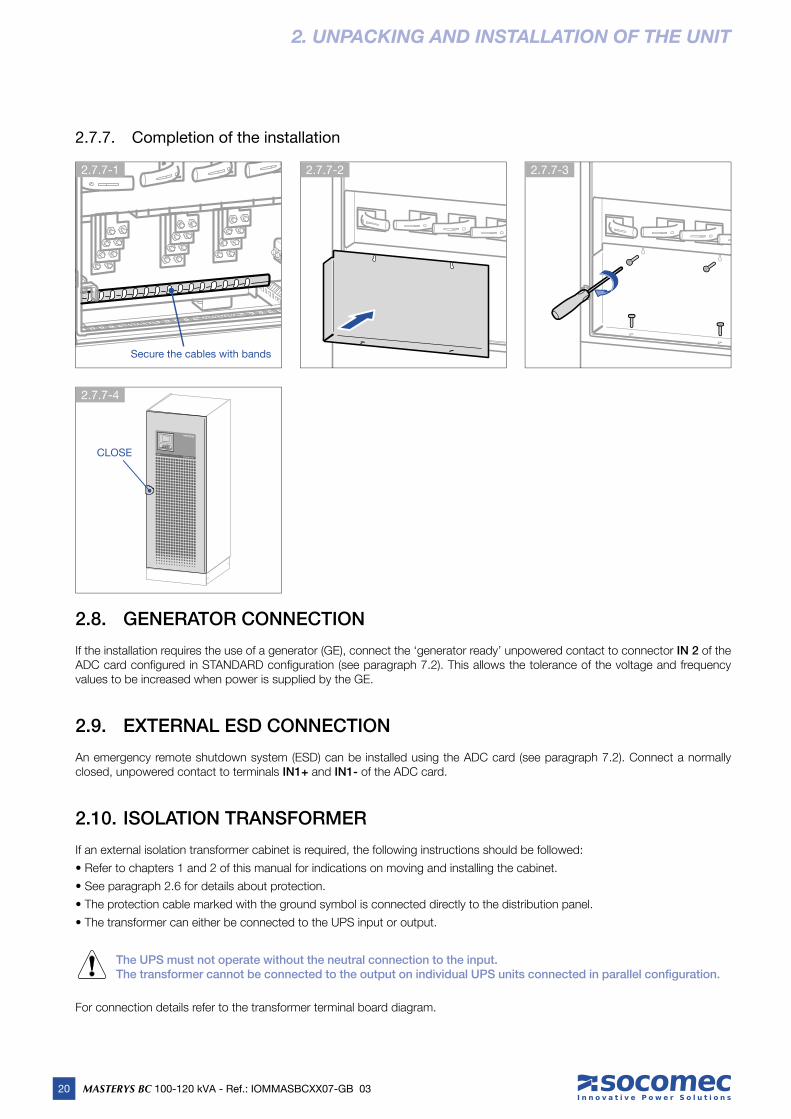
2.7.7. Completion of the installation
2.8. GENERATOR CONNECTION
If the installation requires the use of a generator (GE), connect the ‘generator ready’ unpowered contact to connector IN 2 of the ADC card confi gured in STANDARD confi guration (see paragraph 7.2). This allows the tolerance of the voltage and frequency values to be increased when power is supplied by the GE.
2.9. EXTERNAL ESD CONNECTION
An emergency remote shutdown system (ESD) can be installed using the ADC card (see paragraph 7.2). Connect a normally closed, unpowered contact to terminals IN1+ and IN1- of the ADC card.
2.10. ISOLATION TRANSFORMER
If an external isolation transformer cabinet is required, the following instructions should be followed:
• Refer to chapters 1 and 2 of this manual for indications on moving and installing the cabinet.
• See paragraph 2.6 for details about protection.
• The protection cable marked with the ground symbol is connected directly to the distribution panel.
• The transformer can either be connected to the UPS input or output.
The UPS must not operate without the neutral connection to the input.The transformer cannot be connected to the output on individual UPS units connected in parallel configuration.
For connection details refer to the transformer terminal board diagram.
Secure the cables with bandsSecure the cables with bands
2.7.7-1 2.7.7-2 2.7.7-3
CLOSECLOSE
2.7.7-4

21MASTERYS BC 100-120 kVA - Ref.: IOMMASBCXX07-GB 03
EN
GL
ISH
2. UNPACKING AND INSTALLATION OF THE UNIT
2.11. UPS PARALLEL CONFIGURATION
• Parallel connection enhances UPS system reliability, performance and power.
• Operating UPSs are connected to each other by a signal cable B (Fig. 2.11.1-1) which provides a maximum distance between UPSs of approx. 3 metres and enables the external battery cabinet to be inserted next to each UPS. They are confi gured differ-ently depending on the position they are assigned; for this reason the units have a position label:
- the LEFT label means the unit must be positioned to the left.
- the RIGHT label means the unit must be positioned to the right.
• The power supply of each UPS must be equipped with a protection device as shown in the table in paragraph 2.6.
• The cross section and length of the input and output cables must be identical for all units.
• Phase rotation must be the same for each unit connected in parallel and also on any external manual bypass line.
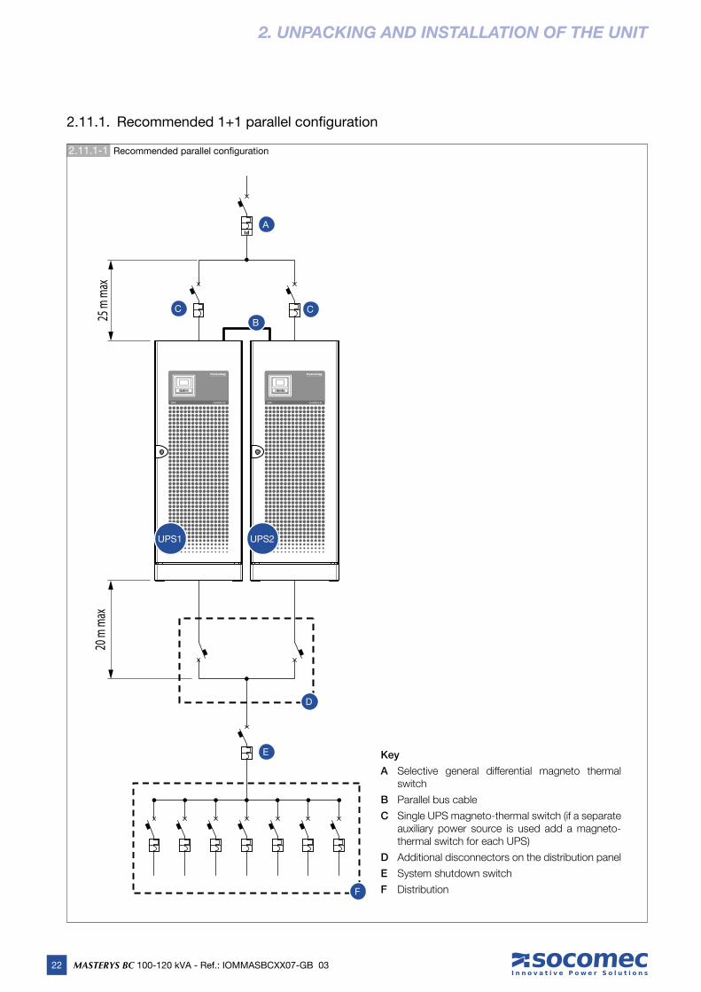
• Cables of the same length and cross section must be used for the connection between the general power switch A, the switches C and the respective UPS units. The length of the cables from A to each UPS module must not exceed 25 metres (Fig. 2.11.1-1).
• The cables from the UPS module to circuit breaker D must be of the same length (max. 20 m with multi-core cables).
• If a differential switch is installed on the mains power switch, it must be inserted upstream from the distribution panel; it must be a selective type and the trigger value must be 0.5 A multiplied by the number of UPSs connected in parallel.
Only activate circuit breaker D after turning off the UPS.
• In order for units connected in a parallel confi guration to operate correctly, control cables are required to exchange data between both UPS units making up the parallel system. The cables in question are supplied with the UPS in the case of a standard paral-lel setup or are attached to the parallel kit in the case of a later system upgrade.
WARNING!Parallel configuration must only be activated by SOCOMEC qualified personnel.
22 MASTERYS BC 100-120 kVA - Ref.: IOMMASBCXX07-GB 03
2. UNPACKING AND INSTALLATION OF THE UNIT
2.11.1-1 Recommended parallel confi guration
Key
A Selective general differential magneto thermal switch
B Parallel bus cable
C Single UPS magneto-thermal switch (if a separate auxiliary power source is used add a magneto-thermal switch for each UPS)
D Additional disconnectors on the distribution panel
E System shutdown switch
F Distribution
20 m
max
25 m
max
A
UPS1 UPS2
B
C C
D
E
F
2.11.1. Recommended 1+1 parallel confi guration

23MASTERYS BC 100-120 kVA - Ref.: IOMMASBCXX07-GB 03
EN
GL
ISH
2. UNPACKING AND INSTALLATION OF THE UNIT
2.11.1-3
1+1 Parallel confi guration - Common Mains
1+1 Parallel confi guration - Separate Mains
2.11.1-2
UPS1 UPS2
OUTPUT1
MAINS1
OUTPUT2
MAINS2
UPS1 UPS2
OUTPUT1
MAINS1
OUTPUT2
MAINS2
AUX MAINS
1
AUX MAINS
2
24 MASTERYS BC 100-120 kVA - Ref.: IOMMASBCXX07-GB 03
2. UNPACKING AND INSTALLATION OF THE UNIT
2.12. SPECIAL PARALLEL CONFIGURATION FEATURES
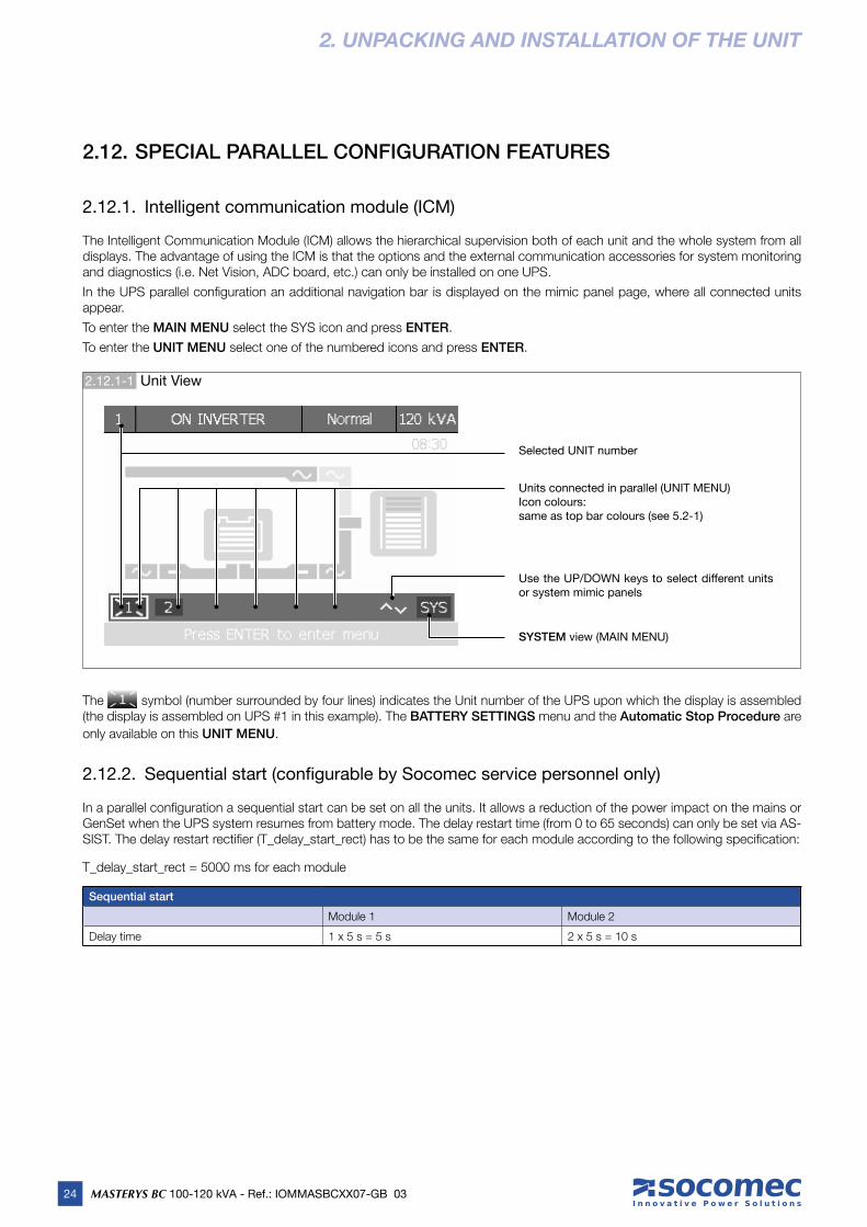
2.12.1. Intelligent communication module (ICM)
The Intelligent Communication Module (ICM) allows the hierarchical supervision both of each unit and the whole system from all displays. The advantage of using the ICM is that the options and the external communication accessories for system monitoring and diagnostics (i.e. Net Vision, ADC board, etc.) can only be installed on one UPS.
In the UPS parallel confi guration an additional navigation bar is displayed on the mimic panel page, where all connected units appear.
To enter the MAIN MENU select the SYS icon and press ENTER.
To enter the UNIT MENU select one of the numbered icons and press ENTER.
Use the UP/DOWN keys to select different units or system mimic panels
SYSTEM view (MAIN MENU)
Selected UNIT number
Units connected in parallel (UNIT MENU)Icon colours:same as top bar colours (see 5.2-1)
2.12.1-1 Unit View
The symbol (number surrounded by four lines) indicates the Unit number of the UPS upon which the display is assembled (the display is assembled on UPS #1 in this example). The BATTERY SETTINGS menu and the Automatic Stop Procedure are
only available on this UNIT MENU.
2.12.2. Sequential start (confi gurable by Socomec service personnel only)
In a parallel confi guration a sequential start can be set on all the units. It allows a reduction of the power impact on the mains or GenSet when the UPS system resumes from battery mode. The delay restart time (from 0 to 65 seconds) can only be set via AS-SIST. The delay restart rectifi er (T_delay_start_rect) has to be the same for each module according to the following specifi cation:
T_delay_start_rect = 5000 ms for each module
Sequential start
Module 1 Module 2
Delay time 1 x 5 s = 5 s 2 x 5 s = 10 s

25MASTERYS BC 100-120 kVA - Ref.: IOMMASBCXX07-GB 03
EN
GL
ISH
3. MODES OF OPERATION
3.1. ONLINE OPERATION
A special feature of the MASTERYS BC series is the ON LINE double conversion in conjunction with low distortion mains power absorption. In Normal Mode (on inverter) the UPS can supply a voltage that is fully stabilised in frequency and amplitude, regard-less of any interference in the mains power supply, within the most stringent classifi cation of UPS regulations.
ONLINE operation provides three operating modes according to mains and load conditions:
• Inverter mode
This is the most frequent operating condition: energy is drawn from the primary mains power supply and converted and used by the inverter to generate the output voltage to power the connected loads.
The inverter is constantly synchronised in frequency with the auxiliary mains to enable load transfer (due to an overload or inverter shutdown) without any break in the power supply to the load.
The battery charger supplies the energy required to maintain or recharge the battery.
• Bypass mode
In the event of inverter failure the load is automatically transferred onto the auxiliary mains without any interruption in the power supply. This procedure may occur in the following situations:
- in the event of a temporary overload, the inverter continues to power the load. If the condition persists, the UPS output is switched on to the auxiliary mains via automatic bypass. Normal operation, which is from the inverter, returns automatically a few seconds after the overload disappears.
- when the voltage generated by the inverter goes outside the limits due to a major overload or a fault on the inverter.
- when the internal temperature exceeds the maximum value allowed.
• Battery mode
In the event of a mains failure (micro interruptions or extended power cuts), the UPS continues to power the load using the energy stored in the battery.
3.2. OPERATION IN HIGH EFFICIENCY MODE
The UPS allows the selection of a programmable economy operating mode (Eco Mode) that can increase overall effi ciency by up to 99% for energy saving purposes. If the power supply fails the UPS will automatically switch onto the inverter and continue to supply power to the load by drawing energy from the battery.
This mode does not provide perfect stability in frequency and voltage as the Normal mode does. Therefore the use of this mode should be carefully evaluated according to the level of protection required by the application.
With the optional board Net Vision (see chapter 7.7) specifi c daily or weekly time intervals can be selected and programmed to power applications directly from the auxiliary mains.
Eco Mode operation provides very high effi ciency, since the application is powered directly from the auxiliary mains via the auto-matic bypass under normal operating conditions.
To activate Eco Mode go to MAIN MENU > COMMANDS > ECO MODE and select Activate Eco Mode. To disable Eco Mode, select Return to Normal Mode.

26 MASTERYS BC 100-120 kVA - Ref.: IOMMASBCXX07-GB 03
3.4-1 3-phase input/3-phase output for UPS 3/3
3.3. OPERATION IN CONVERTER MODE
In converter mode the UPS can supply a fully stabilised sinusoidal output voltage with a different frequency from the input power line (50Hz or 60Hz is available as output frequency value).
IMPORTANT!Only set this mode on UPS units with the auxiliary mains (AUX MAINS) disconnected! Do not set this mode on UPS units with common mains lines as it could damage the load!
3.4. OPERATION WITH EXTERNAL MANUAL BYPASS (optional)
The external maintenance bypass may be placed on the general distribution panel when the UPS is installed, or by installing the bypass panel that is supplied on request.
The Q1 switch must be connected to the auxiliary mains input and the mains input must be isolated on the panel.
If the manual bypass is activated (with the appropriate procedure), the load is powered directly from the auxiliary mains, while the UPS is in fact excluded from the power supply and can be switched off.
This operating mode is useful when maintenance needs to be carried out on the UPS since service personnel can work on the installation without having to cut off the power supply to the load.
3. MODES OF OPERATION
Key
Q1 Mains power switch (MAINS)
Q3 Ouput switch
Q5 Bypass switch
Bypass panel connection diagram
MainsL3L2L1
L3L2L1
L1
N
NLoad
IN
UPS
N
L1L2 L2L3 L3
N
OUT
Q5
Q1
Q3
3.5. OPERATION WITH INTERNAL MAINTENANCE BYPASS
If the internal maintenance bypass is activated using the appropriate procedure the load is powered directly from the maintenance bypass, while the UPS is separate from the power supply and can be switched off.
This operating mode can be selected for maintenance to be carried out on the system, so that the necessary actions can be
performed by service personnel without having to disconnect the power supply to the load.
3.6. OPERATION WITH MOTOR GENERATOR (GENSET)
MASTERYS BC can be operated in conjunction with a generator (GENSET) over the ADC interface (see chapter 8.1).
With a generator, the frequency and voltage ranges of the auxiliary mains can be increased to accept the instability of the GE and to also avoid operation from the battery or risks of out-of-synchronisation switching on to the bypass.
27MASTERYS BC 100-120 kVA - Ref.: IOMMASBCXX07-GB 03
EN
GL
ISH
4. ACCESS TO CONTROLS
4.1. IDENTIFYING SWITCHING AND CONNECTION POINTS
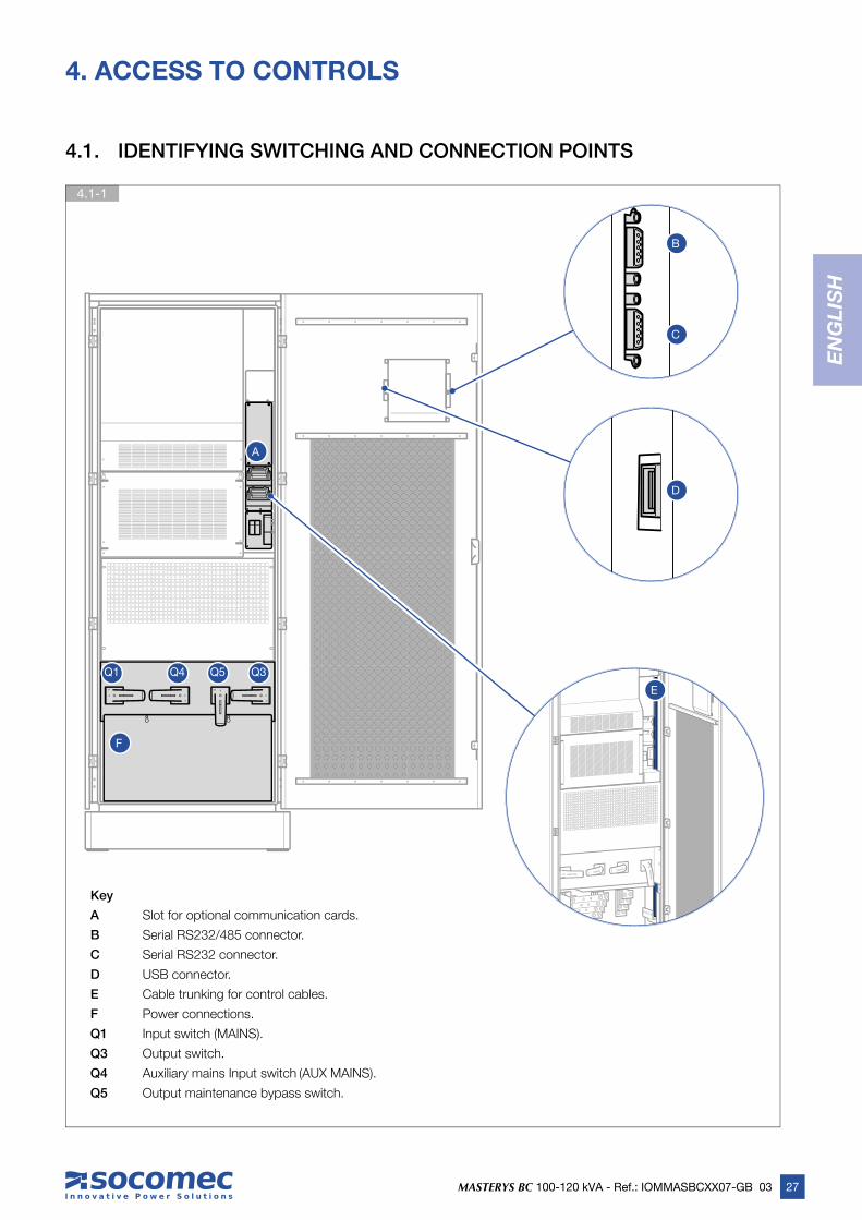
Key
A Slot for optional communication cards.
B Serial RS232/485 connector.
C Serial RS232 connector.
D USB connector.
E Cable trunking for control cables.
F Power connections.
Q1 Input switch (MAINS).
Q3 Output switch.
Q4 Auxiliary mains Input switch (AUX MAINS).
Q5 Output maintenance bypass switch.
Q1 Q4 Q5 Q3
A
F
E
B
D
C
4.1-1
28 MASTERYS BC 100-120 kVA - Ref.: IOMMASBCXX07-GB 03
5.1-1 3-phase input/3-phase output for UPS 3/3
5. HUMAN MACHINE INTERFACE
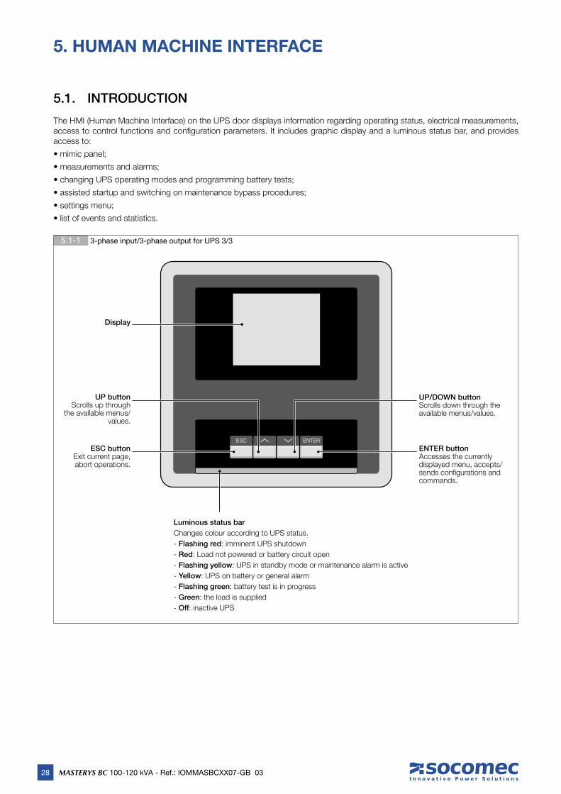
5.1. INTRODUCTION
The HMI (Human Machine Interface) on the UPS door displays information regarding operating status, electrical measurements, access to control functions and confi guration parameters. It includes graphic display and a luminous status bar, and provides access to:
• mimic panel;
• measurements and alarms;
• changing UPS operating modes and programming battery tests;
• assisted startup and switching on maintenance bypass procedures;
• settings menu;
• list of events and statistics.
Display
ESC buttonExit current page, abort operations.
UP buttonScrolls up through
the available menus/values.
UP/DOWN buttonScrolls down through the available menus/values.
ENTER buttonAccesses the currently displayed menu, accepts/sends confi gurations and commands.
Luminous status bar
Changes colour according to UPS status.
- Flashing red: imminent UPS shutdown
- Red: Load not powered or battery circuit open
- Flashing yellow: UPS in standby mode or maintenance alarm is active
- Yellow: UPS on battery or general alarm
- Flashing green: battery test is in progress
- Green: the load is supplied
- Off: inactive UPS

29
EN
GL
ISH
EN
GL
ISH
MASTERYS BC 100-120 kVA - Ref.: IOMMASBCXX07-GB 03
5.2-3 Status icons
5.2-2 Alarms area
5.2-1 Status bar (always displayed)
5. HUMAN MACHINE INTERFACE
UPS Rated Power (kVA)
Unit panel reference
Operating modes:Normal (Normal mode), Eco (Eco mode), En. Saver (Energy Saver mode – parallel confi gurations only), Standby (Standby program mode), Service.
Alarms areaPresent when an alarm is active.Enter ALARMS menu to display the complete alarms list (see chapter 9).
Key icon:Displayed if the keypad has been locked.
Time:UPS current time (hours and minutes, with ':' fl ashing).
USB icon:Displayed if a USB memory stick is inserted.It must be formatted with FAT32 fi le system.
Foreword: Status icons and Time are only visible if there are no pending alarms, as the alarm bar overwrites the icons when active.
Unit status:• Displayed messages: ON MAINT. BYPASS, IMMINENT STOP,
ON BATTERY, BATTERY TEST, ON INVERTER, ON AUTO BYPASS, UNIT AVAILABLE, UPS ON STANDBY, LOAD OFF.
- Flashing: imminent UPS shutdown- Black: Load not powered or battery circuit open
5.2. MIMIC PANEL OVERVIEW

30 MASTERYS BC 100-120 kVA - Ref.: IOMMASBCXX07-GB 03
5.2-4 Additional Icons
5.2-5 Mimic panel
5. HUMAN MACHINE INTERFACE
On Maintenance Bypass
Commissioning Code not insert (see chapter 5.3.) or Scheduled Inspection warning: machine inspection required.Call SOCOMEC support service
Operating on GenSet
Bypass mode (or Eco Mode) not possible
Bars1. Rectifi er input.2. Rectifi er output.3. Inverter Input or Battery Output.4. Inverter Output.5. Unit output.6. Output from static switch7. Bypass input.
Bar colour identifi es energy fl ow:• dark grey: active/mains present• light grey: mains not present
6 7
5
3 2 1 4
Keypad locking
The keypad can be locked by pressing the buttons in the following sequence:
ESC UP DOWN ENTER
To unlock the keypad, the buttons must be pressed in the reverse sequence:
ENTER DOWN UP ESC
These sequences work only on Mimic Panel page.
31MASTERYS BC 100-120 kVA - Ref.: IOMMASBCXX07-GB 03
EN
GL
ISH
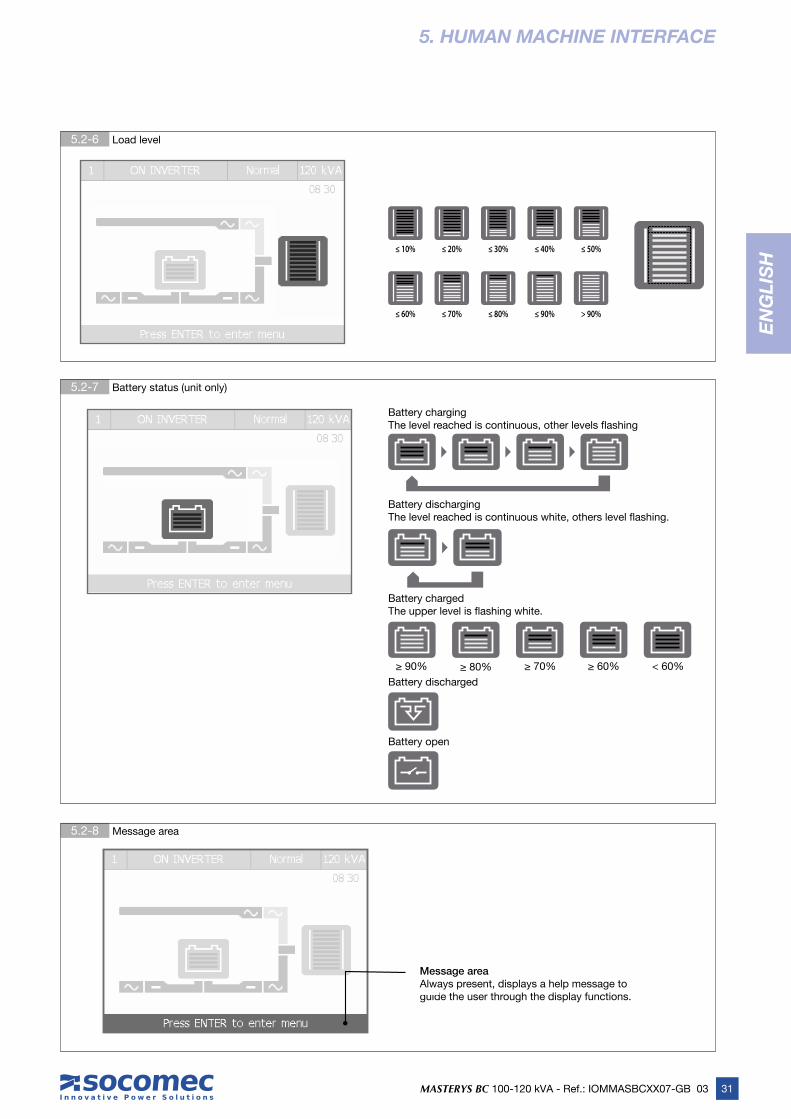
5.2-8 Message area
5.2-7 Battery status (unit only)
5.2-6 Load level
5. HUMAN MACHINE INTERFACE
≤ 10% ≤ 20% ≤ 30% ≤ 40% ≤ 50%
≤ 60% ≤ 70% ≤ 80% ≤ 90% > 90%
Battery chargingThe level reached is continuous, other levels fl ashing
Battery discharging The level reached is continuous white, others level fl ashing.
Battery charged The upper level is fl ashing white.
Battery discharged
Battery open
≥ 90% ≥ 80% ≥ 70% ≥ 60% < 60%
Message areaAlways present, displays a help message to guide the user through the display functions.
32 MASTERYS BC 100-120 kVA - Ref.: IOMMASBCXX07-GB 03
5. HUMAN MACHINE INTERFACE
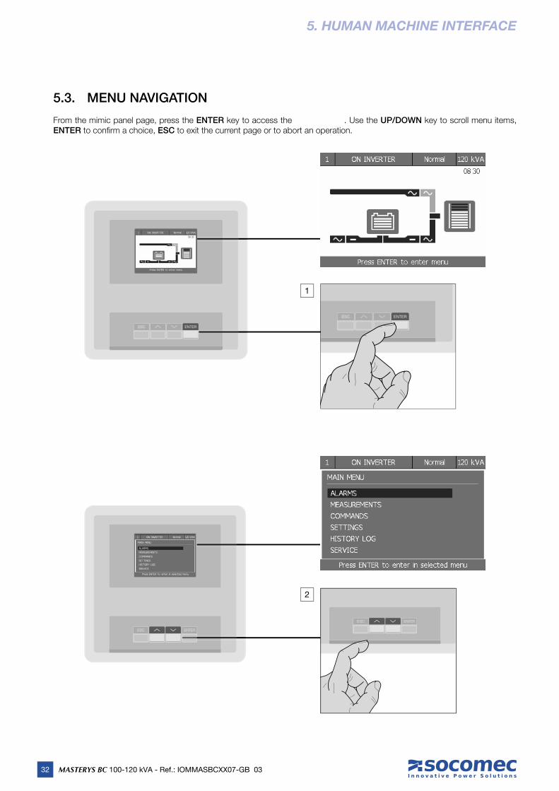
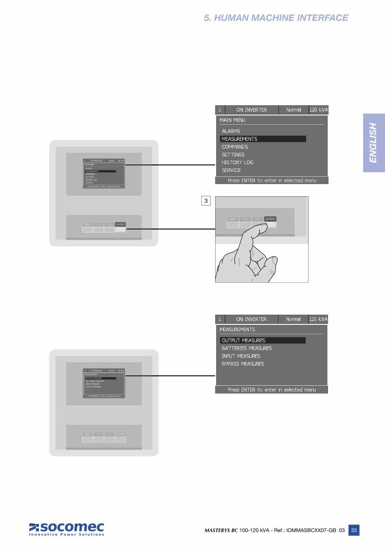
5.3. MENU NAVIGATION
From the mimic panel page, press the ENTER key to access the . Use the UP/DOWN key to scroll menu items, ENTER to confi rm a choice, ESC to exit the current page or to abort an operation.
1
2
33MASTERYS BC 100-120 kVA - Ref.: IOMMASBCXX07-GB 03
EN
GL
ISH
5. HUMAN MACHINE INTERFACE
3

34 MASTERYS BC 100-120 kVA - Ref.: IOMMASBCXX07-GB 03
5. HUMAN MACHINE INTERFACE
5.3.1. Entering passwords
Some operations and settings require a password in order to be performed. If this is the case a padlock is displayed at the top right of the page. After inserting a valid password the padlock opens and the operation can be performed.
When a password is required a virtual keyboard is displayed. The default password is MAST.
5.3.2. ALARMS menu
This menu displays all pending UPS alarms. Use the ALARMS RESET command in the COMMANDS menu to reset alarms.
If there is more than one page press UP/DOWN to scroll pages.
5.3.3. MEASUREMENTS menu
This menu displays all UPS measurements relating to the input stage, output stage, batteries and auxiliary mains (bypass).
If there is more than one page press UP/DOWN to scroll pages.
5.3.4. COMMANDS menu
This menu contains the commands that can be sent to the UPS. Some of them are password protected.
If a command is not available a command failure message appears.
5.3.5. SETTINGS menu
This menu contains all the machine settings. There are the following sub-menus:
• PREFERENCES: user preferences such as language, date and time, display brightness, buzzer;
• UPS SETTINGS: critical machine settings for output, batteries and trasformer.
Wrong configuration in UPS SETTINGS could damage the load or the batteries.
• CONNECTIVITY: confi gurations of communication options;
• SLOT OPTIONS: confi gurations of available optional boards, which can be fi tted to the front slots.
System critical parameters are password protected and should be modifi ed by specialist personnel only.
5.3.1-1
Quit without saving
Switch to numeric and symbol keypad
Delete
Confi rm
Select next key
Select previous key
Confi rm the selected key/insert the selected char

35MASTERYS BC 100-120 kVA - Ref.: IOMMASBCXX07-GB 03
EN
GL
ISH
5. HUMAN MACHINE INTERFACE
5.3.6. BATTERY SETTINGS MENU
This is the menu for battery confi guration. The list can be scrolled down to see the full list of battery settings. If batteries are not available only the fi rst element of the list is shown. When one of the battery settings is edited all settings below in the list have to be checked and confi rmed. The battery settings are saved only when the last battery setting is confi rmed.
To change battery confi gurations enter the menu: MAIN MENU > SETTINGS > UPS SETTINGS > BATTERIES.
In the case of UPSs connected in parallel enter the menu: UNIT MENU > BATTERY SETTINGS.
These parameters for battery settings are critical: number of cells, capacity, charge current.Risk of damage for load or batteries.
5.3.7. HISTORY LOG menu
EVENT LIST menu: it shows the list of UPS alarms and events that have occurred. The last 150 events can be displayed. Press UP/DOWN to scroll the list.
STATISTICS menu: the system reports some measurements (output load, input apparent power, internal temperature) in graphi-cal format. These values can be used to analyse the situation over the last 14 days or in shorter periods (last 24 hours, last hour or last minute). Enter the required menu and press UP/DOWN to scroll through different periods. The last page shows the minimum, maximum and average values of the selected measurement. This information provides an enhanced evaluation of the operating mode of the equipment in order to verify whether certain critical operating situations are recurrent or only occasional.
COUNTERS menu: provides the number of events (occurred in the last 14 days) of switches on battery, overloads and the num-ber of working hours on genset.
5.3.8. SERVICE menu
This menu is reserved for support service personnel and holds the UPS identifi cation data, the utilities for the SW upgrade, and the utilities for the download of reports to an USB key.
5.3.9. COMMISSIONING CODE
To complete equipment activation a warranty activation code is requested. To insert the Commissioning Code go to MAIN MENU > SERVICE > COMMISSIONING CODE.
If the Commissioning Code is not inserted an alarm symbol is shown on the mimic panel ( ).
The Commissioning Code is provided directly by the reference Support Centre upon communication of the serial number. When contact is made with the Support Centre for the Commissioning Code, detailed information can be obtained on the UPS func-tions available and on regular preventive maintenance programmes.
5.3.10. BATTERY SETTINGS MENU
This is the menu for battery confi guration. The list can be scrolled down to see the full list of battery settings. If batteries are not available only the fi rst element of the list is shown. When one of the battery settings is edited all settings below in the list have to
be checked and confi rmed. The battery settings are saved only when the last battery setting is confi rmed.
To change battery confi gurations enter the menu: MAIN MENU > SETTINGS > UPS SETTINGS > BATTERIES.
In the case of UPSs connected in parallel enter the menu: UNIT MENU > BATTERY SETTINGS.
These parameters for battery settings are critical: number of cells, capacity, charge current.Risk of damage for load or batteries.

36 MASTERYS BC 100-120 kVA - Ref.: IOMMASBCXX07-GB 03
5. MIMIC PANEL
5.3.11. REPORT ON USB
Reports containing UPS information can be downloaded onto a standard USB memory stick. The USB device must be formatted with FAT32 fi le system.
There are two commands to download USB reports:
- User Report: this is a .txt fi le translated in the language set on the display. It contains information regarding the UPS, statistics, counters and the history log.
- Service Reports: there are three fi les that can help troubleshooting for after sales service.
Step 1
Insert the USB stick into the UPS USB port placed on the inside of the UPS door.
Step 2
A menu appears with the USB services. Choose REPORT ON USB. Alternatively enter the menu: MAIN MENU > SERVICE > REPORT ON USB. When on a parallel system the SYS unit has to be selected beforehand on the mimic panel page.
Step 3
Select the required report, press ENTER and follow the instructions displayed.
Step 4
Remove the USB stick when completed.
Step 5
The reports are saved in the folder \SOCOMEC\REPORTS.

37MASTERYS BC 100-120 kVA - Ref.: IOMMASBCXX07-GB 03
EN
GL
ISH
5. MIMIC PANEL
5.3.12. TREE MIMIC PANEL MENU
FIRST LEVEL SECOND LEVEL THIRD LEVEL
ALARMS
MEASUREMENTS OUTPUT MEASURES
BATTERIES MEASURES
INPUT MEASURES
BYPASS MEASURES
COMMANDS UPS PROCEDURES
ECO MODE
ALARMS RESET
BATTERY TEST
LED BAR TEST
RESTART DISPLAY
PERIODIC CHECK UP
SETTINGS PREFERENCES LANGUAGEDATE AND TIMEBUZZERDISPLAYPASSWORDSREMOTE COMMANDS
UPS SETTINGS OUTPUTBATTERIESTRANSFORMERBACKFEED
CONNECTIVITY RS232/485 PORTRS232/MODEM PORTRS232 SLOT OPTIONS
SLOT OPTIONS NET VISIONADVANC DRY CONTACTS (ADC)BATTERY TEMPERATURE PROBE
HISTORY LOG EVENT LIST
SERVICE UPS REFERENCE
FIRMWARE VERSION
COMMISSIONING CODE
SERVICE CODE
UPGRADE FIRMWARE UPGRADE HMI FIRMWAREUPGRADE LANGUAGES
REPORT ON USB
38 MASTERYS BC 100-120 kVA - Ref.: IOMMASBCXX07-GB 03
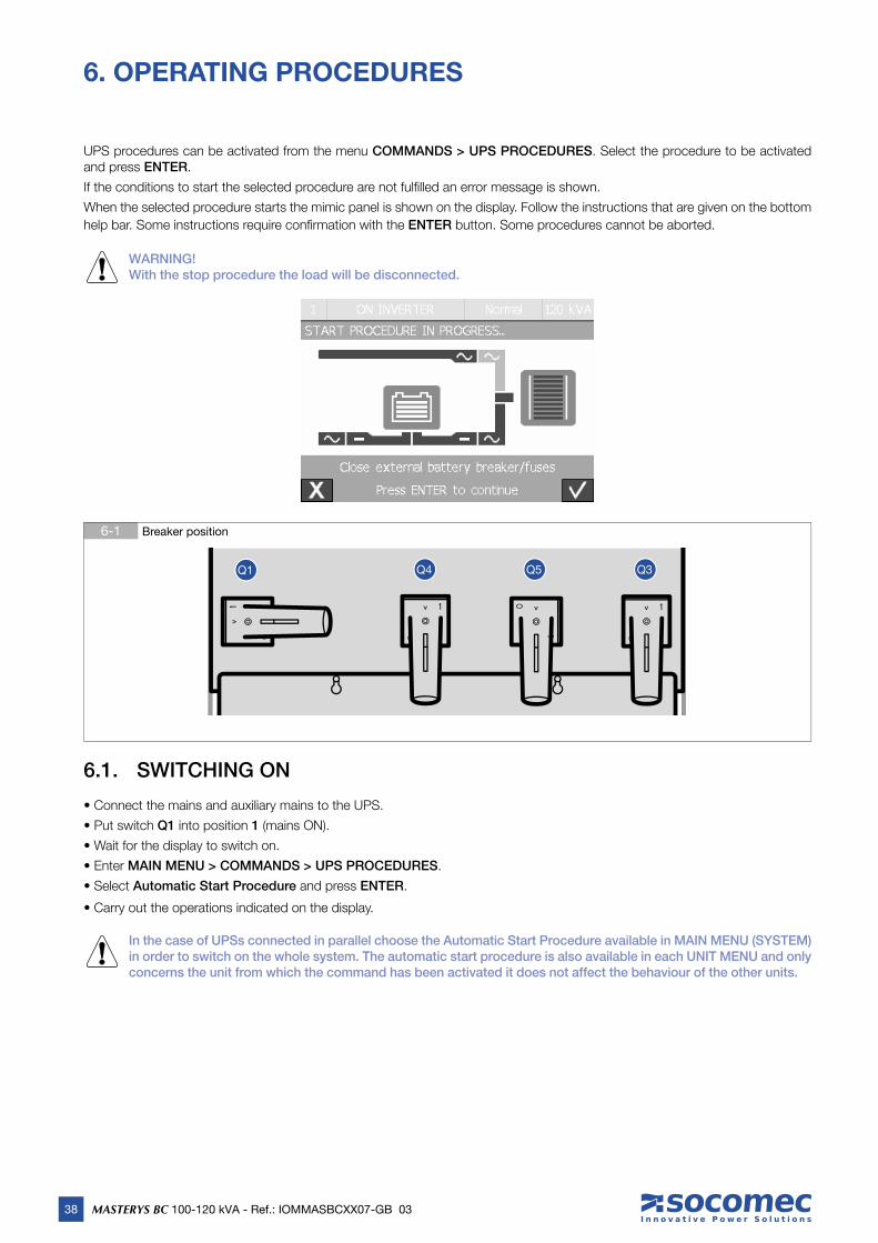
6-1 Breaker position
6. OPERATING PROCEDURES
UPS procedures can be activated from the menu COMMANDS > UPS PROCEDURES. Select the procedure to be activated and press ENTER.
If the conditions to start the selected procedure are not fulfi lled an error message is shown.
When the selected procedure starts the mimic panel is shown on the display. Follow the instructions that are given on the bottom
help bar. Some instructions require confi rmation with the ENTER button. Some procedures cannot be aborted.
WARNING! With the stop procedure the load will be disconnected.
Q1 Q4 Q5 Q3
6.1. SWITCHING ON
• Connect the mains and auxiliary mains to the UPS.
• Put switch Q1 into position 1 (mains ON).
• Wait for the display to switch on.
• Enter MAIN MENU > COMMANDS > UPS PROCEDURES.
• Select Automatic Start Procedure and press ENTER.
• Carry out the operations indicated on the display.
In the case of UPSs connected in parallel choose the Automatic Start Procedure available in MAIN MENU (SYSTEM) in order to switch on the whole system. The automatic start procedure is also available in each UNIT MENU and only concerns the unit from which the command has been activated it does not affect the behaviour of the other units.

39MASTERYS BC 100-120 kVA - Ref.: IOMMASBCXX07-GB 03
EN
GL
ISH
6. OPERATING PROCEDURES
6.2. SWITCHING ONTO MAINTENANCE BYPASS
Switching onto maintenance bypass creates a direct connection between the UPS input and output, completely excluding the equipment control element. This operation is performed in the event of standard maintenance on the equipment, so as not to remove the power supply from the load, or in the event of a serious failure while waiting for the equipment to be repaired.
• Enter menu MAIN MENU > COMMANDS > UPS PROCEDURES
• Select On Maint. Bypass Procedure and press ENTER
• Carry out the operations indicated on the display.
If there is an external manual bypass, carry out the procedure described above before activating this switch.
In the case of UPSs connected in parallel the maintenence bypass procedure is available in MAIN MENU (SYSTEM) and affects the whole system.
6.3. SWITCHING ON FROM MAINTENANCE BYPASS
• Put switch Q1 into position 1 (mains ON).
• Wait for the display to switch on.
• Enter menu MAIN MENU > COMMANDS > UPS PROCEDURES.
• Select Automatic Start Procedure and press ENTER.
• Carry out the operations indicated on the display.
If there is an external manual bypass not monitored from the UPS, or a parallel system, put the switch to position OFF to avoid overlap of mains and inverter.
6.4. EXTENDED OUT OF SERVICE
If the UPS is deactivated for some time the batteries must be recharged regularly. They should be recharged every three months.
• Connect the mains and auxiliary mains to the UPS.
• Put switch Q1 into position 1 (mains ON).
• Wait for the display to switch on.
• Close the external battery breaker/fuses.
• Put or keep switches Q3 (output) and Q5 (maintenance bypass) in position 0.
• The battery must be charged for at least ten hours.
• Once ten hours have elapsed open the external battery breaker/fuses.
• Put switch Q1 into position 0 (mains OFF).
6.5. EMERGENCY SHUTDOWN
Should it be necessary to interrupt the continuous power provided by the UPS quickly (emergency shutdown) this can be done by putting switch Q3 to position 0.
The UPS output can only be electrically disconnected by means of Q3.If the UPS is operating from the maintenance bypass (Q5 in position 1) with the mains present, the emergency shutdown does not interrupt the power supply to the load. In emergency conditions all power supplies upstream of the UPS must be disconnected.
6.6. UPS GENERAL POWER OFF
Using a button/switch connected to the ADC (Advanced Dry Contacts) card it is possible to interrupt the continuous power pro-vided by the UPS (see chapter 8).

40 MASTERYS BC 100-120 kVA - Ref.: IOMMASBCXX07-GB 03
7.1-2
7.1-1
7. CONNECTIVITY AND COMMUNICATION OPTIONS
7.1. MULTILEVEL COMMUNICATION
MASTERYS BC can manage different communication channels simultaneously. It is equipped with standard communication ports and two slots to host additional optional boards.
This gives MASTERYS BC immediate interfacing and integration fl exibility as soon as the unit is installed, with no need for trained personnel.
The table below lists the possible connections between the UPS and the external devices.
As each channel is independent, simultaneous connections can be made to satisfy the different levels of signalling and re-mote monitoring.
For UPS systems connected in parallel: all options listed in this chapter must only be installed on the UPS systems in the parallel setup configured as ICM (see chapter 2.12.1). For further information about parallel systems please refer to the relevant chapter.
345 2 1
89 7 6
RS232/485 pinout
1 Not connected
2 RX for RS232
3 TX for RS232
4 Data + for RS485
5 GND
6 Data − for RS485
7 Reserved
8 Not connected
9 +12 V
RS232 pinout
1 Reserved
2 RX for RS232
3 TX for RS232
4 Reserved
5 GND
6 Not connected
7 RTS
8 CTS
9 +12 V
Key
B Serial RS232/485 connector.
C Serial RS232 connector.
D USB connector.
B C
B
D
C

41
EN
GL
ISH
EN
GL
ISH
MASTERYS BC 100-120 kVA - Ref.: IOMMASBCXX07-GB 03
7. CONNECTIVITY AND COMMUNICATION OPTIONS
ENVIRONMENTAL confi gurationDIP1: ON - DIP2: ON
IN/OUT Description Filter level
OUT 1 General Alarm 2
OUT 2 Overheating 2
OUT 3 Overload / Loss of redundancy 2
OUT 4 External alarm In2 2
IN 1(1) ESD 1
IN 2 External alarm A39 2
IN 3(2) External alarm A40 2
POWER SAFE confi gurationDIP1: ON - DIP2: OFF
IN/OUT Description Filter level
OUT 1 General Alarm 2
OUT 2 Power safe plug 1 2
OUT 3 Power safe plug 2 2
OUT 4 Power safe plug 3 2
IN 1(1) ESD 1
IN 2 Supply from GenSet 1
IN 3(2) Management of energy consuption 1
STANDARD confi guration (default)DIP1: OFF - DIP2: OFF
IN/OUT Description Filter level
OUT 1 General alarm 2
OUT 2 Battery discharging 3
OUT 3 Battery low or imminent stop 2
OUT 4 UPS on bypass 2
IN 1(1) ESD 1
IN 2 Supply from GenSet 1
IN 3(2) Insulation controller 2
(1) If the external ESD button is not used always insert a jumper to short circuit input IN 1.
(2) The IN3 input on the ADC card with temperature sensor is for the external battery temperature sensor.
The fi lter level indicates the activation delay: 1 immediate activation (1 second minimum communication time), 2 10 s delay, 3 30 s delay.
SAFETY confi gurationDIP1: OFF - DIP2: ON
IN/OUT Description Filter level
OUT 1 General Alarm 2
OUT 2 ESD activation 1
OUT 3 Battery low or imminent stop 2
OUT 4 ESD activation 1
IN 1(1) ESD 1
IN 2 External alarm A39 2
IN 3(2) External alarm A40 2
7.2. ADC CARD
To be installed in one of the two slots available, these cards can be used to manage up to four normally closed or normally open outputs, and up to three digital inputs in confi gurable mode. If more than one ADC card is used simultaneously, the dip switch confi gurations must be different. Secure the card with the appropriate screws.
This card can be confi gured to control up to four outputs that can be set as normally closed or normally open and up to three digital in-puts. The card is inserted in one of two slots provided. Up to four operating modes can be selected using the two DIP switches 1 or 2.
• Electrical data
- Permitted Nominal current and voltage of NO or NC contacts: 2 A 250 Vac depending on the terminal used.
- Inputs are activated on loop closing.
• Connection of the generator
If your system uses a generator connect the ‘generator set ready’ no-potential contact to connector IN 2 on the optional ADC card confi gured in standard or power safe mode. This automatically extends the voltage and frequency value range when power is supplied by the generator set.
• External ESD connection
A remote emergency shutdown system (ESD) can be installed by means of the optional ADC card. Connect a normally closed zero-potential contact to terminals IN1+ and IN1- of the ADC card.
OUT2
IN3
OUT3
OUT1
IN1
IN2
OUT4
DIP2
DIP1

42 MASTERYS BC 100-120 kVA - Ref.: IOMMASBCXX07-GB 03
7. CONNECTIVITY AND COMMUNICATION OPTIONS
Intervention of the ESD input switches off the UPS output.To restore the UPS to operation:• Close the ESD contact on ‘In 1’ on the ADC board.• Send the Alarms Reset command.• Run the Automatic Start Procedure
7.3. ADC CARD WITH TEMPERATURE SENSOR
This card’s inputs/outputs have the same functions as the ADC card, with the exception of the third input (IN3).
CAUTION!Two ADC cards with temperature sensor cannot be connected simultanously.
7.4. REMOTE MIMIC PANEL
This device monitors and interacts with the UPS through a serial link RS 485 (maximum distance of 175 m) 25 m cable supplied as standard and 50 m cable available as an option (D in fi g. 9-1).
7.5. NET VISION LAN/WEB INTERFACE
NET VISION is a communication and management interface designed for business networks. The UPS behaves exactly like a networked peripheral, it can be managed remotely and allows the shutdown of network workstations.
NET VISION allows a direct interface between the UPS and LAN network avoiding dependence on the server and support SMTP, SNMP, DMCP and many other protocols. It interacts via the Web browser.
7.6. PROFIBUS INTERFACE
The externally mounted PROFIBUS adapter allows UPS models to be connected to a Profibus network.
Description of signals
Message on the mimic panel Description
General Alarm ‘General Alarm’ contact output
No alarm
C1
NO1
NC1
‘General Alarm’ active
C1
NO1
NC1
Battery Low or Imminent stop Battery low voltage and imminent shutdown contact output
Supply from GenSet Generator ready signal input
Power safe plug 1 Non privileged load 1 command output activated by overload or loss of redundancy
Power safe plug 2 Non privileged load 1 command output activated by battery discharging
Power safe plug 3 Non privileged load 1 command output activated by low battery
Management of energy consumption Input for the battery to help providing energy in the event of peak consumption
ESD activation Shutdown for ESD contact outpu
Overheating Internal overheating contact output
Overload/Loss of redundancy Overload / loss of redundancy contact output

43
EN
GL
ISH
EN
GL
ISH
MASTERYS BC 100-120 kVA - Ref.: IOMMASBCXX07-GB 03
7. CONNECTIVITY AND COMMUNICATION OPTIONS
7.7. MODBUS-TCP INTERFACE
With the slot-mounted MODBUS-TCP adapter the UPS can be monitored from remote stations using this same network protocol for functionality.
7.8. ISOLATED SERIAL PORT RS232 (DB9 CONNECTION) AND RS485 CARD
To be installed on the UPS slot.
A serial RS232 DB9 connector and an isolated RS485 connector are available on the card.
7.9. SOFTWARE OPTIONS
A large number of SW solutions can be adopted on MASTERYS BC thanks to its advanced communication facilities. These solu-tions have been specially designed for the effi cient management of power protection devices.
Visit www.socomec.com and click on DOWNLOAD then SOFTWARE to fi nd the communication software which is suitable for your requirements.

44 MASTERYS BC 100-120 kVA - Ref.: IOMMASBCXX07-GB 03
8. TROUBLESHOOTING
The alarm messages displayed enable immediate diagnosis.
Alarms are divided into two categories:
• Alarms relating to external UPS circuits: input mains, output mains, temperature and environment.
• Alarms relating to internal UPS circuits: in this case corrective action will be carried out by the After Sales Department.
The USB report makes it possible to have full information on what occurred. Refer to 5.3.11 to download it.
Note: the service code number in the HMI menu service and give it to the after sales service to help with diagnosis and troubleshooting.
8.1. SYSTEM ALARMS
A02: UPS OVERLOAD
The power required by the loads is higher than the power available.
Check the load is well balanced on the three phases by checking the measurements on the display. If required disconnect any loads that do not need uninterruptible power.
Important!The accepted overload time limit is defined in the technical specifications. When this time limit is exceeded the loads will no longer be powered by the inverter.
A06: AUXILIARY MAINS OUT OF TOLERANCE
The auxiliary mains exceeds acceptable tolerance values. Possible causes are:
• No voltage or frequency present or voltage and frequency outside acceptable values (see the technical specifi cations).
• The frequency is subjected to continuous variations (typical with power supplied from an incorrectly sized GE).
A07: INSIDE OVER TEMPERATURE
The UPS internal temperature is higher than 50 °C (please refer to the MEASUREMENTS menu on the HMI).
Check the ventilation or air conditioning system in the UPS room.
A08: MAINTENANCE BYPASS ACTIVE
The output disconnection switch Q5 is in position 1 (maintenance bypass).
The load is therefore powered directly by the mains power supply.
A17: IMPROPER USE
This alarm does not indicate a UPS malfunction or failure, but incorrect use/sizing of the system. It is activated in the event of:
• Operation for long periods at high temperatures (battery deterioration)
• High number of overloads (wrong sizing)
• Continuous battery discharging (mains not stable)
• High number of switches onto the bypass (high impulsive loads)
A22: INPUT MAINS OUT OF TOLERANCE
The input mains is not present or not suffi cient (voltage and/or frequency values incorrect with reference to the technical data. If there is no input mains outage check if any protection upstream of the UPS has tripped.
Check that the voltage applied and frequency values comply with the values set on the HMI.
A38, A39, A40, A41: EXTERNAL ALARM 1, 2, 3, 4
One of the ADC PCB inputs has been activated. Check the status of the devices connected to this PCB.
A56, A57: GENERATOR SET GENERAL ALARM / GENERATOR SET FAULT
The generator has issued an alarm. Check the GE directly.
A61: PHASE DETECTION FAULT
The phase cycle sequence is incorrect. In this case invert two phases of the input mains. For a UPS with separate auxiliary mains exchange the two phases of the auxiliary mains only.

45
EN
GL
ISH
EN
GL
ISH
MASTERYS BC 100-120 kVA - Ref.: IOMMASBCXX07-GB 03
8. TROUBLESHOOTING
8.2. UPS ALARMS
A01: BATTERY ALARM
Failure or problem on the battery circuit. Check the battery switch is closed.
A18: BLOCKING INVERTER FOR OVERLOAD
Reduce the load rate applied to the UPS and reset the alarms.
A20: WRONG CONFIGURATION
Error in the confi guration parameters. Please contact the support service.
A30: UPS STOPPED FOR OVERLOAD
Reduce the load rate applied to the UPS and reset the alarms.
A42: REMOTE SERVICE ALARM
This alarm indicates that a critical anomaly has occurred on the UPS. Where a maintenance contract with the Remote Monitoring option is in place, the procedure for analysing the UPS via remote connection will be automatically activated by your service centre provider.
A44: PERIODIC SERVICE CHECK-UP
The equipment must undergo regular inspections by the support service in order to ensure optimum performance and effi ciency. If the Scheduled Inspection signal appears ( ) on the mimic panel the equipment should be inspected by a suitably trained technician.
A51: OPTION BOARD GENERAL ALARM
Check if the optional cards are correctly inserted in the slots.
A59: BATTERY CIRCUIT OPEN
Battery switch open.
A60: FAN FAILURE
Fault in the ventilation system. Check that the air inlet at the front and the air outlet at the back of the UPS are not obstructed.
8.3. PREVENTIVE MAINTENANCE
We recommend regular specialist maintenance (annually) for the MASTERYS BC, to achieve optimum operating effi ciency and avoid equipment downtime.
It is strongly advisable to comply with any requests for preventive maintenance automatically displayed with an alert message ( ).
All operations on equipment must only be carried out by SOCOMEC personnel or authorised support personnel.
Maintenance consists of accurate functional checks on electronic and mechanical parts with replacement of parts subject to wear
if necessary (typically batteries, fans and capacitors).
8.3.1. Batteries
The condition of the external batteries is fundamental to UPS operation.
Thanks to the Expert Battery System, battery condition information is processed in real time and recharging and discharging procedures are selected automatically in order to optimise battery lifetime expectancy and offer maximum performance.
Furthermore, during the operating lifetime of the battery, MASTERYS BC stores statistics on battery conditions of use for analysis.
Since the expected lifetime of batteries is very much dependent on operating conditions (number of charging and discharging
cycles, load rate, temperature), a regular inspection by authorised personnel is recommended.
When replacing the batteries use the same type and configuration by placing them in the appropriate containers so as to avoid the risk of acid leakage.Used batteries must be disposed of at authorised recycling and disposal centres.Do not open the plastic cover of the batteries as they contain harmful substances.
46 MASTERYS BC 100-120 kVA - Ref.: IOMMASBCXX07-GB 03
8. TROUBLESHOOTING
8.3.2. Fans
The lifetime of fans used to cool the power parts is dependent on usage and environmental conditions (temperature, dust).
Preventive replacement by an authorised technician is recommended within four years (in normal operating conditions).
Fans must be replaced by SOCOMEC technicians when required.
8.3.3. Capacitors
The equipment houses electrolytic capacitors (used in the rectifi er and inverter section) and fi ltering capacitors (used in the output section), whose lifetime is dependent on usage and environmental conditions.
The average expected lifetime of these components is shown below:
• Electrolytic capacitors: 5 years;
• Filtering capacitors: 7 years.
The actual condition of components is verifi ed during preventive maintenance.
47MASTERYS BC 100-120 kVA - Ref.: IOMMASBCXX07-GB 03
EN
GL
ISH
9. ELECTRICAL OPTIONS
9.1. INSULATION CONTROLLER
This device continually checks transformer insulation, displaying an alarm message on the mimic panel.
9.2. EXTERNAL MAINTENANCE BYPASS
This device will electrically exclude and isolate the UPS (e.g. for maintenance operations) without interrupting the power supplied to the load.
9.3. ACS PCB
Synchronises UPS output with an external power source (another UPS, even of a different brand, generator or transformer).
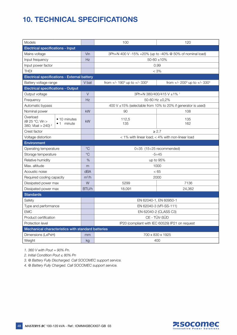
48 MASTERYS BC 100-120 kVA - Ref.: IOMMASBCXX07-GB 03
10. TECHNICAL SPECIFICATIONS
1. 360 V with Pout = 90% Pn.
2. Initial Condition Pout ≤ 80% Pn
3. @ Battery Fully Discharged. Call SOCOMEC support service.
4. @ Battery Fully Charged. Call SOCOMEC support service.
Models 100 120
Electrical specifications - Input
Mains voltage Vin 3Ph+N 400 V -15% +20% (up to -40% @ 50% of nominal load)
Input frequency Hz 50-60 ±10%
Input power factor 0.99
THDI < 3%
Electrical specifications - External battery
Battery voltage range V bat from +/- 1903 up to +/- 3304 from +/- 2003 up to +/- 3304
Electrical specifications - Output
Output voltage V 3Ph+N 380/400/415 V ±1% 1
Frequency Hz 50-60 Hz ±0,2%
Automatic bypass 400 V ±15% (selectable from 10% to 20% if generator is used)
Nominal power kW 90 108
Overload(@ 25 °C; Vin > 380; Vbat > 240) 2
• 10 minutes• 1 minute
kW112,5135
135162
Crest factor ≥ 2.7
Voltage distortion < 1% with linear load; < 4% with non-linear load
Environment
Operating temperature °C 0÷35 (15÷25 recommended)
Storage temperature °C -5÷45
Relative humidity % up to 95%
Max. altitude m 1000
Acoustic noise dBA < 65
Required cooling capacity m3/h 2000
Dissipated power max W 5299 7136
Dissipated power max BTU/h 18,091 24,362
Standards
Safety EN 62040-1, EN 60950-1
Type and performance EN 62040-3 (VFI-SS-111)
EMC EN 62040-2 (CLASS C3)
Product certifi cation CE - TÜV-SÜD
Protection level IP20 (compliant with IEC 60529) IP21 on request
Mechanical characteristics with standard batteries
Dimensions (LxPxH) mm 700 x 830 x 1925
Weight kg 400


www.socomec.com
VALID FOR FRANCE VALID FOR ITALY
ISO 9001FM 28237
ISO14001EMS 553476
YOUR DISTRIBUTOR HEAD OFFICE
SOCOMEC GROUPS.A. SOCOMEC capital 10 951 300 € R.C.S. Strasbourg B 548 500 149 B.P. 60010 - 1, rue de Westhouse F-67235 Benfeld Cedex - FRANCE
SALES, MARKETING AND SERVICE MANAGEMENT
SOCOMEC Paris95, rue Pierre Grange F-94132 Fontenay-sous-Bois Cedex FRANCE Tel. +33 (0)1 45 14 63 90 Fax +33 (0)1 48 77 31 12 [email protected]
Socomec worldwide
IN WESTERN EUROPE
BELGIUMB - 1190 Bruxelles Tel. +32 (0)2 340 02 34 [email protected]
FRANCEF - 94132 Fontenay-sous-Bois Cedex Tel. +33 (0)1 45 14 63 90 [email protected]
GERMANYD - 68309 Mannheim Tel. +49 (0) 621 71 68 40 [email protected]
ITALY20098 San Giuliano Milanese (MI) Tel. +39 02 98 242 942 [email protected]
PORTUGAL 2640-486 Mafra Tel. +351 261 812 599 [email protected]
SPAINE - 08329 Teià (Barcelona) Tel. +34 935 407 575 [email protected]
THE NETHERLANDSNL - 3991 CD Houten Tel. +31 (0)30 760 0911 [email protected]
UNITED KINGDOMCirencester - GL7 5XL Tel. +44 (0)1285 863300 [email protected]
OTHER COUNTRIESTel. +34 935 407 575 [email protected]
IN EASTERN EUROPE, MIDDLE EAST, AFRICA
UNITED ARAB EMIRATES371355 Dubai airport free zone Dubai (United Arab Emirates) Tel.: +971 (0) 4 29 98 441 [email protected]
POLAND01-625 Warszawa Tel. +48 22 825 73 60 [email protected]
ROMANIA023383 Bucharest Tel. +40 21 319 36 88 ( 89, 81, 82) [email protected]
RUSSIA125167 - Moscow Tel. +7 495 775 19 85 [email protected]
SLOVENIASI - 1000 Ljubljana Tel. +386 1 5807 860 [email protected]
TURKEY34357 Istanbul Tel. +90 (0) 216 540 71 20 [email protected]
OTHER COUNTRIESTel. +39 0444 598 611 [email protected]
IN ASIA PACIFIC
AUSTRALIAMacquarie Park NSW 2113 Tel. +61 2 9325 3900 [email protected]
CHINAChaoyang, Beijing 100016 P.R., China Tel. +86 10 59756108 [email protected]
INDIAGuindy, Chennai – 600 032 Tel. +91 44 3921 5400 [email protected]
MALAYSIA47301 Petaling Jaya.- Selangor, Malaysia Tel. +603 7804 0850 [email protected]
SINGAPORE Singapore 408723 Tel. +65 6506 7600 [email protected]
THAILANDChatujak Bangkok 10900 Tel. +66 2 941-1644-7 [email protected]
VIETNAMHo Chi Minh City Tel. +84 8 3559 1220 [email protected]
ASIA PACIFIC HEAD OFFICETel. +65 6506 [email protected]
IN AMERICA
LATIN AMERICAN COUNTRIESTel. +34 935 407 575 [email protected]
*IOMMASBCXX07-GB 03*IOMMASBCXX07-GB 03 10.2013
Related Documents