Faculty of Science and Technology MASTER’S THESIS Study program/ Specialization: Structural engineering and Material science Spring semester, 2012 Open / Restricted access Writer: Atle Aasgaard ………………………………………… (W riter’s signature) Faculty supervisor: Rolf A. Jakobsen, University of Stavanger S. A. Sudath C. Siriwardane, University of Stavanger External supervisor(s): Johan Christian Brun, Aker Solutions Title of thesis: Design and analysis of skywalk in aluminium Credits (ECTS): 30 Key words: Aluminium Skywalk Structural analysis STAAD Pro v8i Pages: IX + 43 +Attachments/Other: 91 Stavanger, 13.06.2012

Welcome message from author
This document is posted to help you gain knowledge. Please leave a comment to let me know what you think about it! Share it to your friends and learn new things together.
Transcript
Faculty of Science and Technology
MASTER’S THESIS
Study program/ Specialization: Structural engineering and Material science
Spring semester, 2012
Open / Restricted access
Writer: Atle Aasgaard …………………………………………
(Writer’s signature)
Faculty supervisor: Rolf A. Jakobsen, University of Stavanger
S. A. Sudath C. Siriwardane, University of Stavanger External supervisor(s): Johan Christian Brun, Aker Solutions
Title of thesis: Design and analysis of skywalk in aluminium
Credits (ECTS): 30
Key words: Aluminium Skywalk Structural analysis STAAD Pro v8i
Pages: IX + 43 +Attachments/Other: 91
Stavanger, 13.06.2012
Atle Aasgaard Design and analysis of skywalk in aluminium Page ii
ABSTRACT
During 2012 Aker Solutions will build new buildings in Stavanger.
The buildings will be placed in Jåttåvågen and be completed towards the end of
2012. Two of the buildings will be linked together by a skywalk at the second floor.
The alternatives have been to design a skywalk made of steel or use aluminium to
utilize the positive characteristics of aluminium. Aluminium has been used.
The main focus of this thesis is to design and analyze a skywalk between two
buildings and get an understanding of aluminium as a structural material.
The skywalk is modelled and analyzed using STAAD Pro v8i and the maximum
utilization ratios for the ultimate limit state are listed below:
Beam members: 0.707
Local check joints: 0.956
The skywalk has sufficient capacity in the ultimate limit state.
Aluminium has a low modulus of elasticity and instability and the feeling of instability
may be a problem. The skywalk is checked for displacement in serviceability limit
state.
Maximum deflection: 20.320 mm
Neither the horizontal nor the vertical displacement will make the skywalk feel
instable. However, the displacement of the glass facades may be too high and
should be further checked.
Aluminium has a great future as a structural material, especially when weight or
corrosion is a problem.
For this skywalk neither weight nor corrosion is a problem and the method of
jointing the structure with casted joints will be expensive.
It is fully possible to design the skywalk in aluminium but steel would be a more
natural choice and probably less expensive.
Atle Aasgaard Design and analysis of skywalk in aluminium Page iii
ACKNOWLEDGEMENT
This report is the result of a Master’s thesis from the study program structural
engineering and material science at the University of Stavanger. This thesis is
completed during the spring semester 2012 for Aker Solutions, Stavanger, in
collaboration with the University of Stavanger.
This report has been carried out under the supervision of Rolf A. Jakobsen and
S. A. Sudath C. Siriwardane at the University at Stavanger.
I would like to express my gratitude to my principal faculty supervisor Rolf A.
Jakobsen for interesting conversations and good help throughout this thesis.
I would like to thank Aker Solutions and my external supervisor Johan Christian Brun
for good help and support throughout
I would also like to thank internal supervisor S. A. Sudath C. Siriwardane.
Stavanger, 13. June 2012
___________________
Atle Aasgaard
Atle Aasgaard Design and analysis of skywalk in aluminium Page iv
TABLE OF CONTENTS
ABSTRACT ............................................................................................................... II
ACKNOWLEDGEMENT ............................................................................................ III
TABLE OF CONTENTS .............................................................................................. IV
LIST OF FIGURES ................................................................................................... VI
LIST OF TABLES..................................................................................................... VII
ABBREVIATIONS AND DEFINITIONS ................................................................... VIII
SYMBOLS ................................................................................................................ IX
1. INTRODUCTION................................................................................................ 1
1.1 REPORT OVERVIEW ........................................................................................ 1
1.2 SCOPE OF REPORT .......................................................................................... 1
1.3 LIMITATIONS ................................................................................................. 1
2. ALUMINIUM ..................................................................................................... 2
2.1 INTRODUCTION .............................................................................................. 2
2.2 WHEN TO CHOOSE ALUMINIUM ........................................................................ 2
2.3 MANUFACTURE ............................................................................................... 3
2.4 ALUMINIUM PRODUCTS ................................................................................... 5
2.5 ELEMENT FABRICATION ................................................................................... 5
2.6 PROPERTIES .................................................................................................. 6
2.7 COMPARISON WITH STEEL .............................................................................. 8
2.8 ALUMINIUM ALLOYS ...................................................................................... 10
2.9 JOINTING ALUMINIUM ................................................................................... 13
2.10 STRENGTH VARIATION WITH TEMPERATURE .................................................... 14
2.11 HEAT AFFECTED ZONE .................................................................................. 16
2.12 CORROSION ................................................................................................ 16
3. DESIGN AND GEOMETRY ................................................................................ 18
3.1 GENERAL ..................................................................................................... 18
3.2 GEOMETRY AND PROPERTIES ......................................................................... 20
3.3 SUPPORT POINTS ......................................................................................... 20
3.4 LOCAL JOINT DESIGN ................................................................................... 21
3.5 LIFTING ARRANGEMENT ................................................................................ 22
3.6 FACADES ..................................................................................................... 22
4. LOADS AND LOADING CONDITIONS ............................................................... 24
4.1 LOAD CASES ................................................................................................ 24
4.2 LIMIT STATES .............................................................................................. 26
5. DESIGN INPUT FOR MODEL ............................................................................ 27
5.1 GENERAL ..................................................................................................... 27
5.2 UNITS ......................................................................................................... 27
5.3 GLOBAL COORDINATE SYSTEM....................................................................... 27
5.4 LOCAL COORDINATE SYSTEM ......................................................................... 27
5.5 THE MODEL.................................................................................................. 28
5.6 BOUNDARY CONDITIONS ............................................................................... 29
5.7 CODE CHECK ............................................................................................... 29

Atle Aasgaard Design and analysis of skywalk in aluminium Page v
5.8 MATERIAL .................................................................................................... 30
5.9 CALCULATION OF FORCES AND BENDING MOMENTS ........................................ 31
5.10 LOCAL JOINT CHECK ..................................................................................... 34
6. ANALYSIS RESULTS ........................................................................................ 36
6.1 BEAM CHECK ............................................................................................... 36
6.2 LOCAL CHECK JOINTS ................................................................................... 36
6.3 DEFLECTION ................................................................................................ 37
6.4 SUPPORT REACTION ..................................................................................... 38
7. CONCLUSION .................................................................................................. 40
REFERENCES .......................................................................................................... 42
APPENDIX I – LOADS
APPENDIX II – GLASS FACADE DIMENSIONING
APPENDIX III – STAAD PRO V8I ANALYSIS BEAMS
APPENDIX IV – STAAD PRO V8I ANALYSIS JOINTS
APPENDIX V – LOCAL CHECK CAST JOINTS
APPENDIX VI – LOCAL CHECK BOLTED CONNECTIONS
APPENDIX VII - DRAWINGS

Atle Aasgaard Design and analysis of skywalk in aluminium Page vi
LIST OF FIGURES
Figure 2-1: Analysis of earth's crust (Budd, 1999) ........................................................... 2
Figure 2-2: Aluminium production (Müller, 2011) ............................................................ 3
Figure 2-3: The Bayer process (Müller, 2011) ................................................................. 4
Figure 2-4: The Hall-Héroult process (Müller, 2011) ........................................................ 4
Figure 2-5: Stress-strain curves for aluminium and steel .................................................. 7
Figure 2-6: Stress-strain curves for various aluminium alloys (European aluminium
assosiation, Matter, 2001-2010) ................................................................................... 7
Figure 2-7: Example for different geometry (Jakobsen, n.d.) ............................................ 8
Figure 2-8: Comparison for fatigue (Jakobsen, n.d.) ........................................................ 9
Figure 2-9: Comparison for shock absorbance (Jakobsen, n.d.) ......................................... 9
Figure 2-10: Comparison for corrosion (Jakobsen, n.d.) ................................................. 10
Figure 2-11: Variation of tensile stress (fu) with temperature T for various alloys (Dwight,
1999) ...................................................................................................................... 15
Figure 2-12: Variation of proof stress (fo) and tensile strength (fu) with temperature, for the
6082-T6 alloy (Dwight, 1999) ..................................................................................... 15
Figure 2-13: HAZ softening at aluminium welds (Dwight, 1999) ...................................... 16
Figure 3-1: Design of skywalk ..................................................................................... 18
Figure 3-2: Design of skywalk 2 .................................................................................. 19
Figure 3-3: Illustration of the inside of the skywalk ....................................................... 19
Figure 3-4: Model of bearing structure ......................................................................... 20
Figure 3-5: Support points ......................................................................................... 20
Figure 3-6: Illustration of Support point ....................................................................... 21
Figure 3-7: Illustration of a typical joint ....................................................................... 21
Figure 3-8: Glass facade system (Sapa building system AB, 2012) .................................. 22
Figure 3-9: Vertical profiles (Sapa Building system AB, 2012) ......................................... 23
Figure 4-1: Load distribution of LC2 ............................................................................. 24
Figure 4-2: Load distribution of LC3-LC6 ...................................................................... 25
Figure 4-3: Load distribution of LC7 ............................................................................. 25
Figure 4-4: Load distribution LC8 ................................................................................ 26
Figure 5-1: Cartesian (rectangular) coordinate system ................................................... 27
Figure 5-2: Local coordinate system ............................................................................ 28
Figure 5-3: Analytical model of the skywalk .................................................................. 28
Figure 5-4: Geometry of boundary condition ................................................................. 29
Figure 5-5: Geometry of tube section .......................................................................... 33
Figure 5-6: Joints to be checked ................................................................................. 34
Figure 6-1: Four middle nodes .................................................................................... 37
Figure 6-2: Support nodes.......................................................................................... 38
Figure 7-1: Deflection ................................................................................................ 40
Atle Aasgaard Design and analysis of skywalk in aluminium Page vii
LIST OF TABLES
Table 2-1: Properties of pure aluminium (Müller, 2011) ................................................... 6
Table 2-2: Comparison between aluminium and steel (Jakobsen, n.d.) .............................. 8
Table 2-3: Comparison for equal geometry (Jakobsen, n.d.) ............................................. 8
Table 2-4: Comparison for different geometry (Jakobsen, n.d.) ......................................... 9
Table 2-5: Numerical wrought alloy designation system ................................................. 10
Table 2-6: Numerical cast alloy designation system ....................................................... 11
Table 2-7: Basic temper designation ............................................................................ 12
Table 2-8: Temper designation system to current standards ........................................... 13
Table 2-9: Characteristic values of 0.2% proof strength f0 and ultimate tensile strength fu for
unwelded and for HAZ for alloy EN-AW 6082 ................................................................ 16
Table 2-10: Electrochemical series of metals ................................................................ 17
Table 4-1: Load cases ................................................................................................ 24
Table 4-2: Limit states ............................................................................................... 26
Table 5-1: Characteristic values for profiles .................................................................. 30
Table 5-2: Characteristic values for joints .................................................................... 31
Table 5-3: Characteristic values for bolts ..................................................................... 31
Table 5-4: Stress calculation at selected points ............................................................. 33
Table 6-1: Most utilized beams ................................................................................... 36
Table 6-2: Utilization of UFcreening for checked joints ....................................................... 36
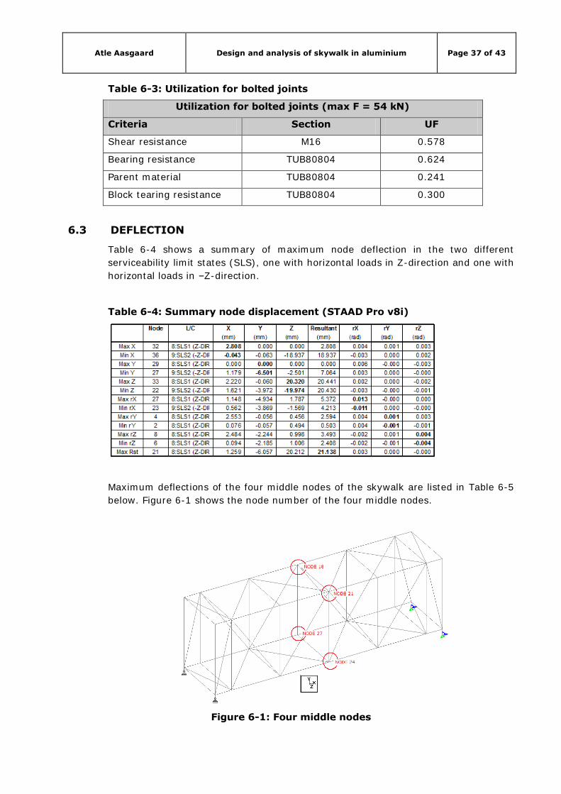
Table 6-3: Utilization for bolted joints .......................................................................... 37
Table 6-4: Summary node displacement (STAAD Pro v8i)............................................... 37
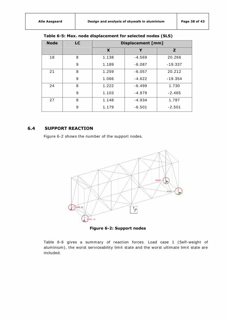
Table 6-5: Max. node displacement for selected nodes (SLS) .......................................... 38
Table 6-6: Summary reaction forces ............................................................................ 39
Atle Aasgaard Design and analysis of skywalk in aluminium Page viii
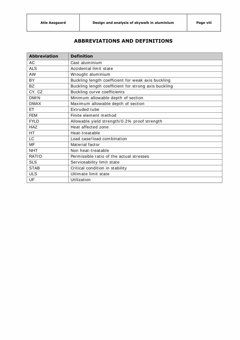
ABBREVIATIONS AND DEFINITIONS
Abbreviation Definition
AC Cast aluminium
ALS Accidental limit state
AW Wrought aluminium
BY Buckling length coefficient for weak axis buckling
BZ Buckling length coefficient for strong axis buckling
CY, CZ Buckling curve coefficients
DMIN Minimum allowable depth of section
DMAX Maximum allowable depth of section
ET Extruded tube
FEM Finite element method
FYLD Allowable yield strength/0.2% proof strength
HAZ Heat affected zone
HT Heat-treatable
LC Load case/load combination
MF Material factor
NHT Non heat-treatable
RATIO Permissible ratio of the actual stresses
SLS Serviceability limit state
STAB Critical condition in stability
ULS Ultimate limit state
UF Utilization

Atle Aasgaard Design and analysis of skywalk in aluminium Page ix
SYMBOLS
Symbol Definition
A Min. elongation
A Cross section area
Anet Net section area
Ant Net area subjected to tension
Anv Net area subjected to shear
d Diameter for bolt
d0 Hole diameter
E Modulus of elasticity
fo Characteristic value of 0.2% proof strength
fo,haz 0.2% proof strength in heat affected zone, HAZ
fu Ultimate tensile strength
fu,haz Ultimate tensile strength in heat affected zone, HAZ
Fb,Rd Design bearing resistance per bolt
Fv,Ed Design shear force per bolt (ULS)
Fv,Rd Design shear resistance per bolt
G Shear modulus
Nnet,Rd Design resistance of section at bolt holes
Veff,1,Rd Design block tearing resistance for concentric loading
γM1, γM2 Partial safety factor/material factor
ν Poisson’s ratio
α Coefficient of thermal expansion
ρ Density
e1, e2 Edge distances
p1 Spacing between bolt holes
Atle Aasgaard Design and analysis of skywalk in aluminium Page 1 of 43
1. INTRODUCTION
1.1 REPORT OVERVIEW
This report is divided into seven chapters. The first part is a theoretical part giving
an introduction to aluminium as a structural material. The second part contains a
design part and consists of design and geometry of the skywalk. The third part is an
analytical part where the STAAD Pro v8i analysis and its input are presented. The
results of the STAAD Pro v8i analysis are presented in chapter 6 and conclusion in
chapter 7.
1.2 SCOPE OF REPORT
The scope of this master’s thesis is to model and analyse a skywalk, using STAAD
Pro v8i, for the new buildings to Aker Solutions in Jåttåvågen. The buildings will be
completed towards the end of 2012. The skywalk should be analysed using
aluminium and a big part of this thesis is to look at the positive and negative
characteristics of aluminium as a structural material. The skywalk should be
modelled without welds.
1.3 LIMITATIONS
Due to the very small likelihood of an earthquake in Stavanger actions caused by
earthquakes have been disregarded in this thesis.
Fatigue has been disregarded in this thesis.
The skywalk is not designed to withstand hazards due to fire.
The structure is depending on static loads only.

Atle Aasgaard Design and analysis of skywalk in aluminium Page 2 of 43
2. ALUMINIUM
2.1 INTRODUCTION
Aluminium is a metallic element having the chemical symbol Al, with the atomic
number 13 and atomic weight 27. The nucleus of the atom contains 13 protons and
14 neutrons. Aluminium is found primarily as bauxite ore and is the third most
common element in the earth’s crust, after oxygen and silicon. It makes up 8% of
the crust’s total mass and is the most abundant metal, see Figure 2-1.
Figure 2-1: Analysis of earth's crust (Budd, 1999)
Norway is among the world’s largest producers of aluminium. Norway’s unique
position as a producer of aluminium is due to the supply of electrical energy. Under
normal circumstances 90% of the production is exported.
The fact that Norwegian aluminium is produced using environmentally friendly
hydropower makes the CO2 emissions per tonne of Al only one tenth of the
emissions from a smelter operated with electricity from a coal power plant, which is
common in for example China.
2.2 WHEN TO CHOOSE ALUMINIUM
Lightweight: aluminium is light. It weights about one third of steel. This is an
important factor if the self-weight is a concern.
Corrosion resistance: Aluminium forms its own protective layer against corrosion
when exposed to air. Aluminium has ability for self-healing if the protective layer is
damaged. Aluminium can be used unpainted.
Fabrication: Aluminium is soft, and it can easily be fabricated into various forms and
shapes.
Heat conductivity: Aluminium is approximately three times as thermally conductive
as steel.
Atle Aasgaard Design and analysis of skywalk in aluminium Page 3 of 43
Low temperature performance: Aluminium does not become brittle at low
temperatures as steel do. The mechanical properties of aluminium improve as the
temperature goes down.
Recyclability: Aluminium can easily be recycled and reprocessed.
Reflectivity: Aluminium is highly reflective of light, heat and electric waves.
Non-toxic: Aluminium is non-toxic and odourless.
Non-magnetic: Aluminium is non-magnetic
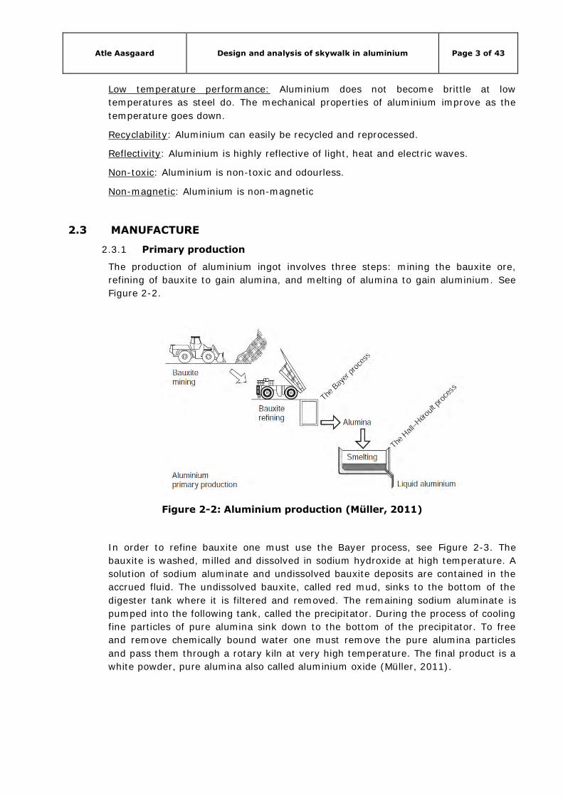
2.3 MANUFACTURE
2.3.1 Primary production
The production of aluminium ingot involves three steps: mining the bauxite ore,
refining of bauxite to gain alumina, and melting of alumina to gain aluminium. See
Figure 2-2.
Figure 2-2: Aluminium production (Müller, 2011)
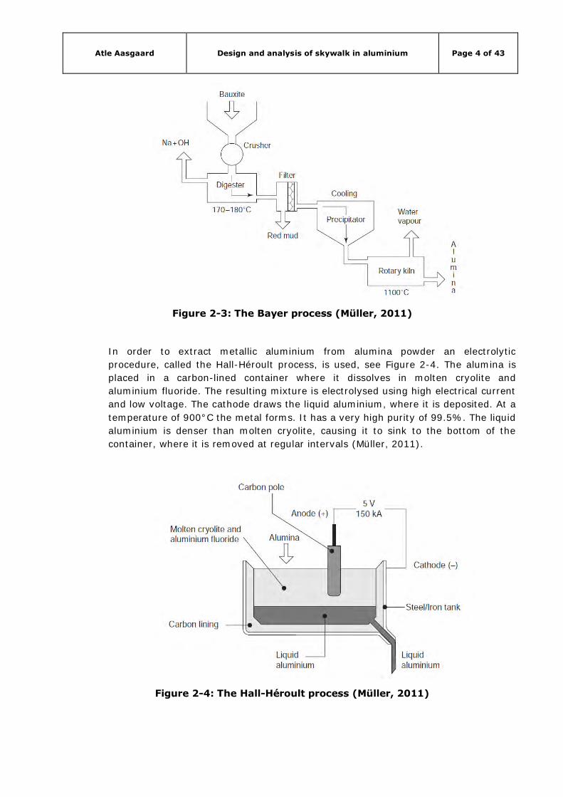
In order to refine bauxite one must use the Bayer process, see Figure 2-3. The
bauxite is washed, milled and dissolved in sodium hydroxide at high temperature. A
solution of sodium aluminate and undissolved bauxite deposits are contained in the
accrued fluid. The undissolved bauxite, called red mud, sinks to the bottom of the
digester tank where it is filtered and removed. The remaining sodium aluminate is
pumped into the following tank, called the precipitator. During the process of cooling
fine particles of pure alumina sink down to the bottom of the precipitator. To free
and remove chemically bound water one must remove the pure alumina particles
and pass them through a rotary kiln at very high temperature. The final product is a
white powder, pure alumina also called aluminium oxide (Müller, 2011).
Atle Aasgaard Design and analysis of skywalk in aluminium Page 4 of 43
Figure 2-3: The Bayer process (Müller, 2011)
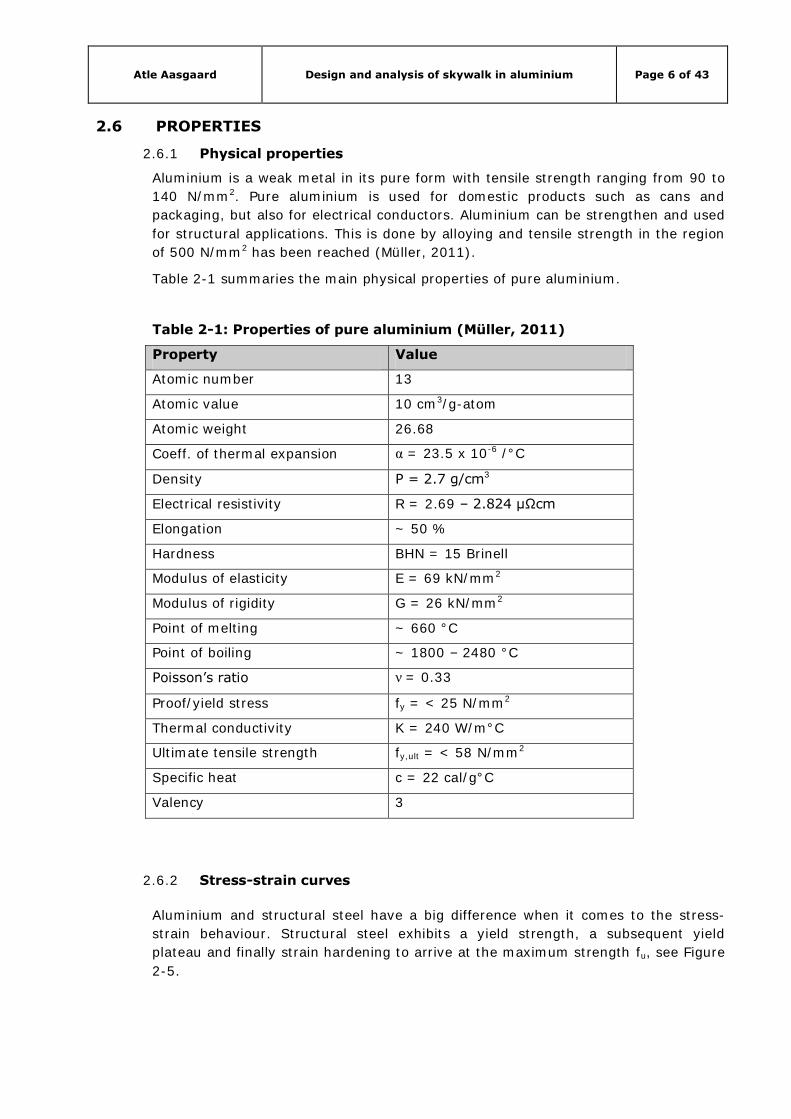
In order to extract metallic aluminium from alumina powder an electrolytic
procedure, called the Hall-Héroult process, is used, see Figure 2-4. The alumina is
placed in a carbon-lined container where it dissolves in molten cryolite and
aluminium fluoride. The resulting mixture is electrolysed using high electrical current
and low voltage. The cathode draws the liquid aluminium, where it is deposited. At a
temperature of 900°C the metal forms. It has a very high purity of 99.5%. The liquid
aluminium is denser than molten cryolite, causing it to sink to the bottom of the
container, where it is removed at regular intervals (Müller, 2011).
Figure 2-4: The Hall-Héroult process (Müller, 2011)

Atle Aasgaard Design and analysis of skywalk in aluminium Page 5 of 43
2.3.2 Secondary production, recycling
Aluminium can be recycled repeatedly, as the reprocessing does no harm to the
metal or its structure. When it has arrived at the recycling plant, the scrap
aluminium will be checked and sorted to determine its composition and value. Some
of the scrap aluminium must be processed further to remove coatings and other
contaminations. The “clean” scrap aluminium is melted in furnaces. Processing of the
molten aluminium is the same method as for primary processing.
The energy required to recycle scrap aluminium to aluminium metal is only 5% of
the energy used to produce the metal in primary production (Müller, 2011).
2.4 ALUMINIUM PRODUCTS
Processing of aluminium and its alloys is done in various ways to produce aluminium
products for private, commercial and industrial use. The manufacturing process for
products of aluminium includes both modern methods and traditional processes,
such as milling and extruding in the former case, and forging and casting in the
latter. Forging and castings products are still seeing wide use, especially for
architectural and office or home use, whilst milling products and extruded sections
are more often used for structural applications. Milled and extruded, but also drawn
products used for structural application are subdivided into flat products, extruded
products and tube products. Their main characteristics are the process of
manufacture and heating used for the manufacture of specific products (Müller,
2011).
2.5 ELEMENT FABRICATION
Aluminium goods are usually delivered as semi-finished products, most of them as
sheet, plate, extrusions and tube products. These products are subsequently further
shaped and fabricated to create the desired shapes or elements utilising a broad
range of fabrication processes. All fabrication processes used in steel fabrication can,
as a general rule, be used with aluminium goods. The main difference lies in that the
softer aluminium allows for a quicker and cheaper fabrication as compared to the
fabrication of steel. The processes that are typically used are cutting, sawing,
drilling, punching, bending, machining and welding (Müller, 2011).
Atle Aasgaard Design and analysis of skywalk in aluminium Page 6 of 43
2.6 PROPERTIES
2.6.1 Physical properties
Aluminium is a weak metal in its pure form with tensile strength ranging from 90 to
140 N/mm2. Pure aluminium is used for domestic products such as cans and
packaging, but also for electrical conductors. Aluminium can be strengthen and used
for structural applications. This is done by alloying and tensile strength in the region
of 500 N/mm2 has been reached (Müller, 2011).
Table 2-1 summaries the main physical properties of pure aluminium.
Table 2-1: Properties of pure aluminium (Müller, 2011)
Property Value
Atomic number 13
Atomic value 10 cm3/g-atom
Atomic weight 26.68
Coeff. of thermal expansion α = 23.5 x 10⁻⁶ /°C
Density Ρ = 2.7 g/cm3
Electrical resistivity R = 2.69 – 2.824 μΩcm
Elongation ~ 50 %
Hardness BHN = 15 Brinell
Modulus of elasticity E = 69 kN/mm2
Modulus of rigidity G = 26 kN/mm2
Point of melting ~ 660 °C
Point of boiling ~ 1800 – 2480 °C
Poisson’s ratio ν = 0.33
Proof/yield stress fy = < 25 N/mm2
Thermal conductivity K = 240 W/m°C
Ultimate tensile strength fy,ult = < 58 N/mm2
Specific heat c = 22 cal/g°C
Valency 3
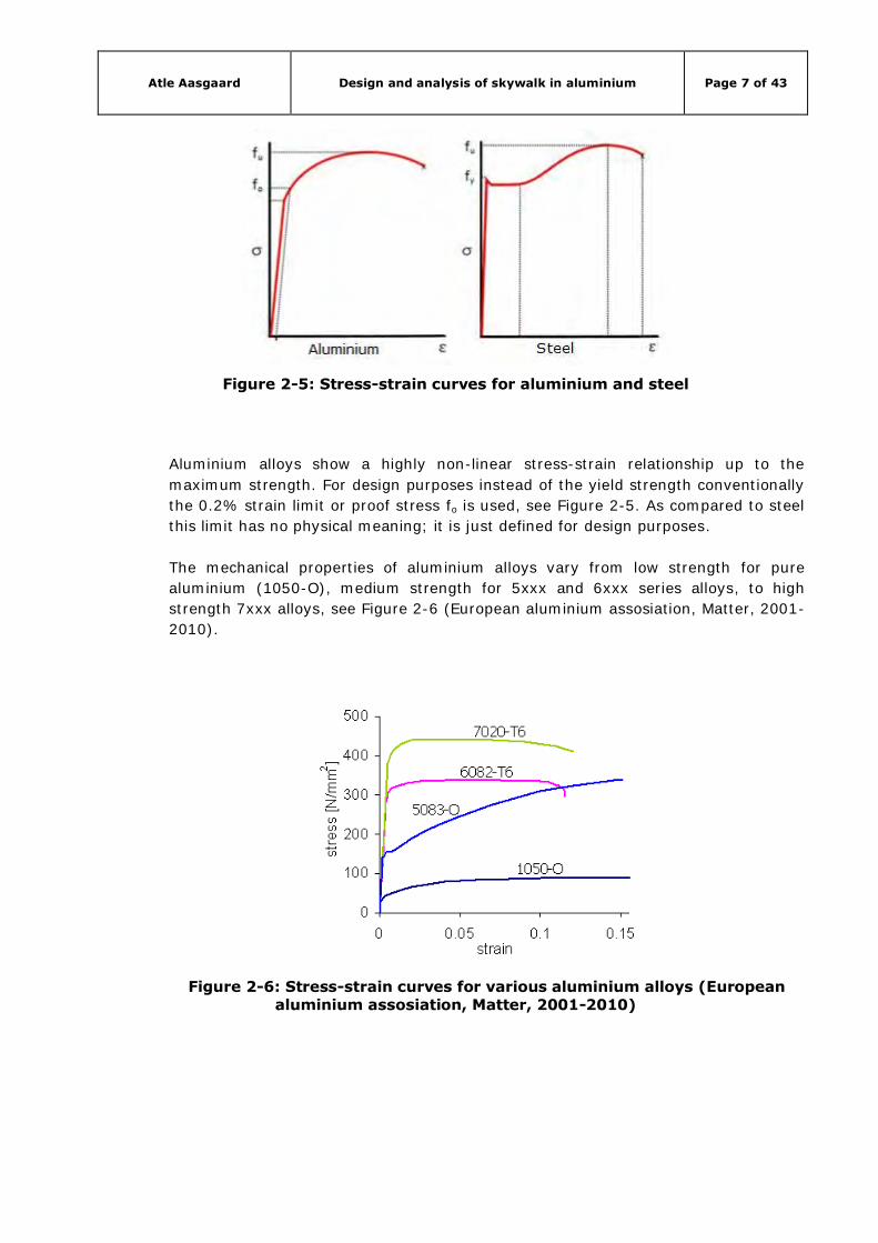
2.6.2 Stress-strain curves
Aluminium and structural steel have a big difference when it comes to the stress-
strain behaviour. Structural steel exhibits a yield strength, a subsequent yield
plateau and finally strain hardening to arrive at the maximum strength fu, see Figure 2-5.
Atle Aasgaard Design and analysis of skywalk in aluminium Page 7 of 43
Figure 2-5: Stress-strain curves for aluminium and steel
Aluminium alloys show a highly non-linear stress-strain relationship up to the
maximum strength. For design purposes instead of the yield strength conventionally
the 0.2% strain limit or proof stress fo is used, see Figure 2-5. As compared to steel
this limit has no physical meaning; it is just defined for design purposes.
The mechanical properties of aluminium alloys vary from low strength for pure
aluminium (1050-O), medium strength for 5xxx and 6xxx series alloys, to high
strength 7xxx alloys, see Figure 2-6 (European aluminium assosiation, Matter, 2001-
2010).
Figure 2-6: Stress-strain curves for various aluminium alloys (European aluminium assosiation, Matter, 2001-2010)
Atle Aasgaard Design and analysis of skywalk in aluminium Page 8 of 43
2.7 COMPARISON WITH STEEL
Below is a comparison between aluminium (AlMgSi1) and steel (St 52) for some
chosen properties, see Table 2-2. Stress-strain curves are compared above.
Table 2-2: Comparison between aluminium and steel (Jakobsen, n.d.)
Property AlMgSi1 St 52 AlMgSi1/St 52
Density 2.7 g/cm3 7.8 g/cm3 ~ 1:3
Modulus of elasticity 70 kN/mm2 208 kN/mm2
Ultimate stress 310 N/mm2 520 N/mm2 ~ 1:1.7
Yield stress 270 N/mm2 340 N/mm2 ~ 1:1.3
Melting point 660°C 1510°C
Boiling point 1800-2480°C 2750°C
Thermal expansion coeff. 23.5*10-6/°C 12*10-6/°C ~ 1:1.05
Thermal conductivity 225 W/m°C 50 W/m°C ~ 1:1.02
Heat capacity 0.92 kJ/kg°C 0.52 kJ/kg°C ~ 1:1.17
“For cases where yield stresses are dimensioning the weight ratio steel/aluminium is
2/1.
For unloaded components the weight ratio steel/aluminium is 3/1” (Jakobsen, n.d.).
Table 2-3 shows the comparison between steel and aluminium for equal beam
geometry.
Table 2-3: Comparison for equal geometry (Jakobsen, n.d.)
Steel Aluminium
Weight 1 1/3
Deformation 1 3
Beam height 1 1
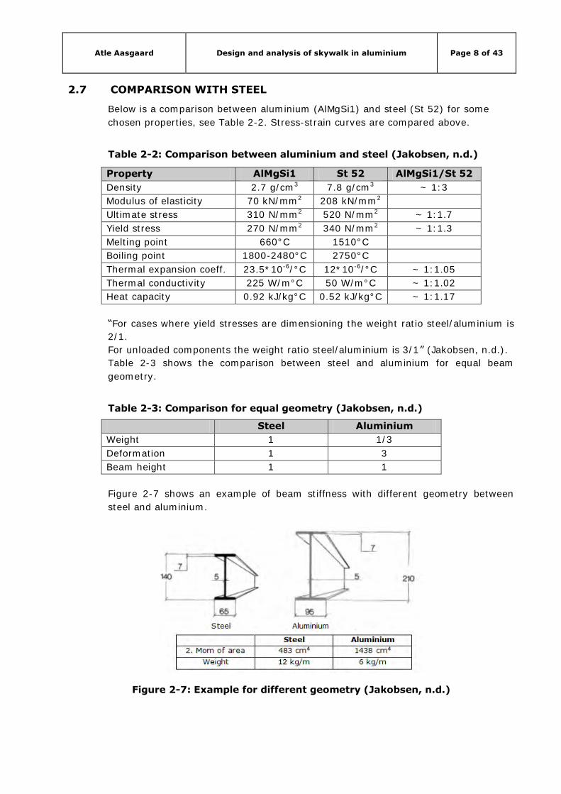
Figure 2-7 shows an example of beam stiffness with different geometry between
steel and aluminium.
Figure 2-7: Example for different geometry (Jakobsen, n.d.)
Atle Aasgaard Design and analysis of skywalk in aluminium Page 9 of 43
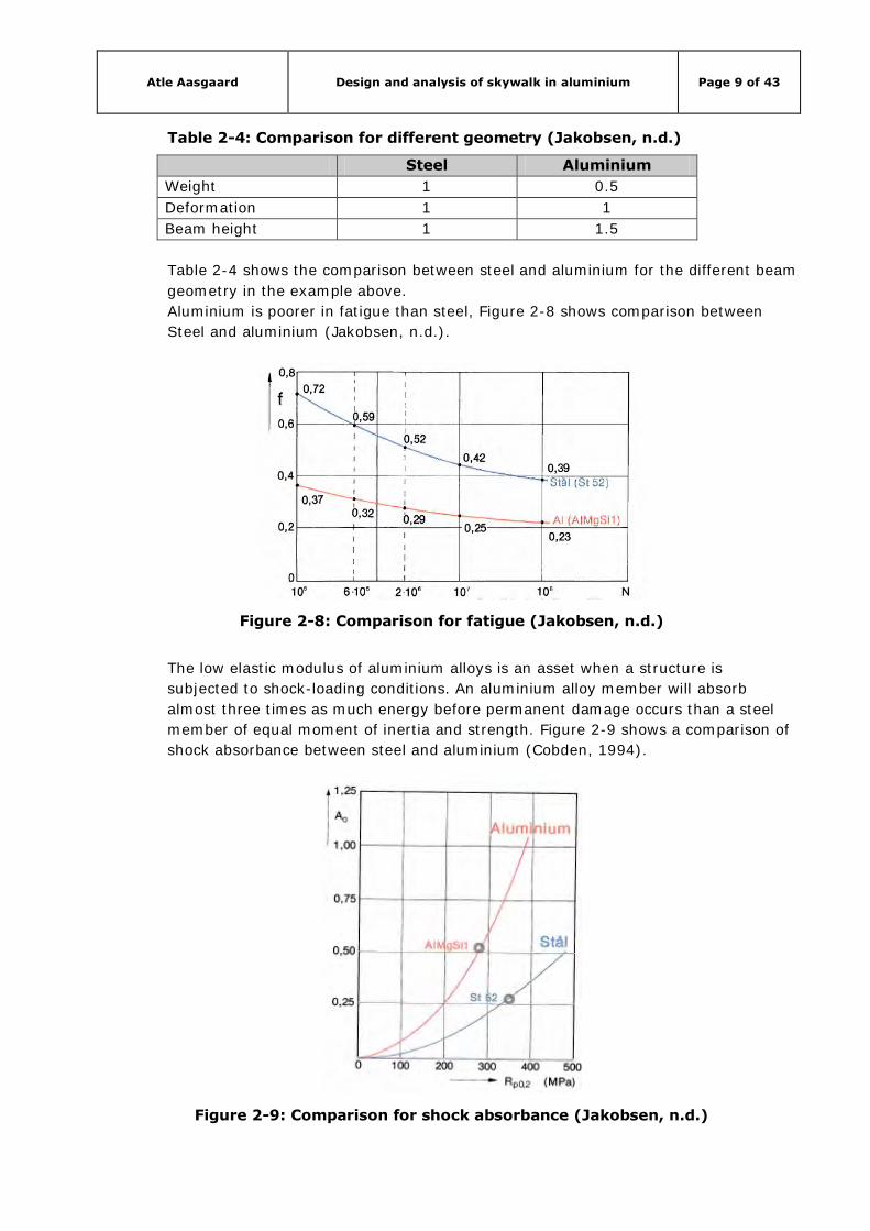
Table 2-4: Comparison for different geometry (Jakobsen, n.d.)
Steel Aluminium
Weight 1 0.5
Deformation 1 1
Beam height 1 1.5
Table 2-4 shows the comparison between steel and aluminium for the different beam
geometry in the example above.
Aluminium is poorer in fatigue than steel, Figure 2-8 shows comparison between
Steel and aluminium (Jakobsen, n.d.).
Figure 2-8: Comparison for fatigue (Jakobsen, n.d.)
The low elastic modulus of aluminium alloys is an asset when a structure is
subjected to shock-loading conditions. An aluminium alloy member will absorb
almost three times as much energy before permanent damage occurs than a steel
member of equal moment of inertia and strength. Figure 2-9 shows a comparison of
shock absorbance between steel and aluminium (Cobden, 1994).
Figure 2-9: Comparison for shock absorbance (Jakobsen, n.d.)

Atle Aasgaard Design and analysis of skywalk in aluminium Page 10 of 43
Aluminium has good resistance against corrosion. Figure 2-10 shows comparison
between steel and aluminium. The upper graph shows general rate of corrosion in a
maritime environment. The lower graph shows average rate of corrosion after 20
years in sea water (Jakobsen, n.d.).
Figure 2-10: Comparison for corrosion (Jakobsen, n.d.)
2.8 ALUMINIUM ALLOYS
2.8.1 Numbering and designation
Pure aluminium must be strengthened to be used for structural applications. There
are many different alloy series. Aluminium alloys are grouped into wrought
aluminium alloys and cast aluminium alloys. Wrought alloys are divided into eight
alloy series 1xxx-8xxx. They are further subdivided into heat-treatable (HT) and
non-heat-treatable (NHT). See Table 2-5.
Table 2-5: Numerical wrought alloy designation system
Series Alloy elements Type
1xxx None NHT
2xxx Copper (Cu) HT
3xxx Manganese (Mn) NHT
4xxx Silicon (Si) NHT
5xxx Magnesium (Mg) NHT
6xxx Magnesium and silicon (MgSi) HT
7xxx Zinc (Zn) HT
8xxx Other elements

Atle Aasgaard Design and analysis of skywalk in aluminium Page 11 of 43
Cast alloys are divided into nine alloy series 1xxxx-9xxxx, see Table 2-6.
Table 2-6: Numerical cast alloy designation system
Series Alloy elements
1xxxx None
2xxxx Copper (Cu)
3xxxx n/a
4xxxx Silicon (Si)
5xxxx Magnesium (Mg)
6xxxx n/a
7xxxx Zinc (Zn)
8xxxx Tin (Sn)
9xxxx Master alloys
Wrought alloy series:
1xxx series: This series is for commercially pure aluminium, defined as being at least
99% aluminium. This alloy series has very good electrical conductivity and corrosion
resistance, and are often used in plants. It is also used in the food and packaging
industry.
2xxx series: The primary alloying element for this group is copper. It produces high
strength but also reduced corrosion resistance, reduced ductility and poor
extrudability. This series is mainly used by the aerospace industry.
3xxx series: In this series manganese is the primary alloying element. This series
has a tensile strength of approximately 200 N/mm2 and are not much stronger than
pure aluminium. It has very high corrosion resistance and good workability, and are
used in cladding of buildings and car panelling.
4xxx series: In this series silicon is added to reduce the melting point and it is used
for castings and weld filler wire.
5xxx series: By adding magnesium this series gets a combination of high strength
and excellent resistance to corrosion. It is used for vessels, vehicles, ships and
chemical plants.
6xxx series: This alloy series contains magnesium and silicon. They have high
strength, excellent extrudability, and good corrosion resistance. It has a tensile
strength around 300 N/mm2 and proof stress of 250 N/mm2. This series include the
6082 alloy which is widely used for building structures.

Atle Aasgaard Design and analysis of skywalk in aluminium Page 12 of 43
7xxx series: The primary alloying element in this series is zinc. These alloys display
the highest strength of aluminium alloys, and can reach a tensile strength of 580
N/mm2. It has poorer corrosion resistance and extrudability than the 6xxx series,
and is mainly used for aircrafts and military.
8xxx series: This series is reserved for alloying elements other than those used for
the 1xxx-7xxx series.
(Müller, 2011)
2.8.2 Temper designation
Aluminium alloys are available in different tempers. By heat treatment the
mechanical properties of the heat-treatable alloys can be changed. Heat is therefore
used to strengthen or soften the material. There are five basic temper designations
used for aluminium alloy temper designation. These groupings are represented by
the letters F, O, H, W and T. See Table 2-7.
Table 2-7: Basic temper designation
Letter Description Meaning
F As fabricated Forming process with no special control over
thermal or strain hardening
O Annealed Heat treated to give min. strength improving
ductility and dimensionality
H Strain hardened Strengthened by cold working
W Heat treated Solution heat treated but produces an
unstable temper
T Heat treated Thermally heat treated with or without
additional strain hardening
The groups for strain-hardened alloys (H) and thermally heat treated alloys (T) are
further subdivided indicating the applied treatment or treatment combinations.
Subdivisions of the strain-hardened and HT aluminium alloys are done by adding
numerical indicators to the preceding letters. The range of the strain-hardened alloys
is H1–H4 and HX2–HX8. The subgroups for the heat treated alloys are T1–T9. See
Table 2-8. (Müller, 2011).

Atle Aasgaard Design and analysis of skywalk in aluminium Page 13 of 43
Table 2-8: Temper designation system to current standards
Temper destination (xxxx)
-F As fabricated
-O Fully annealed
-H1 Strain-hardened only NHT
-H2 Strain-hardened and partially annealed NHT
-H3 Strain-hardened and stabilised NHT
-H4 Strain-hardened and lacquered or painted NHT
-HX2 Quarter-hard NHT
-HX4 Half-hard NHT
-HX6 Three-quarter-hard NHT
-HX8 Fully-hard NHT
-T1 Cooled from an elevated termperature
shaping process
HT
-T2 Cooled from an elevated termperature
shaping process, cold worked and naturally
aged
HT
-T3 Solution heat-treated, cold worked and
naturally aged
HT
-T4 Solution heat-treated and naturally aged HT
-T5 Cooled from an elevated termperature
shaping process and artificially aged
HT
-T6 Solution heat-treated and artificially aged HT
-T7 Solution heat-treated and over-aged HT
-T8 Solution heat-treated, cold worked, and
then artificially aged
HT
-T9 Solution heat-treated, artificially aged and
then cold worked
HT
To explain the numbering and designation system the commonly used aluminium
alloy 6082-T6 is used:
6=group 6xxx (magnesium and silicon)
0=original alloy (not modified)
82=group specific allocator
T6=heat treated and artificially aged
2.9 JOINTING ALUMINIUM
2.9.1 General
There are many ways of jointing aluminium members. But for primary structures the
joints normally are welded connections, bolted connections, riveted connections or
adhesive joints.
Atle Aasgaard Design and analysis of skywalk in aluminium Page 14 of 43
2.9.2 Mechanical joints
Mechanical joints formed by bolting, screwing, riveting and pinning are frequently
used as methods when jointing aluminium. Compared to welded joints they have the
advantage that there is no softening due to the influence of heat. Fasteners for use
in aluminium and aluminium alloy structures can be made of:
aluminium/aluminium alloy
steel (mild steel)
stainless steel.
Fasteners made of aluminium/aluminium alloy have the advantage of avoiding
galvanic corrosion and also thermal expansion problems.
Fasteners made of mild steel need to be isolated from the aluminium in order to
avoid galvanic corrosion.
Fasteners made of austenitic stainless steel do not suffer from galvanic corrosion
when in contact with aluminium. It also has higher strength then fasteners made of
aluminium/aluminium alloy.
2.9.3 Welded joints
Aluminium structural elements are often jointed by welding. There are a lot of
advantages of welded connections, such as simplicity of connections and design, less
material required compared to bolted connections. However there is one big
disadvantage of welded connections which is softening of the heat-affected zone.
2.9.4 Bonded joints
“Adhesive bonding is defined as the process of joining parts using a non-metallic
substance which undergoes a physical or chemical hardening reaction causing the
parts to join together through surface adherence and internal strength of the
adhesive” (European aluminium association, Matter, 2001-2010)
It is not widely used in structural applications, but is an alternative to welding and
mechanical jointing.
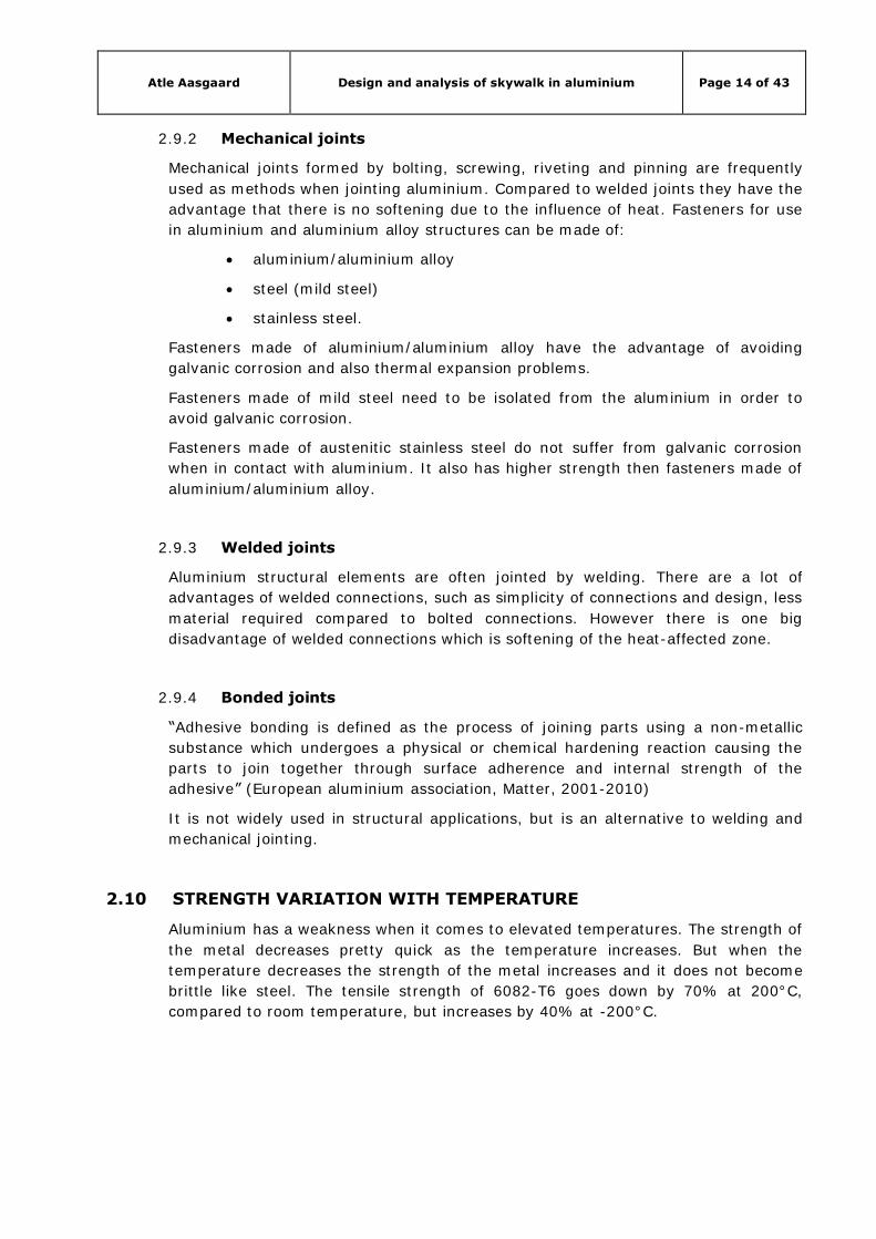
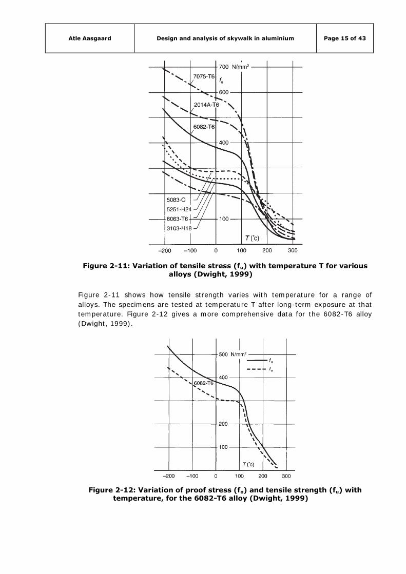
2.10 STRENGTH VARIATION WITH TEMPERATURE
Aluminium has a weakness when it comes to elevated temperatures. The strength of
the metal decreases pretty quick as the temperature increases. But when the
temperature decreases the strength of the metal increases and it does not become
brittle like steel. The tensile strength of 6082-T6 goes down by 70% at 200°C,
compared to room temperature, but increases by 40% at -200°C.
Atle Aasgaard Design and analysis of skywalk in aluminium Page 15 of 43
Figure 2-11: Variation of tensile stress (fu) with temperature T for various alloys (Dwight, 1999)
Figure 2-11 shows how tensile strength varies with temperature for a range of
alloys. The specimens are tested at temperature T after long-term exposure at that
temperature. Figure 2-12 gives a more comprehensive data for the 6082-T6 alloy
(Dwight, 1999).
Figure 2-12: Variation of proof stress (fo) and tensile strength (fu) with temperature, for the 6082-T6 alloy (Dwight, 1999)

Atle Aasgaard Design and analysis of skywalk in aluminium Page 16 of 43
2.11 HEAT AFFECTED ZONE
An annoying feature in aluminium construction is the weakening of the metal around
welds, known as heat affected zone (HAZ) softening, see Figure 2-13. Most
aluminium alloys used in structural applications have mechanical properties based or
improved by cold-working or heat treatment. When welding these aluminium alloy
members, heat generated by the welding process reduces material properties in the
HAZ.
Figure 2-13: HAZ softening at aluminium welds (Dwight, 1999)
The reduction in strength can be locally reduced in the parent metal strength by
nearly one half. Table 2-9 shows an extract from Eurocode 9, table 3.2b,
(NS-EN 1999-1-1).
Table 2-9: Characteristic values of 0.2% proof strength f0 and ultimate
tensile strength fu for unwelded and for HAZ for alloy EN-AW 6082
2.12 CORROSION
Aluminium has good resistance to corrosion in most environments and many
chemical agents. Any aluminium surface exposed to air develops a thin oxide film.
Although very thin this layer prevents further oxidation. As long as oxygen is
available this oxide film will reform if damaged. This gives aluminium a good
durability. In most aluminium installations, no protection against surface corrosion is
necessary, except for the sake of appearance.
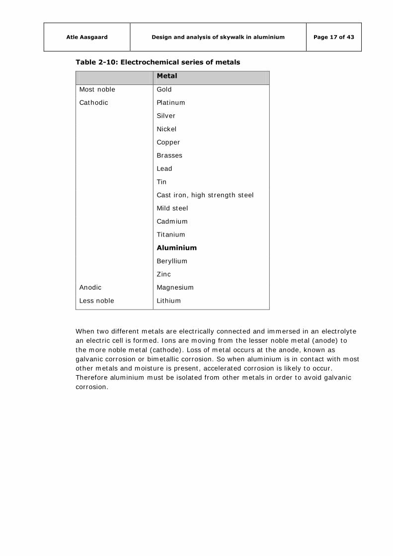
Unfortunately, aluminium is a base metal, and is less noble than most of the other
metals used in construction. See Table 2-10.
Atle Aasgaard Design and analysis of skywalk in aluminium Page 17 of 43
Table 2-10: Electrochemical series of metals
Metal
Most noble Gold
Cathodic Platinum
Silver
Nickel
Copper
Brasses
Lead
Tin
Cast iron, high strength steel
Mild steel
Cadmium
Titanium
Aluminium
Beryllium
Zinc
Anodic Magnesium
Less noble Lithium
When two different metals are electrically connected and immersed in an electrolyte
an electric cell is formed. Ions are moving from the lesser noble metal (anode) to
the more noble metal (cathode). Loss of metal occurs at the anode, known as
galvanic corrosion or bimetallic corrosion. So when aluminium is in contact with most
other metals and moisture is present, accelerated corrosion is likely to occur.
Therefore aluminium must be isolated from other metals in order to avoid galvanic
corrosion.

Atle Aasgaard Design and analysis of skywalk in aluminium Page 18 of 43
3. DESIGN AND GEOMETRY
3.1 GENERAL
The skywalk is designed to fit the surrounding buildings, which mainly consists of
white and black rectangular buildings. The figures below are meant as illustrations
and are not accurate.
Figure 3-1: Design of skywalk
Figure 3-1 shows an overview of the design of the skywalk, and how it interacts with
surrounding buildings. The figure is an illustration and the size and shape of the
surrounding buildings are arbitrarily.
Figure 3-2 shows the skywalk without surroundings, and one can see how the
skywalk enters the buildings on each side of the clearance between them.
Atle Aasgaard Design and analysis of skywalk in aluminium Page 19 of 43
Figure 3-2: Design of skywalk 2
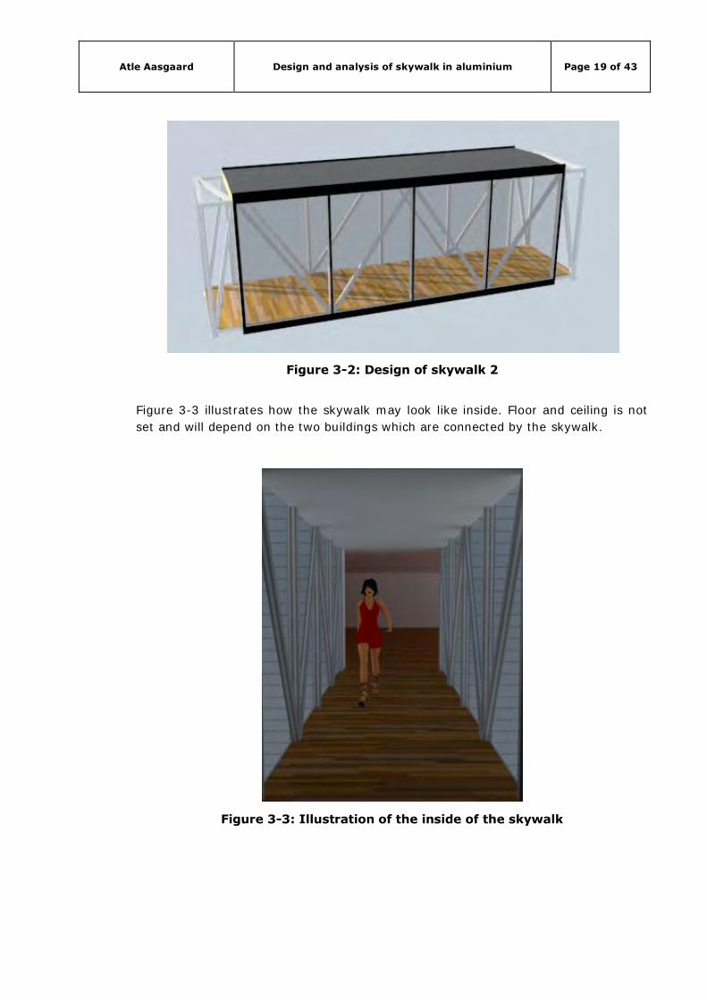
Figure 3-3 illustrates how the skywalk may look like inside. Floor and ceiling is not
set and will depend on the two buildings which are connected by the skywalk.
Figure 3-3: Illustration of the inside of the skywalk

Atle Aasgaard Design and analysis of skywalk in aluminium Page 20 of 43
3.2 GEOMETRY AND PROPERTIES
3.2.1 Geometry
The skywalk spans between two buildings. The clearance between the two buildings
is 7.25 metres. The length of the skywalk is 8.4 metres, the width is 2.0 metres and
the height is 2.6 metres. See Figure 3-4.
Figure 3-4: Model of bearing structure
3.3 SUPPORT POINTS
The structure will be landing on four support points, one in each corner. See Figure
3-5.
Figure 3-5: Support points
Atle Aasgaard Design and analysis of skywalk in aluminium Page 21 of 43
The support points needs to able to comprehend movements of the structure. The
aluminium structure also needs to be isolated at the support points in order to
prevent galvanic corrosion. The foot plate on the aluminium structure will be resting
on an anchored steel plate, with a layer of neoprene between them. See Figure 3-6
for an illustration.
Figure 3-6: Illustration of Support point
The neoprene will isolate the aluminium from the steel, and it will allow the structure
to move.
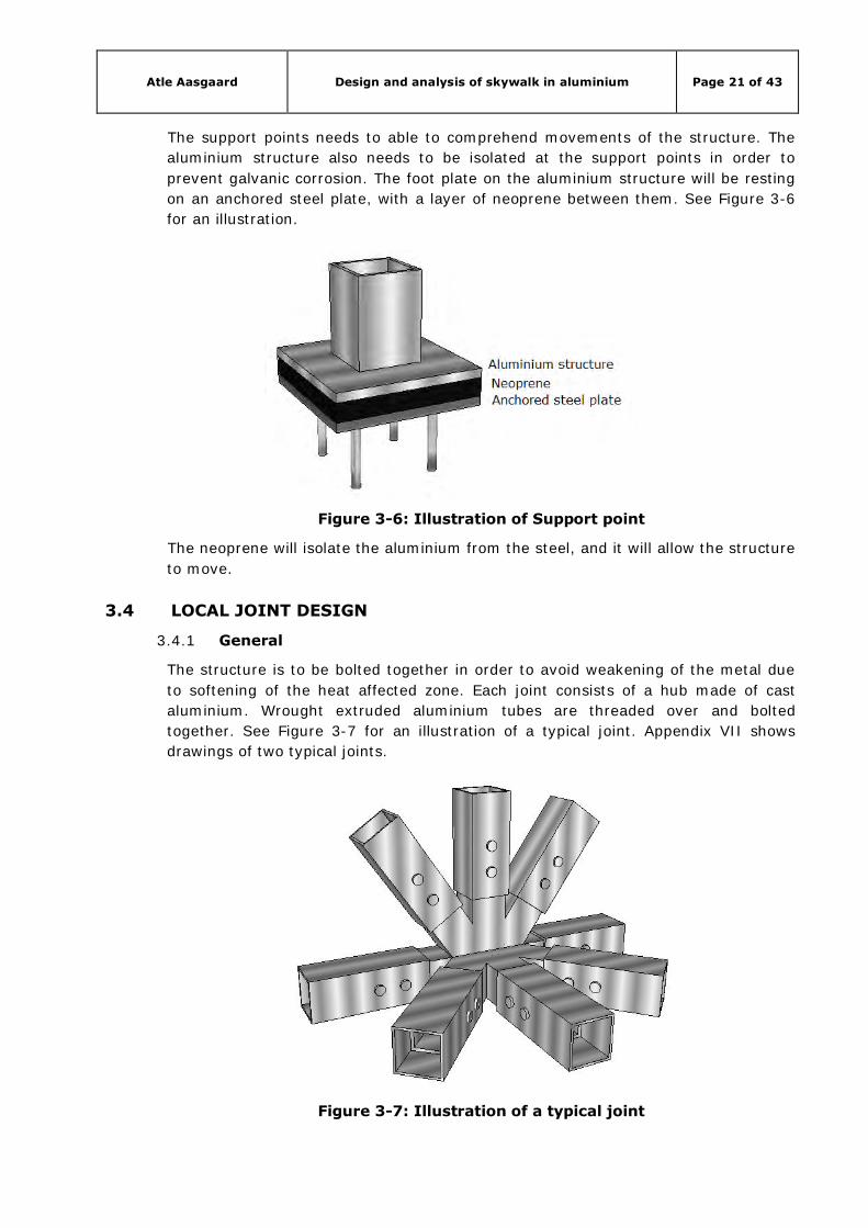
3.4 LOCAL JOINT DESIGN
3.4.1 General
The structure is to be bolted together in order to avoid weakening of the metal due
to softening of the heat affected zone. Each joint consists of a hub made of cast
aluminium. Wrought extruded aluminium tubes are threaded over and bolted
together. See Figure 3-7 for an illustration of a typical joint. Appendix VII shows
drawings of two typical joints.
Figure 3-7: Illustration of a typical joint
Atle Aasgaard Design and analysis of skywalk in aluminium Page 22 of 43
3.5 LIFTING ARRANGEMENT
The aluminium structure will be lifted into place by a mobile or fixed crane. The
aluminium structure has low self weight, about 600 kg (5.8 kN) (Appendix III or
chapter 6), and can easily be lifted using straps.
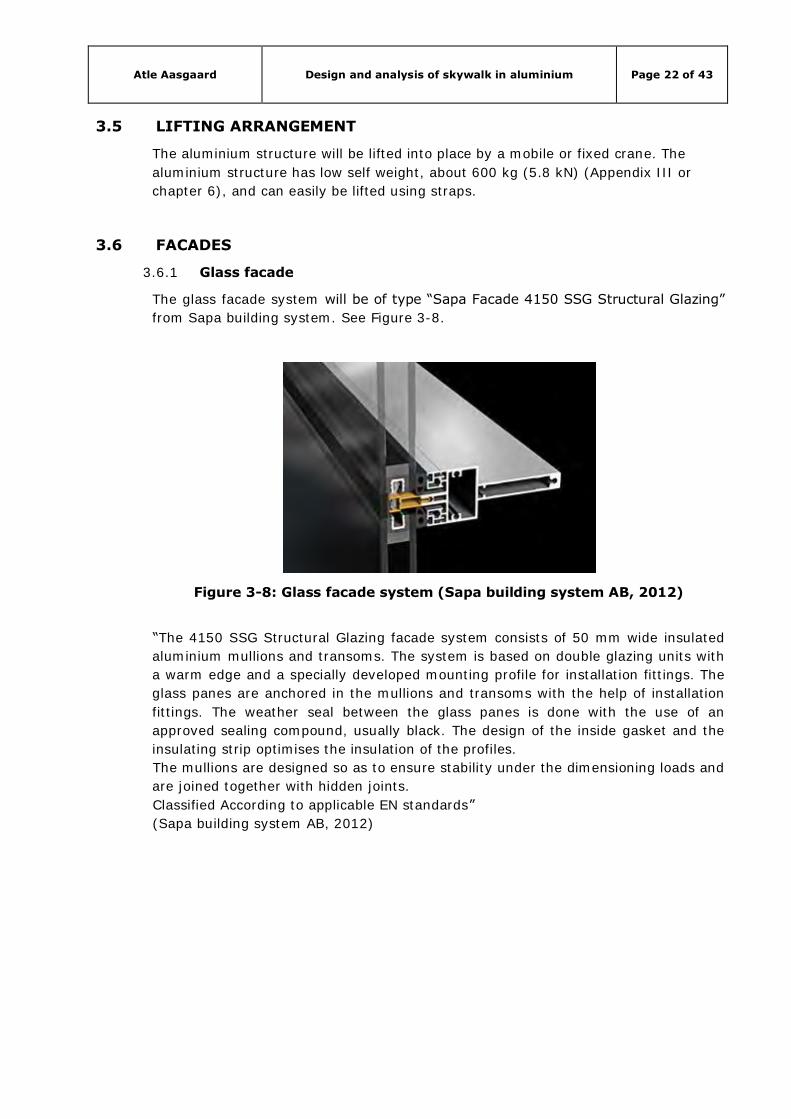
3.6 FACADES
3.6.1 Glass facade
The glass facade system will be of type “Sapa Facade 4150 SSG Structural Glazing”
from Sapa building system. See Figure 3-8.
Figure 3-8: Glass facade system (Sapa building system AB, 2012)
“The 4150 SSG Structural Glazing facade system consists of 50 mm wide insulated
aluminium mullions and transoms. The system is based on double glazing units with
a warm edge and a specially developed mounting profile for installation fittings. The
glass panes are anchored in the mullions and transoms with the help of installation
fittings. The weather seal between the glass panes is done with the use of an
approved sealing compound, usually black. The design of the inside gasket and the
insulating strip optimises the insulation of the profiles.
The mullions are designed so as to ensure stability under the dimensioning loads and
are joined together with hidden joints.
Classified According to applicable EN standards”
(Sapa building system AB, 2012)
Atle Aasgaard Design and analysis of skywalk in aluminium Page 23 of 43
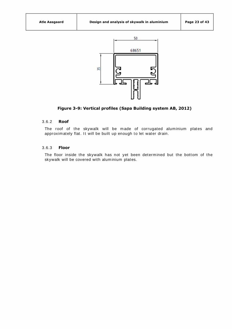
Figure 3-9: Vertical profiles (Sapa Building system AB, 2012)
3.6.2 Roof
The roof of the skywalk will be made of corrugated aluminium plates and approximately flat. It will be built up enough to let water drain.
3.6.3 Floor
The floor inside the skywalk has not yet been determined but the bottom of the skywalk will be covered with aluminium plates.
Atle Aasgaard Design and analysis of skywalk in aluminium Page 24 of 43
4. LOADS AND LOADING CONDITIONS
4.1 LOAD CASES
The skywalk is subjected to various permanent and variable loads. The characteristic
values are defined in Table 4-1 below:
Table 4-1: Load cases
Load case Type of load Load
LC1 Self-weight aluminium 27.0 kN/m3
LC2 Self-weight glass facade 0.4 kN/m2
LC3 Self-weight roof 1.0 kN/m2
LC4 Self-weight floor 1.0 kN/m2
LC5 Live load C3 5.0 kN/m2
LC6 Snow load 1.5 kN/m2
LC7 Wind load 1.0 kN/m2
LC8 2 falling persons 1.7 kN
LC1, self-weight of aluminium, and are calculated by STAAD Pro v8i in the analysis.
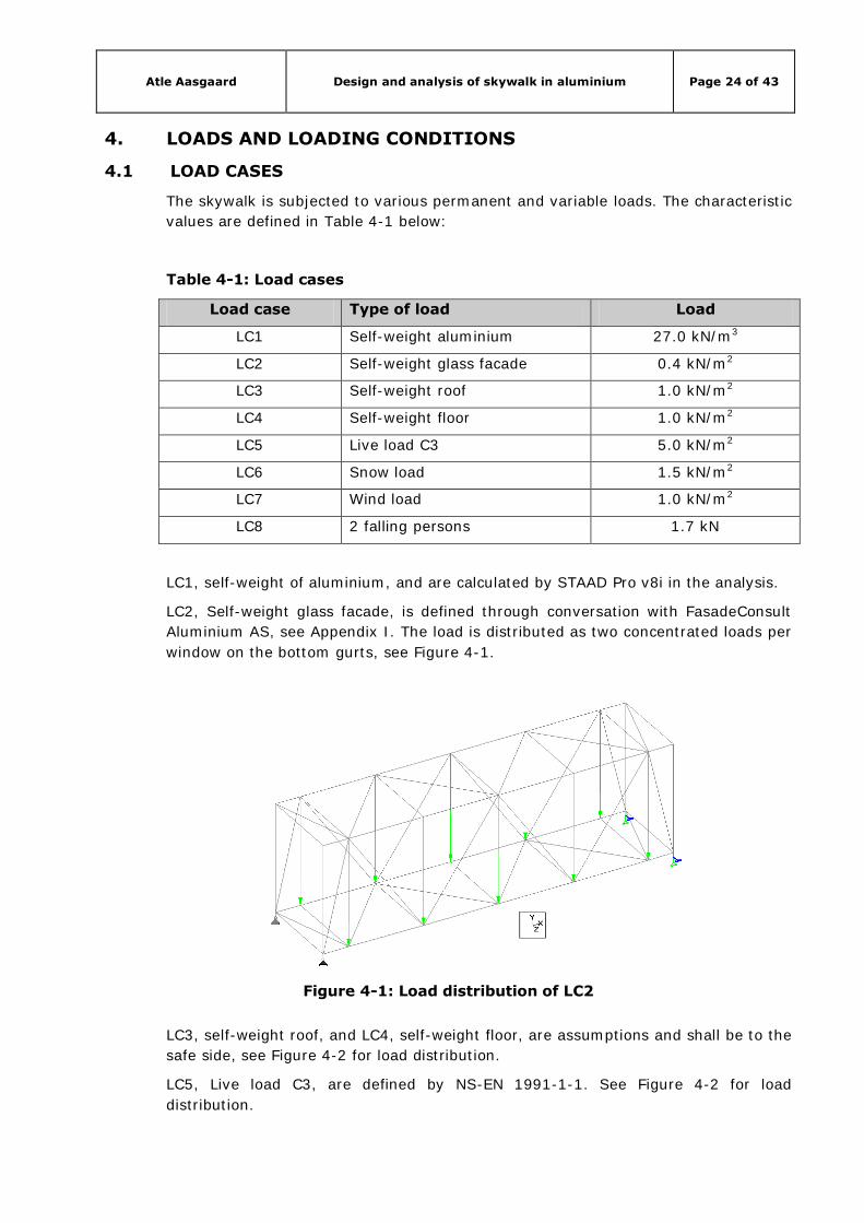
LC2, Self-weight glass facade, is defined through conversation with FasadeConsult
Aluminium AS, see Appendix I. The load is distributed as two concentrated loads per
window on the bottom gurts, see Figure 4-1.
Figure 4-1: Load distribution of LC2
LC3, self-weight roof, and LC4, self-weight floor, are assumptions and shall be to the
safe side, see Figure 4-2 for load distribution.
LC5, Live load C3, are defined by NS-EN 1991-1-1. See Figure 4-2 for load
distribution.

Atle Aasgaard Design and analysis of skywalk in aluminium Page 25 of 43
LC6, Snow load, is defined by NS-EN 1991-1-3, see Appendix I for calculations. See
Figure 4-2 for load distribution.
Figure 4-2: Load distribution of LC3-LC6
LC7, Wind load, is defined by NS-EN 1991-1-4 and calculated in Appendix I. Wind
load is applied in both Z-direction and –Z-direction. Figure 4-3 shows the distribution
of wind load in –Z-direction.
Figure 4-3: Load distribution of LC7
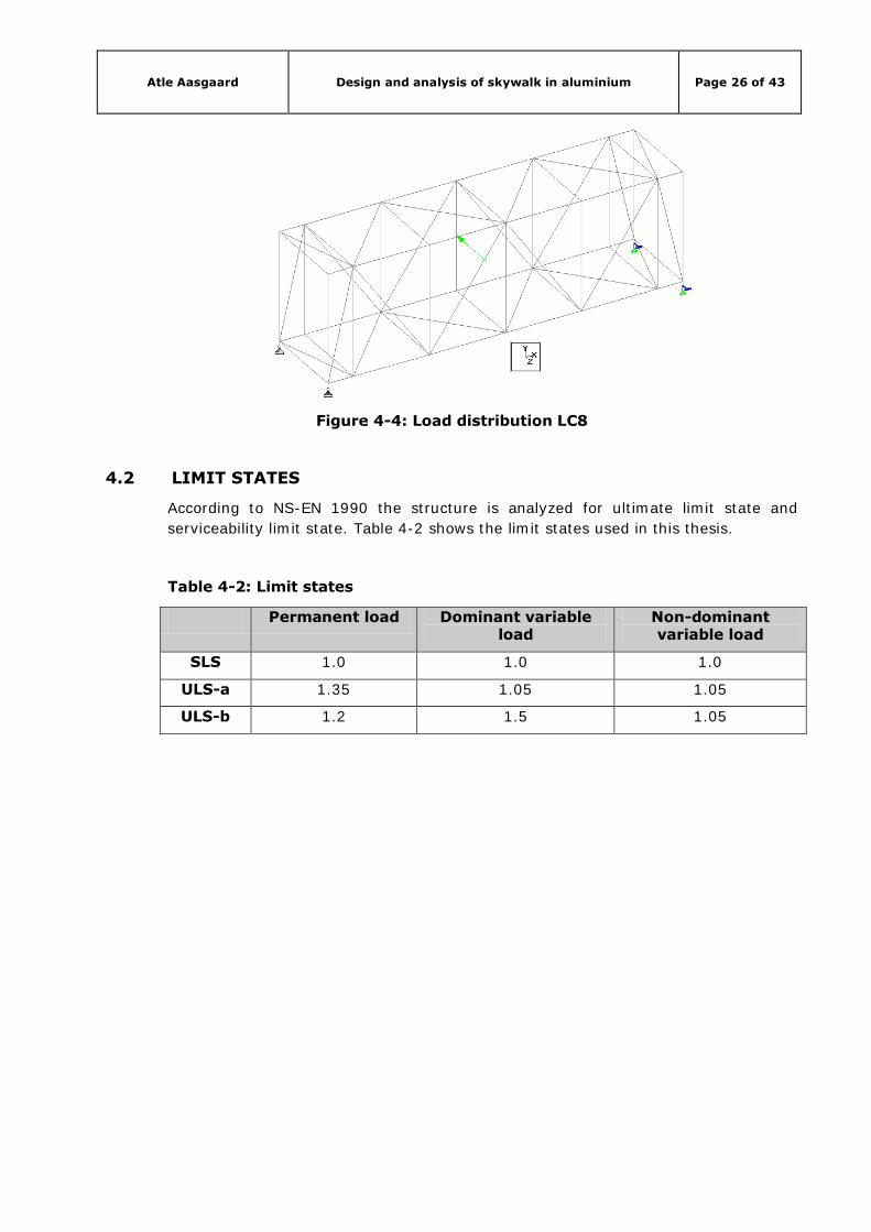
Due to the instability of aluminium an additional load representing 2 drunken
persons (2x85 kg) falling into the wall of the skywalk has been included. This load is
represented as a static horizontal concentrated load of 1.7 kN at the middle of the
skywalk. See Figure 4-4 for load distribution.
Atle Aasgaard Design and analysis of skywalk in aluminium Page 26 of 43
Figure 4-4: Load distribution LC8
4.2 LIMIT STATES
According to NS-EN 1990 the structure is analyzed for ultimate limit state and
serviceability limit state. Table 4-2 shows the limit states used in this thesis.
Table 4-2: Limit states
Permanent load Dominant variable load
Non-dominant variable load
SLS 1.0 1.0 1.0
ULS-a 1.35 1.05 1.05
ULS-b 1.2 1.5 1.05

Atle Aasgaard Design and analysis of skywalk in aluminium Page 27 of 43
5. DESIGN INPUT FOR MODEL
5.1 GENERAL
The skywalk has been modelled as a space frame model and analyzed using STAAD
Pro v8i. In addition to loads and limit states given in chapter 4 input for the STAAD
Pro v8i analyze is given below.
5.2 UNITS
Following SI units are used as analysis database units:
Length - metres (m)
Force - kilo Newton (kN)
5.3 GLOBAL COORDINATE SYSTEM
Conventional Cartesian coordinate system: This coordinate system Figure 5-1 is a
rectangular coordinate system (X, Y, Z) which follows the orthogonal right hand rule.
This coordinate system may be used to define the joint locations and loading
directions. The translational degrees of freedom are denoted by u1, u2, u3 and the
rotational degrees of freedom are denoted by u4, u5 & u6.
Figure 5-1: Cartesian (rectangular) coordinate system
5.4 LOCAL COORDINATE SYSTEM
A local coordinate system is associated with each member. Each axis of the local
orthogonal coordinate system is also based on the right hand rule. Figure 5-2 shows
a beam member with start joint 'i' and end joint 'j'. The positive direction of the local
x-axis is determined by joining 'i' to 'j' and projecting it in the same direction. The
right hand rule may be applied to obtain the positive directions of the local y and z
axes. The local y and z-axes coincide with the axes of the two principal moments of
inertia. Note that the local coordinate system is always rectangular.
Atle Aasgaard Design and analysis of skywalk in aluminium Page 28 of 43
Figure 5-2: Local coordinate system
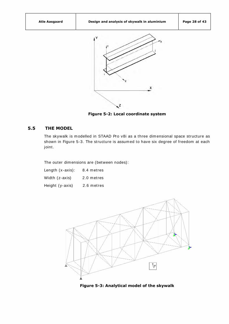
5.5 THE MODEL
The skywalk is modelled in STAAD Pro v8i as a three dimensional space structure as
shown in Figure 5-3. The structure is assumed to have six degree of freedom at each
joint.
The outer dimensions are (between nodes):
Length (x-axis): 8.4 metres
Width (z-axis) 2.0 metres
Height (y-axis) 2.6 metres
Figure 5-3: Analytical model of the skywalk
Atle Aasgaard Design and analysis of skywalk in aluminium Page 29 of 43
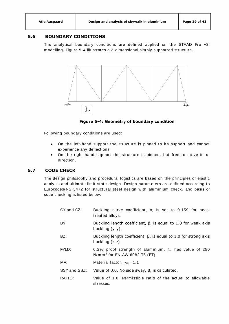
5.6 BOUNDARY CONDITIONS
The analytical boundary conditions are defined applied on the STAAD Pro v8i
modelling. Figure 5-4 illustrates a 2-dimensional simply supported structure.
Figure 5-4: Geometry of boundary condition
Following boundary conditions are used:
On the left-hand support the structure is pinned to its support and cannot
experience any deflections
On the right-hand support the structure is pinned, but free to move in x-
direction.
5.7 CODE CHECK
The design philosophy and procedural logistics are based on the principles of elastic
analysis and ultimate limit state design. Design parameters are defined according to
Eurocodes/NS 3472 for structural steel design with aluminium check, and basis of
code checking is listed below:
CY and CZ: Buckling curve coefficient, α, is set to 0.159 for heat-
treated alloys.
BY: Buckling length coefficient, β, is equal to 1.0 for weak axis
buckling (y-y).
BZ: Buckling length coefficient, β, is equal to 1.0 for strong axis
buckling (z-z)
FYLD: 0.2% proof strength of aluminium, fo, has value of 250
N/mm2 for EN-AW 6082 T6 (ET).
MF: Material factor, γM1=1.1
SSY and SSZ: Value of 0.0. No side sway, β, is calculated.
RATIO: Value of 1.0. Permissible ratio of the actual to allowable
stresses.
Atle Aasgaard Design and analysis of skywalk in aluminium Page 30 of 43
CMZ: Value of 0.21 αLT for sections in connection with lateral
buckling.
DMAX: 1.0 m, maximum allowable depth of section.
DMIN: 0.0 m, minimum allowable depth of section
5.8 MATERIAL
5.8.1 Material properties
The following material properties applied for the structure:
Modulus of elasticity: E=70 000 N/mm2
Shear modulus: G=27 000 N/mm2
Poisson’s ratio: ν=0.3
Coefficient of linear thermal expansion: α=23x10-6 per °C
Unit mass: ρ=2 700 kg/m3
5.8.2 Profiles
The profiles used in this structure are extruded tubes of wrought aluminium alloy
EN-AW 6082 T6. Table 5-1 shows the characteristic values for the profiles.
Table 5-1: Characteristic values for profiles
Profile Alloy designation Temper fo fu A
Numerical Chemical N/mm2 %
TUB80804 EN-AW 6082
EN-AW AlSi1MgMn
T6 250 290 8
Where fo is the 0.2% proof strength, fu is the ultimate tensile strength and A is the
min elongation.
5.8.3 Joints
The joints are chill cast aluminium hubs joining tubes of size 70x70x5 mm. NS-EN
1706:2010 specifies alloy EN-AC 42200-T6 and are only valid for separately cast test
specimens. Table 5-2 shows the characteristic values for the cast joints.
Atle Aasgaard Design and analysis of skywalk in aluminium Page 31 of 43
Table 5-2: Characteristic values for joints
Profile Alloy designation Temper fo fu A
Numerical Chemical N/mm2 %
TUB70705 EN-AC 42200
EN-AC AlSi7Mg0.6
T6 240 320 3
Where fo is the 0.2% proof strength, fu is the ultimate tensile strength and A is the
min elongation.
5.8.4 Bolts
For the bolted connections aluminium bolts M16 shall be used. Table 5-3 shows the
characteristic values for the aluminium bolts.
Table 5-3: Characteristic values for bolts
Bolt Alloy designation fo fu
Numerical Chemical N/mm2
M16 EN-AW 6082
EN-AW AlSi1MgMn
260 310
Where fo is the 0.2% proof strength, fu is the ultimate tensile strength.
5.8.5 Partial safety factors/material factors
According to NS-EN 1999-1-1 the partial safety factors to be used are set as follows:
5.9 CALCULATION OF FORCES AND BENDING MOMENTS
Elastic analysis method is used to obtain the forces and moments for design.
Analysis is done for the primary loading conditions and combinations.
5.9.1 Member with only axial forces
For tension only members, axial tension capacity is checked for ultimate limit stress.
For compression members, axial compression capacity is checked in addition to
lateral buckling and ultimate limit stress. The coefficient α is specified in both
directions through the parameters CY and CZ (see 5.9.4 Aluminium check)

Atle Aasgaard Design and analysis of skywalk in aluminium Page 32 of 43
5.9.2 Members with axial force and bending moment
For compression members with bending, interaction formulae of NS 3472 table
12.3.4.2 are used for checking member capacity.
The equivalent moment factor β is calculated using the procedure of NS 3472 table
12. Two different approaches are used depending upon whether the members can
sway or not. Conditions for side sway and transverse loading are specified through
the use of parameters SSY and SSZ. For member that cannot sway, without
transverse loading, coefficients β should be calculated and proper dimensioning
moments are used in the interaction formulae.
5.9.3 Von Mises yield criterion
Combined effect of axial, bending, horizontal/vertical shear and torsional shear
stress is calculated at 13 sections on a member and up to 5 critical points at a
section for tube profile, see Figure 5-5 and Table 5-4. The worst stress value is
checked against yield stress divided by appropriate material factor.
The general von Mises stress calculates as:
The design resistance are obtained by dividing the characteristic material strength
by the material factor and the nominal stresses should satisfy
Note! For aluminium the 0.2% proof strength fo is used instead of fy.

Atle Aasgaard Design and analysis of skywalk in aluminium Page 33 of 43
Figure 5-5: Geometry of tube section
Ax, Ix, Iy, Iz and
are taken from STAAD Pro v8i database.
Ay=2ht and Az=2
bt
Table 5-4: Stress calculation at selected points
5.9.4 Aluminium check
STAAD Pro v8i performs stability check on aluminium alloys according to buckling
curve in ECCS (European recommendation for aluminium alloy structures 1978). It is
possible to select heat-treated or non heat treated alloy from the parameter list in
the STAAD Pro v8i input file.
Atle Aasgaard Design and analysis of skywalk in aluminium Page 34 of 43
For heat-treated use CY=CZ=0.159, and for non heat-treated use CY=CZ=0.242.
Tracks 1.0 and 9.0 print buckling curve H for heat-treated, and buckling curve N for
non heat-treated. The yield check is the same as for steel.
5.10 LOCAL JOINT CHECK
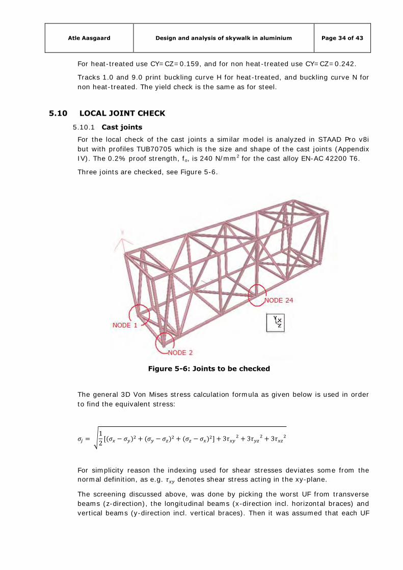
5.10.1 Cast joints
For the local check of the cast joints a similar model is analyzed in STAAD Pro v8i
but with profiles TUB70705 which is the size and shape of the cast joints (Appendix
IV). The 0.2% proof strength, fo, is 240 N/mm2 for the cast alloy EN-AC 42200 T6.
Three joints are checked, see Figure 5-6.
Figure 5-6: Joints to be checked
The general 3D Von Mises stress calculation formula as given below is used in order
to find the equivalent stress:
For simplicity reason the indexing used for shear stresses deviates some from the
normal definition, as e.g. denotes shear stress acting in the xy-plane.
The screening discussed above, was done by picking the worst UF from transverse
beams (z-direction), the longitudinal beams (x-direction incl. horizontal braces) and
vertical beams (y-direction incl. vertical braces). Then it was assumed that each UF

Atle Aasgaard Design and analysis of skywalk in aluminium Page 35 of 43
represent the maximum normal stress from x-, y- and z-direction respectively
( ), i.e. not dimensioned by shear stress. Hence, the above formula can be
written as follows:
Then, eliminating fd, the expression is reduced to only include UF’s. It is obvious the
sign of stresses is significant in order to find the maximum possible combined UF. A
study of this effect, resulted in a rewritten formula, where the utilisation in each
direction is sorted such that UFmax ≥ UFmed ≥ UFmin. It was then found that worst
situation is found if the maximum stress is of opposite sign than the two other
components. Hence, the final formula for an equivalent maximum Von Mises
utilisation in a node could then be written as follows:
which leads to:
For calculations, see Appendix V.
5.10.2 Bolted connections
The bolted connections are checked against the largest beam end force of the beams
that are bolted. The forces are taken from the STAAD Pro v8i analysis (TUB80804).
The connections are checked according to NS-EN 1999-1-1.
Atle Aasgaard Design and analysis of skywalk in aluminium Page 36 of 43
6. ANALYSIS RESULTS
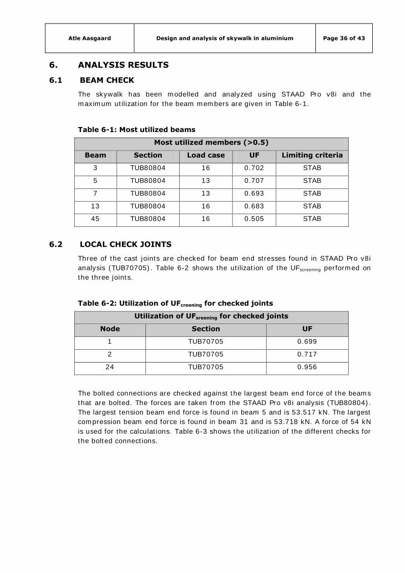
6.1 BEAM CHECK
The skywalk has been modelled and analyzed using STAAD Pro v8i and the
maximum utilization for the beam members are given in Table 6-1.
Table 6-1: Most utilized beams
Most utilized members (>0.5)
Beam Section Load case UF Limiting criteria
3 TUB80804 16 0.702 STAB
5 TUB80804 13 0.707 STAB
7 TUB80804 13 0.693 STAB
13 TUB80804 16 0.683 STAB
45 TUB80804 16 0.505 STAB
6.2 LOCAL CHECK JOINTS
Three of the cast joints are checked for beam end stresses found in STAAD Pro v8i
analysis (TUB70705). Table 6-2 shows the utilization of the UFscreening performed on
the three joints.
Table 6-2: Utilization of UFcreening for checked joints
Utilization of UFsreening for checked joints
Node Section UF
1 TUB70705 0.699
2 TUB70705 0.717
24 TUB70705 0.956
The bolted connections are checked against the largest beam end force of the beams
that are bolted. The forces are taken from the STAAD Pro v8i analysis (TUB80804).
The largest tension beam end force is found in beam 5 and is 53.517 kN. The largest
compression beam end force is found in beam 31 and is 53.718 kN. A force of 54 kN
is used for the calculations. Table 6-3 shows the utilization of the different checks for
the bolted connections.
Atle Aasgaard Design and analysis of skywalk in aluminium Page 37 of 43
Table 6-3: Utilization for bolted joints
Utilization for bolted joints (max F = 54 kN)
Criteria Section UF
Shear resistance M16 0.578
Bearing resistance TUB80804 0.624
Parent material TUB80804 0.241
Block tearing resistance TUB80804 0.300
6.3 DEFLECTION
Table 6-4 shows a summary of maximum node deflection in the two different
serviceability limit states (SLS), one with horizontal loads in Z-direction and one with
horizontal loads in –Z-direction.
Table 6-4: Summary node displacement (STAAD Pro v8i)
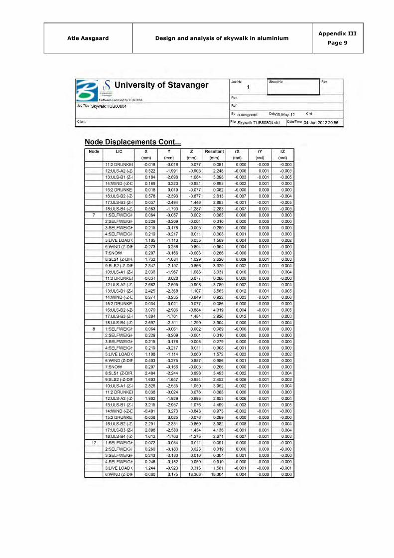
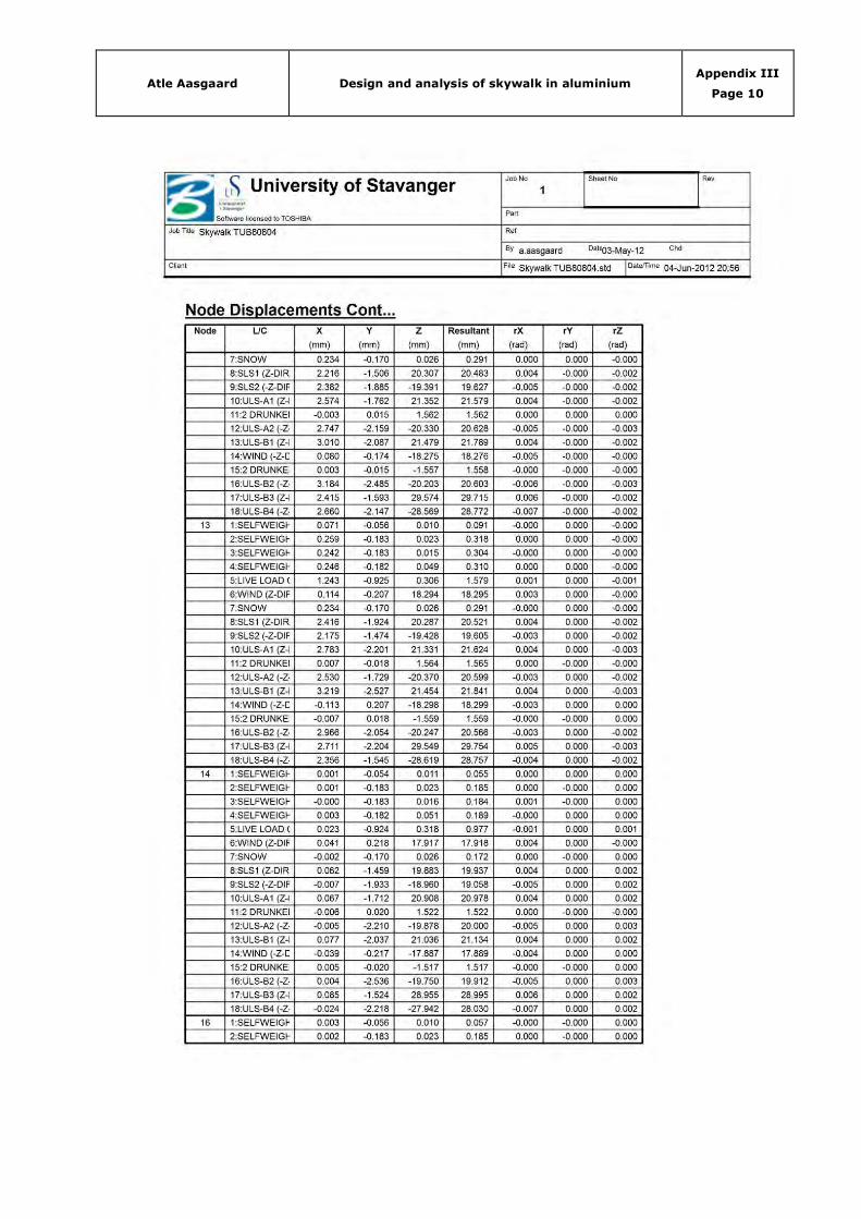
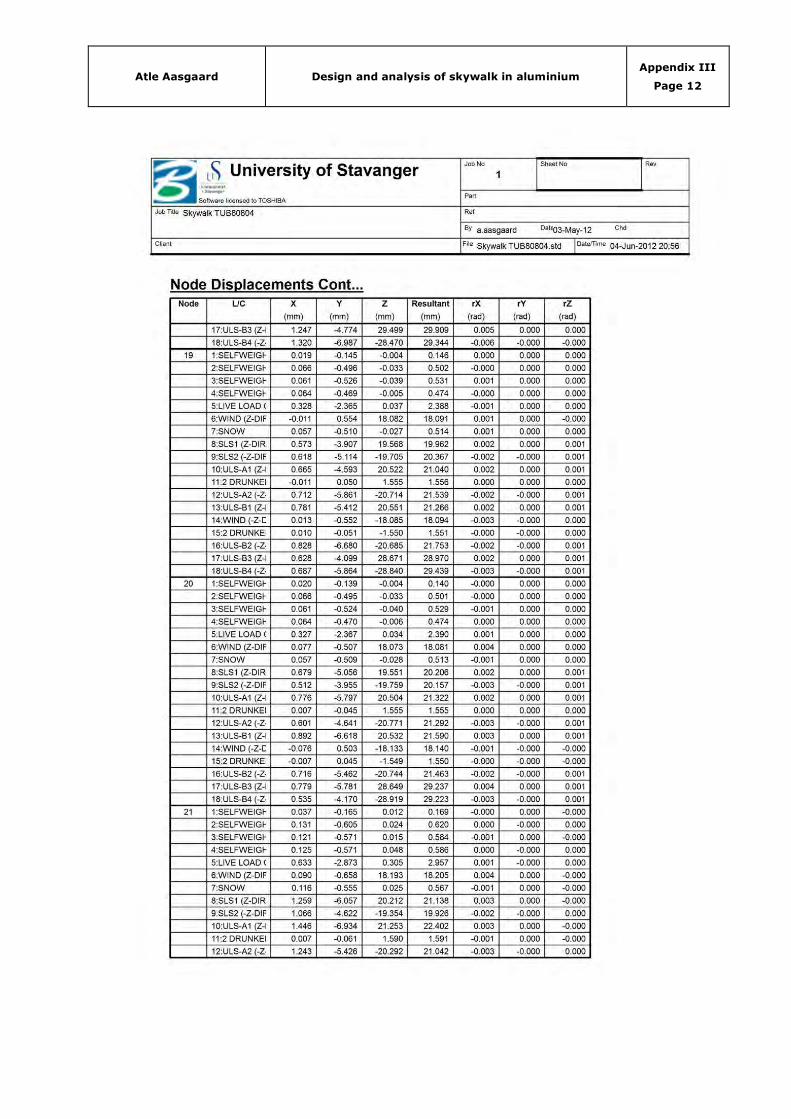
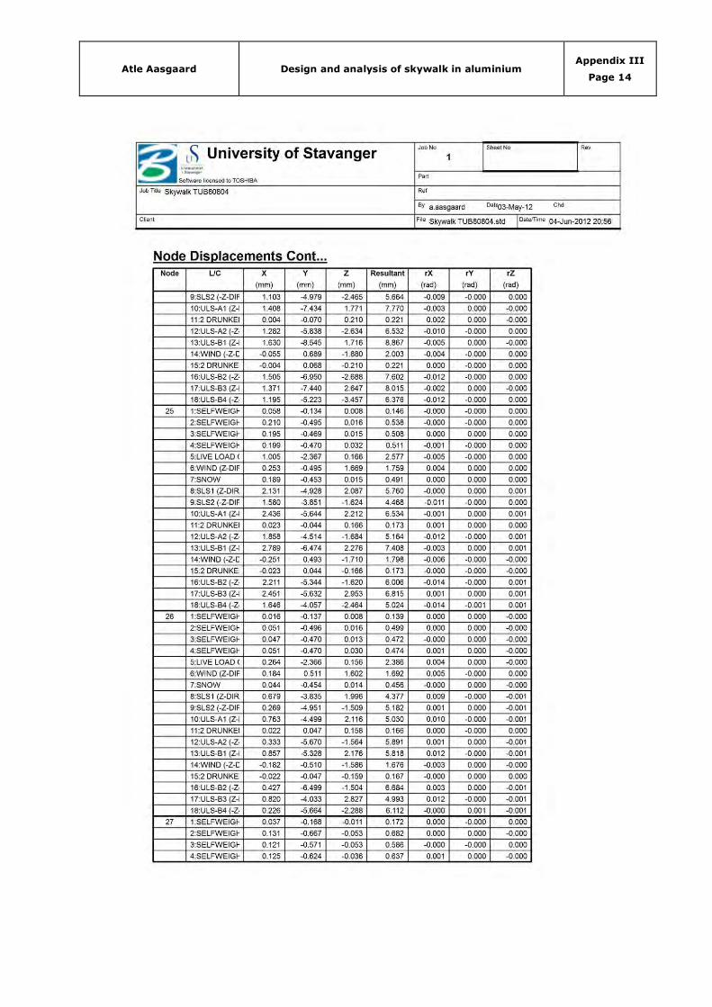
Maximum deflections of the four middle nodes of the skywalk are listed in Table 6-5
below. Figure 6-1 shows the node number of the four middle nodes.
Figure 6-1: Four middle nodes
Atle Aasgaard Design and analysis of skywalk in aluminium Page 38 of 43
Table 6-5: Max. node displacement for selected nodes (SLS)
Node LC Displacement [mm]
X Y Z
18 8 1.138 -4.569 20.266
9 1.189 -6.087 -19.337
21 8 1.259 -6.057 20.212
9 1.066 -4.622 -19.354
24 8 1.222 -6.499 1.730
9 1.103 -4.979 -2.465
27 8 1.148 -4.934 1.787
9 1.179 -6.501 -2.501
6.4 SUPPORT REACTION
Figure 6-2 shows the number of the support nodes.
Figure 6-2: Support nodes
Table 6-6 gives a summary of reaction forces. Load case 1 (Self-weight of
aluminium), the worst serviceability limit state and the worst ultimate limit state are
included.

Atle Aasgaard Design and analysis of skywalk in aluminium Page 39 of 43
Table 6-6: Summary reaction forces
Summary reaction forces
Node LC FX [kN] FY [kN] FZ [kN]
29 1 (Self-weight alu.) -0.002 1.454 0.091
9 (Max SLS) 7.103 47.228 14.134
16 (Max ULS) 7.480 61.596 16.859
30 1 (Self-weight alu.) 0.002 1.454 0.091
8 (Max SLS) 6.988 47.225 -8.250
13 (Max ULS) 7.315 61.591 -10.676
31 1 (Self-weight alu.) 0.000 1.454 0.091
9 (Max SLS) 0.000 46.796 11.832
16 (Max ULS) 0.000 61.140 14.435
32 1 (Self-weight alu.) 0.000 1.454 -0.091
8 (Max SLS) 0.000 46.799 -7.187
13 (Max ULS) 0.000 61.145 -9.563
Atle Aasgaard Design and analysis of skywalk in aluminium Page 40 of 43
7. CONCLUSION
The main focus of this Master’s thesis has been to model and analyze a skywalk in
aluminium between two buildings at the new Aker Solutions office in Jåttåvågen,
Stavanger.
A central part of the work has been to understand the positive and negative
characteristics of aluminium as a structural material.
The STAAD Pro v8i analysis shows that the skywalk has sufficient capacity in the
ultimate limit state, with a maximum utilization, UF, of 0.707 for the beams and
0.956 for the local joint check.
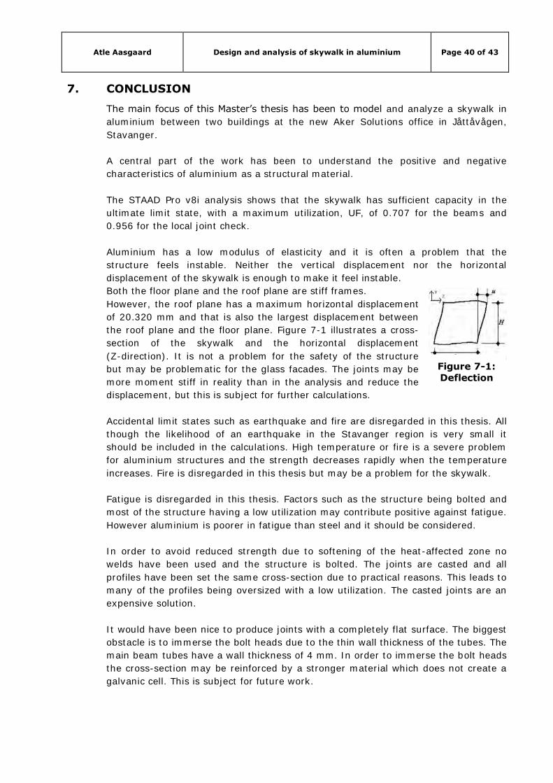
Aluminium has a low modulus of elasticity and it is often a problem that the
structure feels instable. Neither the vertical displacement nor the horizontal
displacement of the skywalk is enough to make it feel instable.
Both the floor plane and the roof plane are stiff frames.
However, the roof plane has a maximum horizontal displacement
of 20.320 mm and that is also the largest displacement between
the roof plane and the floor plane. Figure 7-1 illustrates a cross-
section of the skywalk and the horizontal displacement
(Z-direction). It is not a problem for the safety of the structure
but may be problematic for the glass facades. The joints may be
more moment stiff in reality than in the analysis and reduce the
displacement, but this is subject for further calculations.
Accidental limit states such as earthquake and fire are disregarded in this thesis. All
though the likelihood of an earthquake in the Stavanger region is very small it
should be included in the calculations. High temperature or fire is a severe problem
for aluminium structures and the strength decreases rapidly when the temperature
increases. Fire is disregarded in this thesis but may be a problem for the skywalk.
Fatigue is disregarded in this thesis. Factors such as the structure being bolted and
most of the structure having a low utilization may contribute positive against fatigue.
However aluminium is poorer in fatigue than steel and it should be considered.
In order to avoid reduced strength due to softening of the heat-affected zone no
welds have been used and the structure is bolted. The joints are casted and all
profiles have been set the same cross-section due to practical reasons. This leads to
many of the profiles being oversized with a low utilization. The casted joints are an
expensive solution.
It would have been nice to produce joints with a completely flat surface. The biggest
obstacle is to immerse the bolt heads due to the thin wall thickness of the tubes. The
main beam tubes have a wall thickness of 4 mm. In order to immerse the bolt heads
the cross-section may be reinforced by a stronger material which does not create a
galvanic cell. This is subject for future work.
Figure 7-1: Deflection

Atle Aasgaard Design and analysis of skywalk in aluminium Page 41 of 43
The conclusion is that the skywalk, with limitations, has sufficient capacity. All
though, there may be a problem with the deflection of the glass facades and
stiffness of the joints should be further investigated.
This is no long skywalk and neither weight problems nor corrosion problems are an
issue. Aluminium has a great future as a structural material but in this case a steel
structure would be preferred and probably less expensive.

Atle Aasgaard Design and analysis of skywalk in aluminium Page 42 of 43
REFERENCES
Budd, G., 1999. TALAT Lecture 1101: Resources and Production of Aluminium, s.l.: European
aluminium association.
Cobden, R., 1994. TALAT Lecture 1501: Aluminium: Physical properties, characteristics and
alloys, s.l.: European aluminium assosiation.
Dwight, J., 1999. Aluminium design and construction [E-book]. 2002 ed. London: Taylor &
Francis e-Library.
European aluminium association, Matter, 2001-2010. AluMATTER: Mechanical Fastening and
Adhesive Bonding. [Online]
Available at:
http://aluminium.matter.org.uk/content/html/eng/default.asp?catid=217&pageid=21444171
37
[Accessed 10 4 2012].
European aluminium assosiation, Matter, 2001-2010. AluMATTER: Aluminium v steel: Stress-
strain behavior. [Online]
Available at:
http://aluminium.matter.org.uk/content/html/eng/default.asp?catid=217&pageid=21444171
31
[Accessed 2 6 2012].
European committee for standardization, 2002. NS-EN 1990:2002+NA:2008 Eurocode 0:
Basis of structural design. Brusels: European committee of standardization.
European committee for standardization, 2002. NS-EN 1991-1-1:2002+NA:2008 Eurocode 1:
Actions on structures, Part 1-1: General actions: Densities, self-weight, imposed loads for
buildings. Brussels: European committee for standardization.
European committee for standardization, 2003. NS-EN 1991-1-3:2003+NA:2008 Eurocode 1:
Actions on structures, Part 1-3: General actions: Snow loads. Brussels: European committee
for standardization.
European committee for standardization, 2005. NS-EN 1991-1-4:2005+NA:2009 Eurocode 1:
Actions on structures, Part 1-4: General actions: Wind actions. Brussels: European
committee for standardization.
European committee for standardization, 2009. NS-EN 1999-1-1:2007+A1:2009+NA:2009
Eurocode 9: Design of aluminium structures, Part 1-1: General structural rules, Brussels:
European committee for standardization.
European committee for standardization, 2010. NS-EN 1706:2010 Aluminium and aluminium
alloys, castings, chemical composition and machanical properties. Brussels: European
committee for standardization.
Atle Aasgaard Design and analysis of skywalk in aluminium Page 43 of 43
Jakobsen, R. A., n.d. Offshore projecting, Aluminium after input from "Norsk Hydro",
Stavanger: Universirty of Stavanger.
Kissell, J. R. & Ferry, R. L., 2002. Aluminium structures: a guide to their specifications and
design. 2nd red. New York: John Wiley & sons, inc..
Müller, U., 2011. Introduction to structural aluminium design. s.l.:Whittles Publishing.
Sapa building system AB, 2012. [Online]
Available at: http://www.sapagroup.com/en/company-sites/sapa-building-system-
ab/sapa_building_system_ab_gb/products/facades/sapa-4150-ssg-facade-structural-glazing/
[Accessed 5 May 2012].
Sapa building system AB, 2012. [Online]
Available at: http://www.sapagroup.com/Buildingsystem_import/Dimensions/A4150-
4008_en.pdf
[Accessed 5 May 2012].
Sapa building system AB, 2012. [Online]
Available at: http://www.sapagroup.com/Buildingsystem_import/DescriptionTexts/A4150-
4002_en.pdf
[Accessed 5 May 2012].
Sapa Building system AB, 2012. [Online]
Available at: http://www.sapagroup.com/Buildingsystem_import/DescriptionTexts/A4150-
3007_.pdf
[Accessed 5 May 2012].

Atle Aasgaard Design and analysis of skywalk in aluminium Appendix I
Page 0
APPENDIX I – LOADS
(6 Pages to follow)
Title Pages
Wind load 4
Snow load 1
Load of glass facade 1

Atle Aasgaard Design and analysis of skywalk in aluminium Appendix I
Page 1
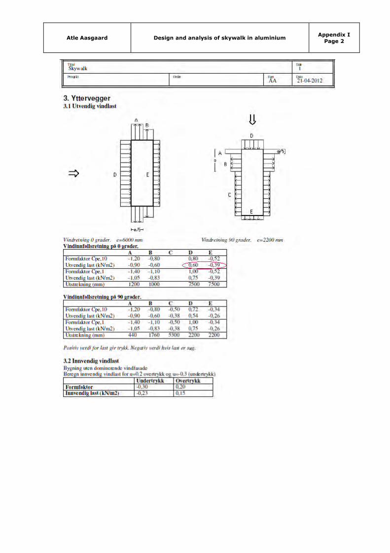
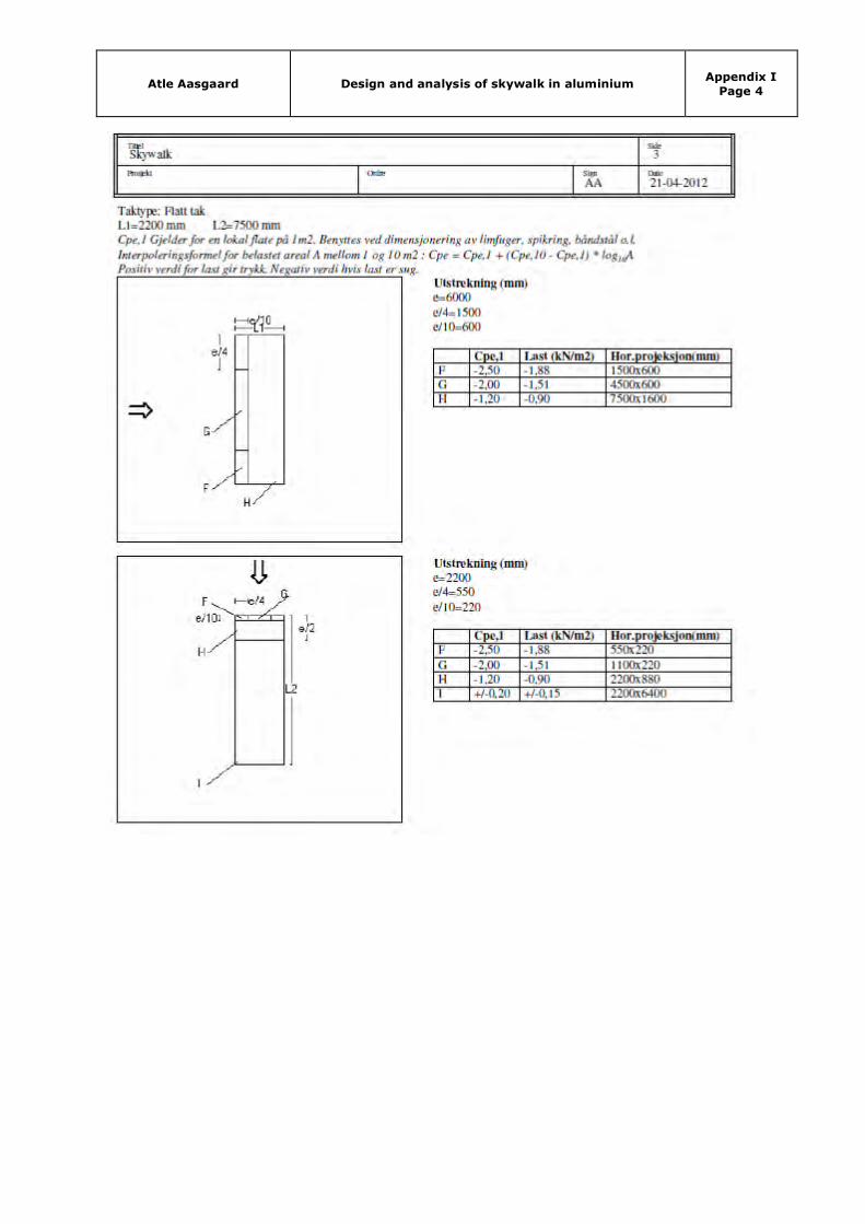
WIND LOAD
Note! The output files from the program used to calculate the windloads are only available in
norwegian, so the wind loads in this appendix are therefore presented in norwegian. The
main results which are used in the report are marked with a red circle.
Atle Aasgaard Design and analysis of skywalk in aluminium Appendix I
Page 2

Atle Aasgaard Design and analysis of skywalk in aluminium Appendix I
Page 3
Atle Aasgaard Design and analysis of skywalk in aluminium Appendix I
Page 4
Atle Aasgaard Design and analysis of skywalk in aluminium Appendix I
Page 5
SNOW LOAD
Place: Stavanger, Rogaland, Norway
Characteristic snow load on ground:
sk,0 = 1.5 kN/m2
Disign value snow load:
s = μi ∙ Ce ∙ Ct ∙ sk
μ1 = 0.8
Ce = 0.8
Ct = 1.0
Sk = 1.5 kN/m2
s = 0.8 ∙ 0.8 ∙ 1.0 ∙ 1.5 kN/m2
s = 0.96 kN/m2 ≈ 1.0 kN/m2

Atle Aasgaard Design and analysis of skywalk in aluminium Appendix I
Page 6
GLASS FACADE
The dead load of the glass facade is set to 0.4 kN/m2 after conversation with fasadeconsult.
Below is an extract from the conversation shown for documentation. Its in norwegian but the
value used is marked with a red circle.
Atle Aasgaard Design and analysis of skywalk in aluminium Appendix II
Page 0
APPENDIX II – GLASS FACADE
(1 Page to follow)
Title Pages
Glass facade dimensioning 1

Atle Aasgaard Design and analysis of skywalk in aluminium Appendix II
Page 1
GLASS FACADE DIMENSIONING

Atle Aasgaard Design and analysis of skywalk in aluminium Appendix III
Page 0
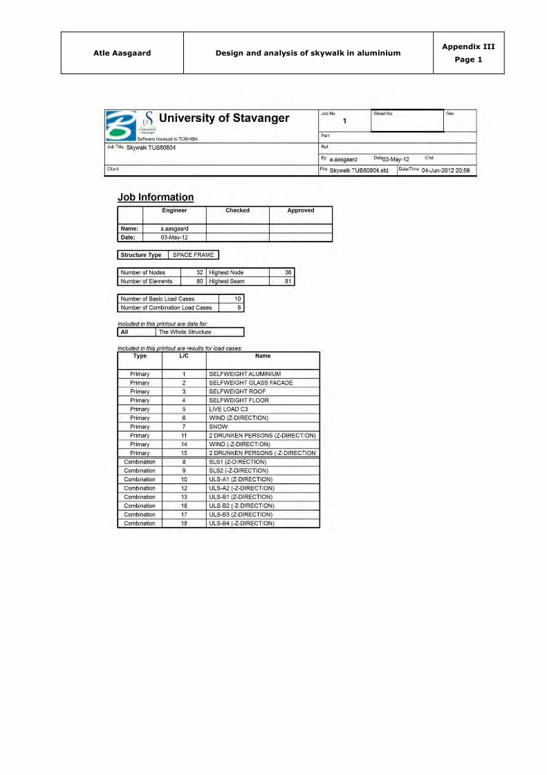
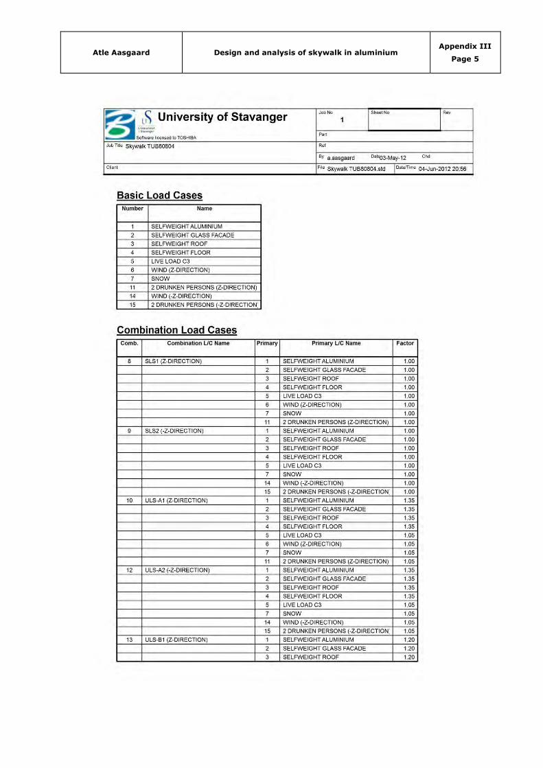
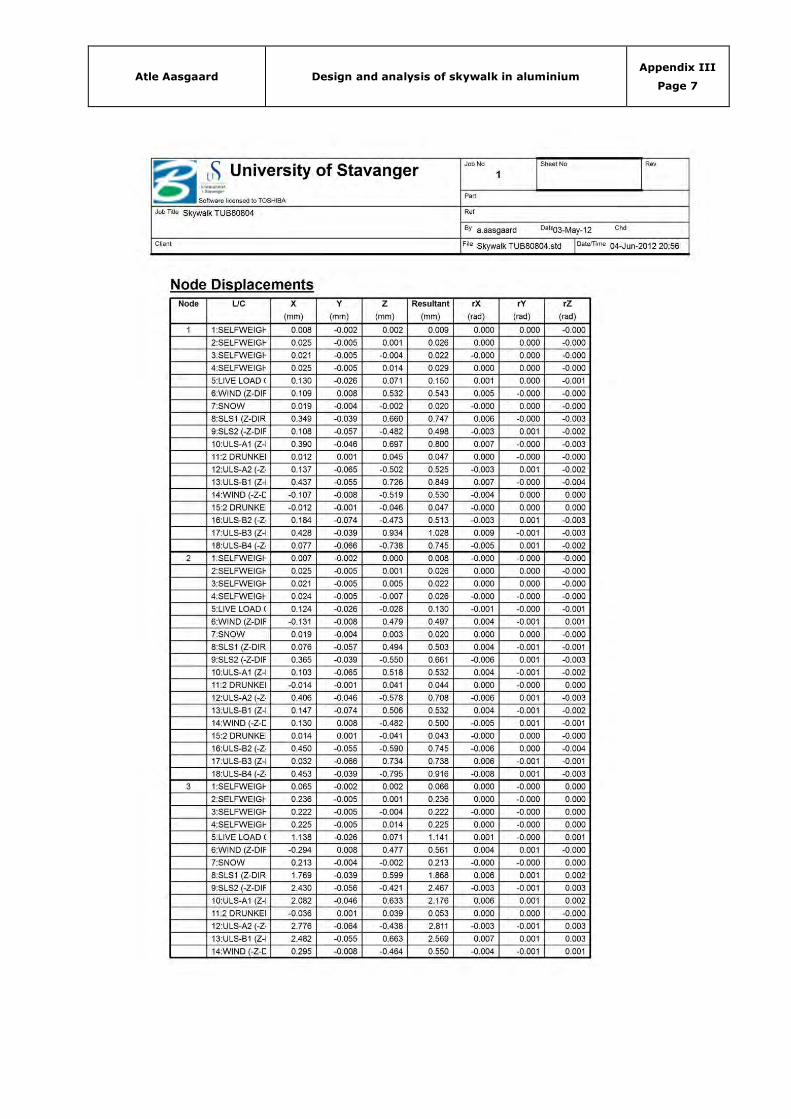
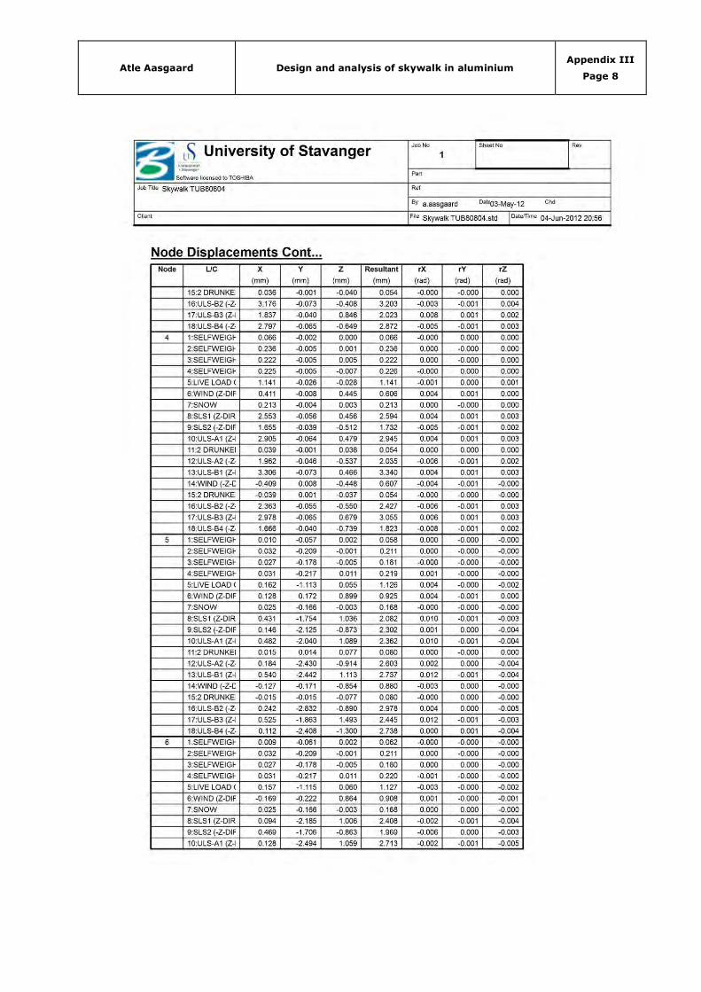
APPENDIX III – STAAD PRO V8I ANALYSIS BEAMS
(42 Pages to follow)
Title Pages
STAAD pro v8i analysis TUB80804 42
Atle Aasgaard Design and analysis of skywalk in aluminium Appendix III
Page 1

Atle Aasgaard Design and analysis of skywalk in aluminium Appendix III
Page 2

Atle Aasgaard Design and analysis of skywalk in aluminium Appendix III
Page 3

Atle Aasgaard Design and analysis of skywalk in aluminium Appendix III
Page 4
Atle Aasgaard Design and analysis of skywalk in aluminium Appendix III
Page 5

Atle Aasgaard Design and analysis of skywalk in aluminium Appendix III
Page 6
Atle Aasgaard Design and analysis of skywalk in aluminium Appendix III
Page 7
Atle Aasgaard Design and analysis of skywalk in aluminium Appendix III
Page 8
Atle Aasgaard Design and analysis of skywalk in aluminium Appendix III
Page 9
Atle Aasgaard Design and analysis of skywalk in aluminium Appendix III
Page 10

Atle Aasgaard Design and analysis of skywalk in aluminium Appendix III
Page 11
Atle Aasgaard Design and analysis of skywalk in aluminium Appendix III
Page 12

Atle Aasgaard Design and analysis of skywalk in aluminium Appendix III
Page 13
Atle Aasgaard Design and analysis of skywalk in aluminium Appendix III
Page 14

Atle Aasgaard Design and analysis of skywalk in aluminium Appendix III
Page 15

Atle Aasgaard Design and analysis of skywalk in aluminium Appendix III
Page 16
Atle Aasgaard Design and analysis of skywalk in aluminium Appendix III
Page 17

Atle Aasgaard Design and analysis of skywalk in aluminium Appendix III
Page 18
Atle Aasgaard Design and analysis of skywalk in aluminium Appendix III
Page 19

Atle Aasgaard Design and analysis of skywalk in aluminium Appendix III
Page 20

Atle Aasgaard Design and analysis of skywalk in aluminium Appendix III
Page 21

Atle Aasgaard Design and analysis of skywalk in aluminium Appendix III
Page 22

Atle Aasgaard Design and analysis of skywalk in aluminium Appendix III
Page 23
Atle Aasgaard Design and analysis of skywalk in aluminium Appendix III
Page 24

Atle Aasgaard Design and analysis of skywalk in aluminium Appendix III
Page 25

Atle Aasgaard Design and analysis of skywalk in aluminium Appendix III
Page 26

Atle Aasgaard Design and analysis of skywalk in aluminium Appendix III
Page 27

Atle Aasgaard Design and analysis of skywalk in aluminium Appendix III
Page 28

Atle Aasgaard Design and analysis of skywalk in aluminium Appendix III
Page 29

Atle Aasgaard Design and analysis of skywalk in aluminium Appendix III
Page 30
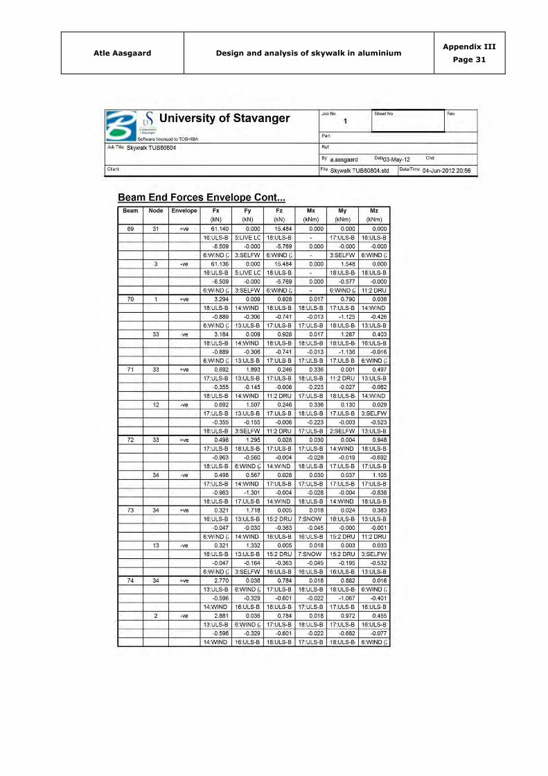
Atle Aasgaard Design and analysis of skywalk in aluminium Appendix III
Page 31
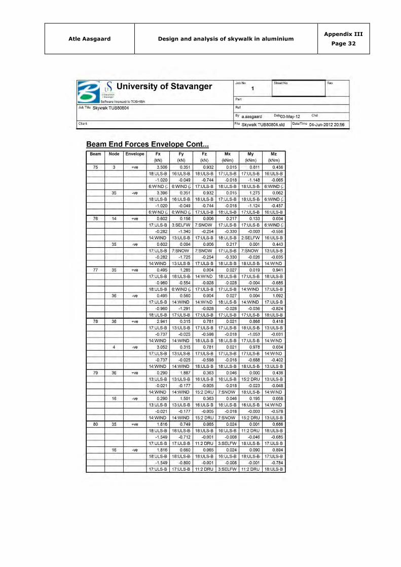
Atle Aasgaard Design and analysis of skywalk in aluminium Appendix III
Page 32

Atle Aasgaard Design and analysis of skywalk in aluminium Appendix III
Page 33
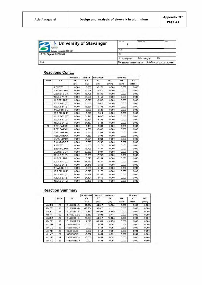
Atle Aasgaard Design and analysis of skywalk in aluminium Appendix III
Page 34
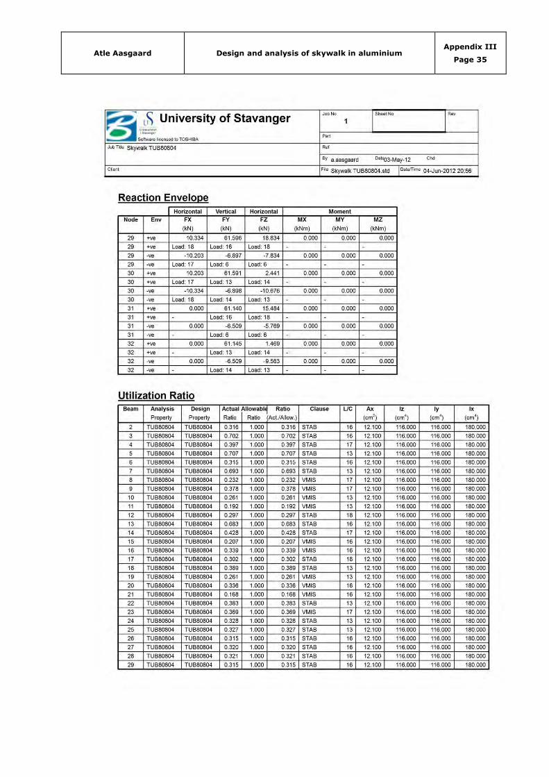
Atle Aasgaard Design and analysis of skywalk in aluminium Appendix III
Page 35

Atle Aasgaard Design and analysis of skywalk in aluminium Appendix III
Page 36
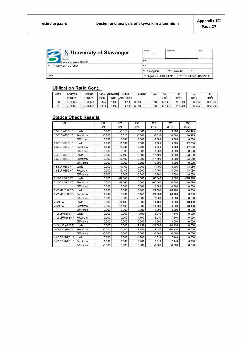
Atle Aasgaard Design and analysis of skywalk in aluminium Appendix III
Page 37

Atle Aasgaard Design and analysis of skywalk in aluminium Appendix III
Page 38

Atle Aasgaard Design and analysis of skywalk in aluminium Appendix III
Page 39
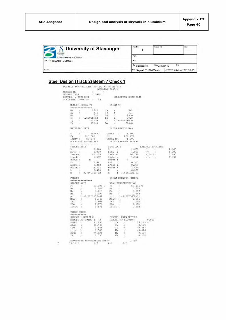
Atle Aasgaard Design and analysis of skywalk in aluminium Appendix III
Page 40

Atle Aasgaard Design and analysis of skywalk in aluminium Appendix III
Page 41

Atle Aasgaard Design and analysis of skywalk in aluminium Appendix III
Page 42

Atle Aasgaard Design and analysis of skywalk in aluminium Appendix IV
Page 0
APPENDIX IV – STAAD PRO V8I ANALYSIS JOINTS
(26 Pages to follow)
Title Pages
STAAD Pro v8i analysis TUB70705 26

Atle Aasgaard Design and analysis of skywalk in aluminium Appendix IV
Page 1
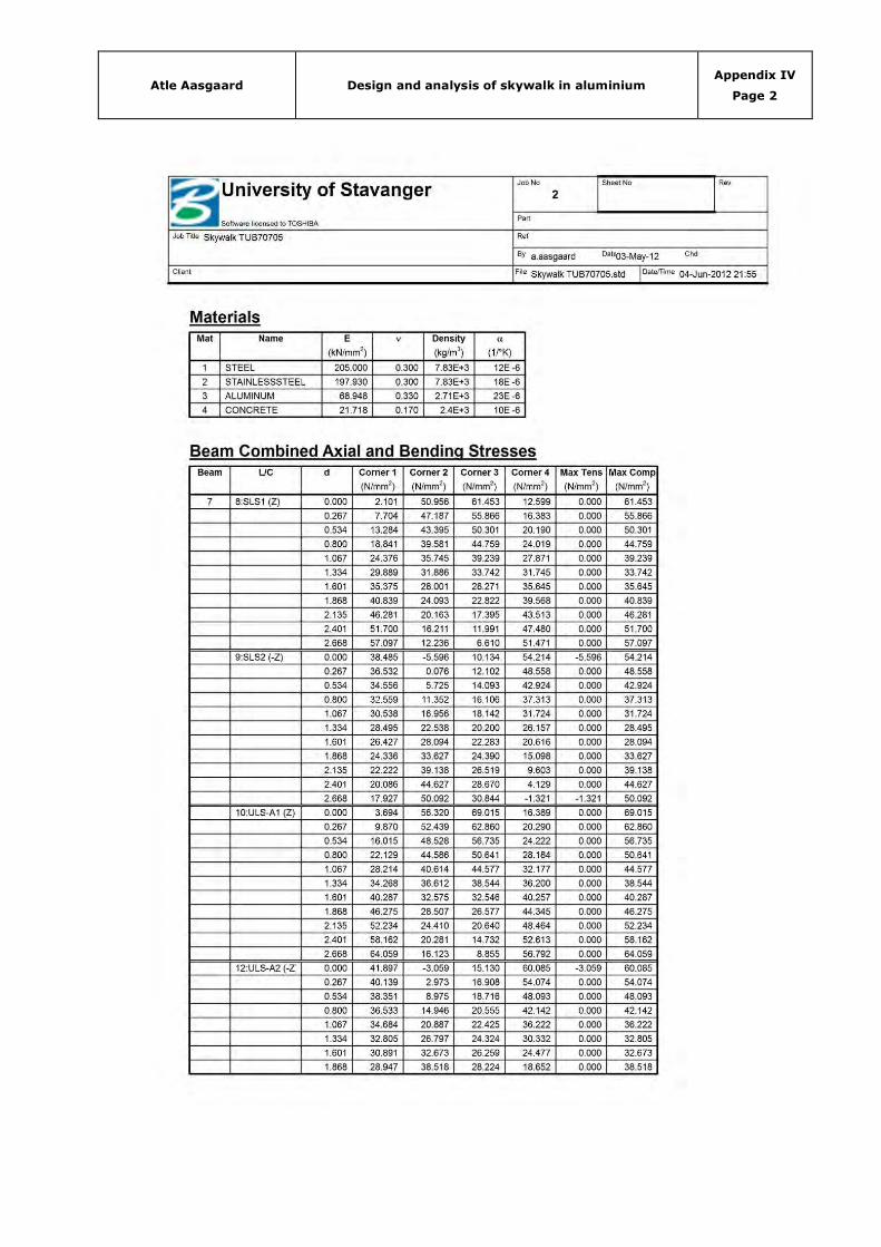
Atle Aasgaard Design and analysis of skywalk in aluminium Appendix IV
Page 2

Atle Aasgaard Design and analysis of skywalk in aluminium Appendix IV
Page 3

Atle Aasgaard Design and analysis of skywalk in aluminium Appendix IV
Page 4
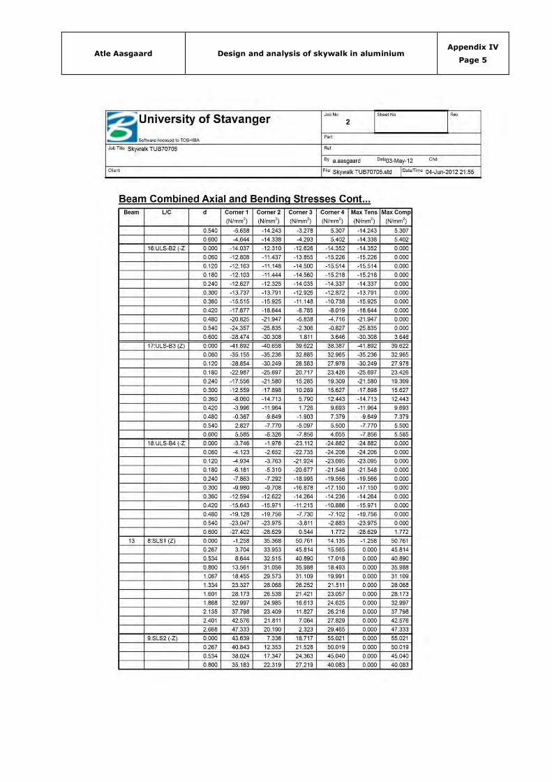
Atle Aasgaard Design and analysis of skywalk in aluminium Appendix IV
Page 5

Atle Aasgaard Design and analysis of skywalk in aluminium Appendix IV
Page 6

Atle Aasgaard Design and analysis of skywalk in aluminium Appendix IV
Page 7

Atle Aasgaard Design and analysis of skywalk in aluminium Appendix IV
Page 8

Atle Aasgaard Design and analysis of skywalk in aluminium Appendix IV
Page 9

Atle Aasgaard Design and analysis of skywalk in aluminium Appendix IV
Page 10

Atle Aasgaard Design and analysis of skywalk in aluminium Appendix IV
Page 11

Atle Aasgaard Design and analysis of skywalk in aluminium Appendix IV
Page 12
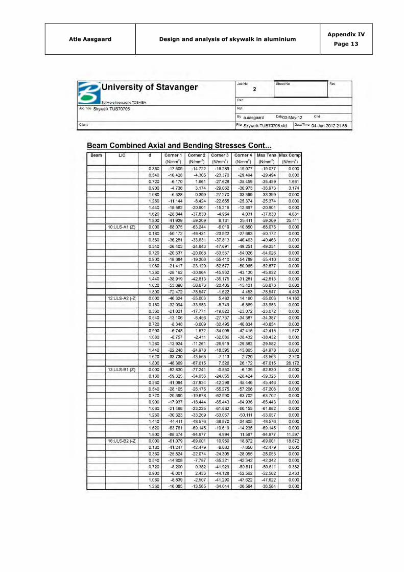
Atle Aasgaard Design and analysis of skywalk in aluminium Appendix IV
Page 13

Atle Aasgaard Design and analysis of skywalk in aluminium Appendix IV
Page 14

Atle Aasgaard Design and analysis of skywalk in aluminium Appendix IV
Page 15

Atle Aasgaard Design and analysis of skywalk in aluminium Appendix IV
Page 16

Atle Aasgaard Design and analysis of skywalk in aluminium Appendix IV
Page 17

Atle Aasgaard Design and analysis of skywalk in aluminium Appendix IV
Page 18

Atle Aasgaard Design and analysis of skywalk in aluminium Appendix IV
Page 19
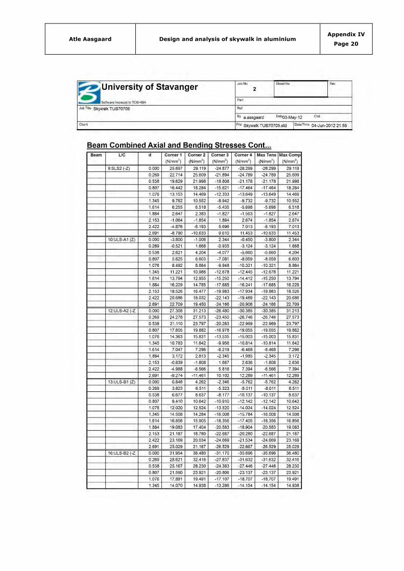
Atle Aasgaard Design and analysis of skywalk in aluminium Appendix IV
Page 20
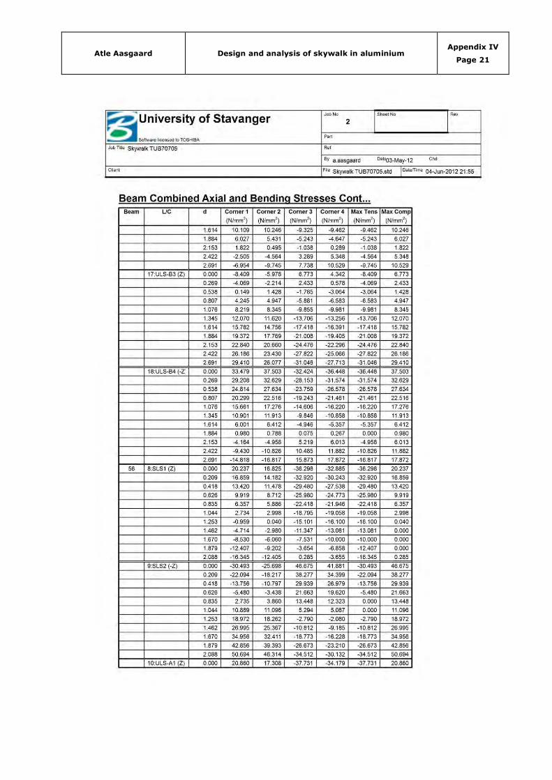
Atle Aasgaard Design and analysis of skywalk in aluminium Appendix IV
Page 21

Atle Aasgaard Design and analysis of skywalk in aluminium Appendix IV
Page 22

Atle Aasgaard Design and analysis of skywalk in aluminium Appendix IV
Page 23

Atle Aasgaard Design and analysis of skywalk in aluminium Appendix IV
Page 24

Atle Aasgaard Design and analysis of skywalk in aluminium Appendix IV
Page 25
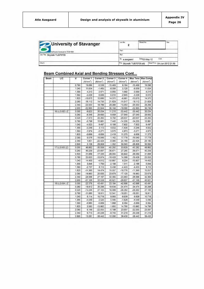
Atle Aasgaard Design and analysis of skywalk in aluminium Appendix IV
Page 26
Atle Aasgaard Design and analysis of skywalk in aluminium Appendix V
Page 0
APPENDIX V – LOCAL CHECK CAST JOINTS
(3 Pages to follow)
Title Pages
Local check cast joints 3

Atle Aasgaard Design and analysis of skywalk in aluminium Appendix V
Page 1
NODE 1
Beam End LC Stresses UF
13 2 18 68.734 0.315
14 1 18 84.677 0.388
15 1 18 -37.030 0.170
56 1 18 66.796 0.306
70 1 18 50.218 0.230
UFz = 0.388 => UFmax UFy = 0.315 => UFmed UFx = 0.306 => UFmin
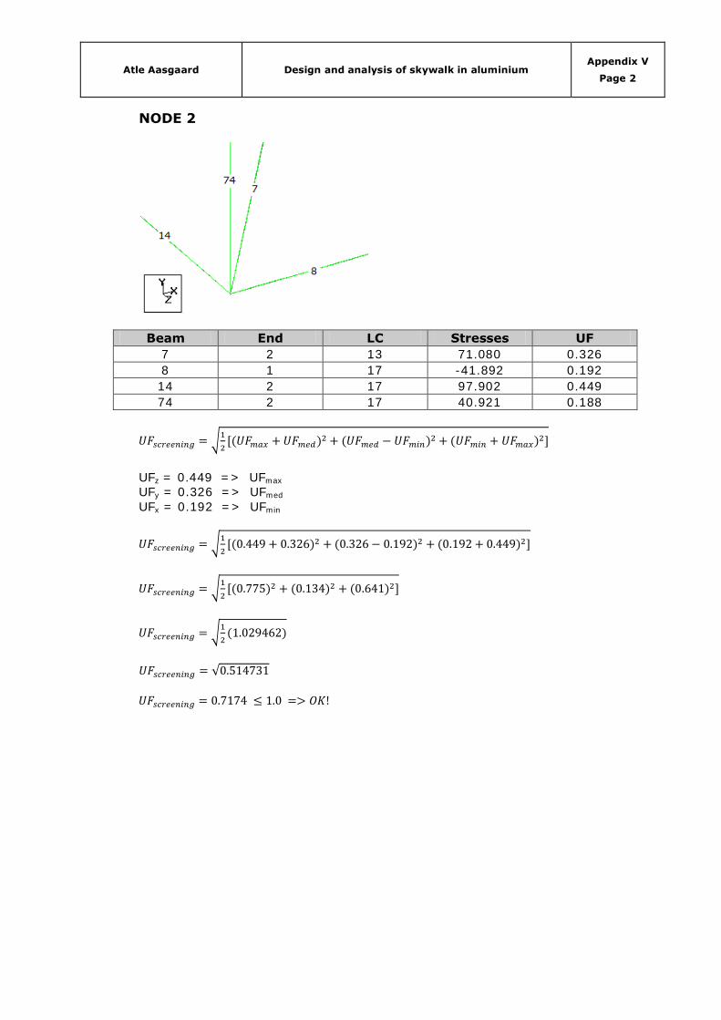
Atle Aasgaard Design and analysis of skywalk in aluminium Appendix V
Page 2
NODE 2
Beam End LC Stresses UF
7 2 13 71.080 0.326
8 1 17 -41.892 0.192
14 2 17 97.902 0.449
74 2 17 40.921 0.188
UFz = 0.449 => UFmax UFy = 0.326 => UFmed UFx = 0.192 => UFmin
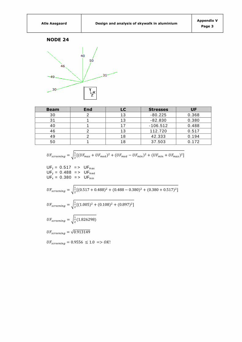
Atle Aasgaard Design and analysis of skywalk in aluminium Appendix V
Page 3
NODE 24
Beam End LC Stresses UF
30 2 13 -80.225 0.368
31 1 13 -82.830 0.380
40 1 17 -106.512 0.488
46 2 13 112.720 0.517
49 2 18 42.333 0.194
50 1 18 37.503 0.172
UFz = 0.517 => UFmax UFy = 0.488 => UFmed UFx = 0.380 => UFmin
Atle Aasgaard Design and analysis of skywalk in aluminium Appendix VI
Page 0
APPENDIX VI – LOCAL CHECK BOLTED CONNECTIONS
(4 Pages to follow)
Title Pages
Local check bolted connections 4
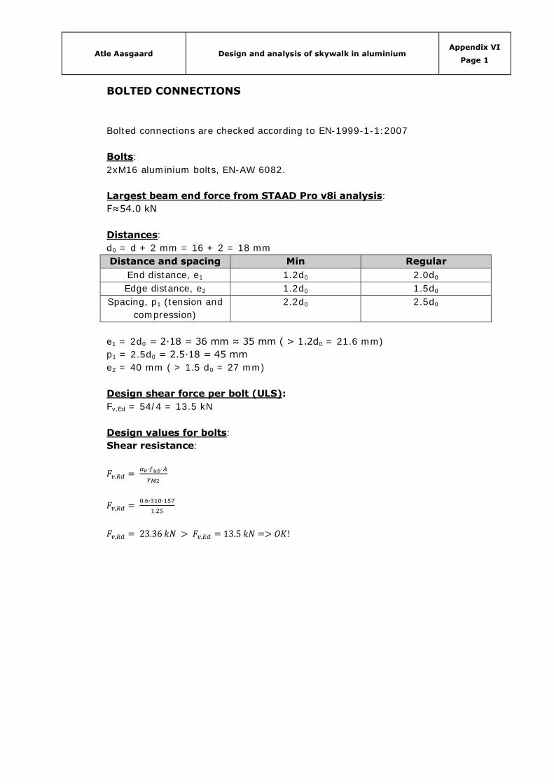
Atle Aasgaard Design and analysis of skywalk in aluminium Appendix VI
Page 1
BOLTED CONNECTIONS
Bolted connections are checked according to EN-1999-1-1:2007
Bolts:
2xM16 aluminium bolts, EN-AW 6082.
Largest beam end force from STAAD Pro v8i analysis:
F≈54.0 kN
Distances:
d0 = d + 2 mm = 16 + 2 = 18 mm
Distance and spacing Min Regular
End distance, e1 1.2d0 2.0d0
Edge distance, e2 1.2d0 1.5d0
Spacing, p1 (tension and
compression)
2.2d0 2.5d0
e1 = 2d0 = 2∙18 = 36 mm ≈ 35 mm ( > 1.2d0 = 21.6 mm)
p1 = 2.5d0 = 2.5∙18 = 45 mm
e2 = 40 mm ( > 1.5 d0 = 27 mm)
Design shear force per bolt (ULS):
Fv,Ed = 54/4 = 13.5 kN
Design values for bolts:
Shear resistance:
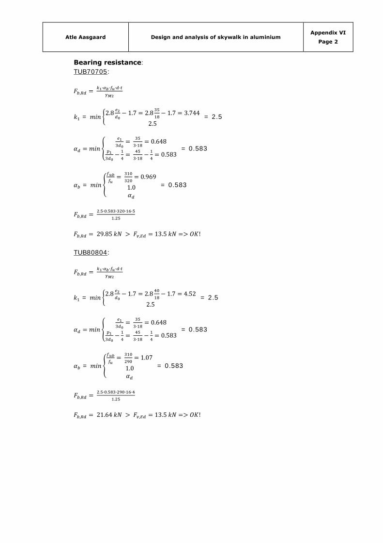
Atle Aasgaard Design and analysis of skywalk in aluminium Appendix VI
Page 2
Bearing resistance:
TUB70705:
=
= 2.5
= 0.583
=
= 0.583
TUB80804:
=
= 2.5
= 0.583
=
= 0.583

Atle Aasgaard Design and analysis of skywalk in aluminium Appendix VI
Page 3
Control of parent material:
TUB70705:
TUB80804:
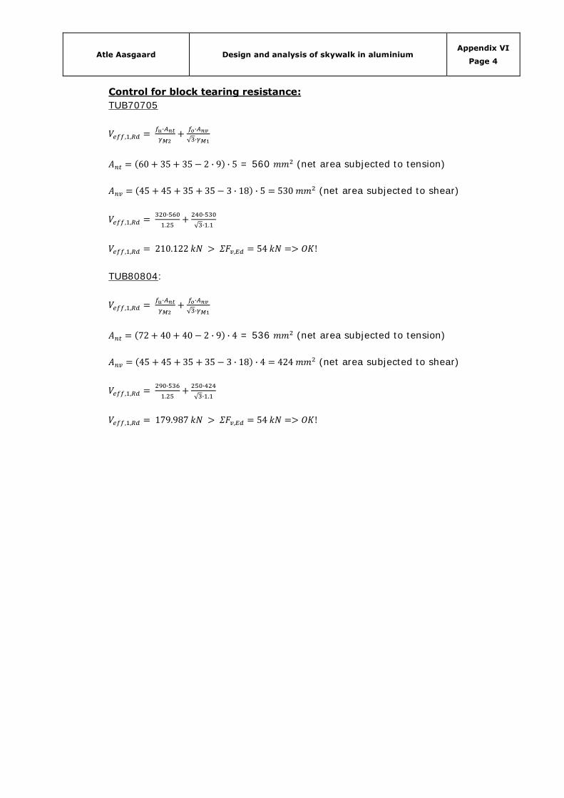
Atle Aasgaard Design and analysis of skywalk in aluminium Appendix VI
Page 4
Control for block tearing resistance:
TUB70705
= 560 (net area subjected to tension)
(net area subjected to shear)
TUB80804:
= 536 (net area subjected to tension)
(net area subjected to shear)

Atle Aasgaard Design and analysis of skywalk in aluminium Appendix VII
APPENDIX VII – DRAWINGS
(2 Pages to follow)
Title Pages
Skywalk 1
Details 1
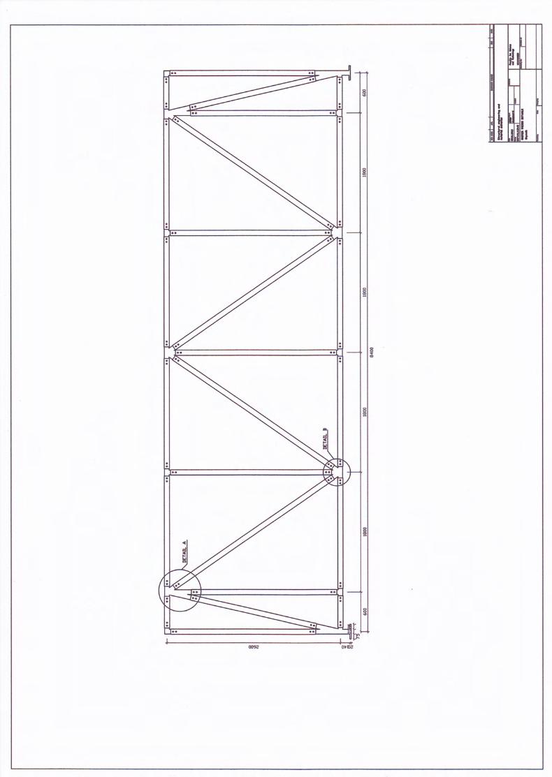

<c
JH
FlrJF
Fqz=Ji?x
t-- NuxtrrRbluta?eHu,zLJ
=Htrl(A,-zHc3-)Fu,(J
l/te , .-:-
) ræoq.al
Related Documents