MASTER THESIS TITLE: Research on path establishment methods performance in SDN-based networks MASTER DEGREE: Master of Science in Telecommunication Engineering & Management AUTHOR: David José Quiroz Martiña DIRECTOR: Cristina Cervelló-Pastor DATE: November, 16th 2015

Welcome message from author
This document is posted to help you gain knowledge. Please leave a comment to let me know what you think about it! Share it to your friends and learn new things together.
Transcript

MASTER THESIS
TITLE: Research on path establishment methods performance in SDN-based networks MASTER DEGREE: Master of Science in Telecommunication Engineering & Management AUTHOR: David José Quiroz Martiña DIRECTOR: Cristina Cervelló-Pastor DATE: November, 16th 2015

TITLE: Investigación en el rendimiento de métodos de establecimiento de rutas en redes basadas en SDN. MASTER DEGREE: Master of Science in Telecommunication Engineering & Management AUTHOR: David José Quiroz Martiña DIRECTOR: Cristina Cervelló-Pastor DATE: 16 de Noviembre del 2015
Overview
Este proyecto tiene como objetivo la evaluación de métodos seleccionados de establecimiento de rutas adaptados a SDN. Se han realizado varios estudios y experimentaciones incluyendo la instalación de un escenario de pruebas de Segment Routing y Proactive Forwarding, la observación de su interoperabilidad con el protocolo OpenFlow, su comportamiento en el manejo del tráfico, su desempeño frente a eventos de la red, y sus efectos sobre el tiempo de respuesta del controlador SDN. El objetivo principal es la investigación sobre la influencia de los métodos de establecimiento de rutas hacia el rendimiento del controlador SDN, que pueden o no, tener un efecto sobre la capacidad de mantener el tráfico durante los cambios controlados e inesperados en la red.

TITLE: Research on path establishment methods performance in SDN-based networks MASTER DEGREE: Master of Science in Telecommunication Engineering & Management AUTHOR: David José Quiroz Martiña DIRECTOR: Cristina Cervelló-Pastor DATE: November, 16th 2015
Overview
This project aims for the assessment of selected path establishment methods adapted to SDN. Several studies and experimentations are performed including the installation of a Segment Routing and Proactive Forwarding test scenario, the observation of their interoperability with the OpenFlow protocol, their behavior in traffic handling, their performance in front of network events, and their effects on the SDN controller’s time response. The main goal is to research about the influence of path establishment methods towards the SDN controller performance, which may or may not have an effect over the ability to sustain traffic during controlled and unexpected changes in the network.

CONTENT INTRODUCTION ................................................................................................ 1
CHAPTER 1. SOFTWARE DEFINED NETWORKING AND OPENFLOW ..... 3
1.1 Software Defined Networking (SDN) .................................................. 3
1.1.1 Application layer .............................................................................. 4
1.1.2 Control layer ..................................................................................... 4
1.1.3 Infrastructure layer ........................................................................... 4
1.2 OpenFlow ................................................................................................ 5
1.2.1 Flow tables ........................................................................................ 6
1.2.2 Group tables ..................................................................................... 8
1.2.3 Meter tables .................................................................................... 10
1.2.4 OpenFlow channel ......................................................................... 10
1.2.5 OpenFlow switch ............................................................................ 12
1.2.6 Openflow versions ......................................................................... 14
CHAPTER 2. PATH ESTABLISHMENT METHODS .................................... 15
2.1 Routing fundamentals .......................................................................... 15
2.1.1 Shortest path routing ..................................................................... 15
2.1.2 Multipath routing ............................................................................ 15
2.1.3 Source routing ................................................................................ 16
2.2 Network performance standards ......................................................... 16
2.3 Proactive Forwarding (PF) ................................................................... 18
2.4 Multiprotocol Label Switching (MPLS) ................................................ 20
2.4.1 MPLS architecture .......................................................................... 20
2.4.2 MPLS topology ............................................................................... 21
2.5 Segment Routing (SR) .......................................................................... 22
2.5.1 Segment list .................................................................................... 23
2.5.2 Segment types ................................................................................ 24
2.5.3 Path computation algorithms ........................................................ 25
CHAPTER 3. TEST TOPOLOGY SETUP .................................................... 26
3.1 Control layer involved elements .......................................................... 27
3.1.1 SDN controller selection ................................................................ 27
3.1.2 Controller’s hardware .................................................................... 29
3.1.3 Controller’s software ..................................................................... 29
3.2 Infrastructure layer involved elements ............................................... 30
3.2.1 Software selection .......................................................................... 30
3.2.2 Hardware selection ........................................................................ 32
3.3 Proactive Forwarding Setup ................................................................ 33
3.4 Segment Routing Setup ....................................................................... 33
3.5 Measurement tools ............................................................................... 34
3.5.1 iPerf ................................................................................................. 34
3.5.2 Multi-Generator (MGEN) ................................................................ 35
3.5.3 Wireshark ........................................................................................ 35
CHAPTER 4. OPERATION IN ONOS CONTROLLERS .............................. 36
4.1 ONOS architecture ................................................................................ 36
4.1.1 ONOS subsystems ......................................................................... 37
4.2 Intent forwarding subsystem ............................................................... 38
4.2.1 Intent subsystem ............................................................................ 38
4.2.2 Topology subsystem ..................................................................... 39
4.2.3 Intent forwarding operation ........................................................... 41
4.3 Segment Routing subsystem .............................................................. 42
4.3.1 Path computation ........................................................................... 43
4.3.2 Group handling ............................................................................... 43
4.3.3 Segment Routing operation .......................................................... 45
4.4 OpenFlow pipeline utilization .............................................................. 46
4.4.1 Intent Forwarding pipeline ............................................................ 46
4.4.2 Segment Routing pipeline ............................................................. 47
CHAPTER 5. EXPERIMENTATION AND RESULTS ................................... 48
5.1 Experimentation process ..................................................................... 48
5.1.1 Network performance measurement ............................................ 49
5.1.2 Response time measurement in front of network events ........... 49
5.1.3 Static path installation time ........................................................... 51
5.1.4 Switch packet forwarding delay measurement............................ 52
5.1.5 Balanced path load scenario ......................................................... 52
5.2 Measurement results ............................................................................ 53
5.2.1 Test topology traffic performance ................................................ 53
5.2.2 Response to network events ......................................................... 53
5.2.3 Response to static path installation ............................................. 54
5.2.4 Switch packet forwarding delay .................................................... 55
5.2.5 Response to network events with balanced path load ............... 55
5.3 Results observations ............................................................................ 56
5.3.1 Packet switching ............................................................................ 57
5.3.2 OpenFlow messaging and method’s operation influence .......... 57
5.3.3 Jitter comparison ........................................................................... 60

CONCLUSIONS ............................................................................................... 61
From the point of view of the test topology ............................................. 62
Future work ................................................................................................. 62
REFERENCES ................................................................................................. 64
ACRONYMS ..................................................................................................... 67
APPENDIX A: OPENFLOW PIPELINE PROCESSING ................................... 69
APPENDIX B: NETWORK TOPOLOGY SCRIPTS .......................................... 71
APPENDIX C: ONOS INTENT FRAMEWORK ................................................. 77
APPENDIX D: SR SUBSYSTEM COMPONENTS ........................................... 78
I. Segment Routing Application ............................................................. 78
II. Configuration Manager ..................................................................... 79
III. Segment Routing Driver ................................................................... 79
OF 1.3 Group Handler ............................................................................. 80
Group Recovery Handler ........................................................................ 80
OF Message Pusher ................................................................................ 81
Driver API ................................................................................................. 81
APPENDIX E: SOFTWARE INSTALLATION ................................................... 82
I. ONOS Blackbird installation ................................................................ 82
Oracle Java 8 JDK installation ............................................................... 82
Apache Karaf 3.0.2 and Maven 3.2.3 installation .................................. 82
Blackbird download and building .......................................................... 83
II. ONOS SPRING-OPEN installation .................................................... 88
CLI installation ........................................................................................ 89
III. Mininet installation ............................................................................ 89
IV. CPqD switch installation .................................................................. 90
APPENDIX F: OPERATION EXAMPLES ......................................................... 92
I. Controller initialization ......................................................................... 92
OpenFlow messages ............................................................................... 92
Flow tables (using a 2 host and 3 routers topology) ............................ 92
II. Link behavior on Segment Routing ................................................. 94
Multipath links ......................................................................................... 95
Link failures ............................................................................................. 95
III. Label sequencing and forwarding operation .................................. 97
APPENDIX G: STATISTIC PROCEDURE ....................................................... 99
I. Average and standard deviation ......................................................... 99
II. Confidence Interval (CI) .................................................................... 99
APPENDIX H: MEASUREMENT TABLES ..................................................... 102
I. Steady state conditions ..................................................................... 102
II. Switch packet forwarding ............................................................... 108
III. Static path installation .................................................................... 113
IV. Network events ................................................................................ 119
V. Balanced path load ......................................................................... 133
APPENDIX I: JITEL 2015 ARTICLE ............................................................... 139
TABLE OF FIGURES
Figure 1.1 - Software Defined Networking Architecture ...................................... 3
Figure 1.2 - OpenFlow Architecture .................................................................... 5
Figure 1.3 - OpenFlow Table .............................................................................. 6
Figure 1.4 - OpenFlow version 1.3 flow table ..................................................... 8
Figure 1.5 - OpenFlow group table ..................................................................... 9
Figure 1.6 - OpenFlow meter table ................................................................... 10
Figure 1.7 - Components of an OpenFlow switch ............................................. 13
Figure 1.8 - OpenFlow pipeline ........................................................................ 13
Figure 2.1 - Proactive forwarding model ........................................................... 19
Figure 2.2 - MPLS architecture ......................................................................... 20
Figure 2.3 - MPLS model ................................................................................. 21
Figure 3.1 - General test network topology ...................................................... 26
Figure 3.2 - Proactive Forwarding test topology ............................................... 33
Figure 3.3 - Segment Routing test topology ..................................................... 33
Figure 4.1 - ONOS architecture ........................................................................ 36
Figure 4.2 - ONOS subsystem structure .......................................................... 37
Figure 4.3 – Intent compilation process within the subsystem .......................... 39
Figure 4.4 - Topology subsystem ..................................................................... 40
Figure 4.5 - Segment Routing subsystem ........................................................ 42
Figure 4.6 - Proactive forwarding pipeline utilization ........................................ 47
Figure 4.7 - Segment Routing pipeline utilization ............................................. 47
Figure 5.1 - Traffic generators and Wireshark probes location ......................... 48
Figure 5.2 – Controller’s response time frame .................................................. 50
Figure 5.3 - Segment Routing processing time frame ...................................... 50
Figure 5.4 - Segment Routing path installation time frame ............................... 51
Figure 5.5 - Proactive Forwarding path load topology ...................................... 52
Figure 5.6 - Counters summary CLI output ...................................................... 55
Figure 5.7 - Test results comparison ................................................................ 57
Figure 5.8 - OpenFlow messaging ................................................................... 58
Figure 5.9 - Flows allocation during static path configuration ........................... 59
Figure 5.10 - Path establishment after failures ................................................. 60
Figure 5.11 - Initial conditions VS Network events ........................................... 60

LIST OF TABLES
Table 1.1 - OpenFlow message description ..................................................... 12
Table 1.2 - OpenFlow versions support description ......................................... 14
Table 2.1 - Network performance parameters .................................................. 18
Table 3.1 - SDN controller selection criteria ..................................................... 28
Table 3.2 - ONOS software requirements ........................................................ 29
Table 3.3 - Infrastructure layer compatibility ..................................................... 31
Table 5.1 - Test topology traffic performance ................................................... 53
Table 5.2 - Network event performance ........................................................... 54
Table 5.3 - Static path installation response ..................................................... 54
Table 5.4 - Proactive Forwarding performance with balanced path load .......... 56

Introduction 1
INTRODUCTION Software Defined Networking (SDN) has acquired great acceptance in the networking community. Thus, several developments and advances have been made to introduce new functions and applications that can give more maturity and specialized operations to the system. Some developments include the adaptation of layer 3 (L3) protocols, such as IGP and BGP to support routing methods into the SDN environment. Since the principle of SDN is a centralized control of the network, every operation triggered by these protocols implies processing introduced to the controller and a response time, that may or may not have an impact over the network. Keeping track of the performance during the adaptation of a new path method to SDN, can help developers setting up a margin, to fulfill a balance between the times required to address the processing needs of the path method, and maintaining a lower response time from the controller. The main objective of this research is to conduct a conceptual analysis of path establishment methods that may have a practical application over SDN. It is intended to observe in which manner the working principle of path establishment methods can influence the performance of an SDN controller in terms of time response. For this reason, it was decided to make a comparative study of two path establishment methods: The method to observe (Segment Routing), and a reference method currently used in SDN (Proactive Forwarding). One example of a L3 path establishment method that is being adapted to SDN is Segment Routing. This method constructs an end to end path based on a sequence of nodes and port codes called segments. On the first node, a packet is guided by this sequence of segments. Once the packet passes through each segment, its related segment id (SID) is pulled out of the sequence. This behavior is maintained until the packet arrives to the edge node that connects to the destination. This research conducts a series of measurements that helps to determine the approximated response time that Segment Routing can introduce into an SDN controller during normal operations and during network events. The response times are compared with the performance of the Proactive Forwarding method. This mechanism is a L2 path establishment procedure, traditionally used in SDN to construct paths according to traffic destination addresses, and set up by flows installed on all switches relevant to the path. The response times of this method are used as a reference to visualize any additional time response introduced by Segment Routing, with respect of the controller’s default state where Proactive Forwarding is supported. The second objective of the investigation is to observe the interaction of the path establishment methods with OpenFlow. Both path methods are established by the controller using the OpenFlow protocol as their interface between the control plane and data plane. The actions triggered by both methods are exchanged between the controller and the network devices through OpenFlow messages.

2 Research on path establishment methods performance on SDN-based networks
OpenFlow has been the first protocol used in SDN as the communication interface between the control plane and the forwarding plane, found in network devices such as switches and routers. It is widely used in most of the current SDN controllers to address the dynamic control of network resources according to the needs of today's applications. It uses TCP sessions to carry out instructions given by the SDN controller, and programs the flow tables found in different network devices, to set an OpenFlow pipeline where the forwarding process is carried out by entries found in the flow tables. This research will show that, according to the method applied, the actions triggered by both path methods will determine the way of how the OpenFlow pipeline will be used on the network devices during packet forwarding. The remainder of this work is organized as follows: Chapter 1 describes the fundamental concepts of SDN and OpenFlow, with
more specific information on the second one, to give the reader a wider view about the operation of OpenFlow.
Chapter 2 describes the fundamental concepts of routing, types of routing,
the path establishment methods to study, and the parameters to observe performance and routing metrics.
Chapter 3 describes the network scenario, including the test scenarios and
the involved elements specifications, in which comparison between several options were made.
Chapter 4 describes the specific operation of Proactive Forwarding and
Segment Routing on the selected SDN controller, in which its architecture is explained.
Chapter 5 describes the experimentation process, the results obtained, and
the observations gathered from both methods. Finally, the conclusions of the research will be given, plus some future work
that may follows from this research.
Chapter 1: Software Defined Networking and OpenFlow 3
CHAPTER 1. SOFTWARE DEFINED NETWORKING AND OPENFLOW
Software Defined Networking (SDN) is a solution that departs from the idea of giving a centralized view and management of the network infrastructure, being capable of making traffic decisions depending on the need of applications and services. In order to manage the various network devices to react according to traffic behaviors, a set of protocols were developed to standardize an interface between the centralized element and the network devices. This chapter gives the necessary fundamentals on SDN and OpenFlow architectures to comprehend the later experimentation performed in this research.
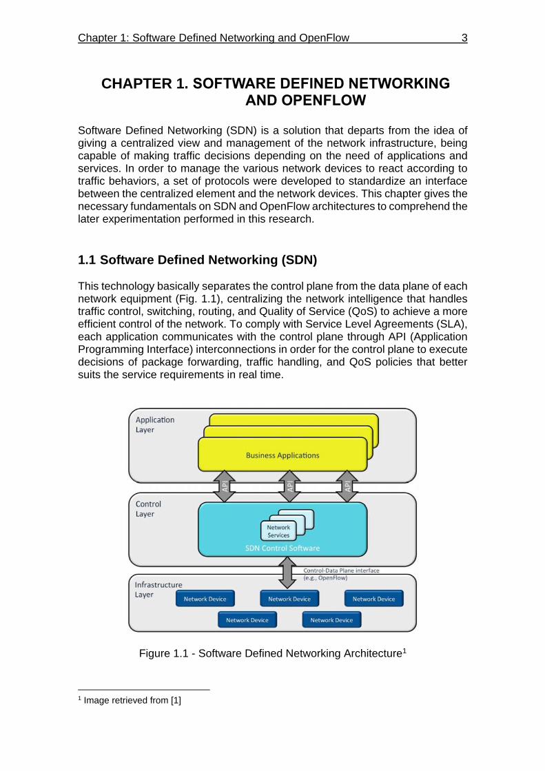
1.1 Software Defined Networking (SDN) This technology basically separates the control plane from the data plane of each network equipment (Fig. 1.1), centralizing the network intelligence that handles traffic control, switching, routing, and Quality of Service (QoS) to achieve a more efficient control of the network. To comply with Service Level Agreements (SLA), each application communicates with the control plane through API (Application Programming Interface) interconnections in order for the control plane to execute decisions of package forwarding, traffic handling, and QoS policies that better suits the service requirements in real time.
Figure 1.1 - Software Defined Networking Architecture1
1 Image retrieved from [1]
4 Research on path establishment methods performance on SDN-based networks
1.1.1 Application layer The application layer represents network applications that interact with the control layer to communicate their requirements for network resources and exercise specific changes in the network, achieving the desired network behavior and QoS for a certain traffic. The application layer communicates with the control layer using application interfaces like North Bound Interface (NBI) or Java API to carry out synchronous and asynchronous messages. They can provide a wide flexibility since different types of traffic can be handled by different network applications separately, using the network infrastructure as a shared resource. For example, network control traffic like LLDP (Link Layer Data Protocol) messages, are treated by a separate network application than normal data traffic like ICMP (Internet Control Message Protocol) messages. The path establishment methods that would be seen in this document, are network applications functioning at this layer.
1.1.2 Control layer The control layer, also known as the Network Operating System (NOS) or SDN controller, is an intermediary between the infrastructure layer and the application layer. It gives applications an abstraction of the network topology, an inventory of the features supported by each network device, network statistics, host tracking information, and packet information. Applications can make decisions accordingly, then the control layer translate those decisions into instructions downloaded to the infrastructure layer, and execute the appropriate network settings for the current traffic. The control layer is conceived to be logically centralized, that means, that the NOS can operate under a cluster of physical servers to share the workload of the system.
1.1.3 Infrastructure layer The infrastructure layer comprises the data plane of the SDN architecture, represented by forwarding devices like switches and routers. They forward packets according to the instructions received by the control layer, like dropping a packet or sending it out through an output interface. The forwarding devices maintains communications with the control layer to keep the system updated on their network status like active ports, adjacent neighbors, supported features, counters information, and event notifications. Logically, the forwarding devices are viewed as a Datapath and identified by a Datapath ID (DPID). This information is used by the SDN controller to address specific instructions to certain devices, like forwarding actions, or to identify each of the network devices in the topology abstraction. The communication channel between the infrastructure layer and control layer is referred as the SouthBound Interface, which is characterized by several
Chapter 1: Software Defined Networking and OpenFlow 5
communication protocols that carry out the interaction between the SDN controller and the Datapaths. The most common SouthBound protocol used is OpenFlow, being accepted by most vendors since it’s been in constant development to work for SouthBound communications and network control.
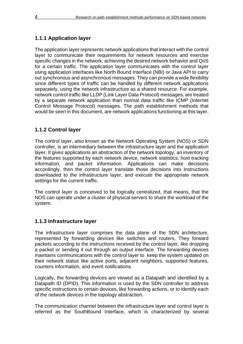
1.2 OpenFlow OpenFlow is a set of protocols and an API that is used in SDN to address the separation of the control plane and data plane, using a standardized protocol between the SDN controller and the network devices for SouthBound communication, forwarding instantiation, and provisioning network programmability from a centralized view via an extensible API. As the communication interface between the control layer and infrastructure layer, it is widely used in most of the current SDN controllers to address the dynamic control of network resources according to the needs of today's traffic. Fig. 1.2, displays the key components of the OpenFlow model:
Switch Control Plane
OpenFlow Controller
LACP RSTP OSPF ...
OpenFlow
Protocol
Figure 1.2 - OpenFlow Architecture2 From the control plane, the OpenFlow API delivers network programmability in which a set of instructions are prepared to perform a forwarding abstraction, using the flow tables of the network elements, and making possible to handle the traffic according to the computation of network applications. Then the OpenFlow protocol establishes a TCP based communication between the control plane and data plane to carry out the OpenFlow messages to the network elements.
2 Image based on [2]
6 Research on path establishment methods performance on SDN-based networks
The OpenFlow protocol is divided in two parts: wire protocol and configuration and management protocol. The wire protocol is the most referenced during the experimentation of this project, and is responsible for establishing control sessions, defining message structures for exchanging flow modifications, collecting statistics, and defining the fundamental function of a switch (ports and tables) [2]. On the other hand, the configuration and management protocol (of-config protocol) allocates physical ports to a controller, and define high availability and actions on controller connection failure [2].
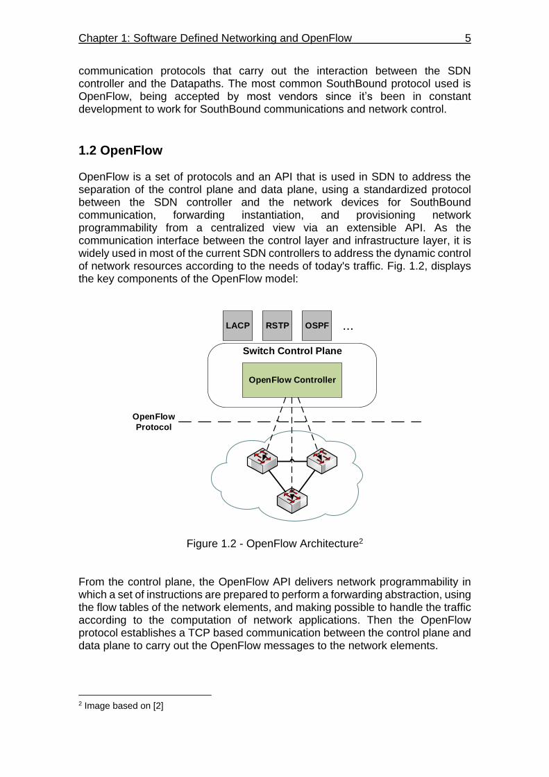
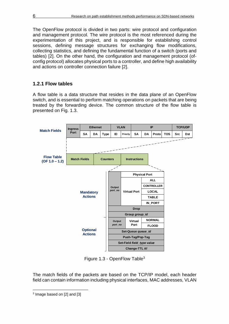
1.2.1 Flow tables A flow table is a data structure that resides in the data plane of an OpenFlow switch, and is essential to perform matching operations on packets that are being treated by the forwarding device. The common structure of the flow table is presented on Fig. 1.3.
Ingress
PortSA DA Type ID Priority SA DA Proto TOS Src Dst
Ethernet IPVLAN TCP/UDP
Match Fields Counters Instructions
Output
port_no
Physical Port
Virtual Port
IN_PORT
ALL
CONTROLLER
LOCAL
TABLE
Drop
Set-Queue queue_id
Push-Tag/Pop-Tag
NORMAL
FLOOD
Output
port_no
Virtual
Port
Match Fields
Flow Table
(OF 1.0 – 1.2)
Mandatory
Actions
Optional
Actions
Group group_id
Set-Field field_type value
Change-TTL ttl
Figure 1.3 - OpenFlow Table3 The match fields of the packets are based on the TCP/IP model, each header field can contain information including physical interfaces, MAC addresses, VLAN
3 Image based on [2] and [3]
Chapter 1: Software Defined Networking and OpenFlow 7
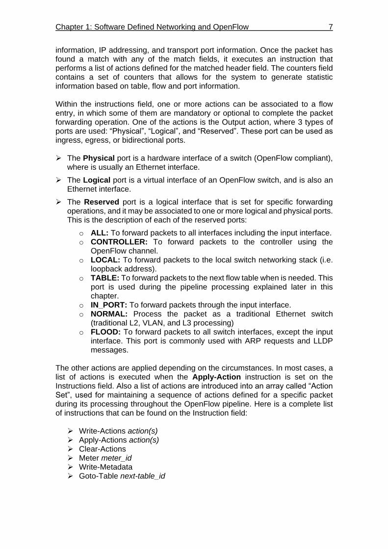
information, IP addressing, and transport port information. Once the packet has found a match with any of the match fields, it executes an instruction that performs a list of actions defined for the matched header field. The counters field contains a set of counters that allows for the system to generate statistic information based on table, flow and port information. Within the instructions field, one or more actions can be associated to a flow entry, in which some of them are mandatory or optional to complete the packet forwarding operation. One of the actions is the Output action, where 3 types of ports are used: “Physical”, “Logical”, and “Reserved”. These port can be used as ingress, egress, or bidirectional ports. The Physical port is a hardware interface of a switch (OpenFlow compliant),
where is usually an Ethernet interface.
The Logical port is a virtual interface of an OpenFlow switch, and is also an Ethernet interface.
The Reserved port is a logical interface that is set for specific forwarding operations, and it may be associated to one or more logical and physical ports. This is the description of each of the reserved ports:
o ALL: To forward packets to all interfaces including the input interface. o CONTROLLER: To forward packets to the controller using the
OpenFlow channel. o LOCAL: To forward packets to the local switch networking stack (i.e.
loopback address). o TABLE: To forward packets to the next flow table when is needed. This
port is used during the pipeline processing explained later in this chapter.
o IN_PORT: To forward packets through the input interface. o NORMAL: Process the packet as a traditional Ethernet switch
(traditional L2, VLAN, and L3 processing) o FLOOD: To forward packets to all switch interfaces, except the input
interface. This port is commonly used with ARP requests and LLDP messages.
The other actions are applied depending on the circumstances. In most cases, a list of actions is executed when the Apply-Action instruction is set on the Instructions field. Also a list of actions are introduced into an array called “Action Set”, used for maintaining a sequence of actions defined for a specific packet during its processing throughout the OpenFlow pipeline. Here is a complete list of instructions that can be found on the Instruction field:
Write-Actions action(s) Apply-Actions action(s) Clear-Actions Meter meter_id Write-Metadata Goto-Table next-table_id

8 Research on path establishment methods performance on SDN-based networks
The structure of the flow table has been maintained on later versions of OpenFlow until version 1.3, where 4 additional fields were added to the flow table (see Fig. 1.4). These fields are identified as: Priority, Timeouts, Cookie, and Flags.
Match Fields Priority CountersFlow Table
(OF 1.3)Instructions Timeouts Cookie Flags
Figure 1.4 - OpenFlow version 1.3 flow table The Priority field identifies which flow entry with the same match field has
precedence to be executed. An example of this situation is when a packet has different paths to get to the same destination, in which the shortest path is commonly assigned with the higher priority.
The Timeouts field indicates the maximum amount of time or idle time before
the flow entry is expired by the switch. This avoids the problem for the switch to maintain large amount of flow entries in memory, which requires high levels of memory and processing resources that only robust and expensive hardware can provide.
The Cookie field is a data value chosen by the controller to filter flow entries
affected by the flow statistics (counters), flow modification, and flow deletion requests. This field is not used during packet processing, but to depurate the flow entries in the table.
The Flags field alters the way of how flow entries are managed, triggering
specific OpenFlow messages to the controller notifying the action taken on a particular flow entry
1.2.2 Group tables Supported since OpenFlow version 1.1, the group tables are means to support packet replication, that is, to support the forwarding of one packet to different ports for different purposes. Normally, the FLOOD action on flow tables allows the forwarding of one packet to multiple ports, but it is limited to emulate the behavior of only certain protocols like LLDP. With the group tables on the other hand, it is allowed a more flexible port grouping for different actions, like assembling a number of ports into an output port set to support multicasting, multipath, and fast failover. Like on the flow tables, the group table contains group entries (see Fig. 1.5) to match the incoming packet to the appropriate forwarding operation. Each group entry is identified by a group identifier given in integer values. Several counters are used to maintain the statistic of the packets treated by the group entry, similar to the counters field found in the flow tables. The forwarding instructions are handled by Action Buckets, in which a packet can be forwarded through a single or multiple ports (1 or more Action Buckets within a group entry), or to another

Chapter 1: Software Defined Networking and OpenFlow 9
group entry (this action is a key component of one of the path establishment methods to be described later in this research).
Group
IdentifierGroup Type Counters
Group Table
(OF 1.1 – 1.5)Action
Buckets
Indirect
All
Select
Fast Failover
Required
Optional
Figure 1.5 - OpenFlow group table There are 4 types of group entries in which 2 of them are required, and the rest are optional: The Indirect type executes one defined bucket in a group. This allows for
multiple flows or group entries to point to a common group identifier. With this group type, an OpenFlow switch can emulate a L3 behavior like pointing to a next hop for IP forwarding.
The All type executes all buckets that are present within a group. The packet is cloned for each bucket and sent to the output interface related to each bucket. With this group type, an OpenFlow switch can emulate multicast and broadcast forwarding.
The Select type executes one bucket of a set of buckets within a group. The
bucket is selected based on a switch-computed selection algorithm like a hash function or simple round robin, rotating the use of each bucket for every incoming packet to achieve equal load sharing on the output interfaces related to the buckets. With this group type, an OpenFlow switch can emulate ECMP operations to load balance the traffic among its interfaces.
The Fast Failover type executes the first live bucket within a group. The
liveness of a bucket depends on the state of the interface and/or group entry associated to the bucket. When an interface fails for some reason, the bucket goes down, and the group entry looks for the next live bucket to send the traffic. With this group type, an OpenFlow switch can emulate fast failover to backup links without consulting the SDN controller.

10 Research on path establishment methods performance on SDN-based networks
1.2.3 Meter tables Since OpenFlow 1.3, the protocol introduces the capability of implementing several simple QoS operations like rate-limiting, or more complex like DiffServ (Differentiated Services). The meter table consists on a set of meter entries (see Fig. 1.6) that defines meters on per-flow basis. They measure the rate of packets associated to a specified meter, enabling rate control on the packets. The meters are associated with flow entries, in which each of the flow entries can specify a meter within its instruction field to execute rate control on incoming packets.
Meter
IdentifierMeter Bands Counters
Meter Table
(OF 1.3 – 1.5)
Band Type Rate Burst Counters Type Specific ArgumentsMeter Bands
Figure 1.6 - OpenFlow meter table The meter identifier is a 32 bit integer value that uniquely identifies the meter entry, the counters are the same used in flow and group tables and they are updated for every processed packet, and the meter bands are the set of instructions that specifies the rate of the band and the way to process the packet. The meter bands are subdivided into the following fields: The Band Type field, which defines the way of how packets are processed.
There are 2 band types available and they are all optional. o Drop: discard the packet based on a rate limiter band. o Dscp remark: Increase the drop priority of the DSCP field in the IP
header of the packet. It may define a DiffServ Policer. The Rate field, which selects the meter band, and specifies the lowest rate
applicable for the meter band. The Burst field, which specifies the granularity of the meter band. The Counters field, which is the same type of counters as in the main table,
but they are updated when a meter band process a packet. The Type Specific Arguments field, which allocates optional arguments of
some band types.
1.2.4 OpenFlow channel According to the OpenFlow 1.3 specifications [3], the OF channel represents a logical interconnection between OpenFlow switches and an OpenFlow controller.
Chapter 1: Software Defined Networking and OpenFlow 11
By means of this interconnection the controller configures and manage the switch for network configuration and packet forwarding, and receives events from the switches to identify network state and failures. A switch may support one or multiple OpenFlow channels for shared management between several controllers (i.e. when a switch is managed by a controller cluster). The communication is handled through a messaging structure defined by the OpenFlow protocol for SouthBound interconnection. It is normally encrypted using TLS, but it can run directly through TCP without encryption.
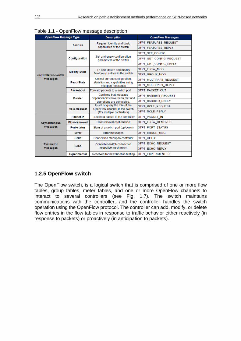
1.2.4.1 OpenFlow messages There are 3 message types supported by OpenFlow: “controller-to-switch”, “asynchronous”, and “symmetric” (see Table 1.1 for detailed message description of the message types). Controller-to-switch messages are initialized by the controller, in which
some of them may require a response from the switch. It monitors and manage the behavior of the switch.
Asynchronous messages are initialized by the switch to send update
messages to the controller, which contains information regarding network events and changes on the switch state.
Symmetric messages can be initialized by either the controller or the switch,
and sent without being required. They are usually used for OpenFlow devices discovery, and keep alive notifications.
12 Research on path establishment methods performance on SDN-based networks
Table 1.1 - OpenFlow message description
1.2.5 OpenFlow switch The OpenFlow switch, is a logical switch that is comprised of one or more flow tables, group tables, meter tables, and one or more OpenFlow channels to interact to several controllers (see Fig. 1.7). The switch maintains communications with the controller, and the controller handles the switch operation using the OpenFlow protocol. The controller can add, modify, or delete flow entries in the flow tables in response to traffic behavior either reactively (in response to packets) or proactively (in anticipation to packets).

Chapter 1: Software Defined Networking and OpenFlow 13
Figure 1.7 - Components of an OpenFlow switch4 As explained previously, each flow table is comprised of flow entries that the incoming packets will match according to the network information they carry, but the table lookup has to be done in order for the packets to be processed in a proper sequence (most packets may need to be processed by more than one flow entry that can be in separate flow tables). Therefore, OpenFlow establishes a linear sequence of flow tables known as the OpenFlow Pipeline (see Fig. 1.8), in which the packets will pass through different tables according to the match fields and the instructions found in the first flow entry.
Figure 1.8 - OpenFlow pipeline5 The flow tables are sequentially numbered starting at “0”, in which the incoming packets are first processed by this flow table. Then, depending on the outcome of the instructions in the flow entry of the first flow table, the packet can be forwarded to the next table (Table 1) and so on. Packets can only go forward through the pipeline, never backwards, due to the fact that the table processing the packet can only send it to a table of higher value than its own. On the other hand, a packet may be processed by only one table, and then be forwarded to an
4 Image retrieved from [3] 5 Image retrieved from [3]
14 Research on path establishment methods performance on SDN-based networks
output port, to the controller, or dropped without passing through the rest of the pipeline (depending on the instructions found in the matched flow entry). During its processing through the pipeline, the packets will carry information of the metadata (register value to carry additional information between tables) and the action set, which can be modified when they are processed by a table using the Write-Action or Clear-Action instructions on the Instruction field. At the final table the actions within the action set are executed (Detailed diagrams about the pipeline and matching process can be found on Appendix A). Here is the order of action execution within the action set:
1. Copy TTL inwards 2. Pop (Apply all tag pop to the packet) 3. Push-MPLS (MPLS tag) 4. Push-PBB (PBB tag) 5. Push VLAN (VLAN tag) 6. Copy TTL outwards 7. Decrement TTL 8. Set (Apply all Set-Field actions) 9. QoS (Apply all QoS actions) 10. Group (Apply actions of the related group bucket into the order specified
by the list) 11. Output (Forward the packet to the port specified by the Output action)
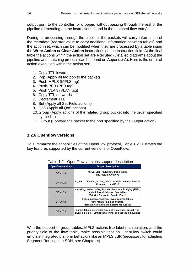
1.2.6 Openflow versions To summarize the capabilities of the OpenFlow protocol, Table 1.2 illustrates the key features supported by the current versions of OpenFlow.
Table 1.2 - OpenFlow versions support description
With the support of group tables, MPLS actions like label manipulation, and the priority field of the flow table, make possible that an OpenFlow switch could emulate integrated platform behaviors like an MPLS LSR (necessary for adapting Segment Routing into SDN, see Chapter 4).
Chapter 2: Path establishment methods 15
CHAPTER 2. PATH ESTABLISHMENT METHODS This research defines path establishment methods as a general term to describe L2 and L3 routing techniques. Although routing traditionally implies L3 routing protocols, in SDN would also include L2 bridging since both achieves a common goal, to establish an end-to-end path in a network using path computation algorithms. The difference, is that L3 methods are IP-based routing, and L2 methods are MAC-based bridging. This chapter will introduce some fundamentals about routing and type of routing, the current standards in network performance, and the working principle of Proactive Forwarding, MPLS, and Segment Routing.
2.1 Routing fundamentals Routing can be defined as “the act of moving information across and internetwork from a source to a destination” (Cisco Systems Inc., 1998). An ideal routing process has to address certain goals, in which the result would have to represent the most efficient use of the network. Some of these goals includes the ability to choose optimal paths, to compute paths that has an efficient use of the bandwidth, and to exhibit high convergence after network changes. There are several types of routing that tries to approach these conditions like: Shortest Path routing, Multipath routing, and Source routing.
2.1.1 Shortest path routing Shortest path routing defines best routes according to the cost of links that forms each path. The costs of each link in the network are determined by measurement standards called metrics, which usually are latency, link bandwidth, hop counts in the path, and sometimes the operational expenditures of each link (i.e. the use of rented link platforms like radio bridges). These metrics are related by the computation of a cost function that results on the total costs to be assigned for each link. With the link costs assigned, shortest path protocols can use different routing algorithms to compute the best path between a pair of nodes in the network, and pick random paths if there is more than one best path of equal cost between the pair of nodes. Some of the most referred routing algorithms are Dijkstra’s and Bellman-Ford algorithms, used for Link-State and Distance-Vector based protocols, respectively.
2.1.2 Multipath routing Multipath routing defines multiple alternative paths throughout the network in which the traffic can be forwarded to get to a common destination, increasing the available bandwidth, and improving fault tolerance and security. Investigations

16 Research on path establishment methods performance on SDN-based networks
suggest that the benefits of multipath routing are addressed to improve end-to-end reliability, congested paths avoidance, and adaptation to application performance requirements [5]. One of several strategies used in multipath routing is Equal-cost multi-path (ECMP).
2.1.2.1 Equal-cost multi-path (ECMP) ECMP is based on delivering multipath routing throughout several paths when they offers the same cost in arriving to the destination. On this scenario, there is no preferable path to follow since each of them offers the same performance, besides, the multiple paths to choose from are most probably the best paths computed by shortest path routing. Therefore, what ECMP does, is to share the traffic flow among the available links using either random or round-robin (cyclic order of links) selection. This allows for the network to load-balance the traffic throughout sections where redundant links, or complete redundant paths are available, achieving fault tolerance, high availability, and increased throughput. ECMP is more generally used as an additional feature of several routing protocols like Open Shortest Path First (OSPF), and Intermediate System-to-Intermediate System (IS-IS), which are shortest-path based routing protocols.
2.1.3 Source routing Source routing is a type of routing that allows a source network device to process and define a partial or complete route through the network for packet forwarding, instead of being processed by every intermediate device in the network. The entire path of each packet is known when they are injected into the network, being the routing information added to the packet header to avoid local routing decisions at each hop [6]. In basic terms, the source routing operation is based on a list of intermediate devices and links within the packet header at the source forwarding device, in which the list represents an ordered sequence of hops where the packet will traverse until it reaches the destination. Within this sequence or route, source routing can allow for concurrent use of multiple paths in the network, being the sender device capable to choose different routes on a per-packet basis. Some investigations points out that for SDN environments, source routing can be an alternative method for packet forwarding than traditional OpenFlow instantiation [7].
2.2 Network performance standards From the point of view of the customer, network performance can be a little subjective, since it is a measurement of the service quality perceived by him/her (better known as Quality of Experience, or QoE). From this perspective, network performance parameters have been observed for values that limits the customer perception between optimal and degraded communications. These parameters

Chapter 2: Path establishment methods 17
are used to determine the QoS levels to be assigned to each type of traffic, and the reference to follow for service level agreements (SLAs) between network service providers and customers. The main parameters used to measure network performance are: Bandwidth, Throughput, Delay, Jitter, and Packet Loss. The Bandwidth in computer networks is the available bitrate or channel
capacity of a communications link expressed in bits per second (bps). It can also refers to the transmitted information capacity in bits per second.
The Throughput in computer networks is the transmitted or consumed
bandwidth in the network expressed in bits per second. When a traffic transmitted at a line rate speed is measured, the maximum bandwidth received over an end-to-end communication is the throughput that the network delivers for that communication.
The Delay is the time interval between the transmission and reception of a
packet. There are 2 types of delays in computer networks: o One-way delay: Time interval of a packet to traverse the network from
a source to a destination. It is difficult to measure since both end points (source and destination), have to be synchronized in time through a reference clock, in which its accuracy can be expensive and hard to achieve. This delay is more accurate to measure the response of the network in front of situations like link failures, or to monitor that the network is complying with the stipulated SLA.
o Round Trip Time (RTT): Time interval of a packet to traverse the network from a source to a destination and return back to the source. RTT is most commonly used since is easier to measure from most end devices, but is less accurate to perceive the response of a network in front of failures. This doesn’t mean that One-way delay is RTT/2, since the trip and return delays may not be the same.
The Jitter is the variation of the delay perceived in an end-to-end
communication. From the point of view of the transmission, packets traversing at a fixed bitrate denotes a periodic transmission, in which the jitter represents a variation of that periodicity. This parameter, is less desirable in computer networks since it can degrade sensible traffic like voice and video, which depends greatly on real time communications.
The Packet Loss, like the name states, is the amount of packets that have
been lost during transmission over the network, either for errors in the transmission, or for the network capacity to handle the traffic in terms of bandwidth and throughput.
There are all kinds of traffic that can traverse throughout the network, and each of them with their own demands in network performance to guarantee the desired QoS and SLA. To test the network to cover all these demands, is better to focus on the demands of the most critical type of traffic, the voice traffic. Voice communication is the most sensible traffic, because all voice packets have to be sent in real time over the network. If there is considerable delay and jitter, or if there is not enough guaranteed bandwidth, the voice communication degrades

18 Research on path establishment methods performance on SDN-based networks
easily, perceiving gaps in the sound or interruptions. According to several vendors and ITU recommendations, the following table represents the desired parameters to ensure proper network performance for Voice over IP (VoIP) communications.
Table 2.1 - Network performance parameters
Network performance for VoIP
One-way Delay ≤ 150ms
Packet Loss ≤ 1%
Jitter ≤ 30ms
Guaranteed Bandwidth 21Kbps to 320Kbps
The one-way delay limit is specified by the ITU-T G.114 recommendation [8], which is acceptable for most user applications. Even levels of delays up to 400ms can be accepted for several types of traffic, but network providers have to be aware of possible impacts over the transmission quality. There is no direct consent about a standard limit for jitter, but several vendors like Cisco Systems Inc. [9], have developed several testing, and their results suggest that voice communications tends to start degrading on jitter values greater than 30ms. As for guaranteed bandwidth, it is variable for any kind of communication in which providers have to guarantee that the physical link can cover for all desired traffic. For the purpose of this research, the values of network performance for VoIP communications are used as a reference, to compare network performance measurements on the path establishment methods described in Chapter 5.
2.3 Proactive Forwarding (PF) Proactive forwarding is defined in this research as a global term to describe path establishment methods that use OpenFlow proactive instantiation, defining flow rules in L2 switches in anticipation of traffic, and constructing end-to-end paths on an SDN network. Generally on most SDN vendors, proactive forwarding is a shortest path routing type, in which Dijkstra based algorithms are used for path computation. The basic function of proactive forwarding methods, is to establish end-to-end paths using the source and destination MAC addresses, defining flow entries to be added on the flow tables of the switches for pipeline processing. Only the involved switches in the path will receive this update on their flow tables in order to define forwarding actions according to the match field of the flow entries. The SDN controller will start this process once received the first packet, and then in anticipation of the rest of the traffic, the controller downloads all necessary flows to the involved switches to establish the path (see Fig. 2.1).
Chapter 2: Path establishment methods 19
Flows
SDN Controller
1
2
OFPT_PACKET_IN
3
4
First Packet
5Subsequent Packets
3
OFPT_PACKET_OUT
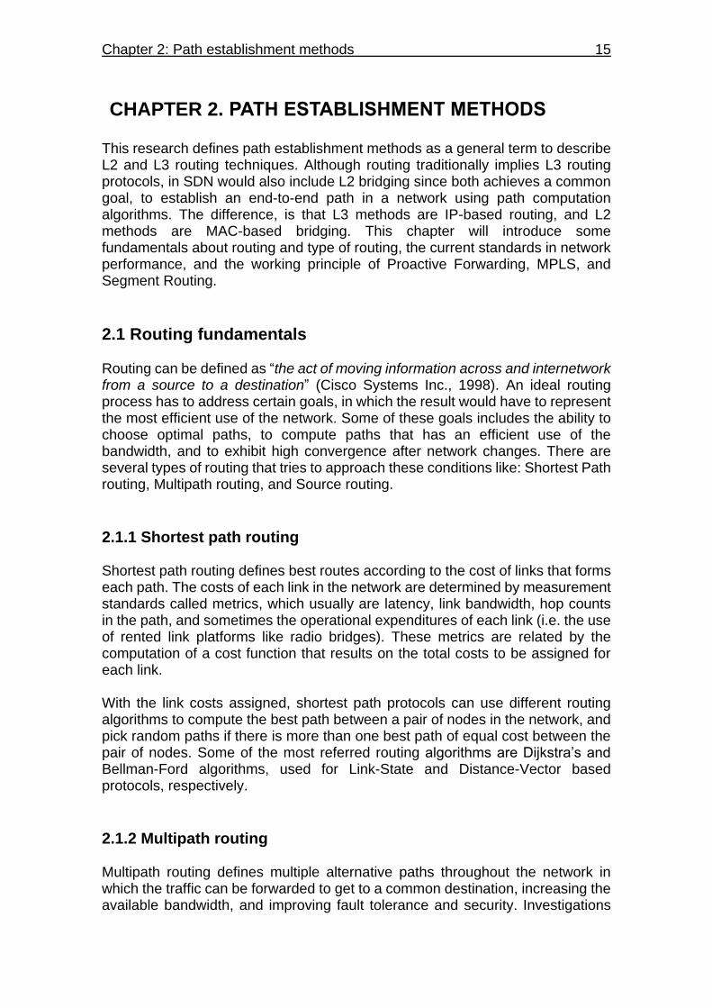
Figure 2.1 - Proactive forwarding model The switch receiving the first packet will not know the route to follow to a destination. When this happens, the switch attaches the packet into an OpenFlow message (OFPT_PACKET_IN) and send it to the controller to consult the route to take for the packet, and subsequent packets with the same destination. Using the MAC address information stored in the packet header, the SDN controller computes the shortest path (least-cost path) to the destination based on metrics like hop count, link bandwidth, and delay. After the path computation, the SDN controller defines the necessary flow instructions and send them to the involved switches in the path, in parallel with an OFPT_PACKET_OUT message to the first switch in response of the OFPT_PACKET_IN message, defining the forwarding action of the first packet. With the flow entries downloaded into the switches flow tables, the end-to-end path is established allowing for subsequent packets with the same source and destination address information, be forwarded throughout the network without consulting the SDN controller. With difference of OpenFlow reactive instantiation, in which flow entries have expiration time for unused paths, proactive instantiation maintains the flow entries, and hence preserves the path indefinitely until there is a change in the physical path. Examples of practical applications of proactive forwarding includes: L2 Switch application or OpenStack network abstraction in OpenDaylight controllers, Intent forwarding application in ONOS controllers, and NOX proactive mode in NOX controllers.

20 Research on path establishment methods performance on SDN-based networks
2.4 Multiprotocol Label Switching (MPLS) MPLS is an architecture that defines a mechanism to perform label switching, in which handles the combination of L2 packet forwarding and L3 routing [11]. It assigns labels to packets for their transportation across packet-based or cell-based networks. Label swapping is the forwarding mechanism used throughout the network, in which data information carry a short and fix-length label that instructs switching nodes how to process and forward the packets along the path.
2.4.1 MPLS architecture The architecture is a distributed system, where each node within the MPLS domain is divided into two main components: the data plane and control plane. The data plane maintains a label-forwarding database (FIB and LFIB tables) to perform the packet forwarding based on the labels carried by the packets. The control plane, creates and maintains label-forwarding information (LIB table) among a group of interconnected nodes. Fig. 2.2 illustrates the basic architecture of an MPLS node.
IP routing table
Forwarding Information Base
(FIB)
IP routing protocols
MPLS IP routing control
Label Forwarding Information Base
(LFIB)
Label Information Base
(LIB)
Control Plane
Data Plane
Label binding
exchange with
other nodes
Routing information
exchange with other
nodes
Incoming IP packets
Incoming labeled packets Outgoing labeled packets
Outgoing IP packets
Figure 2.2 - MPLS architecture6 Every MPLS node runs one or more IP routing protocols to exchange IP routing information between them, making every node an IP router in the control plane. This exchange, allows the nodes to identify the networks attached to each node and determine where to send the packets through the use of labels. The nodes exchange label information, in which they store the mappings of labels assigned by a local node with the labels received from its neighbors into a Label Information Base (LIB). These mappings are distributed within the MPLS domain through the use of the Label-Distribution Protocol (LDP).
6 Image based on [11]
Chapter 2: Path establishment methods 21
During packet forwarding, not all the labels within the LIB table are needed. In this sense a table in the data plane is used (the LFIB table), where it pulls out only the necessary label mapping information from the LIB table, performing the packet forwarding operation of the current traffic for a current established path. The IP routing table is used with the MPLS IP routing control process to build the FIB table, which is an IP forwarding table augmented with labeling information in order to introduce labels to ingress packets or remove labels from egress packets (functionality used in edge nodes), and send them either outside or inside the MPLS domain.
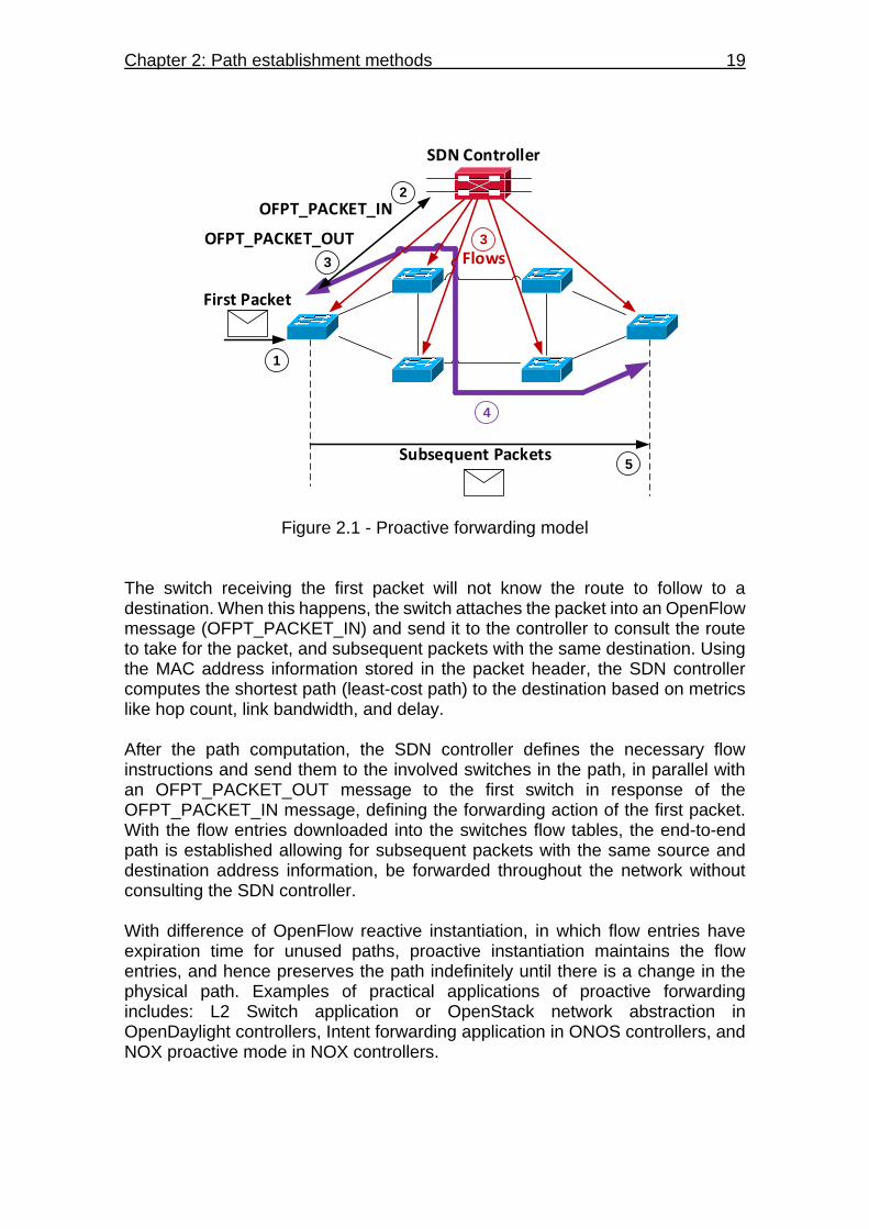
2.4.2 MPLS topology The control and data plane operation in each MPLS node, brings together the traffic forwarding operation of the entire MPLS domain. The following figure, contemplates the MPLS model which constitutes its forwarding operation and topology.
Edge-LSR
LSR LSR
LSRLSR
1
2
5
PUSH
POP
IP Packet
IP Packet L1
3
SWAP
IP Packet L2
4
SWAP
IP Packet L3
PHP
6
IP PacketLSP
Edge-LSR
Figure 2.3 - MPLS model In the MPLS domain, all nodes are designated as Label Switch Router (LSR), in which the edge nodes are commonly identified as Edge-LSR. The difference in operation, is that Edge-LSRs prepend or remove labels from the IP packets by using the FIB table for IP and Label based forwarding. In this manner, the Edge-LSR serves as an intermediary between the MPLS domain and other routing domains like IGP (Interior Gateway Protocols) and EGP (Exterior Gateway Protocols) domains. The rest of the LSR within the MPLS domain, executes only label based forwarding operations like the SWAP action. The ingress IP packets are attached to a label by the Edge-LSR using the PUSH action. Then the Edge-LSR sends the packet to the next hop according to the

22 Research on path establishment methods performance on SDN-based networks
label information, in which the subsequent hops (LSRs) replace label information through the SWAP action for every next hop that the packet traverse. Finally, depending on the configuration made on the nodes, the POP action (removal of the label) can be performed by either the Edge-LSR or by the hop before it, in which the POP action is known as Penultimate Hop Popping (PHP). The entire forwarding process according to the labels information, establishes and end-to-end path within the MPLS domain referred as a Label Switched Path (LSP). Several LSPs can be established by the use of path computation algorithms or manual configuration that can be used for different purposes including VPN routing, traffic engineering, and QoS.
2.5 Segment Routing (SR) Segment Routing is a new source routing method that is being developed by the IETF to be supported on several routing protocols running today. In principle, an intermediate device or SR node, guides the packet through an ordered sequence of instructions called segments [12]. A segment can be any topological or service-based instruction, in which the packet will be treated according to the sequence found on its header (see Fig. 2.2). It can be applied to both MPLS and IPv6 architectures, in which would only require small changes into their forwarding planes.
10081007
1006 1004
1021007104
101
102 103
104
105106
1001 1003
1005
1007104
104
1
2
3
4
5
PUSH
POP
1002
Figure 2.4 - Segment Routing model As described in the general functionality of source routing, segment routing constructs the end-to-end path based on a list of segments that are identified by an integer value called the segment identifier (SID), which also identifies a network element (SR node, group of nodes, SR domain, link, and set of links)

Chapter 2: Path establishment methods 23
that is going to apply the segment instruction. Each segment is executed by the SR node on any incoming packet. Following the above model (Fig. 2.2), the ingress SR node introduces the list of segments into the incoming packet. The list denotes 3 segments or instructions that are going to be executed by nodes 102 and 104. The order of execution goes from top to bottom. Node 102 will receive the packet, execute and pull out the first and second instruction from the list and send the packet through link 1007, nodes 106 and 105 will forward the packet to node 104 without executing the remaining instruction, and node 104 will pull the final segment stored in the stack and forwards the packet to the desired destination. A segment involves actions like forwarding a packet according to shortest path destination, an interface, or an application/service instance. An SID can be an MPLS label, an index value on the MPLS label space, or an IPv6 address, depending of the data plane that segment routing uses.
2.5.1 Segment list An ordered list of SIDs that encodes the topological and service-based source route of the packet. Depending of the data plane used, it could be and MPLS label stack, or a list of IPv6 addresses. In the top of the list lies the active segment, which is the instruction the must be executed by the receiving SR node to process the packet. During the packet transit through the path, the following actions can be executed on the segment list: Push, Next, Continue, and POP. The Push action is executed by an SR node to introduce a segment into the
segment list. The Next action is used when an active segment is completed, defining the
next segment in the list as the active segment. The Continue action, is used when the current active segment is not yet
completed, and maintains its state as an active segment. One example is when an SR node receives a packet with segments that is not up to the node to execute any of them, forwarding the packet to the node that supposed to execute the active segment (i.e. nodes 106 and 105 of Figure 2.2).
The POP action is used at the edge node to remove the final segment from
the segment list, and send the packet to its final destination. In the MPLS data plane, the node previous to the edge node can perform this action (PHP).
2.5.1.1 SR Tunnel Is a segment list specified with abstract constrains (like delay or priority) pushed on a packet to define a route that can be used for traffic engineering, OAM, or FRR reasons. SR tunnels can be configured manually by the operator.
24 Research on path establishment methods performance on SDN-based networks
2.5.2 Segment types Segments can be classified in two categories: local and global segments. The Local segments are the ones that are originated by an individual node
and they are only supported by that node. Examples of these segments are those related to links directly connected to the SR node.
The Global segments are the ones that their related instructions are supported by all SR-capable nodes in the domain [12]. It can be used to identify a group of nodes that can handle a specific instruction, and relate their local SIDs to a global SID.
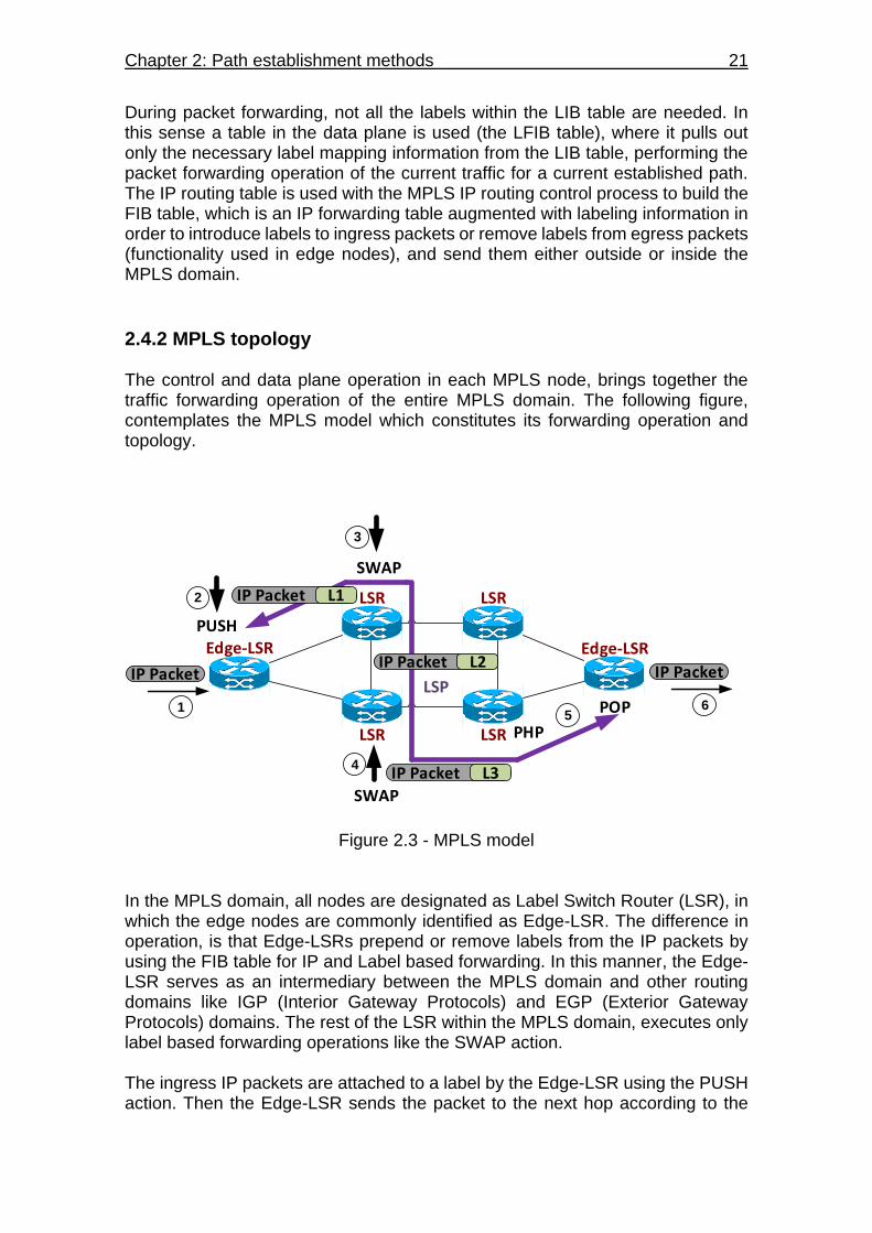
Besides local and global segments, they can also be classified in two types: IGP segments and BGP peering segments. BGP peering segments are out of the scope of this research, so they will not be discussed. The IGP segments are the ones advertised by an SR node for its attached prefixes and adjacencies within a link-state IGP domain, and their classification can be observed on Fig 2.5:
Figure 2.5 - IGP segments classification The IGP-Prefix segments are global segments attached to an IGP-Prefix such as a summarized network addresses that are advertised within the IGP domain. IGP-Anycast and IGP-Node segments are the two types of the described segments, in which Anycast segments identifies a group of nodes by an Anycast SID, and the Node segments identifies a single node using a Node-SID (usually related with the node’s loopback address). The IGP-Adjacency segments are local segments attached to a unidirectional or a set of unidirectional adjacencies, and they are identified using an Adj-SID (adjacency segment identifier). The adjacency is formed by the interconnection

Chapter 2: Path establishment methods 25
of a local node and its neighbor, and it can be advertised throughout the SR domain. When a packet is following the segment list and finds an Adj-SID of a specific node, it means that the action that the node will take for the packet is to forward it through the adjacency (link interface) assigned to the Adj-SID. If there is more than one adjacency assigned to the Adj-SID (set of link interfaces), the node will load balance the traffic through the set of adjacencies. This gives two options of encoding the Adj-SID: to reference the use of protection in the adjacency (IPFRR or MPLS-FRR), and to identify an adjacency as a local segment.
2.5.3 Path computation algorithms There are two routing algorithms defined for segment routing: Shortest Path and Strict Shortest Path. Shortest Path is the default algorithm, in which a packet is forwarded along
the well-known ECMP-aware SPF algorithm. It has the flexibility that an intermediate device can implement a policy-based forwarding action that can override the SPF decision.
Strict Shortest Path works the same as the default shortest path algorithm,
but instructing each intermediate device to ignore any local policy-based forwarding actions overriding the SPF decision.
Prefix-SID advertisement includes a set of flags and an algorithm field, in which associates a given Prefix-SID (Anycast or Node) to either routing algorithms. An ingress node gathers in this way all nodes and adjacencies information from the Prefix-SID advertisements, and the routing algorithm constructs the end-to-end path for any traffic incoming to the SR domain.

26 Research on path establishment methods performance on SDN-based networks
CHAPTER 3. TEST TOPOLOGY SETUP The general idea to measure the behavior of path methods in front of network events, is to provide a scenario where an end-to-end communication is available through multiple paths. A virtual network topology was built to meet these conditions, and is presented on Fig. 3.1. The network topology is contained within 2 physical computers, in which one of them runs an SDN controller, and the other the infrastructure layer. The forwarding plane is comprised of 10 L2 virtual switches interconnected with the SDN controller, using a TCP port per switch-controller connection over a single physical Ethernet link, 2 virtual hosts (h1 and h2) from where the end-to-end communication is taken place, and 12 virtual Ethernet links interconnecting the switches.
S1
S2 S4S3 S5
S6
S7S9S10
h1 h2
SDN Controller
S8
PC 1
PC 2
Ethernet Link
TCP
interconnections
Figure 3.1 - General test network topology The links disposition allows the SDN controller for the computation of 8 possible paths between hosts h1 and h2 as listed below.
1) S1, S2, S3, S4, S5, S6 2) S1, S10, S9, S8, S7, S6 3) S1, S2, S3, S9, S8, S7, S6 4) S1, S2, S3, S4, S8, S7, S6 5) S1, S10, S9, S3, S4, S5, S6 6) S1, S10, S9, S8, S4, S5, S6 7) S1, S2, S3, S9, S8, S4, S5, S6 8) S1, S10, S9, S3, S4, S8, S7, S6
This chapter, describes the main hardware used to build this topology, the measurement tools used for the experimentations, the SDN controllers selected
Chapter 3: Test topology setup 27
for the configuration of path establishment methods, and their setup over the network topology.
3.1 Control layer involved elements The main purpose of using two computers, is to isolate the processing load of the SDN controller under one hardware. This allows to measure the controller’s response to the network without being affected by other mayor processes external to the normal operation of the computer. The same situation applies to the infrastructure layer, in which one computer can dedicates its hardware resources for the data plane processing, and ensure the network performance in terms of packet forwarding as realistic as possible. Therefore, an SDN controller is selected and hence, its related hardware to support its processing demands.
3.1.1 SDN controller selection Since Segment Routing is a relative new method, the main idea in this project was to find a complete adaptation of Segment Routing to SDN. Several controllers were observed, along with their project developments. There were two options for the SDN controller: OpenDaylight and ONOS. OpenDaylight, is a modular and multiprotocol controller infrastructure built
for SDN deployments on multi-vendor networks. It has mayor development effort through a community sponsored by several vendors like Cisco, Brocade, HP, Huawei, Vmware, and Oracle.
ONOS, or Open Network Operating System, is a modular and distributed
core controller infrastructure targeted for service providers and mission-critical networks, with the mission of ensuring high availability, scale-out and performance to the service provider’s network. It has been developed by the Open Networking Lab (ON.Lab) in coordination with service providers like AT&T, and network vendors like Ericsson, Cisco and Huawei.
Since both controllers have full capabilities to manage the Proactive Forwarding method, the selection criteria was based on how the way in handling Segment Routing, allows for more flexibility to implement the test topology and the measurements made in this research. Table 3.1 displays a comparison of both platforms in terms of Segment Routing capabilities, hardware requirements, and compatibility with the test scenario:

28 Research on path establishment methods performance on SDN-based networks
Table 3.1 - SDN controller selection criteria
Based on the characteristics observed, the SDN controller selected for the experimentation was the ONOS controller. There were several factors taken into account, in which the main reasons for selection were the following: The Segment Routing version of ONOS is designed to work over MPLS, in
which previous knowledge of this architecture gave more understanding of the working principle of Segment Routing, and its operation on an SDN network.
The ONOS controller gives more flexibility to build the infrastructure layer,
since it’s capable of configuring OpenFlow switches to emulate L3 routing devices. During the selection, there were no OpenFlow routing devices available to work with OpenDaylight.
The Segment Routing version of ONOS can install end-to-end paths both
dynamically and manually, which gives more flexibility in the experimentation, since it is not necessary to manually configure several routes during failure recovery scenarios.
The ONOS controller requires less hardware resources than OpenDaylight. Knowing that ONOS was the desired platform for the experimentation process, the final versions selected for Segment Routing and Proactive Forwarding methods were the following: Segment Routing: ONOS version SPRING-OPEN
Proactive Forwarding: ONOS version Blackbird 1.1.0rc2 Since the SPRING-OPEN version is an experimental operating system only used for the adaptation of Segment Routing, it doesn’t support Proactive Forwarding.

Chapter 3: Test topology setup 29
For this reason, it is used a different version of ONOS (a public release version) to test Proactive Forwarding. Taking into account that the purpose of the investigation is a conceptual analysis of the methods working principle, the accuracy demand of testing both methods under the same platform is not considered mandatory, nevertheless both methods are tested under the same platform type, which is the ONOS architecture. This gives an idea of what could be the effects of Segment Routing in ONOS controllers compared with Proactive Forwarding.
3.1.2 Controller’s hardware Both ONOS versions require the same hardware resources to ensure minimum optimal operations. For this purpose, a high resource computer is selected to host both versions. This computer is purposed for high load processing, and it was available at the UPC campus to be used in this experimentation. The computer’s specifications are the following:
3.4GHz Intel® Core™ i7-3770 processor 16GB RAM memory 64bit Ubuntu server 14.04.01 operative system 1Gbps Ethernet NIC IEEE 802.11n Wireless NIC
With this computer, it is ensured that the normal operation of the ONOS controllers is not affected by limitations in the hardware resources, and hence the measurements of the controller’s time response. Both versions are installed in this computer, but they are initialized one at a time to ensure this performance.
3.1.3 Controller’s software Table 3.2, shows the software requirements for each of the selected ONOS versions: Table 3.2 - ONOS software requirements
ONOS versions Blackbird 1.1.0rc2 SPRING-OPEN
Requirements
1) Apache Karaf 3.0.2 2) Java 8 JDK 3) Apache Maven 3.2.3 4) Git 5) Bash
1) Apache Zookeeper 3.4.6 2) OpenJDK 7 3) Git

30 Research on path establishment methods performance on SDN-based networks
Apache Karaf is a platform that provides a light weight container for components and services through an OSGi runtime environment.7 This platform is used to run the CLI console to manage the controller, to provision and install the controller’s applications, and to define the controller’s dynamic configuration using properties files.
Apache Zookeeper “is a centralized service for maintaining configuration
information, naming, providing distributed synchronization, and providing group services” (Apache Software Foundation, 2010).8 In the case of SDN, Zookeerper can be used to manage the switch-controller mastership, including the detection and reaction in front of instance failures [14].
The Java JDK and OpenJDK are Java Development Kits (JDK) that provides
a development environment for the creation and deployment of java based applications and components. Among other functions, this kit executes the .jar files to run the controller’s applications for service deployment.
Apache Maven is a project management and comprehension tool software,
used to manage a project building.9 In this case, Maven is used to build the source code of the controller’s operating system.
Git and Bash are used to download latest software projects and to create
packages of the controller’s operating system respectively.
3.2 Infrastructure layer involved elements The infrastructure layer is based upon the compatibility with the selected ONOS version controllers. The forwarding devices, must be capable of handling traffic according to the path establishment method used in the SDN environment. Additionally, it must give the necessary performance to approximate realistic network deployments, and not to interfere with the measurements made in this research. In this sense, there were several software and hardware considerations.
3.2.1 Software selection To emulate the infrastructure layer, it was necessary to include a software solution that could allow the implementation of virtual switches with OpenFlow capabilities, and to establish an interface with the SDN controller throughout the hardware and the physical interconnection. The solution needed to perform the packet treatment and transmission process in the virtual network, the same way
7 Apache Software Foundation. Karaf. Retrieved from Apache Software Foundation: http://karaf.apache.org/ 8 Apache Software Foundation. (2010). Apache Zookeeper. Retrieved from Apache Software Foundation: https://zookeeper.apache.org/ 9 Apache Software Foundation. (2015). Apache Maven. Retrieved from Apache Software Foundation: https://maven.apache.org/
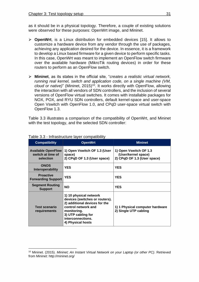
Chapter 3: Test topology setup 31
as it should be in a physical topology. Therefore, a couple of existing solutions were observed for these purposes: OpenWrt image, and Mininet. OpenWrt, is a Linux distribution for embedded devices [15]. It allows to
customize a hardware device from any vendor through the use of packages, achieving any application desired for the device. In essence, it is a framework to develop a Linux based firmware for a given device to perform specific tasks. In this case, OpenWrt was meant to implement an OpenFlow switch firmware over the available hardware (MikroTik routing devices) in order for these routers to perform as an OpenFlow switch.
Mininet, as its states in the official site, “creates a realistic virtual network,
running real kernel, switch and application code, on a single machine (VM, cloud or native)” (Mininet, 2015)10. It works directly with OpenFlow, allowing the interaction with all vendors of SDN controllers, and the inclusion of several versions of OpenFlow virtual switches. It comes with installable packages for NOX, POX, and RYU SDN controllers, default kernel-space and user-space Open Vswitch with OpenFlow 1.0, and CPqD user-space virtual switch with OpenFlow 1.3.
Table 3.3 illustrates a comparison of the compatibility of OpenWrt, and Mininet with the test topology, and the selected SDN controller: Table 3.3 - Infrastructure layer compatibility
Compatibility OpenWrt Mininet
Available OpenFlow switch at time of
selection
1) Open Vswitch OF 1.3 (User space) 2) CPqD OF 1.3 (User space)
1) Open Vswitch OF 1.3 (User/kernel space) 2) CPqD OF 1.3 (User space)
ONOS Interoperability
YES YES
Proactive Forwarding Support
YES YES
Segment Routing Support
NO YES
Test scenario requirements
1) 10 physical network devices (switches or routers). 2) additional devices for the control network and monitoring. 3) UTP cabling for interconnections. 4) Physical hosts
1) 1 Physical computer hardware 2) Single UTP cabling
10 Mininet. (2015). Mininet; An Instant Virtual Network on your Laptop (or other PC). Retrieved from Mininet: http://mininet.org/
32 Research on path establishment methods performance on SDN-based networks
Despite that OpenWrt would have given a more realistic infrastructure layer, by using physical hosts and devices, it doesn’t support the use of Segment Routing, which is one of the path establishment methods that was meant to be tested in the network topology. At time of selection, the supported versions of Open Vswitch within OpenWrt and Mininet did not support a feature called group-chaining [17], which is an optional feature of OpenFlow 1.3 that uses a group entry to points out a packet to a secondary group, and even to a third group or output port. This action is necessary to carry out the segment sequencing in the IP packet (Only CPqD had support for this feature). The CPqD version in OpenWrt did not support Segment Routing either, in which the reason is not clear since the Segment Routing driver supports the virtual switch through OpenFlow 1.3 [18]. However, it is suspected that the hardware implied in the Mikrotik router could limit the ability of the controller to use the full OpenFlow pipeline that enables the use of the necessary flow tables and group tables, but there was no documentation found on the Mikrotik routers to support this assumption. What was observed, was that during the interconnection of the Mikrotik routers with the SPRING-OPEN controller, the controller was unable to establish IP, MPLS, and ACL flow tables, and group tables as well. Having this considerable limitation with Segment Routing, it was decided to use Mininet to emulate the infrastructure layer under a single hardware. This setup will limit the topology in terms of bandwidth, since the supported virtual switch (CPqD switch) works on user-space level, and each switch in the topology will share hardware resources in the treatment of traffic. Nevertheless, in lower bandwidths the performance of the network is expected to be with high throughput and no packet loss in the traffic.
3.2.2 Hardware selection There is no clear indication about what the minimum hardware requirements should be for Mininet. However, a small topology based on 10 switches and a traffic generated by only 2 hosts, doesn’t require a demanding load processing for the hardware. Normally, if a virtual machine is used to host the Mininet application, its default settings of hardware resources are a single core processor, and a 1024MB of RAM memory according to the recommended downloadable virtual machine image for Mininet [19]. Based on this initial reference, a computer with similar hardware resources was available to host the Mininet application. The specifications of the selected computer are the following:
3.4GHz Intel® Pentium® D dual core processor 1GB RAM memory 64bit Ubuntu 14.04.01 1Gbps Ethernet NIC

Chapter 3: Test topology setup 33
3.3 Proactive Forwarding Setup Following the involved elements for the control and infrastructure layer, the topology to test the Proactive Forwarding method is illustrated on Fig 3.2:
S1
S2 S4S3 S5
S6
S7S9S10
h1 h2
ONOS Blackbird 1.1.0rc2
S8
Eth1
Eth1 Eth1
Eth1
Eth1
Eth1
Eth1
Eth1Eth1
Eth2
Eth2
Eth2
Eth2 Eth2 Eth2
Eth2
Eth2
Eth2
Eth3
Eth3Eth3
Eth3
Eth3
Eth1Eth2
PC 1 Interface em1
Eth3
10.0.0.1/24 10.0.0.2/24
10.60.1.1:6633
PC 2 Interface eth2
TCP interconnections
CPqD OF 1.3.4(User Space)
Figure 3.2 - Proactive Forwarding test topology
This topology is configured on Mininet to work under a single subnet, due to its L2 based routing. A Python script is used to construct the topology on Mininet (see TopoTestPF.py on Appendix B), in which the switches are set to point to the controller’s default TCP port 6633 to interact with it using OpenFlow messages, and to use the user space switch (CPqD). The switch interfaces bandwidth is dependent on the limitation of the test network, in which its bandwidth capacity is tested on the experimentation process in Chapter 5.
3.4 Segment Routing Setup The topology to test the Segment Routing method is presented on Fig. 3.3:
ONOS SPRING-OPEN
S1 S6
h1h2
10.0.0.5/24Mac: 00:00:00:00:00:01 10.1.1.5/24
Mac: 00:00:00:00:00:02
172.10.0.1/32SID: 101
10.60.1.1:6633
Gwy: 10.1.1.1/24Gwy: 10.0.0.1/24
Eth1
S2 S3 S5
S10 S9 S8 S7
172.10.0.2/32SID: 102
172.10.0.3/32SID: 103
172.10.0.4/32SID: 104
172.10.0.5/32SID: 105
172.10.0.6/32SID: 106
172.10.0.7/32SID: 107
172.10.0.8/32SID: 108
172.10.0.9/32SID: 109
172.10.0.10/32SID: 110
Eth1
Eth2 Eth1 Eth2
Eth3
Eth3
Eth1
Eth2 Eth1 Eth2
Eth3
Eth3
Eth2
Eth1
Eth1
Eth2
Eth1
S4
TCP interconnections
PC 1 Interface em1
PC 2 Interface Eth2
CPqD OF 1.3.4(User Space)
Figure 3.3 - Segment Routing test topology
34 Research on path establishment methods performance on SDN-based networks
In this case, the configuration of the topology is the same, but with small differences in the python script (see TopoTestSR.py on Appendix B), in which the host’s IP addresses are manually configured instead of being automatically assigned. This is in order to configure both hosts under different subnets for the ONOS Segment Routing prototype to work properly. Another big difference is that the controller plays a role in the construction of the network topology. It downloads a configuration to the CPqD switches in order to program the OpenFlow pipeline, enabling routing functions on each of them. In other words, it sets the switches to emulate SR nodes to perform Segment Routing operations, in which different subnets can be configured to the switch’s interfaces, and SID labels and loopback IP address can be assigned to each switch. The switches will depend on the controller’s network abstraction in order for them to emulate SR nodes. This is because the IP addressing and SID information is stored in the controller’s network abstraction. The routing information (IP and MPLS) is stored on the switches within specific flow tables initially programmed by the controller. The IP/MAC addressing and SID labeling are preconfigured on the controller through the use of a configuration file (see toptst-ctrl-SR.conf on appendix B), in which each switch is identified by the controller through their DPID assigned as a result of the python script.
3.5 Measurement tools For this research, accuracy in the measurement is not a mandatory objective. Nevertheless, it should be precise enough to reveal general behavior and tendencies of the path establishment methods towards the time response of the SDN controller. Therefore, the following tools were selected for the sampling and measurement of the SDN controller’s time response: iPerf, MGEN, and Wireshark.
3.5.1 iPerf iPerf is a tool for live measurements on IP networks, in which its main purpose is to determine the maximum achievable throughput in the IP network.11 It can be used for other measurements like jitter, and packet losses. It is customizable to generate UDP and TCP packets of different MTUs, and at a specified rate and interval of transmission. This tool acquires its statistics based on the number of packets transmitted within the transmission time and interval. It comprises two elements, a client and a server. The client generates the traffic to the server according to the packet specifications desired, and determines an average transmitted bandwidth; while
11 iPerf. iPerf – The network bandwidth measurement tool. Retrieved from iPerf: https://iperf.fr/
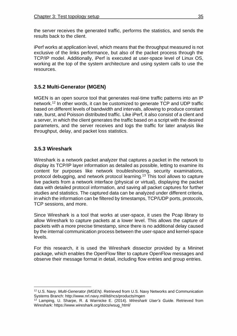
Chapter 3: Test topology setup 35
the server receives the generated traffic, performs the statistics, and sends the results back to the client. iPerf works at application level, which means that the throughput measured is not exclusive of the links performance, but also of the packet process through the TCP/IP model. Additionally, iPerf is executed at user-space level of Linux OS, working at the top of the system architecture and using system calls to use the resources.
3.5.2 Multi-Generator (MGEN) MGEN is an open source tool that generates real-time traffic patterns into an IP network.12 In other words, it can be customized to generate TCP and UDP traffic based on different levels of bandwidth and intervals, allowing to produce constant rate, burst, and Poisson distributed traffic. Like iPerf, it also consist of a client and a server, in which the client generates the traffic based on a script with the desired parameters, and the server receives and logs the traffic for later analysis like throughput, delay, and packet loss statistics.
3.5.3 Wireshark Wireshark is a network packet analyzer that captures a packet in the network to display its TCP/IP layer information as detailed as possible, letting to examine its content for purposes like network troubleshooting, security examinations, protocol debugging, and network protocol learning.13 This tool allows to capture live packets from a network interface (physical or virtual), displaying the packet data with detailed protocol information, and saving all packet captures for further studies and statistics. The captured data can be analyzed under different criteria, in which the information can be filtered by timestamps, TCP/UDP ports, protocols, TCP sessions, and more. Since Wireshark is a tool that works at user-space, it uses the Pcap library to allow Wireshark to capture packets at a lower level. This allows the capture of packets with a more precise timestamp, since there is no additional delay caused by the internal communication process between the user-space and kernel-space levels. For this research, it is used the Wireshark dissector provided by a Mininet package, which enables the OpenFlow filter to capture OpenFlow messages and observe their message format in detail, including flow entries and group entries.
12 U.S. Navy. Multi-Generator (MGEN). Retrieved from U.S. Navy Networks and Communication Systems Branch: http://www.nrl.navy.mil/itd/ncs/products/mgen 13 Lamping, U. Sharpe, R. & Warnicke E. (2014). Wireshark User’s Guide. Retrieved from Wireshark: https://www.wireshark.org/docs/wsug_html/
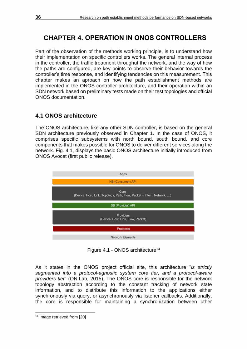
36 Research on path establishment methods performance on SDN-based networks
CHAPTER 4. OPERATION IN ONOS CONTROLLERS Part of the observation of the methods working principle, is to understand how their implementation on specific controllers works. The general internal process in the controller, the traffic treatment throughut the network, and the way of how the paths are configured, are key points to observe their behavior towards the controller’s time response, and identifying tendencies on this measurement. This chapter makes an aproach on how the path establishment methods are implemented in the ONOS controller architecture, and their operation within an SDN network based on preliminary tests made on their test topologies and official ONOS documentation.
4.1 ONOS architecture The ONOS architecture, like any other SDN controller, is based on the general SDN architecture previously observed in Chapter 1. In the case of ONOS, it comprises specific subsystems with north bound, south bound, and core components that makes possible for ONOS to deliver different services along the network. Fig. 4.1, displays the basic ONOS architecture initially introduced from ONOS Avocet (first public release).
Figure 4.1 - ONOS architecture14 As it states in the ONOS project official site, this architecture “is strictly segmented into a protocol-agnostic system core tier, and a protocol-aware providers tier” (ON.Lab, 2015). The ONOS core is responsible for the network topology abstraction according to the constant tracking of network state information, and to distribute this information to the applications either synchronously via query, or asynchronously via listener callbacks. Additionally, the core is responsible for maintaining a synchronization between other
14 Image retrieved from [20]
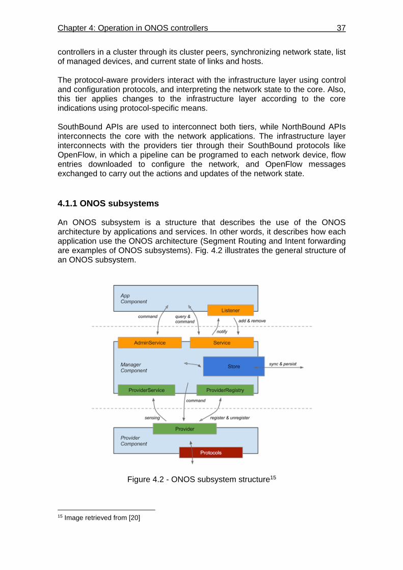
Chapter 4: Operation in ONOS controllers 37
controllers in a cluster through its cluster peers, synchronizing network state, list of managed devices, and current state of links and hosts. The protocol-aware providers interact with the infrastructure layer using control and configuration protocols, and interpreting the network state to the core. Also, this tier applies changes to the infrastructure layer according to the core indications using protocol-specific means. SouthBound APIs are used to interconnect both tiers, while NorthBound APIs interconnects the core with the network applications. The infrastructure layer interconnects with the providers tier through their SouthBound protocols like OpenFlow, in which a pipeline can be programed to each network device, flow entries downloaded to configure the network, and OpenFlow messages exchanged to carry out the actions and updates of the network state.
4.1.1 ONOS subsystems An ONOS subsystem is a structure that describes the use of the ONOS architecture by applications and services. In other words, it describes how each application use the ONOS architecture (Segment Routing and Intent forwarding are examples of ONOS subsystems). Fig. 4.2 illustrates the general structure of an ONOS subsystem.
Figure 4.2 - ONOS subsystem structure15
15 Image retrieved from [20]
38 Research on path establishment methods performance on SDN-based networks
This diagram shows the interaction between the architecture layers for each application. The provider component receives and configures the network state through the SouthBound protocols, then it exchanges network information with the manager component, in which devices can be registered to the core using the ProviderRegistry, the device and port information can be supplied using the ProviderService, and the core can give instructions to the provider component to be executed on the infrastructure layer. The manager component interacts with the application component through NorthBound APIs, in which the Listener and the Service are used to exchange Asynchronous notifications, and the AdminService to perform administrative actions like setting mastership to a device, removing decommissioned devices, among other thinks depending of the application. Within the core, the Store is responsible for synchronizing and indexing information with cluster peers.
4.2 Intent forwarding subsystem The Intent forwarding method is the ONOS version of Proactive Forwarding, in which the controller anticipates an end-to-end path to incoming traffic. In ONOS, this method works under one main subsystems (Intent subsystem), and uses others subsystems as support (i.e. Topology Subsystem).
4.2.1 Intent subsystem The Intent subsystem is a set of abstractions for conveying high-level intents for treatment of selected network traffic, allowing application to express their traffic needs, and conditioning the network accordingly. The intent name comes from the word intention as “state your intentions”, which is the analogy applied to applications, in which they state their intentions of conditioning the network through the use of policy-based directives. Intents can alter the network behavior based on network resources, constraints, specific criteria, and instructions [21]. The Intent application submits an Intent to the ONOS core, which accepts its specifications and translates them via Intent compilation, into actionable operations on the network environment. These actions are executed by an intent installation process that changes the network environment in terms of tunnel links being provisioned, flow entries being installed on a switch, or optical lambdas (wavelengths) being reserved [21]. A more detailed diagram of the Intent compilation process can be found on Appendix C. Figure 4.3 shows the interaction between the components of the Intent subsystem.
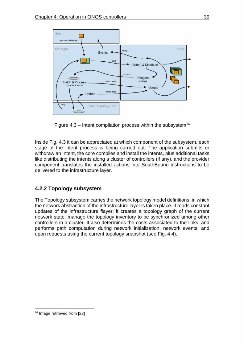
Chapter 4: Operation in ONOS controllers 39
Figure 4.3 – Intent compilation process within the subsystem16 Inside Fig. 4.3 it can be appreciated at which component of the subsystem, each stage of the intent process is being carried out. The application submits or withdraw an Intent, the core compiles and install the intents, plus additional tasks like distributing the intents along a cluster of controllers (if any), and the provider component translates the installed actions into SouthBound instructions to be delivered to the infrastructure layer.
4.2.2 Topology subsystem The Topology subsystem carries the network topology model definitions, in which the network abstraction of the infrastructure layer is taken place. It reads constant updates of the infrastructure flayer, it creates a topology graph of the current network state, manage the topology inventory to be synchronized among other controllers in a cluster. It also determines the costs associated to the links, and performs path computation during network initialization, network events, and upon requests using the current topology snapshot (see Fig. 4.4).
16 Image retrieved from [22]

40 Research on path establishment methods performance on SDN-based networks
Topology Listener
Path/Topology Service
Topology store
Topology provider
registry
Topology provider
service
Topology provider
Application component
Manager component
Provider componentProtocols
Figure 4.4 - Topology subsystem17 Intent forwarding relies on this subsystem to maintain the Intent subsystem updated on the current network topology through the Topology Listener, and to perform the end-to-end path computation through the Path Service. When a network event occurs and affect current paths, the Intent subsystem can react based on the information received on the Topology Listener, making decisions of either submit new Intents or withdraw the affected ones. Then, during the Intent compilation process, the Path Service is consulted for a best available path for the new end-to-end path.
4.2.2.1 Path service computation The Path Service uses a utility subsystem called, the Graph subsystem, to access the path algorithm used for the path computation. The algorithm used is the Dijkstra shortest-path algorithm, in which it calculates not only one, but also all shortest paths from source to destination. The default metric used is based on hop-count, but it can be customizable by using a self-designed lightweight function (the default state is used during the experimentation process). In the case of Intent Forwarding, this process is executed during Intent compilation, where the Intent subsystem consults the Path Service to determine the shortest path between 2 clients based on the current network state information. Then, the Intent is installed with the new path information, and translated into SouthBound instructions, setting the network devices to establish the end-to-end path according to the algorithm’s computation.
17 Image based upon Fig. 4.2 and [23]
Chapter 4: Operation in ONOS controllers 41
4.2.3 Intent forwarding operation There are several types of Intents in ONOS planned for Proactive Forwarding: Host-to-Host, Point-to-Point, Point-to-Multipoint, MPLS, and Optical connectivity Intents. Current ONOS controllers do not fully support all those Intents, but for the setup of the test topology, it is used the most common which are the Host-to-Host and Point-to-Point Intents. As the name states, these Intents establishes a path between 2 hosts or 2 interfaces, respectively, using the shortest path available. Basically, there are two ways of using Intent forwarding: dynamic and static configuration. They work under the application onos-app-ifwd, which can be installed before onos initialization or during onos operation, and represents the application component of the Intent subsystem. More information can be found on Appendix E for the installation procedure of ONOS blackbird and its Intent forwarding app.
4.2.3.1 Dynamic configuration The following steps, describes the process of dynamic path configuration on Intent forwarding:
1. The controller expects from the infrastructure layer either an OFPT_PACKET_IN message (for incoming traffic), or an OFPT_PORT_STATUS message (for switch or link failures).
2. The onos-app-fwd application submits a Host-to-Host intent to the manager component.
3. The manager component compiles the intent. Within this process the manager component consults the Path Service of the Topology subsystem to acquire the shortest path information.
4. The manager component installs the compiled intent into actionable instructions and send it to the provider component.
5. The provider component translates the instructions into flow entries.
6. The flow entries are downloaded to relevant switches using the OpenFlow proactive instantiation through OFPT_FLOW_MOD messages.
7. With the flow entries on the switches, the end-to-end path is established.
4.2.3.2 Static configuration There are 2 ways to statically configure paths using Intent Forwarding: Through a specific command, or through an application called push-test-intent used for testing operations [34], which is used during the experimentation process in this
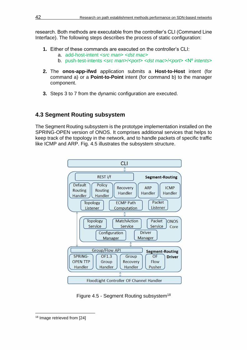
42 Research on path establishment methods performance on SDN-based networks
research. Both methods are executable from the controller’s CLI (Command Line Interface). The following steps describes the process of static configuration:
1. Either of these commands are executed on the controller’s CLI: a. add-host-intent <src man˃ <dst mac˃ b. push-test-intents <src man˃/<port˃ <dst mac˃/<port˃ <Nº intents˃
2. The onos-app-ifwd application submits a Host-to-Host intent (for command a) or a Point-to-Point intent (for command b) to the manager component.
3. Steps 3 to 7 from the dynamic configuration are executed.
4.3 Segment Routing subsystem The Segment Routing subsystem is the prototype implementation installed on the SPRING-OPEN version of ONOS. It comprises additional services that helps to keep track of the topology in the network, and to handle packets of specific traffic like ICMP and ARP. Fig. 4.5 illustrates the subsystem structure.
Figure 4.5 - Segment Routing subsystem18
18 Image retrieved from [24]

Chapter 4: Operation in ONOS controllers 43
Like in Proactive Forwarding, this subsystem comprises 3 components within the ONOS architecture. First, the Segment Routing application, which constructs a route based on default metrics or administration policies, handling packets of specific traffic. Second, the core component, which handles the network configuration and interprets the information received from the driver component. And third, the Segment-Routing Driver component, which programs the OpenFlow pipeline on the infrastructure layer, managing the group and flow entries to be pushed to the network devices. More detailed description can be found on Appendix D. This subsystem is designed to work using the MPLS data plane. The segment sequence is allocated on the MPLS stack, in which the MPLS labels are the SIDs identifying nodes and adjacencies. The packets are treated in each node according to the label found on the top of the stack until it reaches the Bottom of Stack (BoF), where the action of Penultimate Hop Popping (PHP) is executed on the node before the edge node connected to the destination network. The MPLS and IP routing tables are prepopulated on each switch during the controller initialization based on the current state of the network topology.
4.3.1 Path computation Within the Segment Routing application, there is a service called Segment Routing Manager (see Appendix D), which is the responsible for the path computation carried out in Segment Routing. It uses the ECMP-aware SPF algorithm based on Dijkstra to compute the shortest path along the nodes within the SDN network. Once all path computations are done, the Segment Routing Manager populates all routing rules to the IP and MPLS table of the switches. This means that all possible shortest ECMP paths are established from the controller’s initialization, and all incoming traffic to a specific destination will be guided through the multiple paths without consulting the controller first (as long the destination IP address is known on the IP routing table).
4.3.2 Group handling Before the IP and MPLS tables are populated, group entries are previously configured on the Segment-Routing Driver with the action buckets related with packet forwarding operations, PUSH and POP labeling, and ECMP load balancing. In this implementation of Segment Routing, Indirect and Select groups are used for these purposes. Let’s understand it further through the following scenarios reviewed on the test topology.

44 Research on path establishment methods performance on SDN-based networks
4.3.2.1 Packet forwarding When packets are processed either by an IP or MPLS table, most of the entries of these flow tables are associated with a group entry for forwarding actions. Within the associated group entry, there are action buckets that can execute actions like forwarding a packet to an output port, pushing and MPLS label and then sending a packet to an output port, or popping a label before sending out a packet. If only one label needs to be pushed, and there are no redundant links around, this actions are handled by Select groups, which also set the destination mac address of the next hop, and decrements MPLS TTL counters. An example of these actions can be seen on Appendix F.
4.3.2.2 Label stacking When multiple labels need to be pushed into an incoming packet, a combination of either Select or Indirect groups, or both, are used to execute a feature called group chaining. This implies that the action bucket of the first matched group entry with the packet, pushes an MPLS label and forwards the packet to another group entry, which can carry the same type of action bucket, and continue the process until the last matched group entry forwards the packet to an output port (see Appendix F for practical example). Along the path, each node that the packet traverses will carry out the actions matched with the label found on the top of stack, and extract the label using the POP action contained on the appropriate flow entry of the MPLS table, sending the packet to a group entry with only forwarding action to an output port for the next hop. This process is repeated along the way until the packet reaches to the bottom of stack.
4.3.2.3 ECMP groups When a neighbor node is reachable through more than one link or adjacency, the Segment-Routing Driver configures Select groups (or ECMP groups) to assign action buckets per link under one single group. Each action bucket, executes indirect group actions like MPLS labeling, output port forwarding, or next group forwarding. The particular case here, is that when traffic is forwarded to this group, it uses the action buckets within the group to forward the traffic along the multiple links assigned to the group (see Appendix F for practical example). By default, Segment Routing distribute the traffic in a Round-Robin behavior along the action buckets. Additionally, different links pointing to different neighbors can be included under the same ECMP group by configuring Adj-SIDs, identifying the set of links as one adjacency.
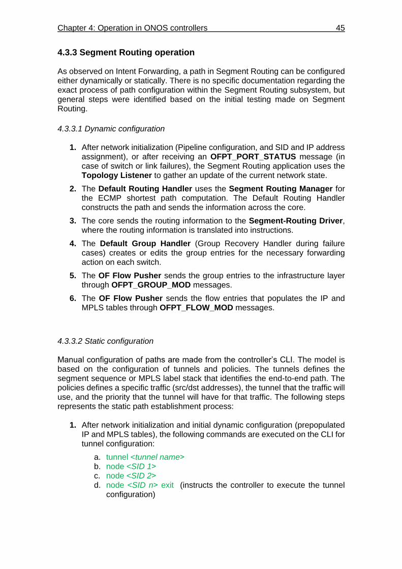
Chapter 4: Operation in ONOS controllers 45
4.3.3 Segment Routing operation As observed on Intent Forwarding, a path in Segment Routing can be configured either dynamically or statically. There is no specific documentation regarding the exact process of path configuration within the Segment Routing subsystem, but general steps were identified based on the initial testing made on Segment Routing.
4.3.3.1 Dynamic configuration
1. After network initialization (Pipeline configuration, and SID and IP address assignment), or after receiving an OFPT_PORT_STATUS message (in case of switch or link failures), the Segment Routing application uses the Topology Listener to gather an update of the current network state.
2. The Default Routing Handler uses the Segment Routing Manager for the ECMP shortest path computation. The Default Routing Handler constructs the path and sends the information across the core.
3. The core sends the routing information to the Segment-Routing Driver, where the routing information is translated into instructions.
4. The Default Group Handler (Group Recovery Handler during failure cases) creates or edits the group entries for the necessary forwarding action on each switch.
5. The OF Flow Pusher sends the group entries to the infrastructure layer through OFPT_GROUP_MOD messages.
6. The OF Flow Pusher sends the flow entries that populates the IP and MPLS tables through OFPT_FLOW_MOD messages.
4.3.3.2 Static configuration Manual configuration of paths are made from the controller’s CLI. The model is based on the configuration of tunnels and policies. The tunnels defines the segment sequence or MPLS label stack that identifies the end-to-end path. The policies defines a specific traffic (src/dst addresses), the tunnel that the traffic will use, and the priority that the tunnel will have for that traffic. The following steps represents the static path establishment process:
1. After network initialization and initial dynamic configuration (prepopulated IP and MPLS tables), the following commands are executed on the CLI for tunnel configuration:
a. tunnel <tunnel name˃ b. node <SID 1˃ c. node <SID 2˃ d. node <SID n˃ exit (instructs the controller to execute the tunnel
configuration)

46 Research on path establishment methods performance on SDN-based networks
2. The Policy Routing Handler identifies the switches tagged by the SIDs members of the tunnel, and identifies the adjacencies between them. Then, it sends forwarding instructions to the core to be passed on to the Segment-Routing Driver.
3. The Group Handler creates the necessary groups that will establish the segment sequence.
4. The OF Flow Pusher sends the group entries to the edge switches through OFPT_GROUP_MOD messages.
5. The following commands are executed on the CLI for the policy configuration:
a. policy <policy name˃ policy-type tunnel-flow b. flow-entry ip <src IP address/mask˃ <dst IP address/mask˃ c. tunnel <tunnel name˃ d. priority <priority number˃ e. exit (instructs the controller to execute the policy configuration)
6. The Policy Routing Handler identifies the tunnel assigned to the policy,
and prepares policy instructions based on the configured parameters to send it across the core to the Segment-Routing Driver.
7. The OF Flow Pusher sends the necessary flow entries to the edge switches using OFPT_FLOW_MOD messages to populate the ACL table with the policies.
The flow entries on the ACL table will override any default instruction contained within the IP and MPLS tables. This ultimately will force the desired traffic to follow the static path, rather than following the dynamically computed path. The tunnels and policies are unidirectional, this means that for establishing bidirectional paths, a pair of tunnels and policies must be configured.
4.4 OpenFlow pipeline utilization Both path establishment methods require the traffic to be processed by the OpenFlow pipeline in different sequence of tables. Generally, with Intent forwarding the traffic is processed only by flow tables, while in Segment Routing the traffic needs to be processed by flow tables and group tables.
4.4.1 Intent Forwarding pipeline Intent forwarding only use a flow table with match fields based on mac address information (see Fig. 4.6), being enough for Intent Forwarding to execute L2 based routing decisions. There is no detailed information about the exact number of flow tables that can be used in Intent Forwarding. However, since this application is intended in the long run, not only to establish a route based on shortest path decisions, but also based on policies like QoS, and traffic criteria, it suggests the use of an OpenFlow pipeline with more than one flow table. In the
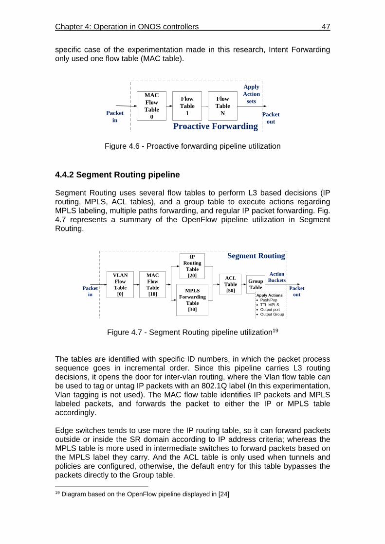
Chapter 4: Operation in ONOS controllers 47
specific case of the experimentation made in this research, Intent Forwarding only used one flow table (MAC table).
Flow
Table
N
Proactive Forwarding
Packet
in
Flow
Table
1
MAC
Flow
Table
0 Packet
out
Apply
Action
sets
Figure 4.6 - Proactive forwarding pipeline utilization
4.4.2 Segment Routing pipeline Segment Routing uses several flow tables to perform L3 based decisions (IP routing, MPLS, ACL tables), and a group table to execute actions regarding MPLS labeling, multiple paths forwarding, and regular IP packet forwarding. Fig. 4.7 represents a summary of the OpenFlow pipeline utilization in Segment Routing.
MPLS
Forwarding
Table
[30]
ACL
Table
[50]
Group
Table
Segment Routing
Packet
in
Packet
out
IP
Routing
Table
[20]MAC
Flow
Table
[10]
VLAN
Flow
Table
[0]
Action
Buckets
Apply Actions
Push/Pop
TTL MPLS
Output port
Output Group
Figure 4.7 - Segment Routing pipeline utilization19 The tables are identified with specific ID numbers, in which the packet process sequence goes in incremental order. Since this pipeline carries L3 routing decisions, it opens the door for inter-vlan routing, where the Vlan flow table can be used to tag or untag IP packets with an 802.1Q label (In this experimentation, Vlan tagging is not used). The MAC flow table identifies IP packets and MPLS labeled packets, and forwards the packet to either the IP or MPLS table accordingly. Edge switches tends to use more the IP routing table, so it can forward packets outside or inside the SR domain according to IP address criteria; whereas the MPLS table is more used in intermediate switches to forward packets based on the MPLS label they carry. And the ACL table is only used when tunnels and policies are configured, otherwise, the default entry for this table bypasses the packets directly to the Group table.
19 Diagram based on the OpenFlow pipeline displayed in [24]
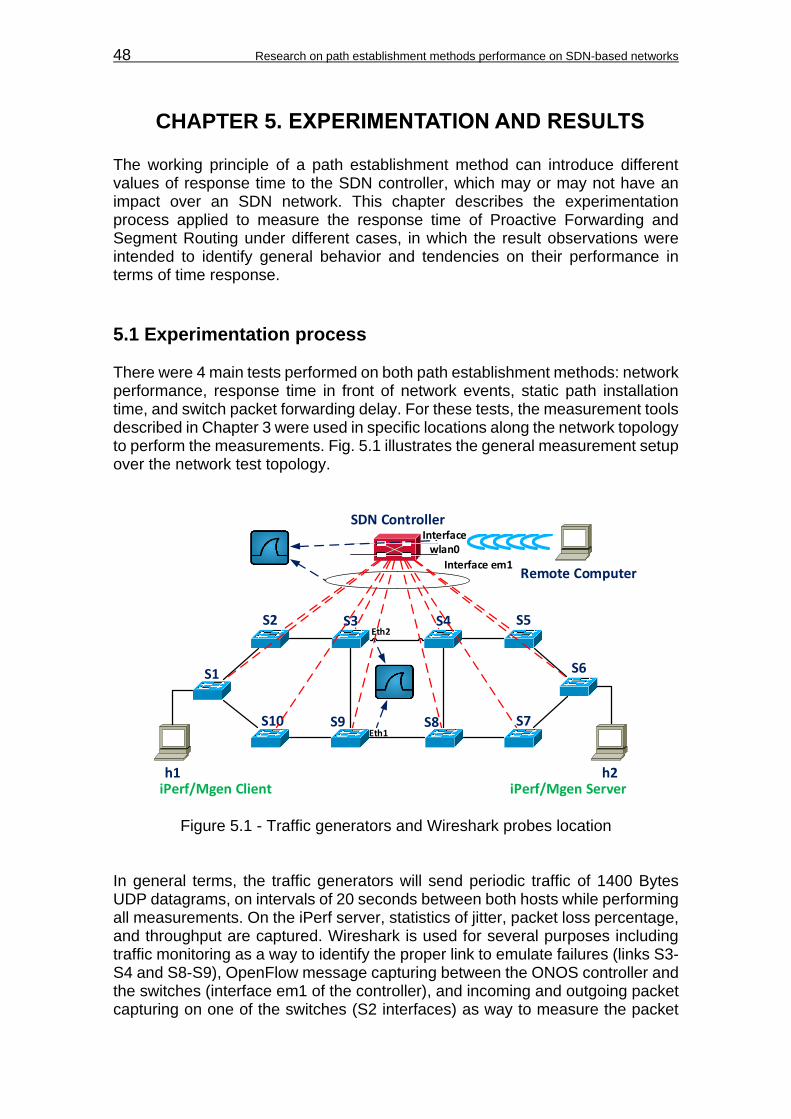
48 Research on path establishment methods performance on SDN-based networks
CHAPTER 5. EXPERIMENTATION AND RESULTS The working principle of a path establishment method can introduce different values of response time to the SDN controller, which may or may not have an impact over an SDN network. This chapter describes the experimentation process applied to measure the response time of Proactive Forwarding and Segment Routing under different cases, in which the result observations were intended to identify general behavior and tendencies on their performance in terms of time response.
5.1 Experimentation process There were 4 main tests performed on both path establishment methods: network performance, response time in front of network events, static path installation time, and switch packet forwarding delay. For these tests, the measurement tools described in Chapter 3 were used in specific locations along the network topology to perform the measurements. Fig. 5.1 illustrates the general measurement setup over the network test topology.
S1
S2 S4S3 S5
S6
S7S9S10
h1 h2
SDN Controller
S8Eth1
Eth2
Interface em1Remote Computer
Interface wlan0
iPerf/Mgen Client iPerf/Mgen Server
Figure 5.1 - Traffic generators and Wireshark probes location In general terms, the traffic generators will send periodic traffic of 1400 Bytes UDP datagrams, on intervals of 20 seconds between both hosts while performing all measurements. On the iPerf server, statistics of jitter, packet loss percentage, and throughput are captured. Wireshark is used for several purposes including traffic monitoring as a way to identify the proper link to emulate failures (links S3-S4 and S8-S9), OpenFlow message capturing between the ONOS controller and the switches (interface em1 of the controller), and incoming and outgoing packet capturing on one of the switches (S2 interfaces) as way to measure the packet

Chapter 5: Experimentation and results 49
forwarding delay. Wireshark will also capture packets coming from a remote computer, in which the CLI commands for static route configuration are executed. For each measurement a number of 100 samples are taken to acquire proper results of average values, sample standard deviation, and media intervals at 95% of confidence. For confidence intervals the samples are plotted in a Normal Quantile-Quantile Plot to verify that the behavior of the samples follows a normal distribution, and ensure that the measurement is not affected. More information on the description of this procedure can be found on Appendix G.
5.1.1 Network performance measurement The network performance is measured under steady state conditions, meaning that the network topology does not experience any network event that can change the network state during the test. Moreover, the test is performed after the network is stabilized on its initial traffic forwarding, in which the paths are already pre-established. The goal is to observe how the network topology behaves in terms of traffic forwarding without the influence of external factors allowing to identify the limits of the topology, and to ensure proper testing using stable values of bitrates. Traffic is measured in five main bandwidths: 100 Kbps, 1Mbps, 10Mbps, 100 Mbps, and 1 Gbps. The results to observe are the receiving bitrate and packet loss percentage. Using the more stable bandwidth (0% packet loss and end to end sustained bitrate), the round trip time and jitter are also measured.
5.1.2 Response time measurement in front of network events The response time is measured under network event conditions, such as link failures during packet transmission. The link failures are emulated by shutting down specific links of the network (S3-S4 and S8-S9) in the Mininet console, while the traffic is being forwarded through those links (all possible paths in the topology will use either one or both links). The Wireshark tool is used to measure the time that takes the controller to reroute the paths and redirect the traffic. OpenFlow messages between the SDN controller and the switches are captured based on [14]. The time frame is measured between the instant where the network event is detected by the SDN controller (OFPT_PORT_STATUS message), and the last flow message (OFPT_FLOW_MOD) sent by the SDN controller (see Fig. 5.2). This is the time period in which the controller starts and finalize the process of path redirection, and hence, the response time in front of network events. The processing time of the switches to detect the failure, and send the port status messages are not taken into account. Thus, the measurement only focuses on the performance of the SDN controller to react in front of network events.
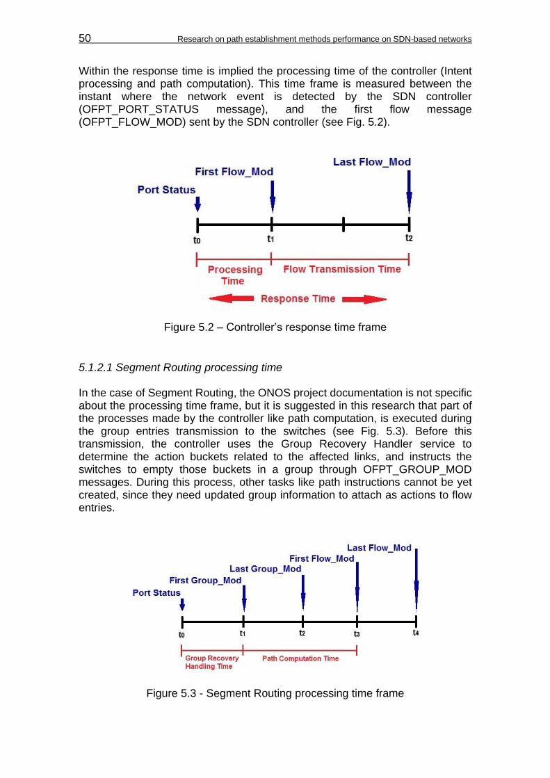
50 Research on path establishment methods performance on SDN-based networks
Within the response time is implied the processing time of the controller (Intent processing and path computation). This time frame is measured between the instant where the network event is detected by the SDN controller (OFPT_PORT_STATUS message), and the first flow message (OFPT_FLOW_MOD) sent by the SDN controller (see Fig. 5.2).
Figure 5.2 – Controller’s response time frame
5.1.2.1 Segment Routing processing time In the case of Segment Routing, the ONOS project documentation is not specific about the processing time frame, but it is suggested in this research that part of the processes made by the controller like path computation, is executed during the group entries transmission to the switches (see Fig. 5.3). Before this transmission, the controller uses the Group Recovery Handler service to determine the action buckets related to the affected links, and instructs the switches to empty those buckets in a group through OFPT_GROUP_MOD messages. During this process, other tasks like path instructions cannot be yet created, since they need updated group information to attach as actions to flow entries.
Figure 5.3 - Segment Routing processing time frame
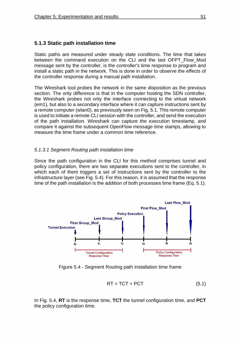
Chapter 5: Experimentation and results 51
5.1.3 Static path installation time Static paths are measured under steady state conditions. The time that takes between the command execution on the CLI and the last OFPT_Flow_Mod message sent by the controller, is the controller's time response to program and install a static path in the network. This is done in order to observe the effects of the controller response during a manual path installation. The Wireshark tool probes the network in the same disposition as the previous section. The only difference is that in the computer hosting the SDN controller, the Wireshark probes not only the interface connecting to the virtual network (em1), but also to a secondary interface where it can capture instructions sent by a remote computer (wlan0), as previously seen on Fig. 5.1. This remote computer is used to initiate a remote CLI session with the controller, and send the execution of the path installation. Wireshark can capture the execution timestamp, and compare it against the subsequent OpenFlow message time stamps, allowing to measure the time frame under a common time reference.
5.1.3.1 Segment Routing path installation time Since the path configuration in the CLI for this method comprises tunnel and policy configuration, there are two separate executions sent to the controller, in which each of them triggers a set of instructions sent by the controller to the infrastructure layer (see Fig. 5.4). For this reason, it is assumed that the response time of the path installation is the addition of both processes time frame (Eq. 5.1).
Figure 5.4 - Segment Routing path installation time frame
RT = TCT + PCT (5.1) In Fig. 5.4, RT is the response time, TCT the tunnel configuration time, and PCT the policy configuration time.
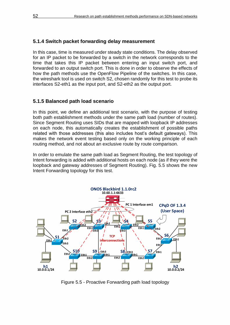
52 Research on path establishment methods performance on SDN-based networks
5.1.4 Switch packet forwarding delay measurement In this case, time is measured under steady state conditions. The delay observed for an IP packet to be forwarded by a switch in the network corresponds to the time that takes this IP packet between entering an input switch port, and forwarded to an output switch port. This is done in order to observe the effects of how the path methods use the OpenFlow Pipeline of the switches. In this case, the wireshark tool is used on switch S2, chosen randomly for this test to probe its interfaces S2-eth1 as the input port, and S2-eth2 as the output port.
5.1.5 Balanced path load scenario In this point, we define an additional test scenario, with the purpose of testing both path establishment methods under the same path load (number of routes). Since Segment Routing uses SIDs that are mapped with loopback IP addresses on each node, this automatically creates the establishment of possible paths related with those addresses (this also includes host’s default gateways). This makes the network event testing based only on the working principle of each routing method, and not about an exclusive route by route comparison. In order to emulate the same path load as Segment Routing, the test topology of Intent forwarding is added with additional hosts on each node (as if they were the loopback and gateway addresses of Segment Routing). Fig. 5.5 shows the new Intent Forwarding topology for this test.
S1
S2 S4S3 S5
S6
S7S9S10
h1 h2
ONOS Blackbird 1.1.0rc2
S8
Eth1
Eth1 Eth1
Eth1
Eth1
Eth1
Eth1
Eth1Eth1
Eth2
Eth2
Eth2
Eth2 Eth2 Eth2
Eth2
Eth2
Eth2
Eth3
Eth3Eth3
Eth3
Eth3
Eth1Eth2
PC 1 Interface em1
Eth3
10.0.0.1/24 10.0.0.2/24
10.60.1.1:6633
PC 2 Interface eth2
TCP interconnections
CPqD OF 1.3.4(User Space)
Figure 5.5 - Proactive Forwarding path load topology
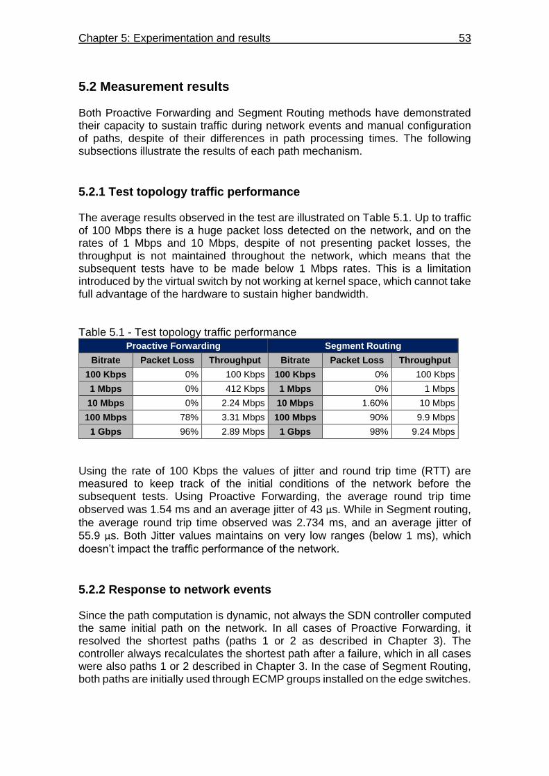
Chapter 5: Experimentation and results 53
5.2 Measurement results Both Proactive Forwarding and Segment Routing methods have demonstrated their capacity to sustain traffic during network events and manual configuration of paths, despite of their differences in path processing times. The following subsections illustrate the results of each path mechanism.
5.2.1 Test topology traffic performance The average results observed in the test are illustrated on Table 5.1. Up to traffic of 100 Mbps there is a huge packet loss detected on the network, and on the rates of 1 Mbps and 10 Mbps, despite of not presenting packet losses, the throughput is not maintained throughout the network, which means that the subsequent tests have to be made below 1 Mbps rates. This is a limitation introduced by the virtual switch by not working at kernel space, which cannot take full advantage of the hardware to sustain higher bandwidth. Table 5.1 - Test topology traffic performance
Proactive Forwarding Segment Routing
Bitrate Packet Loss Throughput Bitrate Packet Loss Throughput
100 Kbps 0% 100 Kbps 100 Kbps 0% 100 Kbps
1 Mbps 0% 412 Kbps 1 Mbps 0% 1 Mbps
10 Mbps 0% 2.24 Mbps 10 Mbps 1.60% 10 Mbps
100 Mbps 78% 3.31 Mbps 100 Mbps 90% 9.9 Mbps
1 Gbps 96% 2.89 Mbps 1 Gbps 98% 9.24 Mbps
Using the rate of 100 Kbps the values of jitter and round trip time (RTT) are measured to keep track of the initial conditions of the network before the subsequent tests. Using Proactive Forwarding, the average round trip time
observed was 1.54 ms and an average jitter of 43 µs. While in Segment routing,
the average round trip time observed was 2.734 ms, and an average jitter of
55.9 µs. Both Jitter values maintains on very low ranges (below 1 ms), which
doesn’t impact the traffic performance of the network.
5.2.2 Response to network events Since the path computation is dynamic, not always the SDN controller computed the same initial path on the network. In all cases of Proactive Forwarding, it resolved the shortest paths (paths 1 or 2 as described in Chapter 3). The controller always recalculates the shortest path after a failure, which in all cases were also paths 1 or 2 described in Chapter 3. In the case of Segment Routing, both paths are initially used through ECMP groups installed on the edge switches.

54 Research on path establishment methods performance on SDN-based networks
After a failure, the controller stays with either one of the paths (depending on the link failure location). Table 5.2 displays the minimum, maximum, and average time of response that the controller took to process the path redirection, and to completely install it into
the network. It also shows the sample standard deviation (σ) and the 95%
Confidence Interval (CI). Table 5.2 - Network event performance
Proactive Forwarding Segment Routing
Description Processing Time Response Time Description Processing Time Response Time
Minimum 22.513 ms 28.554 ms Minimum 112.232 ms 197.89 ms
Maximum 55.978 ms 64.292 ms Maximum 264.361 ms 435.843 ms
Average 25.226 ms 40.753 ms Average 122.399 ms 265.326 ms
Sample σ 4.89 ms 6.178 ms Sample σ 20.814 ms 56.432 ms
95% CI 24.25 ms - 26.2 ms 39.52 ms - 41.97 ms 95% CI 118.27 ms - 126.53 ms 254.13 ms - 276.52 ms
5.2.2.1 Jitter measurement In all the measurements, there was a minimum traffic interruption observed in both methods. In Proactive Forwarding, there was 0.0012% of average packet loss between hosts h1 and h2, with a 95% confidence that the mean jitter
maintains on the range between 59.2 µs and 70.9 µs. While in Segment Routing,
the average packet loss was 0.0034%, with a 95% confidence that the mean jitter
is maintained within the range between 52.6 µs and 61.3 µs.
5.2.3 Response to static path installation For the static path installation measurement, a point to point intent is manually configured on the controller using the ONOS built-in app push-test-intent. 100 intents were emulated to measure 100 path installations, where the app execution was made from a remote computer, and its timestamp captured by Wireshark as earlier described in Figure 5.1. Table 5.3 illustrates the minimum, maximum, and average path installation response time, as well as the sample standard deviation
(σ) and the 95% Confidence Interval (CI).
Table 5.3 - Static path installation response
Proactive Forwarding Segment Routing
Description Path installation time Description Path installation time
Minimum 27.125 ms Minimum 5.371 ms
Maximum 77.752 ms Maximum 16.729 ms
Average 52.29 ms Average 11.452 ms
Sample σ 13.679 ms Sample σ 2.488 ms
95% CI 49.57 ms - 55 ms 95% CI 10.959 ms - 11.946 ms

Chapter 5: Experimentation and results 55
Let’s remember that in Segment Routing, the path installation time is considered as the sum of tunnel configuration, and policy configuration times described on Eq. 5.1, which were measured to construct the path installation time. For detailed sample information tables, consult Appendix H.
5.2.4 Switch packet forwarding delay For Proactive Forwarding, packet switching through the measured switch (S2)
had an average delay of 186.49 µs, in which the mean delay is within the range
of 178.358 µs and 194.621µs, with a confidence level of 95%. While in Segment
Routing, the average packet forwarding delay observed on the switch was
290.2 µs with 95% confidence that the mean delay is within the range between
282.796 µs and 297.603 µs. A complete table of the samples measured can be
found on Appendix H.
5.2.5 Response to network events with balanced path load Maintaining the Intent Forwarding topology with 14 hosts, proved difficult to the ONOS controller. Normally, according to the number of hosts, switches, and links, the controller submits a specific number of intents, installing specific number of flow entries. In this case, at every time that the controller recovered the failed link to start the test all over again, it installed more flow entries than before, increasing the main flow registry stored in the controller. Fig. 5.6 displays the CLI output of the number of flows and intents for every time the test is executed.
Figure 5.6 - Counters summary CLI output
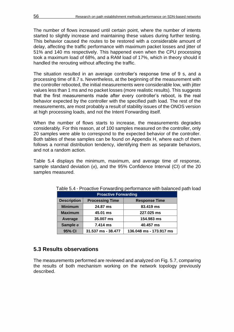
56 Research on path establishment methods performance on SDN-based networks
The number of flows increased until certain point, where the number of intents started to slightly increase and maintaining these values during further testing. This behavior caused the routes to be restored with a considerable amount of delay, affecting the traffic performance with maximum packet losses and jitter of 51% and 140 ms respectively. This happened even when the CPU processing took a maximum load of 68%, and a RAM load of 17%, which in theory should it handled the rerouting without affecting the traffic. The situation resulted in an average controller’s response time of 9 s, and a processing time of 8.7 s. Nevertheless, at the beginning of the measurement with the controller rebooted, the initial measurements were considerable low, with jitter values less than 1 ms and no packet losses (more realistic results). This suggests that the first measurements made after every controller’s reboot, is the real behavior expected by the controller with the specified path load. The rest of the measurements, are most probably a result of stability issues of the ONOS version at high processing loads, and not the Intent Forwarding itself. When the number of flows starts to increase, the measurements degrades considerably. For this reason, at of 100 samples measured on the controller, only 20 samples were able to correspond to the expected behavior of the controller. Both tables of these samples can be found on Appendix H, where each of them follows a normal distribution tendency, identifying them as separate behaviors, and not a random action. Table 5.4 displays the minimum, maximum, and average time of response,
sample standard deviation (σ), and the 95% Confidence Interval (CI) of the 20
samples measured.
Table 5.4 - Proactive Forwarding performance with balanced path load
Proactive Forwarding
Description Processing Time Response Time
Minimum 24.87 ms 83.419 ms
Maximum 45.01 ms 227.025 ms
Average 35.007 ms 154.983 ms
Sample σ 7.414 ms 40.457 ms
95% CI 31.537 ms - 38.477 136.048 ms - 173.917 ms
5.3 Results observations The measurements performed are reviewed and analyzed on Fig. 5.7, comparing the results of both mechanism working on the network topology previously described.
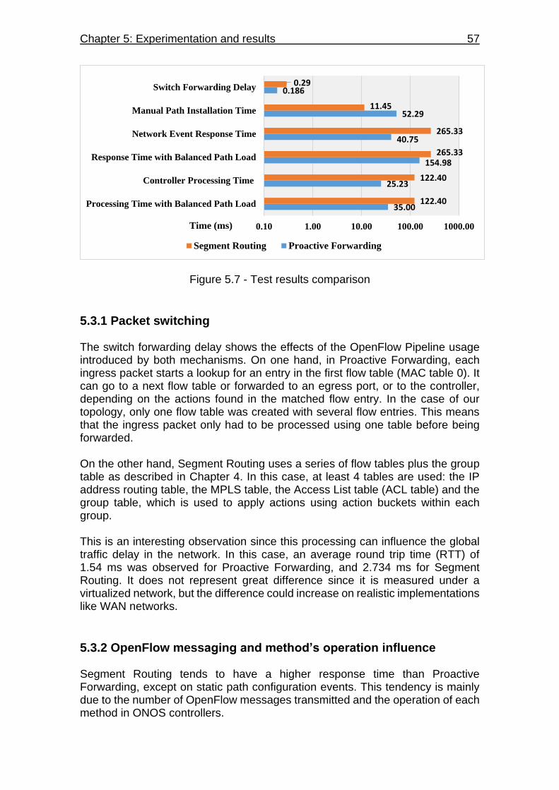
Chapter 5: Experimentation and results 57
Figure 5.7 - Test results comparison
5.3.1 Packet switching The switch forwarding delay shows the effects of the OpenFlow Pipeline usage introduced by both mechanisms. On one hand, in Proactive Forwarding, each ingress packet starts a lookup for an entry in the first flow table (MAC table 0). It can go to a next flow table or forwarded to an egress port, or to the controller, depending on the actions found in the matched flow entry. In the case of our topology, only one flow table was created with several flow entries. This means that the ingress packet only had to be processed using one table before being forwarded. On the other hand, Segment Routing uses a series of flow tables plus the group table as described in Chapter 4. In this case, at least 4 tables are used: the IP address routing table, the MPLS table, the Access List table (ACL table) and the group table, which is used to apply actions using action buckets within each group. This is an interesting observation since this processing can influence the global traffic delay in the network. In this case, an average round trip time (RTT) of 1.54 ms was observed for Proactive Forwarding, and 2.734 ms for Segment Routing. It does not represent great difference since it is measured under a virtualized network, but the difference could increase on realistic implementations like WAN networks.
5.3.2 OpenFlow messaging and method’s operation influence Segment Routing tends to have a higher response time than Proactive Forwarding, except on static path configuration events. This tendency is mainly due to the number of OpenFlow messages transmitted and the operation of each method in ONOS controllers.
35.00
25.23
154.98
40.75
52.29
0.186
122.40
122.40
265.33
265.33
11.45
0.29
0.10 1.00 10.00 100.00 1000.00
Processing Time with Balanced Path Load
Controller Processing Time
Response Time with Balanced Path Load
Network Event Response Time
Manual Path Installation Time
Switch Forwarding Delay
Segment Routing Proactive Forwarding
Time (ms)
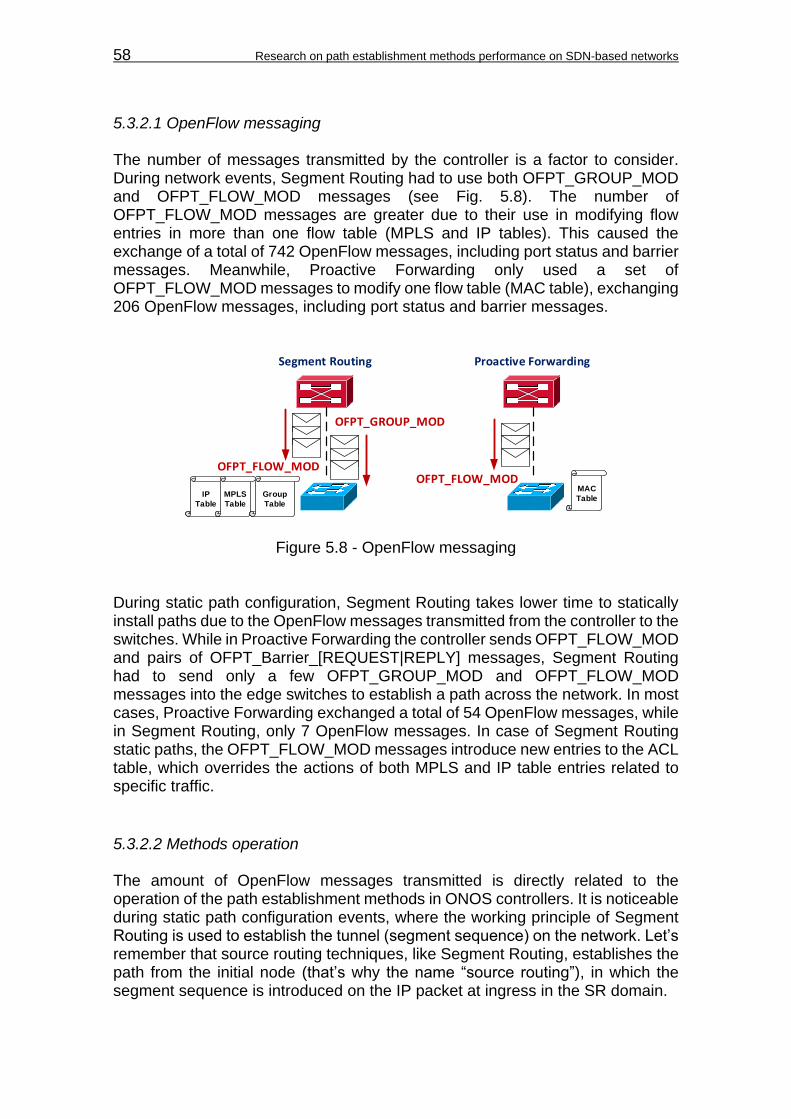
58 Research on path establishment methods performance on SDN-based networks
5.3.2.1 OpenFlow messaging The number of messages transmitted by the controller is a factor to consider. During network events, Segment Routing had to use both OFPT_GROUP_MOD and OFPT_FLOW_MOD messages (see Fig. 5.8). The number of OFPT_FLOW_MOD messages are greater due to their use in modifying flow entries in more than one flow table (MPLS and IP tables). This caused the exchange of a total of 742 OpenFlow messages, including port status and barrier messages. Meanwhile, Proactive Forwarding only used a set of OFPT_FLOW_MOD messages to modify one flow table (MAC table), exchanging 206 OpenFlow messages, including port status and barrier messages.
OFPT_GROUP_MOD
OFPT_FLOW_MOD
Segment Routing
OFPT_FLOW_MOD
Proactive Forwarding
IP
Table
MPLS
Table
Group
Table
MAC
Table
Figure 5.8 - OpenFlow messaging During static path configuration, Segment Routing takes lower time to statically install paths due to the OpenFlow messages transmitted from the controller to the switches. While in Proactive Forwarding the controller sends OFPT_FLOW_MOD and pairs of OFPT_Barrier_[REQUEST|REPLY] messages, Segment Routing had to send only a few OFPT_GROUP_MOD and OFPT_FLOW_MOD messages into the edge switches to establish a path across the network. In most cases, Proactive Forwarding exchanged a total of 54 OpenFlow messages, while in Segment Routing, only 7 OpenFlow messages. In case of Segment Routing static paths, the OFPT_FLOW_MOD messages introduce new entries to the ACL table, which overrides the actions of both MPLS and IP table entries related to specific traffic.
5.3.2.2 Methods operation The amount of OpenFlow messages transmitted is directly related to the operation of the path establishment methods in ONOS controllers. It is noticeable during static path configuration events, where the working principle of Segment Routing is used to establish the tunnel (segment sequence) on the network. Let’s remember that source routing techniques, like Segment Routing, establishes the path from the initial node (that’s why the name “source routing”), in which the segment sequence is introduced on the IP packet at ingress in the SR domain.
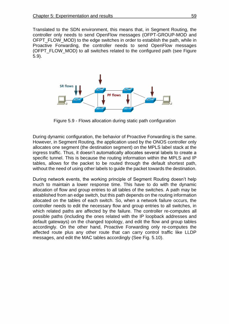
Chapter 5: Experimentation and results 59
Translated to the SDN environment, this means that, in Segment Routing, the controller only needs to send OpenFlow messages (OFPT-GROUP-MOD and OFPT_FLOW_MOD) to the edge switches in order to establish the path, while in Proactive Forwarding, the controller needs to send OpenFlow messages (OFPT_FLOW_MOD) to all switches related to the configured path (see Figure 5.9).
SR flows
PF flows
Figure 5.9 - Flows allocation during static path configuration During dynamic configuration, the behavior of Proactive Forwarding is the same. However, in Segment Routing, the application used by the ONOS controller only allocates one segment (the destination segment) on the MPLS label stack at the ingress traffic. Thus, it doesn’t automatically allocates several labels to create a specific tunnel. This is because the routing information within the MPLS and IP tables, allows for the packet to be routed through the default shortest path, without the need of using other labels to guide the packet towards the destination. During network events, the working principle of Segment Routing doesn’t help much to maintain a lower response time. This have to do with the dynamic allocation of flow and group entries to all tables of the switches. A path may be established from an edge switch, but this path depends on the routing information allocated on the tables of each switch. So, when a network failure occurs, the controller needs to edit the necessary flow and group entries to all switches, in which related paths are affected by the failure. The controller re-computes all possible paths (including the ones related with the IP loopback addresses and default gateways) on the changed topology, and edit the flow and group tables accordingly. On the other hand, Proactive Forwarding only re-computes the affected route plus any other route that can carry control traffic like LLDP messages, and edit the MAC tables accordingly (See Fig. 5.10).
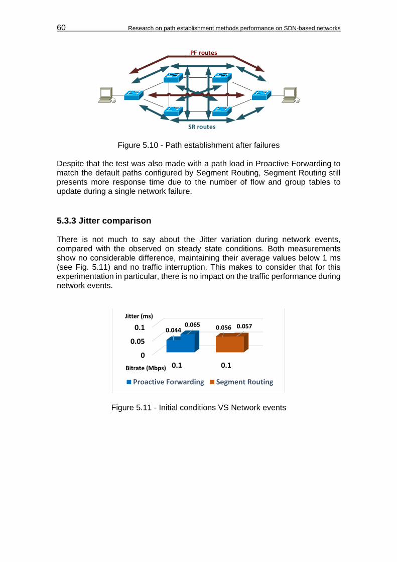
60 Research on path establishment methods performance on SDN-based networks
SR routes
PF routes
Figure 5.10 - Path establishment after failures Despite that the test was also made with a path load in Proactive Forwarding to match the default paths configured by Segment Routing, Segment Routing still presents more response time due to the number of flow and group tables to update during a single network failure.
5.3.3 Jitter comparison There is not much to say about the Jitter variation during network events, compared with the observed on steady state conditions. Both measurements show no considerable difference, maintaining their average values below 1 ms (see Fig. 5.11) and no traffic interruption. This makes to consider that for this experimentation in particular, there is no impact on the traffic performance during network events.
Figure 5.11 - Initial conditions VS Network events
0
0.05
0.1
0.1 0.1
0.044 0.0560.065 0.057
Proactive Forwarding Segment Routing
Bitrate (Mbps)
Jitter (ms)

Conclusions 61
CONCLUSIONS Path establishment methods can induce response time to an SDN controller based on their working principle and their interaction with the OpenFlow protocol. In the case of the studied methods (Proactive Forwarding and Segment Routing), the induced response time is more significant during network failures, due to the increased modification of OpenFlow tables in most of the switches to reestablish the paths. From this point, there are several observations: 1. Despite that Segment Routing establishes the paths from the edge nodes, it
cannot take full advantage of this behavior during network failures, since the paths depends on the routing information stored dynamically on the IP and MPLS tables.
2. In both methods, the controller sends several set of repeated
OFPT_FLOW_MOD and OFPT_GROUP_MOD messages to a switch, carrying the same instructions. This increases the number of messages that the controller sends to the switches, and hence the response time towards a single operation.
3. The overall traffic performance can be maintained in Segment Routing as long
as the topology permits to establish multiple independent paths to execute FRR in case of failures. However, behind the scenes the controller’s response time increase, due to the re-computation of all possible paths affected by the failure.
4. This tendency between Segment Routing and Proactive Forwarding is
expected to be the same. Segment Routing continues to induce the controller to modify more OpenFlow tables than Proactive Forwarding, even when both are carrying the same path load. Let’s remember that Segment Routing is designed for L3 routing, which will always need to handle L3 routing information.
During static path configuration, is where Segment Routing takes full advantage of its working principle. In this situation, there is only need for the controller to send OpenFlow messages to the edge nodes to establish the path. This case is interesting, because business applications from the Application layer can use Segment Routing to establish a policy based tunnel without introducing significant processing demand to the controller. This particular advantage is the main reason of other investigations made on the subject, which suggests Source Routing (not specifically Segment Routing) as a possible alternative for SDN packet forwarding [7]. In another matter, it has been seen how the usage of the OpenFlow pipeline can introduce additional delay on the switch packet forwarding. Segment Routing, in this case, presented a higher packet forwarding delay, related to the number of OpenFlow tables processing every ingress IP packet. Although in the virtual network did not had impact over the traffic performance, it is an interesting observation to take into account for realistic networks, where the SR nodes are

62 Research on path establishment methods performance on SDN-based networks
geographically separated, and the global traffic delay comes to play an important role. For path establishment methods, every additional response time introduced to the controller for a single operation like path redirection, is a factor to take into account in cases like scalability and costs (OPEX and CAPEX). If the processing demand of the controller is rapidly increased by these operations (plus other operations regularly executed by the controller), there would be the need to extend and maintain more hardware resources on the controller, depending on the extent of the infrastructure layer (number of network devices and hosts). Maintaining a lower response time on the SDN controller, must be part of the effort to achieve performance efficiency. Performance that can guarantee an efficient use of the resources in terms of hardware and energy. Moreover, the adaptation of path establishment methods into SDN, allows for the use of lightweight network devices that reduces energy consumption, since each of them doesn’t execute routing protocols, or maintain a constant routing updates like normally happens with distributed systems.
From the point of view of the test topology The observed results are dependent of the hardware used. This means that with different hardware, the values of response time can change considerably for both path establishment methods. Nevertheless, based on their working principle and their operation in SDN, it can be expected the same tendency of these results, as long as the same implementation of these paths mechanisms are used. Let’s remember that the Segment Routing implementation used for this experimentation, is a prototype designed to work with the MPLS data plane. According to the IETF, there can be other types of implementations of Segment Routing like having extensions for OSPF, ISIS, and BGP, or as an instantiation of IPv6, in which the SIDs are represented by IPv6 addresses [12]. A test scenario using either of these types in SDN, could change the tendency of the results.
Future work This research offers several areas for further investigation and development. Key questions surfaced as a consequence of the experimentation: 1. Can the forwarding actions of Segment Routing be carried out by flow tables? According to OpenFlow specifications [3], and as described early in Chapter 1, Actions like MPLS Push/Pop and TTL decrement can be carried out by the Action Set at the end of the pipeline processing, which can be executed on a flow table. This may suggest a way of not using the group tables, reducing the pipeline processing, and the OpenFlow messages towards the infrastructure layer.

Conclusions 63
2. Can the repeated set of OpenFlow messages be reduced on both path
establishment methods? There is no specific ONOS documentation explaining why it sends this repeated set of instructions to the infrastructure layer, but further investigation can be carried out in order to analyze the possibility of reducing these set of messages, without compromising the operation of the path establishment methods. 3. Can the Segment Routing application be enhanced to support controller’s
cluster implementations? Being an ONOS subsystem, it gives the possibility to add a store service for synchronization among servers in a cluster, or among other instances of the controller. Further investigation would be needed about what information to synchronize, and how extensive would be the software development, in order for the cluster to perform the Segment Routing application as one entity towards the infrastructure layer. 4. How would be the scalability rate of the controller based on increasing traffic
and number of switches? This investigation can depart from the study of workloads on the SDN controllers, by using benchmark tools like Cbench. Although, it would need to be developed further to support current versions of OpenFlow. For Intent Forwarding, ONOS offers a series of tests involving the application push-test-intent over a controller cluster to observe the performance [34]. This study could lead to an estimation of how would be the scalability of the SDN controller using both path establishment methods.

64 Research on path establishment methods performance on SDN-based networks
REFERENCES [1]. DeCusatis, C. (2012). ODIN Volume 3: Software Defined Networking and
Open Flow. Retrieved from IBM: http://www-01.ibm.com/common/ssi/cgi-bin/ssialias?subtype=WH&infotype=SA&appname=STGE_QC_QC_USEN&htmlfid=QCW03021USEN&attachment=QCW03021USEN.PDF
[2]. Nadeau, T. D., & Gray, K. (2013). SDN: Software Defined Networks. In T. D. Nadeau, & K. Gray, SDN: Software Defined Networks (pp. 47-69). Sebastopol: O'Reilly Media Inc.
[3]. OpenFlow Switch Specification Version 1.3.4. (2014). Retrieved from Open Networking Foundation:
https://www.opennetworking.org/images/stories/downloads/sdn-resources/onf-specifications/openflow/openflow-spec-v1.3.0.pdf
[4]. Cisco Systems Inc. (1998). In K. Downes, M. Ford, K. H. Lew, S. Spanier, & T. Stevenson, Internetworking Technologies Handbook (pp. 63-75). Indianapolis: Macmillan Technical Publishing.
[5]. He, J., & Rexford, J. (2008). Towards Internet-wide Multipath Routing. Retrieved from Princeton University:
https://www.cs.princeton.edu/~jrex/papers/multipath08.pdf
[6]. Geoffray, P., & Hoefler, T. (2008). Adaptive Routing Strategies for Modern High Performance Networks. 16th Annual IEEE Symposium on High Performance Interconnects (pp. 165-172). Stanford, USA: IEEE Computer Society. Retrieved from ETH Zürich:
http://htor.inf.ethz.ch/publications/img/mx_routing-geoffray.pdf
[7]. Soliman, M., Nandy, B., Lambadaris, I., & Ashwood-Smith, P. (2012). Source Routed Forwarding with Software Defined Control, Considerations and Implications. 8th International Conference on emerging Networking EXperiments and Technologies (CoNEXT). Nice. Retrieved from Sigcomm:
http://conferences.sigcomm.org/conext/2012/eproceedings/student/p43.pdf
[8]. International Telecommunication Union. (2003). ITU-T Recommendation G.114: One-way transmission time. Retrieved from ITU:
http://handle.itu.int/11.1002/1000/6254-en?locatt=format:pdf&auth Al-Shabibi, A. (2015). Basic ONOS Tutorial. Retrieved from Onosproject Wiki: https://wiki.onosproject.org/display/ONOS10/Basic+ONOS+Tutorial
[9]. Szigeti, T., & Hattingh, C. (2004). Quality of Service Design Overview. Retrieved from Cisco Press: http://www.ciscopress.com/articles/article.asp?p=357102
[10]. Cisco Systems Inc. (2006). Understanding Delay in Packet Voice Networks. Retrieved from Cisco Systems:
http://www.cisco.com/c/en/us/support/docs/voice/voice-quality/5125-delay-details.html
[11]. PepeInjak, I., & Guichard, J. (2001). MPLS and VPN Architectures. Indianapolis: Cisco Press.

References 65
[12]. Filsfils, C., Previdi, S., Decraene, B., Litkowski, S., & Shakir, R. (2015). Segment Routing Architecture: draft-ietf-spring-segment-routing-05. Retrieved from Internet Engineering Task Force (IETF): https://tools.ietf.org/pdf/draft-ietf-spring-segment-routing-05.pdf
[13]. Apache Software Foundation. (2010). Apache ZooKeeper™. Retrieved from Apache website: https://zookeeper.apache.org/
[14]. Berde, P., Gerola, M., Hart, J., Higuchi, Y., Kobayashi, M., Koide, T., . . . Parulkar, G. (n.d.). ONOS: Towards an Open, Distributed SDN OS. Retrieved from Stanford University: http://www-cs-students.stanford.edu/~rlantz/papers/onos-hotsdn.pdf
[15]. OpenWrt. (2015). About OpenWrt. Retrieved from OpenWrt:
http://wiki.openwrt.org/about/start
[16]. Mininet. (2015). Mininet An Instant Virtual Network on your Laptop (or other PC). Retrieved from Mininet organization: http://mininet.org/
[17]. Das, S. (2014). Installation Guide. Retrieved from Onosproject Wiki: https://wiki.onosproject.org/display/ONOS/Installation+Guide
[18]. Das, S. (2014). Software Architecture. Retrieved from Onosproject: https://wiki.onosproject.org/display/ONOS/Software+Architecture
[19]. GitHub. (2015). Mininet VM Images. Retrieved from GitHub: http://downloads.mininet.org/mininet-2.2.0-150106-ubuntu-14.04-server-amd64.zip
[20]. ON.Lab. (2015). ONOS Java API (1.0.1). Retrieved from ONOS Project Wiki: http://api.onosproject.org/1.0.1/
[21]. Koshibe, A. (2015). Intent Framework. Retrieved from Onosproject Wiki: https://wiki.onosproject.org/display/ONOS/Intent+Framework
[22]. ON.Lab. (2015). Package org.onosproject.net.intent. Retrieved from ONOS Project Wiki: http://api.onosproject.org/1.1.0/
[23]. ON.Lab. (2015). Package org.onosproject.net.topology. Retrieved from ONOS Project Wiki: http://api.onosproject.org/1.1.0/
[24]. Das, S. (2014). Software Architecture. Retrieved from Onosproject: https://wiki.onosproject.org/display/ONOS/Software+Architecture
[25]. OpenDaylight Controller:MD-SAL:L2 Switch. Retrieved from OpenDaylight Wiki:
https://wiki.opendaylight.org/view/OpenDaylight_Controller:MD-SAL:L2_Switch
[26]. (2014). In W. Stallings, Data and Computer Communications (pp. 607,592-593,618-624). Pearson Education Inc.
[27]. Al-Shabibi, A. (2015). Basic ONOS Tutorial. Retrieved from Onosproject Wiki: https://wiki.onosproject.org/display/ONOS10/Basic+ONOS+Tutorial
[28]. Apache Software Foundation. (2010). Apache ZooKeeper™. Retrieved from Apache website: https://zookeeper.apache.org/
[29]. ON.LAB. (2014). Introducing ONOS - a SDN network operating system for Service Providers. Retrieved from OnosProject Organization: http://onosproject.org/wp-content/uploads/2014/11/Whitepaper-ONOS-final.pdf
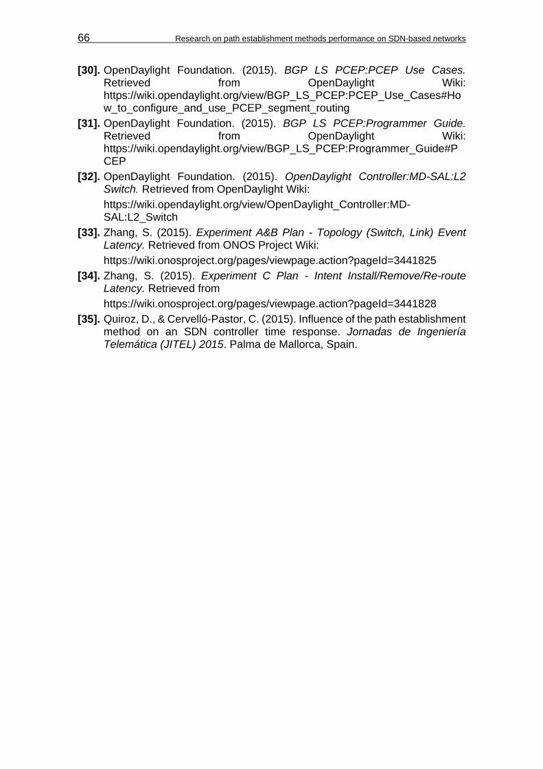
66 Research on path establishment methods performance on SDN-based networks
[30]. OpenDaylight Foundation. (2015). BGP LS PCEP:PCEP Use Cases. Retrieved from OpenDaylight Wiki: https://wiki.opendaylight.org/view/BGP_LS_PCEP:PCEP_Use_Cases#How_to_configure_and_use_PCEP_segment_routing
[31]. OpenDaylight Foundation. (2015). BGP LS PCEP:Programmer Guide. Retrieved from OpenDaylight Wiki: https://wiki.opendaylight.org/view/BGP_LS_PCEP:Programmer_Guide#PCEP
[32]. OpenDaylight Foundation. (2015). OpenDaylight Controller:MD-SAL:L2 Switch. Retrieved from OpenDaylight Wiki:
https://wiki.opendaylight.org/view/OpenDaylight_Controller:MD-SAL:L2_Switch
[33]. Zhang, S. (2015). Experiment A&B Plan - Topology (Switch, Link) Event Latency. Retrieved from ONOS Project Wiki:
https://wiki.onosproject.org/pages/viewpage.action?pageId=3441825
[34]. Zhang, S. (2015). Experiment C Plan - Intent Install/Remove/Re-route Latency. Retrieved from
https://wiki.onosproject.org/pages/viewpage.action?pageId=3441828
[35]. Quiroz, D., & Cervelló-Pastor, C. (2015). Influence of the path establishment method on an SDN controller time response. Jornadas de Ingeniería Telemática (JITEL) 2015. Palma de Mallorca, Spain.
Acronyms 67
ACRONYMS
ACL Access List
ADJ-SID Adjacency Segment ID
API Application Programmable Interface
ARP Address Resolution Protocol
BGP Border Gateway Protocol
CAPEX Capital Expenditure
CI Confidence Interval
CLI Command Line Interface
CPU Central Processing Unit
DPID Datapath Identifier
DSCP Differentiated Services Code Point
ECMP Equal Cost Multipath
EGP Exterior Gateway Protocol
FIB Forwarding Information Base
FRR Fast Reroute
GUI Graphical User Interface
ICMP Internet Control Message Protocol
IETF Internet Engineering Task Force
IGP Interior Gateway Protocol
IP Internet Protocol
IPFRR IP Fast Reroute
ISIS Intermediate System-to-Intermediate System
ITU International Telecommunication Union
JDK Java Development Kit
LDP Label Distribution Protocol
LFIB Label Forwarding Information Base
LIB Label Information Base
LLDP Link Layer Discovery Protocol
LSP Label Switched Path
LSR Label Switching Router
MAC Media Access Control
MGEN Multi-Generator
68 Research on path establishment methods performance on SDN-based networks
MPLS Multiprotocol Label Switching
NBI Northbound Interface
NIC Network Interface Card
NODE-SID Node Segment ID
NOS Network Operating System
OAM Operations, Administration and Maintenance
ONOS Open Network Operating System
OPEX Operational Expenditures
OS Operating System
OSGi Open Services Gateway initiative
OSPF Open Shortest Path First
PBB Provider Backbone Bridge
PCEP Path Computation Element Protocol
PF Proactive Forwarding
PHP Penultimate Hop Popping
QoE Quality of Experience
QoS Quality of Service
RAM Random Access Memory
RTT Round-Trip Time
SDN Software Defined Networking
SID Segment Identifier
SLA Service Level Agreement
SPF Shortest Path First
SPRING Source Packet Routing In Networking working group
SR Segment Routing
TCP Transmission Control Protocol
TLS Transport Layer Security
TTL Time To Live
UDP User Datagram Protocol
VLAN Virtual Local Area Network
VM Virtual Machine
VoIP Voice over IP
VPN Virtual Private Network
WAN Wide Area Network
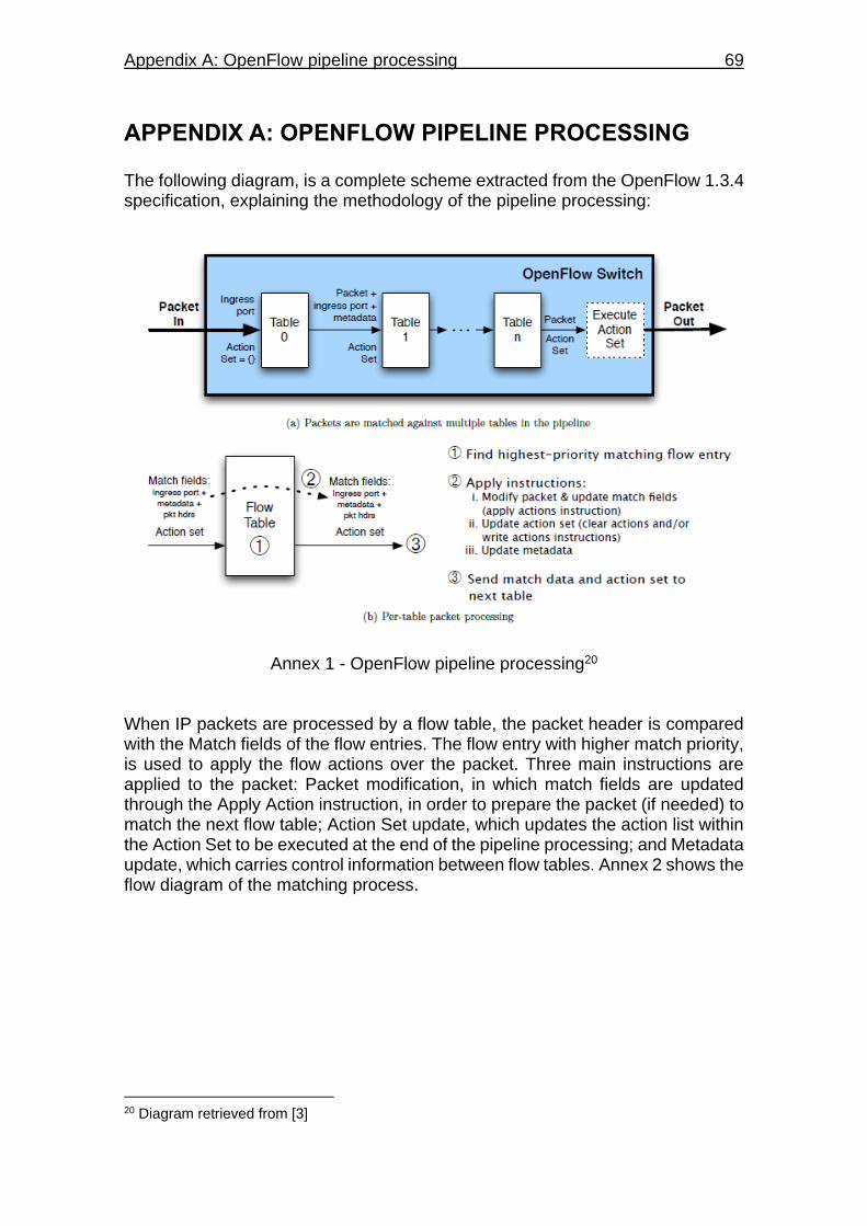
Appendix A: OpenFlow pipeline processing 69
APPENDIX A: OPENFLOW PIPELINE PROCESSING The following diagram, is a complete scheme extracted from the OpenFlow 1.3.4 specification, explaining the methodology of the pipeline processing:
Annex 1 - OpenFlow pipeline processing20 When IP packets are processed by a flow table, the packet header is compared with the Match fields of the flow entries. The flow entry with higher match priority, is used to apply the flow actions over the packet. Three main instructions are applied to the packet: Packet modification, in which match fields are updated through the Apply Action instruction, in order to prepare the packet (if needed) to match the next flow table; Action Set update, which updates the action list within the Action Set to be executed at the end of the pipeline processing; and Metadata update, which carries control information between flow tables. Annex 2 shows the flow diagram of the matching process.
20 Diagram retrieved from [3]
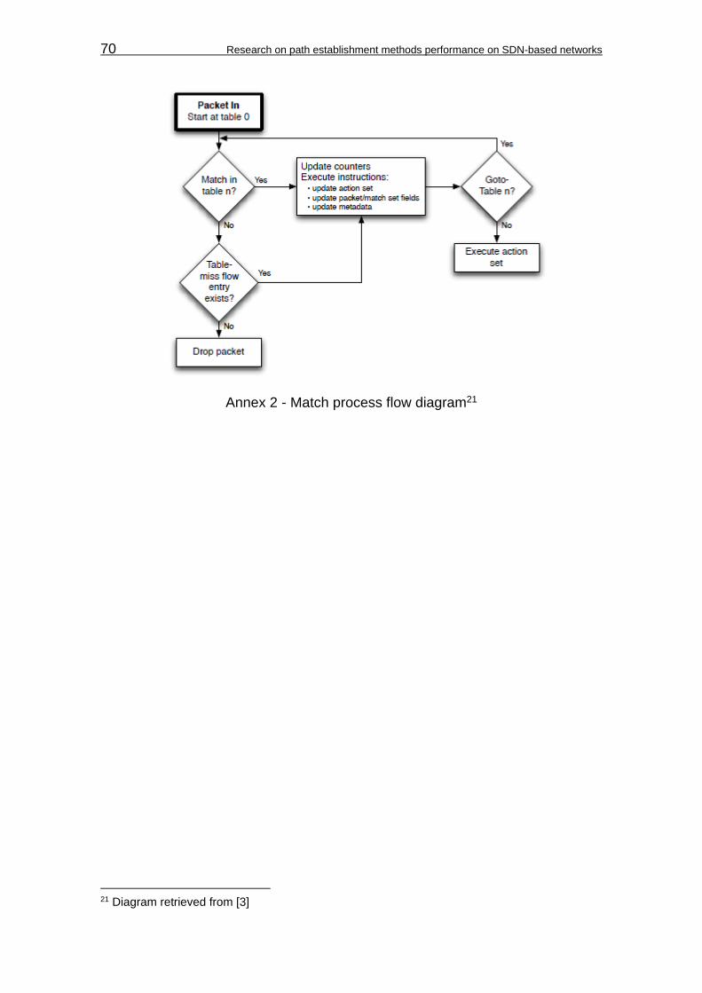
70 Research on path establishment methods performance on SDN-based networks
Annex 2 - Match process flow diagram21
21 Diagram retrieved from [3]

Appendix B: Network topology scripts 71
APPENDIX B: NETWORK TOPOLOGY SCRIPTS The following codes, represent the scripts used to configure the Proactive Forwarding, and Segment Routing topologies on Mininet:
"""
10 switch, 2 hosts, 14 links for Proactive Forwarding
"""
from mininet.topo import Topo
class SRTopo( Topo ):
def __init__( self ):
"Create custom topo."
# Initialize topology
Topo.__init__( self )
# Add hosts and switches
host1 = self.addHost( 'h1' )
host2 = self.addHost( 'h2' )
s1 = self.addSwitch('s1')
s2 = self.addSwitch('s2')
s3 = self.addSwitch('s3')
s4 = self.addSwitch('s4')
s5 = self.addSwitch('s5')
s6 = self.addSwitch('s6')
s7 = self.addSwitch('s7')
s8 = self.addSwitch('s8')
s9 = self.addSwitch('s9')
s10 = self.addSwitch('s10')
# Add links for hosts
self.addLink( host1, s1)
self.addLink( host2, s6)
# Add links between switches
self.addLink(s1, s2)
self.addLink(s2, s3)
self.addLink(s3, s4)
self.addLink(s4, s5)
self.addLink(s5, s6)
self.addLink(s6, s7)
self.addLink(s7, s8)
self.addLink(s8, s9)
self.addLink(s9, s10)
self.addLink(s10, s1)
self.addLink(s3, s9)
self.addLink(s4, s8)
topos = { 'mytopo': ( lambda: SRTopo() ) }
Code 1 - Proactive Forwarding script. TopoTestPF.py
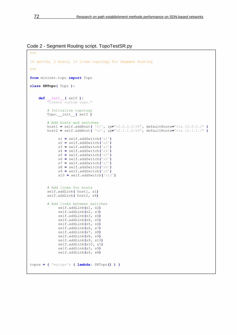
72 Research on path establishment methods performance on SDN-based networks
"""
10 switch, 2 hosts, 14 links topology for Segment Routing
"""
from mininet.topo import Topo
class SRTopo( Topo ):
def __init__( self ):
"Create custom topo."
# Initialize topology
Topo.__init__( self )
# Add hosts and switches
host1 = self.addHost( 'h1', ip="10.0.0.5/24", defaultRoute="via 10.0.0.1" )
host2 = self.addHost( 'h2', ip="10.1.1.5/24", defaultRoute="via 10.1.1.1" )
s1 = self.addSwitch('s1')
s2 = self.addSwitch('s2')
s3 = self.addSwitch('s3')
s4 = self.addSwitch('s4')
s5 = self.addSwitch('s5')
s6 = self.addSwitch('s6')
s7 = self.addSwitch('s7')
s8 = self.addSwitch('s8')
s9 = self.addSwitch('s9')
s10 = self.addSwitch('s10')
# Add links for hosts
self.addLink( host1, s1)
self.addLink( host2, s6)
# Add links between switches
self.addLink(s1, s2)
self.addLink(s2, s3)
self.addLink(s3, s4)
self.addLink(s4, s5)
self.addLink(s5, s6)
self.addLink(s6, s7)
self.addLink(s7, s8)
self.addLink(s8, s9)
self.addLink(s9, s10)
self.addLink(s10, s1)
self.addLink(s3, s9)
self.addLink(s4, s8)
topos = { 'mytopo': ( lambda: SRTopo() ) }
Code 2 - Segment Routing script. TopoTestSR.py
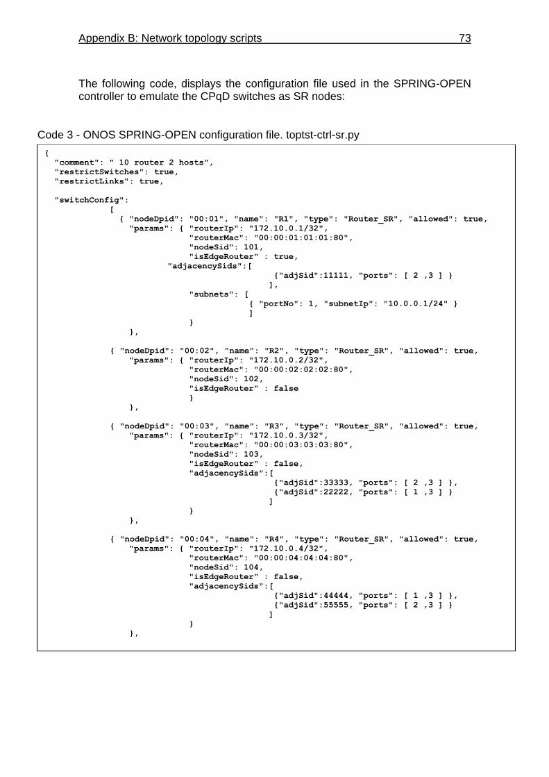
Appendix B: Network topology scripts 73
The following code, displays the configuration file used in the SPRING-OPEN controller to emulate the CPqD switches as SR nodes:
{
"comment": " 10 router 2 hosts",
"restrictSwitches": true,
"restrictLinks": true,
"switchConfig":
[
{ "nodeDpid": "00:01", "name": "R1", "type": "Router_SR", "allowed": true,
"params": { "routerIp": "172.10.0.1/32",
"routerMac": "00:00:01:01:01:80",
"nodeSid": 101,
"isEdgeRouter" : true,
"adjacencySids":[
{"adjSid":11111, "ports": [ 2 ,3 ] }
],
"subnets": [
{ "portNo": 1, "subnetIp": "10.0.0.1/24" }
]
}
},
{ "nodeDpid": "00:02", "name": "R2", "type": "Router_SR", "allowed": true,
"params": { "routerIp": "172.10.0.2/32",
"routerMac": "00:00:02:02:02:80",
"nodeSid": 102,
"isEdgeRouter" : false
}
},
{ "nodeDpid": "00:03", "name": "R3", "type": "Router_SR", "allowed": true,
"params": { "routerIp": "172.10.0.3/32",
"routerMac": "00:00:03:03:03:80",
"nodeSid": 103,
"isEdgeRouter" : false,
"adjacencySids":[
{"adjSid":33333, "ports": [ 2 ,3 ] },
{"adjSid":22222, "ports": [ 1 ,3 ] }
]
}
},
{ "nodeDpid": "00:04", "name": "R4", "type": "Router_SR", "allowed": true,
"params": { "routerIp": "172.10.0.4/32",
"routerMac": "00:00:04:04:04:80",
"nodeSid": 104,
"isEdgeRouter" : false,
"adjacencySids":[
{"adjSid":44444, "ports": [ 1 ,3 ] },
{"adjSid":55555, "ports": [ 2 ,3 ] }
]
}
},
Code 3 - ONOS SPRING-OPEN configuration file. toptst-ctrl-sr.py
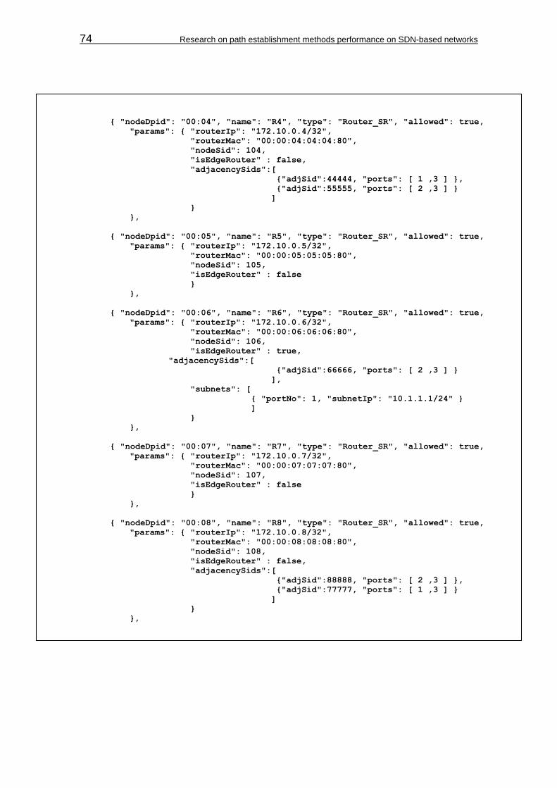
74 Research on path establishment methods performance on SDN-based networks
{ "nodeDpid": "00:04", "name": "R4", "type": "Router_SR", "allowed": true,
"params": { "routerIp": "172.10.0.4/32",
"routerMac": "00:00:04:04:04:80",
"nodeSid": 104,
"isEdgeRouter" : false,
"adjacencySids":[
{"adjSid":44444, "ports": [ 1 ,3 ] },
{"adjSid":55555, "ports": [ 2 ,3 ] }
]
}
},
{ "nodeDpid": "00:05", "name": "R5", "type": "Router_SR", "allowed": true,
"params": { "routerIp": "172.10.0.5/32",
"routerMac": "00:00:05:05:05:80",
"nodeSid": 105,
"isEdgeRouter" : false
}
},
{ "nodeDpid": "00:06", "name": "R6", "type": "Router_SR", "allowed": true,
"params": { "routerIp": "172.10.0.6/32",
"routerMac": "00:00:06:06:06:80",
"nodeSid": 106,
"isEdgeRouter" : true,
"adjacencySids":[
{"adjSid":66666, "ports": [ 2 ,3 ] }
],
"subnets": [
{ "portNo": 1, "subnetIp": "10.1.1.1/24" }
]
}
},
{ "nodeDpid": "00:07", "name": "R7", "type": "Router_SR", "allowed": true,
"params": { "routerIp": "172.10.0.7/32",
"routerMac": "00:00:07:07:07:80",
"nodeSid": 107,
"isEdgeRouter" : false
}
},
{ "nodeDpid": "00:08", "name": "R8", "type": "Router_SR", "allowed": true,
"params": { "routerIp": "172.10.0.8/32",
"routerMac": "00:00:08:08:08:80",
"nodeSid": 108,
"isEdgeRouter" : false,
"adjacencySids":[
{"adjSid":88888, "ports": [ 2 ,3 ] },
{"adjSid":77777, "ports": [ 1 ,3 ] }
]
}
},

Appendix B: Network topology scripts 75
{ "nodeDpid": "00:09", "name": "R9", "type": "Router_SR", "allowed": true,
"params": { "routerIp": "172.10.0.9/32",
"routerMac": "00:00:09:09:09:80",
"nodeSid": 109,
"isEdgeRouter" : false,
"adjacencySids":[
{"adjSid":99999, "ports": [ 1 ,3 ] },
{"adjSid":10101, "ports": [ 2 ,3 ] }
]
}
},
{ "nodeDpid": "00:0a", "name": "R10", "type": "Router_SR", "allowed": true,
"params": { "routerIp": "172.10.0.10/32",
"routerMac": "00:00:10:10:10:80",
"nodeSid": 110,
"isEdgeRouter" : false
}
}
],
"linkConfig":[
{ "type": "pktLink", "allowed": true,
"nodeDpid1": "01", "nodeDpid2": "02",
"params": { "port1": 2, "port2": 1 }
},
{ "type": "pktLink", "allowed": true,
"nodeDpid1": "02", "nodeDpid2": "03",
"params": { "port1": 2, "port2": 1 }
},
{ "type": "pktLink", "allowed": true,
"nodeDpid1": "03", "nodeDpid2": "04",
"params": { "port1": 2, "port2": 1 }
},
{ "type": "pktLink", "allowed": true, "nodeDpid1": "03", "nodeDpid2": "09",
"params": { "port1": 3, "port2": 3 }
},
{ "type": "pktLink", "allowed": true,
"nodeDpid1": "04", "nodeDpid2": "08",
"params": { "port1": 3, "port2": 3 }
},
{ "type": "pktLink", "allowed": true,
"nodeDpid1": "04", "nodeDpid2": "05",
"params": { "port1": 2, "port2": 1 }
},
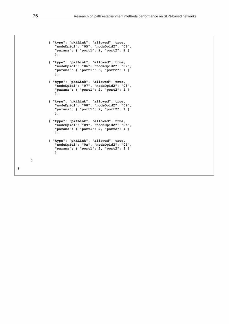
76 Research on path establishment methods performance on SDN-based networks
{ "type": "pktLink", "allowed": true,
"nodeDpid1": "05", "nodeDpid2": "06",
"params": { "port1": 2, "port2": 2 }
},
{ "type": "pktLink", "allowed": true,
"nodeDpid1": "06", "nodeDpid2": "07",
"params": { "port1": 3, "port2": 1 }
},
{ "type": "pktLink", "allowed": true,
"nodeDpid1": "07", "nodeDpid2": "08",
"params": { "port1": 2, "port2": 1 }
},
{ "type": "pktLink", "allowed": true,
"nodeDpid1": "08", "nodeDpid2": "09",
"params": { "port1": 2, "port2": 1 }
},
{ "type": "pktLink", "allowed": true,
"nodeDpid1": "09", "nodeDpid2": "0a",
"params": { "port1": 2, "port2": 1 }
},
{ "type": "pktLink", "allowed": true,
"nodeDpid1": "0a", "nodeDpid2": "01",
"params": { "port1": 2, "port2": 3 }
}
]
}
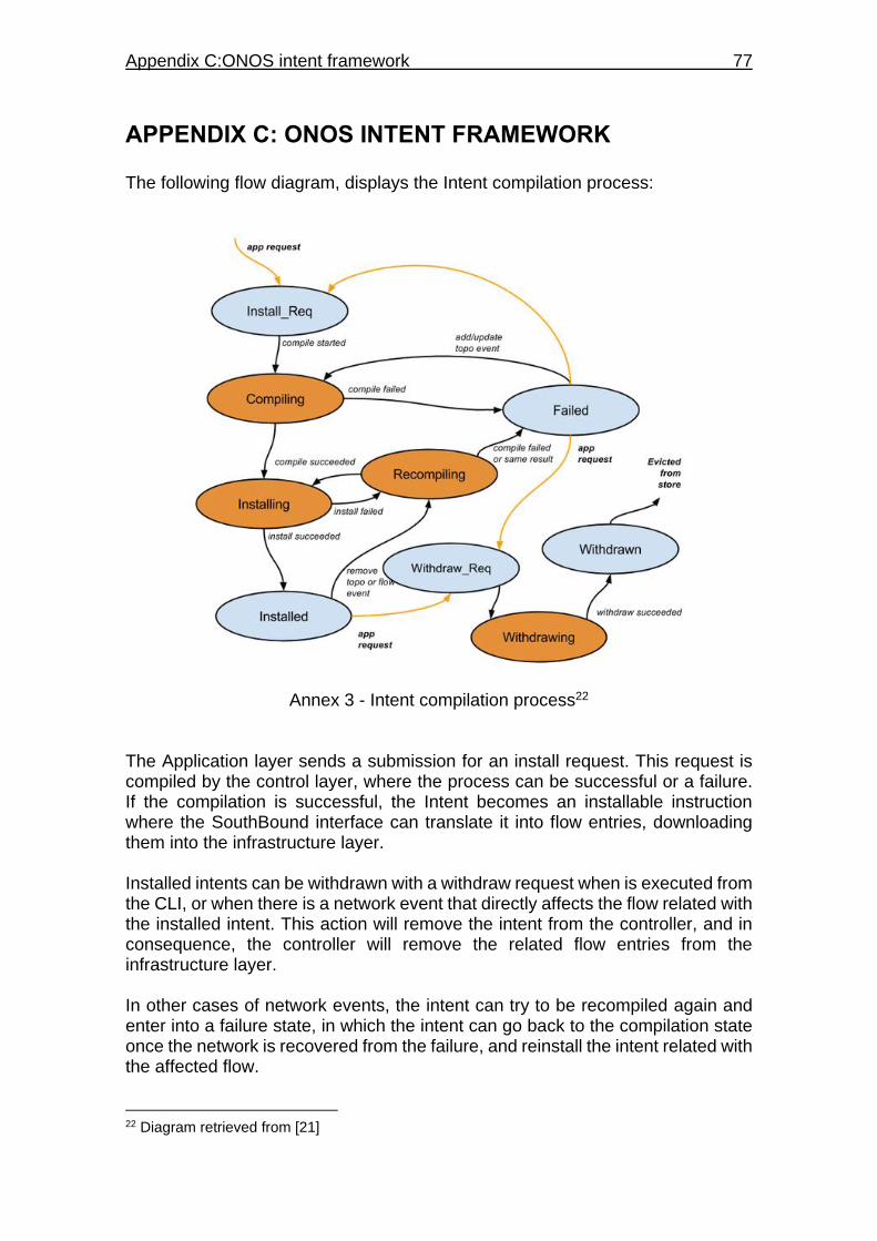
Appendix C:ONOS intent framework 77
APPENDIX C: ONOS INTENT FRAMEWORK The following flow diagram, displays the Intent compilation process:
Annex 3 - Intent compilation process22 The Application layer sends a submission for an install request. This request is compiled by the control layer, where the process can be successful or a failure. If the compilation is successful, the Intent becomes an installable instruction where the SouthBound interface can translate it into flow entries, downloading them into the infrastructure layer. Installed intents can be withdrawn with a withdraw request when is executed from the CLI, or when there is a network event that directly affects the flow related with the installed intent. This action will remove the intent from the controller, and in consequence, the controller will remove the related flow entries from the infrastructure layer. In other cases of network events, the intent can try to be recompiled again and enter into a failure state, in which the intent can go back to the compilation state once the network is recovered from the failure, and reinstall the intent related with the affected flow.
22 Diagram retrieved from [21]
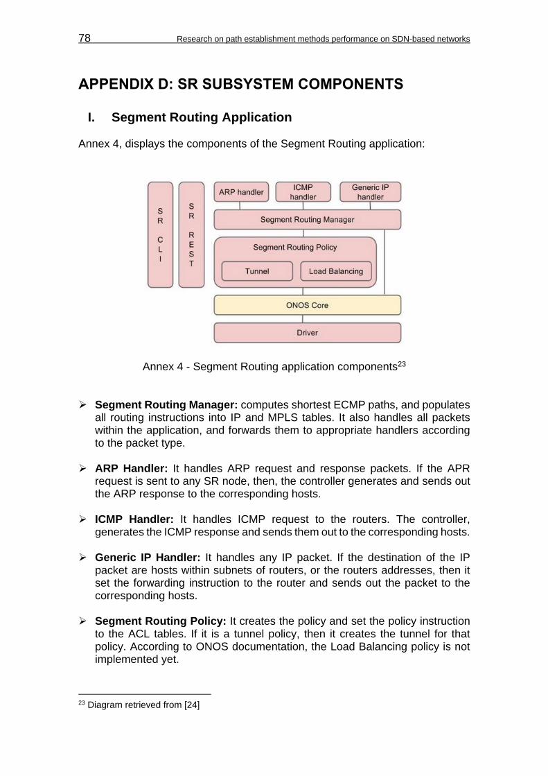
78 Research on path establishment methods performance on SDN-based networks
APPENDIX D: SR SUBSYSTEM COMPONENTS
I. Segment Routing Application Annex 4, displays the components of the Segment Routing application:
Annex 4 - Segment Routing application components23 Segment Routing Manager: computes shortest ECMP paths, and populates
all routing instructions into IP and MPLS tables. It also handles all packets within the application, and forwards them to appropriate handlers according to the packet type.
ARP Handler: It handles ARP request and response packets. If the APR
request is sent to any SR node, then, the controller generates and sends out the ARP response to the corresponding hosts.
ICMP Handler: It handles ICMP request to the routers. The controller,
generates the ICMP response and sends them out to the corresponding hosts. Generic IP Handler: It handles any IP packet. If the destination of the IP
packet are hosts within subnets of routers, or the routers addresses, then it set the forwarding instruction to the router and sends out the packet to the corresponding hosts.
Segment Routing Policy: It creates the policy and set the policy instruction
to the ACL tables. If it is a tunnel policy, then it creates the tunnel for that policy. According to ONOS documentation, the Load Balancing policy is not implemented yet.
23 Diagram retrieved from [24]
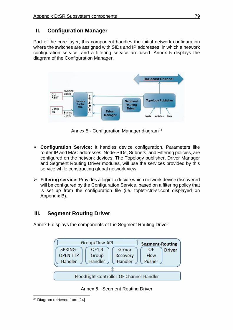
Appendix D:SR Subsystem components 79
II. Configuration Manager Part of the core layer, this component handles the initial network configuration where the switches are assigned with SIDs and IP addresses, in which a network configuration service, and a filtering service are used. Annex 5 displays the diagram of the Configuration Manager.
Annex 5 - Configuration Manager diagram24 Configuration Service: It handles device configuration. Parameters like
router IP and MAC addresses, Node-SIDs, Subnets, and Filtering policies, are configured on the network devices. The Topology publisher, Driver Manager and Segment Routing Driver modules, will use the services provided by this service while constructing global network view.
Filtering service: Provides a logic to decide which network device discovered
will be configured by the Configuration Service, based on a filtering policy that is set up from the configuration file (i.e. toptst-ctrl-sr.conf displayed on Appendix B).
III. Segment Routing Driver Annex 6 displays the components of the Segment Routing Driver:
Annex 6 - Segment Routing Driver
24 Diagram retrieved from [24]

80 Research on path establishment methods performance on SDN-based networks
OF 1.3 Group Handler25 At startup, pre-populates the OF 1.3 groups in all the Segment Routers. There are two types of groups that Segment Routing driver creates in the switches: Indirect and Select groups. Indirect groups, their main advantage is that when many, many routes (IP dst prefixes) have a Next-Hop that requires the router to send the packet out of the same port with or without same label, it is easier to envelop that port and/or label in an indirect group. Note that these Groups are only created on ports that are connected to other routers (and not an L2 domain). Thus the Dst-MAC is always known to the controller, since it is the router-MAC of another router in the Segment Routing domain. Also Note that this group does NOT push or set VLAN tags, as these groups are meant to be used between routers within the Segment Routing cloud. Since the Segment Routing cloud does not use VLANs, such actions are not needed. This group will contain a single bucket, with the following possible actions:
Set Dst MAC address (next hop router-mac address) Set Src MAC address (this router’s router-mac address) At ingress router
o Push MPLS header with ethtype as IP and mpls label o Copy TTL out o Decrement MPLS TTL
Output to port (connected to another Router) Select groups, will have one or more buckets, that each point to actions of an Indirect group or point to another group (in case of group chaining). Note that this group definition does not distinguish between hashes made on IPv4 packets, and hashes made on packets with an MPLS label stack. It is understood that the switch makes the best hash decision possible with the given information.
By default all ports connected to the same neighbor router will be part of the same ECMP group.
In addition, ECMP groups will be created for all possible combinations of
neighbor routers.
Group Recovery Handler26 This component of Segment Routing driver handles network element failures and ONOS controller failure.
25 Content retrieved from [24] 26 Content retrieved from [24]

Appendix D:SR Subsystem components 81
Controller failures: When a ONOS instance restarts and switches connects back to that controller, the Segment Routing driver performs an audit of existing Groups in the switch so that it pushes only the missing groups in to the switch.
Network element failures: When a port of a switch fails, this component
determine all the group buckets where the failed port is part of and perform a OF "GroupMod.MODIFY" operation on all such groups to remove those buckets. As a result, there may be some empty groups (groups with no buckets) lying in the switch. Similarly when the port is UP again, this component determines all the impacted groups and perform a OF "GroupMod.MODIFY" operation on all such groups to add those buckets with the recovered ports.
OF Message Pusher This component builds OpenFlow messages from the provided match action operation entry objects from higher layers, and sends them down into the network devices.
Driver API This API provides the following APIs with the upper layer: createGroup: builds an individual or a sequence of groups, and return the
topmost group ID to the upper layers. removeGroup: removes groups associated with a given ID and group
sequence (if any). pushFlow: Executes the OF Message Pusher component.

82 Research on path establishment methods performance on SDN-based networks
APPENDIX E: SOFTWARE INSTALLATION
I. ONOS Blackbird installation
Oracle Java 8 JDK installation
$ sudo apt-get install software-properties-common –y
$ sudo add-apt-repository ppa:webupd8team/java –y
$ sudo apt-get update
$ sudo apt-get install oracle-java8-installer oracle-java8-set-default –y
o It will prompt a license agreement
o Accept the license agreement
Apache Karaf 3.0.2 and Maven 3.2.3 installation
Create to directories called Downloads and Applications in the home directory (in this case /home/quirozd). The Downloads directory is used to save the tar files of Apache Maven and Karaf downloaded from the internet, and the Applications directory is used to save the content extracted from the tar files.
$ sudo mkdir Downloads Applications
$ cd Downloads
$ sudo wget http://download.nextag.com/apache/karaf/3.0.2/apache-karaf-3.0.2.tar.gz
$ sudo wget https://archive.apache.org/dist/maven/maven-3/3.2.3/binaries/apache-maven-3.2.3-bin.tar.gz
Verify that both tar files are downloaded
o $ ls
$ sudo tar -zxvf apache-karaf-3.0.2.tar.gz -C ../Applications/
$ sudo tar -zxvf apache-maven-3.2.3-bin.tar.gz -C ../Applications/
Verify that the content of both tar files have been extracted on the
Applications directory.
o $ cd /Applications
o $ ls
Annex 7 - Apache Karaf and Maven verification
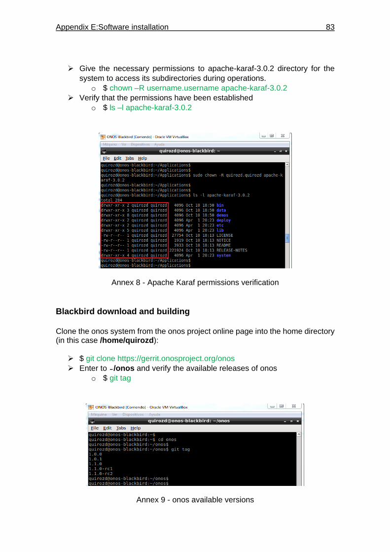
Appendix E:Software installation 83
Give the necessary permissions to apache-karaf-3.0.2 directory for the
system to access its subdirectories during operations.
o $ chown –R username.username apache-karaf-3.0.2
Verify that the permissions have been established
o $ ls –l apache-karaf-3.0.2
Annex 8 - Apache Karaf permissions verification
Blackbird download and building
Clone the onos system from the onos project online page into the home directory (in this case /home/quirozd):
$ git clone https://gerrit.onosproject.org/onos
Enter to /onos and verify the available releases of onos
o $ git tag
Annex 9 - onos available versions

84 Research on path establishment methods performance on SDN-based networks
ONOS Blackbird is represented from release 1.1.0, in this case the latest version of this release is used (1.1.0-rc2):
$ git checkout –b 1.1.0-rc2 1.1.0-rc2
Verify that the onos version is correct by checking the file /onos/pom.xml
Annex 10 - ONOS version verification
$ cd ..
Before building Blackbird, it is necessary to set up Ubuntu environment variables to add the necessary path that the system will use to build and access the controller. Instead of adding them manually, the file /onos/tools/dev/bash_profile represent a script to add them automatically.
Verify the file /onos/tools/dev/bash_profile to ensure that the correct
versions of Apache Karaf and Apache Maven will be called.
Annex 11 - Apache Karaf and Maven version verification
Edit the file /.bashrc to add the following line at the end
o . /onos/tools/dev/bash_profile
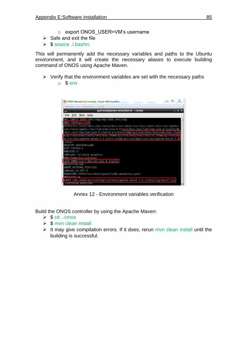
Appendix E:Software installation 85
o export ONOS_USER=VM’s username
Safe and exit the file
$ source ./.bashrc
This will permanently add the necessary variables and paths to the Ubuntu environment, and it will create the necessary aliases to execute building command of ONOS using Apache Maven.
Verify that the environment variables are set with the necessary paths
o $ env
Annex 12 - Environment variables verification Build the ONOS controller by using the Apache Maven:
$ cd /onos
$ mvn clean install
It may give compilation errors. If it does, rerun mvn clean install until the
building is successful.

86 Research on path establishment methods performance on SDN-based networks
Annex 13 - Successful system building Edit the file /Applications/apache-karaf-3.0.2/etc/org.apache.karaf.features.cfg in order to initialize the controller with the desired features and applications.
Add the following lines on the file
o On featuresRepositories
mvn:org.onosproject/onos-features/1.1.0-rc2/xml/features
o On featuresBoot
webconsole,onos-api,onos-core-trivial,onos-cli,onos-
rest,onos-gui,onos-openflow,onos-app-fwd,onos-app-
proxyarp,onos-app-mobility
Save and exit the file
$ cd - - (to go back to home directory)
Start the ONOS console through Apache Karaf
o $ karaf clean (when initializing for the first time to take effect the
features added to the configuration file)
o $ karaf (for regular console start)
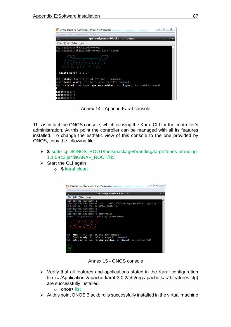
Appendix E:Software installation 87
Annex 14 - Apache Karaf console This is in fact the ONOS console, which is using the Karaf CLI for the controller’s administration. At this point the controller can be managed with all its features installed. To change the esthetic view of this console to the one provided by ONOS, copy the following file:
$ sudo cp $ONOS_ROOT/tools/package/branding/target/onos-branding-
1.1.0-rc2.jar $KARAF_ROOT/lib/
Start the CLI again
o $ karaf clean
Annex 15 - ONOS console
Verify that all features and applications stated in the Karaf configuration
file ( /Applications/apache-karaf-3.0.2/etc/org.apache.karaf.features.cfg)
are successfully installed
o onos˃ list
At this point ONOS Blackbird is successfully installed in the virtual machine
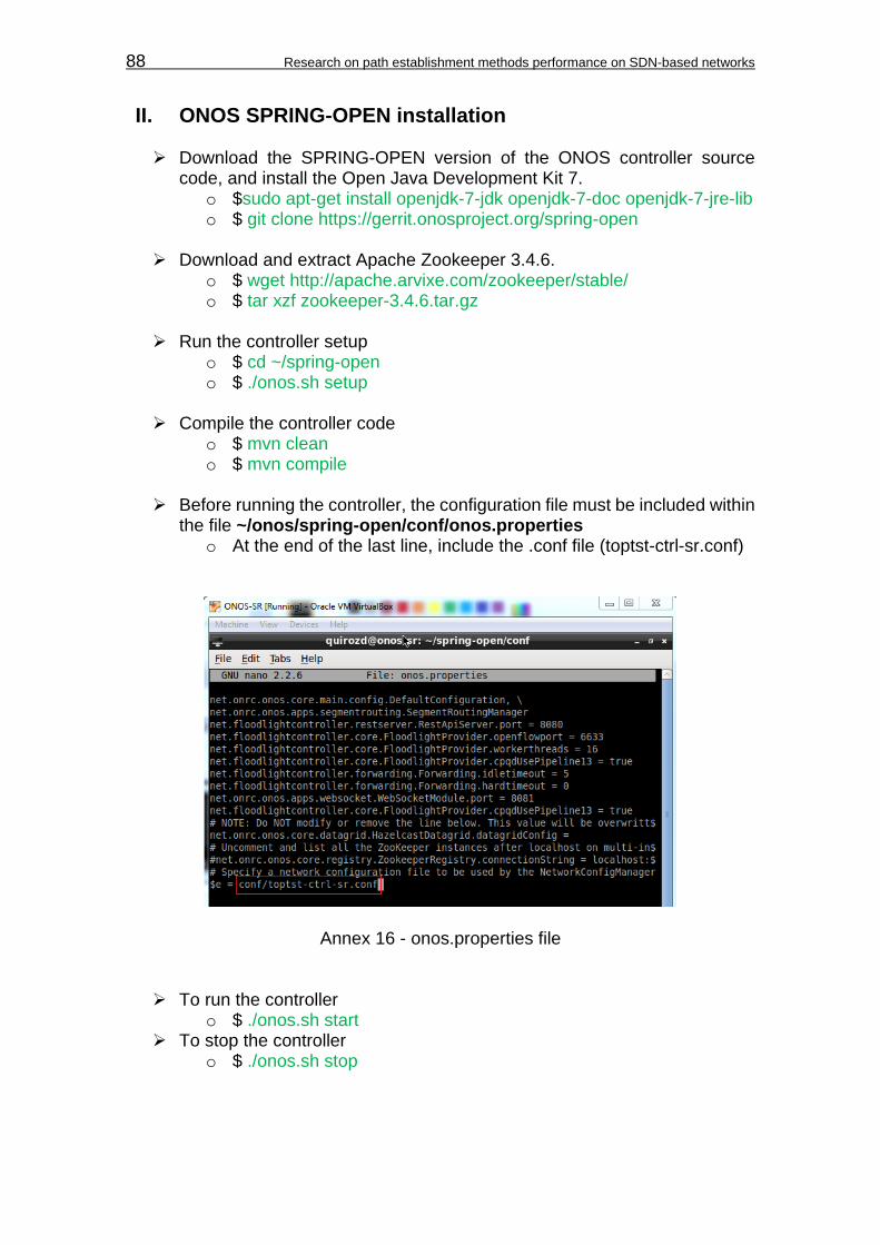
88 Research on path establishment methods performance on SDN-based networks
II. ONOS SPRING-OPEN installation
Download the SPRING-OPEN version of the ONOS controller source code, and install the Open Java Development Kit 7.
o $sudo apt-get install openjdk-7-jdk openjdk-7-doc openjdk-7-jre-lib o $ git clone https://gerrit.onosproject.org/spring-open
Download and extract Apache Zookeeper 3.4.6.
o $ wget http://apache.arvixe.com/zookeeper/stable/ o $ tar xzf zookeeper-3.4.6.tar.gz
Run the controller setup
o $ cd ~/spring-open o $ ./onos.sh setup
Compile the controller code
o $ mvn clean o $ mvn compile
Before running the controller, the configuration file must be included within
the file ~/onos/spring-open/conf/onos.properties o At the end of the last line, include the .conf file (toptst-ctrl-sr.conf)
Annex 16 - onos.properties file
To run the controller o $ ./onos.sh start
To stop the controller o $ ./onos.sh stop
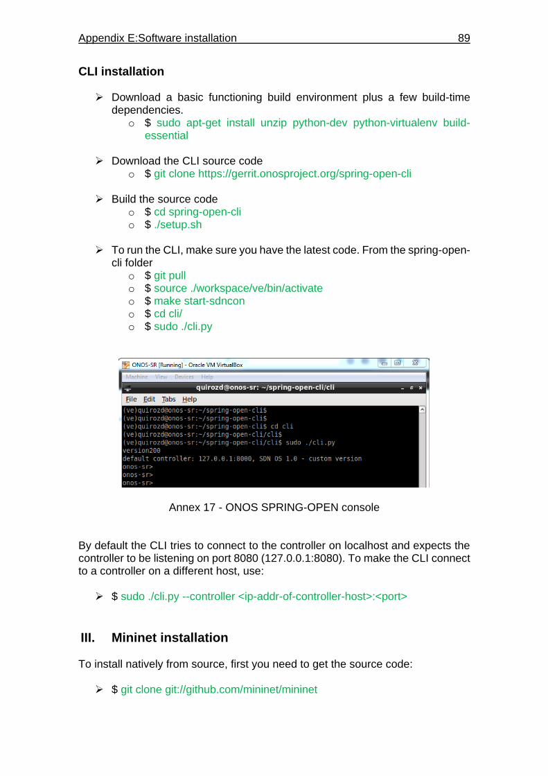
Appendix E:Software installation 89
CLI installation
Download a basic functioning build environment plus a few build-time dependencies.
o $ sudo apt-get install unzip python-dev python-virtualenv build-essential
Download the CLI source code
o $ git clone https://gerrit.onosproject.org/spring-open-cli
Build the source code o $ cd spring-open-cli o $ ./setup.sh
To run the CLI, make sure you have the latest code. From the spring-open-
cli folder o $ git pull o $ source ./workspace/ve/bin/activate o $ make start-sdncon o $ cd cli/ o $ sudo ./cli.py
Annex 17 - ONOS SPRING-OPEN console By default the CLI tries to connect to the controller on localhost and expects the controller to be listening on port 8080 (127.0.0.1:8080). To make the CLI connect to a controller on a different host, use:
$ sudo ./cli.py --controller <ip-addr-of-controller-host>:<port>
III. Mininet installation To install natively from source, first you need to get the source code:
$ git clone git://github.com/mininet/mininet
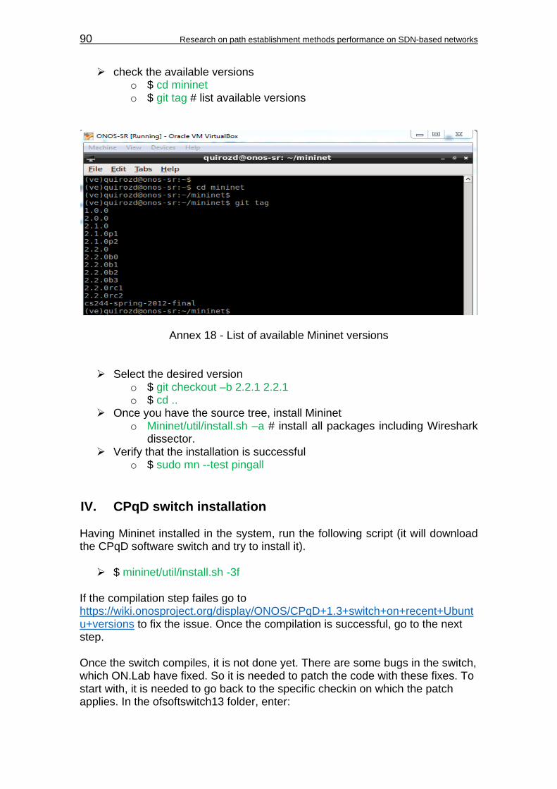
90 Research on path establishment methods performance on SDN-based networks
check the available versions o $ cd mininet o $ git tag # list available versions
Annex 18 - List of available Mininet versions
Select the desired version o $ git checkout –b 2.2.1 2.2.1 o $ cd ..
Once you have the source tree, install Mininet o Mininet/util/install.sh –a # install all packages including Wireshark
dissector. Verify that the installation is successful
o $ sudo mn --test pingall
IV. CPqD switch installation Having Mininet installed in the system, run the following script (it will download the CPqD software switch and try to install it).
$ mininet/util/install.sh -3f If the compilation step failes go to https://wiki.onosproject.org/display/ONOS/CPqD+1.3+switch+on+recent+Ubuntu+versions to fix the issue. Once the compilation is successful, go to the next step. Once the switch compiles, it is not done yet. There are some bugs in the switch, which ON.Lab have fixed. So it is needed to patch the code with these fixes. To start with, it is needed to go back to the specific checkin on which the patch applies. In the ofsoftswitch13 folder, enter:

Appendix E:Software installation 91
$ git checkout -b cpqd-spring 36738aeb3501f66fb382e7b59138c88e8843b19c
Execute “git log” to verify the commit
Annex 19 - CPqD commit verification
Download the patch o $ wget
https://wiki.onosproject.org/download/attachments/2130895/patchfile-cpqd
Apply the patch
o $ patch -p0 < patchfile-cpqd
Execute “git status” to verify the patch
Annex 20 - Patch verification
Finally, compile again o $ make o $ sudo make install
To use mininet with CPqD, to start the desired topology, execute: $ sudo mn –custom mininet/custom/file.py --topo mytopo --switch user --
controller=remote,ip=<IP address˃,port=6633 # being file.py the python script for the topology (TopoTestPF.py or TopoTestSR.py)
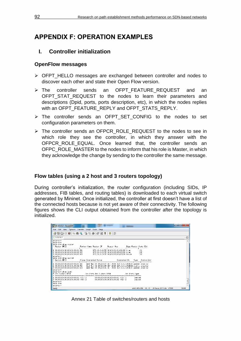
92 Research on path establishment methods performance on SDN-based networks
APPENDIX F: OPERATION EXAMPLES
I. Controller initialization
OpenFlow messages OFPT_HELLO messages are exchanged between controller and nodes to
discover each other and state their Open Flow version.
The controller sends an OFPT_FEATURE_REQUEST and an
OFPT_STAT_REQUEST to the nodes to learn their parameters and
descriptions (Dpid, ports, ports description, etc), in which the nodes replies
with an OFPT_FEATURE_REPLY and OFPT_STATS_REPLY.
The controller sends an OFPT_SET_CONFIG to the nodes to set
configuration parameters on them.
The controller sends an OFPCR_ROLE_REQUEST to the nodes to see in
which role they see the controller, in which they answer with the
OFPCR_ROLE_EQUAL. Once learned that, the controller sends an
OFPC_ROLE_MASTER to the nodes to inform that his role is Master, in which
they acknowledge the change by sending to the controller the same message.
Flow tables (using a 2 host and 3 routers topology) During controller’s initialization, the router configuration (including SIDs, IP addresses, FIB tables, and routing tables) is downloaded to each virtual switch generated by Mininet. Once initialized, the controller at first doesn’t have a list of the connected hosts because is not yet aware of their connectivity. The following figures shows the CLI output obtained from the controller after the topology is initialized.
Annex 21 Table of switches/routers and hosts
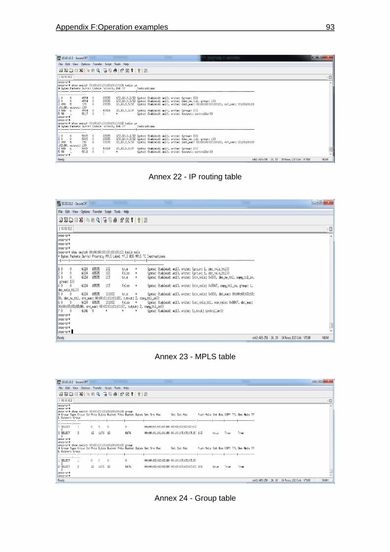
Appendix F:Operation examples 93
Annex 22 - IP routing table
Annex 23 - MPLS table
Annex 24 - Group table

94 Research on path establishment methods performance on SDN-based networks
Observations: The routing table depends on a series of instructions to forward packets at
layer 2 and 1 levels, based on a group configuration that will determine the
path that each packet will follow.
Each group represents an ECMP group where a set of links can be defined
with an instruction destined for each of them. This instructions determine
when a packet labeling is necessary for the traffic going out through a certain
port.
The MPLS table will show the FIB saved under each device, and the labels
will be related to the ECMP groups depending on the location of the router
with SID equals to the label. For neighbor routers, they will be marked as POP
in order to do penultimate hop popping on packages heading to those devices.
II. Link behavior on Segment Routing For this test, the following topology was used:
Annex 25 - 2 host, 3 routers topology In this topology, it is tested the behavior of redundant links and how the network respond during a link failure.

Appendix F:Operation examples 95
Multipath links Observations: The redundant links that interconnects the same 2 devices, are set under the
same ECMP group.
The redundant links load balance the traffic passing through them by using a
round robin method where one packet pass through one link, the next through
the other, and so on.
ONOS CLI allows to see the packets passing through to each of those links by a series of counters displayed on the group table. For each packet passing, the counter is incremented (see Annex 26).
Annex 26 - Group table status during ping operations Notice that at the beginning, the table shows 11 packages passed through
both links. After the 3 first pings, the packages pass through both links in round
robin (first packet through the link 1, second packet through link 2, and third
packet through link 1 again). And finally, after a one last ping, the counter of
the next link increments, living the counters on 13 packet passed through both
links.
Link failures On the event of a link failure, the controller change the router’s group table to adequate to the links available for all possible routes.
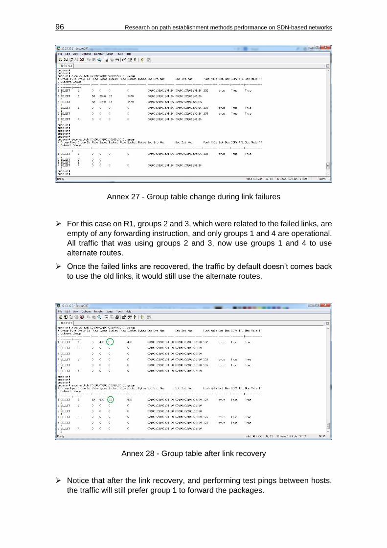
96 Research on path establishment methods performance on SDN-based networks
Annex 27 - Group table change during link failures For this case on R1, groups 2 and 3, which were related to the failed links, are
empty of any forwarding instruction, and only groups 1 and 4 are operational.
All traffic that was using groups 2 and 3, now use groups 1 and 4 to use
alternate routes.
Once the failed links are recovered, the traffic by default doesn’t comes back
to use the old links, it would still use the alternate routes.
Annex 28 - Group table after link recovery Notice that after the link recovery, and performing test pings between hosts,
the traffic will still prefer group 1 to forward the packages.
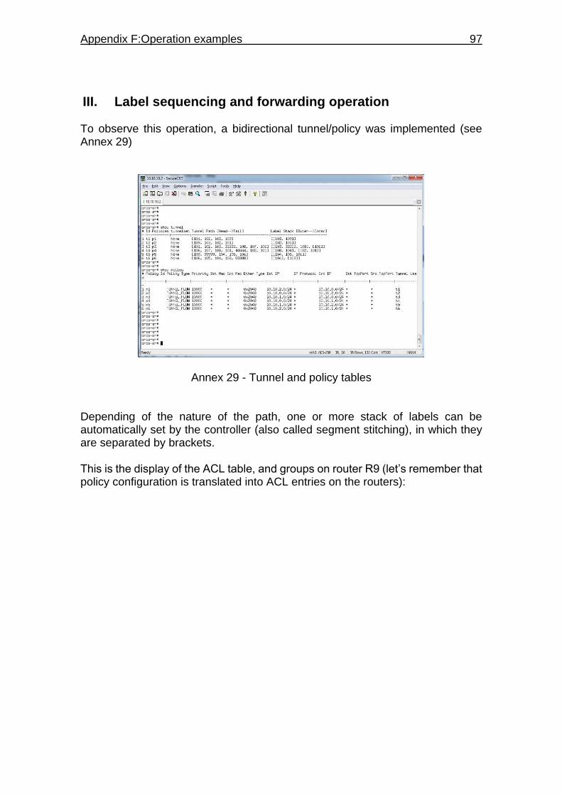
Appendix F:Operation examples 97
III. Label sequencing and forwarding operation To observe this operation, a bidirectional tunnel/policy was implemented (see Annex 29)
Annex 29 - Tunnel and policy tables Depending of the nature of the path, one or more stack of labels can be automatically set by the controller (also called segment stitching), in which they are separated by brackets. This is the display of the ACL table, and groups on router R9 (let’s remember that policy configuration is translated into ACL entries on the routers):

98 Research on path establishment methods performance on SDN-based networks
Annex 30 - Group chaining and forwarding action example Observations Notice that a new entry has been added on the ACL list of the router stating a
call for group 58 on the packages that complies with the policy.
Group 58 pushes the MPLS label 101 and calls for group 57, which pushes
label 102 on the stack for all outbound packages treated by the policy.
Finally, group 58 forwards the packet to output port 4 (the output interface)

Appendix G:Statistic procedure 99
APPENDIX G: STATISTIC PROCEDURE For the measurements exercised on each test, besides maximum, minimum, and average values, there was also the observation of the sample standard deviation, and the confidence interval taken at a 95% of confidence. To obtain these values, the following procedure was followed:
I. Average and standard deviation For n measurements, the average value is calculated with the following equation:
𝑋 =∑ 𝑋𝑖𝑛
1
𝑛 (a)
Where X is the average value, and Xi is a particular sample of the measurement.
The sample standard deviation (σ) is obtained by calculating the variance (σ²)
from the samples measured and the average value:
𝜎2 =∑ (𝑋𝑖−𝑋)2𝑛
1
𝑛−1 (b)
II. Confidence Interval (CI) It is recommendable to calculate the confidence interval, as long the samples tends to approximate a normal distribution behavior. Otherwise, sudden variations in the measurements can put the CI into different ranges, which not necessarily is the tendency of the system. So, in order to verify that the measurements tends to be normally distributed, the samples are compared with the standard normal distribution variables (Z distribution)27. The Z distribution is used to visualize the expected values of the samples distributed along the normal curve. This expected values are compared with the samples (Xi) in a graph called the Quantile-Quantile plot28, where the Z variables are represented on the horizontal axis, and the samples in the vertical axis. If the trend line resulted in the graph approaches to a linear trend, then it is reasonable to consider that the measurements tends to a normal distribution. To determine the Z variables, first it is necessary to determine each of the quantiles for a given number of samples n. These quantiles are determined by the following expression: 27 JBstatistics (2013), Standardizing Normally Distributed Random Variables, retrieved from Youtube: https://www.youtube.com/watch?v=4R8xm19DmPM 28 JBstatistics (2013), Normal Quantile-Quantile Plots, retrieved from Youtube: https://www.youtube.com/watch?v=X9_ISJ0YpGw

100 Research on path establishment methods performance on SDN-based networks
𝑖−0.5
𝑛 (c)
Where i is the ith ordered value of the samples (ordered from smallest to largest). From these quantiles, the Z variables can be determined using either a standard normal table, or through a computer software. In this case, Microsoft Excel offers a function called NORM.S.INV(), which gives the inverse of the normal standard cumulative distribution (Z variables). Once it is confirmed that the samples tends to be normally distributed, the Confidence Interval is calculated. The CI in this case, is used to determine how
close the average value X is to the mean µ from a given number of samples. In
order to do this, a margin of error is determined and the CI is expressed by:
𝐶𝐼 = 𝑋 ± 𝑀𝑎𝑟𝑔𝑖𝑛 𝑜𝑓 𝐸𝑟𝑟𝑜𝑟 29 (d)
This expressions is the most used with samples that are normally distributed. Mathematical arguments are used to determine the appropriate margin of error, in which the following expression is used when the standard deviation is not known30,
𝑀𝑎𝑟𝑔𝑖𝑛 𝑜𝑓 𝐸𝑟𝑟𝑜𝑟 = 𝑡𝛼2⁄ 𝑥
𝜎
√𝑛 (e)
where 𝑡𝛼
2⁄ , is the t distribution with n-1 degrees of freedom31. It is said that the
standard deviation is not known, because the standard deviation obtained is an estimated value from the samples (sample standard deviation), in which the
expression 𝜎
√𝑛 is sometimes referred as the standard error of the average (SE(X)).
The confidence level of 95% is set by the expression:
(1 − 𝛼)𝑥100% (f)
29 JBstatistics (2013), Introduction to Confidence Intervals, retrieved from Youtube: https://www.youtube.com/watch?v=27iSnzss2wM
30 JBstatistics (2013), Confidence Intervals for One Mean: Sigma Not Known (t Method), retrieved from Youtube: https://www.youtube.com/watch?v=bFefxSE5bmo
31 JBstatistics (2013), Introduction to the t Distribution (non-technical), retrieved from Youtube: https://www.youtube.com/watch?v=Uv6nGIgZMVw

Appendix G:Statistic procedure 101
In which α, is the area left out of the confidence level within the t distribution, and it is set to 0.05 for a confidence level of 95%. The t distribution is then obtained through a t table or software. In this case, Microsoft Excel offers the function TINV(α,DF), which determines the t variables according to the probability α and the degrees of freedom DF. Finally, the error margin is obtained, and hence the Confidence Interval by this final expression:
𝐶𝐼 = 𝑋 ± 𝑡𝛼2⁄ 𝑥
𝜎
√𝑛 (g)

102 Research on path establishment methods performance on SDN-based networks
APPENDIX H: MEASUREMENT TABLES
I. Steady state conditions Annex Table 1 – Segment Routing Jitter measurements
Segment Routing
Samples (i) Jitter (ms) Jitter Xi (μs) Sample mean X (µs) (Xi-X)² P((i-0.5)/n) Z Distrb
1 0.02 20 55.95 1292.4025 0.005 -2.576
2 0.026 26 55.95 897.0025 0.015 -2.170
3 0.028 28 55.95 781.2025 0.025 -1.960
4 0.028 28 55.95 781.2025 0.035 -1.812
5 0.03 30 55.95 673.4025 0.045 -1.695
6 0.03 30 55.95 673.4025 0.055 -1.598
7 0.031 31 55.95 622.5025 0.065 -1.514
8 0.031 31 55.95 622.5025 0.075 -1.440
9 0.031 31 55.95 622.5025 0.085 -1.372
10 0.032 32 55.95 573.6025 0.095 -1.311
11 0.032 32 55.95 573.6025 0.105 -1.254
12 0.033 33 55.95 526.7025 0.115 -1.200
13 0.033 33 55.95 526.7025 0.125 -1.150
14 0.035 35 55.95 438.9025 0.135 -1.103
15 0.035 35 55.95 438.9025 0.145 -1.058
16 0.035 35 55.95 438.9025 0.155 -1.015
17 0.035 35 55.95 438.9025 0.165 -0.974
18 0.036 36 55.95 398.0025 0.175 -0.935
19 0.036 36 55.95 398.0025 0.185 -0.896
20 0.036 36 55.95 398.0025 0.195 -0.860
21 0.037 37 55.95 359.1025 0.205 -0.824
22 0.037 37 55.95 359.1025 0.215 -0.789
23 0.037 37 55.95 359.1025 0.225 -0.755
24 0.039 39 55.95 287.3025 0.235 -0.722
25 0.039 39 55.95 287.3025 0.245 -0.690
26 0.04 40 55.95 254.4025 0.255 -0.659
27 0.04 40 55.95 254.4025 0.265 -0.628
28 0.041 41 55.95 223.5025 0.275 -0.598
29 0.041 41 55.95 223.5025 0.285 -0.568
30 0.044 44 55.95 142.8025 0.295 -0.539
31 0.044 44 55.95 142.8025 0.305 -0.510
32 0.045 45 55.95 119.9025 0.315 -0.482
33 0.045 45 55.95 119.9025 0.325 -0.454
34 0.045 45 55.95 119.9025 0.335 -0.426
35 0.045 45 55.95 119.9025 0.345 -0.399

Appendix H:Measurements tables 103
36 0.045 45 55.95 119.9025 0.355 -0.372
37 0.047 47 55.95 80.1025 0.365 -0.345
38 0.047 47 55.95 80.1025 0.375 -0.319
39 0.047 47 55.95 80.1025 0.385 -0.292
40 0.047 47 55.95 80.1025 0.395 -0.266
41 0.047 47 55.95 80.1025 0.405 -0.240
42 0.048 48 55.95 63.2025 0.415 -0.215
43 0.048 48 55.95 63.2025 0.425 -0.189
44 0.049 49 55.95 48.3025 0.435 -0.164
45 0.05 50 55.95 35.4025 0.445 -0.138
46 0.05 50 55.95 35.4025 0.455 -0.113
47 0.051 51 55.95 24.5025 0.465 -0.088
48 0.052 52 55.95 15.6025 0.475 -0.063
49 0.052 52 55.95 15.6025 0.485 -0.038
50 0.052 52 55.95 15.6025 0.495 -0.013
51 0.053 53 55.95 8.7025 0.505 0.013
52 0.054 54 55.95 3.8025 0.515 0.038
53 0.054 54 55.95 3.8025 0.525 0.063
54 0.055 55 55.95 0.9025 0.535 0.088
55 0.055 55 55.95 0.9025 0.545 0.113
56 0.056 56 55.95 0.0025 0.555 0.138
57 0.056 56 55.95 0.0025 0.565 0.164
58 0.057 57 55.95 1.1025 0.575 0.189
59 0.057 57 55.95 1.1025 0.585 0.215
60 0.058 58 55.95 4.2025 0.595 0.240
61 0.059 59 55.95 9.3025 0.605 0.266
62 0.059 59 55.95 9.3025 0.615 0.292
63 0.06 60 55.95 16.4025 0.625 0.319
64 0.061 61 55.95 25.5025 0.635 0.345
65 0.062 62 55.95 36.6025 0.645 0.372
66 0.063 63 55.95 49.7025 0.655 0.399
67 0.063 63 55.95 49.7025 0.665 0.426
68 0.064 64 55.95 64.8025 0.675 0.454
69 0.064 64 55.95 64.8025 0.685 0.482
70 0.065 65 55.95 81.9025 0.695 0.510
71 0.065 65 55.95 81.9025 0.705 0.539
72 0.066 66 55.95 101.0025 0.715 0.568
73 0.066 66 55.95 101.0025 0.725 0.598
74 0.066 66 55.95 101.0025 0.735 0.628
75 0.068 68 55.95 145.2025 0.745 0.659
76 0.072 72 55.95 257.6025 0.755 0.690
77 0.072 72 55.95 257.6025 0.765 0.722
78 0.073 73 55.95 290.7025 0.775 0.755
79 0.074 74 55.95 325.8025 0.785 0.789
80 0.075 75 55.95 362.9025 0.795 0.824
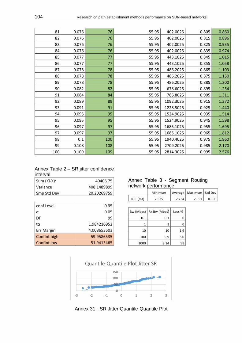
104 Research on path establishment methods performance on SDN-based networks
81 0.076 76 55.95 402.0025 0.805 0.860
82 0.076 76 55.95 402.0025 0.815 0.896
83 0.076 76 55.95 402.0025 0.825 0.935
84 0.076 76 55.95 402.0025 0.835 0.974
85 0.077 77 55.95 443.1025 0.845 1.015
86 0.077 77 55.95 443.1025 0.855 1.058
87 0.078 78 55.95 486.2025 0.865 1.103
88 0.078 78 55.95 486.2025 0.875 1.150
89 0.078 78 55.95 486.2025 0.885 1.200
90 0.082 82 55.95 678.6025 0.895 1.254
91 0.084 84 55.95 786.8025 0.905 1.311
92 0.089 89 55.95 1092.3025 0.915 1.372
93 0.091 91 55.95 1228.5025 0.925 1.440
94 0.095 95 55.95 1524.9025 0.935 1.514
95 0.095 95 55.95 1524.9025 0.945 1.598
96 0.097 97 55.95 1685.1025 0.955 1.695
97 0.097 97 55.95 1685.1025 0.965 1.812
98 0.1 100 55.95 1940.4025 0.975 1.960
99 0.108 108 55.95 2709.2025 0.985 2.170
100 0.109 109 55.95 2814.3025 0.995 2.576
Annex Table 2 – SR jitter confidence interval
Sum (Xi-X)² 40406.75
Variance 408.1489899
Smp Std Dev 20.20269759
conf Level 0.95
α 0.05
DF 99
tα 1.984216952
Err Margin 4.008653503
ConfInt high 59.9586535
ConfInt low 51.9413465
Annex Table 3 - Segment Routing network performance
Minimum Average Maximum Std Dev
RTT (ms) 2.535 2.734 2.951 0.103
Bw (Mbps) Rx Bw (Mbps) Loss %
0.1 0.1 0
1 1 0
10 10 1.6
100 9.9 90
1000 9.24 98
Annex 31 - SR Jitter Quantile-Quantile Plot
0
50
100
150
-3 -2 -1 0 1 2 3
Quantile-Quantile Plot Jitter SR

Appendix H:Measurements tables 105
Annex Table 4 - Proactive Forwarding jitter measurements
Intent Forwarding
Samples (i) Jitter (ms) Jitter Xi (μs) Sample mean X (µs) (Xi-X)² P((i-0.5)/n) Z Distrb
1 0.016 16 43.94 780.6436 0.005 -2.576
2 0.016 16 43.94 780.6436 0.015 -2.170
3 0.017 17 43.94 725.7636 0.025 -1.960
4 0.017 17 43.94 725.7636 0.035 -1.812
5 0.018 18 43.94 672.8836 0.045 -1.695
6 0.019 19 43.94 622.0036 0.055 -1.598
7 0.019 19 43.94 622.0036 0.065 -1.514
8 0.019 19 43.94 622.0036 0.075 -1.440
9 0.019 19 43.94 622.0036 0.085 -1.372
10 0.019 19 43.94 622.0036 0.095 -1.311
11 0.019 19 43.94 622.0036 0.105 -1.254
12 0.02 20 43.94 573.1236 0.115 -1.200
13 0.02 20 43.94 573.1236 0.125 -1.150
14 0.021 21 43.94 526.2436 0.135 -1.103
15 0.021 21 43.94 526.2436 0.145 -1.058
16 0.021 21 43.94 526.2436 0.155 -1.015
17 0.021 21 43.94 526.2436 0.165 -0.974
18 0.021 21 43.94 526.2436 0.175 -0.935
19 0.022 22 43.94 481.3636 0.185 -0.896
20 0.022 22 43.94 481.3636 0.195 -0.860
21 0.022 22 43.94 481.3636 0.205 -0.824
22 0.022 22 43.94 481.3636 0.215 -0.789
23 0.022 22 43.94 481.3636 0.225 -0.755
24 0.023 23 43.94 438.4836 0.235 -0.722
25 0.023 23 43.94 438.4836 0.245 -0.690
26 0.023 23 43.94 438.4836 0.255 -0.659
27 0.023 23 43.94 438.4836 0.265 -0.628
28 0.024 24 43.94 397.6036 0.275 -0.598
29 0.024 24 43.94 397.6036 0.285 -0.568
30 0.024 24 43.94 397.6036 0.295 -0.539
31 0.025 25 43.94 358.7236 0.305 -0.510
32 0.025 25 43.94 358.7236 0.315 -0.482
33 0.026 26 43.94 321.8436 0.325 -0.454
34 0.026 26 43.94 321.8436 0.335 -0.426
35 0.026 26 43.94 321.8436 0.345 -0.399
36 0.027 27 43.94 286.9636 0.355 -0.372
37 0.027 27 43.94 286.9636 0.365 -0.345
38 0.027 27 43.94 286.9636 0.375 -0.319
39 0.027 27 43.94 286.9636 0.385 -0.292
40 0.028 28 43.94 254.0836 0.395 -0.266

106 Research on path establishment methods performance on SDN-based networks
41 0.028 28 43.94 254.0836 0.405 -0.240
42 0.028 28 43.94 254.0836 0.415 -0.215
43 0.029 29 43.94 223.2036 0.425 -0.189
44 0.029 29 43.94 223.2036 0.435 -0.164
45 0.029 29 43.94 223.2036 0.445 -0.138
46 0.029 29 43.94 223.2036 0.455 -0.113
47 0.029 29 43.94 223.2036 0.465 -0.088
48 0.03 30 43.94 194.3236 0.475 -0.063
49 0.031 31 43.94 167.4436 0.485 -0.038
50 0.032 32 43.94 142.5636 0.495 -0.013
51 0.032 32 43.94 142.5636 0.505 0.013
52 0.032 32 43.94 142.5636 0.515 0.038
53 0.033 33 43.94 119.6836 0.525 0.063
54 0.033 33 43.94 119.6836 0.535 0.088
55 0.034 34 43.94 98.8036 0.545 0.113
56 0.034 34 43.94 98.8036 0.555 0.138
57 0.034 34 43.94 98.8036 0.565 0.164
58 0.034 34 43.94 98.8036 0.575 0.189
59 0.035 35 43.94 79.9236 0.585 0.215
60 0.036 36 43.94 63.0436 0.595 0.240
61 0.036 36 43.94 63.0436 0.605 0.266
62 0.036 36 43.94 63.0436 0.615 0.292
63 0.036 36 43.94 63.0436 0.625 0.319
64 0.037 37 43.94 48.1636 0.635 0.345
65 0.038 38 43.94 35.2836 0.645 0.372
66 0.038 38 43.94 35.2836 0.655 0.399
67 0.038 38 43.94 35.2836 0.665 0.426
68 0.039 39 43.94 24.4036 0.675 0.454
69 0.04 40 43.94 15.5236 0.685 0.482
70 0.041 41 43.94 8.6436 0.695 0.510
71 0.041 41 43.94 8.6436 0.705 0.539
72 0.041 41 43.94 8.6436 0.715 0.568
73 0.041 41 43.94 8.6436 0.725 0.598
74 0.046 46 43.94 4.2436 0.735 0.628
75 0.047 47 43.94 9.3636 0.745 0.659
76 0.047 47 43.94 9.3636 0.755 0.690
77 0.047 47 43.94 9.3636 0.765 0.722
78 0.047 47 43.94 9.3636 0.775 0.755
79 0.047 47 43.94 9.3636 0.785 0.789
80 0.047 47 43.94 9.3636 0.795 0.824
81 0.051 51 43.94 49.8436 0.805 0.860
82 0.056 56 43.94 145.4436 0.815 0.896
83 0.057 57 43.94 170.5636 0.825 0.935
84 0.07 70 43.94 679.1236 0.835 0.974
85 0.072 72 43.94 787.3636 0.845 1.015

Appendix H:Measurements tables 107
86 0.073 73 43.94 844.4836 0.855 1.058
87 0.073 73 43.94 844.4836 0.865 1.103
88 0.075 75 43.94 964.7236 0.875 1.150
89 0.077 77 43.94 1092.9636 0.885 1.200
90 0.079 79 43.94 1229.2036 0.895 1.254
91 0.08 80 43.94 1300.3236 0.905 1.311
92 0.08 80 43.94 1300.3236 0.915 1.372
93 0.085 85 43.94 1685.9236 0.925 1.440
94 0.093 93 43.94 2406.8836 0.935 1.514
95 0.103 103 43.94 3488.0836 0.945 1.598
96 0.117 117 43.94 5337.7636 0.955 1.695
97 0.151 151 43.94 11461.8436 0.965 1.812
98 0.16 160 43.94 13469.9236 0.975 1.960
99 0.232 232 43.94 35366.5636 0.985 2.170
100 0.268 268 43.94 50202.8836 0.995 2.576
Annex Table 5 - PF jitter confidence interval
Sum (Xi-X)² 156131.64
Variance 1577.087273
Smp Std Dev 39.71255812
conf Level 0.95
α 0.05
DF 99
tα 1.984216952
Err Margin 7.879833102
ConfInt high 51.8198331
ConfInt low 36.0601669
Annex Table 6 - Proactive Forwarding network performance
Minimum Average Maximum Std Dev
RTT (ms) 1.384 1.548 1.839 0.091
Bw (Mbps) Rx Bw (Mbps) Loss %
0.1 0.1 0
1 0.412 0
10 2.24 0
100 3.31 78
1000 2.89 96
Annex 32 - PF Jitter Quantile-Quantile Plot
-100
0
100
200
300
-3 -2 -1 0 1 2 3
Quantile-Quantile Plot Jitter PF
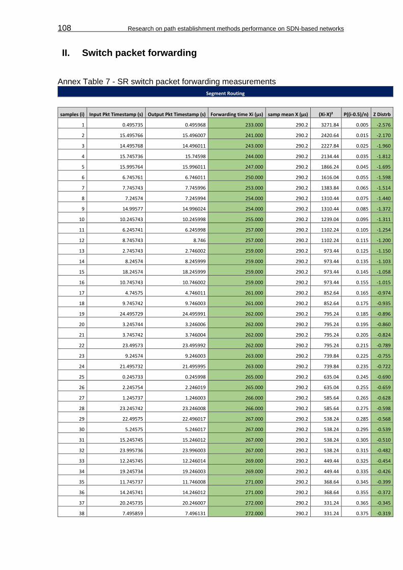
108 Research on path establishment methods performance on SDN-based networks
II. Switch packet forwarding Annex Table 7 - SR switch packet forwarding measurements
Segment Routing
samples (i) Input Pkt Timestamp (s) Output Pkt Timestamp (s) Forwarding time Xi (μs) samp mean X (μs) (Xi-X)² P((i-0.5)/n) Z Distrb
1 0.495735 0.495968 233.000 290.2 3271.84 0.005 -2.576
2 15.495766 15.496007 241.000 290.2 2420.64 0.015 -2.170
3 14.495768 14.496011 243.000 290.2 2227.84 0.025 -1.960
4 15.745736 15.74598 244.000 290.2 2134.44 0.035 -1.812
5 15.995764 15.996011 247.000 290.2 1866.24 0.045 -1.695
6 6.745761 6.746011 250.000 290.2 1616.04 0.055 -1.598
7 7.745743 7.745996 253.000 290.2 1383.84 0.065 -1.514
8 7.24574 7.245994 254.000 290.2 1310.44 0.075 -1.440
9 14.99577 14.996024 254.000 290.2 1310.44 0.085 -1.372
10 10.245743 10.245998 255.000 290.2 1239.04 0.095 -1.311
11 6.245741 6.245998 257.000 290.2 1102.24 0.105 -1.254
12 8.745743 8.746 257.000 290.2 1102.24 0.115 -1.200
13 2.745743 2.746002 259.000 290.2 973.44 0.125 -1.150
14 8.24574 8.245999 259.000 290.2 973.44 0.135 -1.103
15 18.24574 18.245999 259.000 290.2 973.44 0.145 -1.058
16 10.745743 10.746002 259.000 290.2 973.44 0.155 -1.015
17 4.74575 4.746011 261.000 290.2 852.64 0.165 -0.974
18 9.745742 9.746003 261.000 290.2 852.64 0.175 -0.935
19 24.495729 24.495991 262.000 290.2 795.24 0.185 -0.896
20 3.245744 3.246006 262.000 290.2 795.24 0.195 -0.860
21 3.745742 3.746004 262.000 290.2 795.24 0.205 -0.824
22 23.49573 23.495992 262.000 290.2 795.24 0.215 -0.789
23 9.24574 9.246003 263.000 290.2 739.84 0.225 -0.755
24 21.495732 21.495995 263.000 290.2 739.84 0.235 -0.722
25 0.245733 0.245998 265.000 290.2 635.04 0.245 -0.690
26 2.245754 2.246019 265.000 290.2 635.04 0.255 -0.659
27 1.245737 1.246003 266.000 290.2 585.64 0.265 -0.628
28 23.245742 23.246008 266.000 290.2 585.64 0.275 -0.598
29 22.49575 22.496017 267.000 290.2 538.24 0.285 -0.568
30 5.24575 5.246017 267.000 290.2 538.24 0.295 -0.539
31 15.245745 15.246012 267.000 290.2 538.24 0.305 -0.510
32 23.995736 23.996003 267.000 290.2 538.24 0.315 -0.482
33 12.245745 12.246014 269.000 290.2 449.44 0.325 -0.454
34 19.245734 19.246003 269.000 290.2 449.44 0.335 -0.426
35 11.745737 11.746008 271.000 290.2 368.64 0.345 -0.399
36 14.245741 14.246012 271.000 290.2 368.64 0.355 -0.372
37 20.245735 20.246007 272.000 290.2 331.24 0.365 -0.345
38 7.495859 7.496131 272.000 290.2 331.24 0.375 -0.319

Appendix H:Measurements tables 109
39 17.745734 17.746006 272.000 290.2 331.24 0.385 -0.292
40 21.99573 21.996002 272.000 290.2 331.24 0.395 -0.266
41 13.245747 13.24602 273.000 290.2 295.84 0.405 -0.240
42 20.495727 20.496 273.000 290.2 295.84 0.415 -0.215
43 6.495854 6.496127 273.000 290.2 295.84 0.425 -0.189
44 16.745761 16.746035 274.000 290.2 262.44 0.435 -0.164
45 17.245739 17.246013 274.000 290.2 262.44 0.445 -0.138
46 14.745744 14.746019 275.000 290.2 231.04 0.455 -0.113
47 11.245748 11.246025 277.000 290.2 174.24 0.465 -0.088
48 13.745741 13.746018 277.000 290.2 174.24 0.475 -0.063
49 12.745747 12.746024 277.000 290.2 174.24 0.485 -0.038
50 20.745751 20.746028 277.000 290.2 174.24 0.495 -0.013
51 20.995736 20.996013 277.000 290.2 174.24 0.505 0.013
52 21.745731 21.746008 277.000 290.2 174.24 0.515 0.038
53 22.745732 22.746009 277.000 290.2 174.24 0.525 0.063
54 4.245779 4.246057 278.000 290.2 148.84 0.535 0.088
55 18.495816 18.496095 279.000 290.2 125.44 0.545 0.113
56 6.995858 6.996138 280.000 290.2 104.04 0.555 0.138
57 17.49582 17.4961 280.000 290.2 104.04 0.565 0.164
58 19.745737 19.746017 280.000 290.2 104.04 0.575 0.189
59 16.245736 16.246017 281.000 290.2 84.64 0.585 0.215
60 1.74575 1.746031 281.000 290.2 84.64 0.595 0.240
61 5.74574 5.746023 283.000 290.2 51.84 0.605 0.266
62 16.995825 16.996115 290.000 290.2 0.04 0.615 0.292
63 17.995822 17.996114 292.000 290.2 3.23999999 0.625 0.319
64 19.995816 19.996108 292.000 290.2 3.23999999 0.635 0.345
65 21.245737 21.246029 292.000 290.2 3.24000001 0.645 0.372
66 19.495812 19.496106 294.000 290.2 14.44 0.655 0.399
67 0.745829 0.746124 295.000 290.2 23.04 0.665 0.426
68 22.245638 22.245938 300.000 290.2 96.04 0.675 0.454
69 9.495885 9.496185 300.000 290.2 96.04 0.685 0.482
70 5.995868 5.99617 302.000 290.2 139.24 0.695 0.510
71 1.495842 1.496151 309.000 290.2 353.44 0.705 0.539
72 4.995835 4.996147 312.000 290.2 475.24 0.715 0.568
73 5.495855 5.496168 313.000 290.2 519.84 0.725 0.598
74 12.495825 12.496139 314.000 290.2 566.44 0.735 0.628
75 2.995861 2.996175 314.000 290.2 566.44 0.745 0.659
76 1.995851 1.996166 315.000 290.2 615.04 0.755 0.690
77 2.495847 2.496162 315.000 290.2 615.04 0.765 0.722
78 13.495826 13.496141 315.000 290.2 615.04 0.775 0.755
79 13.995824 13.99614 316.000 290.2 665.64 0.785 0.789
80 10.996865 10.997182 317.000 290.2 718.24 0.795 0.824
81 9.995879 9.996197 318.000 290.2 772.84 0.805 0.860
82 12.995837 12.996155 318.000 290.2 772.84 0.815 0.896
83 0.995848 0.996167 319.000 290.2 829.44 0.825 0.935
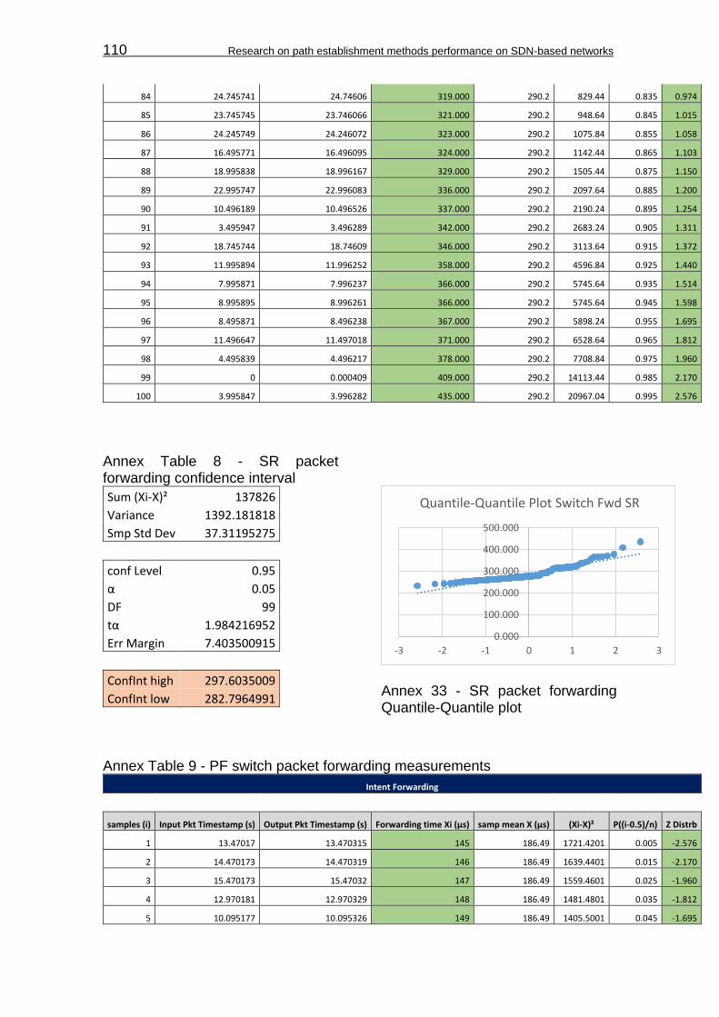
110 Research on path establishment methods performance on SDN-based networks
84 24.745741 24.74606 319.000 290.2 829.44 0.835 0.974
85 23.745745 23.746066 321.000 290.2 948.64 0.845 1.015
86 24.245749 24.246072 323.000 290.2 1075.84 0.855 1.058
87 16.495771 16.496095 324.000 290.2 1142.44 0.865 1.103
88 18.995838 18.996167 329.000 290.2 1505.44 0.875 1.150
89 22.995747 22.996083 336.000 290.2 2097.64 0.885 1.200
90 10.496189 10.496526 337.000 290.2 2190.24 0.895 1.254
91 3.495947 3.496289 342.000 290.2 2683.24 0.905 1.311
92 18.745744 18.74609 346.000 290.2 3113.64 0.915 1.372
93 11.995894 11.996252 358.000 290.2 4596.84 0.925 1.440
94 7.995871 7.996237 366.000 290.2 5745.64 0.935 1.514
95 8.995895 8.996261 366.000 290.2 5745.64 0.945 1.598
96 8.495871 8.496238 367.000 290.2 5898.24 0.955 1.695
97 11.496647 11.497018 371.000 290.2 6528.64 0.965 1.812
98 4.495839 4.496217 378.000 290.2 7708.84 0.975 1.960
99 0 0.000409 409.000 290.2 14113.44 0.985 2.170
100 3.995847 3.996282 435.000 290.2 20967.04 0.995 2.576
Annex Table 8 - SR packet forwarding confidence interval
Sum (Xi-X)² 137826
Variance 1392.181818
Smp Std Dev 37.31195275
conf Level 0.95
α 0.05
DF 99
tα 1.984216952
Err Margin 7.403500915
ConfInt high 297.6035009
ConfInt low 282.7964991
Annex 33 - SR packet forwarding Quantile-Quantile plot
Annex Table 9 - PF switch packet forwarding measurements
Intent Forwarding
samples (i) Input Pkt Timestamp (s) Output Pkt Timestamp (s) Forwarding time Xi (μs) samp mean X (μs) (Xi-X)² P((i-0.5)/n) Z Distrb
1 13.47017 13.470315 145 186.49 1721.4201 0.005 -2.576
2 14.470173 14.470319 146 186.49 1639.4401 0.015 -2.170
3 15.470173 15.47032 147 186.49 1559.4601 0.025 -1.960
4 12.970181 12.970329 148 186.49 1481.4801 0.035 -1.812
5 10.095177 10.095326 149 186.49 1405.5001 0.045 -1.695
0.000
100.000
200.000
300.000
400.000
500.000
-3 -2 -1 0 1 2 3
Quantile-Quantile Plot Switch Fwd SR

Appendix H:Measurements tables 111
6 12.095179 12.095328 149 186.49 1405.5001 0.055 -1.598
7 12.470182 12.470331 149 186.49 1405.5001 0.065 -1.514
8 13.970177 13.970326 149 186.49 1405.5001 0.075 -1.440
9 14.720176 14.720325 149 186.49 1405.5001 0.085 -1.372
10 16.220174 16.220323 149 186.49 1405.5001 0.095 -1.311
11 9.970179 9.970329 150 186.49 1331.5201 0.105 -1.254
12 11.970181 11.970331 150 186.49 1331.5201 0.115 -1.200
13 6.470183 6.470333 150 186.49 1331.5201 0.125 -1.150
14 11.47018 11.47033 150 186.49 1331.5201 0.135 -1.103
15 16.095163 16.095313 150 186.49 1331.5201 0.145 -1.058
16 11.095178 11.095329 151 186.49 1259.5401 0.155 -1.015
17 12.720176 12.720327 151 186.49 1259.5401 0.165 -0.974
18 10.970181 10.970332 151 186.49 1259.5401 0.175 -0.935
19 13.720177 13.720328 151 186.49 1259.5401 0.185 -0.896
20 14.095181 14.095332 151 186.49 1259.5401 0.195 -0.860
21 15.09518 15.095331 151 186.49 1259.5401 0.205 -0.824
22 15.220175 15.220326 151 186.49 1259.5401 0.215 -0.789
23 8.970184 8.970336 152 186.49 1189.5601 0.225 -0.755
24 10.470178 10.47033 152 186.49 1189.5601 0.235 -0.722
25 13.095182 13.095334 152 186.49 1189.5601 0.245 -0.690
26 14.220179 14.220331 152 186.49 1189.5601 0.255 -0.659
27 15.720176 15.720328 152 186.49 1189.5601 0.265 -0.628
28 9.47018 9.470332 152 186.49 1189.5601 0.275 -0.598
29 13.220188 13.220341 153 186.49 1121.5801 0.285 -0.568
30 14.595185 14.595338 153 186.49 1121.5801 0.295 -0.539
31 7.470181 7.470334 153 186.49 1121.5801 0.305 -0.510
32 12.595185 12.595339 154 186.49 1055.6001 0.315 -0.482
33 7.97019 7.970344 154 186.49 1055.6001 0.325 -0.454
34 12.220184 12.220339 155 186.49 991.6201 0.335 -0.426
35 6.970183 6.970338 155 186.49 991.6201 0.345 -0.399
36 10.595183 10.595339 156 186.49 929.6401 0.355 -0.372
37 13.595183 13.595339 156 186.49 929.6401 0.365 -0.345
38 9.345213 9.34537 157 186.49 869.6601 0.375 -0.319
39 8.470191 8.470349 158 186.49 811.6801 0.385 -0.292
40 9.595186 9.595344 158 186.49 811.6801 0.395 -0.266
41 12.345194 12.345355 161 186.49 649.7401 0.405 -0.240
42 15.595189 15.59535 161 186.49 649.7401 0.415 -0.215
43 11.595218 11.595381 163 186.49 551.7801 0.425 -0.189
44 14.345222 14.345387 165 186.49 461.8201 0.435 -0.164
45 13.34522 13.34539 170 186.49 271.9201 0.445 -0.138
46 6.220206 6.220383 177 186.49 90.0601 0.455 -0.113
47 9.845252 9.845433 181 186.49 30.1401 0.465 -0.088
48 12.845252 12.845433 181 186.49 30.1401 0.475 -0.063
49 11.845258 11.845439 181 186.49 30.1401 0.485 -0.038
50 4.845173 4.845355 182 186.49 20.1601 0.495 -0.013
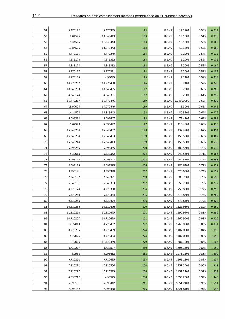
112 Research on path establishment methods performance on SDN-based networks
51 5.470172 5.470355 183 186.49 12.1801 0.505 0.013
52 10.84526 10.845443 183 186.49 12.1801 0.515 0.038
53 11.34526 11.345443 183 186.49 12.1801 0.525 0.063
54 13.84526 13.845443 183 186.49 12.1801 0.535 0.088
55 4.470165 4.470349 184 186.49 6.2001 0.545 0.113
56 5.345178 5.345362 184 186.49 6.2001 0.555 0.138
57 5.845178 5.845362 184 186.49 6.2001 0.565 0.164
58 5.970177 5.970361 184 186.49 6.2001 0.575 0.189
59 4.970165 4.97035 185 186.49 2.2201 0.585 0.215
60 14.970252 14.970438 186 186.49 0.2401 0.595 0.240
61 10.345268 10.345455 187 186.49 0.2601 0.605 0.266
62 4.345174 4.345361 187 186.49 0.2601 0.615 0.292
63 16.470257 16.470446 189 186.49 6.30009999 0.625 0.319
64 15.97026 15.970449 189 186.49 6.3001 0.635 0.345
65 14.84525 14.845442 192 186.49 30.3601 0.645 0.372
66 6.095252 6.095447 195 186.49 72.4201 0.655 0.399
67 5.09528 5.095477 197 186.49 110.4601 0.665 0.426
68 15.845254 15.845452 198 186.49 132.4801 0.675 0.454
69 16.345254 16.345453 199 186.49 156.5001 0.685 0.482
70 15.345244 15.345443 199 186.49 156.5001 0.695 0.510
71 5.595255 5.595455 200 186.49 182.5201 0.705 0.539
72 5.22018 5.220382 202 186.49 240.5601 0.715 0.568
73 9.095175 9.095377 202 186.49 240.5601 0.725 0.598
74 8.095179 8.095385 206 186.49 380.6401 0.735 0.628
75 8.595181 8.595388 207 186.49 420.6601 0.745 0.659
76 7.345182 7.345391 209 186.49 506.7001 0.755 0.690
77 6.845181 6.845393 212 186.49 650.7601 0.765 0.722
78 4.220174 4.220388 214 186.49 756.8001 0.775 0.755
79 5.720269 5.720484 215 186.49 812.8201 0.785 0.789
80 9.220258 9.220474 216 186.49 870.8401 0.795 0.824
81 10.220256 10.220476 220 186.49 1122.9201 0.805 0.860
82 11.220254 11.220475 221 186.49 1190.9401 0.815 0.896
83 10.720257 10.720479 222 186.49 1260.9601 0.825 0.935
84 4.72018 4.720402 222 186.49 1260.9601 0.835 0.974
85 8.220265 8.220489 224 186.49 1407.0001 0.845 1.015
86 8.72026 8.720484 224 186.49 1407.0001 0.855 1.058
87 11.72026 11.720489 229 186.49 1807.1001 0.865 1.103
88 6.720277 6.720507 230 186.49 1893.1201 0.875 1.150
89 4.0952 4.095432 232 186.49 2071.1601 0.885 1.200
90 9.720262 9.720495 233 186.49 2163.1801 0.895 1.254
91 7.220272 7.220506 234 186.49 2257.2001 0.905 1.311
92 7.720277 7.720513 236 186.49 2451.2401 0.915 1.372
93 4.595212 4.59545 238 186.49 2653.2801 0.925 1.440
94 6.595181 6.595442 261 186.49 5551.7401 0.935 1.514
95 7.095182 7.095448 266 186.49 6321.8401 0.945 1.598
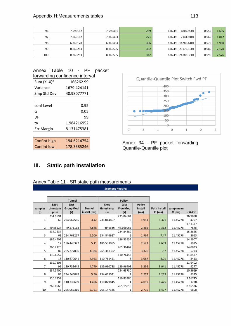
Appendix H:Measurements tables 113
96 7.595182 7.595451 269 186.49 6807.9001 0.955 1.695
97 7.845182 7.845453 271 186.49 7141.9401 0.965 1.812
98 6.345178 6.345484 306 186.49 14282.6401 0.975 1.960
99 8.845253 8.845585 332 186.49 21173.1601 0.985 2.170
100 8.345253 8.345595 342 186.49 24183.3601 0.995 2.576
Annex Table 10 - PF packet forwarding confidence interval
Sum (Xi-X)² 166262.99
Variance 1679.424141
Smp Std Dev 40.98077771
conf Level 0.95
α 0.05
DF 99
tα 1.984216952
Err Margin 8.131475381
ConfInt high 194.6214754
ConfInt low 178.3585246
Annex 34 - PF packet forwarding Quantile-Quantile plot
III. Static path installation Annex Table 11 - SR static path measurements
Segment Routing
Tunnel Policy
samples (i)
Exec timestam
p (s)
Last GroupMod
(s) Tunnel
install (ms)
Exec timestamp
(s)
Last FlowMod
(s)
Policy install (ms)
Path install Xi (ms)
samp mean X (ms) (Xi-X)²
1 234.9591
65 234.962585 3.42 235.044867 235.04681
8 1.951 5.371 11.45278 36.9880
4797
2 49.56627 49.571118 4.848 49.6636 49.666065 2.465 7.313 11.45278 17.1377
7845
3 234.7637
61 234.769267 5.506 234.846927 234.84889
1 1.964 7.47 11.45278 15.8625
3653
4 186.4402
17 186.445327 5.11 186.533055 186.53557
8 2.523 7.633 11.45278 14.5907
1925
5 265.2726
82 265.277006 4.324 265.361302 265.36467
8 3.376 7.7 11.45278 14.0833
5773
6 110.6657
18 110.670641 4.923 110.761451 110.76453
8 3.087 8.01 11.45278 11.8527
3413
7 139.7308
96 139.735645 4.749 139.960788 139.96408 3.292 8.041 11.45278 11.6402
4277
8 234.5400
89 234.546049 5.96 234.635031 234.63730
4 2.273 8.233 11.45278 10.3669
8325
9 110.7352
03 110.739609 4.406 110.829845 110.83386
4 4.019 8.425 11.45278 9.16745
1728
10 265.0565
55 265.062316 5.761 265.147385 265.15010
1 2.716 8.477 11.45278 8.85526
6608
0
50
100
150
200
250
300
350
400
-3 -2 -1 0 1 2 3
Quantile-Quantile Plot Switch Fwd PF
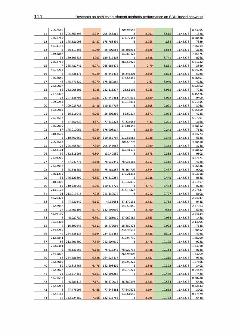
114 Research on path establishment methods performance on SDN-based networks
11 205.8580
82 205.863396 5.314 205.953362 205.95656
3 3.201 8.515 11.45278 8.63055
1328
12 175.6756
11 175.681098 5.487 175.768492 175.77154
5 3.053 8.54 11.45278 8.48428
7329
13 56.31196
2 56.317261 5.299 56.402553 56.405938 3.385 8.684 11.45278 7.66614
2688
14 139.3887
33 139.393636 4.903 139.617403 139.62124
1 3.838 8.741 11.45278 7.35375
0768
15 265.4766
7 265.482741 6.071 265.566472 265.56926
2 2.79 8.861 11.45278 6.71732
3569
16 45.73214
2 45.738171 6.029 45.845438 45.848303 2.865 8.894 11.45278 6.54735
5088
17 175.4650
48 175.471327 6.279 175.560884 175.56355
4 2.67 8.949 11.45278 6.26891
4288
18 282.0007
66 282.005501 4.735 282.115277 282.1195 4.223 8.958 11.45278 6.22392
7248
19 247.3307
13 247.335796 5.083 247.442461 247.44635 3.889 8.972 11.45278 6.15426
9409
20 109.9283
7 109.933786 5.416 110.134708 110.13831
3 3.605 9.021 11.45278 5.91355
3968
21 56.50984
2 56.516045 6.203 56.605299 56.60817 2.871 9.074 11.45278 5.65859
4288
22 77.74536
8 77.750239 4.871 77.832323 77.836653 4.33 9.201 11.45278 5.07051
3168
23 175.9039
67 175.910061 6.094 176.008314 176.01146
3 3.149 9.243 11.45278 4.88312
7648
24 110.4539
5 110.460269 6.319 110.552794 110.55582 3.026 9.345 11.45278 4.44273
6528
25 205.4513
25 205.458684 7.359 205.545968 205.54796
7 1.999 9.358 11.45278 4.38810
3248
26 132.3101
92 132.316996 6.804 132.40859 132.41116
8 2.578 9.382 11.45278 4.28812
9808
27 77.94210
7 77.947775 5.668 78.032449 78.036166 3.717 9.385 11.45278 4.27571
4128
28 75.33996
8 75.346561 6.593 75.461858 75.464702 2.844 9.437 11.45278 4.06336
9008
29 176.1235
35 176.129892 6.357 176.210254 176.21334
2 3.088 9.445 11.45278 4.03118
0528
30 110.2300
62 110.235065 5.003 110.373722 110.37819
3 4.471 9.474 11.45278 3.91557
0288
31 213.0124
01 213.019416 7.015 213.130574 213.13328
6 2.712 9.727 11.45278 2.97831
6608
32 47.22473
2 47.230849 6.117 47.36651 47.370131 3.621 9.738 11.45278 2.94047
0448
33 142.3947
27 142.401198 6.471 142.496999 142.50040
8 3.409 9.88 11.45278 2.47363
6928
34 46.98139
8 46.987789 6.391 47.065919 47.069482 3.563 9.954 11.45278 2.24634
1488
35 16.38403
4 16.390645 6.611 16.479096 16.482478 3.382 9.993 11.45278 2.13095
7648
36 234.3289
44 234.335138 6.194 234.431488 234.43537
4 3.886 10.08 11.45278 1.88452
4928
37 212.7841
58 212.791807 7.649 212.904919 212.90739
5 2.476 10.125 11.45278 1.76299
9728
38 76.82481
9 76.831465 6.646 76.917246 76.920734 3.488 10.134 11.45278 1.73918
0688
39 264.7802
68 264.786896 6.628 264.926476 264.93006
3 3.587 10.215 11.45278 1.53209
9328
40 142.8089
89 142.815465 6.476 142.898409 142.90225
5 3.846 10.322 11.45278 1.27866
3408
41 142.6077
05 142.614256 6.551 142.698284 142.70221
2 3.928 10.479 11.45278 0.94824
7488
42 46.77594
2 46.783113 7.171 46.879015 46.882398 3.383 10.554 11.45278 0.80780
5488
43 77.47252
8 77.478996 6.468 77.645481 77.649675 4.194 10.662 11.45278 0.62533
3008
44 132.5164
14 132.524382 7.968 132.613758 132.61655
3 2.795 10.763 11.45278 0.47579
6448

Appendix H:Measurements tables 115
45 87.52969
2 87.537206 7.514 87.624753 87.628098 3.345 10.859 11.45278 0.35257
4688
46 16.61489
1 16.623639 8.748 16.709557 16.711789 2.232 10.98 11.45278 0.22352
0928
47 49.12932
6 49.135753 6.427 49.239011 49.243577 4.566 10.993 11.45278 0.21139
7648
48 75.75959
2 75.767405 7.813 75.857753 75.861125 3.372 11.185 11.45278 0.07170
6128
49 76.05871 76.066983 8.273 76.171348 76.174382 3.034 11.307 11.45278 0.02125
1808
50 156.0020
48 156.009044 6.996 156.088614 156.09292
8 4.314 11.31 11.45278 0.02038
6128
51 103.7413
94 103.749691 8.297 103.825946 103.82899 3.044 11.341 11.45278 0.01249
4768
52 46.55968
7 46.567802 8.115 46.661902 46.665307 3.405 11.52 11.45278 0.00451
8528
53 205.6504
65 205.658698 8.233 205.755697 205.75908
2 3.385 11.618 11.45278 0.02729
7648
54 103.2951
64 103.303805 8.641 103.412333 103.41545
7 3.124 11.765 11.45278 0.09748
1328
55 186.0331
25 186.040564 7.439 186.127509 186.13184
7 4.338 11.777 11.45278 0.10511
8608
56 110.2450
28 110.253722 8.694 110.343936 110.34722
6 3.29 11.984 11.45278 0.28219
4688
57 142.1741
74 142.182825 8.651 142.275404 142.27880
5 3.401 12.052 11.45278 0.35906
4608
58 205.2264
29 205.235549 9.12 205.343591 205.34659
2 3.001 12.121 11.45278 0.44651
7968
59 186.2287
88 186.236507 7.719 186.325522 186.32999
3 4.471 12.19 11.45278 0.54349
3328
60 213.4796
98 213.487762 8.064 213.597861 213.60200
8 4.147 12.211 11.45278 0.57489
7568
61 76.62898
4 76.636754 7.77 76.722337 76.726864 4.527 12.297 11.45278 0.71270
7408
62 282.2144
42 282.222738 8.296 282.360658 282.36483
4 4.176 12.472 11.45278 1.03880
9408
63 126.9568
4 126.966651 9.811 127.059438 127.06210
3 2.665 12.476 11.45278 1.04697
9168
64 75.04962
9 75.056993 7.364 75.164312 75.169545 5.233 12.597 11.45278 1.30923
9408
65 246.6624
57 246.671415 8.958 246.777554 246.78119
7 3.643 12.601 11.45278 1.31840
9168
66 16.80617
1 16.815522 9.351 16.897521 16.900772 3.251 12.602 11.45278 1.32070
6608
67 246.8930
17 246.901966 8.949 246.982223 246.98596 3.737 12.686 11.45278 1.52083
1568
68 76.28317
2 76.292359 9.187 76.47232 76.475913 3.593 12.78 11.45278 1.76151
2928
69 139.0108
2 139.019688 8.868 139.247526 139.25143
9 3.913 12.781 11.45278 1.76416
8368
70 247.0999
83 247.10899 9.007 247.212784 247.21662
9 3.845 12.852 11.45278 1.95781
6608
71 16.16919
7 16.178052 8.855 16.274508 16.278616 4.108 12.963 11.45278 2.28076
4448
72 213.2497
7 213.258804 9.034 213.37328 213.37722 3.94 12.974 11.45278 2.31411
0288
73 103.9444
11 103.953462 9.051 104.040612 104.04459
9 3.987 13.038 11.45278 2.51292
2448
74 110.4908
43 110.500019 9.176 110.591392 110.59530
6 3.914 13.09 11.45278 2.68048
9328
75 13.97093
7 13.981191 10.254 14.081283 14.084497 3.214 13.468 11.45278 4.06111
1648
76 282.4901
34 282.498726 8.592 282.609048 282.61395
3 4.905 13.497 11.45278 4.17883
5408
77 18.74674
2 18.756389 9.647 18.837486 18.841357 3.871 13.518 11.45278 4.26513
3648
78 126.7368
46 126.747473 10.627 126.838595 126.84153
3 2.938 13.565 11.45278 4.46147
3328
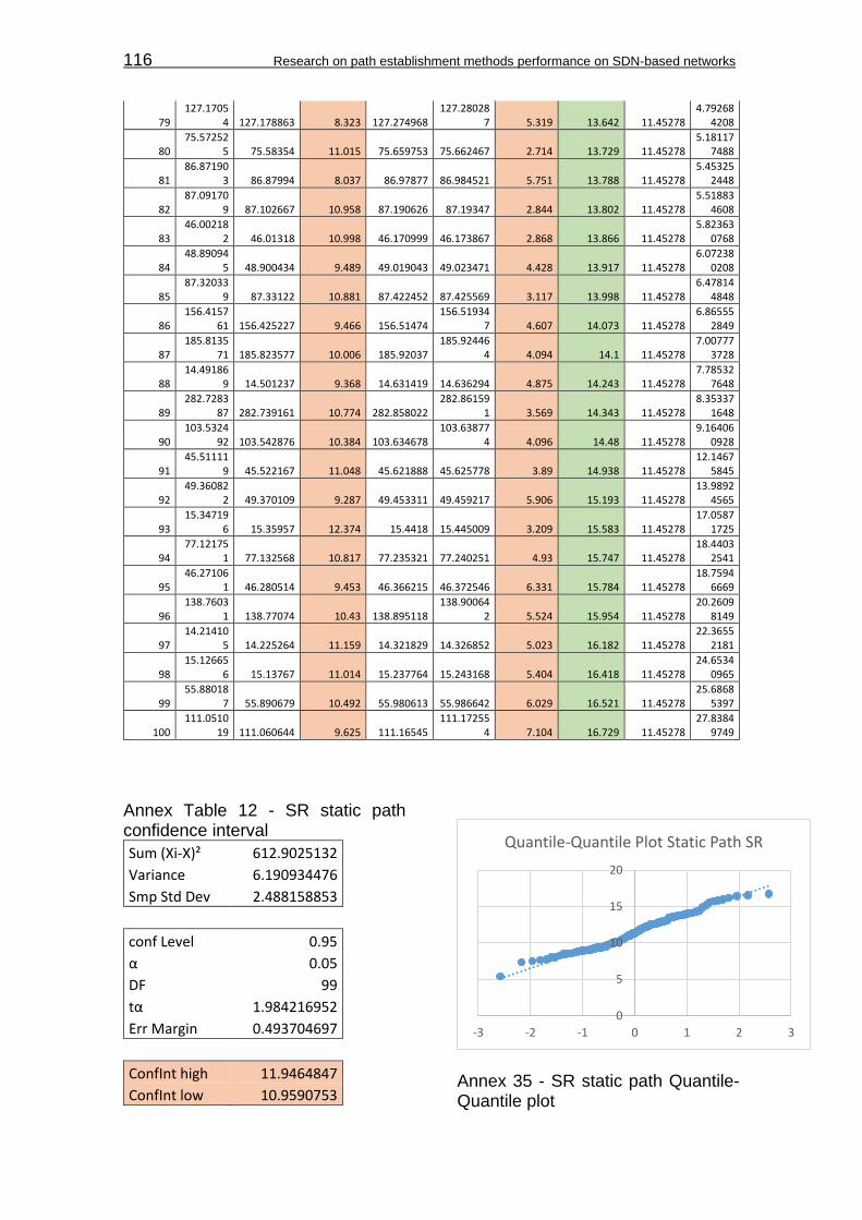
116 Research on path establishment methods performance on SDN-based networks
79 127.1705
4 127.178863 8.323 127.274968 127.28028
7 5.319 13.642 11.45278 4.79268
4208
80 75.57252
5 75.58354 11.015 75.659753 75.662467 2.714 13.729 11.45278 5.18117
7488
81 86.87190
3 86.87994 8.037 86.97877 86.984521 5.751 13.788 11.45278 5.45325
2448
82 87.09170
9 87.102667 10.958 87.190626 87.19347 2.844 13.802 11.45278 5.51883
4608
83 46.00218
2 46.01318 10.998 46.170999 46.173867 2.868 13.866 11.45278 5.82363
0768
84 48.89094
5 48.900434 9.489 49.019043 49.023471 4.428 13.917 11.45278 6.07238
0208
85 87.32033
9 87.33122 10.881 87.422452 87.425569 3.117 13.998 11.45278 6.47814
4848
86 156.4157
61 156.425227 9.466 156.51474 156.51934
7 4.607 14.073 11.45278 6.86555
2849
87 185.8135
71 185.823577 10.006 185.92037 185.92446
4 4.094 14.1 11.45278 7.00777
3728
88 14.49186
9 14.501237 9.368 14.631419 14.636294 4.875 14.243 11.45278 7.78532
7648
89 282.7283
87 282.739161 10.774 282.858022 282.86159
1 3.569 14.343 11.45278 8.35337
1648
90 103.5324
92 103.542876 10.384 103.634678 103.63877
4 4.096 14.48 11.45278 9.16406
0928
91 45.51111
9 45.522167 11.048 45.621888 45.625778 3.89 14.938 11.45278 12.1467
5845
92 49.36082
2 49.370109 9.287 49.453311 49.459217 5.906 15.193 11.45278 13.9892
4565
93 15.34719
6 15.35957 12.374 15.4418 15.445009 3.209 15.583 11.45278 17.0587
1725
94 77.12175
1 77.132568 10.817 77.235321 77.240251 4.93 15.747 11.45278 18.4403
2541
95 46.27106
1 46.280514 9.453 46.366215 46.372546 6.331 15.784 11.45278 18.7594
6669
96 138.7603
1 138.77074 10.43 138.895118 138.90064
2 5.524 15.954 11.45278 20.2609
8149
97 14.21410
5 14.225264 11.159 14.321829 14.326852 5.023 16.182 11.45278 22.3655
2181
98 15.12665
6 15.13767 11.014 15.237764 15.243168 5.404 16.418 11.45278 24.6534
0965
99 55.88018
7 55.890679 10.492 55.980613 55.986642 6.029 16.521 11.45278 25.6868
5397
100 111.0510
19 111.060644 9.625 111.16545 111.17255
4 7.104 16.729 11.45278 27.8384
9749
Annex Table 12 - SR static path confidence interval
Sum (Xi-X)² 612.9025132
Variance 6.190934476
Smp Std Dev 2.488158853
conf Level 0.95
α 0.05
DF 99
tα 1.984216952
Err Margin 0.493704697
ConfInt high 11.9464847
ConfInt low 10.9590753
Annex 35 - SR static path Quantile-Quantile plot
0
5
10
15
20
-3 -2 -1 0 1 2 3
Quantile-Quantile Plot Static Path SR

Appendix H:Measurements tables 117
Annex Table 13 - PF static path measurements
Intent Forwarding
Samples (i) Exec timestamp (s) 1st FlowMod (s) Proc time (ms) Last FlowMod (s) Path install Xi (ms) samp mean X (ms) (Xi-X)²
1 24.148332 24.163759 15.427 24.175457 27.125 52.29085 633.3200062
2 21.843188 21.861017 17.829 21.871478 28.29 52.29085 576.0408007
3 14.572622 14.589202 16.58 14.601089 28.467 52.29085 567.5758288
4 25.642074 25.659869 17.795 25.670946 28.872 52.29085 548.4425353
5 31.31051 31.329418 18.908 31.340736 30.226 52.29085 486.8576055
6 48.023155 48.053729 30.574 48.053942 30.787 52.29085 462.4155648
7 28.150048 28.170378 20.33 28.181348 31.3 52.29085 440.6157837
8 49.441095 49.46061 19.515 49.473489 32.394 52.29085 395.8846399
9 4.459075 4.479099 20.024 4.49147 32.395 52.29085 395.8448472
10 42.778728 42.799222 20.494 42.811529 32.801 52.29085 379.854253
11 34.503008 34.523884 20.876 34.535939 32.931 52.29085 374.803792
12 10.109707 10.131365 21.658 10.143578 33.871 52.29085 339.290874
13 8.863993 8.887068 23.075 8.899461 35.468 52.29085 283.0082821
14 41.410991 41.435602 24.611 41.447319 36.328 52.29085 254.8125801
15 11.726545 11.753689 27.144 11.763427 36.882 52.29085 237.4326583
16 29.00057 29.025426 24.856 29.037611 37.041 52.29085 232.557925
17 12.261572 12.286487 24.915 12.29917 37.598 52.29085 215.8798411
18 40.520457 40.54559 25.133 40.558113 37.656 52.29085 214.1788345
19 9.45717 9.481951 24.781 9.495581 38.411 52.29085 192.650236
20 46.268747 46.294899 26.152 46.307499 38.752 52.29085 183.3004593
21 48.74245 48.769086 26.636 48.781863 39.413 52.29085 165.8390206
22 46.022767 46.051438 28.671 46.062605 39.838 52.29085 155.0734731
23 47.279705 47.307633 27.928 47.319921 40.216 52.29085 145.8020025
24 43.719792 43.747842 28.05 43.760192 40.4 52.29085 141.3923137
25 10.91182 10.939656 27.836 10.952426 40.606 52.29085 136.5357195
26 32.394519 32.42244 27.921 32.435138 40.619 52.29085 136.2320824
27 45.917917 45.946304 28.387 45.958576 40.659 52.29085 135.2999344
28 18.829373 18.858428 29.055 18.870436 41.063 52.29085 126.0646156
29 50.174375 50.203697 29.322 50.215818 41.443 52.29085 117.6758496
30 33.661911 33.690911 29 33.703983 42.072 52.29085 104.4248953
31 45.023439 45.053948 30.509 45.066261 42.822 52.29085 89.65912032
32 21.120018 21.151065 31.047 21.163337 43.319 52.29085 80.49409242
33 33.601103 33.633669 32.566 33.644688 43.585 52.29085 75.79182422
34 26.191221 26.221973 30.752 26.23488 43.659 52.29085 74.50883442
35 14.269304 14.301065 31.761 14.313265 43.961 52.29085 69.38640102
36 30.242004 30.273794 31.79 30.286096 44.092 52.29085 67.22114132
37 43.859681 43.892612 32.931 43.904317 44.636 52.29085 58.59672852
38 36.952977 36.985497 32.52 36.997707 44.73 52.29085 57.16645272
39 5.087257 5.121704 34.447 5.133389 46.132 52.29085 37.93143332
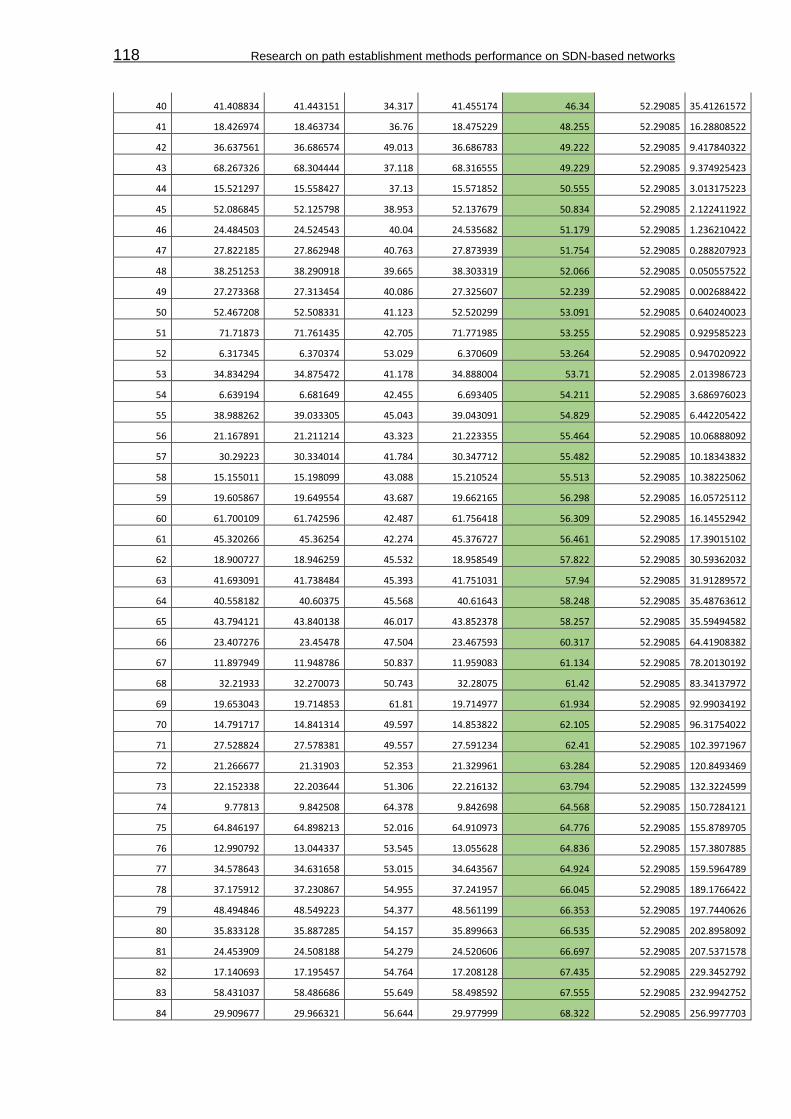
118 Research on path establishment methods performance on SDN-based networks
40 41.408834 41.443151 34.317 41.455174 46.34 52.29085 35.41261572
41 18.426974 18.463734 36.76 18.475229 48.255 52.29085 16.28808522
42 36.637561 36.686574 49.013 36.686783 49.222 52.29085 9.417840322
43 68.267326 68.304444 37.118 68.316555 49.229 52.29085 9.374925423
44 15.521297 15.558427 37.13 15.571852 50.555 52.29085 3.013175223
45 52.086845 52.125798 38.953 52.137679 50.834 52.29085 2.122411922
46 24.484503 24.524543 40.04 24.535682 51.179 52.29085 1.236210422
47 27.822185 27.862948 40.763 27.873939 51.754 52.29085 0.288207923
48 38.251253 38.290918 39.665 38.303319 52.066 52.29085 0.050557522
49 27.273368 27.313454 40.086 27.325607 52.239 52.29085 0.002688422
50 52.467208 52.508331 41.123 52.520299 53.091 52.29085 0.640240023
51 71.71873 71.761435 42.705 71.771985 53.255 52.29085 0.929585223
52 6.317345 6.370374 53.029 6.370609 53.264 52.29085 0.947020922
53 34.834294 34.875472 41.178 34.888004 53.71 52.29085 2.013986723
54 6.639194 6.681649 42.455 6.693405 54.211 52.29085 3.686976023
55 38.988262 39.033305 45.043 39.043091 54.829 52.29085 6.442205422
56 21.167891 21.211214 43.323 21.223355 55.464 52.29085 10.06888092
57 30.29223 30.334014 41.784 30.347712 55.482 52.29085 10.18343832
58 15.155011 15.198099 43.088 15.210524 55.513 52.29085 10.38225062
59 19.605867 19.649554 43.687 19.662165 56.298 52.29085 16.05725112
60 61.700109 61.742596 42.487 61.756418 56.309 52.29085 16.14552942
61 45.320266 45.36254 42.274 45.376727 56.461 52.29085 17.39015102
62 18.900727 18.946259 45.532 18.958549 57.822 52.29085 30.59362032
63 41.693091 41.738484 45.393 41.751031 57.94 52.29085 31.91289572
64 40.558182 40.60375 45.568 40.61643 58.248 52.29085 35.48763612
65 43.794121 43.840138 46.017 43.852378 58.257 52.29085 35.59494582
66 23.407276 23.45478 47.504 23.467593 60.317 52.29085 64.41908382
67 11.897949 11.948786 50.837 11.959083 61.134 52.29085 78.20130192
68 32.21933 32.270073 50.743 32.28075 61.42 52.29085 83.34137972
69 19.653043 19.714853 61.81 19.714977 61.934 52.29085 92.99034192
70 14.791717 14.841314 49.597 14.853822 62.105 52.29085 96.31754022
71 27.528824 27.578381 49.557 27.591234 62.41 52.29085 102.3971967
72 21.266677 21.31903 52.353 21.329961 63.284 52.29085 120.8493469
73 22.152338 22.203644 51.306 22.216132 63.794 52.29085 132.3224599
74 9.77813 9.842508 64.378 9.842698 64.568 52.29085 150.7284121
75 64.846197 64.898213 52.016 64.910973 64.776 52.29085 155.8789705
76 12.990792 13.044337 53.545 13.055628 64.836 52.29085 157.3807885
77 34.578643 34.631658 53.015 34.643567 64.924 52.29085 159.5964789
78 37.175912 37.230867 54.955 37.241957 66.045 52.29085 189.1766422
79 48.494846 48.549223 54.377 48.561199 66.353 52.29085 197.7440626
80 35.833128 35.887285 54.157 35.899663 66.535 52.29085 202.8958092
81 24.453909 24.508188 54.279 24.520606 66.697 52.29085 207.5371578
82 17.140693 17.195457 54.764 17.208128 67.435 52.29085 229.3452792
83 58.431037 58.486686 55.649 58.498592 67.555 52.29085 232.9942752
84 29.909677 29.966321 56.644 29.977999 68.322 52.29085 256.9977703

Appendix H:Measurements tables 119
85 29.861664 29.918291 56.627 29.930017 68.353 52.29085 257.9926626
86 7.633285 7.689635 56.35 7.701918 68.633 52.29085 267.0658666
87 55.173106 55.230897 57.791 55.242726 69.62 52.29085 300.2994397
88 16.547131 16.604245 57.114 16.616803 69.672 52.29085 302.1043753
89 39.231334 39.289853 58.519 39.301074 69.74 52.29085 304.4728357
90 47.892406 47.949856 57.45 47.962261 69.855 52.29085 308.4993652
91 16.685175 16.742663 57.488 16.755182 70.007 52.29085 313.8619708
92 17.39471 17.452004 57.294 17.465073 70.363 52.29085 326.6026056
93 39.324909 39.383556 58.647 39.395575 70.666 52.29085 337.6461375
94 7.968298 8.027919 59.621 8.039866 71.568 52.29085 371.6085121
95 26.108382 26.166861 58.479 26.180169 71.787 52.29085 380.0998648
96 12.325165 12.385269 60.104 12.397673 72.508 52.29085 408.7331541
97 23.554778 23.616339 61.561 23.627732 72.954 52.29085 426.9657679
98 32.416407 32.477438 61.031 32.490021 73.614 52.29085 454.6767259
99 36.884485 36.946364 61.879 36.959347 74.862 52.29085 509.4568123
100 4.870121 4.93507 64.949 4.947873 77.752 52.29085 648.2701593
Annex Table 14 - PF static path confidence interval
Sum (Xi-X)² 18525.01717
Variance 187.1213855
Smp Std Dev 13.67923191
conf Level 0.95
α 0.05
DF 99
tα 1.984216952
Err Margin 2.714256383
ConfInt high 55.00510638
ConfInt low 49.57659362
Annex 36 - PF static path Quantile-Quantile plot
IV. Network events Annex Table 15 - SR network events measurements
Segment Routing
Samples (i)
PortStatus msg (s)
1st FlowMod
(s)
Last FlowMod
(s) Proc Time
Xi (ms) samp mean
X (ms) (Xi-X)² Resp Time
Xi (ms) samp mean
X (ms) (Xi-X)²
1 1640.0934
3 1640.2077
94 1640.2913
2 114.364 122.39923 64.5649
2115 197.89 265.32677 4547.71
7948
2 1348.9677
13 1349.0819
56 1349.1664
1 114.243 122.39923 66.5240
8781 198.697 265.32677 4439.52
625
3 1691.9117
86 1692.0270
11 1692.1135
28 115.225 122.39923 51.4695
7609 201.742 265.32677 4043.02
2976
0
20
40
60
80
100
-3 -2 -1 0 1 2 3
Quantile-Quantile Plot Static Path PF
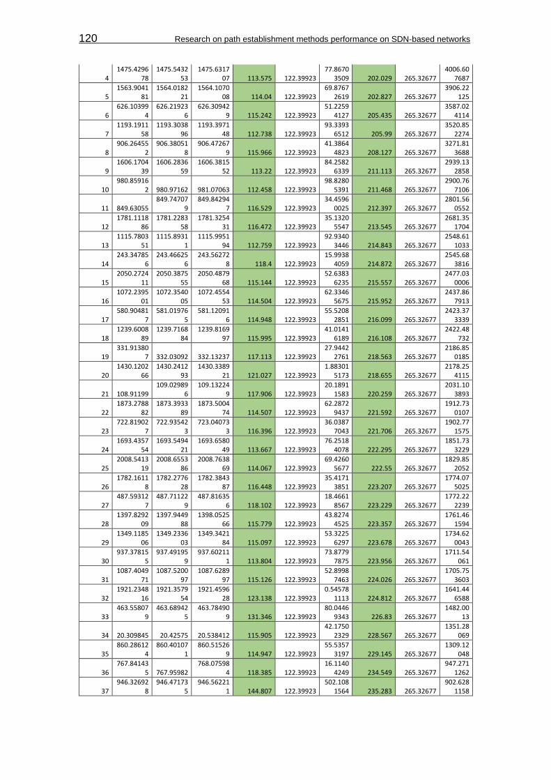
120 Research on path establishment methods performance on SDN-based networks
4 1475.4296
78 1475.5432
53 1475.6317
07 113.575 122.39923 77.8670
3509 202.029 265.32677 4006.60
7687
5 1563.9041
81 1564.0182
21 1564.1070
08 114.04 122.39923 69.8767
2619 202.827 265.32677 3906.22
125
6 626.10399
4 626.21923
6 626.30942
9 115.242 122.39923 51.2259
4127 205.435 265.32677 3587.02
4114
7 1193.1911
58 1193.3038
96 1193.3971
48 112.738 122.39923 93.3393
6512 205.99 265.32677 3520.85
2274
8 906.26455
2 906.38051
8 906.47267
9 115.966 122.39923 41.3864
4823 208.127 265.32677 3271.81
3688
9 1606.1704
39 1606.2836
59 1606.3815
52 113.22 122.39923 84.2582
6339 211.113 265.32677 2939.13
2858
10 980.85916
2 980.97162 981.07063 112.458 122.39923 98.8280
5391 211.468 265.32677 2900.76
7106
11 849.63055 849.74707
9 849.84294
7 116.529 122.39923 34.4596
0025 212.397 265.32677 2801.56
0552
12 1781.1118
86 1781.2283
58 1781.3254
31 116.472 122.39923 35.1320
5547 213.545 265.32677 2681.35
1704
13 1115.7803
51 1115.8931
1 1115.9951
94 112.759 122.39923 92.9340
3446 214.843 265.32677 2548.61
1033
14 243.34785
6 243.46625
6 243.56272
8 118.4 122.39923 15.9938
4059 214.872 265.32677 2545.68
3816
15 2050.2724
11 2050.3875
55 2050.4879
68 115.144 122.39923 52.6383
6235 215.557 265.32677 2477.03
0006
16 1072.2395
01 1072.3540
05 1072.4554
53 114.504 122.39923 62.3346
5675 215.952 265.32677 2437.86
7913
17 580.90481
7 581.01976
5 581.12091
6 114.948 122.39923 55.5208
2851 216.099 265.32677 2423.37
3339
18 1239.6008
89 1239.7168
84 1239.8169
97 115.995 122.39923 41.0141
6189 216.108 265.32677 2422.48
732
19 331.91380
7 332.03092 332.13237 117.113 122.39923 27.9442
2761 218.563 265.32677 2186.85
0185
20 1430.1202
66 1430.2412
93 1430.3389
21 121.027 122.39923 1.88301
5173 218.655 265.32677 2178.25
4115
21 108.91199 109.02989
6 109.13224
9 117.906 122.39923 20.1891
1583 220.259 265.32677 2031.10
3893
22 1873.2788
82 1873.3933
89 1873.5004
74 114.507 122.39923 62.2872
9437 221.592 265.32677 1912.73
0107
23 722.81902
7 722.93542
3 723.04073
3 116.396 122.39923 36.0387
7043 221.706 265.32677 1902.77
1575
24 1693.4357
54 1693.5494
21 1693.6580
49 113.667 122.39923 76.2518
4078 222.295 265.32677 1851.73
3229
25 2008.5413
19 2008.6553
86 2008.7638
69 114.067 122.39923 69.4260
5677 222.55 265.32677 1829.85
2052
26 1782.1611
8 1782.2776
28 1782.3843
87 116.448 122.39923 35.4171
3851 223.207 265.32677 1774.07
5025
27 487.59312
7 487.71122
9 487.81635
6 118.102 122.39923 18.4661
8567 223.229 265.32677 1772.22
2239
28 1397.8292
09 1397.9449
88 1398.0525
66 115.779 122.39923 43.8274
4525 223.357 265.32677 1761.46
1594
29 1349.1185
06 1349.2336
03 1349.3421
84 115.097 122.39923 53.3225
6297 223.678 265.32677 1734.62
0043
30 937.37815
5 937.49195
9 937.60211
1 113.804 122.39923 73.8779
7875 223.956 265.32677 1711.54
061
31 1087.4049
71 1087.5200
97 1087.6289
97 115.126 122.39923 52.8998
7463 224.026 265.32677 1705.75
3603
32 1921.2348
16 1921.3579
54 1921.4596
28 123.138 122.39923 0.54578
1113 224.812 265.32677 1641.44
6588
33 463.55807
9 463.68942
5 463.78490
9 131.346 122.39923 80.0446
9343 226.83 265.32677 1482.00
13
34 20.309845 20.42575 20.538412 115.905 122.39923 42.1750
2329 228.567 265.32677 1351.28
069
35 860.28612
4 860.40107
1 860.51526
9 114.947 122.39923 55.5357
3197 229.145 265.32677 1309.12
048
36 767.84143
5 767.95982 768.07598
4 118.385 122.39923 16.1140
4249 234.549 265.32677 947.271
1262
37 946.32692
8 946.47173
5 946.56221
1 144.807 122.39923 502.108
1564 235.283 265.32677 902.628
1158
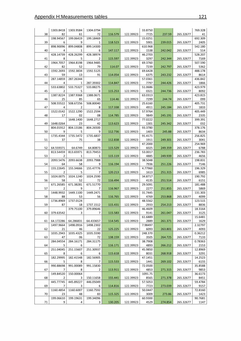
Appendix H:Measurements tables 121
38 1303.8418
82 1303.9584
61 1304.0794
72 116.579 122.39923 33.8750
7725 237.59 265.32677 769.328
41
39 198.94567
6 199.06419
9 199.18469
1 118.523 122.39923 15.0251
5901 239.015 265.32677 692.309
2405
40 898.90096
4 899.04808
1 899.14300
6 147.117 122.39923 610.968
1538 242.042 265.32677 542.180
514
41 428.14739
8 428.26299
5 428.38974
2 115.597 122.39923 46.2703
3297 242.344 265.32677 528.207
7169
42 1964.7057
82 1964.8198
52 1964.9485
79 114.07 122.39923 69.3760
7239 242.797 265.32677 507.590
5362
43 1592.2693
59 1592.3834
13 1592.5125
91 114.054 122.39923 69.6428
6375 243.232 265.32677 488.178
8614
44 287.14859
4 287.26344
1 287.39302 114.847 122.39923 57.0361
7797 244.426 265.32677 436.842
1866
45 533.63802
2 533.75327
5 533.88275
8 115.253 122.39923 51.0686
0321 244.736 265.32677 423.979
8092
46 1387.8224
25 1387.9368
85 1388.0671
65 114.46 122.39923 63.0313
7299 244.74 265.32677 423.815
099
47 508.55522
4 508.67256
2 508.80040
8 117.338 122.39923 25.6160
4911 245.184 265.32677 405.731
1833
48 1522.0142
17 1522.1290
02 1522.2594
08 114.785 122.39923 57.9764
9849 245.191 265.32677 405.449
2335
49 1648.0264 1648.1400
23 1648.2717
42 113.623 122.39923 77.0222
1301 245.342 265.32677 399.391
032
50 804.01912
9 804.13186
5 804.26500
9 112.736 122.39923 93.3780
1403 245.88 265.32677 378.176
8634
51 1735.4344
37 1735.5472
75 1735.6837
38 112.838 122.39923 91.4171
1911 249.301 265.32677 256.825
3041
52 64.559371 64.6749 64.80873 115.529 122.39923 47.2000
6025 249.359 265.32677 254.969
6788
53 813.54459
2 813.65971
1 813.79453
1 115.119 122.39923 53.0017
4885 249.939 265.32677 236.783
4656
54 2093.5476
64 2093.6638
58 2093.7988
9 116.194 122.39923 38.5048
7936 251.226 265.32677 198.831
7146
55 155.22645
2 155.34666
5 155.47776
7 120.213 122.39923 4.77960
1613 251.315 265.32677 196.329
6985
56 1024.0075
58 1024.1240
52 1024.2590
72 116.494 122.39923 34.8717
4135 251.514 265.32677 190.792
6151
57 671.26585
2 671.38281
9 671.51770
7 116.967 122.39923 29.5091
2277 251.855 265.32677 181.488
5869
58 1448.9932
88 1449.1100
53 1449.2471
56 116.765 122.39923 31.7445
4769 253.868 265.32677 131.303
4099
59 1736.8969
87 1737.0124
18 1737.1512 115.431 122.39923 48.5562
2933 254.213 265.32677 123.515
8836
60 379.63542 379.75100
3 379.89646
7 115.583 122.39923 46.4609
9141 261.047 265.32677 18.3164
3125
61 64.172286 64.286831 64.433657 114.545 122.39923 61.6889
2889 261.371 265.32677 15.6481
1629
62 1497.9664
21 1498.0916
46 1498.2302
22 125.225 122.39923 7.98497
6093 263.801 265.32677 2.32797
4093
63 1035.2943
47 1035.4325
06 1035.5590
72 138.159 122.39923 248.370
3505 264.725 265.32677 0.36212
7133
64 284.04554
5 284.16171
6 284.31175
7 116.171 122.39923 38.7908
4893 266.212 265.32677 0.78363
2153
65 251.04045
8 251.15607
6 251.30937
6 115.618 122.39923 45.9850
8031 268.918 265.32677 12.8969
3291
66 182.29995
5 182.41548
8 182.56905
7 115.533 122.39923 47.1451
1441 269.102 265.32677 14.2523
6155
67 990.88698
7 991.00089
8 991.15830
2 113.911 122.39923 72.0500
4853 271.315 265.32677 35.8588
9853
68 149.84520
2 150.00064
3 150.11658 155.441 122.39923 1091.75
8565 271.378 265.32677 36.6173
8451
69 445.77745
7 445.89227
3 446.05049
6 114.816 122.39923 57.5053
7723 273.039 265.32677 59.4784
9157
70 1160.4854
23 1160.6007
48 1160.7592
83 115.325 122.39923 50.0447
3009 273.86 265.32677 72.8160
1423
71 199.06610
9 199.19631
4 199.34096
3 130.205 122.39923 60.9300
4529 274.854 265.32677 90.7681
1147

122 Research on path establishment methods performance on SDN-based networks
72 14.09145 14.23164 14.371445 140.19 122.39923 316.511
4972 279.995 265.32677 215.156
9713
73 61.392076 61.509003 61.680708 116.927 122.39923 29.9453
0117 288.632 265.32677 543.133
7454
74 330.13365 330.32967
2 330.42403
6 196.022 122.39923 5420.31
2262 290.386 265.32677 627.965
0082
75 108.85825
9 108.97316
3 109.14883
9 114.904 122.39923 56.1784
7275 290.58 265.32677 637.725
6254
76 525.72284
2 525.83916
7 526.01584
8 116.325 122.39923 36.8962
7009 293.006 265.32677 766.139
7734
77 1256.8462
85 1256.9625
17 1257.1427
17 116.232 122.39923 38.0347
2587 296.432 265.32677 967.535
3333
78 1542.0952
98 1542.2185
1 1542.3937
58 123.212 122.39923 0.66059
5073 298.46 265.32677 1097.81
093
79 210.30611
3 210.42178
7 210.60880
2 115.674 122.39923 45.2287
1855 302.689 265.32677 1395.93
6231
80 107.10490
8 107.22704
8 107.40773
6 122.14 122.39923 0.06720
0193 302.828 265.32677 1406.34
2252
81 205.27734
9 205.49424
5 205.58253 216.896 122.39923 8929.63
954 305.181 265.32677 1588.35
9649
82 556.75999
8 556.89371
5 557.06971
7 133.717 122.39923 128.091
9178 309.719 265.32677 1970.67
0084
83 37.202187 37.344628 37.526748 142.441 122.39923 401.672
5447 324.561 265.32677 3508.69
4004
84 257.61717
9 257.72996
4 257.94281 112.785 122.39923 92.4334
1849 325.631 265.32677 3636.60
0156
85 380.92484 381.04249
6 381.25306
9 117.656 122.39923 22.4982
3083 328.229 265.32677 3956.69
0539
86 159.47383
9 159.58889 159.80374
3 115.051 122.39923 53.9964
8413 329.904 265.32677 4170.21
8634
87 499.33793
1 499.47593
9 499.66916
9 138.008 122.39923 243.633
7009 331.238 265.32677 4344.29
024
88 1212.4560
05 1212.6016
77 1212.7930
05 145.672 122.39923 541.621
8235 337 265.32677 5137.05
1899
89 400.76951 400.88262
8 401.12177
2 113.118 122.39923 86.1412
3031 352.262 265.32677 7557.73
4215
90 369.39724
9 369.50948
1 369.75059
2 112.232 122.39923 103.372
5659 353.343 265.32677 7746.85
6743
91 228.90226
1 229.01938
9 229.25719
7 117.128 122.39923 27.7858
6571 354.936 265.32677 8029.81
4101
92 474.56484
3 474.69530
2 474.92935
1 130.459 122.39923 64.9598
9245 364.508 265.32677 9836.91
6384
93 1285.6857
36 1285.8009
06 1286.0595
91 115.17 122.39923 52.2617
6639 373.855 265.32677 11778.3
7671
94 164.69313
2 164.82736
1 165.07060
4 134.229 122.39923 139.943
4583 377.472 265.32677 12576.5
5261
95 300.89542 301.02039
6 301.27555
2 124.976 122.39923 6.63974
3633 380.132 265.32677 13180.2
4084
96 153.07964
7 153.34400
8 153.47086
2 264.361 122.39923 20153.1
4414 391.215 265.32677 15847.8
4645
97 330.37338
9 330.49521
9 330.77362
4 121.83 122.39923 0.32402
2793 400.235 265.32677 18200.2
3052
98 1827.1119
15 1827.2284
13 1827.5302
65 116.498 122.39923 34.8245
1551 418.35 265.32677 23416.1
0892
99 352.11872
9 352.23610
7 352.53910
3 117.378 122.39923 25.2127
5071 420.374 265.32677 24039.6
4353
100 378.60167
5 378.72191
4 379.03751
8 120.239 122.39923 4.66659
3653 435.843 265.32677 29075.7
8469

Appendix H:Measurements tables 123
Annex Table 16 - SR network events response confidence interval
Sum (Xi-X)² 315275.9
Variance 3184.605
Smp Std Dev 56.43231
conf Level 0.95
α 0.05
DF 99
tα 1.984217
Err Margin 11.19739
Resp Time (ms)
ConfInt high 276.5242
ConfInt low 254.1294
Annex Table 17 - SR network events processing confidence interval
Sum (Xi-X)² 42893.01
Variance 433.2627
Smp Std Dev 20.81496
conf Level 0.95
α 0.05
DF 99
tα 1.984217
Err Margin 4.13014
Proc Time (ms)
ConfInt high 126.5294
ConfInt low 118.2691
Annex 37 - SR network events Quantile-Quantile plot Annex Table 18 - PF network events measurements
Intent Forwarding
samples (i)
Port status msg (s)
1st FlowMod
(s)
Last FlowMod
(s) Proc Time
Xi (ms) samp mean
X (ms) (Xi-X)² Resp Time
Xi (ms) samp mean
X (ms) (Xi-X)²
1 817.97760
7 818.00139
5 818.00616
1 23.788 25.22613 2.06821
7897 28.554 40.75343 148.826
0923
2 387.37108
1 387.39432
6 387.40717
4 23.245 25.22613 3.92487
6077 36.093 40.75343 21.7196
0778
3 287.88295
9 287.90683 287.91914 23.871 25.22613 1.83637
7317 36.181 40.75343 20.9071
161
4 190.05928
2 190.08223
7 190.09548
2 22.955 25.22613 5.15803
1477 36.2 40.75343 20.7337
2476
5 319.09123 319.11438
5 319.12745 23.155 25.22613 4.28957
9477 36.22 40.75343 20.5519
8756
6 234.35733
5 234.38030
8 234.39369
2 22.973 25.22613 5.07659
4797 36.357 40.75343 19.3285
9675
7 622.59427
4 622.61788
8 622.63070
9 23.614 25.22613 2.59896
3137 36.435 40.75343 18.6488
3767
8 736.11012
3 736.13506 736.14664
2 24.937 25.22613 0.08359
6157 36.519 40.75343 17.9303
9742
9 510.22693
5 510.25114
2 510.26347
8 24.207 25.22613 1.03862
5957 36.543 40.75343 17.7277
2078
0
100
200
300
400
500
-3 -2 -1 0 1 2 3
Quantile-Quantile Plot Network Event SR

124 Research on path establishment methods performance on SDN-based networks
10 237.84182
6 237.86564
5 237.87843
8 23.819 25.22613 1.98001
4837 36.612 40.75343 17.1514
4244
11 23.58896 23.612715 23.625603 23.755 25.22613 2.16422
3477 36.643 40.75343 16.8956
3478
12 57.503059 57.526921 57.53972 23.862 25.22613 1.86085
0657 36.661 40.75343 16.7479
833
13 469.31183
9 469.33630
7 469.34853
3 24.468 25.22613 0.57476
1097 36.694 40.75343 16.4789
7193
14 647.01435
5 647.03784
3 647.05109
5 23.488 25.22613 3.02109
5897 36.74 40.75343 16.1076
2036
15 844.29881
1 844.32236
1 844.33564
9 23.55 25.22613 2.80941
1777 36.838 40.75343 15.3305
9208
16 331.20908
5 331.23290
7 331.24597
1 23.822 25.22613 1.97158
1057 36.886 40.75343 14.9570
1481
17 752.60402
6 752.62809
8 752.64103
2 24.072 25.22613 1.33201
6057 37.006 40.75343 14.0432
316
18 88.555757 88.580159 88.592773 24.402 25.22613 0.67919
0257 37.016 40.75343 13.9683
83
19 270.53108
2 270.55445
7 270.56823
4 23.375 25.22613 3.42668
2277 37.152 40.75343 12.9702
9804
20 629.00927 629.03319
3 629.04644
9 23.923 25.22613 1.69814
7797 37.179 40.75343 12.7765
4982
21 693.73626
7 693.76029
7 693.77344
6 24.03 25.22613 1.43072
6977 37.179 40.75343 12.7765
4982
22 596.09490
6 596.11849
8 596.13208
9 23.592 25.22613 2.67038
0857 37.183 40.75343 12.7479
7039
23 557.79444
2 557.81870
5 557.83165
7 24.263 25.22613 0.92761
9397 37.215 40.75343 12.5204
8687
24 495.78070
6 495.80471
1 495.81805
4 24.005 25.22613 1.49115
8477 37.348 40.75343 11.5969
5348
25 87.892372 87.917393 87.92977 25.021 25.22613 0.04207
8317 37.398 40.75343 11.2589
1048
26 642.58163
2 642.60600
3 642.61909
3 24.371 25.22613 0.73124
7317 37.461 40.75343 10.8400
953
27 654.63084
7 654.65336 654.66831
6 22.513 25.22613 7.36107
4397 37.469 40.75343 10.7874
8042
28 603.78554
4 603.81143
6 603.82302
5 25.892 25.22613 0.44338
2857 37.481 40.75343 10.7087
981
29 349.13679
4 349.16044 349.17439 23.646 25.22613 2.49681
0817 37.596 40.75343 9.96936
4205
30 22.760499 22.784196 22.798154 23.697 25.22613 2.33823
8557 37.655 40.75343 9.60026
8465
31 324.54069
5 324.5662 324.57843
2 25.505 25.22613 0.07776
8477 37.737 40.75343 9.09884
9945
32 166.59921
4 166.62331
5 166.63696
2 24.101 25.22613 1.26591
7517 37.748 40.75343 9.03260
9485
33 487.54490
6 487.56835
9 487.58272
2 23.453 25.22613 3.14398
9997 37.816 40.75343 8.62849
5005
34 390.48399
8 390.50772
2 390.52184
5 23.724 25.22613 2.25639
4537 37.847 40.75343 8.44733
5345
35 396.98152 397.00554
4 397.01938
5 24.024 25.22613 1.44511
6537 37.865 40.75343 8.34302
7865
36 245.22944
3 245.25361
4 245.26732
2 24.171 25.22613 1.11329
9317 37.879 40.75343 8.26234
7825
37 619.24892
6 619.27223
6 619.28687
9 23.31 25.22613 3.67155
4177 37.953 40.75343 7.84240
8185
38 119.81270
6 119.83615
2 119.85077
1 23.446 25.22613 3.16886
2817 38.065 40.75343 7.22765
5865
39 526.74688
3 526.77356
7 526.78497
1 26.684 25.22613 2.12538
4937 38.088 40.75343 7.10451
7085
40 163.37567
5 163.40025
6 163.41383
4 24.581 25.22613 0.41619
2717 38.159 40.75343 6.73106
7025
41 655.39286 655.41674
9 655.43106 23.889 25.22613 1.78791
6637 38.2 40.75343 6.52000
4765
42 612.99604
5 613.02016
4 613.03425
5 24.119 25.22613 1.22573
6837 38.21 40.75343 6.46903
6165
43 435.19138
1 435.21528
7 435.22959
8 23.906 25.22613 1.74274
3217 38.217 40.75343 6.43347
7145
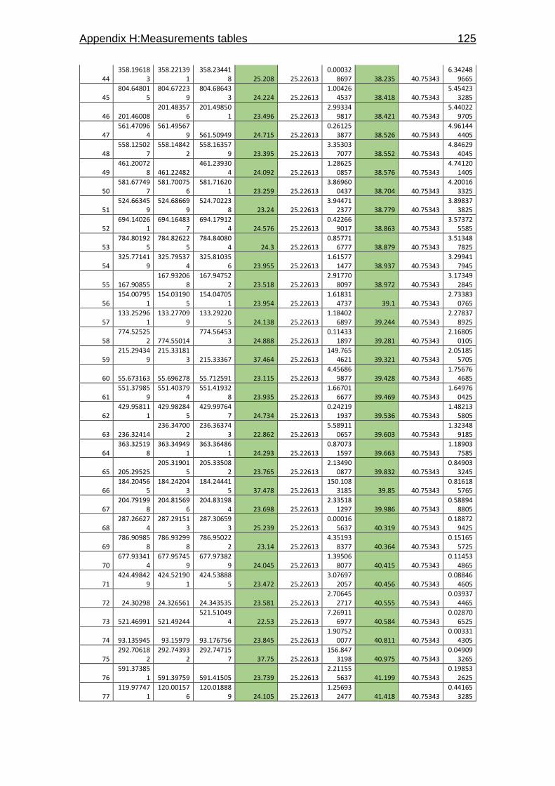
Appendix H:Measurements tables 125
44 358.19618
3 358.22139
1 358.23441
8 25.208 25.22613 0.00032
8697 38.235 40.75343 6.34248
9665
45 804.64801
5 804.67223
9 804.68643
3 24.224 25.22613 1.00426
4537 38.418 40.75343 5.45423
3285
46 201.46008 201.48357
6 201.49850
1 23.496 25.22613 2.99334
9817 38.421 40.75343 5.44022
9705
47 561.47096
4 561.49567
9 561.50949 24.715 25.22613 0.26125
3877 38.526 40.75343 4.96144
4405
48 558.12502
7 558.14842
2 558.16357
9 23.395 25.22613 3.35303
7077 38.552 40.75343 4.84629
4045
49 461.20072
8 461.22482 461.23930
4 24.092 25.22613 1.28625
0857 38.576 40.75343 4.74120
1405
50 581.67749
7 581.70075
6 581.71620
1 23.259 25.22613 3.86960
0437 38.704 40.75343 4.20016
3325
51 524.66345
9 524.68669
9 524.70223
8 23.24 25.22613 3.94471
2377 38.779 40.75343 3.89837
3825
52 694.14026
1 694.16483
7 694.17912
4 24.576 25.22613 0.42266
9017 38.863 40.75343 3.57372
5585
53 784.80192
5 784.82622
5 784.84080
4 24.3 25.22613 0.85771
6777 38.879 40.75343 3.51348
7825
54 325.77141
9 325.79537
4 325.81035
6 23.955 25.22613 1.61577
1477 38.937 40.75343 3.29941
7945
55 167.90855 167.93206
8 167.94752
2 23.518 25.22613 2.91770
8097 38.972 40.75343 3.17349
2845
56 154.00795
1 154.03190
5 154.04705
1 23.954 25.22613 1.61831
4737 39.1 40.75343 2.73383
0765
57 133.25296
1 133.27709
9 133.29220
5 24.138 25.22613 1.18402
6897 39.244 40.75343 2.27837
8925
58 774.52525
2 774.55014 774.56453
3 24.888 25.22613 0.11433
1897 39.281 40.75343 2.16805
0105
59 215.29434
9 215.33181
3 215.33367 37.464 25.22613 149.765
4621 39.321 40.75343 2.05185
5705
60 55.673163 55.696278 55.712591 23.115 25.22613 4.45686
9877 39.428 40.75343 1.75676
4685
61 551.37985
9 551.40379
4 551.41932
8 23.935 25.22613 1.66701
6677 39.469 40.75343 1.64976
0425
62 429.95811
1 429.98284
5 429.99764
7 24.734 25.22613 0.24219
1937 39.536 40.75343 1.48213
5805
63 236.32414 236.34700
2 236.36374
3 22.862 25.22613 5.58911
0657 39.603 40.75343 1.32348
9185
64 363.32519
8 363.34949
1 363.36486
1 24.293 25.22613 0.87073
1597 39.663 40.75343 1.18903
7585
65 205.29525 205.31901
5 205.33508
2 23.765 25.22613 2.13490
0877 39.832 40.75343 0.84903
3245
66 184.20456
5 184.24204
3 184.24441
5 37.478 25.22613 150.108
3185 39.85 40.75343 0.81618
5765
67 204.79199
8 204.81569
6 204.83198
4 23.698 25.22613 2.33518
1297 39.986 40.75343 0.58894
8805
68 287.26627
4 287.29151
3 287.30659
3 25.239 25.22613 0.00016
5637 40.319 40.75343 0.18872
9425
69 786.90985
8 786.93299
8 786.95022
2 23.14 25.22613 4.35193
8377 40.364 40.75343 0.15165
5725
70 677.93341
4 677.95745
9 677.97382
9 24.045 25.22613 1.39506
8077 40.415 40.75343 0.11453
4865
71 424.49842
9 424.52190
1 424.53888
5 23.472 25.22613 3.07697
2057 40.456 40.75343 0.08846
4605
72 24.30298 24.326561 24.343535 23.581 25.22613 2.70645
2717 40.555 40.75343 0.03937
4465
73 521.46991 521.49244 521.51049
4 22.53 25.22613 7.26911
6977 40.584 40.75343 0.02870
6525
74 93.135945 93.15979 93.176756 23.845 25.22613 1.90752
0077 40.811 40.75343 0.00331
4305
75 292.70618
2 292.74393
2 292.74715
7 37.75 25.22613 156.847
3198 40.975 40.75343 0.04909
3265
76 591.37385
1 591.39759 591.41505 23.739 25.22613 2.21155
5637 41.199 40.75343 0.19853
2625
77 119.97747
1 120.00157
6 120.01888
9 24.105 25.22613 1.25693
2477 41.418 40.75343 0.44165
3285
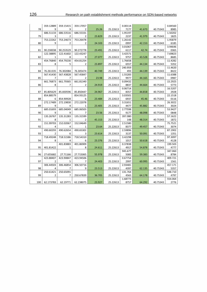
126 Research on path establishment methods performance on SDN-based networks
78 359.12889
9 359.15415
9 359.17057
2 25.26 25.22613 0.00114
7177 41.673 40.75343 0.84560
8985
79 686.51133
3 686.53516
2 686.55331
2 23.829 25.22613 1.95197
2237 41.979 40.75343 1.50202
1825
80 753.22262
9 753.24673
2 753.26478
2 24.103 25.22613 1.26142
0997 42.153 40.75343 1.95879
6185
81 90.230038 90.253529 90.272778 23.491 25.22613 3.01067
6117 42.74 40.75343 3.94646
0365
82 122.38895
1 122.41602
8 122.43247
9 27.077 25.22613 3.42571
9757 43.528 40.75343 7.69823
8685
83 454.76840
8 454.79230
5 454.81254
2 23.897 25.22613 1.76658
6557 44.134 40.75343 11.4282
5352
84 76.261335 76.302084 76.305474 40.749 25.22613 240.959
493 44.139 40.75343 11.4620
8422
85 567.41430
7 567.43828
7 567.45847
2 23.98 25.22613 1.55283
9977 44.165 40.75343 11.6388
0987
86 661.76873
8 661.79365
7 661.81340
2 24.919 25.22613 0.09432
8837 44.664 40.75343 15.2925
5773
87 85.805629 85.830596 85.850447 24.967 25.22613 0.06714
8357 44.818 40.75343 16.5207
2928
88 854.88579
6 854.90928 854.93125
6 23.484 25.22613 3.03501
6937 45.46 40.75343 22.1518
0116
89 272.17489
9 272.19830
4 272.22078
1 23.405 25.22613 3.31651
4477 45.882 40.75343 26.3022
3024
90 685.01693
9 685.04049
9 685.06503
7 23.56 25.22613 2.77598
9177 48.098 40.75343 53.9427
0848
91 135.26767
8 135.31283
1 135.31599
2 45.153 25.22613 397.080
148 48.314 40.75343 57.1622
1872
92 151.99703
4 152.02067
4 152.04649
1 23.64 25.22613 2.51580
8377 49.457 40.75343 75.7521
3074
93 490.60293
2 490.62654
6 490.65302
3 23.614 25.22613 2.59896
3137 50.091 40.75343 87.1902
1351
94 718.49248
8 718.51586
4 718.54310
6 23.376 25.22613 3.42298
1017 50.618 40.75343 97.3097
4128
95 401.81422 401.83883
1 401.86909
8 24.611 25.22613 0.37838
4917 54.878 40.75343 199.503
4777
96 27.655682 27.71166 27.715065 55.978 25.22613 945.677
5085 59.383 40.75343 347.060
8784
97 423.88407
2 423.90847
5 423.94506
7 24.403 25.22613 0.67754
2997 60.995 40.75343 409.721
1561
98 306.44503
4 306.46854
7 306.50716
9 23.513 25.22613 2.93481
4397 62.135 40.75343 457.171
5357
99 250.61421
2 250.65091
7 250.67839 36.705 25.22613 131.764
4565 64.178 40.75343 548.710
4797
100 62.173783 62.19771 62.238075 23.927 25.22613 1.68773
8757 64.292 40.75343 554.064
2776
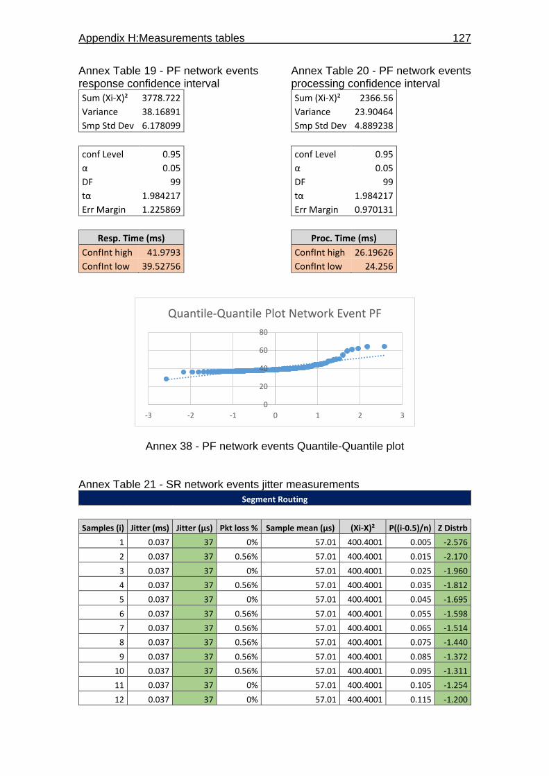
Appendix H:Measurements tables 127
Annex Table 19 - PF network events response confidence interval
Sum (Xi-X)² 3778.722
Variance 38.16891
Smp Std Dev 6.178099
conf Level 0.95
α 0.05
DF 99
tα 1.984217
Err Margin 1.225869
Resp. Time (ms)
ConfInt high 41.9793
ConfInt low 39.52756
Annex Table 20 - PF network events processing confidence interval
Sum (Xi-X)² 2366.56
Variance 23.90464
Smp Std Dev 4.889238
conf Level 0.95
α 0.05
DF 99
tα 1.984217
Err Margin 0.970131
Proc. Time (ms)
ConfInt high 26.19626
ConfInt low 24.256
Annex 38 - PF network events Quantile-Quantile plot Annex Table 21 - SR network events jitter measurements
Segment Routing
Samples (i) Jitter (ms) Jitter (μs) Pkt loss % Sample mean (µs) (Xi-X)² P((i-0.5)/n) Z Distrb
1 0.037 37 0% 57.01 400.4001 0.005 -2.576
2 0.037 37 0.56% 57.01 400.4001 0.015 -2.170
3 0.037 37 0% 57.01 400.4001 0.025 -1.960
4 0.037 37 0.56% 57.01 400.4001 0.035 -1.812
5 0.037 37 0% 57.01 400.4001 0.045 -1.695
6 0.037 37 0.56% 57.01 400.4001 0.055 -1.598
7 0.037 37 0.56% 57.01 400.4001 0.065 -1.514
8 0.037 37 0.56% 57.01 400.4001 0.075 -1.440
9 0.037 37 0.56% 57.01 400.4001 0.085 -1.372
10 0.037 37 0.56% 57.01 400.4001 0.095 -1.311
11 0.037 37 0% 57.01 400.4001 0.105 -1.254
12 0.037 37 0% 57.01 400.4001 0.115 -1.200
0
20
40
60
80
-3 -2 -1 0 1 2 3
Quantile-Quantile Plot Network Event PF

128 Research on path establishment methods performance on SDN-based networks
13 0.037 37 0.56% 57.01 400.4001 0.125 -1.150
14 0.037 37 0% 57.01 400.4001 0.135 -1.103
15 0.037 37 0% 57.01 400.4001 0.145 -1.058
16 0.037 37 0.56% 57.01 400.4001 0.155 -1.015
17 0.037 37 0% 57.01 400.4001 0.165 -0.974
18 0.037 37 0.56% 57.01 400.4001 0.175 -0.935
19 0.037 37 0% 57.01 400.4001 0.185 -0.896
20 0.037 37 0.56% 57.01 400.4001 0.195 -0.860
21 0.037 37 0.56% 57.01 400.4001 0.205 -0.824
22 0.038 38 0% 57.01 361.3801 0.215 -0.789
23 0.044 44 0% 57.01 169.2601 0.225 -0.755
24 0.045 45 1.10% 57.01 144.2401 0.235 -0.722
25 0.047 47 0.56% 57.01 100.2001 0.245 -0.690
26 0.049 49 0.56% 57.01 64.1601 0.255 -0.659
27 0.049 49 0.56% 57.01 64.1601 0.265 -0.628
28 0.05 50 0.56% 57.01 49.1401 0.275 -0.598
29 0.051 51 0% 57.01 36.1201 0.285 -0.568
30 0.051 51 0% 57.01 36.1201 0.295 -0.539
31 0.051 51 0.56% 57.01 36.1201 0.305 -0.510
32 0.051 51 0.56% 57.01 36.1201 0.315 -0.482
33 0.051 51 0.56% 57.01 36.1201 0.325 -0.454
34 0.051 51 0% 57.01 36.1201 0.335 -0.426
35 0.051 51 0% 57.01 36.1201 0.345 -0.399
36 0.051 51 0% 57.01 36.1201 0.355 -0.372
37 0.051 51 0.56% 57.01 36.1201 0.365 -0.345
38 0.051 51 0% 57.01 36.1201 0.375 -0.319
39 0.051 51 0.56% 57.01 36.1201 0.385 -0.292
40 0.051 51 0% 57.01 36.1201 0.395 -0.266
41 0.051 51 0% 57.01 36.1201 0.405 -0.240
42 0.051 51 0.56% 57.01 36.1201 0.415 -0.215
43 0.051 51 0.56% 57.01 36.1201 0.425 -0.189
44 0.051 51 0% 57.01 36.1201 0.435 -0.164
45 0.051 51 0.56% 57.01 36.1201 0.445 -0.138
46 0.051 51 0% 57.01 36.1201 0.455 -0.113
47 0.051 51 0.56% 57.01 36.1201 0.465 -0.088
48 0.051 51 0.56% 57.01 36.1201 0.475 -0.063
49 0.052 52 1.10% 57.01 25.1001 0.485 -0.038
50 0.052 52 0% 57.01 25.1001 0.495 -0.013
51 0.053 53 0.56% 57.01 16.0801 0.505 0.013
52 0.053 53 0% 57.01 16.0801 0.515 0.038
53 0.054 54 0.56% 57.01 9.0601 0.525 0.063
54 0.054 54 0.56% 57.01 9.0601 0.535 0.088
55 0.054 54 0.56% 57.01 9.0601 0.545 0.113
56 0.054 54 0.56% 57.01 9.0601 0.555 0.138
57 0.054 54 0% 57.01 9.0601 0.565 0.164

Appendix H:Measurements tables 129
58 0.054 54 0% 57.01 9.0601 0.575 0.189
59 0.054 54 0.56% 57.01 9.0601 0.585 0.215
60 0.054 54 0.56% 57.01 9.0601 0.595 0.240
61 0.054 54 0% 57.01 9.0601 0.605 0.266
62 0.054 54 0% 57.01 9.0601 0.615 0.292
63 0.054 54 0% 57.01 9.0601 0.625 0.319
64 0.054 54 0.56% 57.01 9.0601 0.635 0.345
65 0.054 54 0.56% 57.01 9.0601 0.645 0.372
66 0.054 54 0.56% 57.01 9.0601 0.655 0.399
67 0.054 54 0.56% 57.01 9.0601 0.665 0.426
68 0.054 54 0.56% 57.01 9.0601 0.675 0.454
69 0.054 54 0.56% 57.01 9.0601 0.685 0.482
70 0.054 54 0.56% 57.01 9.0601 0.695 0.510
71 0.054 54 0% 57.01 9.0601 0.705 0.539
72 0.054 54 0.56% 57.01 9.0601 0.715 0.568
73 0.057 57 0.56% 57.01 1E-04 0.725 0.598
74 0.057 57 0% 57.01 1E-04 0.735 0.628
75 0.058 58 0% 57.01 0.9801 0.745 0.659
76 0.059 59 0% 57.01 3.9601 0.755 0.690
77 0.06 60 0.56% 57.01 8.9401 0.765 0.722
78 0.061 61 0.56% 57.01 15.9201 0.775 0.755
79 0.062 62 0% 57.01 24.9001 0.785 0.789
80 0.062 62 0.56% 57.01 24.9001 0.795 0.824
81 0.063 63 0% 57.01 35.8801 0.805 0.860
82 0.066 66 0.56% 57.01 80.8201 0.815 0.896
83 0.067 67 0.56% 57.01 99.8001 0.825 0.935
84 0.069 69 0% 57.01 143.7601 0.835 0.974
85 0.069 69 0% 57.01 143.7601 0.845 1.015
86 0.07 70 0% 57.01 168.7401 0.855 1.058
87 0.07 70 0% 57.01 168.7401 0.865 1.103
88 0.071 71 0.56% 57.01 195.7201 0.875 1.150
89 0.075 75 0.56% 57.01 323.6401 0.885 1.200
90 0.079 79 0.56% 57.01 483.5601 0.895 1.254
91 0.079 79 0% 57.01 483.5601 0.905 1.311
92 0.08 80 0% 57.01 528.5401 0.915 1.372
93 0.09 90 0% 57.01 1088.3401 0.925 1.440
94 0.098 98 0% 57.01 1680.1801 0.935 1.514
95 0.105 105 1.10% 57.01 2303.0401 0.945 1.598
96 0.116 116 0.56% 57.01 3479.8201 0.955 1.695
97 0.117 117 0.56% 57.01 3598.8001 0.965 1.812
98 0.138 138 1.10% 57.01 6559.3801 0.975 1.960
99 0.146 146 0.56% 57.01 7919.2201 0.985 2.170
100 0.148 148 0% 57.01 8279.1801 0.995 2.576
loss mean 0.003408
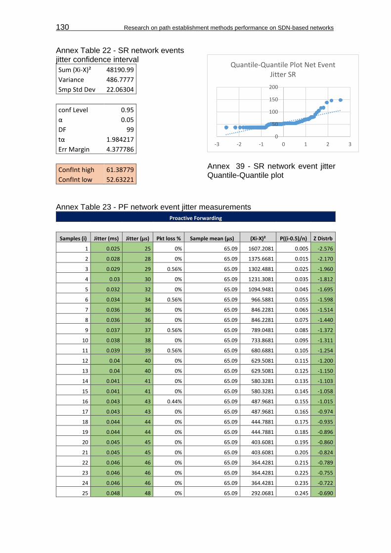
130 Research on path establishment methods performance on SDN-based networks
Annex Table 22 - SR network events jitter confidence interval
Sum (Xi-X)² 48190.99
Variance 486.7777
Smp Std Dev 22.06304
conf Level 0.95
α 0.05
DF 99
tα 1.984217
Err Margin 4.377786
ConfInt high 61.38779
ConfInt low 52.63221
Annex 39 - SR network event jitter Quantile-Quantile plot
Annex Table 23 - PF network event jitter measurements
Proactive Forwarding
Samples (i) Jitter (ms) Jitter (μs) Pkt loss % Sample mean (µs) (Xi-X)² P((i-0.5)/n) Z Distrb
1 0.025 25 0% 65.09 1607.2081 0.005 -2.576
2 0.028 28 0% 65.09 1375.6681 0.015 -2.170
3 0.029 29 0.56% 65.09 1302.4881 0.025 -1.960
4 0.03 30 0% 65.09 1231.3081 0.035 -1.812
5 0.032 32 0% 65.09 1094.9481 0.045 -1.695
6 0.034 34 0.56% 65.09 966.5881 0.055 -1.598
7 0.036 36 0% 65.09 846.2281 0.065 -1.514
8 0.036 36 0% 65.09 846.2281 0.075 -1.440
9 0.037 37 0.56% 65.09 789.0481 0.085 -1.372
10 0.038 38 0% 65.09 733.8681 0.095 -1.311
11 0.039 39 0.56% 65.09 680.6881 0.105 -1.254
12 0.04 40 0% 65.09 629.5081 0.115 -1.200
13 0.04 40 0% 65.09 629.5081 0.125 -1.150
14 0.041 41 0% 65.09 580.3281 0.135 -1.103
15 0.041 41 0% 65.09 580.3281 0.145 -1.058
16 0.043 43 0.44% 65.09 487.9681 0.155 -1.015
17 0.043 43 0% 65.09 487.9681 0.165 -0.974
18 0.044 44 0% 65.09 444.7881 0.175 -0.935
19 0.044 44 0% 65.09 444.7881 0.185 -0.896
20 0.045 45 0% 65.09 403.6081 0.195 -0.860
21 0.045 45 0% 65.09 403.6081 0.205 -0.824
22 0.046 46 0% 65.09 364.4281 0.215 -0.789
23 0.046 46 0% 65.09 364.4281 0.225 -0.755
24 0.046 46 0% 65.09 364.4281 0.235 -0.722
25 0.048 48 0% 65.09 292.0681 0.245 -0.690
0
50
100
150
200
-3 -2 -1 0 1 2 3
Quantile-Quantile Plot Net Event Jitter SR

Appendix H:Measurements tables 131
26 0.048 48 0.56% 65.09 292.0681 0.255 -0.659
27 0.048 48 0.56% 65.09 292.0681 0.265 -0.628
28 0.048 48 0.56% 65.09 292.0681 0.275 -0.598
29 0.049 49 0% 65.09 258.8881 0.285 -0.568
30 0.049 49 0.56% 65.09 258.8881 0.295 -0.539
31 0.049 49 0.56% 65.09 258.8881 0.305 -0.510
32 0.049 49 0% 65.09 258.8881 0.315 -0.482
33 0.05 50 0.56% 65.09 227.7081 0.325 -0.454
34 0.051 51 0% 65.09 198.5281 0.335 -0.426
35 0.052 52 0.56% 65.09 171.3481 0.345 -0.399
36 0.053 53 0.44% 65.09 146.1681 0.355 -0.372
37 0.053 53 0% 65.09 146.1681 0.365 -0.345
38 0.053 53 0% 65.09 146.1681 0.375 -0.319
39 0.053 53 0% 65.09 146.1681 0.385 -0.292
40 0.055 55 0.56% 65.09 101.8081 0.395 -0.266
41 0.055 55 0% 65.09 101.8081 0.405 -0.240
42 0.055 55 0.56% 65.09 101.8081 0.415 -0.215
43 0.056 56 0% 65.09 82.6281 0.425 -0.189
44 0.056 56 0% 65.09 82.6281 0.435 -0.164
45 0.057 57 0% 65.09 65.4481 0.445 -0.138
46 0.057 57 0% 65.09 65.4481 0.455 -0.113
47 0.058 58 0% 65.09 50.2681 0.465 -0.088
48 0.058 58 0.56% 65.09 50.2681 0.475 -0.063
49 0.059 59 0% 65.09 37.0881 0.485 -0.038
50 0.059 59 0% 65.09 37.0881 0.495 -0.013
51 0.059 59 0% 65.09 37.0881 0.505 0.013
52 0.059 59 0% 65.09 37.0881 0.515 0.038
53 0.06 60 0% 65.09 25.9081 0.525 0.063
54 0.061 61 0% 65.09 16.7281 0.535 0.088
55 0.061 61 0% 65.09 16.7281 0.545 0.113
56 0.062 62 0.56% 65.09 9.5481 0.555 0.138
57 0.062 62 0% 65.09 9.5481 0.565 0.164
58 0.062 62 0.56% 65.09 9.5481 0.575 0.189
59 0.062 62 0% 65.09 9.5481 0.585 0.215
60 0.064 64 0% 65.09 1.1881 0.595 0.240
61 0.064 64 0% 65.09 1.1881 0.605 0.266
62 0.064 64 0% 65.09 1.1881 0.615 0.292
63 0.064 64 0% 65.09 1.1881 0.625 0.319
64 0.065 65 0% 65.09 0.0081 0.635 0.345
65 0.066 66 0% 65.09 0.8281 0.645 0.372
66 0.067 67 0% 65.09 3.6481 0.655 0.399
67 0.067 67 0.56% 65.09 3.6481 0.665 0.426
68 0.067 67 0% 65.09 3.6481 0.675 0.454
69 0.068 68 0% 65.09 8.4681 0.685 0.482
70 0.069 69 0% 65.09 15.2881 0.695 0.510
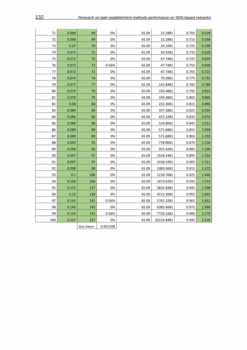
132 Research on path establishment methods performance on SDN-based networks
71 0.069 69 0% 65.09 15.2881 0.705 0.539
72 0.069 69 0% 65.09 15.2881 0.715 0.568
73 0.07 70 0% 65.09 24.1081 0.725 0.598
74 0.071 71 0% 65.09 34.9281 0.735 0.628
75 0.072 72 0% 65.09 47.7481 0.745 0.659
76 0.072 72 0.56% 65.09 47.7481 0.755 0.690
77 0.072 72 0% 65.09 47.7481 0.765 0.722
78 0.074 74 0% 65.09 79.3881 0.775 0.755
79 0.077 77 0% 65.09 141.8481 0.785 0.789
80 0.079 79 0% 65.09 193.4881 0.795 0.824
81 0.079 79 0% 65.09 193.4881 0.805 0.860
82 0.08 80 0% 65.09 222.3081 0.815 0.896
83 0.084 84 0% 65.09 357.5881 0.825 0.935
84 0.086 86 0% 65.09 437.2281 0.835 0.974
85 0.088 88 0% 65.09 524.8681 0.845 1.015
86 0.089 89 0% 65.09 571.6881 0.855 1.058
87 0.089 89 0% 65.09 571.6881 0.865 1.103
88 0.093 93 0% 65.09 778.9681 0.875 1.150
89 0.096 96 0% 65.09 955.4281 0.885 1.200
90 0.097 97 0% 65.09 1018.2481 0.895 1.254
91 0.097 97 0% 65.09 1018.2481 0.905 1.311
92 0.098 98 0% 65.09 1083.0681 0.915 1.372
93 0.1 100 0% 65.09 1218.7081 0.925 1.440
94 0.106 106 0% 65.09 1673.6281 0.935 1.514
95 0.127 127 0% 65.09 3832.8481 0.945 1.598
96 0.13 130 0% 65.09 4213.3081 0.955 1.695
97 0.141 141 0.56% 65.09 5762.3281 0.965 1.812
98 0.145 145 0% 65.09 6385.6081 0.975 1.960
99 0.153 153 0.56% 65.09 7728.1681 0.985 2.170
100 0.227 227 0% 65.09 26214.8481 0.995 2.576
loss mean 0.001208

Appendix H:Measurements tables 133
Annex Table 24 - PF network event jitter confidence interval
Sum (Xi-X)² 87444.19
Variance 883.2746
Smp Std Dev 29.71994
conf Level 0.95
α 0.05
DF 99
tα 1.984217
Err Margin 5.89708
ConfInt high 70.98708
ConfInt low 59.19292
Annex 40 - PF network event jitter Quantile-Quantile plot
V. Balanced path load Annex Table 25 - balanced path load complete measurements
Intent Forwarding
samples (i)
Port status msg (s)
1st FlowMod
(s)
Last FlowMod
(s) Proc Time
Xi (ms) samp mean
X (ms) (Xi-X)² Proc Time
Xi (ms) samp mean
X (ms) (Xi-X)²
1 68.64359 68.688048 68.727009 44.458 8758.96552 7594264
1.32 83.419 9035.32265 801365
78.96
2 158.6579
13 158.68531
4 158.76606
8 27.401 8758.96552 7624021
8.97 108.155 9035.32265 796943
22.25
3 119.7694
16 119.79428
6 119.88009
9 24.87 8758.96552 7628442
4.55 110.683 9035.32265 796491
92.88
4 23.86486 23.898269 23.979446 33.409 8758.96552 7613533
6.58 114.586 9035.32265 795795
42.38
5 88.81170
7 88.856717 88.931849 45.01 8758.96552 7593302
0.8 120.142 9035.32265 794804
46.02
6 40.80777
8 40.850641 40.931166 42.863 8758.96552 7597044
3.14 123.388 9035.32265 794225
79.21
7 30.96445
8 30.989351 31.098811 24.893 8758.96552 7628402
2.78 134.353 9035.32265 792272
60.71
8 181.5991
37 181.63955 181.73591
7 40.413 8758.96552 7601315
8.04 136.78 9035.32265 791840
61.29
9 171.5137 171.54054
8 171.65362
1 26.848 8758.96552 7624987
6.38 139.921 9035.32265 791281
70.51
10 53.90192
2 53.945499 54.046684 43.577 8758.96552 7595799
7.05 144.762 9035.32265 790420
68.67
11 42.76370
4 42.802531 42.908684 38.827 8758.96552 7604081
5.81 144.98 9035.32265 790381
92.43
12 101.2134
56 101.24111
8 101.38412
4 27.662 8758.96552 7623566
1.16 170.668 9035.32265 785821
02.06
13 121.2880
23 121.32412
4 121.46114
7 36.101 8758.96552 7608836
5.43 173.124 9035.32265 785385
64.91
14 38.00778
2 38.04863 38.183524 40.848 8758.96552 7600557
3.09 175.742 9035.32265 784921
69.29
15 136.4424
18 136.47056
1 136.62515
4 28.143 8758.96552 7622726
1.88 182.736 9035.32265 783682
90.4
16 36.50500
8 36.546904 36.688602 41.896 8758.96552 7598730
1.02 183.594 9035.32265 783531
00.09
17 70.43377
8 70.463094 70.626327 29.316 8758.96552 7620678
0.74 192.549 9035.32265 781946
45.83
-50
0
50
100
150
200
250
-3 -2 -1 0 1 2 3
Quantile-Quantile Plot Net Event Jitter PF
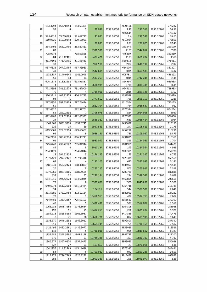
134 Research on path establishment methods performance on SDN-based networks
18 153.3794
98 153.40853
4 153.59301
5 29.036 8758.96552 7621166
9.42 213.517 9035.32265 778242
54.93
19 59.24318 59.286863 59.462717 43.683 8758.96552 7595614
9.4 219.537 9035.32265 777180
76.63
20 119.9625
9 119.99348
3 120.18961
5 30.893 8758.96552 7617924
9.91 227.025 9035.32265 775861
07.49
21 354.3493
03 363.72790
1 363.89411
5 9378.598 8758.96552 383944.
4103 9544.812 9035.32265 259579.
3978
22 708.9973
84 718.42481 718.59858
6 9427.426 8758.96552 446839.
4133 9601.202 9035.32265 320219.
4388
23 461.9161
37 471.42401
7 471.56433
1 9507.88 8758.96552 560872.
8984 9648.194 9035.32265 375611.
2917
24 957.6822
49 967.22486
4 967.33983
2 9542.615 8758.96552 614106.
5075 9657.583 9035.32265 387207.
9432
25 1131.387
59 1140.9248
43 1141.0998
34 9537.253 8758.96552 605731.
4015 9712.244 9035.32265 458222.
5141
26 604.1375
4 613.82652
4 613.96887
5 9688.984 8758.96552 864934.
3731 9831.335 9035.32265 633635.
6614
27 771.5898
76 781.32578
2 781.47900
4 9735.906 8758.96552 954412.
7015 9889.128 9035.32265 728983.
5757
28 396.3511
94 406.12875
6 406.24735
3 9777.562 8758.96552 1037538
.789 9896.159 9035.32265 741039.
2215
29 287.8256
55 297.63835
9 297.74424
2 9812.704 8758.96552 1110364
.784 9918.587 9035.32265 780155.
912
30 272.4320
52 282.22803 282.39701
7 9795.978 8758.96552 1075394
.884 9964.965 9035.32265 864234.
8989
31 812.6409
24 822.52724
6 822.65933
8 9886.322 8758.96552 1270932
.633 10018.414 9035.32265 966468.
6024
32 1041.965
926 1051.9235
15 1052.0745
39 9957.589 8758.96552 1436698
.247 10108.613 9035.32265 115195
2.175
33 619.5569
92 629.52314
3 629.66607
9 9966.151 8758.96552 1457296
.783 10109.087 9035.32265 115296
9.879
34 796.2431
02 806.22314
3 806.35713
3 9980.041 8758.96552 1491025
.328 10114.031 9035.32265 116361
1.704
35 725.6248
84 735.72622
4 735.84944
8 10101.34 8758.96552 1801969
.245 10224.564 9035.32265 141429
4.989
36 284.3471
18 294.52326 294.61844
5 10176.142 8758.96552 2008389
.175 10271.327 9035.32265 152770
6.753
37 287.6421
09 297.82421
6 297.96416
4 10182.107 8758.96552 2025331
.672 10322.055 9035.32265 165568
0.141
38 148.1041
26 158.32424
1 158.46803
9 10220.115 8758.96552 2134957
.803 10363.913 9035.32265 176515
2.318
39 1077.060
438 1087.3306
22 1087.4589
85 10270.184 8758.96552 2283781
.294 10398.547 9035.32265 185838
0.628
40 684.1015
78 694.42923
9 694.56045
8 10327.661 8758.96552 2460805
.509 10458.88 9035.32265 202651
5.529
41 640.6073
34 651.02603
4 651.11484
3 10418.7 8758.96552 2754718
.544 10507.509 9035.32265 216733
2.649
42 361.5685
78 372.02754
1 372.10134
1 10458.963 8758.96552 2889991
.432 10532.763 9035.32265 224232
7.602
43 714.9481
48 725.42657
9 725.50103
5 10478.431 8758.96552 2956561
.537 10552.887 9035.32265 230300
1.556
44 1065.233
192 1075.7254
51 1075.8684
79 10492.259 8758.96552 3004306
.288 10635.287 9035.32265 255988
5.921
45 1554.918
8 1565.5255
71 1565.5987
38 10606.771 8758.96552 3414385
.092 10679.938 9035.32265 270475
9.649
46 1638.570
819 1649.2252
53 1649.3012
84 10654.434 8758.96552 3592800
.759 10730.465 9035.32265 287350
7.587
47 1421.496
148 1432.2261
64 1432.3077
5 10730.016 8758.96552 3885039
.995 10811.602 9035.32265 315516
8.329
48 1337.782
676 1348.5280
24 1348.6129
93 10745.348 8758.96552 3945715
.357 10830.317 9035.32265 322200
4.717
49 1346.277
327 1357.0270
27 1357.1473
93 10749.7 8758.96552 3963023
.77 10870.066 9035.32265 336628
3.16
50 104.2256
54 114.92763
6 115.11688
9 10701.982 8758.96552 3775313
.042 10891.235 9035.32265 344441
0.651
51 1715.772
983 1726.7263
64 1726.8229
6 10953.381 8758.96552 4815459
.299 11049.977 9035.32265 405883
2.15

Appendix H:Measurements tables 135
52 426.3254
54 437.22797
6 437.38780
1 10902.522 8758.96552 4594834
.383 11062.347 9035.32265 410882
7.715
53 193.7252
3 204.62573
5 204.80848
3 10900.505 8758.96552 4586191
.344 11083.253 9035.32265 419401
8.718
54 463.3201
62 474.32976
6 474.41177
1 11009.604 8758.96552 5065373
.568 11091.609 9035.32265 422831
3.553
55 878.7127
96 889.72464 889.83259
3 11011.844 8758.96552 5075461
.446 11119.797 9035.32265 434503
3.316
56 532.5435
29 543.52667
8 543.67280
5 10983.149 8758.96552 4946992
.153 11129.276 9035.32265 438464
0.632
57 705.3032
87 716.32197
3 716.44863
7 11018.686 8758.96552 5106336
.648 11145.35 9035.32265 445221
5.418
58 202.8653
39 213.92677
9 214.01247
1 11061.44 8758.96552 5301388
.731 11147.132 9035.32265 445973
8.731
59 543.8519
39 554.92888
8 555.04117
6 11076.949 8758.96552 5373047
.414 11189.237 9035.32265 463934
7.027
60 190.6605
45 201.72752
3 201.87173
8 11066.978 8758.96552 5326921
.608 11211.193 9035.32265 473441
1.78
61 1256.015
856 1267.1273
69 1267.2711
2 11111.513 8758.96552 5534479
.646 11255.264 9035.32265 492813
9.597
62 379.4515
73 390.62688
1 390.72786 11175.308 8758.96552 5838710
.981 11276.287 9035.32265 502192
1.218
63 1337.477
294 1348.6269
51 1348.7539
41 11149.657 8758.96552 5715405
.753 11276.647 9035.32265 502353
4.842
64 527.5030
52 538.62772
4 538.78106
9 11124.672 8758.96552 5596567
.15 11278.017 9035.32265 502967
7.948
65 1005.524
558 1016.8281
99 1016.9191
16 11303.641 8758.96552 6475373
.299 11394.558 9035.32265 556599
1.437
66 781.5354
11 792.82816
5 792.97104
9 11292.754 8758.96552 6420084
.061 11435.638 9035.32265 576151
3.779
67 193.3019
09 196.22265
9 204.79196
5 2920.75 8758.96552 3408476
0.46 11490.056 9035.32265 602571
5.82
68 604.7692
16 616.12629
5 616.29611
4 11357.079 8758.96552 6750193
.655 11526.898 9035.32265 620794
7.725
69 518.7172
9 530.12748
6 530.28298
8 11410.196 8758.96552 7029023
.058 11565.698 9035.32265 640279
9.412
70 946.5365
09 958.02688
2 958.18837 11490.373 8758.96552 7460586
.822 11651.861 9035.32265 684627
2.937
71 437.9681
18 449.52742
2 449.67188
7 11559.304 8758.96552 7841895
.603 11703.769 9035.32265 712060
5.923
72 803.6926
45 815.32930
6 815.40958
4 11636.661 8758.96552 8281131
.276 11716.939 9035.32265 719106
6.249
73 515.4381
67 527.02878
4 527.16470
2 11590.617 8758.96552 8018250
.104 11726.535 9035.32265 724262
3.913
74 858.6790
32 870.32625
9 870.47490
4 11647.227 8758.96552 8342054
.377 11795.872 9035.32265 762063
2.714
75 1159.861
012 1171.0234
98 1171.7154
28 11162.486 8758.96552 5776910
.698 11854.416 9035.32265 794728
7.316
76 244.8049
53 256.54053 256.68207 11735.577 8758.96552 8860215
.903 11877.117 9035.32265 807579
5.128
77 763.2383
39 775.02560
2 775.14018
1 11787.263 8758.96552 9170585
.627 11901.842 9035.32265 821693
3.184
78 682.6473
73 694.42836
8 694.55312
6 11780.995 8758.96552 9132662
.178 11905.753 9035.32265 823937
0.394
79 449.3688
07 461.12931
5 461.29932 11760.508 8758.96552 9009257
.259 11930.513 9035.32265 838212
7.163
80 911.9866
33 923.82905
9 923.92671 11842.426 8758.96552 9507728
.532 11940.077 9035.32265 843759
7.834
81 307.4783
89 319.33101
7 319.43183
9 11852.628 8758.96552 9570747
.54 11953.45 9035.32265 851546
7.231
82 1004.120
17 1016.0269
16 1016.1568
1 11906.746 8758.96552 9908521
.95 12036.64 9035.32265 900790
5.835
83 1082.358
923 1094.3262
05 1094.3968
7 11967.282 8758.96552 1029329
4.64 12037.947 9035.32265 901575
2.987
84 940.8616
9 952.72630
2 952.90347 11864.612 8758.96552 9645040
.059 12041.78 9035.32265 903878
5.797
85 865.4226
03 877.33165
3 877.46696
1 11909.05 8758.96552 9923032
.231 12044.358 9035.32265 905429
3.738
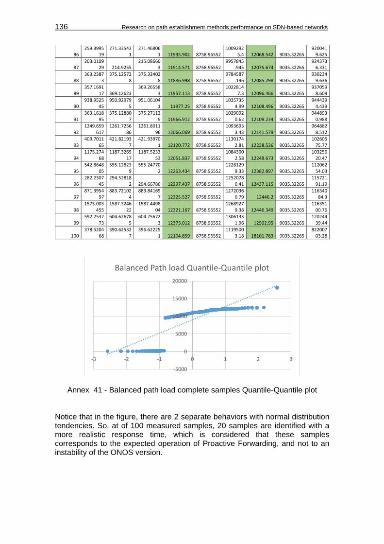
136 Research on path establishment methods performance on SDN-based networks
86 259.3995
19 271.33542
1 271.46806
1 11935.902 8758.96552 1009292
5.4 12068.542 9035.32265 920041
9.625
87 203.0109
29 214.9255 215.08660
3 11914.571 8758.96552 9957845
.945 12075.674 9035.32265 924373
6.331
88 363.2387
3 375.12572
8 375.32402
8 11886.998 8758.96552 9784587
.196 12085.298 9035.32265 930234
9.636
89 357.1691
17 369.12623 369.26558
3 11957.113 8758.96552 1022814
7.3 12096.466 9035.32265 937059
8.609
90 938.9525
45 950.92979
5 951.06104
1 11977.25 8758.96552 1035735
4.99 12108.496 9035.32265 944439
4.439
91 363.1618
95 375.12880
7 375.27112
9 11966.912 8758.96552 1029092
0.62 12109.234 9035.32265 944893
0.988
92 1249.659
617 1261.7256
86 1261.8011
96 12066.069 8758.96552 1093693
3.43 12141.579 9035.32265 964882
8.512
93 409.7011
65 421.82193
7 421.93970
1 12120.772 8758.96552 1130174
2.81 12238.536 9035.32265 102605
75.77
94 1175.274
68 1187.3265
17 1187.5233
53 12051.837 8758.96552 1084300
2.58 12248.673 9035.32265 103256
20.47
95 542.8648
05 555.12823
9 555.24770
2 12263.434 8758.96552 1228129
9.33 12382.897 9035.32265 112062
54.03
96 282.2307
45 294.52818
2 294.66786 12297.437 8758.96552 1252078
0.41 12437.115 9035.32265 115721
91.19
97 871.3954
97 883.72102
4 883.84169
7 12325.527 8758.96552 1272036
0.79 12446.2 9035.32265 116340
84.3
98 1575.003
455 1587.3246
22 1587.4498
04 12321.167 8758.96552 1268927
9.38 12446.349 9035.32265 116351
00.76
99 592.2537
73 604.62678
5 604.75672
3 12373.012 8758.96552 1306133
1.96 12502.95 9035.32265 120244
39.44
100 378.5204
68 390.62532
7 396.62225
1 12104.859 8758.96552 1119500
3.18 18101.783 9035.32265 822007
03.28
Annex 41 - Balanced path load complete samples Quantile-Quantile plot Notice that in the figure, there are 2 separate behaviors with normal distribution tendencies. So, at of 100 measured samples, 20 samples are identified with a more realistic response time, which is considered that these samples corresponds to the expected operation of Proactive Forwarding, and not to an instability of the ONOS version.
-5000
0
5000
10000
15000
20000
-3 -2 -1 0 1 2 3
Balanced Path load Quantile-Quantile plot
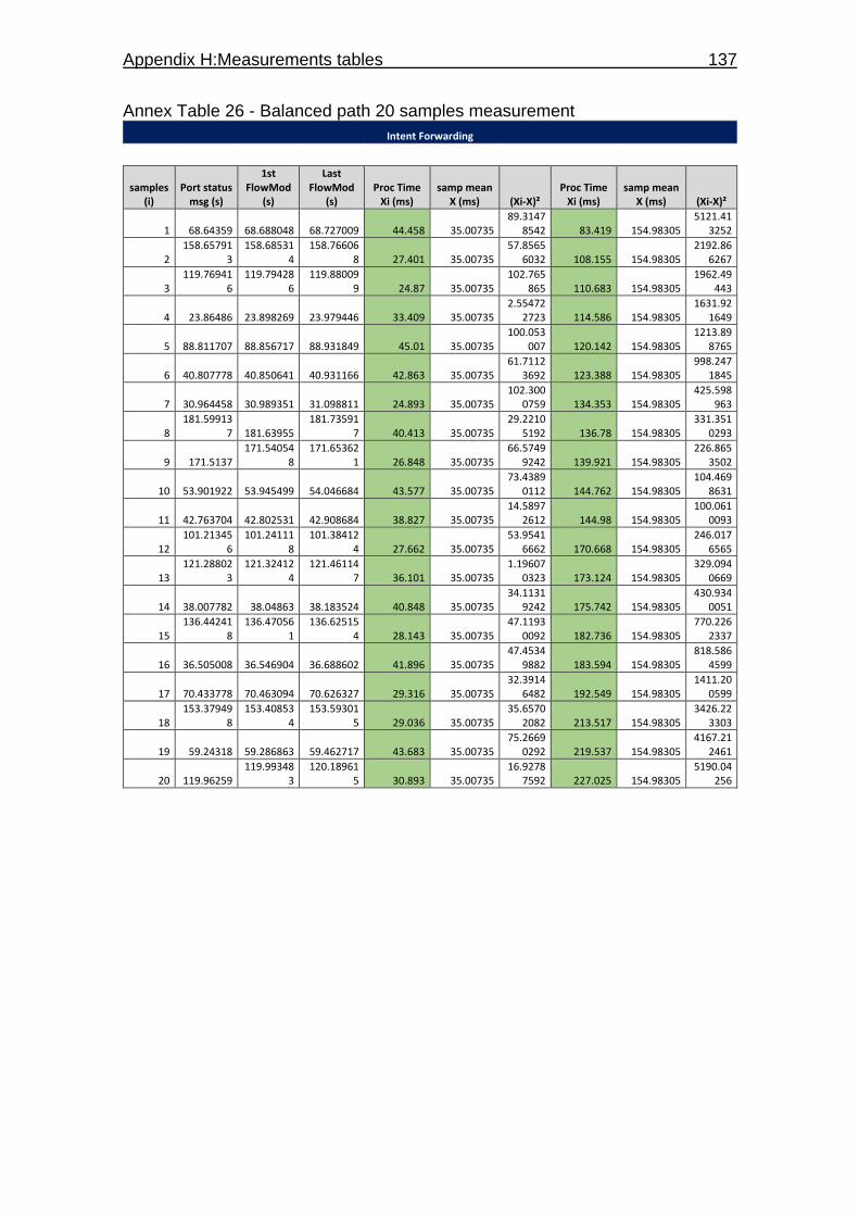
Appendix H:Measurements tables 137
Annex Table 26 - Balanced path 20 samples measurement
Intent Forwarding
samples (i)
Port status msg (s)
1st FlowMod
(s)
Last FlowMod
(s) Proc Time
Xi (ms) samp mean
X (ms) (Xi-X)² Proc Time
Xi (ms) samp mean
X (ms) (Xi-X)²
1 68.64359 68.688048 68.727009 44.458 35.00735 89.3147
8542 83.419 154.98305 5121.41
3252
2 158.65791
3 158.68531
4 158.76606
8 27.401 35.00735 57.8565
6032 108.155 154.98305 2192.86
6267
3 119.76941
6 119.79428
6 119.88009
9 24.87 35.00735 102.765
865 110.683 154.98305 1962.49
443
4 23.86486 23.898269 23.979446 33.409 35.00735 2.55472
2723 114.586 154.98305 1631.92
1649
5 88.811707 88.856717 88.931849 45.01 35.00735 100.053
007 120.142 154.98305 1213.89
8765
6 40.807778 40.850641 40.931166 42.863 35.00735 61.7112
3692 123.388 154.98305 998.247
1845
7 30.964458 30.989351 31.098811 24.893 35.00735 102.300
0759 134.353 154.98305 425.598
963
8 181.59913
7 181.63955 181.73591
7 40.413 35.00735 29.2210
5192 136.78 154.98305 331.351
0293
9 171.5137 171.54054
8 171.65362
1 26.848 35.00735 66.5749
9242 139.921 154.98305 226.865
3502
10 53.901922 53.945499 54.046684 43.577 35.00735 73.4389
0112 144.762 154.98305 104.469
8631
11 42.763704 42.802531 42.908684 38.827 35.00735 14.5897
2612 144.98 154.98305 100.061
0093
12 101.21345
6 101.24111
8 101.38412
4 27.662 35.00735 53.9541
6662 170.668 154.98305 246.017
6565
13 121.28802
3 121.32412
4 121.46114
7 36.101 35.00735 1.19607
0323 173.124 154.98305 329.094
0669
14 38.007782 38.04863 38.183524 40.848 35.00735 34.1131
9242 175.742 154.98305 430.934
0051
15 136.44241
8 136.47056
1 136.62515
4 28.143 35.00735 47.1193
0092 182.736 154.98305 770.226
2337
16 36.505008 36.546904 36.688602 41.896 35.00735 47.4534
9882 183.594 154.98305 818.586
4599
17 70.433778 70.463094 70.626327 29.316 35.00735 32.3914
6482 192.549 154.98305 1411.20
0599
18 153.37949
8 153.40853
4 153.59301
5 29.036 35.00735 35.6570
2082 213.517 154.98305 3426.22
3303
19 59.24318 59.286863 59.462717 43.683 35.00735 75.2669
0292 219.537 154.98305 4167.21
2461
20 119.96259 119.99348
3 120.18961
5 30.893 35.00735 16.9278
7592 227.025 154.98305 5190.04
256

138 Research on path establishment methods performance on SDN-based networks
Annex Table 27 – 20 sample based response confidence interval
Sum (Xi-X)² 31098.72511
Variance 1636.775006
Smp Std Dev 40.45707609
conf Level 0.95
α 0.05
DF 19
tα 2.093024054
Err Margin 18.93449445
Resp. Time (ms)
ConfInt high 173.9175445
ConfInt low 136.0485555
Annex Table 28 - 20 sample based processing confidence interval
Sum (Xi-X)² 1044.460419
Variance 54.97160098
Smp Std Dev 7.414283578
conf Level 0.95
α 0.05
DF 19
tα 2.093024054
Err Margin 3.469991528
Proc. Time (ms)
ConfInt high 38.47734153
ConfInt low 31.53735847
Annex 42 - 20 sample based Quantile-Quantile plot
0
50
100
150
200
250
-2.5 -2 -1.5 -1 -0.5 0 0.5 1 1.5 2
Quantile Quantile Plot balanced path load 20 samples PF

Appendix I:Jitel 2015 article 139
APPENDIX I: JITEL 2015 ARTICLE

Influence of the path establishment method on anSDN controller time response
David Jose Quiroz Martina, Cristina Cervello-PastorDepartment of Network Engineering,Universitat Politecnica de Catalunya,
Esteve Terradas, 7, 08860, Castelldefels, [email protected], [email protected]
Abstract—This paper aims for the assessment of a layer 3 pathestablishment method, to explore the time response added to anSoftware Defined Networking (SDN) controller during networkevents and some additional operations, measured from an SDNpath methodology used as a reference. The experience learnedin this experimentation is presented as an alternative to monitorthe processing time that new path establishment methods canbring to an SDN environment.
Index Terms—Software Defined Networking (SDN), con-trollers, control layer.
I. INTRODUCTION
Software Defined Networking (SDN) has acquired greatacceptance in the networking community. Thus, several de-velopments and advances have been made to introduce newfunctions and applications that can give more maturity andspecialized operations to the system. Some developments in-clude the adaptation of layer 3 (L3) protocols, such as IGP andBGP to support routing methods into the SDN environment.Since the principle of SDN is a centralized control of thenetwork, every operation triggered by these protocols impliesprocessing introduced to the controller and a response time,that may or may not have an impact over the network.
Keeping track of the response time during the adaptationof a new path method to SDN, can help developers settingup a margin, to fulfill a balance between the time requiredto address the processing needs of the path method, andmaintaining a lower response time from the controller.
One example of a L3 path establishment method that isbeing adapted to SDN is Segment Routing. This methodconstructs an end to end path based on a sequence of nodesand port codes called segments [1]. On the first node, a packetis guided by this sequence of segments. Once the packet passesthrough each segment, its related segment id (SID) is pulledout of the sequence. This behaviour is maintained until thepacket arrives to the edge node that connects to the destination.
This article conducts a series of measurements that helpsto determine the approximated response time that SegmentRouting can introduce into an SDN controller during normaloperations and during network events. The response times arecompared with the performance of the Proactive Forwardingmethod. This mechanism is a L2 path establishment procedure,traditionally used in SDN to construct paths according totraffic destination addresses, and set up by flows installed on
all switches relevant to the path. The response times of thismethod are used as a reference to visualize the additionaltime response introduced by Segment Routing, with respectof controller’s default state where Proactive Forwarding issupported.
Both path methods are established by the controller intothe network using the OpenFlow protocol as their interfacebetween the control plane and data plane. The actions triggeredby both methods are exchanged between the controller and thenetwork devices through OpenFlow messages.
OpenFlow has been the first protocol used in SDN as thecommunication interface between the control plane and theforwarding plane, found in network devices such as switchesand routers. It is widely used in most of the current SDN con-trollers to address the dynamic control of network resourcesaccording to the needs of today’s applications [2]. It uses TCPsessions to carry out instructions given by the SDN controller,and programs the flow tables found in different networkdevices, to set an OpenFlow pipeline where the forwardingprocess is carried out by entries found in the flow tables.
This paper will show that, according to the method applied,the actions triggered by both path methods will determine theway of how the OpenFlow pipeline will be used on the networkdevices during packet forwarding.
The remainder of this paper is organized as follows. SectionII describes the network scenario, including the test scenariosand the elements specifications. Section III illustrates thetesting process of each path mechanism and their results.Section IV is devoted to the analysis of the experimentalresults obtained in the previous section. Finally, Section Vpresents the conclusions and future work.
II. NETWORK SCENARIO DESCRIPTION
The general idea to measure the behavior of path methodsin front of network events is to provide a scenario wherean end to end communication is available through multiplepaths. A virtual network topology was built to meet theseconditions, and is presented on Fig. 1. The network topologyis comprised of 10 L2 virtual switches interconnected withan SDN controller, using a TCP port per switch-controllerconnection over a single ethernet link of 1Gbps, 2 virtualhosts (h1 and h2) from where the end to end communicationis taken place, and 12 virtual Ethernet links interconnecting
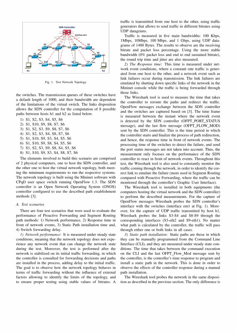
S1
S2 S4S3 S5
S6
S7S9S10
h1 h2
SDN Controller
S8
Eth1
Eth1Eth1
Eth1
Eth1
Eth1
Eth1
Eth1
Eth1
Eth2
Eth2
Eth2
Eth2 Eth2 Eth2
Eth2
Eth2
Eth2
Eth3
Eth3Eth3
Eth3
Eth3
Eth1
Eth2
Interface em1
Eth3
Fig. 1. Test Network Topology.
the switches. The transmission queues of these switches havea default length of 1000, and their bandwidth are dependentof the limitations of the virtual switch. The links dispositionallows the SDN controller for the computation of 8 possiblepaths between hosts h1 and h2 as listed below.
1) S1, S2, S3, S4, S5, S62) S1, S10, S9, S8, S7, S63) S1, S2, S3, S9, S8, S7, S64) S1, S2, S3, S4, S8, S7, S65) S1, S10, S9, S3, S4, S5, S66) S1, S10, S9, S8, S4, S5, S67) S1, S2, S3, S9, S8, S4, S5, S68) S1, S10, S9, S3, S4, S8, S7, S6The elements involved to build this scenario are comprised
of 2 physical computers, one to host the SDN controller, andthe other one to host the virtual network topology, both meet-ing the minimum requirements to run the respective systems.The network topology is built using the Mininet software withCPqD user space switch running OpenFlow 1.3. The SDNcontroller is an Open Network Operating System (ONOS)controller configured to use the described path establishmentmethods [3].
A. Test scenarios
There are four test scenarios that were used to evaluate theperformance of Proactive Forwarding and Segment Routingpath methods: 1) Network performance, 2) Response time infront of network events, 3) Static Path installation time and,4) Switch forwarding delay.
1) Network performance: It is measured under steady stateconditions, meaning that the network topology does not expe-rience any network event that can change the network stateduring the test. Moreover, the test is performed after thenetwork is stabilized on its initial traffic forwarding, in whichthe controller is consulted for forwarding decisions and pathsare installed in the process, adding delay to the initial traffic.The goal is to observe how the network topology behaves interms of traffic forwarding without the influence of externalfactors allowing to identify the limits of the topology, andto ensure proper testing using stable values of bitrates. A
traffic is transmitted from one host to the other, using trafficgenerators that allows to send traffic in different bitrates usingUDP datagrams.
Traffic is measured in five main bandwidths: 100 Kbps,1Mbps, 10Mbps, 100 Mbps, and 1 Gbps, using UDP data-grams of 1400 Bytes. The results to observe are the receivingbitrate and packet loss percentage. Using the more stablebandwidth (0% packet loss and end to end sustained bitrate),the round trip time and jitter are also measured.
2) The Response time: This time is measured under net-work event conditions, where a constant rate traffic is gener-ated from one host to the other, and a network event such aslink failures occur during transmission. The link failures areemulated by shutting down specific links of the network in theMininet console while the traffic is being forwarded throughthose links.
The Wireshark tool is used to measure the time that takesthe controller to reroute the paths and redirect the traffic.OpenFlow messages exchange between the SDN controllerand the switches are captured based on [3]. The time frameis measured between the instant where the network eventis detected by the SDN controller (OFPT PORT STATUSmessage), and the last flow message (OFPT FLOW MOD)sent by the SDN controller. This is the time period in whichthe controller starts and finalize the process of path redirection,and hence, the response time in front of network events. Theprocessing time of the switches to detect the failure, and sendthe port status messages are not taken into account. Thus, themeasurement only focuses on the performance of the SDNcontroller to react in front of network events. Throughout thistest, the Wireshark tool is also used to constantly monitor thetraffic coming through the network, in order to identify the cor-rect link to emulate the failure (more used in Segment Routingcompared with Proactive Forwarding, where the traffic can bemonitored through the controller’s Graphic User Interface).
The Wireshark tool is installed in both equipments (thecomputers hosting the virtual network and the SDN controller)to perform the described measurements. For the capture ofOpenFlow messages Wireshark probes the SDN controller’sinterface with the switches (interface em1 at Fig. 1). More-over, for the capture of UDP traffic transmitted by host h1,Wireshark probes the links S3-S4 and S8-S9 through thecorresponding interfaces (S3-eth2 and S9-eth1). No matterwhat path is calculated by the controller, the traffic will passthrough either one or both links in all cases.
3) Static path installation: Static paths are those in whichthey can be manually programmed from the Command LineInterface (CLI), and they are measured under steady state con-ditions. The time that takes between the command executionon the CLI and the last OFPT Flow Mod message sent bythe controller, is the controller’s time response to program andinstall a static path in the network. This is done in order toobserve the effects of the controller response during a manualpath installation.
The Wireshark tool probes the network in the same disposi-tion as described in the previous section. The only difference is

that in the computer hosting the SDN controller, the Wiresharkprobes not only the interface connecting to the virtual network(em1), but also to a secondary interface where it can captureinstructions sent by a remote computer (wlan0), as illustratedon Fig. 2. This remote computer is used to initiate a remoteCLI session with the controller, and send the execution ofthe path installation. Wireshark can capture the executiontimestamp, and compare it against the subsequent OpenFlowmessage time stamps, allowing to measure the time frameunder a common time reference.
4) Switch packet forwarding delay: This time is measuredunder steady state conditions. The delay observed for an IPpacket to be forwarded by a switch in the network correspondsto the time that takes this IP packet between entering an inputswitch port, and forwarded to an output switch port. This isdone in order to observe the effects of how the path methodsuse the OpenFlow Pipeline of the switches. In this case, thewireshark tool is used on switch S2, chosen randomly for thistest to probe its interfaces S2-eth1 as the input port, and S2-eth2 as the output port.
B. Elements specifications
The specifications of the involved elements in the networkscenario are the following:
• Computer hosting the SDN controller– 3.4GHz Intel(R) Core(TM) i7-3770 processor– 16GB RAM memory– 64bit Ubuntu 14.04.01
• Computer hosting the network topology– 3.4GHz Intel(R) Pentium(R) D dual core processor– 1GB RAM memory– 64bit Ubuntu 14.04.01
• ONOS Controller versions– Blackbird release 1.1.0rc2– Spring-Open
• Mininet release 2.2.0• CPqD Software switch release 1.3.0
– User-space switch– OpenFlow 1.3
• Measurement tools– Wireshark version 1.10.6– Iperf version 2.0.5
III. EVALUATION OF THE PATH METHODS
Both Proactive Forwarding and Segment Routing mech-anisms have demonstrated their capacity to sustain trafficduring network events and manual configuration of paths,despite of their differences in path processing times. Thefollowing subsections illustrate the testing process of each pathmechanism and their results.
A. Proactive Forwarding Testing
Using the network topology, Proactive Forwarding is ap-plied using the intent forwarding application of the Blackbirdversion ONOS controller [4]. Since Proactive Forwarding is
S1
S2 S4S3 S5
S6
S7S9S10
h1 h2
SDN Controller
S8Eth1
Eth2
Interface em1Remote Computer
Interface
wlan0
Fig. 2. Wireshark Probe Location.
used as a layer 2 routing mechanism, the virtual hosts (h1and h2) IP addresses are configured under the same subnet asshown in Fig. 3.
For the network performance test, Iperf was used to generatetraffic comprised of UDP datagrams within IP packets, usinga constant bitrate, and measuring on intervals of 1 secondduring 1 minute test. The average results observed in the testare illustrated on Table I.
Up to traffic of 100 Mbps there is a huge packet lossdetected on the network, and on the rates of 1 Mbps and10 Mbps, despite of not presenting packet losses, the band-width is not maintained throughout the network, which meansthat the subsequent tests have to be made under 1 Mbps rates.This is a limitation introduced by the virtual switch by notworking at kernel space, which cannot take full advantage ofthe hardware to sustain higher bandwidth.
Using the rate of 100 Kbps the values of jitter and roundtrip time (RTT) are measured to keep track of the initialconditions of the network before the subsequent tests. Theaverage round trip time observed was 1.54 ms and an averagejitter of 0.043 ms.
S1
S2 S4S3 S5
S6
S7S9S10h1 h2
SDN Controller
S8
10.0.0.2/2410.0.0.1/24
10.60.1.1:6633
Fig. 3. Proactive Forwarding Topology.

TABLE INETWORK PERFORMANCE USING PROACTIVE FORWARDING.
Bitrate Packet Loss Received Bitrate100 Kbps 0% 100 Kbps1 Mbps 0% 412 Kbps10 Mbps 0% 2.24 Mbps100 Mbps 78% 3.31 Mbps1 Gbps 96% 2.89 Mbps
For the response time testing, Iperf generates a constantrate traffic, measuring on intervals of 1 second during a timeframe of 20 seconds in which the link failure is emulated.A number of 100 measurements were made for the networkresponse, executing failures in specific links where the trafficwas passing through. Since the path computation is dynamic,not always the SDN controller computed the same initial pathon the network, but in most cases it resolved the shortest paths(1 or 2 as described in section II). The emulated failureswere links S3-S4 and S8-S9, since the traffic will alwayspass through either one or both links in every possible path.The controller always recalculates the shortest path after afailure, which in most cases were also paths 1 or 2 describedin section II. Table II shows the minimum, maximum, andaverage time of response that the controller took to process thepath redirection, and to completely install it into the network.It also shows the sample standard deviation (σ) and the 95%Confidence Interval (CI).
A time frame is measured between the first port sta-tus message received by the controller, and the firstOFPT FLOW MOD message sent by the controller to theswitches. This is the approximated time that the controllertakes to process the information received about the changeoccurred in the network topology [3]. The time between thefirst port status message and the last OFPT FLOW MODmessage, is the overall time that takes the controller to processthe topology change information, and completely install allthe necessary flows to redirect the traffic to the new path[3]. In all the measurements made, there was a minimumtraffic interruption observed (0.0012% of average packet loss)between hosts h1 and h2, with a 95% confidence that the meanjitter maintains on the range between 0.0592 ms and 0.0709ms.
In other observations made during the test of ProactiveForwarding, the paths created not always were multiple paths.In other words, the path computed by the controller, in many
TABLE IIRESPONSE TIME USING PROACTIVE FORWARDING.
Description Until First Flow Mod Until Last Flow ModMinimum 22.513 ms 28.554 msMaximum 55.978 ms 64.292 msAverage 25.226 ms 40.753 msSample σ 4.89 ms 6.178 ms95% CI 24.25 ms - 26.2 ms 39.52 ms - 41.97 ms
TABLE IIIPATH INSTALLATION TIME USING PROACTIVE FORWARDING.
Description Until Last Flow ModMinimum 27.125 msMaximum 77.752 msAverage 52.29 msSample σ 13.679 ms95% CI 49.57 ms - 55 ms
cases did not took advantage of other possible paths availablein the network, and load balance the traffic among the links.
For the static path installation measurement, a point topoint intent is manually configured on the controller usingthe ONOS built-in app ”push-test-intent” [5]. 100 intentswere emulated to measure 100 path installations, where theapp execution was made from a remote computer, and itstimestamp captured by Wireshark as earlier described in Fig. 2.The time frame between the app execution and the lastOFPT FLOW MOD message sent by the controller to theswitches, is the time response that the controller takes toprocess the intent submission and install the static path in thenetwork. Table III illustrates the minimum, maximum, andaverage path installation response time, as well as the samplestandard deviation (σ) and the 95% Confidence Interval (CI).
Packet forwarding through the switches had an averagedelay of 186.49 µs, in which the mean delay is within therange of 178.358 µs and 194.621 µs, with a confidence levelof 95%.
B. Segment Routing Testing
The implementation of this method is based on the ex-perimentation made by the Onosproject [6]. In this project,Segment Routing is used as an extension of MPLS into anSDN environment. The same ONOS version utilized for thatexperimentation (Spring-Open) is also used to conduct theseries of tests previously described in the preceding section.The ONOS controller at the network topology is used toload a configuration to the CPqD switches to emulate routingcapabilities on them. Each switch is assigned with a loopbackIP address and a Segment Routing ID (SID), to identifythem as Segment Routing nodes according to [7]. SinceSegment Routing is a L3 mechanism, each host is configuredunder different subnets. Fig. 4 illustrates the logical networktopology configured by the controller using the Mininet net-work topology. In the topology, the flows downloaded to theswitches are MPLS and IP table entries that are used by eachswitch to compute the path between hosts h1 and h2. In allthe cases, the initial routes computed were the paths 1 and 2described in section II, in which both were used during traffic.The forwarding actions are determined by group entries in thegroup table. Here group chaining is used to push SIDs of thehops involved in the path into the MPLS label stack in orderto construct the segment sequence that will route the packetthrough the network.
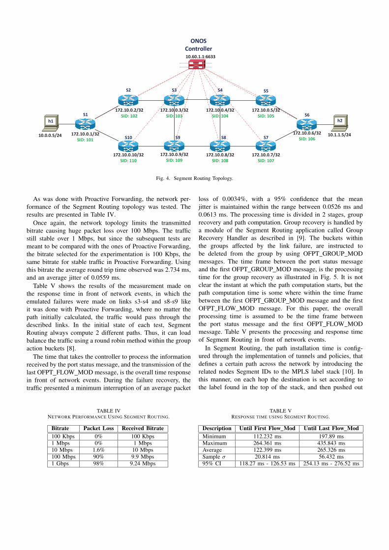
ONOS
Controller
S1 S6
h1 h2
10.0.0.5/24 10.1.1.5/24172.10.0.1/32
SID: 101
10.60.1.1:6633
S2 S3 S4 S5
S10 S9 S8 S7
172.10.0.2/32
SID: 102
172.10.0.3/32
SID: 103
172.10.0.4/32
SID: 104
172.10.0.5/32
SID: 105
172.10.0.6/32
SID: 106
172.10.0.7/32
SID: 107
172.10.0.8/32
SID: 108
172.10.0.9/32
SID: 109
172.10.0.10/32
SID: 110
Fig. 4. Segment Routing Topology.
As was done with Proactive Forwarding, the network per-formance of the Segment Routing topology was tested. Theresults are presented in Table IV.
Once again, the network topology limits the transmittedbitrate causing huge packet loss over 100 Mbps. The trafficstill stable over 1 Mbps, but since the subsequent tests aremeant to be compared with the ones of Proactive Forwarding,the bitrate selected for the experimentation is 100 Kbps, thesame bitrate for stable traffic in Proactive Forwarding. Usingthis bitrate the average round trip time observed was 2.734 ms,and an average jitter of 0.0559 ms.
Table V shows the results of the measurement made onthe response time in front of network events, in which theemulated failures were made on links s3-s4 and s8-s9 likeit was done with Proactive Forwarding, where no matter thepath initially calculated, the traffic would pass through thedescribed links. In the initial state of each test, SegmentRouting always compute 2 different paths. Thus, it can loadbalance the traffic using a round robin method within the groupaction buckets [8].
The time that takes the controller to process the informationreceived by the port status message, and the transmission of thelast OFPT FLOW MOD message, is the overall time responsein front of network events. During the failure recovery, thetraffic presented a minimum interruption of an average packet
TABLE IVNETWORK PERFORMANCE USING SEGMENT ROUTING.
Bitrate Packet Loss Received Bitrate100 Kbps 0% 100 Kbps1 Mbps 0% 1 Mbps10 Mbps 1.6% 10 Mbps100 Mbps 90% 9.9 Mbps1 Gbps 98% 9.24 Mbps
loss of 0.0034%, with a 95% confidence that the meanjitter is maintained within the range between 0.0526 ms and0.0613 ms. The processing time is divided in 2 stages, grouprecovery and path computation. Group recovery is handled bya module of the Segment Routing application called GroupRecovery Handler as described in [9]. The buckets withinthe groups affected by the link failure, are instructed tobe deleted from the group by using OFPT GROUP MODmessages. The time frame between the port status messageand the first OFPT GROUP MOD message, is the processingtime for the group recovery as illustrated in Fig. 5. It is notclear the instant at which the path computation starts, but thepath computation time is some where within the time framebetween the first OFPT GROUP MOD message and the firstOFPT FLOW MOD message. For this paper, the overallprocessing time is assumed to be the time frame betweenthe port status message and the first OFPT FLOW MODmessage. Table V presents the processing and response timeof Segment Routing in front of network events.
In Segment Routing, the path installation time is config-ured through the implementation of tunnels and policies, thatdefines a certain path across the network by introducing therelated nodes Segment IDs to the MPLS label stack [10]. Inthis manner, on each hop the destination is set according tothe label found in the top of the stack, and then pushed out
TABLE VRESPONSE TIME USING SEGMENT ROUTING.
Description Until First Flow Mod Until Last Flow ModMinimum 112.232 ms 197.89 msMaximum 264.361 ms 435.843 msAverage 122.399 ms 265.326 msSample σ 20.814 ms 56.432 ms95% CI 118.27 ms - 126.53 ms 254.13 ms - 276.52 ms

Fig. 5. Segment Routing link recovery process time frame.
at each hop until it reaches the edge node that is connectedto the destination network. In this implementation of SegmentRouting brought by the ONOS project, the configuration oftunnels represent the arrange of SIDs, which would be thegroup numbers that would be joined into a group chain.At this point, when the tunnel configuration is executedfrom the console, the controller processes the creation of thenecessary groups and add them to the switches group tables byusing OFPT GROUP MOD messages. On the other hand, theconfiguration of policies represents the information of sourceand destination addresses, the destination group to execute thepolicy, and the priority that the path would have. When thepolicies are executed from the console, the controller processesthe information into Access Lists (ACL) that are downloadedto the switches by using OFPT FLOW MOD messages. Fig. 6displays the time frame of these processes.
Since the tunnel and policy configurations are separateexecutions, the measurement cannot be assumed as thecomplete time frame from the first execution to the lastOFPT FLOW MOD message, because it would introduceadditional delay that is not relevant to the processing time ofthe controller. In other words, the measurement of the overalltime response for the static path installation would be:
RT = TCT + PCT, (1)
where RT is the response time of the path installation,TCT is the tunnel configuration time, and PCT the policyconfiguration time.
Table VI illustrates the times measured for the manuallyinstalled paths. The measurements presents a sample standard
Fig. 6. Segment Routing static path installation time frame.
TABLE VIPATH INSTALLATION TIME USING SEGMENT ROUTING.
Description Tunnel Policy Path InstallationMinimum 3.42 ms 1.951 ms 5.371 msMaximum 9.625 ms 7.104 ms 16.729 msAverage 7.761 ms 3.69 ms 11.452 ms
deviation (σ) of 2.488 ms, with a 95% confidence that themean response time is maintained within the range between10.959 ms and 11.946 ms. Compared with the network eventtest, the response time is lower, due to the operation that takesplace in the process. Thus, it only comprises an installation ofan Access List (ACL) entry in the Access List table (ACLtable) and the insertion of additional groups in the grouptable, without modifying the entire group table on the relatedswitches.
The average packet forwarding delay observed on the switchwas 290.2 µs and a sample standard deviation of 37.311 µs,with 95% confidence that the mean delay is within the rangebetween 282.796 µs and 297.603 µs. Compared to the testmade on Proactive Forwarding, Segment Routing introducesmore delay in the switch for packet forwarding.
IV. RESULTS ANALYSIS
The measurements performed are reviewed and analysed onFig. 7 comparing the results of both mechanism working onthe network topology previously described.
There is a clear difference in time response, in whichSegment Routing presents more delay in most of the mea-surements. The switch forwarding delay shows the effects ofOpenFlow Pipeline usage introduced by both mechanisms.
On one hand, in Proactive Forwarding, the pipeline process-ing used is the standard method of OpenFlow as described in[8]. In this procedure, each ingress packet start a lookup foran entry in the first flow table (table 0). It can go to a nextflow table or forwarded to an egress port, or to the controller,depending on the action set found in the matched flow entry.In the case of our topology, only one flow table was created
25.23
40.75
52.29
0.186
122.40
265.33
11.45
0.29
0.10 1.00 10.00 100.00 1000.00
Controller Processing Time
Network Event Response Time
Manual Path Installation Time
Switch Forwarding Delay
Segment Routing Proactive Forwarding
Time (ms)
Fig. 7. Test Results Comparison.
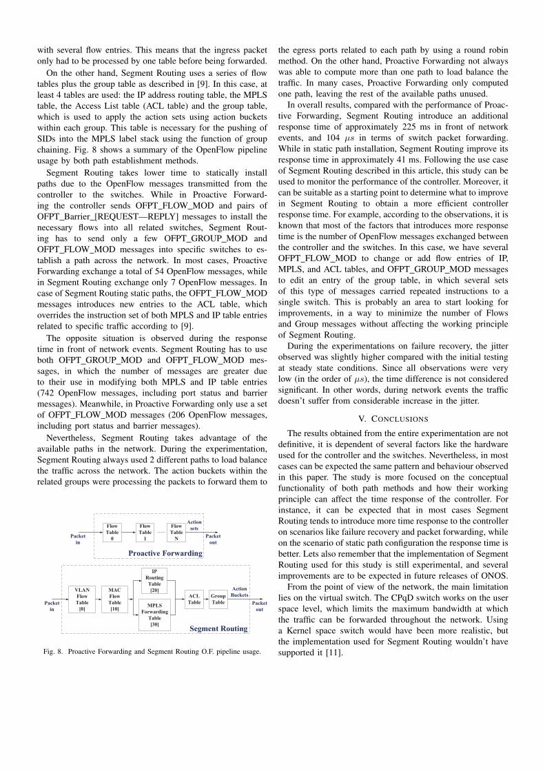
with several flow entries. This means that the ingress packetonly had to be processed by one table before being forwarded.
On the other hand, Segment Routing uses a series of flowtables plus the group table as described in [9]. In this case, atleast 4 tables are used: the IP address routing table, the MPLStable, the Access List table (ACL table) and the group table,which is used to apply the action sets using action bucketswithin each group. This table is necessary for the pushing ofSIDs into the MPLS label stack using the function of groupchaining. Fig. 8 shows a summary of the OpenFlow pipelineusage by both path establishment methods.
Segment Routing takes lower time to statically installpaths due to the OpenFlow messages transmitted from thecontroller to the switches. While in Proactive Forward-ing the controller sends OFPT FLOW MOD and pairs ofOFPT Barrier [REQUEST—REPLY] messages to install thenecessary flows into all related switches, Segment Rout-ing has to send only a few OFPT GROUP MOD andOFPT FLOW MOD messages into specific switches to es-tablish a path across the network. In most cases, ProactiveForwarding exchange a total of 54 OpenFlow messages, whilein Segment Routing exchange only 7 OpenFlow messages. Incase of Segment Routing static paths, the OFPT FLOW MODmessages introduces new entries to the ACL table, whichoverrides the instruction set of both MPLS and IP table entriesrelated to specific traffic according to [9].
The opposite situation is observed during the responsetime in front of network events. Segment Routing has to useboth OFPT GROUP MOD and OFPT FLOW MOD mes-sages, in which the number of messages are greater dueto their use in modifying both MPLS and IP table entries(742 OpenFlow messages, including port status and barriermessages). Meanwhile, in Proactive Forwarding only use a setof OFPT FLOW MOD messages (206 OpenFlow messages,including port status and barrier messages).
Nevertheless, Segment Routing takes advantage of theavailable paths in the network. During the experimentation,Segment Routing always used 2 different paths to load balancethe traffic across the network. The action buckets within therelated groups were processing the packets to forward them to
Flow
Table
N
Proactive Forwarding
Packet
in
Flow
Table
1
Flow
Table
0
MPLS
Forwarding
Table
[30]
ACL
Table
Group
Table
Segment Routing
Packet
in
Packet
out
IP
Routing
Table
[20]MAC
Flow
Table
[10]
VLAN
Flow
Table
[0]
Packet
out
Action
sets
Action
Buckets
Fig. 8. Proactive Forwarding and Segment Routing O.F. pipeline usage.
the egress ports related to each path by using a round robinmethod. On the other hand, Proactive Forwarding not alwayswas able to compute more than one path to load balance thetraffic. In many cases, Proactive Forwarding only computedone path, leaving the rest of the available paths unused.
In overall results, compared with the performance of Proac-tive Forwarding, Segment Routing introduce an additionalresponse time of approximately 225 ms in front of networkevents, and 104 µs in terms of switch packet forwarding.While in static path installation, Segment Routing improve itsresponse time in approximately 41 ms. Following the use caseof Segment Routing described in this article, this study can beused to monitor the performance of the controller. Moreover, itcan be suitable as a starting point to determine what to improvein Segment Routing to obtain a more efficient controllerresponse time. For example, according to the observations, it isknown that most of the factors that introduces more responsetime is the number of OpenFlow messages exchanged betweenthe controller and the switches. In this case, we have severalOFPT FLOW MOD to change or add flow entries of IP,MPLS, and ACL tables, and OFPT GROUP MOD messagesto edit an entry of the group table, in which several setsof this type of messages carried repeated instructions to asingle switch. This is probably an area to start looking forimprovements, in a way to minimize the number of Flowsand Group messages without affecting the working principleof Segment Routing.
During the experimentations on failure recovery, the jitterobserved was slightly higher compared with the initial testingat steady state conditions. Since all observations were verylow (in the order of µs), the time difference is not consideredsignificant. In other words, during network events the trafficdoesn’t suffer from considerable increase in the jitter.
V. CONCLUSIONS
The results obtained from the entire experimentation are notdefinitive, it is dependent of several factors like the hardwareused for the controller and the switches. Nevertheless, in mostcases can be expected the same pattern and behaviour observedin this paper. The study is more focused on the conceptualfunctionality of both path methods and how their workingprinciple can affect the time response of the controller. Forinstance, it can be expected that in most cases SegmentRouting tends to introduce more time response to the controlleron scenarios like failure recovery and packet forwarding, whileon the scenario of static path configuration the response time isbetter. Lets also remember that the implementation of SegmentRouting used for this study is still experimental, and severalimprovements are to be expected in future releases of ONOS.
From the point of view of the network, the main limitationlies on the virtual switch. The CPqD switch works on the userspace level, which limits the maximum bandwidth at whichthe traffic can be forwarded throughout the network. Usinga Kernel space switch would have been more realistic, butthe implementation used for Segment Routing wouldn’t havesupported it [11].

Path establishment methods introduce delay to an SDN con-troller in handling operations related to topology changes, andpath configurations, plus an added delay to OpenFlow switchesin packet handling. The awareness of these parameters can beused as a guide for performance testing in order to keep trackof the time response introduced, and look forward to maintainthe desired performance according to the needs established byoperators and standards.
The set of tests presented in this paper can be used as astarting point to observe the performance of path establishmentmethods, their behavior into an SDN environment, and toidentify initial needs for improvement that opens the door forfurther investigation of the tested technologies.
ACKNOWLEDGMENTS
This work has been supported by the Ministerio deEconomıa y Competitividad of the Spanish Government underproject TEC2013-47960-C4-1-P.
REFERENCES
[1] D. C. Frost, B. F. Stewart and C. Filsfils. United States of AmericaPatent US2014/0098675, 2014.
[2] “OpenFlow,” [Online]. Available on May 18th, 2015:https://www.opennetworking.org/sdn-resources/openflow.
[3] P. Berde, M. Gerola, J. Hart, Y. Higuchi, M. Kobayashi, T. Koide, B.Lantz, B. O’Connor, P. Radoslavov, W. Snow and G. Parulkar, “ONOS:Towards an Open, Distributed SDN OS,” [Online]. Available on May18th, 2015:http://www-cs-students.stanford.edu/∼rlantz/papers/onos-hotsdn.pdf.
[4] A. Koshibe, “Intent Framework,” 2015. [Online]. Available on May18th, 2015:https://wiki.onosproject.org/display/ONOS/Intent+Framework.
[5] S. Zhang, C. Franke, “Experiment C Plan - Intent Install/Remove/Re-route Latency,” 2015. [Online]. Available on Jul 10th, 2015:https://wiki.onosproject.org/pages/viewpage.action?pageId=3441828.
[6] S. Das, “Project Description,” 2014. [Online]. Available on May 18th,2015:https://wiki.onosproject.org/display/ONOS/Project+Description.
[7] S. Das, “Configuring ONOS (spring-open),” [Online]. Available on May18th, 2015:https://wiki.onosproject.org/pages/viewpage.action?pageId=2130918.
[8] “OpenFlow Switch Specification Version 1.3.4,” 2014. [Online].Available on May 18th, 2015:https://www.opennetworking.org/images/stories/downloads/sdn-resources/onf-specifications/openflow/openflow-spec-v1.3.0.pdf.
[9] S. Das, “Software Architecture,” 2014. [Online]. Available on May 18th,2015:https://wiki.onosproject.org/display/ONOS/Software+Architecture.
[10] S. Das, “Using the CLI,” 2014. [Online]. Available on May 18th, 2015:https://wiki.onosproject.org/display/ONOS/Using+the+CLI.
[11] S. Das, “Installation Guide,” 2014. [Online]. Available on Jul 10th,2015:https://wiki.onosproject.org/display/ONOS/Installation+Guide.
Related Documents