MARCH 2005 VOLUME 20 NUMBER 1 ITCNE4 (ISSN 0885-8969) ELECTRIC MACHINERY Fault Analysis of a PM Brushless DC Motor Using Finite Element Method ..... .... M. Dai, A. Keyhani, and T. Sebastian 1 Effects of Instantaneous Power-Supply Failure on the Operation of Slip-Energy Recovery Drives ................. ............................................................ I. Çadirci, G. Akçam, and M. Ermis 7 Parameter Identification of Induction Motors Using Dynamic Encoding Algorithm for Searches (DEAS) ............ .................................................................... J.-W. Kim and S. W. Kim 16 Thermal Modeling of Lundell Alternators ............... .............. S. C. Tang, T. A. Keim, and D. J. Perreault 25 Force Density Limits in Low-Speed Permanent-Magnet Machines Due to Saturation .......................... ........................................................ P. Kasinathan, A. Grauers, and E. Hamdi 37 Decoupled Control of Rotor Torque and Rotor Electric Power Delivered in a Salient-Pole, Synchronous Machine ..... ................................................... M. I. Masoud, J. E. Fletcher, and B. W. Williams 45 Speed Ripple Minimization in PM Synchronous Motor Using Iterative Learning Control ....................... ............................................................. W. Qian, S. K. Panda, and J. X. Xu 53 Analysis and Design of a Two-Speed Single-Phase Induction Motor With 2 and 18 Pole Special Windings .......... .................................... M. Popescu, D. M. Ionel, S. Dellinger, T. J. E. Miller, and M. McGilp 62 Application of Bi-State Magnetic Material to an Automotive IPM Starter/Alternator Machine .................... .............................................................. A. M. EL-Refaie and T. M. Jahns 71 Development of a Thermofluid Model for Axial Field Permanent-Magnet Machines ........................... ...................................................... R.-J. Wang, M. J. Kamper, and R. T. Dobson 80 Methods for Determining the Intermediate-Axis Saturation Characteristics of Salient-Pole Synchronous Machines From the Measured -Axis Characteristics.................... .................... A. M. El-Serafi and N. C. Kar 88 Turbogenerator End-Winding Leakage Inductance Calculation Using a 3-D Analytical Approach Based on the Solution of Neumann Integrals .......................... ......................... D. Ban, D. ˇ Zarko, and I. Mandic ´ 98 A Review of Stator Fault Monitoring Techniques of Induction Motors ...... ..... A. Siddique, G. S. Yadava, and B. Singh 106 An Observer-Based Robust Adaptive Controller for Permanent Magnet Synchronous Motor Drive With Initial Rotor Angle Uncertainty ....................... ........................ X. Yue, D. M. Vilathgamuwa, and K.-J. Tseng 115 Minimization of Iron Losses of Permanent Magnet Synchronous Machines .... .... C. C. Mi, G. R. Slemon, and R. Bonert 121 (Contents Continued on Back Cover)

Welcome message from author
This document is posted to help you gain knowledge. Please leave a comment to let me know what you think about it! Share it to your friends and learn new things together.
Transcript
MARCH 2005 VOLUME 20 NUMBER 1 ITCNE4 (ISSN 0885-8969)
ELECTRIC MACHINERY
Fault Analysis of a PM Brushless DC Motor Using Finite Element Method . . . . .. . . . M. Dai, A. Keyhani, and T. Sebastian 1Effects of Instantaneous Power-Supply Failure on the Operation of Slip-Energy Recovery Drives . . . . . . . . . . . . . . . . .
. . . . . . . . . . . . . . . . . . . . . . . . . . . . . . . . . . . . . . . . . . . . . . . . . . . . . . . . . . . . I. Çadirci, G. Akçam, and M. Ermis 7Parameter Identification of Induction Motors Using Dynamic Encoding Algorithm for Searches (DEAS). . . . . . . . . . . .
. . . . . . . . . . . . . . . . . . . . . . . . . . . . . . . . . . . . . . . . . . . . . . . . . . . . . . . . . . . . . . . . . . . . J.-W. Kim and S. W. Kim 16Thermal Modeling of Lundell Alternators . . . . . . . . . . . . . . .. . . . . . . . . . . . . . S. C. Tang, T. A. Keim, and D. J. Perreault 25Force Density Limits in Low-Speed Permanent-Magnet Machines Due to Saturation . . . . . . . . . . . . . . . . . . . . . . . . . .
. . . . . . . . . . . . . . . . . . . . . . . . . . . . . . . . . . . . . . . . . . . . . . . . . . . . . . . . P. Kasinathan, A. Grauers, and E. Hamdi 37Decoupled Control of Rotor Torque and Rotor Electric Power Delivered in a Salient-Pole, Synchronous Machine . . . . .
. . . . . . . . . . . . . . . . . . . . . . . . . . . . . . . . . . . . . . . . . . . . . . . . . . . M. I. Masoud, J. E. Fletcher, and B. W. Williams 45Speed Ripple Minimization in PM Synchronous Motor Using Iterative Learning Control . . . . . . . . . . . . . . . . . . . . . . .
. . . . . . . . . . . . . . . . . . . . . . . . . . . . . . . . . . . . . . . . . . . . . . . . . . . . . . . . . . . . . W. Qian, S. K. Panda, and J. X. Xu 53Analysis and Design of a Two-Speed Single-Phase Induction Motor With 2 and 18 Pole Special Windings . . . . . . . . . .
. . . . . . . . . . . . . . . . . . . . . . . . . . . . . . . . . . . . M. Popescu, D. M. Ionel, S. Dellinger, T. J. E. Miller, and M. McGilp 62Application of Bi-State Magnetic Material to an Automotive IPM Starter/Alternator Machine . . . . . . . . . . . . . . . . . . . .
. . . . . . . . . . . . . . . . . . . . . . . . . . . . . . . . . . . . . . . . . . . . . . . . . . . . . . . . . . . . . . A. M. EL-Refaie and T. M. Jahns 71Development of a Thermofluid Model for Axial Field Permanent-Magnet Machines. . . . . . . . . . . . . . . . . . . . . . . . . . .
. . . . . . . . . . . . . . . . . . . . . . . . . . . . . . . . . . . . . . . . . . . . . . . . . . . . . . R.-J. Wang, M. J. Kamper, and R. T. Dobson 80Methods for Determining the Intermediate-Axis Saturation Characteristics of Salient-Pole Synchronous Machines From
the Measured -Axis Characteristics. . . . . . . . . . . . . . . . . . . .. . . . . . . . . . . . . . . . . . . . A. M. El-Serafi and N. C. Kar 88Turbogenerator End-Winding Leakage Inductance Calculation Using a 3-D Analytical Approach Based on the Solution of
Neumann Integrals . . . . . . . . . . . . . . . . . . . . . . . . . .. . . . . . . . . . . . . . . . . . . . . . . . . D. Ban, D. Zarko, and I. Mandic 98A Review of Stator Fault Monitoring Techniques of Induction Motors . . . . . .. . . . . A. Siddique, G. S. Yadava, and B. Singh 106An Observer-Based Robust Adaptive Controller for Permanent Magnet Synchronous Motor Drive With Initial Rotor Angle
Uncertainty . . . . . . . . . . . . . . . . . . . . . . .. . . . . . . . . . . . . . . . . . . . . . . . X. Yue, D. M. Vilathgamuwa, and K.-J. Tseng 115Minimization of Iron Losses of Permanent Magnet Synchronous Machines . . . .. . . . C. C. Mi, G. R. Slemon, and R. Bonert 121
(Contents Continued on Back Cover)
(Contents Continued from Front Cover)
Improved Transient Simulation of Salient-Pole Synchronous Generators with Internal and Ground Faults in the StatorWinding . . . . . . . . . . . . . . . . . . . . . . .. . . . . . . . . . . . . . . . . . . . . . .D. Bi, X. Wang, W. Wang, Z. Q. Zhu, and D. Howe 128
Broken Rotor Bar Detection in Induction Machines With Transient Operating Speeds. . . . . . . . . . . . . . . . . . . . . . . . . .. . . . . . . . . . . . . . . . . . . . . . . . . . . . . . . . . . . . . . . . . . . . . . . . . . . . . . . . . H. Douglas, P. Pillay, and A. K. Ziarani 135
Asynchronous Performance Analysis of a Single-Phase Capacitor-Start, Capacitor-Run Permanent Magnet Motor . . . . .. . . . . . . . . . . . . . . . . . . . . . . M. Popescu, T. J. E. Miller, M. McGilp, G. Strappazzon, N. Trivillin, and R. Santarossa 142
Simple Expressions for Optimal Current Waveforms for Permanent-Magnet Synchronous Machine Drives . . . . . . . . . .. . . . . . . . . . . . . . . . . . . . . . . . . . . . . . . . . . . . . . . . . . . . . . . . . . . . . . . . . . . . . . . . . .A. P. Wu and P. L. Chapman 151
Influence of Generator Load Conditions on Third-Harmonic Voltages in Generator Stator Winding . . . . . . . . . . . . . . . .. . . . . . . . . . . . . . . . . . . . . . . . . . . . . . . . . . . . . . . . . . . . . . . . . . . . . . . . . . . . . . . M. Fulczyk and R. Mydlikowski 158
A Sophisticated Maximum Capacity Analysis for Large Turbine Generators Considering Limitation of Temperature. . . .. . . . . . . . . . . . . . . . . . . . . . . . . . . . . . . . . . . . . . . . .K. Ide, K. Hattori, K. Takahashi, K. Kobashi, and T. Watanabe 166
A New Induction Motor Drive Based on the Flux Vector Acceleration Method . . . . .. . . . . D. M. Stojic and S. N. Vukosavic 173Switching Time Model Updating for the Real-Time Simulation of Power-Electronic Circuits and Motor Drives . . . . . . .
. . . . . . . . . . . . . . . . . . . . . . . . . . . . . . . . . . . . . . . . . . . . . . . . . .B. De Kelper, H. F. Blanchette, and L.-A. Dessaint 181Optimization of Single-Phase Induction Motors—Part I: Maximum Energy Efficiency Control . . . . . . . . . . . . . . . . . . .
. . . . . . . . . . . . . . . . . . . . . . . . . . . . . . . . . . . . . . . . . . . . . . . . . . .C. Mademlis, I. Kioskeridis, and T. Theodoulidis 187Optimization of Single-Phase Induction Motors—Part II: Magnetic and Torque Performance Under Optimal Control. . . .
. . . . . . . . . . . . . . . . . . . . . . . . . . . . . . . . . . . . . . . . . . . . . . . . . . .C. Mademlis, T. Theodoulidis, and I. Kioskeridis 196
ENERGY DEVELOPMENT AND POWER GENERATION
Nonlinear Coordinated Control of Drum Boiler Power Unit Based on Feedback Linearization. . . . . . . . . . . . . . . . . . . .. . . . . . . . . . . . . . . . . . . . . . . . . . . . . . . . . . . . . . . . . . . . . . . . . . . . . . . . . . . . . . . . . . . Y. Daren and X. Zhiqiang 204
Sensitivity Analysis of the Modeling Parameters Used in Simulation of Proton Exchange Membrane Fuel Cells. . . . . . .. . . . . . . . . . . . . . . . . . . . . . . . . . . . . . . . . . . . . . . . . . . . .J. M. Corrêa, F. A. Farret, V. A. Popov, and M. G. Simões 211
Multiphysics Simulation of Wave Energy to Electric Energy Conversion by Permanent Magnet Linear Generator. . . . . .. . . . . . . . . . . . . M. Leijon, H. Bernhoff, O. Ågren, J. Isberg, J. Sundberg, M. Berg, K. E. Karlsson, and A. Wolfbrandt 219
Incorporating Well-Being Considerations in Generating Systems Using Energy Storage . . . . .. . . . . Bagen and R. Billinton 225Optimal Planning of Generating Units Over Micro-Hydro Resources Within a Catchment Area. . . . . . . . .. . . . . . . . S. Roy 231Nonlinear Identification and Control of a Turbogenerator—An On-Line Scheduled Multiple Model/Controller Approach
. . . . . . . . . . . . . . . . . . . . . . . . . . . . . . . .. . . . . . . . . . . . . . . . . . . . . . . . . . . . . . . . L. Ren, G. W. Irwin, and D. Flynn 237
POWER ENGINEERING LETTERS
Diagnosis of Stator Short Circuits in Brushless DC Motors by Monitoring Phase Voltages . . . . . . . . . . . . . . . . . . . . . .. . . . . . . . . . . . . . . . . . . . . . . . . . . . . . . . . . . . . . . . . . . . . . . . . . . . . . . . . . . . M. A. Awadallah and M. M. Morcos 246
IEEE COPYRIGHT FORM . . . . . . . . . . . . . . . . . . . . . . . . . . . . . . . . . . . . .. . . . . . . . . . . . . . . . . . . . . . . . . . . . . . . . . . . . . 251
80 IEEE TRANSACTIONS ON ENERGY CONVERSION, VOL. 20, NO. 1, MARCH 2005
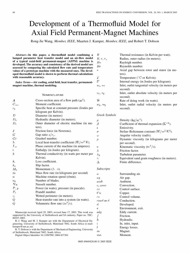
Development of a Thermofluid Model forAxial Field Permanent-Magnet MachinesRong-Jie Wang, Member, IEEE, Maarten J. Kamper, Member, IEEE, and Robert T. Dobson
Abstract—In this paper, a thermofluid model combining alumped parameter heat transfer model and an air-flow modelof a typical axial-field permanent-magnet (AFPM) machine isdeveloped. The accuracy and consistency of the derived model areassessed by comparing the calculated flow rate and temperaturevalues of a prototype machine with the measured ones. The devel-oped thermofluid model is shown to perform thermal calculationswith reasonable accuracy.
Index Terms—Air cooling, axial field, heat transfer, permanent-magnet machine, thermal modeling.
NOMENCLATURE
Cross-section area of a flow path ( ).Moment coefficient.Specific heat at constant pressure (Joules perkilogram per Kelvin).Diameter (in meters)Hydraulic diameter (in meters).Outer diameter of electric machine (in me-ters).Friction force (in Newtons).Gap ratio .Grashof number.Local heat-transfer coefficient ( ).Phase current of the machine (in amperes).Enthalpy (in Joules per kilogram).Thermal conductivity (in watts per meter perKelvin).Loss coefficient.Slip factor.Momentum ( ).Mass flow rate (in kilograms per second)Machine rotation speed (r/min).Number of blades.Nusselt number.
, Power (in watts), pressure (in pascals).Prandtl number.Wetted perimeter (in meters).Heat-transfer rate into a system (in watts).Volumetric flow rate ( ).
Manuscript received April 29, 2003; revised June 17, 2003. This work wassupported by the University of Stellenbosch and SA industry. Paper no. TEC-00107-2003.
R.-J. Wang and M. J. Kamper are with the Department of Electrical En-gineering, University of Stellenbosch, Matieland 7602, South Africa (e-mail:[email protected]).
R. T. Dobson is with the Department of Mechanical Engineering, Universityof Stellenbosch, Matieland 7602, South Africa.
Digital Object Identifier 10.1109/TEC.2004.837301
Thermal resistance (in Kelvin per watt)., , Radius, outer radius (in meters).
Rayleigh number.Reynolds number.Axial gap between rotor and stator (in me-ters).Temperature ( or Kelvin).Internal energy (in Joules per kilogram).
, Inlet, outlet tangential velocity (in meters persecond).
, Inlet, outlet absolute velocity (in meters persecond).Rate of doing work (in watts).
, Inlet, outlet radial velocity (in meters persecond).
Greek Symbols
Density ( ).Coefficient of thermal expansion ( ).Emissivity.Stefan–Boltzmann constant ( ).Angular velocity (rad/s).Dynamic viscosity (in kilograms per meterper second).Kinematic viscosity ( ).Friction factor.Turbulent parameter.Equivalent sand grain roughness (in meters).Finite difference.
Subscripts
Surrounding air.Air gap.Ambient.
, Convection.Control surface.Copper.Control volume.
or Conduction.Developed.Environment, exit.Eddy current.Friction.Hydraulic.In, inlet, input.Energy losses.Magnet.Moment.
0885-8969/$20.00 © 2005 IEEE
WANG et al.: DEVELOPMENT OF A THERMOFLUID MODEL FOR AXIAL FIELD PM MACHINES 81
Output.Periphery.Radiation, rotor.Turbulent.Total.Windage and friction.
I. INTRODUCTION
THE advent of new high-energy product permanent-magnet(PM) materials has opened up great opportunities for novel
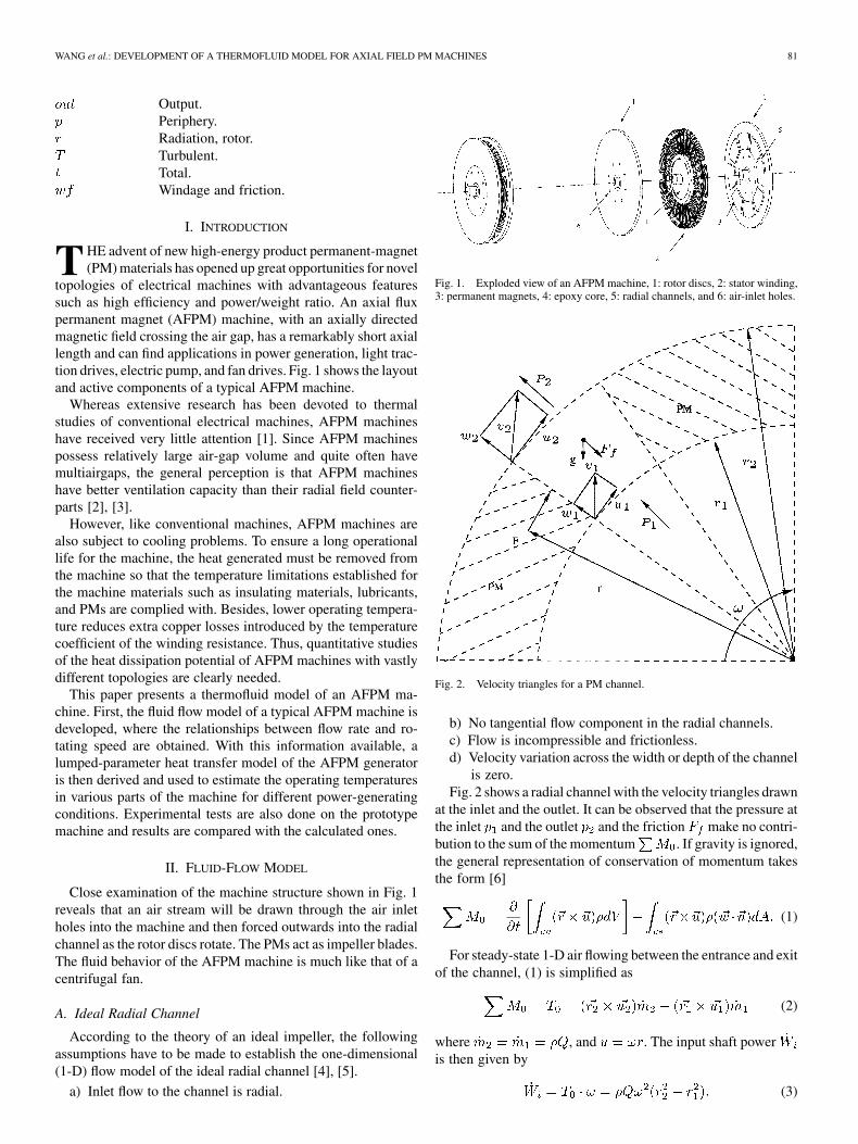
topologies of electrical machines with advantageous featuressuch as high efficiency and power/weight ratio. An axial fluxpermanent magnet (AFPM) machine, with an axially directedmagnetic field crossing the air gap, has a remarkably short axiallength and can find applications in power generation, light trac-tion drives, electric pump, and fan drives. Fig. 1 shows the layoutand active components of a typical AFPM machine.
Whereas extensive research has been devoted to thermalstudies of conventional electrical machines, AFPM machineshave received very little attention [1]. Since AFPM machinespossess relatively large air-gap volume and quite often havemultiairgaps, the general perception is that AFPM machineshave better ventilation capacity than their radial field counter-parts [2], [3].
However, like conventional machines, AFPM machines arealso subject to cooling problems. To ensure a long operationallife for the machine, the heat generated must be removed fromthe machine so that the temperature limitations established forthe machine materials such as insulating materials, lubricants,and PMs are complied with. Besides, lower operating tempera-ture reduces extra copper losses introduced by the temperaturecoefficient of the winding resistance. Thus, quantitative studiesof the heat dissipation potential of AFPM machines with vastlydifferent topologies are clearly needed.
This paper presents a thermofluid model of an AFPM ma-chine. First, the fluid flow model of a typical AFPM machine isdeveloped, where the relationships between flow rate and ro-tating speed are obtained. With this information available, alumped-parameter heat transfer model of the AFPM generatoris then derived and used to estimate the operating temperaturesin various parts of the machine for different power-generatingconditions. Experimental tests are also done on the prototypemachine and results are compared with the calculated ones.
II. FLUID-FLOW MODEL
Close examination of the machine structure shown in Fig. 1reveals that an air stream will be drawn through the air inletholes into the machine and then forced outwards into the radialchannel as the rotor discs rotate. The PMs act as impeller blades.The fluid behavior of the AFPM machine is much like that of acentrifugal fan.
A. Ideal Radial Channel
According to the theory of an ideal impeller, the followingassumptions have to be made to establish the one-dimensional(1-D) flow model of the ideal radial channel [4], [5].
a) Inlet flow to the channel is radial.
Fig. 1. Exploded view of an AFPM machine, 1: rotor discs, 2: stator winding,3: permanent magnets, 4: epoxy core, 5: radial channels, and 6: air-inlet holes.
Fig. 2. Velocity triangles for a PM channel.
b) No tangential flow component in the radial channels.c) Flow is incompressible and frictionless.d) Velocity variation across the width or depth of the channel
is zero.Fig. 2 shows a radial channel with the velocity triangles drawn
at the inlet and the outlet. It can be observed that the pressure atthe inlet and the outlet and the friction make no contri-bution to the sum of the momentum . If gravity is ignored,the general representation of conservation of momentum takesthe form [6]
(1)
For steady-state 1-D air flowing between the entrance and exitof the channel, (1) is simplified as
(2)
where , and . The input shaft poweris then given by
(3)
82 IEEE TRANSACTIONS ON ENERGY CONVERSION, VOL. 20, NO. 1, MARCH 2005
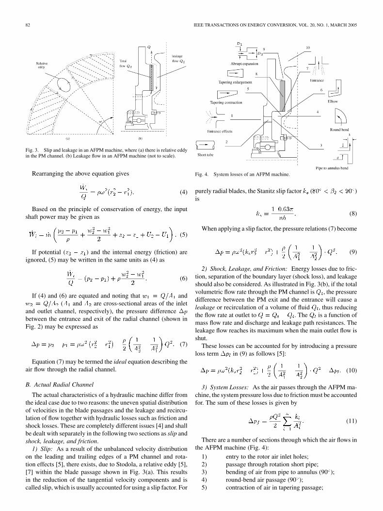
Fig. 3. Slip and leakage in an AFPM machine, where (a) there is relative eddyin the PM channel. (b) Leakage flow in an AFPM machine (not to scale).
Rearranging the above equation gives
(4)
Based on the principle of conservation of energy, the inputshaft power may be given as
(5)
If potential ( ) and the internal energy (friction) areignored, (5) may be written in the same units as (4) as
(6)
If (4) and (6) are equated and noting that and( and are cross-sectional areas of the inlet
and outlet channel, respectively), the pressure differencebetween the entrance and exit of the radial channel (shown inFig. 2) may be expressed as
(7)
Equation (7) may be termed the ideal equation describing theair flow through the radial channel.
B. Actual Radial Channel
The actual characteristics of a hydraulic machine differ fromthe ideal case due to two reasons: the uneven spatial distributionof velocities in the blade passages and the leakage and recircu-lation of flow together with hydraulic losses such as friction andshock losses. These are completely different issues [4] and shallbe dealt with separately in the following two sections as slip andshock, leakage, and friction.
1) Slip: As a result of the unbalanced velocity distributionon the leading and trailing edges of a PM channel and rota-tion effects [5], there exists, due to Stodola, a relative eddy [5],[7] within the blade passage shown in Fig. 3(a). This resultsin the reduction of the tangential velocity components and iscalled slip, which is usually accounted for using a slip factor. For
Fig. 4. System losses of an AFPM machine.
purely radial blades, the Stanitz slip factor ( )is
(8)
When applying a slip factor, the pressure relations (7) become
(9)
2) Shock, Leakage, and Friction: Energy losses due to fric-tion, separation of the boundary layer (shock loss), and leakageshould also be considered. As illustrated in Fig. 3(b), if the totalvolumetric flow rate through the PM channel is , the pressuredifference between the PM exit and the entrance will cause aleakage or recirculation of a volume of fluid , thus reducingthe flow rate at outlet to . The is a function ofmass flow rate and discharge and leakage path resistances. Theleakage flow reaches its maximum when the main outlet flow isshut.
These losses can be accounted for by introducing a pressureloss term in (9) as follows [5]:
(10)
3) System Losses: As the air passes through the AFPM ma-chine, the system pressure loss due to friction must be accountedfor. The sum of these losses is given by
(11)
There are a number of sections through which the air flows inthe AFPM machine (Fig. 4):
1) entry to the rotor air inlet holes;2) passage through rotation short pipe;3) bending of air from pipe to annulus (90 );4) round-bend air passage (90 );5) contraction of air in tapering passage;
WANG et al.: DEVELOPMENT OF A THERMOFLUID MODEL FOR AXIAL FIELD PM MACHINES 83
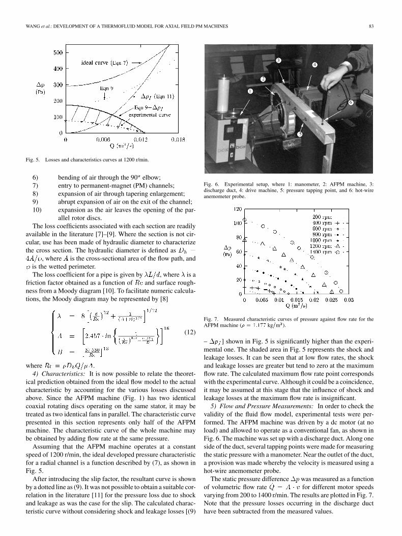
Fig. 5. Losses and characteristics curves at 1200 r/min.
6) bending of air through the 90 elbow;7) entry to permanent-magnet (PM) channels;8) expansion of air through tapering enlargement;9) abrupt expansion of air on the exit of the channel;10) expansion as the air leaves the opening of the par-
allel rotor discs.The loss coefficients associated with each section are readily
available in the literature [7]–[9]. Where the section is not cir-cular, use has been made of hydraulic diameter to characterizethe cross section. The hydraulic diameter is defined as
, where is the cross-sectional area of the flow path, andis the wetted perimeter.The loss coefficient for a pipe is given by , where is a
friction factor obtained as a function of and surface rough-ness from a Moody diagram [10]. To facilitate numeric calcula-tions, the Moody diagram may be represented by [8]
(12)
where .4) Characteristics: It is now possible to relate the theoret-
ical prediction obtained from the ideal flow model to the actualcharacteristic by accounting for the various losses discussedabove. Since the AFPM machine (Fig. 1) has two identicalcoaxial rotating discs operating on the same stator, it may betreated as two identical fans in parallel. The characteristic curvepresented in this section represents only half of the AFPMmachine. The characteristic curve of the whole machine maybe obtained by adding flow rate at the same pressure.
Assuming that the AFPM machine operates at a constantspeed of 1200 r/min, the ideal developed pressure characteristicfor a radial channel is a function described by (7), as shown inFig. 5.
After introducing the slip factor, the resultant curve is shownby a dotted line as (9). It was not possible to obtain a suitable cor-relation in the literature [11] for the pressure loss due to shockand leakage as was the case for the slip. The calculated charac-teristic curve without considering shock and leakage losses [(9)
Fig. 6. Experimental setup, where 1: manometer, 2: AFPM machine, 3:discharge duct, 4: drive machine, 5: pressure tapping point, and 6: hot-wireanemometer probe.
Fig. 7. Measured characteristic curves of pressure against flow rate for theAFPM machine (� = 1:177 kg=m ).
– ] shown in Fig. 5 is significantly higher than the experi-mental one. The shaded area in Fig. 5 represents the shock andleakage losses. It can be seen that at low flow rates, the shockand leakage losses are greater but tend to zero at the maximumflow rate. The calculated maximum flow rate point correspondswith the experimental curve. Although it could be a coincidence,it may be assumed at this stage that the influence of shock andleakage losses at the maximum flow rate is insignificant.
5) Flow and Pressure Measurements: In order to check thevalidity of the fluid flow model, experimental tests were per-formed. The AFPM machine was driven by a dc motor (at noload) and allowed to operate as a conventional fan, as shown inFig. 6. The machine was set up with a discharge duct. Along oneside of the duct, several tapping points were made for measuringthe static pressure with a manometer. Near the outlet of the duct,a provision was made whereby the velocity is measured using ahot-wire anemometer probe.
The static pressure difference was measured as a functionof volumetric flow rate for different motor speedsvarying from 200 to 1400 r/min. The results are plotted in Fig. 7.Note that the pressure losses occurring in the discharge ducthave been subtracted from the measured values.
84 IEEE TRANSACTIONS ON ENERGY CONVERSION, VOL. 20, NO. 1, MARCH 2005
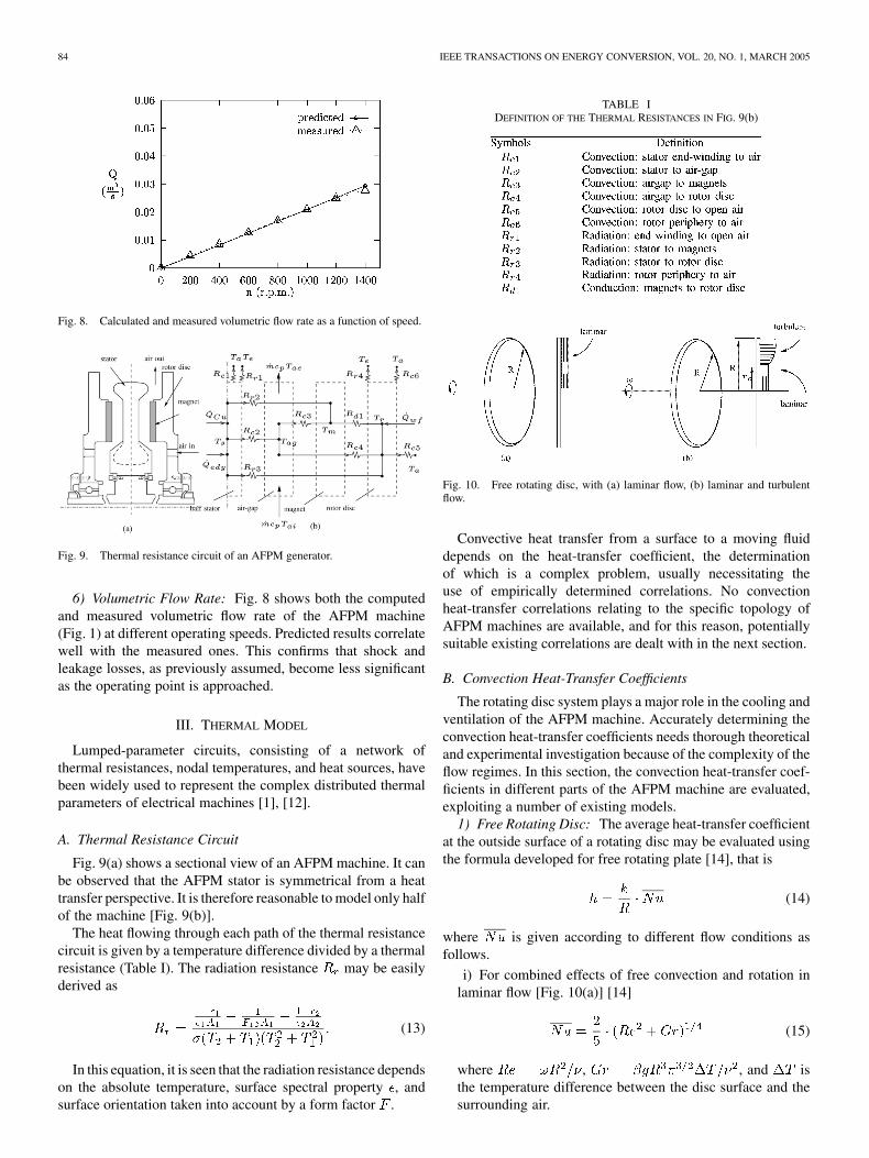
Fig. 8. Calculated and measured volumetric flow rate as a function of speed.
Fig. 9. Thermal resistance circuit of an AFPM generator.
6) Volumetric Flow Rate: Fig. 8 shows both the computedand measured volumetric flow rate of the AFPM machine(Fig. 1) at different operating speeds. Predicted results correlatewell with the measured ones. This confirms that shock andleakage losses, as previously assumed, become less significantas the operating point is approached.
III. THERMAL MODEL
Lumped-parameter circuits, consisting of a network ofthermal resistances, nodal temperatures, and heat sources, havebeen widely used to represent the complex distributed thermalparameters of electrical machines [1], [12].
A. Thermal Resistance Circuit
Fig. 9(a) shows a sectional view of an AFPM machine. It canbe observed that the AFPM stator is symmetrical from a heattransfer perspective. It is therefore reasonable to model only halfof the machine [Fig. 9(b)].
The heat flowing through each path of the thermal resistancecircuit is given by a temperature difference divided by a thermalresistance (Table I). The radiation resistance may be easilyderived as
(13)
In this equation, it is seen that the radiation resistance dependson the absolute temperature, surface spectral property , andsurface orientation taken into account by a form factor .
TABLE IDEFINITION OF THE THERMAL RESISTANCES IN FIG. 9(b)
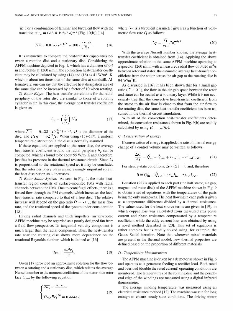
Fig. 10. Free rotating disc, with (a) laminar flow, (b) laminar and turbulentflow.
Convective heat transfer from a surface to a moving fluiddepends on the heat-transfer coefficient, the determinationof which is a complex problem, usually necessitating theuse of empirically determined correlations. No convectionheat-transfer correlations relating to the specific topology ofAFPM machines are available, and for this reason, potentiallysuitable existing correlations are dealt with in the next section.
B. Convection Heat-Transfer Coefficients
The rotating disc system plays a major role in the cooling andventilation of the AFPM machine. Accurately determining theconvection heat-transfer coefficients needs thorough theoreticaland experimental investigation because of the complexity of theflow regimes. In this section, the convection heat-transfer coef-ficients in different parts of the AFPM machine are evaluated,exploiting a number of existing models.
1) Free Rotating Disc: The average heat-transfer coefficientat the outside surface of a rotating disc may be evaluated usingthe formula developed for free rotating plate [14], that is
(14)
where is given according to different flow conditions asfollows.
i) For combined effects of free convection and rotation inlaminar flow [Fig. 10(a)] [14]
(15)
where , , and isthe temperature difference between the disc surface and thesurrounding air.
WANG et al.: DEVELOPMENT OF A THERMOFLUID MODEL FOR AXIAL FIELD PM MACHINES 85
ii) For a combination of laminar and turbulent flow with thetransition at [Fig. 10(b)] [14]
(16)
It is instructive to compare the heat-transfer capabilities be-tween a rotation disc and a stationary disc. Considering theAFPM machine depicted in Fig. 1, which has a diameter of 0.4m and rotates at 1260 r/min, the convection heat-transfer coeffi-cient may be calculated by using (14) and (16) as 41 W/m K,which is about ten times that of the same disc at standstill. Al-ternatively, one can say that the effective heat dissipation area ofthe same disc can be increased by a factor of 10 when rotating.
2) Rotor Edge: The heat-transfer correlations for the radialperiphery of the rotor disc are similar to those of a rotatingcylinder in air. In this case, the average heat transfer coefficientis given as
(17)
where , is the diameter of thedisc, and . When using (15)–(17), a uniformtemperature distribution in the disc is normally assumed.
If these equations are applied to the rotor disc, the averageheat-transfer coefficient around the radial periphery can becomputed, which is found to be about 95 W/m K and, therefore,justifies its presence in the thermal resistance circuit. Sinceis proportional to the rotational speed , it may be concludedthat the rotor periphery plays an increasingly important role inthe heat dissipation as increases.
3) Rotor-Stator System: As seen in Fig. 1, the main heat-transfer region consists of surface-mounted PMs with radialchannels between the PMs. Due to centrifugal effects, there is aforced flow through the PM channels, which increases the localheat-transfer rate compared to that of a free disc. The relativeincrease will depend on the gap ratio , the mass flowrate, and the rotational speed of the system under consideration[15].
Having radial channels and thick impellers, an air-cooledAFPM machine may be regarded as a poorly designed fan froma fluid flow perspective. Its tangential velocity component ismuch larger than the radial component. Thus, the heat-transferrate near the rotating disc shows more dependence on therotational Reynolds number, which is defined as [16]
(18)
Owen [17] provided an approximate solution for the flow be-tween a rotating and a stationary disc, which relates the averageNusselt number to the moment coefficient of the stator-side rotorface by the following equation:
(19)
where is a turbulent parameter given as a function of volu-metric flow rate as follows:
(20)
With the average Nusselt number known, the average heat-transfer coefficient is obtained from (14). Applying the aboveapproximate solution to the same AFPM machine operating ata speed of 1260 r/min with a measured radial flow of 0.026 m /sbetween rotor and stator, the estimated average heat-transfer co-efficient from the stator across the air gap to the rotating disc is94 W/m K.
As discussed in [16], it has been shown that for a small gapratio ( ), the flow in the air-gap space between the rotorand stator can be treated as a boundary layer. While it is not nec-essarily true that the convective heat-transfer coefficient fromthe stator to the air flow is close to that from the air flow tothe rotating disc, the same heat-transfer coefficient has been as-sumed in the thermal circuit simulation.
With all of the convection heat-transfer coefficients deter-mined, the convection resistances shown in Fig. 9(b) are readilycalculated by using .
C. Conservation of Energy
If conservation of energy is applied, the rate of internal energychange of a control volume may be written as follows:
(21)
For steady-state conditions, and, therefore
(22)
Equation (22) is applied to each part (the half stator, air gap,magnet, and rotor disc) of the AFPM machine shown in Fig. 9to obtain a set of equations with the temperatures of the partsbeing the only unknowns. The heat flowing in each path is givenas a temperature difference divided by a thermal resistance.The values used for the heat source terms are given in [19], inwhich copper loss was calculated from measured rms phasecurrent and phase resistance compensated by a temperaturecoefficient while the eddy current loss was obtained by usinga novel method described in [20]. This set of equations israther complex but is readily solved using, for example, theGauss–Seidel iteration. Note that wherever mixed materialsare present in the thermal model, new thermal properties aredefined based on the proportion of different materials.
D. Temperature Measurements
The AFPM machine is driven by a dc motor as shown in Fig. 6and operates as a generator feeding a rectifier load. Both ratedand overload (double the rated current) operating conditions aremonitored. The temperatures of the rotating disc and the periph-eral edge of the windings are measured using a digital infraredthermometer.
The average winding temperature was measured using anelectrical resistance method [12]. The machine was run for longenough to ensure steady-state conditions. The driving motor
86 IEEE TRANSACTIONS ON ENERGY CONVERSION, VOL. 20, NO. 1, MARCH 2005
TABLE IIPREDICTED AND MEASURED TEMPERATURE RISES (T = 23:75 C,
I = 30 A, n = 1217 r/min)
TABLE IIIPREDICTED AND MEASURED TEMPERATURE RISES (T = 24 C,
I = 60 A, n = 1263 r/min)
was then shut down, and when the machine came to standstill,the electrical resistances of the three phases of the windingswere measured as a function of time. A suitable curve wasfitted to these resistance measurements, and the resistance thatthe winding would have had when the machine was shut downwas determined by extrapolating back in time.
For ensuring the validity of the measurements, the first resis-tance reading should be taken within 30 s after switching off thepower to the driving motor. The average temperature rise in thestator winding is then obtained by using the following equation:
(23)
where is a constant ( for copper winding,for aluminum winding), is the ambient temperature, is thecold winding temperature, and and are the cold and hotwinding resistances, respectively.
IV. COMPARISON OF RESULTS
The computed values of the temperature rise in the variousparts of the AFPM machine are compared with the corre-sponding measurements in Tables II and III. The calculatedresults agree reasonably well with the tested results, consid-ering the relatively simple thermal resistance network used torepresent the AFPM machine.
V. APPLICATION
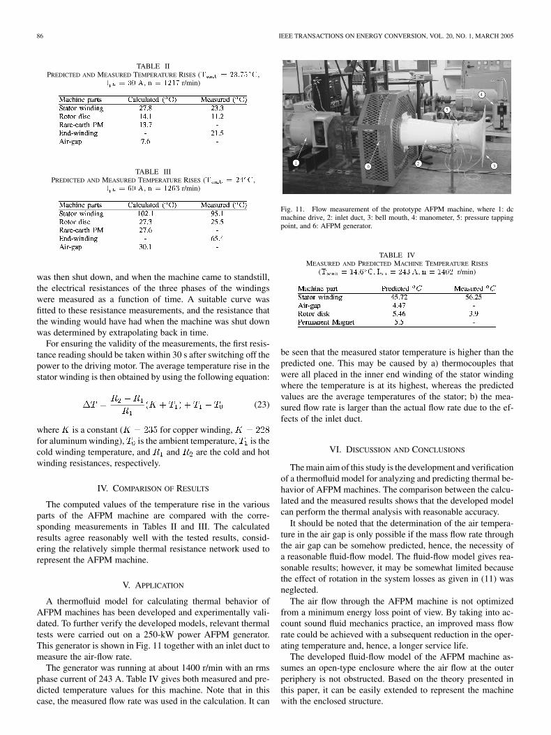
A thermofluid model for calculating thermal behavior ofAFPM machines has been developed and experimentally vali-dated. To further verify the developed models, relevant thermaltests were carried out on a 250-kW power AFPM generator.This generator is shown in Fig. 11 together with an inlet duct tomeasure the air-flow rate.
The generator was running at about 1400 r/min with an rmsphase current of 243 A. Table IV gives both measured and pre-dicted temperature values for this machine. Note that in thiscase, the measured flow rate was used in the calculation. It can
Fig. 11. Flow measurement of the prototype AFPM machine, where 1: dcmachine drive, 2: inlet duct, 3: bell mouth, 4: manometer, 5: pressure tappingpoint, and 6: AFPM generator.
TABLE IVMEASURED AND PREDICTED MACHINE TEMPERATURE RISES
(T = 14:6 C, I = 243 A, n = 1402 r/min)
be seen that the measured stator temperature is higher than thepredicted one. This may be caused by a) thermocouples thatwere all placed in the inner end winding of the stator windingwhere the temperature is at its highest, whereas the predictedvalues are the average temperatures of the stator; b) the mea-sured flow rate is larger than the actual flow rate due to the ef-fects of the inlet duct.
VI. DISCUSSION AND CONCLUSIONS
The main aim of this study is the development and verificationof a thermofluid model for analyzing and predicting thermal be-havior of AFPM machines. The comparison between the calcu-lated and the measured results shows that the developed modelcan perform the thermal analysis with reasonable accuracy.
It should be noted that the determination of the air tempera-ture in the air gap is only possible if the mass flow rate throughthe air gap can be somehow predicted, hence, the necessity ofa reasonable fluid-flow model. The fluid-flow model gives rea-sonable results; however, it may be somewhat limited becausethe effect of rotation in the system losses as given in (11) wasneglected.
The air flow through the AFPM machine is not optimizedfrom a minimum energy loss point of view. By taking into ac-count sound fluid mechanics practice, an improved mass flowrate could be achieved with a subsequent reduction in the oper-ating temperature and, hence, a longer service life.
The developed fluid-flow model of the AFPM machine as-sumes an open-type enclosure where the air flow at the outerperiphery is not obstructed. Based on the theory presented inthis paper, it can be easily extended to represent the machinewith the enclosed structure.
WANG et al.: DEVELOPMENT OF A THERMOFLUID MODEL FOR AXIAL FIELD PM MACHINES 87
REFERENCES
[1] E. Spooner and B. J. Chalmers, “TORUS: A slotless, toroidal-stator,permanent-magnet generator,” Proc. Inst. Elect. Eng., B, vol. 139, pp.497–506, 1992.
[2] C. C. Chan, “Axial-field electrical machines with yokeless armaturecore,” Ph.D. dissertation, Univ. Hong Kong, 1982.
[3] J. F. Gieras and M. Wing, Permanent Magnet Motor Technology: Designand Applications. New York: Marcel Dekker, 1997.
[4] J. F. Douglas, J. M. Gasiorek, and J. A. Swaffield, Fluid Me-chanics. White Plains, NY: Longman, 1995.
[5] A. T. Sayers, Hydraulic and Compressible Flow Turbomachines. NewYork: McGraw-Hill, 1990.
[6] F. M. White et al., Fluid Mechanics. New York: McGraw-Hill, 1994.[7] B. R. Munson, D. F. Young, and T. H. Okiishi, Fundamentals of Fluid
Mechanics. New York: Wiley, 1994.[8] D. Chisholm, Two-Phase Flow in Pipelines and Heat Ex-
changers. New York: George Godwin, 1983.[9] D. S. Miller, Internal Flow Systems. Cranfield, U.K.: BHRA (Infor-
mation Services), 1990.[10] A. F. Mills, Basic Heat and Mass Transfer. Homewood, IL: Irwin,
1995.[11] P. J. Strachan, F. P. Reynaud, and T. W. von Backström, “The hydrody-
namic modeling of torque converters,” R & D J., vol. 8, no. 1, pp. 21–29,1992.
[12] Handbook of Electric Motors, R. H. Engelmann and W. H. Middendorf,Eds., Marcel Dekker, New York, 1995.
[13] Heat and Mass Transfer in Rotating Machinery, D. E. Metzger and N.H. Afgan, Eds., Hemisphere, Washington, DC, 1984.
[14] W. Y. Wong, Heat Transfer for Engineers. White Plains, NY:Longman, 1977.
[15] J. M. Owen, “The effect of forced flow on heat transfer from a disc ro-tating near a stator,” Int. J. Heat Mass Transfer, vol. 14, pp. 1135–1147,1971.
[16] , “The Reynolds analogy applied to flow between a rotating and astationary disc,” Int. J. Heat Mass Transfer, vol. 14, pp. 451–460, 1971.
[17] , “An approximate solution for the flow between a rotating and astationary disk,” ASME J. Turbomach., vol. 111, no. 4, pp. 323–332,1989.
[18] J. M. Owen and R. H. Rogers, Flow and Heat Transfer in Rotating-DiscSystems. Baldock, U.K.: Research Studies, 1989, vol. 1.
[19] N. F. Lombard, “Design and evaluation of an ironless stator axial fluxpermanent magnet machine,” M.Sc. thesis, Univ. Stellenbosch, Dept.Elect. Eng., Matieland, South Africa, 1997.
[20] R. Wang and M. J. Kamper, “Evaluation of eddy current losses in axialflux permanent magnet (AFPM) machine with an ironless stator,” inProc. IEEE Ind. Appl. Soc. Conf. Rec., Pittsburgh, PA, 2002.
Rong-Jie Wang (M’00) received the M.Sc. (Eng.)degree from the University of Cape Town, CapeTown, South Africa, in 1998 and the Ph.D. (Eng.) de-gree from the University of Stellenbosch, Matieland,South Africa, in 2003.
Currently, he is a Postdoctoral Research Fellow inthe Department of Electrical Engineering, Universityof Stellenbosch. His research area is on special elec-trical machines, design optimization of electrical ma-chines using the finite element method, thermal mod-eling of electrical machines, and renewable energy
systems.
Maarten J. Kamper (M’96) received the M.Sc.(Eng.) and Ph.D. (Eng.) degrees from the Universityof Stellenbosch, Matieland, South Africa, in 1987and 1996, respectively.
Currently, he is a Professor in the Departmentof Electrical Engineering, University of Stellen-bosch. He was a Researcher with the SA TransportServices and the SA Council for Scientific andIndustrial Research (CSIR) for several years. Heis a South African National Research Foundation(NRF)-supported scientist. His research area is
on computer-aided design and control of reluctance synchronous, switchedreluctance, and permanent-magnet machine drives.
Robert T. Dobson received the B.Sc. (Eng.) degreein mechanical engineering from the University ofWitwatersrand, Johannesburg, South Africa, in 1969and the M.Sc. (Eng.) degree in nuclear engineeringfrom the University of Cape Town, Cape Town,South Africa, in 1970.
Currently, he is a Senior Lecturer at the Universityof Stellenbosch, Matieland, South Africa, where hehas been since 1988. He worked in the South Africanindustry for 17 years before joining the lecturing
staff. His research interests include energy production using natural circulationthermosyphon loops and thermal management and control using heat pipes.
Related Documents