Transfer switches SIRCOVER 250 A SIRCOVER Manual Transfer Switching Equipment from 125 to 3200 A Function Advantages SIRCOVER products are manually operated transfer switches with positive break indication. There are 4 ranges in the series: • SIRCOVER for open transition switching (I-0-II) available in 3 or 4 pole. • SIRCOVER for overlapping contact switching (I-I+II-II). For applications where both sources are synchronised and there is to be no interruption to the load supply during transfer - available in 3 or 4 pole. • SIRCOVER Bypass. This combination of three interlocked load break switches provides 3+6 or 4+8 poles for bypass applications. • SIRCOVER Bypass for overlapping contact switching (I-I+II-II). This combination of three interlocked load break switches provides bypass to an UPS or other devices when sources are synchronised and the UPS is on static bypass mode. They provide on-load transfer between two sources for any low voltage power circuit, as well as safety isolation by double breaking per pole. Other applications include source inversion (e.g. to change the direction of a motor) or grounding/earthing. A complete range There are 4 SIRCOVER models to meet every need: The standard model I-0-II, the overlapping contact model I-I+II-II, the bypass model and the bypass with overlapping contact model I-I+II-II. Easy to connect For ratings of 2000 to 3200 A, we offer copper bar connection pieces. This gives you the option of different connection methods - flat, edgewise with top or bottom bridging. Stable positions SIRCOVER devices have three stable positions, unaffected by voltage fluctuations and vibrations, protecting your loads from network disturbances. On-load switching With its AC-23 and AC-33 characteristics, tested according to standards IEC 60947-3 and IEC 60947-6-1, the SIRCOVER enables safe on-load switching for any type of load. With its on-load transfer capabilities, it is not necessary to isolate loads prior to transfer therefore the SIRCOVER offers an economical solution. > Manufacturing > Power distribution The solution for > Complete range > Easy to connect > Stable positions > On-load switching Strong points > IEC 60947-6,-1 > IEC 60947-3 > GB 14048-11 Conformity to standards svr_151_a svr_214_a SIRCOVER Bypass 500 A Approvals and certifications (1) (1) Product references on request. BUREAU VERITAS 396 General Catalogue 2018

Welcome message from author
This document is posted to help you gain knowledge. Please leave a comment to let me know what you think about it! Share it to your friends and learn new things together.
Transcript

Tran
sfer
sw
itch
es
SIRCOVER 250 A
SIRCOVERManual Transfer Switching Equipmentfrom 125 to 3200 A
Function
Advantages
SIRCOVER products are manually operated transfer switches with positive break indication.There are 4 ranges in the series: • SIRCOVER for open transition switching (I-0-II) available in 3 or 4 pole. • SIRCOVER for overlapping contact switching (I-I+II-II). For applications where both sources are synchronised and there is to be no interruption to the load supply during transfer - available in 3 or 4 pole.
• SIRCOVER Bypass. This combination of three interlocked load break switches provides 3+6 or 4+8 poles for bypass applications.
• SIRCOVER Bypass for overlapping contact switching (I-I+II-II). This combination of three interlocked load break switches provides bypass to an UPS or other devices when sources are synchronised and the UPS is on static bypass mode.
They provide on-load transfer between two sources for any low voltage power circuit, as well as safety isolation by double breaking per pole. Other applications include source inversion (e.g. to change the direction of a motor) or grounding/earthing.
A complete rangeThere are 4 SIRCOVER models to meet every need: The standard model I-0-II, the overlapping contact model I-I+II-II, the bypass model and the bypass with overlapping contact model I-I+II-II.
Easy to connectFor ratings of 2000 to 3200 A, we offer copper bar connection pieces. This gives you the option of different connection methods - flat, edgewise with top or bottom bridging.
Stable positionsSIRCOVER devices have three stable positions, unaffected by voltage fluctuations and vibrations, protecting your loads from network disturbances.
On-load switchingWith its AC-23 and AC-33 characteristics, tested according to standards IEC 60947-3 and IEC 60947-6-1, the SIRCOVER enables safe on-load switching for any type of load. With its on-load transfer capabilities, it is not necessary to isolate loads prior to transfer therefore the SIRCOVER offers an economical solution.
> Manufacturing > Power distribution
The solution for
> Complete range > Easy to connect > Stable positions > On-load switching
Strong points
> IEC 60947-6,-1 > IEC 60947-3 > GB 14048-11
Conformity to standards
svr_
151_
a
svr_
214_
a
SIRCOVER Bypass500 A
Approvals and certifications(1)
(1) Product references on request.
B U R E A UV E R I T A S
SIRCOVERManual Transfer Switching Equipment
from 125 to 3200 A
svr_
136_
a_1_
x_ca
t
What you need to know
acce
s_46
2_a
Top or bottom flat connection
acce
s_46
3_a
Top or bottomedgewise connection
acce
s_23
1_a_
1_ca
t
Top or bottombridging connection
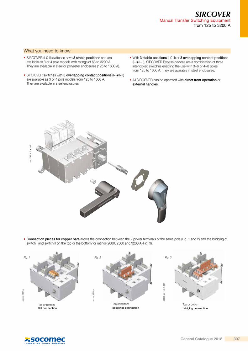
• Connection pieces for copper bars allows the connection between the 2 power terminals of the same pole (Fig. 1 and 2) and the bridging of switch I and switch II on the top or the bottom for ratings 2000, 2500 and 3200 A (Fig. 3).
Fig. 1 Fig. 2 Fig. 3
• SIRCOVER (I-0-II) switches have 3 stable positions and are available as 3 or 4 pole models with ratings of 63 to 3200 A. They are available in steel or polyester enclosures (125 to 1600 A).
• SIRCOVER switches with 3 overlapping contact positions (I-I+II-II) are available as 3 or 4 pole models from 125 to 1600 A. They are available in steel enclosures.
• With 3 stable positions (I-0-II) or 3 overlapping contact positions (I-I+II-II), SIRCOVER Bypass devices are a combination of three interlocked switches enabling the use with 3+6 or 4+8 poles from 125 to 1600 A. They are available in steel enclosures.
• All SIRCOVER can be operated with direct front operation or external handles.
396 General Catalogue 2018
Tran
sfer
sw
itch
es
SIRCOVER 250 A
SIRCOVERManual Transfer Switching Equipmentfrom 125 to 3200 A
Function
Advantages
SIRCOVER products are manually operated transfer switches with positive break indication.There are 4 ranges in the series: • SIRCOVER for open transition switching (I-0-II) available in 3 or 4 pole. • SIRCOVER for overlapping contact switching (I-I+II-II). For applications where both sources are synchronised and there is to be no interruption to the load supply during transfer - available in 3 or 4 pole.
• SIRCOVER Bypass. This combination of three interlocked load break switches provides 3+6 or 4+8 poles for bypass applications.
• SIRCOVER Bypass for overlapping contact switching (I-I+II-II). This combination of three interlocked load break switches provides bypass to an UPS or other devices when sources are synchronised and the UPS is on static bypass mode.
They provide on-load transfer between two sources for any low voltage power circuit, as well as safety isolation by double breaking per pole. Other applications include source inversion (e.g. to change the direction of a motor) or grounding/earthing.
A complete rangeThere are 4 SIRCOVER models to meet every need: The standard model I-0-II, the overlapping contact model I-I+II-II, the bypass model and the bypass with overlapping contact model I-I+II-II.
Easy to connectFor ratings of 2000 to 3200 A, we offer copper bar connection pieces. This gives you the option of different connection methods - flat, edgewise with top or bottom bridging.
Stable positionsSIRCOVER devices have three stable positions, unaffected by voltage fluctuations and vibrations, protecting your loads from network disturbances.
On-load switchingWith its AC-23 and AC-33 characteristics, tested according to standards IEC 60947-3 and IEC 60947-6-1, the SIRCOVER enables safe on-load switching for any type of load. With its on-load transfer capabilities, it is not necessary to isolate loads prior to transfer therefore the SIRCOVER offers an economical solution.
> Manufacturing > Power distribution
The solution for
> Complete range > Easy to connect > Stable positions > On-load switching
Strong points
> IEC 60947-6,-1 > IEC 60947-3 > GB 14048-11
Conformity to standards
svr_
151_
a
svr_
214_
a
SIRCOVER Bypass500 A
Approvals and certifications(1)
(1) Product references on request.
B U R E A UV E R I T A S
SIRCOVERManual Transfer Switching Equipment
from 125 to 3200 Asv
r_13
6_a_
1_x_
cat
What you need to know
acce
s_46
2_a
Top or bottom flat connection
acce
s_46
3_a
Top or bottomedgewise connection
acce
s_23
1_a_
1_ca
t
Top or bottombridging connection
• Connection pieces for copper bars allows the connection between the 2 power terminals of the same pole (Fig. 1 and 2) and the bridging of switch I and switch II on the top or the bottom for ratings 2000, 2500 and 3200 A (Fig. 3).
Fig. 1 Fig. 2 Fig. 3
• SIRCOVER (I-0-II) switches have 3 stable positions and are available as 3 or 4 pole models with ratings of 63 to 3200 A. They are available in steel or polyester enclosures (125 to 1600 A).
• SIRCOVER switches with 3 overlapping contact positions (I-I+II-II) are available as 3 or 4 pole models from 125 to 1600 A. They are available in steel enclosures.
• With 3 stable positions (I-0-II) or 3 overlapping contact positions (I-I+II-II), SIRCOVER Bypass devices are a combination of three interlocked switches enabling the use with 3+6 or 4+8 poles from 125 to 1600 A. They are available in steel enclosures.
• All SIRCOVER can be operated with direct front operation or external handles.
397General Catalogue 2018

SIRCOVERManual Transfer Switching Equipmentfrom 125 to 3200 A
ReferencesSIRCOVER I-0-II
Rating(A) /Frame size No. of poles Switch body Direct handle
External handle
Shaft for external handle Bridging bars
Auxiliary contact
Terminal shrouds
Terminal screens
125 A / B33 P 41AC 3013
J2 typeBlue
1122 1111Red
1123 1111
S2 typeBlack
IP55
1421 2113
IP651423 2113(1)
200 mm1400 1020
320 mm
1400 1032(1)
3 P4109 3019
4 P4109 4019
1st/2nd NO/NC contact
4109 0021(2)
3 P2694 3014(3)(4)
4 P2694 4014(3)(4)
3 P1509 3012
4 P1509 4012
4 P 41AC 4013
160 A / B33 P 41AC 30164 P 41AC 4016
200 A / B33 P 41AC 30204 P 41AC 4020
250 A / B43 P 41AC 3025 4109 3025
3 P2694 3021(3)(4)
4 P2694 4021(3)(4)
3 P1509 3025
4 P1509 4025
4 P 41AC 4025 4109 4025
315 A / B43 P 41AC 3031
3 P4109 3039
4 P4109 4039
4 P 41AC 4031
400 A / B43 P 41AC 30404 P 41AC 4040
500 A / B53 P 41AC 3050 4109 3050
3 P2694 3051(3)(4)
4 P2694 4051(3)(4)
3 P1509 3063
4 P1509 4063
4 P 41AC 4050 4109 4050
630 A / B53 P 41AC 3063 4109 30634 P 41AC 4063 4109 4063
800 A / B63 P 41AC 3080
C1 typeBlack
2799 7052
S4 typeBlack IP65
1443 3113
200 mm1401 1520
320 mm
1401 1532(1)
3 P4109 3080
3 P4109 4080
3 P1509 3080
4 P1509 4080
4 P 41AC 4080
1000 A / B63 P 41AC 31004 P 41AC 4100
1250 A / B63 P 41AC 3120 4109 31204 P 41AC 4120 4109 4120
1600 A / B73 P 41AC 3160 4109 3160 1509 3160
4 P 41AC 4160 4109 4160 1509 4160
2000 A / B83 P 41AC 3200
S5 typeBlack
2799 7042
S5 typeBlack IP65
1453 8113
200 mm2799 3015
320 mm
2799 3018(1)
450 mm2799 3019
(5) 1st and 2nd
NO/NC contact included
included
4 P 41AC 4200
2500 A / B83 P 41AC 32504 P 41AC 4250
3200 A / B83 P 41AC 33204 P 41AC 4320
(1) Standard.(2) 2 contacts supplied: one for position I and one for position II.(3) To fully shroud the front and rear at the top and bottom, order quantity 4.(4) To shroud front switch top and bottom, order quantity 2.(5) See “Copper bar connection pieces”
Operating principle
1 2 1 21 2
I 0 II svr_
225_
a_1_
x_ca
t.aiManual Transfer
Switch
svr_
224_
a_1_
x_ca
t.ai
SIRCOVER I-0-II
SIRCOVERManual Transfer Switching Equipment
from 125 to 3200 A
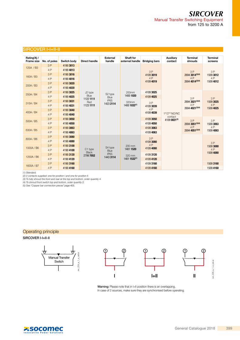
SIRCOVER I-I+II-II
Rating(A) / Frame size No. of poles Switch body Direct handle
External handle
Shaft for external handle Bridging bars
Auxiliary contact
Terminal shrouds
Terminal screens
125A / B33 P 4190 3013
J2 typeBlue
1122 1111Red
1123 1111
S2 typeBlue IP65
1423 2114
200mm1400 1020
320mm1400 1032(1)
3 P4109 3019
4 P4109 4019
1st/2nd NO/NCcontact
4109 0021(2)
3 P2694 3014(3)(4)
4 P2694 4014(3)(4)
3 P1509 3012
4 P1509 4012
4 P 4190 4013
160A / B33 P 4190 30164 P 4190 4016
200A / B33 P 4190 30204 P 4190 4020
250A / B43 P 4190 3025 4109 3025
3 P2694 3021(3)(4)
4 P2694 4021(3)(4)
3 P1509 3025
4 P1509 4025
4 P 4190 4025 4109 4025
315A / B43 P 4190 3031
3 P4109 3039
4 P4109 4039
4 P 4190 4031
400A / B43 P 4190 30404 P 4190 4040
500A / B53 P 4190 3050 4109 3050
3 P2694 3051(3)(4)
4 P2694 4051(3)(4)
3 P1509 3063
4 P1509 4063
4 P 4190 4050 4109 4050
630A / B53 P 4190 3063 4109 30634 P 4190 4063 4109 4063
800A / B63 P 4190 3080
C1 typeBlack
2799 7052
S4 typeBlue IP65
1443 3114
200 mm1401 1520
320 mm1401 1532(1)
3 P4109 3080
4 P4109 4080
3 P1509 3080
4 P1509 4080
4 P 4190 4080
1000A / B63 P 4190 31004 P 4190 4100
1250A / B63 P 4190 3120 4109 31204 P 4190 4120 4109 4120
1600A / B73 P 4190 3160 4109 3160 1509 31604 P 4190 4160 4109 4160 1509 4160
(1) Standard. (2) 2 contacts supplied: one for position I and one for position II.(3) To fully shroud the front and rear at the top and bottom, order quantity 4.(4) To shroud front switch top and bottom, order quantity 2.(5) See “Copper bar connection pieces”
Operating principle
Warning: Please note that in I+II position there is an overlapping. In case of 2 sources, make sure they are synchronised before operating.
SIRCOVER I-I+II-II
Manual TransferSwitch
svr_
224_
a_1_
x_ca
t.ai 1 2 1 2
I I+II II
1 2
svr_
226_
a_1_
x_ca
t.ai
page 405.
398 General Catalogue 2018
SIRCOVERManual Transfer Switching Equipmentfrom 125 to 3200 A
ReferencesSIRCOVER I-0-II
Rating(A) /Frame size No. of poles Switch body Direct handle
External handle
Shaft for external handle Bridging bars
Auxiliary contact
Terminal shrouds
Terminal screens
125 A / B33 P 41AC 3013
J2 typeBlue
1122 1111Red
1123 1111
S2 typeBlack
IP55
1421 2113
IP651423 2113(1)
200 mm1400 1020
320 mm
1400 1032(1)
3 P4109 3019
4 P4109 4019
1st/2nd NO/NC contact
4109 0021(2)
3 P2694 3014(3)(4)
4 P2694 4014(3)(4)
3 P1509 3012
4 P1509 4012
4 P 41AC 4013
160 A / B33 P 41AC 30164 P 41AC 4016
200 A / B33 P 41AC 30204 P 41AC 4020
250 A / B43 P 41AC 3025 4109 3025
3 P2694 3021(3)(4)
4 P2694 4021(3)(4)
3 P1509 3025
4 P1509 4025
4 P 41AC 4025 4109 4025
315 A / B43 P 41AC 3031
3 P4109 3039
4 P4109 4039
4 P 41AC 4031
400 A / B43 P 41AC 30404 P 41AC 4040
500 A / B53 P 41AC 3050 4109 3050
3 P2694 3051(3)(4)
4 P2694 4051(3)(4)
3 P1509 3063
4 P1509 4063
4 P 41AC 4050 4109 4050
630 A / B53 P 41AC 3063 4109 30634 P 41AC 4063 4109 4063
800 A / B63 P 41AC 3080
C1 typeBlack
2799 7052
S4 typeBlack IP65
1443 3113
200 mm1401 1520
320 mm
1401 1532(1)
3 P4109 3080
3 P4109 4080
3 P1509 3080
4 P1509 4080
4 P 41AC 4080
1000 A / B63 P 41AC 31004 P 41AC 4100
1250 A / B63 P 41AC 3120 4109 31204 P 41AC 4120 4109 4120
1600 A / B73 P 41AC 3160 4109 3160 1509 3160
4 P 41AC 4160 4109 4160 1509 4160
2000 A / B83 P 41AC 3200
S5 typeBlack
2799 7042
S5 typeBlack IP65
1453 8113
200 mm2799 3015
320 mm
2799 3018(1)
450 mm2799 3019
(5) 1st and 2nd
NO/NC contact included
included
4 P 41AC 4200
2500 A / B83 P 41AC 32504 P 41AC 4250
3200 A / B83 P 41AC 33204 P 41AC 4320
(1) Standard.(2) 2 contacts supplied: one for position I and one for position II.(3) To fully shroud the front and rear at the top and bottom, order quantity 4.(4) To shroud front switch top and bottom, order quantity 2.(5) See “Copper bar connection pieces”
Operating principle
1 2 1 21 2
I 0 II svr_
225_
a_1_
x_ca
t.aiManual Transfer
Switch
svr_
224_
a_1_
x_ca
t.ai
SIRCOVER I-0-II
SIRCOVERManual Transfer Switching Equipment
from 125 to 3200 A
SIRCOVER I-I+II-II
Rating(A) / Frame size No. of poles Switch body Direct handle
External handle
Shaft for external handle Bridging bars
Auxiliary contact
Terminal shrouds
Terminal screens
125A / B33 P 4190 3013
J2 typeBlue
1122 1111Red
1123 1111
S2 typeBlue IP65
1423 2114
200mm1400 1020
320mm1400 1032(1)
3 P4109 3019
4 P4109 4019
1st/2nd NO/NCcontact
4109 0021(2)
3 P2694 3014(3)(4)
4 P2694 4014(3)(4)
3 P1509 3012
4 P1509 4012
4 P 4190 4013
160A / B33 P 4190 30164 P 4190 4016
200A / B33 P 4190 30204 P 4190 4020
250A / B43 P 4190 3025 4109 3025
3 P2694 3021(3)(4)
4 P2694 4021(3)(4)
3 P1509 3025
4 P1509 4025
4 P 4190 4025 4109 4025
315A / B43 P 4190 3031
3 P4109 3039
4 P4109 4039
4 P 4190 4031
400A / B43 P 4190 30404 P 4190 4040
500A / B53 P 4190 3050 4109 3050
3 P2694 3051(3)(4)
4 P2694 4051(3)(4)
3 P1509 3063
4 P1509 4063
4 P 4190 4050 4109 4050
630A / B53 P 4190 3063 4109 30634 P 4190 4063 4109 4063
800A / B63 P 4190 3080
C1 typeBlack
2799 7052
S4 typeBlue IP65
1443 3114
200 mm1401 1520
320 mm1401 1532(1)
3 P4109 3080
4 P4109 4080
3 P1509 3080
4 P1509 4080
4 P 4190 4080
1000A / B63 P 4190 31004 P 4190 4100
1250A / B63 P 4190 3120 4109 31204 P 4190 4120 4109 4120
1600A / B73 P 4190 3160 4109 3160 1509 31604 P 4190 4160 4109 4160 1509 4160
(1) Standard. (2) 2 contacts supplied: one for position I and one for position II.(3) To fully shroud the front and rear at the top and bottom, order quantity 4.(4) To shroud front switch top and bottom, order quantity 2.(5) See “Copper bar connection pieces”
Operating principle
Warning: Please note that in I+II position there is an overlapping. In case of 2 sources, make sure they are synchronised before operating.
SIRCOVER I-I+II-II
Manual TransferSwitch
svr_
224_
a_1_
x_ca
t.ai 1 2 1 2
I I+II II
1 2
svr_
226_
a_1_
x_ca
t.ai
page 405.
399General Catalogue 2018

SIRCOVERManual Transfer Switching Equipmentfrom 125 to 3200 A
References (continued)SIRCOVER Bypass I-0-II
Rating(A) / Frame size No. of poles Switch body Direct handle
External handle
Shaft for external handle Bridging bars
Auxiliary contact
Terminal shrouds
Terminal screens
125 A / B33 P 4100 7013
J2 typeBlue
1122 1111Red
1123 1111
S2 typeBlue
IP55
1421 2113
IP651423 2113(1)
200 mm1400 1020
320mm1400 1032(1)
3 P2x 4109 3019
4 P2x 4109 4019
1st/2nd NO/NCcontact
4109 0021(2)
3 P2694 3014(3)(4)
4 P2694 4014(3)(4)
3 P1509 3012
4 P1509 4012
4 P 4100 9013
160 A / B33 P 4100 70164 P 4100 9016
200 A / B33 P 4100 70204 P 4100 9020
250 A / B43 P 4100 7025
C1 typeBlack
2799 7052
S3 typeBlue IP65
1433 3113
200 mm1400 1520
320 mm1400 1532(1)
2x 4109 3025
3 P2694 3021(3)(4)
4 P2694 4021(3)(4)
3 P1509 3025
4 P1509 4025
4 P 4100 9025 2x 4109 4025
315 A / B43 P 4100 7031
3 P2x 4109 3039
4 P2x 4109 4039
4 P 4100 9031
400 A / B43 P 4100 70404 P 4100 9040
500 A / B53 P 4100 7050 2x 4109 3050
3 P2694 3051(3)(4)
4 P2694 4051(3)(4)
3 P1509 3063
4 P1509 4063
4 P 4100 9050 2x 4109 4050
630 A / B53 P 4100 7063 2x 4109 30634 P 4100 9063 2x 4109 4063
800 A / B63 P 4100 7080
C2 typeBlack
2799 7012(5)
V2 typeBlack IP65
4199 7146
200 mm2799 3015
320 mm2799 3018(1)
450 mm2799 3019
3 P2x 4109 3080
4 P2x 4109 4080
3 P1509 3080
4 P1509 4080
4 P 4100 9080
1000 A / B63 P 4100 71004 P 4100 9100
1250 A / B63 P 4100 7120 2x 4109 31204 P 4100 9120 2x 4109 4120
1600 A / B73 P 4100 7160 2x 4109 3160 1509 31604 P 4100 9160 2x 4109 4160 1509 4160
(1) Standard.(2) 2 contacts supplied: one for position I and one for position II.(3) To fully shroud the front and rear at the top and bottom, order quantity 6(or 4 if using bridging bars).(4) To shroud front switch top and bottom, order quantity 2.(5) Double lever handle.
Operating principleSIRCOVER Bypass I-0-II
I 0 II
UPS UPSUPS UPS
svr_
227_
a_1_
x_ca
t.ai
SIRCOVERManual Transfer Switching Equipment
from 125 to 3200 A
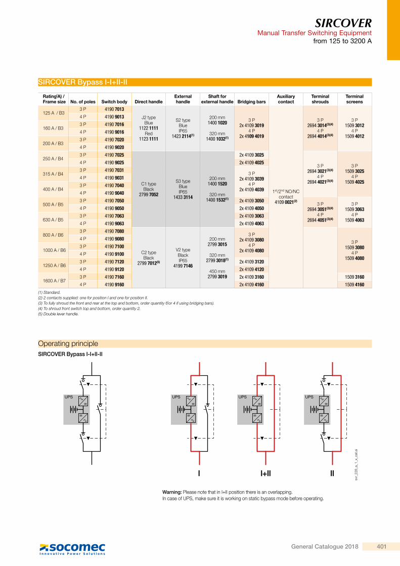
SIRCOVER Bypass I-I+II-II
Rating(A) / Frame size No. of poles Switch body Direct handle
External handle
Shaft for external handle Bridging bars
Auxiliary contact
Terminal shrouds
Terminal screens
125 A / B33 P 4190 7013
J2 typeBlue
1122 1111Red
1123 1111
S2 typeBlue IP65
1423 2114(1)
200 mm1400 1020
320 mm1400 1032(1)
3 P2x 4109 3019
4 P2x 4109 4019
1st/2nd NO/NCcontact
4109 0021(2)
3 P2694 3014(3)(4)
4 P2694 4014(3)(4)
3 P1509 3012
4 P1509 4012
4 P 4190 9013
160 A / B33 P 4190 70164 P 4190 9016
200 A / B33 P 4190 70204 P 4190 9020
250 A / B43 P 4190 7025
C1 typeBlack
2799 7052
S3 typeBlue IP65
1433 3114
200 mm1400 1520
320 mm1400 1532(1)
2x 4109 3025
3 P2694 3021(3)(4)
4 P2694 4021(3)(4)
3 P1509 3025
4 P1509 4025
4 P 4190 9025 2x 4109 4025
315 A / B43 P 4190 7031
3 P2x 4109 3039
4 P2x 4109 4039
4 P 4190 9031
400 A / B43 P 4190 70404 P 4190 9040
500 A / B53 P 4190 7050 2x 4109 3050
3 P2694 3051(3)(4)
4 P2694 4051(3)(4)
3 P1509 3063
4 P1509 4063
4 P 4190 9050 2x 4109 4050
630 A / B53 P 4190 7063 2x 4109 30634 P 4190 9063 2x 4109 4063
800 A / B63 P 4190 7080
C2 typeBlack
2799 7012(5)
V2 typeBlack IP65
4199 7146
200 mm2799 3015
320 mm2799 3018(1)
450 mm2799 3019
3 P2x 4109 3080
4 P2x 4109 4080
3 P1509 3080
4 P1509 4080
4 P 4190 9080
1000 A / B63 P 4190 71004 P 4190 9100
1250 A / B63 P 4190 7120 2x 4109 31204 P 4190 9120 2x 4109 4120
1600 A / B73 P 4190 7160 2x 4109 3160 1509 31604 P 4190 9160 2x 4109 4160 1509 4160
(1) Standard.(2) 2 contacts supplied: one for position I and one for position II.(3) To fully shroud the front and rear at the top and bottom, order quantity 6(or 4 if using bridging bars).(4) To shroud front switch top and bottom, order quantity 2.(5) Double lever handle.
Operating principle
Warning: Please note that in I+II position there is an overlapping. In case of UPS, make sure it is working on static bypass mode before operating.
SIRCOVER Bypass I-I+II-II
I I+II II
UPS UPSUPS UPS
svr_
228_
a_1_
x_ca
t.ai
400 General Catalogue 2018
SIRCOVERManual Transfer Switching Equipmentfrom 125 to 3200 A
References (continued)SIRCOVER Bypass I-0-II
Rating(A) / Frame size No. of poles Switch body Direct handle
External handle
Shaft for external handle Bridging bars
Auxiliary contact
Terminal shrouds
Terminal screens
125 A / B33 P 4100 7013
J2 typeBlue
1122 1111Red
1123 1111
S2 typeBlue
IP55
1421 2113
IP651423 2113(1)
200 mm1400 1020
320mm1400 1032(1)
3 P2x 4109 3019
4 P2x 4109 4019
1st/2nd NO/NCcontact
4109 0021(2)
3 P2694 3014(3)(4)
4 P2694 4014(3)(4)
3 P1509 3012
4 P1509 4012
4 P 4100 9013
160 A / B33 P 4100 70164 P 4100 9016
200 A / B33 P 4100 70204 P 4100 9020
250 A / B43 P 4100 7025
C1 typeBlack
2799 7052
S3 typeBlue IP65
1433 3113
200 mm1400 1520
320 mm1400 1532(1)
2x 4109 3025
3 P2694 3021(3)(4)
4 P2694 4021(3)(4)
3 P1509 3025
4 P1509 4025
4 P 4100 9025 2x 4109 4025
315 A / B43 P 4100 7031
3 P2x 4109 3039
4 P2x 4109 4039
4 P 4100 9031
400 A / B43 P 4100 70404 P 4100 9040
500 A / B53 P 4100 7050 2x 4109 3050
3 P2694 3051(3)(4)
4 P2694 4051(3)(4)
3 P1509 3063
4 P1509 4063
4 P 4100 9050 2x 4109 4050
630 A / B53 P 4100 7063 2x 4109 30634 P 4100 9063 2x 4109 4063
800 A / B63 P 4100 7080
C2 typeBlack
2799 7012(5)
V2 typeBlack IP65
4199 7146
200 mm2799 3015
320 mm2799 3018(1)
450 mm2799 3019
3 P2x 4109 3080
4 P2x 4109 4080
3 P1509 3080
4 P1509 4080
4 P 4100 9080
1000 A / B63 P 4100 71004 P 4100 9100
1250 A / B63 P 4100 7120 2x 4109 31204 P 4100 9120 2x 4109 4120
1600 A / B73 P 4100 7160 2x 4109 3160 1509 31604 P 4100 9160 2x 4109 4160 1509 4160
(1) Standard.(2) 2 contacts supplied: one for position I and one for position II.(3) To fully shroud the front and rear at the top and bottom, order quantity 6(or 4 if using bridging bars).(4) To shroud front switch top and bottom, order quantity 2.(5) Double lever handle.
Operating principleSIRCOVER Bypass I-0-II
I 0 II
UPS UPSUPS UPS
svr_
227_
a_1_
x_ca
t.ai
SIRCOVERManual Transfer Switching Equipment
from 125 to 3200 A
SIRCOVER Bypass I-I+II-II
Rating(A) / Frame size No. of poles Switch body Direct handle
External handle
Shaft for external handle Bridging bars
Auxiliary contact
Terminal shrouds
Terminal screens
125 A / B33 P 4190 7013
J2 typeBlue
1122 1111Red
1123 1111
S2 typeBlue IP65
1423 2114(1)
200 mm1400 1020
320 mm1400 1032(1)
3 P2x 4109 3019
4 P2x 4109 4019
1st/2nd NO/NCcontact
4109 0021(2)
3 P2694 3014(3)(4)
4 P2694 4014(3)(4)
3 P1509 3012
4 P1509 4012
4 P 4190 9013
160 A / B33 P 4190 70164 P 4190 9016
200 A / B33 P 4190 70204 P 4190 9020
250 A / B43 P 4190 7025
C1 typeBlack
2799 7052
S3 typeBlue IP65
1433 3114
200 mm1400 1520
320 mm1400 1532(1)
2x 4109 3025
3 P2694 3021(3)(4)
4 P2694 4021(3)(4)
3 P1509 3025
4 P1509 4025
4 P 4190 9025 2x 4109 4025
315 A / B43 P 4190 7031
3 P2x 4109 3039
4 P2x 4109 4039
4 P 4190 9031
400 A / B43 P 4190 70404 P 4190 9040
500 A / B53 P 4190 7050 2x 4109 3050
3 P2694 3051(3)(4)
4 P2694 4051(3)(4)
3 P1509 3063
4 P1509 4063
4 P 4190 9050 2x 4109 4050
630 A / B53 P 4190 7063 2x 4109 30634 P 4190 9063 2x 4109 4063
800 A / B63 P 4190 7080
C2 typeBlack
2799 7012(5)
V2 typeBlack IP65
4199 7146
200 mm2799 3015
320 mm2799 3018(1)
450 mm2799 3019
3 P2x 4109 3080
4 P2x 4109 4080
3 P1509 3080
4 P1509 4080
4 P 4190 9080
1000 A / B63 P 4190 71004 P 4190 9100
1250 A / B63 P 4190 7120 2x 4109 31204 P 4190 9120 2x 4109 4120
1600 A / B73 P 4190 7160 2x 4109 3160 1509 31604 P 4190 9160 2x 4109 4160 1509 4160
(1) Standard.(2) 2 contacts supplied: one for position I and one for position II.(3) To fully shroud the front and rear at the top and bottom, order quantity 6(or 4 if using bridging bars).(4) To shroud front switch top and bottom, order quantity 2.(5) Double lever handle.
Operating principle
Warning: Please note that in I+II position there is an overlapping. In case of UPS, make sure it is working on static bypass mode before operating.
SIRCOVER Bypass I-I+II-II
I I+II II
UPS UPSUPS UPS
svr_
228_
a_1_
x_ca
t.ai
401General Catalogue 2018
SIRCOVERManual Transfer Switching Equipmentfrom 125 to 3200 A
Accessories
External operation handleac
ces_
150_
a_2_
cat
S2 type handle
acce
s_15
1_a_
1_ca
t
S3 type handle acce
s_15
2_a_
2_ca
t
S4 type handle
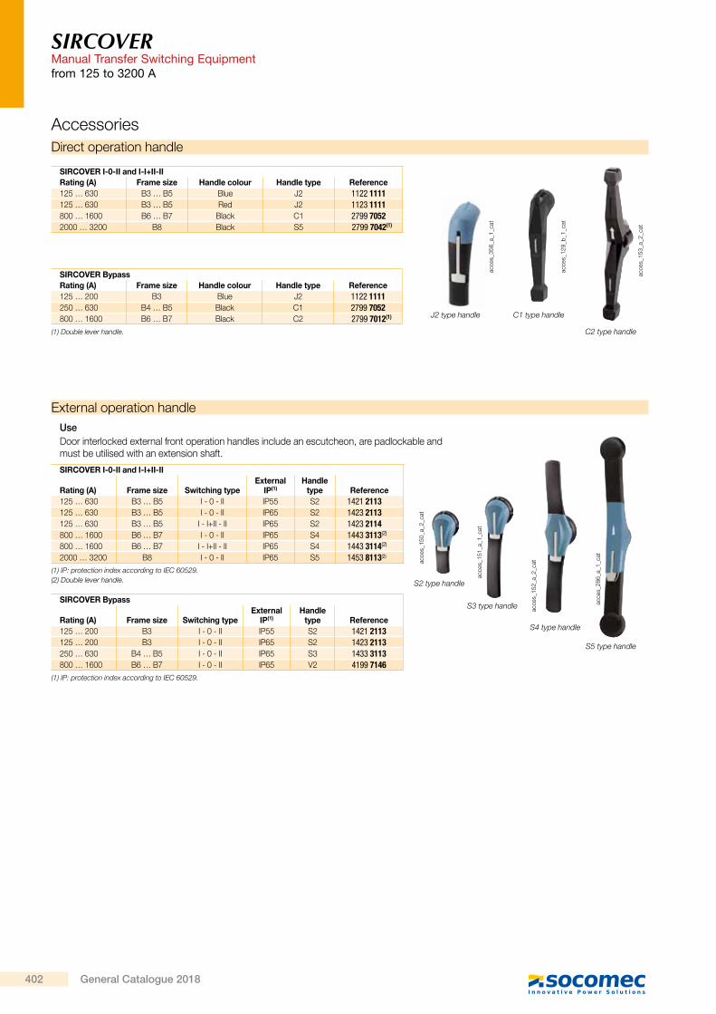
UseDoor interlocked external front operation handles include an escutcheon, are padlockable and must be utilised with an extension shaft.
SIRCOVER I-0-II and I-I+II-II
Rating (A) Frame size Switching typeExternal
IP(1)Handle
type Reference125 … 630 B3 … B5 I - 0 - II IP55 S2 1421 2113125 … 630 B3 … B5 I - 0 - II IP65 S2 1423 2113125 … 630 B3 … B5 I - I+II - II IP65 S2 1423 2114800 … 1600 B6 … B7 I - 0 - II IP65 S4 1443 3113(2)
800 … 1600 B6 … B7 I - I+II - II IP65 S4 1443 3114(2)
2000 … 3200 B8 I - 0 - II IP65 S5 1453 8113(2)
(1) IP: protection index according to IEC 60529.(2) Double lever handle.
SIRCOVER Bypass
Rating (A) Frame size Switching typeExternal
IP(1)Handle
type Reference125 … 200 B3 I - 0 - II IP55 S2 1421 2113125 … 200 B3 I - 0 - II IP65 S2 1423 2113250 … 630 B4 … B5 I - 0 - II IP65 S3 1433 3113800 … 1600 B6 … B7 I - 0 - II IP65 V2 4199 7146
(1) IP: protection index according to IEC 60529.
S5 type handle
acce
s_28
6_a_
1_ca
t
Direct operation handle
acce
s_12
9_b_
1_ca
t
acce
s_15
3_a_
2_ca
t
SIRCOVER BypassRating (A) Frame size Handle colour Handle type Reference125 … 200 B3 Blue J2 1122 1111250 … 630 B4 … B5 Black C1 2799 7052800 … 1600 B6 … B7 Black C2 2799 7012(1)
SIRCOVER I-0-II and I-I+II-IIRating (A) Frame size Handle colour Handle type Reference125 … 630 B3 … B5 Blue J2 1122 1111125 … 630 B3 … B5 Red J2 1123 1111800 … 1600 B6 … B7 Black C1 2799 70522000 … 3200 B8 Black S5 2799 7042(1)
acce
s_35
6_a_
1_ca
t
J2 type handle
(1) Double lever handle.
C1 type handle
C2 type handle
SIRCOVERManual Transfer Switching Equipment
from 125 to 3200 A
Alternative S type handle cover colours
acce
s_19
8_a_
2_ca
t
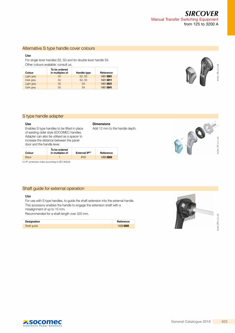
UseFor single lever handles S2, S3 and for double lever handle S4.Other colours available: consult us.
ColourTo be orderedin multiples of Handle type Reference
Light grey 50 S2, S3 1401 0001Dark grey 50 S2, S3 1401 0011Light grey 50 S4 1401 0031Dark grey 50 S4 1401 0041
S type handle adapter
acce
s_18
7_a_
1_ca
t
UseEnables S type handles to be fitted in place of existing older style SOCOMEC handles. Adapter can also be utilised as a spacer to increase the distance between the panel door and the handle lever.
DimensionsAdd 12 mm to the handle depth.
ColourTo be orderedin multiples of External IP(1) Reference
Black 1 IP65 1493 0000(1) IP: protection index according to IEC 60529.
Shaft guide for external operation
acce
s_26
0_a_
2_ca
t
UseFor use with S type handles, to guide the shaft extension into the external handle.This accessory enables the handle to engage the extension shaft with a misalignment of up to 15 mm.Recommended for a shaft length over 320 mm.
Designation Reference
Shaft guide 1429 0000
402 General Catalogue 2018
SIRCOVERManual Transfer Switching Equipmentfrom 125 to 3200 A
Accessories
External operation handle
acce
s_15
0_a_
2_ca
t
S2 type handle
acce
s_15
1_a_
1_ca
t
S3 type handle acce
s_15
2_a_
2_ca
t
S4 type handle
UseDoor interlocked external front operation handles include an escutcheon, are padlockable and must be utilised with an extension shaft.
SIRCOVER I-0-II and I-I+II-II
Rating (A) Frame size Switching typeExternal
IP(1)Handle
type Reference125 … 630 B3 … B5 I - 0 - II IP55 S2 1421 2113125 … 630 B3 … B5 I - 0 - II IP65 S2 1423 2113125 … 630 B3 … B5 I - I+II - II IP65 S2 1423 2114800 … 1600 B6 … B7 I - 0 - II IP65 S4 1443 3113(2)
800 … 1600 B6 … B7 I - I+II - II IP65 S4 1443 3114(2)
2000 … 3200 B8 I - 0 - II IP65 S5 1453 8113(2)
(1) IP: protection index according to IEC 60529.(2) Double lever handle.
SIRCOVER Bypass
Rating (A) Frame size Switching typeExternal
IP(1)Handle
type Reference125 … 200 B3 I - 0 - II IP55 S2 1421 2113125 … 200 B3 I - 0 - II IP65 S2 1423 2113250 … 630 B4 … B5 I - 0 - II IP65 S3 1433 3113800 … 1600 B6 … B7 I - 0 - II IP65 V2 4199 7146
(1) IP: protection index according to IEC 60529.
S5 type handle
acce
s_28
6_a_
1_ca
t
Direct operation handle
acce
s_12
9_b_
1_ca
t
acce
s_15
3_a_
2_ca
t
SIRCOVER BypassRating (A) Frame size Handle colour Handle type Reference125 … 200 B3 Blue J2 1122 1111250 … 630 B4 … B5 Black C1 2799 7052800 … 1600 B6 … B7 Black C2 2799 7012(1)
SIRCOVER I-0-II and I-I+II-IIRating (A) Frame size Handle colour Handle type Reference125 … 630 B3 … B5 Blue J2 1122 1111125 … 630 B3 … B5 Red J2 1123 1111800 … 1600 B6 … B7 Black C1 2799 70522000 … 3200 B8 Black S5 2799 7042(1)
acce
s_35
6_a_
1_ca
t
J2 type handle
(1) Double lever handle.
C1 type handle
C2 type handle
SIRCOVERManual Transfer Switching Equipment
from 125 to 3200 A
Alternative S type handle cover colours
acce
s_19
8_a_
2_ca
t
UseFor single lever handles S2, S3 and for double lever handle S4.Other colours available: consult us.
ColourTo be orderedin multiples of Handle type Reference
Light grey 50 S2, S3 1401 0001Dark grey 50 S2, S3 1401 0011Light grey 50 S4 1401 0031Dark grey 50 S4 1401 0041
S type handle adapter
acce
s_18
7_a_
1_ca
t
UseEnables S type handles to be fitted in place of existing older style SOCOMEC handles. Adapter can also be utilised as a spacer to increase the distance between the panel door and the handle lever.
DimensionsAdd 12 mm to the handle depth.
ColourTo be orderedin multiples of External IP(1) Reference
Black 1 IP65 1493 0000(1) IP: protection index according to IEC 60529.
Shaft guide for external operation
acce
s_26
0_a_
2_ca
t
UseFor use with S type handles, to guide the shaft extension into the external handle.This accessory enables the handle to engage the extension shaft with a misalignment of up to 15 mm.Recommended for a shaft length over 320 mm.
Designation Reference
Shaft guide 1429 0000
403General Catalogue 2018
SIRCOVERManual Transfer Switching Equipmentfrom 125 to 3200 A
Accessories (continued)Shaft for external operation
acce
s_36
9_a_
1_ca
tac
ces_
144_
b_1_
cat
X
acce
s_20
2_a_
1_X_
cat
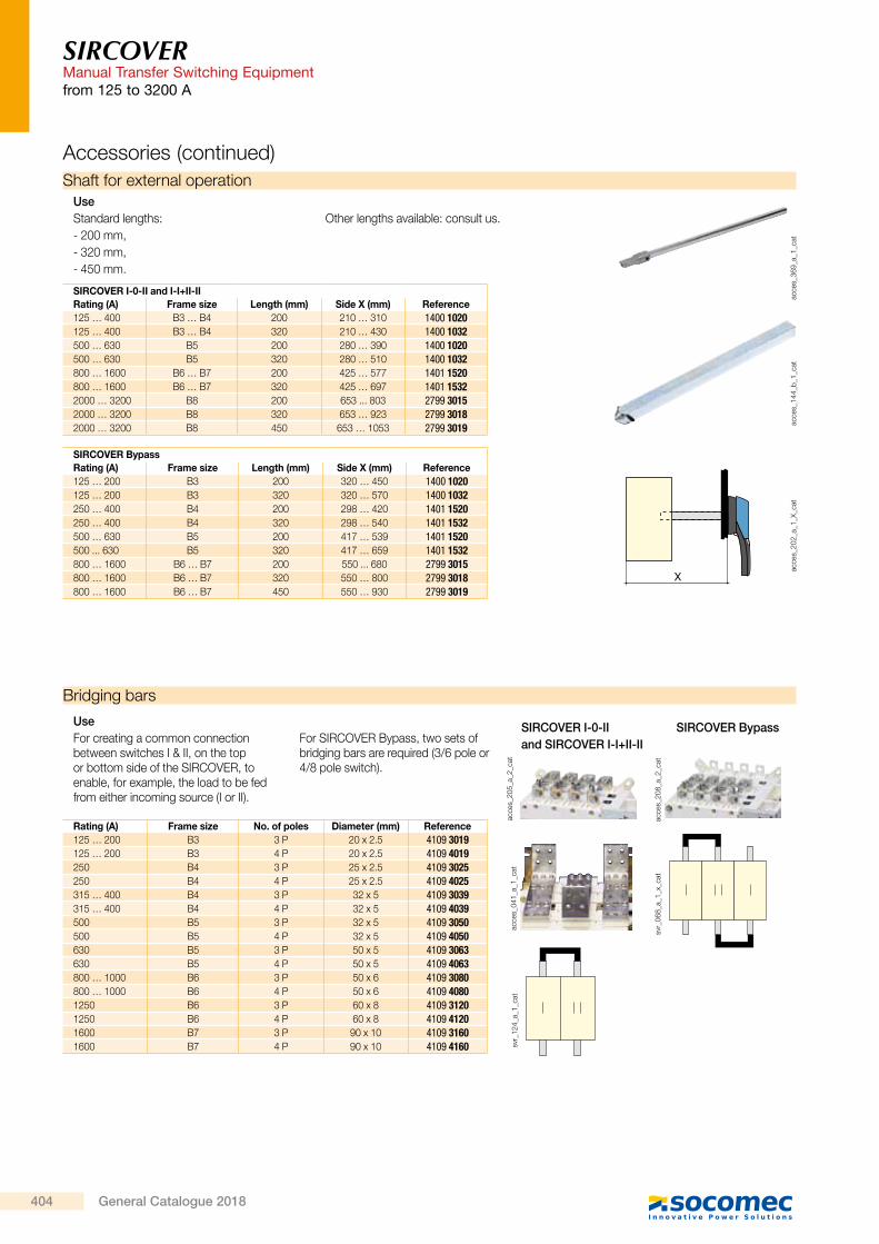
UseStandard lengths:- 200 mm,- 320 mm,- 450 mm.
Other lengths available: consult us.
SIRCOVER I-0-II and I-I+II-IIRating (A) Frame size Length (mm) Side X (mm) Reference125 … 400 B3 … B4 200 210 … 310 1400 1020125 … 400 B3 … B4 320 210 … 430 1400 1032500 … 630 B5 200 280 … 390 1400 1020500 … 630 B5 320 280 … 510 1400 1032800 … 1600 B6 … B7 200 425 … 577 1401 1520800 … 1600 B6 … B7 320 425 … 697 1401 15322000 … 3200 B8 200 653 ... 803 2799 30152000 … 3200 B8 320 653 … 923 2799 30182000 … 3200 B8 450 653 … 1053 2799 3019
SIRCOVER BypassRating (A) Frame size Length (mm) Side X (mm) Reference125 … 200 B3 200 320 … 450 1400 1020125 … 200 B3 320 320 … 570 1400 1032250 … 400 B4 200 298 … 420 1401 1520250 … 400 B4 320 298 … 540 1401 1532500 … 630 B5 200 417 … 539 1401 1520500 ... 630 B5 320 417 … 659 1401 1532800 … 1600 B6 … B7 200 550 ... 680 2799 3015800 … 1600 B6 … B7 320 550 … 800 2799 3018800 … 1600 B6 … B7 450 550 … 930 2799 3019
Bridging bars
acce
s_20
5_a_
2_ca
t
SIRCOVER I-0-IIand SIRCOVER I-I+II-II
acce
s_04
1_a_
1_ca
t
acce
s_20
8_a_
2_ca
t
SIRCOVER Bypass
svr_
068_
a_1_
x_ca
t
svr_
124_
a_1_
cat
UseFor creating a common connection between switches I & II, on the top or bottom side of the SIRCOVER, to enable, for example, the load to be fed from either incoming source (I or II).
For SIRCOVER Bypass, two sets of bridging bars are required (3/6 pole or 4/8 pole switch).
Rating (A) Frame size No. of poles Diameter (mm) Reference125 … 200 B3 3 P 20 x 2.5 4109 3019125 … 200 B3 4 P 20 x 2.5 4109 4019250 B4 3 P 25 x 2.5 4109 3025250 B4 4 P 25 x 2.5 4109 4025315 … 400 B4 3 P 32 x 5 4109 3039315 … 400 B4 4 P 32 x 5 4109 4039500 B5 3 P 32 x 5 4109 3050500 B5 4 P 32 x 5 4109 4050630 B5 3 P 50 x 5 4109 3063630 B5 4 P 50 x 5 4109 4063800 … 1000 B6 3 P 50 x 6 4109 3080800 … 1000 B6 4 P 50 x 6 4109 40801250 B6 3 P 60 x 8 4109 31201250 B6 4 P 60 x 8 4109 41201600 B7 3 P 90 x 10 4109 31601600 B7 4 P 90 x 10 4109 4160
SIRCOVERManual Transfer Switching Equipment
from 125 to 3200 A
Auxiliary contact
acce
s_06
5_a_
1_ca
tsv
r_05
8_a_
1_ca
t
UsePre-breaking and signalling of positions I and II: 1 to 2 NO/NC auxiliary contacts in each position.Low level AC: consult us.
Connection to the control circuitBy 6.35 mm fast-on terminal.Electrical characteristics30,000 operations.
Characteristics
NO/NC changeover contact
Rating (A) Frame size Contact(s) Reference
125 … 1600 B3 … B7 1st / 2nd 4109 00212000 … 3200 B8 1st / 2nd included
Nominal current (A)
Operating current Ie (A)
Rating (A) Frame size250 VACAC-13
400 VACAC-13
24 VDCDC-13
48 VDCDC-13
125 … 3200 B3... B8 16 12 8 14 6
Copper bar connection pieces
B
AA
acce
s_45
7_a_
1_x_
cat
Fig. 1
A
D
CC
acce
s_45
7_a_
1_x_
cat
Fig. 2
UseFor ratings 2000 to 3200 A.Enables:- Flat connection: the connection pieces
provide a link between the two power terminals of the same pole (Fig. 1).
- Edgewise connection: the connection pieces provide a link between the two power terminals of the same pole and an edgewise bar connection terminal.
- Top or bottom bridging between two poles (Fig. 3).
Once installed, the power terminal is connection ready.
For 3200 A rating, connection pieces (part A) are supplied as standard. Bolt sets must be ordered separately.
C
E
B
A
Fig. 3
acce
s_23
0_c_
1_x_
cat
Connection: the quantities given in the below table refer to the number of pieces required per pole, top or bottom.Bridging connection: the quantities given refer to the number of pieces required to complete a single bridging connection between two poles.
Reference
2000 – 2500 A 3200 A
Fig. 1 Fig. 2 Fig. 3 Fig. 1 Fig. 2 Fig. 3
Connection Bridging connection
I - II
Connection Bridging connection
I - IIFlat Edgewise Flat Edgewise
Connection - part A 2619 1200 1 1 2(2) included included included
Bolt kit 35 mm - part B 2699 1201 1(1) 2(2) 1(1) 2(2)
Bolt kit 45 mm - part B 2699 1200 1(1) 1(1)
T + Bolt kit - part C 2629 1200 1 1 1 1
Bracket + Bolt kit - part D 2639 1200 1 1
Bar + Bolt kit - part E 4109 0320 1 1
(1) Choose the bolt length according to the thickness of the bars being connected; if bar thickness is greater than 20 mm, 45 mm bolts are required.
(2) For bridging connections, quantity 2 pieces are required for creating the link between the two power terminals of the same pole for switch bodies I and II.
The quantities of the applicable pieces then need to be multiplied by the number of connection points (power terminals) in order to determine the total quantity required of each part.Example: for a 4 pole 2500 A SIRCOVER with upstream edgewise connection (Fig. 2) and downstream bridging (Fig. 3), the following quantities will be required:
Part Upstream edgewise quantity Downstream bridging quantity Total quantity
A 8 8 16
B 0 8 8
C 8 4 12
D 8 0 8
E 0 4 4
(1) Single pole connection: 1 pole (top or bottom) comprises two power terminals which are to be linked with the copper connection kit.
(1)
404 General Catalogue 2018

SIRCOVERManual Transfer Switching Equipmentfrom 125 to 3200 A
Accessories (continued)Shaft for external operation
acce
s_36
9_a_
1_ca
tac
ces_
144_
b_1_
cat
X
acce
s_20
2_a_
1_X_
cat
UseStandard lengths:- 200 mm,- 320 mm,- 450 mm.
Other lengths available: consult us.
SIRCOVER I-0-II and I-I+II-IIRating (A) Frame size Length (mm) Side X (mm) Reference125 … 400 B3 … B4 200 210 … 310 1400 1020125 … 400 B3 … B4 320 210 … 430 1400 1032500 … 630 B5 200 280 … 390 1400 1020500 … 630 B5 320 280 … 510 1400 1032800 … 1600 B6 … B7 200 425 … 577 1401 1520800 … 1600 B6 … B7 320 425 … 697 1401 15322000 … 3200 B8 200 653 ... 803 2799 30152000 … 3200 B8 320 653 … 923 2799 30182000 … 3200 B8 450 653 … 1053 2799 3019
SIRCOVER BypassRating (A) Frame size Length (mm) Side X (mm) Reference125 … 200 B3 200 320 … 450 1400 1020125 … 200 B3 320 320 … 570 1400 1032250 … 400 B4 200 298 … 420 1401 1520250 … 400 B4 320 298 … 540 1401 1532500 … 630 B5 200 417 … 539 1401 1520500 ... 630 B5 320 417 … 659 1401 1532800 … 1600 B6 … B7 200 550 ... 680 2799 3015800 … 1600 B6 … B7 320 550 … 800 2799 3018800 … 1600 B6 … B7 450 550 … 930 2799 3019
Bridging bars
acce
s_20
5_a_
2_ca
t
SIRCOVER I-0-IIand SIRCOVER I-I+II-II
acce
s_04
1_a_
1_ca
t
acce
s_20
8_a_
2_ca
t
SIRCOVER Bypass
svr_
068_
a_1_
x_ca
t
svr_
124_
a_1_
cat
UseFor creating a common connection between switches I & II, on the top or bottom side of the SIRCOVER, to enable, for example, the load to be fed from either incoming source (I or II).
For SIRCOVER Bypass, two sets of bridging bars are required (3/6 pole or 4/8 pole switch).
Rating (A) Frame size No. of poles Diameter (mm) Reference125 … 200 B3 3 P 20 x 2.5 4109 3019125 … 200 B3 4 P 20 x 2.5 4109 4019250 B4 3 P 25 x 2.5 4109 3025250 B4 4 P 25 x 2.5 4109 4025315 … 400 B4 3 P 32 x 5 4109 3039315 … 400 B4 4 P 32 x 5 4109 4039500 B5 3 P 32 x 5 4109 3050500 B5 4 P 32 x 5 4109 4050630 B5 3 P 50 x 5 4109 3063630 B5 4 P 50 x 5 4109 4063800 … 1000 B6 3 P 50 x 6 4109 3080800 … 1000 B6 4 P 50 x 6 4109 40801250 B6 3 P 60 x 8 4109 31201250 B6 4 P 60 x 8 4109 41201600 B7 3 P 90 x 10 4109 31601600 B7 4 P 90 x 10 4109 4160
SIRCOVERManual Transfer Switching Equipment
from 125 to 3200 A
Auxiliary contact
acce
s_06
5_a_
1_ca
tsv
r_05
8_a_
1_ca
t
UsePre-breaking and signalling of positions I and II: 1 to 2 NO/NC auxiliary contacts in each position.Low level AC: consult us.
Connection to the control circuitBy 6.35 mm fast-on terminal.Electrical characteristics30,000 operations.
Characteristics
NO/NC changeover contact
Rating (A) Frame size Contact(s) Reference
125 … 1600 B3 … B7 1st / 2nd 4109 00212000 … 3200 B8 1st / 2nd included
Nominal current (A)
Operating current Ie (A)
Rating (A) Frame size250 VACAC-13
400 VACAC-13
24 VDCDC-13
48 VDCDC-13
125 … 3200 B3... B8 16 12 8 14 6
Copper bar connection pieces
B
AA
acce
s_45
7_a_
1_x_
cat
Fig. 1
A
D
CC
acce
s_45
7_a_
1_x_
cat
Fig. 2
UseFor ratings 2000 to 3200 A.Enables:- Flat connection: the connection pieces
provide a link between the two power terminals of the same pole (Fig. 1).
- Edgewise connection: the connection pieces provide a link between the two power terminals of the same pole and an edgewise bar connection terminal.
- Top or bottom bridging between two poles (Fig. 3).
Once installed, the power terminal is connection ready.
For 3200 A rating, connection pieces (part A) are supplied as standard. Bolt sets must be ordered separately.
C
E
B
A
Fig. 3
acce
s_23
0_c_
1_x_
cat
Connection: the quantities given in the below table refer to the number of pieces required per pole, top or bottom.Bridging connection: the quantities given refer to the number of pieces required to complete a single bridging connection between two poles.
Reference
2000 – 2500 A 3200 A
Fig. 1 Fig. 2 Fig. 3 Fig. 1 Fig. 2 Fig. 3
Connection Bridging connection
I - II
Connection Bridging connection
I - IIFlat Edgewise Flat Edgewise
Connection - part A 2619 1200 1 1 2(2) included included included
Bolt kit 35 mm - part B 2699 1201 1(1) 2(2) 1(1) 2(2)
Bolt kit 45 mm - part B 2699 1200 1(1) 1(1)
T + Bolt kit - part C 2629 1200 1 1 1 1
Bracket + Bolt kit - part D 2639 1200 1 1
Bar + Bolt kit - part E 4109 0320 1 1
(1) Choose the bolt length according to the thickness of the bars being connected; if bar thickness is greater than 20 mm, 45 mm bolts are required.
(2) For bridging connections, quantity 2 pieces are required for creating the link between the two power terminals of the same pole for switch bodies I and II.
The quantities of the applicable pieces then need to be multiplied by the number of connection points (power terminals) in order to determine the total quantity required of each part.Example: for a 4 pole 2500 A SIRCOVER with upstream edgewise connection (Fig. 2) and downstream bridging (Fig. 3), the following quantities will be required:
Part Upstream edgewise quantity Downstream bridging quantity Total quantity
A 8 8 16
B 0 8 8
C 8 4 12
D 8 0 8
E 0 4 4
(1) Single pole connection: 1 pole (top or bottom) comprises two power terminals which are to be linked with the copper connection kit.
(1)
405General Catalogue 2018

SIRCOVERManual Transfer Switching Equipmentfrom 125 to 3200 A
Terminal shrouds
acce
s_20
6_a_
2_ca
t
UseProtection against direct contact with terminals or connecting parts.
AdvantagePerforations allow remote thermographic inspection without the need to remove the shrouds.
Rating (A) Frame sizeNo. of poles Position Reference
125 … 200 B3 3 P top / bottom / front (I) / rear (II) 2694 3014(1)(2)
125 … 200 B3 4 P top / bottom / front (I) / rear (II) 2694 4014(1)(2)
250 … 400 B4 3 P top / bottom / front (I) / rear (II) 2694 3021(1)(2)
250 … 400 B4 4 P top / bottom / front (I) / rear (II) 2694 4021(1)(2)
500 … 630 B5 3 P top / bottom / front (I) / rear (II) 2694 3051(1)(2)
500 … 630 B5 4 P top / bottom / front (I) / rear (II) 2694 4051(1)(2)
(1) For complete shrouding at front, rear, top and bottom, order 4 x for a SIRCOVER and 6 x for a SIRCOVER Bypass; if equipped with bridging bars order 3 x for a SIRCOVER and 4 x for a SIRCOVER Bypass.
(2) For top and bottom shrouding for the front only, order 2 x for a SIRCOVER and a SIRCOVER Bypass.
Terminal screens
acce
s_20
7_a_
2_ca
t
UseUpstream and downstream protection against direct contact with terminals or connection parts. For upstream and downstream protection, order quantity 1.
Rating (A) Frame size No. of poles Position Reference
125 … 200 B3 3 P top / bottom 1509 3012125 … 200 B3 4 P top / bottom 1509 4012250 … 400 B4 3 P top / bottom 1509 3025250 … 400 B4 4 P top / bottom 1509 4025500 … 630 B5 3 P top / bottom 1509 3063500 … 630 B5 4 P top / bottom 1509 4063800 … 1250 B6 3 P top / bottom 1509 3080800 … 1250 B6 4 P top / bottom 1509 40801600 B7 3 P top / bottom 1509 31601600 B7 4 P top / bottom 1509 41602000 … 3200 B8 3 / 4 P top / bottom included
Inter-phase barrier
UseSafe isolation between the terminals, essential for use at 690 VAC or in a polluted or dusty atmosphere.
Rating (A) Frame size No. of poles Reference
125 … 200 B3 3 P 2998 0033125 … 200 B3 4 P 2998 0034250 … 400 B4 3 P 2998 0023250 … 400 B4 4 P 2998 0024500 … 630 B5 3 P 2998 0013500 … 630 B5 4 P 2998 0014800 … 3200 B6 … B8 3/4 P included
Accessories (continued)
SIRCOVERManual Transfer Switching Equipment
from 125 to 3200 A
Other specific accessoriesbd
_03_
04_0
1
• Customised protection screens (for specific dimensions or high ambient temperatures). • Connection accessories. • Low level auxiliary contacts.
Key handle interlocking system
acce
s_06
1_a_
1_x_
cat
Fig. 1
acce
s_00
1_a_
1_x_
cat
Fig. 2
acce
s_13
2_a_
1_x_
cat
Fig. 3
acce
s_15
8_a_
1_x_
cat
Fig. 4
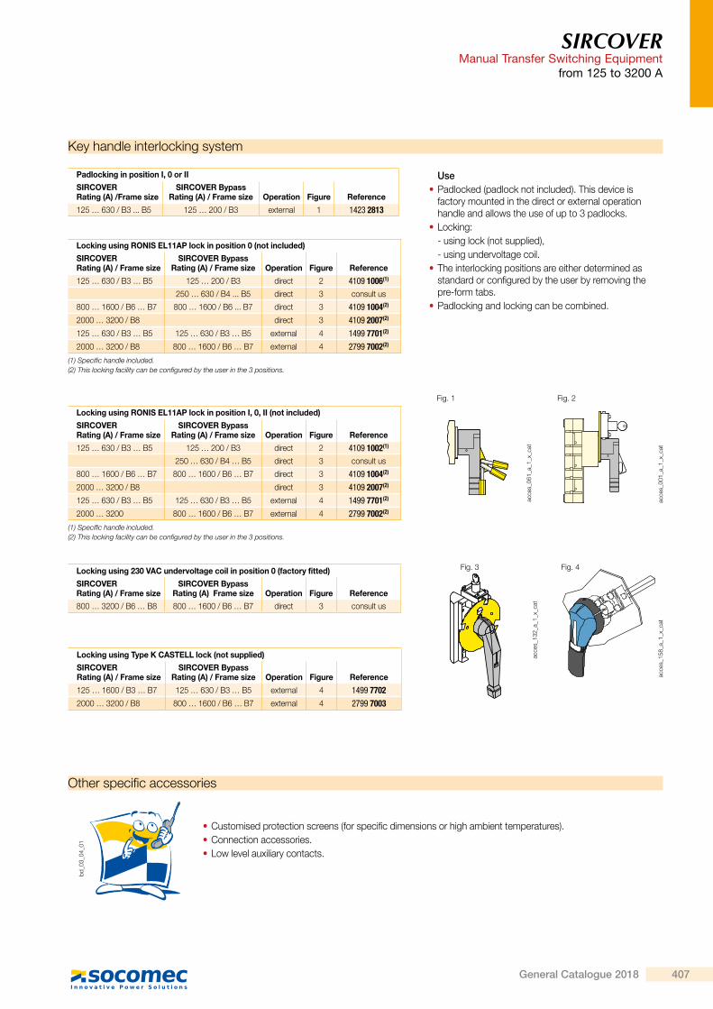
Use • Padlocked (padlock not included). This device is factory mounted in the direct or external operation handle and allows the use of up to 3 padlocks.
• Locking:- using lock (not supplied),- using undervoltage coil.
• The interlocking positions are either determined as standard or configured by the user by removing the pre-form tabs.
• Padlocking and locking can be combined.
Padlocking in position I, 0 or II
SIRCOVERRating (A) /Frame size
SIRCOVER BypassRating (A) / Frame size Operation Figure Reference
125 … 630 / B3 ... B5 125 … 200 / B3 external 1 1423 2813
Locking using RONIS EL11AP lock in position 0 (not included)
SIRCOVERRating (A) / Frame size
SIRCOVER Bypass Rating (A) / Frame size Operation Figure Reference
125 … 630 / B3 … B5 125 … 200 / B3 direct 2 4109 1006(1)
250 … 630 / B4 ... B5 direct 3 consult us
800 … 1600 / B6 … B7 800 … 1600 / B6 ... B7 direct 3 4109 1004(2)
2000 … 3200 / B8 direct 3 4109 2007(2)
125 … 630 / B3 … B5 125 … 630 / B3 … B5 external 4 1499 7701(2)
2000 … 3200 / B8 800 … 1600 / B6 … B7 external 4 2799 7002(2)
(1) Specific handle included.(2) This locking facility can be configured by the user in the 3 positions.
Locking using RONIS EL11AP lock in position I, 0, II (not included)
SIRCOVERRating (A) / Frame size
SIRCOVER BypassRating (A) / Frame size Operation Figure Reference
125 … 630 / B3 … B5 125 … 200 / B3 direct 2 4109 1002(1)
250 … 630 / B4 … B5 direct 3 consult us
800 … 1600 / B6 … B7 800 … 1600 / B6 … B7 direct 3 4109 1004(2)
2000 … 3200 / B8 direct 3 4109 2007(2)
125 … 630 / B3 … B5 125 … 630 / B3 … B5 external 4 1499 7701(2)
2000 … 3200 800 … 1600 / B6 … B7 external 4 2799 7002(2)
(1) Specific handle included.(2) This locking facility can be configured by the user in the 3 positions.
Locking using 230 VAC undervoltage coil in position 0 (factory fitted)
SIRCOVERRating (A) / Frame size
SIRCOVER BypassRating (A) Frame size Operation Figure Reference
800 … 3200 / B6 … B8 800 … 1600 / B6 … B7 direct 3 consult us
Locking using Type K CASTELL lock (not supplied)
SIRCOVER Rating (A) / Frame size
SIRCOVER Bypass Rating (A) / Frame size Operation Figure Reference
125 … 1600 / B3 … B7 125 … 630 / B3 … B5 external 4 1499 77022000 … 3200 / B8 800 … 1600 / B6 … B7 external 4 2799 7003
406 General Catalogue 2018
SIRCOVERManual Transfer Switching Equipmentfrom 125 to 3200 A
Terminal shrouds
acce
s_20
6_a_
2_ca
t
UseProtection against direct contact with terminals or connecting parts.
AdvantagePerforations allow remote thermographic inspection without the need to remove the shrouds.
Rating (A) Frame sizeNo. of poles Position Reference
125 … 200 B3 3 P top / bottom / front (I) / rear (II) 2694 3014(1)(2)
125 … 200 B3 4 P top / bottom / front (I) / rear (II) 2694 4014(1)(2)
250 … 400 B4 3 P top / bottom / front (I) / rear (II) 2694 3021(1)(2)
250 … 400 B4 4 P top / bottom / front (I) / rear (II) 2694 4021(1)(2)
500 … 630 B5 3 P top / bottom / front (I) / rear (II) 2694 3051(1)(2)
500 … 630 B5 4 P top / bottom / front (I) / rear (II) 2694 4051(1)(2)
(1) For complete shrouding at front, rear, top and bottom, order 4 x for a SIRCOVER and 6 x for a SIRCOVER Bypass; if equipped with bridging bars order 3 x for a SIRCOVER and 4 x for a SIRCOVER Bypass.
(2) For top and bottom shrouding for the front only, order 2 x for a SIRCOVER and a SIRCOVER Bypass.
Terminal screens
acce
s_20
7_a_
2_ca
t
UseUpstream and downstream protection against direct contact with terminals or connection parts. For upstream and downstream protection, order quantity 1.
Rating (A) Frame size No. of poles Position Reference
125 … 200 B3 3 P top / bottom 1509 3012125 … 200 B3 4 P top / bottom 1509 4012250 … 400 B4 3 P top / bottom 1509 3025250 … 400 B4 4 P top / bottom 1509 4025500 … 630 B5 3 P top / bottom 1509 3063500 … 630 B5 4 P top / bottom 1509 4063800 … 1250 B6 3 P top / bottom 1509 3080800 … 1250 B6 4 P top / bottom 1509 40801600 B7 3 P top / bottom 1509 31601600 B7 4 P top / bottom 1509 41602000 … 3200 B8 3 / 4 P top / bottom included
Inter-phase barrier
UseSafe isolation between the terminals, essential for use at 690 VAC or in a polluted or dusty atmosphere.
Rating (A) Frame size No. of poles Reference
125 … 200 B3 3 P 2998 0033125 … 200 B3 4 P 2998 0034250 … 400 B4 3 P 2998 0023250 … 400 B4 4 P 2998 0024500 … 630 B5 3 P 2998 0013500 … 630 B5 4 P 2998 0014800 … 3200 B6 … B8 3/4 P included
Accessories (continued)
SIRCOVERManual Transfer Switching Equipment
from 125 to 3200 A
Other specific accessories
bd_0
3_04
_01
• Customised protection screens (for specific dimensions or high ambient temperatures). • Connection accessories. • Low level auxiliary contacts.
Key handle interlocking system
acce
s_06
1_a_
1_x_
cat
Fig. 1
acce
s_00
1_a_
1_x_
cat
Fig. 2
acce
s_13
2_a_
1_x_
cat
Fig. 3
acce
s_15
8_a_
1_x_
cat
Fig. 4
Use • Padlocked (padlock not included). This device is factory mounted in the direct or external operation handle and allows the use of up to 3 padlocks.
• Locking:- using lock (not supplied),- using undervoltage coil.
• The interlocking positions are either determined as standard or configured by the user by removing the pre-form tabs.
• Padlocking and locking can be combined.
Padlocking in position I, 0 or II
SIRCOVERRating (A) /Frame size
SIRCOVER BypassRating (A) / Frame size Operation Figure Reference
125 … 630 / B3 ... B5 125 … 200 / B3 external 1 1423 2813
Locking using RONIS EL11AP lock in position 0 (not included)
SIRCOVERRating (A) / Frame size
SIRCOVER Bypass Rating (A) / Frame size Operation Figure Reference
125 … 630 / B3 … B5 125 … 200 / B3 direct 2 4109 1006(1)
250 … 630 / B4 ... B5 direct 3 consult us
800 … 1600 / B6 … B7 800 … 1600 / B6 ... B7 direct 3 4109 1004(2)
2000 … 3200 / B8 direct 3 4109 2007(2)
125 … 630 / B3 … B5 125 … 630 / B3 … B5 external 4 1499 7701(2)
2000 … 3200 / B8 800 … 1600 / B6 … B7 external 4 2799 7002(2)
(1) Specific handle included.(2) This locking facility can be configured by the user in the 3 positions.
Locking using RONIS EL11AP lock in position I, 0, II (not included)
SIRCOVERRating (A) / Frame size
SIRCOVER BypassRating (A) / Frame size Operation Figure Reference
125 … 630 / B3 … B5 125 … 200 / B3 direct 2 4109 1002(1)
250 … 630 / B4 … B5 direct 3 consult us
800 … 1600 / B6 … B7 800 … 1600 / B6 … B7 direct 3 4109 1004(2)
2000 … 3200 / B8 direct 3 4109 2007(2)
125 … 630 / B3 … B5 125 … 630 / B3 … B5 external 4 1499 7701(2)
2000 … 3200 800 … 1600 / B6 … B7 external 4 2799 7002(2)
(1) Specific handle included.(2) This locking facility can be configured by the user in the 3 positions.
Locking using 230 VAC undervoltage coil in position 0 (factory fitted)
SIRCOVERRating (A) / Frame size
SIRCOVER BypassRating (A) Frame size Operation Figure Reference
800 … 3200 / B6 … B8 800 … 1600 / B6 … B7 direct 3 consult us
Locking using Type K CASTELL lock (not supplied)
SIRCOVER Rating (A) / Frame size
SIRCOVER Bypass Rating (A) / Frame size Operation Figure Reference
125 … 1600 / B3 … B7 125 … 630 / B3 … B5 external 4 1499 77022000 … 3200 / B8 800 … 1600 / B6 … B7 external 4 2799 7003
407General Catalogue 2018

SIRCOVERManual Transfer Switching Equipmentfrom 125 to 3200 A
Polyester enclosed solution
• Adapted to chemical attack, dust hazard, contamination hazard and atmospheric corrosion.
• Operating handle: S type black handle padlockable in position 0.
• Protection degree: IP55 / IK 10. • Colour: RAL 7030 (rating < 400 A), RAL 9002 (rating ≥ 400 A).
• Cable gland plate: none.
• Material: glass fibre reinforced polyester. • Coating: none. • Wall mounting: 4 mounting brackets supplied (not fitted).
• Locking device: screw (rating < 400 A), 3 mm double bar key (rating ≥ 400 A), key supplied.
• Miscellaneous: high resistance to chemicals, self-extinguishable at 960°C, 3 bolted earth connection points.
General characteristics
coff_
299_
a_1_
cat
References
Rating (A) No. of poles
Top/bottom connectionI - 0 - II
Reference125 3 P 4215 3012125 4 P 4215 4012160 3 P 4215 3016160 4 P 4215 4016250 3 P 4215 3025250 4 P 4215 4025400 3 P 4215 3040400 4 P 4215 4040630 3 P 4215 3063630 4 P 4215 4063
Dimensions
HN
B1Ah
W
M
D (1)
Z
coff_
121_
h_1_
gb_c
at
(1) 125 … 630 A : 45 mm
Rating (A) No. of poles H x W x D (mm)Max. connection
cross-section (mm2) M (mm) N (mm) Z (mm)
Top/bottom connection
Ah (mm) B1 (mm) Weight (kg)
125 3 P 540 x 270 x 233 50 272 542 28 210 210 9
125 4 P 540 x 360 x 233 50 362 542 28 210 210 10
160 3 P 540 x 270 x 233 95 272 542 28 210 210 9
160 4 P 540 x 360 x 233 95 362 542 28 210 210 10
250 3 P 540 x 360 x 233 150 362 542 29 205 205 11
250 4 P 540 x 360 x 233 150 362 542 29 205 205 12
400 3 P 800 x 600 x 300 240 620 796 29 330 330 30
400 4 P 800 x 600 x 300 240 620 796 29 330 330 31
630 3 P 800 x 600 x 300 2 x 300 620 796 45 297 297 38
630 4 P 800 x 600 x 300 2 x 300 620 796 45 297 297 40
SIRCOVERManual Transfer Switching Equipment
from 125 to 3200 A
Steel enclosed solutionGeneral characteristics
References
Rating (A) No. of poles
Top/bottom connection I - 0 - II
Reference125 3 P 4212 3012125 4 P 4212 4012160 3 P 4212 3016160 4 P 4212 4016250 3 P 4212 3025250 4 P 4212 4025400 3 P 4212 3040400 4 P 4212 4040500 3 P 4212 3050500 4 P 4212 4050630 3 P 4212 3063630 4 P 4212 4063800 3 P 4212 3080800 4 P 4212 40801250 3 P 4212 31201250 4 P 4212 41201600 3 P 4212 31601600 4 P 4212 4160
Dimensions
D
H N
WM
AhB1
Z
(1)
coff_
318_
a_1_
gb_c
at
(1) 125 … 630 A : 58 mm 800 … 1 600 A : 74 mm.
Rating (A) No. of poles H x W x D (mm)Max. connection
cross-section (mm2) M (mm) N (mm) Z (mm)
Top/bottom connection
Ah (mm) B1 (mm) Weight (kg)
125 3/4 P 500 x 400 x 250 50 448 458 28 190 190 23
160 3/4 P 500 x 400 x 250 95 448 458 28 190 190 23
250 3/4 P 500 x 400 x 250 150 448 458 29.3 185 185 23
400 3/4 P 800 x 600 x 300 240 758 552 29.3 330 330 45
500 3/4 P 800 x 600 x 300 240 648 658 45 298 298 55
630 3/4 P 800 x 600 x 300 2 x 300 648 658 45 290 290 55
800 3/4 P 1200 x 700 x 500 2 x 300 740 1152 156 465 465 78
1,250 3/4 P 1200 x 700 x 500 4 x 185 740 1152 156 465 465 88
1,600 3/4 P 1200 x 700 x 500 4 x 300 740 1152 156 470 470 94
• Adapted to mechanical risk and dust hazard.
• Operating handle: S type black handle padlockable in position 0.
• Protection degree: IP54 • Colour: RAL 7035 up to 630 A, or RAL 7035 apart from casing and door RAL 9001.
• Cable gland plates: top and bottom. • Material: XC steel, thickness 1.5 mm. • Coating: epoxy polyester powder (≤ 630 A), polyester powder (≥ 800 A).
• Mounting: 4 wall mounting brackets - not fitted.
• Door: solid with hinges.
• Locking device: 3 mm double bar key (≤ 630 A), 8 mm spanner key (≥ 800 A), key supplied.
• Miscellaneous: multiple earth connection points, double door locking.
coff_
298_
b
408 General Catalogue 2018

SIRCOVERManual Transfer Switching Equipmentfrom 125 to 3200 A
Polyester enclosed solution
• Adapted to chemical attack, dust hazard, contamination hazard and atmospheric corrosion.
• Operating handle: S type black handle padlockable in position 0.
• Protection degree: IP55 / IK 10. • Colour: RAL 7030 (rating < 400 A), RAL 9002 (rating ≥ 400 A).
• Cable gland plate: none.
• Material: glass fibre reinforced polyester. • Coating: none. • Wall mounting: 4 mounting brackets supplied (not fitted).
• Locking device: screw (rating < 400 A), 3 mm double bar key (rating ≥ 400 A), key supplied.
• Miscellaneous: high resistance to chemicals, self-extinguishable at 960°C, 3 bolted earth connection points.
General characteristics
coff_
299_
a_1_
cat
References
Rating (A) No. of poles
Top/bottom connectionI - 0 - II
Reference125 3 P 4215 3012125 4 P 4215 4012160 3 P 4215 3016160 4 P 4215 4016250 3 P 4215 3025250 4 P 4215 4025400 3 P 4215 3040400 4 P 4215 4040630 3 P 4215 3063630 4 P 4215 4063
Dimensions
HN
B1Ah
W
M
D (1)
Z
coff_
121_
h_1_
gb_c
at
(1) 125 … 630 A : 45 mm
Rating (A) No. of poles H x W x D (mm)Max. connection
cross-section (mm2) M (mm) N (mm) Z (mm)
Top/bottom connection
Ah (mm) B1 (mm) Weight (kg)
125 3 P 540 x 270 x 233 50 272 542 28 210 210 9
125 4 P 540 x 360 x 233 50 362 542 28 210 210 10
160 3 P 540 x 270 x 233 95 272 542 28 210 210 9
160 4 P 540 x 360 x 233 95 362 542 28 210 210 10
250 3 P 540 x 360 x 233 150 362 542 29 205 205 11
250 4 P 540 x 360 x 233 150 362 542 29 205 205 12
400 3 P 800 x 600 x 300 240 620 796 29 330 330 30
400 4 P 800 x 600 x 300 240 620 796 29 330 330 31
630 3 P 800 x 600 x 300 2 x 300 620 796 45 297 297 38
630 4 P 800 x 600 x 300 2 x 300 620 796 45 297 297 40
SIRCOVERManual Transfer Switching Equipment
from 125 to 3200 A
Steel enclosed solutionGeneral characteristics
References
Rating (A) No. of poles
Top/bottom connection I - 0 - II
Reference125 3 P 4212 3012125 4 P 4212 4012160 3 P 4212 3016160 4 P 4212 4016250 3 P 4212 3025250 4 P 4212 4025400 3 P 4212 3040400 4 P 4212 4040500 3 P 4212 3050500 4 P 4212 4050630 3 P 4212 3063630 4 P 4212 4063800 3 P 4212 3080800 4 P 4212 40801250 3 P 4212 31201250 4 P 4212 41201600 3 P 4212 31601600 4 P 4212 4160
Dimensions
D
H N
WM
AhB1
Z
(1)
coff_
318_
a_1_
gb_c
at
(1) 125 … 630 A : 58 mm 800 … 1 600 A : 74 mm.
Rating (A) No. of poles H x W x D (mm)Max. connection
cross-section (mm2) M (mm) N (mm) Z (mm)
Top/bottom connection
Ah (mm) B1 (mm) Weight (kg)
125 3/4 P 500 x 400 x 250 50 448 458 28 190 190 23
160 3/4 P 500 x 400 x 250 95 448 458 28 190 190 23
250 3/4 P 500 x 400 x 250 150 448 458 29.3 185 185 23
400 3/4 P 800 x 600 x 300 240 758 552 29.3 330 330 45
500 3/4 P 800 x 600 x 300 240 648 658 45 298 298 55
630 3/4 P 800 x 600 x 300 2 x 300 648 658 45 290 290 55
800 3/4 P 1200 x 700 x 500 2 x 300 740 1152 156 465 465 78
1,250 3/4 P 1200 x 700 x 500 4 x 185 740 1152 156 465 465 88
1,600 3/4 P 1200 x 700 x 500 4 x 300 740 1152 156 470 470 94
• Adapted to mechanical risk and dust hazard.
• Operating handle: S type black handle padlockable in position 0.
• Protection degree: IP54 • Colour: RAL 7035 up to 630 A, or RAL 7035 apart from casing and door RAL 9001.
• Cable gland plates: top and bottom. • Material: XC steel, thickness 1.5 mm. • Coating: epoxy polyester powder (≤ 630 A), polyester powder (≥ 800 A).
• Mounting: 4 wall mounting brackets - not fitted.
• Door: solid with hinges.
• Locking device: 3 mm double bar key (≤ 630 A), 8 mm spanner key (≥ 800 A), key supplied.
• Miscellaneous: multiple earth connection points, double door locking.
coff_
298_
b
409General Catalogue 2018
SIRCOVERManual Transfer Switching Equipmentfrom 125 to 3200 A
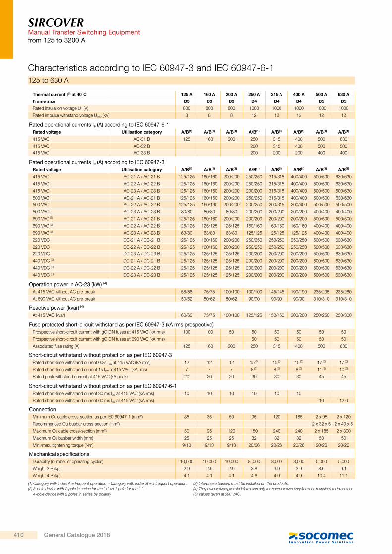
Characteristics according to IEC 60947-3 and IEC 60947-6-1125 to 630 A
Thermal current Ith at 40°C 125 A 160 A 200 A 250 A 315 A 400 A 500 A 630 A
Frame size B3 B3 B3 B4 B4 B4 B5 B5
Rated insulation voltage Ui (V) 800 800 800 1000 1000 1000 1000 1000
Rated impulse withstand voltage Uimp (kV) 8 8 8 12 12 12 12 12
Rated operational currents Ie (A) according to IEC 60947-6-1Rated voltage Utilisation category A/B(1) A/B(1) A/B(1) A/B(1) A/B(1) A/B(1) A/B(1) A/B(1)
415 VAC AC-31 B 125 160 200 250 315 400 500 630
415 VAC AC-32 B 200 315 400 500 500
415 VAC AC-33 B 200 200 200 400 400
Rated operational currents Ie (A) according to IEC 60947-3Rated voltage Utilisation category A/B(1) A/B(1) A/B(1) A/B(1) A/B(1) A/B(1) A/B(1) A/B(1)
415 VAC AC-21 A / AC-21 B 125/125 160/160 200/200 250/250 315/315 400/400 500/500 630/630
415 VAC AC-22 A / AC-22 B 125/125 160/160 200/200 250/250 315/315 400/400 500/500 630/630
415 VAC AC-23 A / AC-23 B 125/125 160/160 200/200 200/200 315/315 400/400 500/500 500/630
500 VAC AC-21 A / AC-21 B 125/125 160/160 200/200 250/250 315/315 400/400 500/500 630/630
500 VAC AC-22 A / AC-22 B 125/125 160/160 200/200 200/250 200/315 200/400 500/500 500/500
500 VAC AC-23 A / AC-23 B 80/80 80/80 80/80 200/200 200/200 200/200 400/400 400/400
690 VAC (3) AC-21 A / AC-21 B 125/125 160/160 200/200 200/200 200/200 200/200 500/500 500/500
690 VAC (3) AC-22 A / AC-22 B 125/125 125/125 125/125 160/160 160/160 160/160 400/400 400/400
690 VAC (3) AC-23 A / AC-23 B 63/80 63/80 63/80 125/125 125/125 125/125 400/400 400/400
220 VDC DC-21 A / DC-21 B 125/125 160/160 200/200 250/250 250/250 250/250 500/500 630/630
220 VDC DC-22 A / DC-22 B 125/125 160/160 200/200 250/250 250/250 250/250 500/500 630/630
220 VDC DC-23 A / DC-23 B 125/125 125/125 125/125 200/200 200/200 200/200 500/500 630/630
440 VDC (2) DC-21 A / DC-21 B 125/125 125/125 125/125 200/200 200/200 200/200 500/500 630/630
440 VDC (2) DC-22 A / DC-22 B 125/125 125/125 125/125 200/200 200/200 200/200 500/500 630/630
440 VDC (2) DC-23 A / DC-23 B 125/125 125/125 125/125 200/200 200/200 200/200 500/500 630/630
Operation power in AC-23 (kW) (4)
At 415 VAC without AC pre-break 58/58 75/75 100/100 100/100 145/145 190/190 235/235 235/280
At 690 VAC without AC pre-break 50/62 50/62 50/62 90/90 90/90 90/90 310/310 310/310
Reactive power (kvar) (4)
At 415 VAC (kvar) 60/60 75/75 100/100 125/125 150/150 200/200 250/250 250/300
Fuse protected short-circuit withstand as per IEC 60947-3 (kA rms prospective)Prospective short-circuit current with gG DIN fuses at 415 VAC (kA rms) 100 100 50 50 50 50 50 50
Prospective short-circuit current with gG DIN fuses at 690 VAC (kA rms) 50 50 50 50 50
Associated fuse rating (A) 125 160 200 250 315 400 500 630
Short-circuit withstand without protection as per IEC 60947-3Rated short-time withstand current 0.3s Icw at 415 VAC (kA rms) 12 12 12 15 (5) 15 (5) 15 (5) 17 (5) 17 (5)
Rated short-time withstand current 1s Icw at 415 VAC (kA rms) 7 7 7 8 (5) 8 (5) 8 (5) 11 (5) 10 (5)
Rated peak withstand current at 415 VAC (kA peak) 20 20 20 30 30 30 45 45
Short-circuit withstand without protection as per IEC 60947-6-1Rated short-time withstand current 30 ms Icw at 415 VAC (kA rms) 10 10 10 10 10 10
Rated short-time withstand current 60 ms Icw at 415 VAC (kA rms) 10 12.6
ConnectionMinimum Cu cable cross-section as per IEC 60947-1 (mm²) 35 35 50 95 120 185 2 x 95 2 x 120
Recommended Cu busbar cross-section (mm²) 2 x 32 x 5 2 x 40 x 5
Maximum Cu cable cross-section (mm²) 50 95 120 150 240 240 2 x 185 2 x 300
Maximum Cu busbar width (mm) 25 25 25 32 32 32 50 50
Min./max. tightening torque (Nm) 9/13 9/13 9/13 20/26 20/26 20/26 20/26 20/26
Mechanical specificationsDurability (number of operating cycles) 10,000 10,000 10,000 8 ,000 8,000 8,000 5,000 5,000
Weight 3 P (kg) 2.9 2.9 2.9 3.8 3.9 3.9 8.6 9.1
Weight 4 P (kg) 4.1 4.1 4.1 4.6 4.9 4.9 10.4 11.1
(1) Category with index A = frequent operation - Category with index B = infrequent operation.(2) 3-pole device with 2 pole in series for the “+” an 1 pole for the “-”.
4-pole device with 2 poles in series by polarity.
(3) Interphase barriers must be installed on the products.(4) The power value is given for information only, the current values vary from one manufacturer to another.(5) Values given at 690 VAC.
SIRCOVERManual Transfer Switching Equipment
from 125 to 3200 A
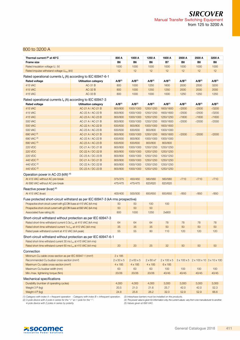
800 to 3200 A
Thermal current Ith at 40°C 800 A 1000 A 1250 A 1600 A 2000 A 2500 A 3200 A
Frame size B6 B6 B6 B7 B8 B8 B8
Rated insulation voltage Ui (V) 1000 1000 1000 1000 1000 1000 1000
Rated impulse withstand voltage Uimp (kV) 12 12 12 12 12 12 12
Rated operational currents Ie (A) according to IEC 60947-6-1Rated voltage Utilisation category A/B(1) A/B(1) A/B(1) A/B(1) A/B(1) A/B(1) A/B(1)
415 VAC AC-31 B 800 1000 1250 1600 2000 2500 3200
415 VAC AC-32 B 800 1000 1250 1250 2000 2000 2000
415 VAC AC-33 B 800 1000 1000 1000 1250 1250 1250
Rated operational currents Ie (A) according to IEC 60947-3Rated voltage Utilisation category A/B(1) A/B(1) A/B(1) A/B(1) A/B(1) A/B(1) A/B(1)
415 VAC AC-21 A / AC-21 B 800/800 1000/1000 1250/1250 1600/1600 -/2000 -/2500 -/3200
415 VAC AC-22 A / AC-22 B 800/800 1000/1000 1250/1250 1600/1600 -/2000 -/2500 -/3200
415 VAC AC-23 A / AC-23 B 800/800 1000/1000 1250/1250 1250/1250 -/1600 -/1600 -/1600
500 VAC AC-21 A / AC-21 B 800/800 1000/1000 1250/1250 1600/1600 -/2000 -/2000 -/2000
500 VAC AC-22 A / AC-22 B 630/630 800/800 1000/1000 1600/1600
500 VAC AC-23 A / AC-23 B 630/630 630/630 800/800 1000/1000
690 VAC (3) AC-21 A / AC-21 B 800/800 1000/1000 1250/1250 1600/1600 -/2000 -/2000 -/2000
690 VAC (3) AC-22 A / AC-22 B 630/630 800/800 1000/1000 1000/1000
690 VAC (3) AC-23 A / AC-23 B 630/630 630/630 800/800 800/800
220 VDC DC-21 A / DC-21 B 800/800 1000/1000 1250/1250 1250/1250
220 VDC DC-22 A / DC-22 B 800/800 1000/1000 1250/1250 1250/1250
220 VDC DC-23 A / DC-23 B 800/800 1000/1000 1250/1250 1250/1250
440 VDC (2) DC-21 A / DC-21 B 800/800 1000/1000 1250/1250 1250/1250
440 VDC (2) DC-22 A / DC-22 B 800/800 1000/1000 1250/1250 1250/1250
440 VDC (2) DC-23 A / DC-23 B 800/800 1000/1000 1250/1250 1250/1250
Operation power in AC-23 (kW) (4)
At 415 VAC without AC pre-break 375/375 450/450 560/560 560/560 -/710 -/710 -/710
At 690 VAC without AC pre-break 475/475 475/475 620/620 620/620
Reactive power (kvar) (4)
At 415 VAC (kvar) 400/400 500/500 650/650 650/650 -/850 -/850 -/850
Fuse protected short-circuit withstand as per IEC 60947-3 (kA rms prospective)Prospective short-circuit current with gG DIN fuses at 415 VAC (kA rms) 50 50 100 100
Prospective short-circuit current with gG DIN fuses at 690 VAC (kA rms) 50 50 50
Associated fuse rating (A) 800 1000 1250 2x800
Short-circuit withstand without protection as per IEC 60947-3Rated short-time withstand current 0.3s Icw at 415 VAC (kA rms) 64 64 64 78 78 78 78
Rated short-time withstand current 1s Icw at 415 VAC (kA rms) 35 35 35 50 50 50 50
Rated peak withstand current at 415 VAC (kA peak) 55 55 80 110 120 120 120
Short-circuit withstand without protection as per IEC 60947-6-1Rated short-time withstand current 30 ms Icw at 415 VAC (kA rms)
Rated short-time withstand current 60 ms Icw at 415 VAC (kA rms) 20 20 25 32 50 50 50
ConnectionMinimum Cu cable cross-section as per IEC 60947-1 (mm²) 2 x 185
Recommended Cu busbar cross-section (mm²) 2 x 50 x 5 2 x 63 x 5 2 x 60 x7 2 x 100 x 5 3 x 100 x 5 2 x 100 x 10 3 x 10 x 100
Maximum Cu cable cross-section (mm²) 4 x 185 4 x 185 4 x 185 6 x 185
Maximum Cu busbar width (mm) 63 63 63 100 100 100 100
Min./max. tightening torque (Nm) 20/26 20/26 20/26 40/45 40/45 40/45 40/45
Mechanical specificationsDurability (number of operating cycles) 4,000 4,000 4,000 3,000 3,000 3,000 3,000
Weight 3 P (kg) 20.5 21.0 21.6 25.7 42.0 42.0 52.3
Weight 4 P (kg) 24.8 25.6 26.2 32.0 52.9 52.9 66.6
(1) Category with index A = frequent operation - Category with index B = infrequent operation.(2) 3-pole device with 2 pole in series for the “+” an 1 pole for the “-”.
4-pole device with 2 poles in series by polarity.
(3) Interphase barriers must be installed on the products.(4) The power value is given for information only, the current values vary from one manufacturer to another.(5) Values given at 690 VAC.
410 General Catalogue 2018
SIRCOVERManual Transfer Switching Equipmentfrom 125 to 3200 A
Characteristics according to IEC 60947-3 and IEC 60947-6-1125 to 630 A
Thermal current Ith at 40°C 125 A 160 A 200 A 250 A 315 A 400 A 500 A 630 A
Frame size B3 B3 B3 B4 B4 B4 B5 B5
Rated insulation voltage Ui (V) 800 800 800 1000 1000 1000 1000 1000
Rated impulse withstand voltage Uimp (kV) 8 8 8 12 12 12 12 12
Rated operational currents Ie (A) according to IEC 60947-6-1Rated voltage Utilisation category A/B(1) A/B(1) A/B(1) A/B(1) A/B(1) A/B(1) A/B(1) A/B(1)
415 VAC AC-31 B 125 160 200 250 315 400 500 630
415 VAC AC-32 B 200 315 400 500 500
415 VAC AC-33 B 200 200 200 400 400
Rated operational currents Ie (A) according to IEC 60947-3Rated voltage Utilisation category A/B(1) A/B(1) A/B(1) A/B(1) A/B(1) A/B(1) A/B(1) A/B(1)
415 VAC AC-21 A / AC-21 B 125/125 160/160 200/200 250/250 315/315 400/400 500/500 630/630
415 VAC AC-22 A / AC-22 B 125/125 160/160 200/200 250/250 315/315 400/400 500/500 630/630
415 VAC AC-23 A / AC-23 B 125/125 160/160 200/200 200/200 315/315 400/400 500/500 500/630
500 VAC AC-21 A / AC-21 B 125/125 160/160 200/200 250/250 315/315 400/400 500/500 630/630
500 VAC AC-22 A / AC-22 B 125/125 160/160 200/200 200/250 200/315 200/400 500/500 500/500
500 VAC AC-23 A / AC-23 B 80/80 80/80 80/80 200/200 200/200 200/200 400/400 400/400
690 VAC (3) AC-21 A / AC-21 B 125/125 160/160 200/200 200/200 200/200 200/200 500/500 500/500
690 VAC (3) AC-22 A / AC-22 B 125/125 125/125 125/125 160/160 160/160 160/160 400/400 400/400
690 VAC (3) AC-23 A / AC-23 B 63/80 63/80 63/80 125/125 125/125 125/125 400/400 400/400
220 VDC DC-21 A / DC-21 B 125/125 160/160 200/200 250/250 250/250 250/250 500/500 630/630
220 VDC DC-22 A / DC-22 B 125/125 160/160 200/200 250/250 250/250 250/250 500/500 630/630
220 VDC DC-23 A / DC-23 B 125/125 125/125 125/125 200/200 200/200 200/200 500/500 630/630
440 VDC (2) DC-21 A / DC-21 B 125/125 125/125 125/125 200/200 200/200 200/200 500/500 630/630
440 VDC (2) DC-22 A / DC-22 B 125/125 125/125 125/125 200/200 200/200 200/200 500/500 630/630
440 VDC (2) DC-23 A / DC-23 B 125/125 125/125 125/125 200/200 200/200 200/200 500/500 630/630
Operation power in AC-23 (kW) (4)
At 415 VAC without AC pre-break 58/58 75/75 100/100 100/100 145/145 190/190 235/235 235/280
At 690 VAC without AC pre-break 50/62 50/62 50/62 90/90 90/90 90/90 310/310 310/310
Reactive power (kvar) (4)
At 415 VAC (kvar) 60/60 75/75 100/100 125/125 150/150 200/200 250/250 250/300
Fuse protected short-circuit withstand as per IEC 60947-3 (kA rms prospective)Prospective short-circuit current with gG DIN fuses at 415 VAC (kA rms) 100 100 50 50 50 50 50 50
Prospective short-circuit current with gG DIN fuses at 690 VAC (kA rms) 50 50 50 50 50
Associated fuse rating (A) 125 160 200 250 315 400 500 630
Short-circuit withstand without protection as per IEC 60947-3Rated short-time withstand current 0.3s Icw at 415 VAC (kA rms) 12 12 12 15 (5) 15 (5) 15 (5) 17 (5) 17 (5)
Rated short-time withstand current 1s Icw at 415 VAC (kA rms) 7 7 7 8 (5) 8 (5) 8 (5) 11 (5) 10 (5)
Rated peak withstand current at 415 VAC (kA peak) 20 20 20 30 30 30 45 45
Short-circuit withstand without protection as per IEC 60947-6-1Rated short-time withstand current 30 ms Icw at 415 VAC (kA rms) 10 10 10 10 10 10
Rated short-time withstand current 60 ms Icw at 415 VAC (kA rms) 10 12.6
ConnectionMinimum Cu cable cross-section as per IEC 60947-1 (mm²) 35 35 50 95 120 185 2 x 95 2 x 120
Recommended Cu busbar cross-section (mm²) 2 x 32 x 5 2 x 40 x 5
Maximum Cu cable cross-section (mm²) 50 95 120 150 240 240 2 x 185 2 x 300
Maximum Cu busbar width (mm) 25 25 25 32 32 32 50 50
Min./max. tightening torque (Nm) 9/13 9/13 9/13 20/26 20/26 20/26 20/26 20/26
Mechanical specificationsDurability (number of operating cycles) 10,000 10,000 10,000 8 ,000 8,000 8,000 5,000 5,000
Weight 3 P (kg) 2.9 2.9 2.9 3.8 3.9 3.9 8.6 9.1
Weight 4 P (kg) 4.1 4.1 4.1 4.6 4.9 4.9 10.4 11.1
(1) Category with index A = frequent operation - Category with index B = infrequent operation.(2) 3-pole device with 2 pole in series for the “+” an 1 pole for the “-”.
4-pole device with 2 poles in series by polarity.
(3) Interphase barriers must be installed on the products.(4) The power value is given for information only, the current values vary from one manufacturer to another.(5) Values given at 690 VAC.
SIRCOVERManual Transfer Switching Equipment
from 125 to 3200 A
800 to 3200 A
Thermal current Ith at 40°C 800 A 1000 A 1250 A 1600 A 2000 A 2500 A 3200 A
Frame size B6 B6 B6 B7 B8 B8 B8
Rated insulation voltage Ui (V) 1000 1000 1000 1000 1000 1000 1000
Rated impulse withstand voltage Uimp (kV) 12 12 12 12 12 12 12
Rated operational currents Ie (A) according to IEC 60947-6-1Rated voltage Utilisation category A/B(1) A/B(1) A/B(1) A/B(1) A/B(1) A/B(1) A/B(1)
415 VAC AC-31 B 800 1000 1250 1600 2000 2500 3200
415 VAC AC-32 B 800 1000 1250 1250 2000 2000 2000
415 VAC AC-33 B 800 1000 1000 1000 1250 1250 1250
Rated operational currents Ie (A) according to IEC 60947-3Rated voltage Utilisation category A/B(1) A/B(1) A/B(1) A/B(1) A/B(1) A/B(1) A/B(1)
415 VAC AC-21 A / AC-21 B 800/800 1000/1000 1250/1250 1600/1600 -/2000 -/2500 -/3200
415 VAC AC-22 A / AC-22 B 800/800 1000/1000 1250/1250 1600/1600 -/2000 -/2500 -/3200
415 VAC AC-23 A / AC-23 B 800/800 1000/1000 1250/1250 1250/1250 -/1600 -/1600 -/1600
500 VAC AC-21 A / AC-21 B 800/800 1000/1000 1250/1250 1600/1600 -/2000 -/2000 -/2000
500 VAC AC-22 A / AC-22 B 630/630 800/800 1000/1000 1600/1600
500 VAC AC-23 A / AC-23 B 630/630 630/630 800/800 1000/1000
690 VAC (3) AC-21 A / AC-21 B 800/800 1000/1000 1250/1250 1600/1600 -/2000 -/2000 -/2000
690 VAC (3) AC-22 A / AC-22 B 630/630 800/800 1000/1000 1000/1000
690 VAC (3) AC-23 A / AC-23 B 630/630 630/630 800/800 800/800
220 VDC DC-21 A / DC-21 B 800/800 1000/1000 1250/1250 1250/1250
220 VDC DC-22 A / DC-22 B 800/800 1000/1000 1250/1250 1250/1250
220 VDC DC-23 A / DC-23 B 800/800 1000/1000 1250/1250 1250/1250
440 VDC (2) DC-21 A / DC-21 B 800/800 1000/1000 1250/1250 1250/1250
440 VDC (2) DC-22 A / DC-22 B 800/800 1000/1000 1250/1250 1250/1250
440 VDC (2) DC-23 A / DC-23 B 800/800 1000/1000 1250/1250 1250/1250
Operation power in AC-23 (kW) (4)
At 415 VAC without AC pre-break 375/375 450/450 560/560 560/560 -/710 -/710 -/710
At 690 VAC without AC pre-break 475/475 475/475 620/620 620/620
Reactive power (kvar) (4)
At 415 VAC (kvar) 400/400 500/500 650/650 650/650 -/850 -/850 -/850
Fuse protected short-circuit withstand as per IEC 60947-3 (kA rms prospective)Prospective short-circuit current with gG DIN fuses at 415 VAC (kA rms) 50 50 100 100
Prospective short-circuit current with gG DIN fuses at 690 VAC (kA rms) 50 50 50
Associated fuse rating (A) 800 1000 1250 2x800
Short-circuit withstand without protection as per IEC 60947-3Rated short-time withstand current 0.3s Icw at 415 VAC (kA rms) 64 64 64 78 78 78 78
Rated short-time withstand current 1s Icw at 415 VAC (kA rms) 35 35 35 50 50 50 50
Rated peak withstand current at 415 VAC (kA peak) 55 55 80 110 120 120 120
Short-circuit withstand without protection as per IEC 60947-6-1Rated short-time withstand current 30 ms Icw at 415 VAC (kA rms)
Rated short-time withstand current 60 ms Icw at 415 VAC (kA rms) 20 20 25 32 50 50 50
ConnectionMinimum Cu cable cross-section as per IEC 60947-1 (mm²) 2 x 185
Recommended Cu busbar cross-section (mm²) 2 x 50 x 5 2 x 63 x 5 2 x 60 x7 2 x 100 x 5 3 x 100 x 5 2 x 100 x 10 3 x 10 x 100
Maximum Cu cable cross-section (mm²) 4 x 185 4 x 185 4 x 185 6 x 185
Maximum Cu busbar width (mm) 63 63 63 100 100 100 100
Min./max. tightening torque (Nm) 20/26 20/26 20/26 40/45 40/45 40/45 40/45
Mechanical specificationsDurability (number of operating cycles) 4,000 4,000 4,000 3,000 3,000 3,000 3,000
Weight 3 P (kg) 20.5 21.0 21.6 25.7 42.0 42.0 52.3
Weight 4 P (kg) 24.8 25.6 26.2 32.0 52.9 52.9 66.6
(1) Category with index A = frequent operation - Category with index B = infrequent operation.(2) 3-pole device with 2 pole in series for the “+” an 1 pole for the “-”.
4-pole device with 2 poles in series by polarity.
(3) Interphase barriers must be installed on the products.(4) The power value is given for information only, the current values vary from one manufacturer to another.(5) Values given at 690 VAC.
411General Catalogue 2018
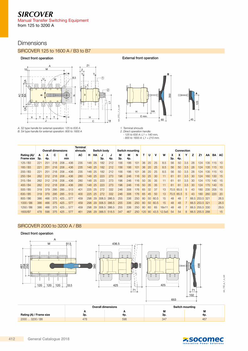
SIRCOVERManual Transfer Switching Equipmentfrom 125 to 3200 A
Direct front operation
Rating (A) / Frame size
Overall dimensions Switch mounting
A 3p.
A 4p.
M 3p.
M 4p.
2000 … 3200 / B8 478 598 347 467
425
653
436.5
425
380
M 51.5
53.5120120120
A
258
250
461
498
71
102
498
71
svr_
150_
a_1_
x_ca
t
SIRCOVER 2000 to 3200 A / B8
Dimensions
Direct front operation External front operation
Rating (A)/Frame size
Overall dimensionsTerminal shrouds Switch body Switch mounting Connection
A 3p.
A 4p.
C E min
AC H HA J 3p.
J 4p.
M 3p.
M 4p.
N T U V W X 3p.
X 4p.
Y Z Z1 AA BA AC
125 / B3 221 251 218 208 … 436 235 148 25 182 212 156 186 101 36 20 25 8.5 56 50 3.5 28 124 135 115 10
160 / B3 221 251 218 208 … 436 235 148 25 182 212 156 186 101 36 20 25 8.5 56 50 3.5 28 124 135 115 10
200 / B3 221 251 218 208 … 436 235 148 25 182 212 156 186 101 36 20 25 8.5 56 50 3.5 28 124 135 115 10
250 / B4 262 312 218 208 … 436 280 148 25 223 273 196 246 116 50 25 30 11 61 61 3.5 30 124 160 130 15
315 / B4 262 312 218 208 … 436 280 148 25 223 273 196 246 116 50 35 35 11 61 61 3.5 30 124 170 140 15
400 / B4 262 312 218 208 … 436 280 148 25 223 273 196 246 116 50 35 35 11 61 61 3.5 30 124 170 140 15
500 / B5 319 379 295 285 … 513 401 225 25 272 332 246 306 176 65 32 37 13 70.5 65.5 5 43 180 235 205 15
630 / B5 319 379 295 285 … 513 400 225 25 272 332 246 306 176 65 45 50 13 70.5 65.5 5 43 180 260 220 20
800 / B6 386 466 375 425 … 577 459 298 29 306.5 386.5 255 336 250 80 50 60.5 15 48 48 7 66.5 253.5 321 26.5
1000 / B6 386 466 375 425 … 577 459 298 29 306.5 386.5 255 336 250 80 50 60.5 15 48 48 7 66.5 253.5 321 26.5
1250 / B6 386 466 375 425 … 577 459 298 29 306.5 386.5 255 336 250 80 60 65 16x11 48 48 7 66.5 255.5 330 29.5
1600/B7 478 598 375 425 … 577 461 298 29 388.5 518.5 347 467 250 120 90 43.5 12.5x5 54 54 8 66.5 255.5 288 15
II I
350
125
L1
N
V
60 45
B
0
III
A
8.5
C
H18
10A Z1
Z
Y Y
1
2
H HA
E min.X T TJ
T
M
U W
AC
AA
BA
CA
CA
svr_
072_
i_1_
x_ca
t
A. S2 type handle for external operation: 125 to 630 AB. S4 type handle for external operation: 800 to 1600 A
1. Terminal shrouds2. Direct operation handle:
- 125 to 630 A: L1 = 140 mm, - 800 to 1600 A: L1 = 210 mm.
SIRCOVER 125 to 1600 A / B3 to B7
SIRCOVERManual Transfer Switching Equipment
from 125 to 3200 A
33 8.58.5
50
3310
ø 9
ø 15
svr_
077_
a_1_
x_ca
t
SIRCOVER and SIRCOVER Bypass 800 A / B6
Connection terminals
15
5 5
12.5
25 253030
454590
ø12.5
svr_
098_
a_1_
x_ca
t
SIRCOVER 1600 to 3200 A / B7 to B8 SIRCOVER Bypass 1600 A / B7
SIRCOVER and SIRCOVER Bypass 1250 A / B6
16 x 11
60
28.5 15.7515.75
28.5
15.2
5
svr_
078_
b_1_
x_ca
t
Direct front operation
External front operation
Rating (A) /Frame size
Overall dimensionsTerminal shrouds Switch body Switch mounting Connection
A 3+6p.
A 4+8p. C
E min AC H HA
J 3+6 p.
J 4+8 p.
M 3+6 p.
M 4+8 p. N T U V W
X 3+6p.
X 4+8p. Y Z Z1 Z2 AA BA AC
125 / B3 221 251 313 320 235 243 25 182 212 156 186 101 36 20 25 8.5 56 50 3.5 28 124 219 135 115 10
160 / B3 221 251 313 320 235 243 25 182 212 156 186 101 36 20 25 8.5 56 50 3.5 28 124 219 135 115 10
200 / B3 221 251 313 320 235 243 25 182 212 156 186 101 36 20 25 8.5 56 50 3.5 28 124 219 135 115 10
250 / B4 262 312 313 298 280 243 25 223 273 196 246 116 50 25 30 11 61 61 3.5 30 124 219 160 130 10
400 / B4 262 312 313 298 280 243 25 223 273 196 246 116 50 35 35 11 61 61 3.5 30 124 219 170 140 15
500 / B5 319 379 432 417 401 362 25 272 332 246 306 176 65 32 37 13 70.5 65.5 5 43 180 317 235 205 15
630 / B5 319 379 432 417 400 362 25 272 332 246 306 176 65 45 50 13 70.5 65.5 5 43 180 317 260 220 20
800 / B6 386 466 560 550 459 479 29 306.5 386.5 255 335 250 80 50 60.5 15 48 48 7 66.5 253.5 439.5 321 26.5
1250 / B6 386 466 560 550 459 479 29 306.5 386.5 255 335 250 80 60 65 16x11 48 48 7 66.5 253.5 439.5 320 29.25
1600/B7 478 598 560 550 461 479 29 388.5 518.5 347 467 250 120 90 43.5 12.5x5 54 54 8 66.5 253.5 439.5 288 15
210
125
330
==
BA C
61
45HA
E min.
H
J
X T
U W
A10
8.5
ZZ1
Z2
Y Y Y
1
2
18CH
L1
CA
CA
BA
AA
AC
V
II
I III
I
0 N
M
T T
103
svr_
070_
i_1_
x_ca
t
A. S2 type handle for external operation: 125 to 200 AB. S3 type handle for external operation: 250 to 630 AC. External double lever handle: 800 to 1600 A
1. Terminal shrouds2. Direct operation handle:
- 125 to 200 A: L1 = 140 mm, - 250 to 630 A: L1 = 210 mm, - 800 to 1600 A: L1 = diameter 330 mm.
SIRCOVER Bypass 125 to 1600 A / B3 to B7
412 General Catalogue 2018
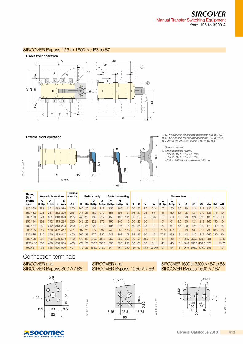
SIRCOVERManual Transfer Switching Equipmentfrom 125 to 3200 A
Direct front operation
Rating (A) / Frame size
Overall dimensions Switch mounting
A 3p.
A 4p.
M 3p.
M 4p.
2000 … 3200 / B8 478 598 347 467
425
653
436.5
425
380
M 51.5
53.5120120120
A
258
250
461
498
71
102
498
71
svr_
150_
a_1_
x_ca
t
SIRCOVER 2000 to 3200 A / B8
Dimensions
Direct front operation External front operation
Rating (A)/Frame size
Overall dimensionsTerminal shrouds Switch body Switch mounting Connection
A 3p.
A 4p.
C E min
AC H HA J 3p.
J 4p.
M 3p.
M 4p.
N T U V W X 3p.
X 4p.
Y Z Z1 AA BA AC
125 / B3 221 251 218 208 … 436 235 148 25 182 212 156 186 101 36 20 25 8.5 56 50 3.5 28 124 135 115 10
160 / B3 221 251 218 208 … 436 235 148 25 182 212 156 186 101 36 20 25 8.5 56 50 3.5 28 124 135 115 10
200 / B3 221 251 218 208 … 436 235 148 25 182 212 156 186 101 36 20 25 8.5 56 50 3.5 28 124 135 115 10
250 / B4 262 312 218 208 … 436 280 148 25 223 273 196 246 116 50 25 30 11 61 61 3.5 30 124 160 130 15
315 / B4 262 312 218 208 … 436 280 148 25 223 273 196 246 116 50 35 35 11 61 61 3.5 30 124 170 140 15
400 / B4 262 312 218 208 … 436 280 148 25 223 273 196 246 116 50 35 35 11 61 61 3.5 30 124 170 140 15
500 / B5 319 379 295 285 … 513 401 225 25 272 332 246 306 176 65 32 37 13 70.5 65.5 5 43 180 235 205 15
630 / B5 319 379 295 285 … 513 400 225 25 272 332 246 306 176 65 45 50 13 70.5 65.5 5 43 180 260 220 20
800 / B6 386 466 375 425 … 577 459 298 29 306.5 386.5 255 336 250 80 50 60.5 15 48 48 7 66.5 253.5 321 26.5
1000 / B6 386 466 375 425 … 577 459 298 29 306.5 386.5 255 336 250 80 50 60.5 15 48 48 7 66.5 253.5 321 26.5
1250 / B6 386 466 375 425 … 577 459 298 29 306.5 386.5 255 336 250 80 60 65 16x11 48 48 7 66.5 255.5 330 29.5
1600/B7 478 598 375 425 … 577 461 298 29 388.5 518.5 347 467 250 120 90 43.5 12.5x5 54 54 8 66.5 255.5 288 15
II I
350
125
L1
N
V
60 45
B
0
III
A
8.5
C
H18
10A Z1
Z
Y Y
1
2
H HA
E min.X T TJ
T
M
U W
AC
AA
BA
CA
CA
svr_
072_
i_1_
x_ca
t
A. S2 type handle for external operation: 125 to 630 AB. S4 type handle for external operation: 800 to 1600 A
1. Terminal shrouds2. Direct operation handle:
- 125 to 630 A: L1 = 140 mm, - 800 to 1600 A: L1 = 210 mm.
SIRCOVER 125 to 1600 A / B3 to B7
SIRCOVERManual Transfer Switching Equipment
from 125 to 3200 A
33 8.58.5
50
3310
ø 9
ø 15
svr_
077_
a_1_
x_ca
t
SIRCOVER and SIRCOVER Bypass 800 A / B6
Connection terminals
15
5 5
12.5
25 253030
454590
ø12.5
svr_
098_
a_1_
x_ca
t
SIRCOVER 1600 to 3200 A / B7 to B8 SIRCOVER Bypass 1600 A / B7
SIRCOVER and SIRCOVER Bypass 1250 A / B6
16 x 11
60
28.5 15.7515.75
28.5
15.2
5
svr_
078_
b_1_
x_ca
t
Direct front operation
External front operation
Rating (A) /Frame size
Overall dimensionsTerminal shrouds Switch body Switch mounting Connection
A 3+6p.
A 4+8p. C
E min AC H HA
J 3+6 p.
J 4+8 p.
M 3+6 p.
M 4+8 p. N T U V W
X 3+6p.
X 4+8p. Y Z Z1 Z2 AA BA AC
125 / B3 221 251 313 320 235 243 25 182 212 156 186 101 36 20 25 8.5 56 50 3.5 28 124 219 135 115 10
160 / B3 221 251 313 320 235 243 25 182 212 156 186 101 36 20 25 8.5 56 50 3.5 28 124 219 135 115 10
200 / B3 221 251 313 320 235 243 25 182 212 156 186 101 36 20 25 8.5 56 50 3.5 28 124 219 135 115 10
250 / B4 262 312 313 298 280 243 25 223 273 196 246 116 50 25 30 11 61 61 3.5 30 124 219 160 130 10
400 / B4 262 312 313 298 280 243 25 223 273 196 246 116 50 35 35 11 61 61 3.5 30 124 219 170 140 15
500 / B5 319 379 432 417 401 362 25 272 332 246 306 176 65 32 37 13 70.5 65.5 5 43 180 317 235 205 15
630 / B5 319 379 432 417 400 362 25 272 332 246 306 176 65 45 50 13 70.5 65.5 5 43 180 317 260 220 20
800 / B6 386 466 560 550 459 479 29 306.5 386.5 255 335 250 80 50 60.5 15 48 48 7 66.5 253.5 439.5 321 26.5
1250 / B6 386 466 560 550 459 479 29 306.5 386.5 255 335 250 80 60 65 16x11 48 48 7 66.5 253.5 439.5 320 29.25
1600/B7 478 598 560 550 461 479 29 388.5 518.5 347 467 250 120 90 43.5 12.5x5 54 54 8 66.5 253.5 439.5 288 15
210
125
330
==
BA C
61
45HA
E min.
H
J
X T
U W
A10
8.5
ZZ1
Z2
Y Y Y
1
2
18CH
L1
CA
CA
BA
AA
AC
V
II
I III
I
0 N
M
T T
103
svr_
070_
i_1_
x_ca
t
A. S2 type handle for external operation: 125 to 200 AB. S3 type handle for external operation: 250 to 630 AC. External double lever handle: 800 to 1600 A
1. Terminal shrouds2. Direct operation handle:
- 125 to 200 A: L1 = 140 mm, - 250 to 630 A: L1 = 210 mm, - 800 to 1600 A: L1 = diameter 330 mm.
SIRCOVER Bypass 125 to 1600 A / B3 to B7
413General Catalogue 2018

SIRCOVERManual Transfer Switching Equipmentfrom 125 to 3200 A
Dimensions for external handles
4 Ø 7
2 Ø 6.5
20 20
Ø 37
Ø 37
79
22
45°
1414
S2 type
Direction of operationHandle type Door drilling
With lockRONIS EL11AP
With lockCASTELL K
Ø78
45
125
4 Ø 7
1414
20 20
(1)Ø D
90° 90°
I II
0or
I+II
4 Ø 5.5
Ø 26
4 Ø 7
20 20
Ø 37
73.5
2624
45° 3.5
28
1414
28.5
Front operation
poig
n_03
0_a_
1_gb
_cat
(1) Ø31 to Ø37: rear screw mounting, Ø37: front clip mounting.
SIRCOVER 125 to 630 A / B3 to B5
0or
I+II
I II
60
350
Ø78
(2)4 Ø 7
1414
20 20
(1)Ø D
90° 90°
4 Ø 7
2 Ø 6.5
20 20
Ø 37
Ø 37
79
22
45°
1414
4 Ø 5.5
Ø 26
4 Ø 7
20 20
Ø 37
73.5
2624
45° 3.5
28
1414
28.5
S4 type
Direction of operationHandle type Door drilling
With lockRONIS EL11AP
With lockCASTELL K
Front operation
poig
n_03
1_a_
1_gb
_cat
(1) Ø31 to Ø37: rear screw mounting, Ø37 : front clip mounting.
(2) Ø6 to Ø7: clip mounting
SIRCOVER 800 to 1600 A / B6 to B7
S5 typewith V Escutcheon
90°
498
I
II
0
90°
71
102
50
Ø 31
50
4 Ø 6,5
With lockCASTELL K
9650
50
25
28
4 x Ø 6.5 3 x Ø 6.5Ø 31
Direction of operationHandle type
Front operation
Door drilling
poig
n_02
3_a_
1_gb
_cat
SIRCOVER 2000 to 3200 A / B8
SIRCOVERManual Transfer Switching Equipment
from 125 to 3200 A
Ø78
45
125
4 Ø 7
1414
20 20
(1)Ø D
90° 90°
I II
0
4 Ø 7
2 Ø 6.5
20 20
Ø 37
Ø 37
79
22
45°
1414
4 Ø 5.5
Ø 26
4 Ø 7
20 20
Ø 37
73.5
2624
45° 3.5
28
1414
28.5
S2 type
Direction of operationHandle type
Front operation
Door drilling
With lockRONIS EL11AP
With lockCASTELL K
poig
n_03
2_a_
1_gb
_cat
(1) Ø31 to Ø37: rear screw mounting, Ø37: front clip mounting.
SIRCOVER Bypass 125 to 200 A / B3
4 Ø 7
1414
20 20
(1)Ø D
Ø78
61
210
90° 90°
I II
0
4 Ø 7
2 Ø 6.5
20 20
Ø 37
Ø 37
79
22
45°
1414
4 Ø 5.5
Ø 26
4 Ø 7
20 20
Ø 37
73.5
2624
45° 3.5
28
1414
28.5
S3 type
Direction of operationHandle type
Front operation
Door drilling
With lockRONIS EL11AP
With lockCASTELL K
poig
n_03
3_a_
1_gb
_cat
(1) Ø31 to Ø37: rear screw mounting, Ø37: front clip mounting.
SIRCOVER Bypass 250 to 630 A / B4 to B5
C type
0
II
I
90°
90°
50
Ø 3130
0
50
4 Ø 6.5
9650
50
25
28
4 x Ø 6.5 3 x Ø 6.5Ø 31
Direction of operationHandle type
Front operation
Door drilling
With lockCASTELL K
poig
n_02
2_a_
1_gb
_cat
SIRCOVER Bypass 800 to 1600 A / B6 to B7
414 General Catalogue 2018

SIRCOVERManual Transfer Switching Equipmentfrom 125 to 3200 A
Dimensions for external handles
4 Ø 7
2 Ø 6.5
20 20
Ø 37
Ø 37
79
22
45°
1414
S2 type
Direction of operationHandle type Door drilling
With lockRONIS EL11AP
With lockCASTELL K
Ø78
45
125
4 Ø 7
1414
20 20
(1)Ø D
90° 90°
I II
0or
I+II
4 Ø 5.5
Ø 26
4 Ø 7
20 20
Ø 37
73.5
2624
45° 3.5
28
1414
28.5
Front operation
poig
n_03
0_a_
1_gb
_cat
(1) Ø31 to Ø37: rear screw mounting, Ø37: front clip mounting.
SIRCOVER 125 to 630 A / B3 to B5
0or
I+II
I II
60
350
Ø78
(2)4 Ø 7
1414
20 20
(1)Ø D
90° 90°
4 Ø 7
2 Ø 6.5
20 20
Ø 37
Ø 37
79
22
45°
1414
4 Ø 5.5
Ø 26
4 Ø 7
20 20
Ø 37
73.5
2624
45° 3.5
28
1414
28.5
S4 type
Direction of operationHandle type Door drilling
With lockRONIS EL11AP
With lockCASTELL K
Front operation
poig
n_03
1_a_
1_gb
_cat
(1) Ø31 to Ø37: rear screw mounting, Ø37 : front clip mounting.
(2) Ø6 to Ø7: clip mounting
SIRCOVER 800 to 1600 A / B6 to B7
S5 typewith V Escutcheon
90°
498
I
II
0
90°
71
102
50
Ø 31
50
4 Ø 6,5
With lockCASTELL K
9650
50
25
28
4 x Ø 6.5 3 x Ø 6.5Ø 31
Direction of operationHandle type
Front operation
Door drilling
poig
n_02
3_a_
1_gb
_cat
SIRCOVER 2000 to 3200 A / B8
SIRCOVERManual Transfer Switching Equipment
from 125 to 3200 A
Ø78
45
125
4 Ø 7
1414
20 20
(1)Ø D
90° 90°
I II
0
4 Ø 7
2 Ø 6.5
20 20
Ø 37
Ø 37
79
22
45°
1414
4 Ø 5.5
Ø 26
4 Ø 7
20 20
Ø 37
73.5
2624
45° 3.5
28
1414
28.5
S2 type
Direction of operationHandle type
Front operation
Door drilling
With lockRONIS EL11AP
With lockCASTELL K
poig
n_03
2_a_
1_gb
_cat
(1) Ø31 to Ø37: rear screw mounting, Ø37: front clip mounting.
SIRCOVER Bypass 125 to 200 A / B3
4 Ø 7
1414
20 20
(1)Ø D
Ø78
61
210
90° 90°
I II
0
4 Ø 7
2 Ø 6.5
20 20
Ø 37
Ø 37
79
22
45°
1414
4 Ø 5.5
Ø 26
4 Ø 7
20 20
Ø 37
73.5
2624
45° 3.5
28
1414
28.5
S3 type
Direction of operationHandle type
Front operation
Door drilling
With lockRONIS EL11AP
With lockCASTELL K
poig
n_03
3_a_
1_gb
_cat
(1) Ø31 to Ø37: rear screw mounting, Ø37: front clip mounting.
SIRCOVER Bypass 250 to 630 A / B4 to B5
C type
0
II
I
90°
90°
50
Ø 31
300
50
4 Ø 6.5
9650
50
25
28
4 x Ø 6.5 3 x Ø 6.5Ø 31
Direction of operationHandle type
Front operation
Door drilling
With lockCASTELL K
poig
n_02
2_a_
1_gb
_cat
SIRCOVER Bypass 800 to 1600 A / B6 to B7
415General Catalogue 2018
Related Documents