Reference Manual 00809-0200-4648, Rev BB July 2016 Rosemount ™ 648 Wireless Temperature Transmitter with Rosemount X-well ™ Technology

Welcome message from author
This document is posted to help you gain knowledge. Please leave a comment to let me know what you think about it! Share it to your friends and learn new things together.
Transcript
Reference Manual00809-0200-4648, Rev BB
July 2016
Rosemount™ 648 Wireless Temperature Transmitterwith Rosemount X-well™ Technology


Reference Manual 00809-0200-4648, Rev BB
Title PageJuly 2016
Rosemount™ 648 Wireless Temperature Transmitter
iiiTitle Page
Rosemount 648 Wireless Hardware RevisionHART® Device RevisionDevice Install Kit/DD Revision
14Device Revision 4, DD Revision 1 or higher
NOTICE
Read this manual before working with the product. For personal and system safety, and for optimum product performance, make sure to thoroughly understand the contents before installing, using, or maintaining this product.
For technical assistance. contacts are listed below:
Customer Central
Technical support, quoting, and order related questions.
United States:1-800-999-9307 (7:00 a.m. to 7:00 p.m. CST)
Asia Pacific:
65 777 8211Europe/ Middle East/ Africa:
49 (8153) 9390
North American Response Center
Equipment service needs
1-800-654-7768 (24 hours - includes Canada)
Outside of these areas, contact your local Emerson™ Process Management representative.
The products described in this document are NOT designed for nuclear-qualified applications.
Using non-nuclear qualified products in applications that require nuclear-qualified hardware or products may cause inaccurate readings.
For information on Rosemount nuclear-qualified products, contact a Emerson Process Management Sales Representative.

Reference Manual00809-0200-4648, Rev BB
Title PageJuly 2016
Failure to follow these installation guidelines could result in death or serious injury.
Make sure only qualified personnel perform the installation.Explosions could result in death or serious injury.
Installation of this transmitter in an explosive environment must be in accordance with the appropriate local, national, and international standards, codes, and practices. Review the approvals section of the Rosemount 648 Wireless Reference Manual for any restrictions associated with a safe installation.
Before connecting a Field Communicator in an explosive atmosphere, ensure the instruments are installed in accordance with intrinsically safe or non-incendive field wiring practices.
Process leaks may cause harm or result in death.
Install and tighten process connectors before applying pressure.Electrical shock can result in death or serious injury.
Avoid contact with the leads and terminals. High voltage that may be present on leads can cause electrical shock.
This device complies with Part 15 of the FCC Rules. Operation is subject to the following conditions:
This device may not cause harmful interference. This device must accept any interference received, including interference that may
cause undesired operation. This device must be installed to ensure a minimum antenna separation distance of
20 cm from all persons. The power module may be replaced in a hazardous area. The power module has
surface resistivity greater than one gigaohm and must be properly installed in the wireless device enclosure. Care must be taken during transportation to and from the point of installation to prevent electrostatic charge build-up.
iv Title Page
Reference Manual 00809-0200-4648, Rev BB
Title PageJuly 2016
NOTICE
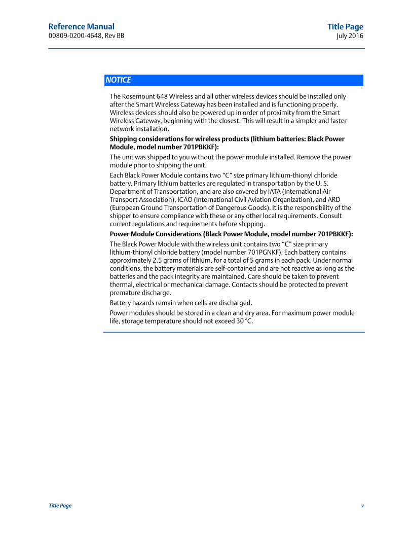
The Rosemount 648 Wireless and all other wireless devices should be installed only after the Smart Wireless Gateway has been installed and is functioning properly. Wireless devices should also be powered up in order of proximity from the Smart Wireless Gateway, beginning with the closest. This will result in a simpler and faster network installation.
Shipping considerations for wireless products (lithium batteries: Black Power Module, model number 701PBKKF):
The unit was shipped to you without the power module installed. Remove the power module prior to shipping the unit.
Each Black Power Module contains two “C” size primary lithium-thionyl chloride battery. Primary lithium batteries are regulated in transportation by the U. S. Department of Transportation, and are also covered by IATA (International Air Transport Association), ICAO (International Civil Aviation Organization), and ARD (European Ground Transportation of Dangerous Goods). It is the responsibility of the shipper to ensure compliance with these or any other local requirements. Consult current regulations and requirements before shipping.
Power Module Considerations (Black Power Module, model number 701PBKKF):
The Black Power Module with the wireless unit contains two “C” size primary lithium-thionyl chloride battery (model number 701PGNKF). Each battery contains approximately 2.5 grams of lithium, for a total of 5 grams in each pack. Under normal conditions, the battery materials are self-contained and are not reactive as long as the batteries and the pack integrity are maintained. Care should be taken to prevent thermal, electrical or mechanical damage. Contacts should be protected to prevent premature discharge.
Battery hazards remain when cells are discharged.
Power modules should be stored in a clean and dry area. For maximum power module life, storage temperature should not exceed 30 °C.
vTitle Page

vi
Reference Manual00809-0200-4648, Rev BB
Title PageJuly 2016
Title Page

Reference Manual 00809-0200-4648, Rev BB
ContentsJuly 2016
Contents
1Section 1: Introduction1.1 Using this manual . . . . . . . . . . . . . . . . . . . . . . . . . . . . . . . . . . . . . . . . . . . . . . . . . . . . . . . . . . . . . . . . . 1
1.2 Product recycling/disposal. . . . . . . . . . . . . . . . . . . . . . . . . . . . . . . . . . . . . . . . . . . . . . . . . . . . . . . . . . 1
2Section 2: Configuration2.1 Overview . . . . . . . . . . . . . . . . . . . . . . . . . . . . . . . . . . . . . . . . . . . . . . . . . . . . . . . . . . . . . . . . . . . . . . . . . 3
2.2 Safety messages. . . . . . . . . . . . . . . . . . . . . . . . . . . . . . . . . . . . . . . . . . . . . . . . . . . . . . . . . . . . . . . . . . . 3
2.3 Sensor connections . . . . . . . . . . . . . . . . . . . . . . . . . . . . . . . . . . . . . . . . . . . . . . . . . . . . . . . . . . . . . . . . 4
2.3.1 Thermocouple or millivolts inputs . . . . . . . . . . . . . . . . . . . . . . . . . . . . . . . . . . . . . . . . . . . . . 4
2.3.2 RTD or ohm inputs . . . . . . . . . . . . . . . . . . . . . . . . . . . . . . . . . . . . . . . . . . . . . . . . . . . . . . . . . . . 4
2.4 Bench top configuration. . . . . . . . . . . . . . . . . . . . . . . . . . . . . . . . . . . . . . . . . . . . . . . . . . . . . . . . . . . . 8
2.4.1 Field Communicator . . . . . . . . . . . . . . . . . . . . . . . . . . . . . . . . . . . . . . . . . . . . . . . . . . . . . . . . . 9
2.4.2 AMS Device Manager and AMS Wireless Configurator . . . . . . . . . . . . . . . . . . . . . . . . . . . . 9
2.4.3 Smart Wireless Gateway . . . . . . . . . . . . . . . . . . . . . . . . . . . . . . . . . . . . . . . . . . . . . . . . . . . . . 10
2.4.4 Default settings . . . . . . . . . . . . . . . . . . . . . . . . . . . . . . . . . . . . . . . . . . . . . . . . . . . . . . . . . . . . 10
2.4.5 Device sensor configuration. . . . . . . . . . . . . . . . . . . . . . . . . . . . . . . . . . . . . . . . . . . . . . . . . . 10
2.5 HART menu tree. . . . . . . . . . . . . . . . . . . . . . . . . . . . . . . . . . . . . . . . . . . . . . . . . . . . . . . . . . . . . . . . . . 11
2.6 Basic setup . . . . . . . . . . . . . . . . . . . . . . . . . . . . . . . . . . . . . . . . . . . . . . . . . . . . . . . . . . . . . . . . . . . . . . 14
2.6.1 Configure sensor type . . . . . . . . . . . . . . . . . . . . . . . . . . . . . . . . . . . . . . . . . . . . . . . . . . . . . . . 14
2.6.2 Join device to network . . . . . . . . . . . . . . . . . . . . . . . . . . . . . . . . . . . . . . . . . . . . . . . . . . . . . . . 14
2.6.3 Configure update rate . . . . . . . . . . . . . . . . . . . . . . . . . . . . . . . . . . . . . . . . . . . . . . . . . . . . . . . 15
2.7 Fast Key sequence . . . . . . . . . . . . . . . . . . . . . . . . . . . . . . . . . . . . . . . . . . . . . . . . . . . . . . . . . . . . . . . . 17
2.8 Calibration. . . . . . . . . . . . . . . . . . . . . . . . . . . . . . . . . . . . . . . . . . . . . . . . . . . . . . . . . . . . . . . . . . . . . . . 17
2.8.1 Sensor input trim . . . . . . . . . . . . . . . . . . . . . . . . . . . . . . . . . . . . . . . . . . . . . . . . . . . . . . . . . . . 18
2.8.2 Transmitter-sensor matching . . . . . . . . . . . . . . . . . . . . . . . . . . . . . . . . . . . . . . . . . . . . . . . . 19
2.9 Advanced setup . . . . . . . . . . . . . . . . . . . . . . . . . . . . . . . . . . . . . . . . . . . . . . . . . . . . . . . . . . . . . . . . . . 20
2.9.1 LCD display . . . . . . . . . . . . . . . . . . . . . . . . . . . . . . . . . . . . . . . . . . . . . . . . . . . . . . . . . . . . . . . . 20
2.9.2 Rosemount X-well technology. . . . . . . . . . . . . . . . . . . . . . . . . . . . . . . . . . . . . . . . . . . . . . . . 22
2.9.3 Process Alerts . . . . . . . . . . . . . . . . . . . . . . . . . . . . . . . . . . . . . . . . . . . . . . . . . . . . . . . . . . . . . . 24
2.10 Remove power module . . . . . . . . . . . . . . . . . . . . . . . . . . . . . . . . . . . . . . . . . . . . . . . . . . . . . . . . . . . 25
3Section 3: Installation3.1 Overview . . . . . . . . . . . . . . . . . . . . . . . . . . . . . . . . . . . . . . . . . . . . . . . . . . . . . . . . . . . . . . . . . . . . . . . . 27
3.2 Safety messages. . . . . . . . . . . . . . . . . . . . . . . . . . . . . . . . . . . . . . . . . . . . . . . . . . . . . . . . . . . . . . . . . . 27
3.3 Wireless considerations . . . . . . . . . . . . . . . . . . . . . . . . . . . . . . . . . . . . . . . . . . . . . . . . . . . . . . . . . . . 28
1Contents
Reference Manual00809-0200-4648, Rev BB
ContentsJuly 2016
3.3.1 Power up sequence . . . . . . . . . . . . . . . . . . . . . . . . . . . . . . . . . . . . . . . . . . . . . . . . . . . . . . . . . 28
3.3.2 Antenna position . . . . . . . . . . . . . . . . . . . . . . . . . . . . . . . . . . . . . . . . . . . . . . . . . . . . . . . . . . . 28
3.3.3 Conduit entry . . . . . . . . . . . . . . . . . . . . . . . . . . . . . . . . . . . . . . . . . . . . . . . . . . . . . . . . . . . . . . 29
3.4 Field Communicator connections. . . . . . . . . . . . . . . . . . . . . . . . . . . . . . . . . . . . . . . . . . . . . . . . . . . 29
3.5 Physical Installation . . . . . . . . . . . . . . . . . . . . . . . . . . . . . . . . . . . . . . . . . . . . . . . . . . . . . . . . . . . . . . . 30
3.5.1 Direct mount . . . . . . . . . . . . . . . . . . . . . . . . . . . . . . . . . . . . . . . . . . . . . . . . . . . . . . . . . . . . . . . 31
3.5.2 Remote mount . . . . . . . . . . . . . . . . . . . . . . . . . . . . . . . . . . . . . . . . . . . . . . . . . . . . . . . . . . . . . 32
3.6 Rosemount X-well™ Installation . . . . . . . . . . . . . . . . . . . . . . . . . . . . . . . . . . . . . . . . . . . . . . . . . . . . 34
3.7 LCD display . . . . . . . . . . . . . . . . . . . . . . . . . . . . . . . . . . . . . . . . . . . . . . . . . . . . . . . . . . . . . . . . . . . . . . 34
3.8 Ground the transmitter . . . . . . . . . . . . . . . . . . . . . . . . . . . . . . . . . . . . . . . . . . . . . . . . . . . . . . . . . . . 35
4Section 4: Commissioning4.1 Overview . . . . . . . . . . . . . . . . . . . . . . . . . . . . . . . . . . . . . . . . . . . . . . . . . . . . . . . . . . . . . . . . . . . . . . . . 37
4.2 Safety messages. . . . . . . . . . . . . . . . . . . . . . . . . . . . . . . . . . . . . . . . . . . . . . . . . . . . . . . . . . . . . . . . . . 37
4.3 Verify operation . . . . . . . . . . . . . . . . . . . . . . . . . . . . . . . . . . . . . . . . . . . . . . . . . . . . . . . . . . . . . . . . . . 38
4.3.1 LCD display . . . . . . . . . . . . . . . . . . . . . . . . . . . . . . . . . . . . . . . . . . . . . . . . . . . . . . . . . . . . . . . . 38
4.3.2 Field Communicator . . . . . . . . . . . . . . . . . . . . . . . . . . . . . . . . . . . . . . . . . . . . . . . . . . . . . . . . 39
4.3.3 Smart Wireless Gateway . . . . . . . . . . . . . . . . . . . . . . . . . . . . . . . . . . . . . . . . . . . . . . . . . . . . . 40
4.3.4 AMS Wireless Configurator . . . . . . . . . . . . . . . . . . . . . . . . . . . . . . . . . . . . . . . . . . . . . . . . . . 40
5Section 5: Operation and Maintenance5.1 LCD display screen messages . . . . . . . . . . . . . . . . . . . . . . . . . . . . . . . . . . . . . . . . . . . . . . . . . . . . . . 43
5.1.1 Startup screen sequence. . . . . . . . . . . . . . . . . . . . . . . . . . . . . . . . . . . . . . . . . . . . . . . . . . . . . 43
5.1.2 Diagnostic button screen sequence . . . . . . . . . . . . . . . . . . . . . . . . . . . . . . . . . . . . . . . . . . . 45
5.1.3 Network diagnostic status screens . . . . . . . . . . . . . . . . . . . . . . . . . . . . . . . . . . . . . . . . . . . . 46
5.1.4 Device diagnostic screens. . . . . . . . . . . . . . . . . . . . . . . . . . . . . . . . . . . . . . . . . . . . . . . . . . . . 48
5.2 Power module replacement . . . . . . . . . . . . . . . . . . . . . . . . . . . . . . . . . . . . . . . . . . . . . . . . . . . . . . . 51
6Section 6: Troubleshooting6.1 Overview . . . . . . . . . . . . . . . . . . . . . . . . . . . . . . . . . . . . . . . . . . . . . . . . . . . . . . . . . . . . . . . . . . . . . . . . 53
AAppendix A: Specifications and Reference DataA.1 Specifications . . . . . . . . . . . . . . . . . . . . . . . . . . . . . . . . . . . . . . . . . . . . . . . . . . . . . . . . . . . . . . . . . . . . 57
A.1.1 Functional specifications. . . . . . . . . . . . . . . . . . . . . . . . . . . . . . . . . . . . . . . . . . . . . . . . . . . . . 57
A.1.2 Physical specifications . . . . . . . . . . . . . . . . . . . . . . . . . . . . . . . . . . . . . . . . . . . . . . . . . . . . . . . 57
A.1.3 Performance specifications . . . . . . . . . . . . . . . . . . . . . . . . . . . . . . . . . . . . . . . . . . . . . . . . . . 58
A.1.4 Accuracy. . . . . . . . . . . . . . . . . . . . . . . . . . . . . . . . . . . . . . . . . . . . . . . . . . . . . . . . . . . . . . . . . . . 59
A.1.5 Ambient temperature effect . . . . . . . . . . . . . . . . . . . . . . . . . . . . . . . . . . . . . . . . . . . . . . . . . 60
2 Contents
Reference Manual 00809-0200-4648, Rev BB
ContentsJuly 2016
A.1.6 Process temperature effects . . . . . . . . . . . . . . . . . . . . . . . . . . . . . . . . . . . . . . . . . . . . . . . . . 61
A.1.7 Examples of approximate lead wire resistance effect calculations . . . . . . . . . . . . . . . . . 62
A.2 Dimensional drawings . . . . . . . . . . . . . . . . . . . . . . . . . . . . . . . . . . . . . . . . . . . . . . . . . . . . . . . . . . . . 63
BAppendix B: Product CertificationsB.1 European Directive Information . . . . . . . . . . . . . . . . . . . . . . . . . . . . . . . . . . . . . . . . . . . . . . . . . . . . 69
B.2 Telecommunication Compliance . . . . . . . . . . . . . . . . . . . . . . . . . . . . . . . . . . . . . . . . . . . . . . . . . . . 69
B.2.1 FCC and IC . . . . . . . . . . . . . . . . . . . . . . . . . . . . . . . . . . . . . . . . . . . . . . . . . . . . . . . . . . . . . . . . . 69
B.3 Ordinary Location Certification . . . . . . . . . . . . . . . . . . . . . . . . . . . . . . . . . . . . . . . . . . . . . . . . . . . . . 69
B.4 Installing in North America. . . . . . . . . . . . . . . . . . . . . . . . . . . . . . . . . . . . . . . . . . . . . . . . . . . . . . . . . 69
B.5 Installation drawing. . . . . . . . . . . . . . . . . . . . . . . . . . . . . . . . . . . . . . . . . . . . . . . . . . . . . . . . . . . . . . . 73
CAppendix C: Mapping for Non-DD Based Integration with Host Systems
C.1 Alert message mapping . . . . . . . . . . . . . . . . . . . . . . . . . . . . . . . . . . . . . . . . . . . . . . . . . . . . . . . . . . . 75
C.2 Mapping of device variables index numbers. . . . . . . . . . . . . . . . . . . . . . . . . . . . . . . . . . . . . . . . . . 77
3Contents

4
Reference Manual00809-0200-4648, Rev BB
ContentsJuly 2016
Contents
Reference Manual 00809-0200-4648, Rev BB
IntroductionJuly 2016
Section 1 Introduction
1.1 Using this manual
The sections in this manual provide information on installing, operating, and maintaining the Rosemount™ 648 Wireless Temperature Transmitter with WirelessHART® protocol. The sections are organized as follows:
Section 2: Configuration provides instruction on commissioning and operating Rosemount 648 Wireless. Information on software functions, configuration parameters, and online variables is also included.
Section 3: Installation contains mechanical and electrical installation instructions.
Section 4: Commissioning contains techniques for properly commissioning the device.
Section 5: Operation and Maintenance contains operation and maintenance techniques.
Section 6: Troubleshooting contains troubleshooting tips as well as information to contact technical support over the phone or through email.
Appendix A: Specifications and Reference Data supplies reference and specification data, as well as ordering information.
Appendix B: Product Certifications contains approval information.
Appendix C: Mapping for Non-DD Based Integration with Host Systems contains important alerts in the HART® command 48 additional status field for the Rosemount 648 Wireless.
1.2 Product recycling/disposal
Recycling of equipment and packaging should be taken into consideration and disposed of in accordance with local and national legislation/regulations.
1Introduction

Reference Manual00809-0200-4648, Rev BB
IntroductionJuly 2016
2 Introduction

Reference Manual 00809-0200-4648, Rev BB
ConfigurationJuly 2016
Section 2 Configuration
Overview . . . . . . . . . . . . . . . . . . . . . . . . . . . . . . . . . . . . . . . . . . . . . . . . . . . . . . . . . . . . . . . . page 3Safety messages . . . . . . . . . . . . . . . . . . . . . . . . . . . . . . . . . . . . . . . . . . . . . . . . . . . . . . . . . . page 3Sensor connections . . . . . . . . . . . . . . . . . . . . . . . . . . . . . . . . . . . . . . . . . . . . . . . . . . . . . . . page 4Bench top configuration . . . . . . . . . . . . . . . . . . . . . . . . . . . . . . . . . . . . . . . . . . . . . . . . . . . page 8Basic setup . . . . . . . . . . . . . . . . . . . . . . . . . . . . . . . . . . . . . . . . . . . . . . . . . . . . . . . . . . . . . . . page 14Remove power module . . . . . . . . . . . . . . . . . . . . . . . . . . . . . . . . . . . . . . . . . . . . . . . . . . . . page 25
2.1 Overview
This section contains information on configuration and verification that should be performed prior to installation. Field Communicator and AMS™ Device Manager instructions are given to perform configuration functions. For convenience, Field Communicator Fast Key sequences are labeled “Fast Keys” for each software function below the appropriate headings.
Sensor input trim example
2.2 Safety messages
Instructions and procedures in this section may require special precautions to ensure the safety of the personnel performing the operations. Information that potentially raises safety issues is indicated by a warning symbol ( ). Refer to the following safety messages before performing an operation preceded by this symbol.
Fast Keys sequence 1, 2, 3, etc.
Failure to follow these installation guidelines could result in death or serious injury.
Make sure only qualified personnel perform the installation.Explosions could result in death or serious injury.
Installation of this transmitter in an explosive environment must be in accordance with the appropriate local, national, and international standards, codes, and practices. Review the approvals section of the Rosemount™ 648 Wireless Temperature Transmitter Reference Manual for any restrictions associated with a safe installation.
Before connecting a Field Communicator in an explosive atmosphere, ensure the instruments are installed in accordance with intrinsically safe or non-incendive field wiring practices.
Process leaks may cause harm or result in death.
Install and tighten process connectors before applying pressure.
3Configuration
Reference Manual00809-0200-4648, Rev BB
ConfigurationJuly 2016
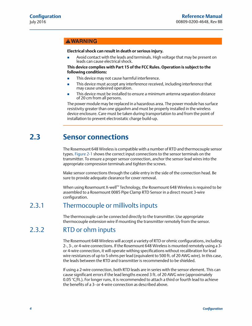
2.3 Sensor connections
The Rosemount 648 Wireless is compatible with a number of RTD and thermocouple sensor types. Figure 2-1 shows the correct input connections to the sensor terminals on the transmitter. To ensure a proper sensor connection, anchor the sensor lead wires into the appropriate compression terminals and tighten the screws.
Make sensor connections through the cable entry in the side of the connection head. Be sure to provide adequate clearance for cover removal.
When using Rosemount X-well™ Technology, the Rosemount 648 Wireless is required to be assembled to a Rosemount 0085 Pipe Clamp RTD Sensor in a direct mount 3-wire configuration.
2.3.1 Thermocouple or millivolts inputs
The thermocouple can be connected directly to the transmitter. Use appropriate thermocouple extension wire if mounting the transmitter remotely from the sensor.
2.3.2 RTD or ohm inputs
The Rosemount 648 Wireless will accept a variety of RTD or ohmic configurations, including 2-, 3-, or 4-wire connections. If the Rosemount 648 Wireless is mounted remotely using a 3- or 4-wire connection, it will operate withing specifications without recalibration for lead wire resistances of up to 5 ohms per lead (equivalent to 500 ft. of 20 AWG wire). In this case, the leads between the RTD and transmitter is recommended to be shielded.
If using a 2-wire connection, both RTD leads are in series with the sensor element. This can cause significant errors if the lead lengths exceed 3 ft. of 20 AWG wire (approximately 0.05 °C/ft.). For longer runs, it is recommended to attach a third or fourth lead to achieve the benefits of a 3- or 4-wire connection as described above.
Electrical shock can result in death or serious injury.
Avoid contact with the leads and terminals. High voltage that may be present on leads can cause electrical shock.
This device complies with Part 15 of the FCC Rules. Operation is subject to the following conditions:
This device may not cause harmful interference. This device must accept any interference received, including interference that
may cause undesired operation. This device must be installed to ensure a minimum antenna separation distance
of 20 cm from all persons.The power module may be replaced in a hazardous area. The power module has surface resistivity greater than one gigaohm and must be properly installed in the wireless device enclosure. Care must be taken during transportation to and from the point of installation to prevent electrostatic charge build-up.
4 Configuration

Reference Manual 00809-0200-4648, Rev BB
ConfigurationJuly 2016
Sensor lead wire resistance effect—RTD input
Since the lead wires are part of the RTD circuit, the lead wire resistance needs to be compensated for to achieve the best accuracy. This becomes especially critical in applications where long sensor and/or lead wires are used. There are three lead wire configurations commonly available.
A 4-wire design is ideal because the lead wire resistance is inconsequential to the measurement. It uses a measurement technique where a very small constant current of about 150 micro amps is applied to the sensor through two leads and the voltage developed across the sensor is measured over the other two wires with a high-impedance and high resolution measuring circuit. In accordance with Ohm's Law, the high impedance virtually eliminates any current flow in the voltage measurement leads and therefore the resistance of the leads is not a factor.
In a 3-wire configuration, compensation is accomplished using the third wire with the assumption that it will be the same resistance as the other two wires and the same compensation is applied to all three wires.
In a 2-wire configuration there can be no compensation for lead wire resistance since the lead wires are in series with the element and appear to the transmitter as part of the sensor's resistance causing inherent accuracy degradation.
Table 2-1. Examples of Approximate Basic Error
Sensor input Approximate basic error
4-wire RTD Negligible(1)
1. Independent of lead wire resistance up to 5 per lead.
3-wire RTD Error in reading is equivalent to unbalanced lead wire resistance(2)
2. Unbalanced lead wire resistance is the maximum resistance differences between any of two leads.
2-wire RTD Error in reading equivalent total lead wire resistance
5Configuration

Reference Manual00809-0200-4648, Rev BB
ConfigurationJuly 2016
Figure 2-1. Sensor Wiring
Figure 2-2. Rosemount 648 Wireless Sensor Connections
Note: Emerson™ Process Management provides 4-wire sensors for all single element RTDs. Use these RTDs in 3-wire configurations by leaving the unneeded leads disconnected and insulated with electrical tape.
Thermocouple/mV 4 Wire RTD and
3 Wire RTD and 2 Wire RTD and
1 2 3 4T/C and mV
1 2 3 44-wire RTD and
1 2 3 43-wire RTD and
1 2 3 42-wire RTD and
6 Configuration

Reference Manual 00809-0200-4648, Rev BB
ConfigurationJuly 2016
Lead wire configuration
Figure 2-3. Rosemount 68Q, 78 Standard Temperature Range, and 58C RTD Sensor
Figure 2-4. Rosemount 65, 78 High Temp, 68 RTD
Figure 2-5. Rosemount 183 Thermocouple
Single element
Single element
Type J Type E
Type K Type T
White (1)White (2)
Red (3)Red (4)
White (1)White (2)
Red (3)Red (4)
+ White (2)
– Red (3)
+ Purple (2)
– Red (3)
+ Yellow (2)
– Red (3)
+ Blue (2)
– Red (3)
7Configuration

Reference Manual00809-0200-4648, Rev BB
ConfigurationJuly 2016
Figure 2-6. Rosemount 185 Thermocouple
NoteWire color examples apply to Rosemount sensors, but will vary by manufacturer.
Sensor leads
If the sensor is installed in a high-voltage environment and a fault condition or installation error occurs, the sensor leads and transmitter terminals could carry lethal voltages. Use extreme caution when making contact with the leads and terminals.
Use the following steps to wire the sensor and supply power to the transmitter:
1. Remove the transmitter enclosure cover (if applicable).
2. Attach the sensor leads according to the wiring diagrams.
3. Connect the power module.
4. Verify the connection by observing the LCD display (if applicable).
5. Reattach and tighten the cover (if applicable).
2.4 Bench top configuration
Bench top configuration consists of testing the transmitter and verifying transmitter configuration data. The Rosemount 648 Wireless must be configured before installation, which may be performed either directly or remotely. Direct configuration can be performed using a Field Communicator, AMS Device Manager, AMS Wireless Configurator, or any WirelessHART® Communicator. Remote configuration can be performed using AMS Device Manager, AMS Wireless Configurator, or the Smart Wireless Gateway.
The power module must be installed to provide power to the Rosemount 648 Wireless for configuration. To communicate to the transmitter, begin by removing the power module-side housing cover, indicated as “Field terminals” by text located on the side of the device. This will expose the terminal block and HART® Communication terminals, which are labeled “COMM”. Connect the power module to supply power for configuration. See Figure 2-7.
Type J Type N
Type K
+ Black (2)
– White (3)
+ Pink (2)
– White (3)
+ Green (2)
– White (3)
8 Configuration

Reference Manual 00809-0200-4648, Rev BB
ConfigurationJuly 2016
Figure 2-7. Connection Diagram for Rosemount 648 Wireless and Field Communicator
2.4.1 Field Communicator
When performing device configuration directly, connect the bench equipment as shown in Figure 2-7 above, and turn on the field communicator by pressing the ON/OFF key. When using a Field Communicator, any configuration changes must be sent to the transmitter by using the Send key (F2).
The Field Communicator will search for a HART-compatible device and indicate when the connection is made. If the Field Communicator fails to connect, it will indicate that no device was found. If this occurs. refer to Section 6: Troubleshooting.
NoteFor HART Wireless transmitter communication via a Field Communicator, a Rosemount 648 Wireless Device Dashboard (DD) is required. Rosemount 648 Wireless Transmitters equipped with Rosemount X-well Technology requires DD revision 648 Dev. 4 Rev. 1 or higher to view Rosemount X-well functionality. To obtain the latest DD, visit the 475 Field Communicator System Software and Device Description site at:
EmersonProcess.com/Field-Communicator
2.4.2 AMS Device Manager and AMS Wireless Configurator
When configuring the Rosemount 648 Wireless using AMS Device Manager or AMS Wireless Configurator, double click the Rosemount 648 Wireless device icon (or right click and select Configure/Setup), then select the Configure/Setup tab. AMS Device Manager configuration changes are implemented when the Apply button is selected.
NoteFor HART Wireless transmitter communication via AMS, a Rosemount 648 Wireless Device Dashboard (DD) is required. Rosemount 648 Wireless Transmitters equipped with Rosemount X-well Technology requires DD revision 648 Dev. 4 Rev. 1 or higher to view Rosemount X-well functionality. To obtain the latest DD, visit the Emerson Process Management. Easy Upgrade site at:
EmersonProcess.com/Device-Install-Kits
COMM
P/N 00753-9200-0020
1
2
3
4
9Configuration

Reference Manual00809-0200-4648, Rev BB
ConfigurationJuly 2016
2.4.3 Smart Wireless Gateway
The Rosemount 648 Wireless supports limited remote configuration through the Smart Wireless Gateway. The Gateway allows configuration of the following device parameters: HART Tag, Short Tag, Descriptor, Engineering Units, Update Rate and Range Values.
2.4.4 Default settings
The Rosemount 648 Wireless default configuration is shown below:
NoteThe C1 option code can be used to enable factory configuration of the Update Rate, Date, Descriptor and Message fields. This code is not required to have the factory configure the Sensor Type, Connection or the Self Organizing Network parameters.
2.4.5 Device sensor configuration
Every temperature sensor has unique characteristics. In order to ensure the most accurate measurement, the Rosemount 648 Wireless should be configured to match the specific sensor that it will be connected to. Prior to installation, verify the configuration and connection settings of the temperature sensor through a Field Communicator or AMS Device Manager.
Sensor type Pt 100 ( =0.00385)
Engineering units °C
Number of lead wires 4
Network ID Factory generated network parameters
Join Key Factory generated network parameters
Update Rate 1 minute
10 Configuration
Reference Manual 00809-0200-4648, Rev BB
ConfigurationJuly 2016
11Configuration
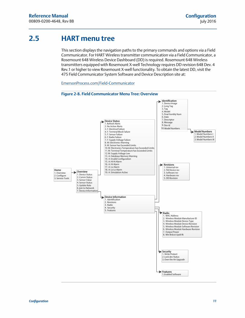
2.5 HART menu tree
This section displays the navigation paths to the primary commands and options via a Field Communicator. For HART Wireless transmitter communication via a Field Communicator, a Rosemount 648 Wireless Device Dashboard (DD) is required. Rosemount 648 Wireless transmitters equipped with Rosemount X-well Technology requires DD revision 648 Dev. 4 Rev.1 or higher to view Rosemount X-well functionality. To obtain the latest DD, visit the 475 Field Communicator System Software and Device Description site at:
EmersonProcess.com/Field-Communicator
Figure 2-8. Field Communicator Menu Tree: Overview
Reference Manual00809-0200-4648, Rev BB
ConfigurationJuly 2016
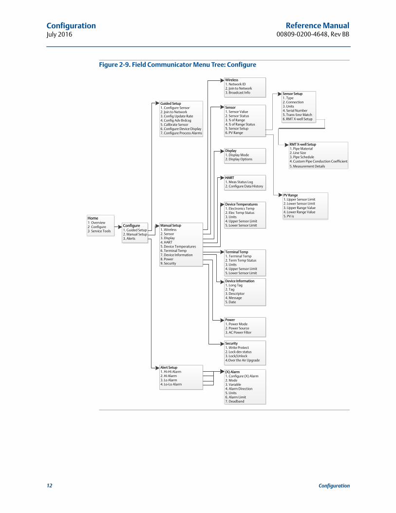
Figure 2-9. Field Communicator Menu Tree: Configure
12 Configuration
Reference Manual 00809-0200-4648, Rev BB
ConfigurationJuly 2016
13Configuration
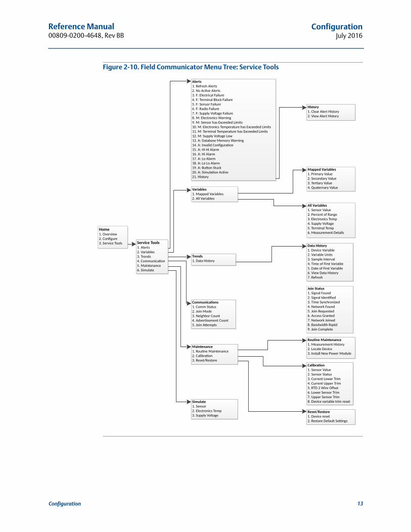
Figure 2-10. Field Communicator Menu Tree: Service Tools
�������������
���� ������
����������� �� ��������� ����������
�����������
���������
���� ������ �
!��"���������
#���������
����� ��
���"�$$�����������
���������������
������
���������������%�� �&
������������%�� �&
������
���'����%�� �&
���������
���( � ���"���������
��������� �
���(����)(��� ��
� ����
���(�*���+�������
���, ��� ���������
���-.�/���������-�����
���-.���������0� �1�-�����
!��-.����� ��-�����
#��-.�(�� �-�����
2��-.���$$�&�� ������-�����
3��".�/����� ����4�����
5��".����� ��+���/6�������7���
�8��".�/����� �������$��������+���/6�������7���
����".������������$��������+���/6�������7���
����".���$$�&�� ������7
�����.�'��������"�� �&�4�����
�����.�9������� ������ �
�!���.�%�%������
�#���.�%������
�2���.�7 ������
�3���.�7 �7 ������
�5���.�0�: ������1�
�8���.������ ���� ��
����%�� �&
�����������
���� ���������
���; ��" ��
���,��+� ��� ���
�������� �������� ���
!��; ���:��$��
��� ���
������� �
���/����� �������$
�����$$�&�� �����
�����������
���'������������
�����������<���
������$���9�������
������� *�-�����������
!��'���� *�-�����������
#�����'����%�� �&
2��(�*���+
����������������
���"�����������%�� �&
���7 �����'����
���9�������,��= ���" ����
�� ������
������� �������
������� ��������
�����������7 ������
�����������<$$������
!��(�'���4����>���
#��7 ������� �����
2��<$$������� �����
3��'����������������������
�������������
���'����������
���(��� ���'�*�������?���
������������ ��
���=����&������
������ ����&������
������ ��&������
���@��������&������
� ������ ��
������� �������
���=������� *�(����
���/����� �������$
�����$$�&�� �����
!�������������$
#��"�����������'�����
����������
���������- ���
���������9��� ���
��������&��+� �A��
���,�� �1�- ���
!��; ��(�B������
#���������C������
2��,�� �1�; ���
3��0�����+�(B���
5��; ��� �$����

Reference Manual00809-0200-4648, Rev BB
ConfigurationJuly 2016
14 Configuration
2.6 Basic setup
2.6.1 Configure sensor type
Every temperature sensor has unique characteristics to achieve the most accurate measurement. Configure the Rosemount 648 Wireless to match the specific sensor type.
1. Form the Home screen, select 2: Configure.
2. Select 1: Guided Setup
3. Select 1: Configure Sensor, then follow on the on-screen instructions to complete the configuration.
This method allows selection of the number of lead wires and temperature engineering units for the sensor.
2.6.2 Join device to network
To communicate with the Smart Wireless Gateway, and ultimately the host system, the transmitter must be configured to communicate over the wireless network. This step is the wireless equivalent of connecting wires from a transmitter to the host system.
1. From the Home screen, select 2: Configure.
2. Select 1: Guided Setup.
3. Select 2: Join to Network.
Using a Field Communicator or AMS Device Manager to communicate with the transmitter, enter the Network ID and Join Key so they match the Network ID and Join Key of the Smart Wireless Gateway and the other devices in the network. If the Network ID and Join Key are not identical to those set in the Gateway, the transmitter will not communicate with the network. The Network ID and Join Key may be obtained from the Smart Wireless Gateway on the System Settings>Network>Network Settings page of the Smart Wireless Gateway web based user interface.
Fast Keys 2, 1, 1
Fast key 2, 1, 2
Reference Manual 00809-0200-4648, Rev BB
ConfigurationJuly 2016
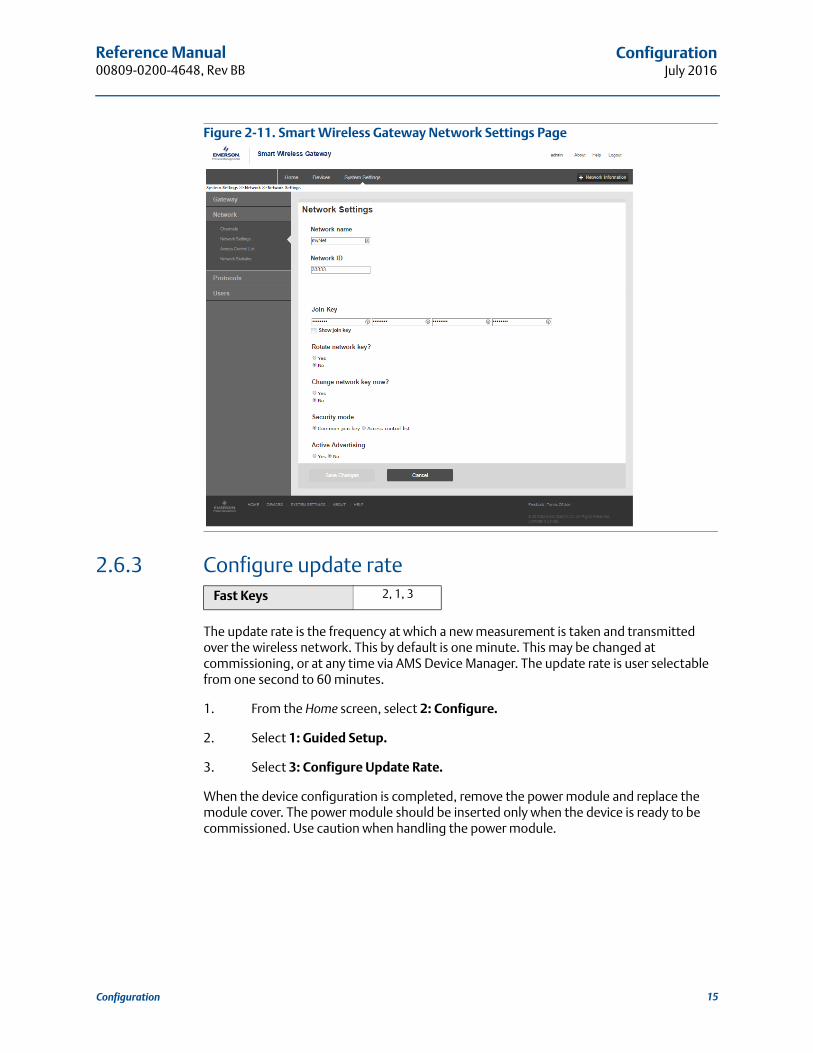
Figure 2-11. Smart Wireless Gateway Network Settings Page
2.6.3 Configure update rate
The update rate is the frequency at which a new measurement is taken and transmitted over the wireless network. This by default is one minute. This may be changed at commissioning, or at any time via AMS Device Manager. The update rate is user selectable from one second to 60 minutes.
1. From the Home screen, select 2: Configure.
2. Select 1: Guided Setup.
3. Select 3: Configure Update Rate.
When the device configuration is completed, remove the power module and replace the module cover. The power module should be inserted only when the device is ready to be commissioned. Use caution when handling the power module.
Fast Keys 2, 1, 3
15Configuration

Reference Manual00809-0200-4648, Rev BB
ConfigurationJuly 2016
Figure 2-12. Rosemount 648 Wireless Terminal Block
Connect the HART Communication leads to the COMM terminals on the terminal block.
Figure 2-13. Field Communicator Connections
COMM
P/N 00753-9200-0020
1
2
3
4
16 Configuration

Reference Manual 00809-0200-4648, Rev BB
ConfigurationJuly 2016
2.7 Fast Key sequence
Table 2-2 lists the Fast Key sequences for common transmitter functions.
NoteThe Fast Key sequences assumes that the latest Device Dashboard (DD) is being used. The latest DD revision can be found on the title page of this document.
2.8 Calibration
Calibrating the transmitter increases the measurement precision by allowing corrections to be made to the factory-stored characterization curve by digitally altering the transmitter’s interpretation of the sensor input.
To understand calibration, it is necessary to understand that smart transmitters operate differently from analog transmitters. An important difference is that smart transmitters are factory-characterized, meaning that they are shipped with a standard sensor curve stored in the transmitter firmware. In operation, the transmitter uses this information to produce a process variable output, in engineering units, dependent on the sensor input.
Calibration of the Rosemount 648 Wireless may include the following procedures:
Sensor Input Trim: digitally alter the transmitter’s interpretation of the input signal
Transmitter Sensor Matching: generates a special custom curve to match that specific sensor curve, as derived from the Callendar-Van Dusen constants
Table 2-2. Rosemount 648 Wireless Fast Key Sequence
Function Fast Key sequence Menu items
Device Information 2, 2, 7 Tag, Long Tag, Descriptor, Message, Date
Guided Setup 2, 1Configure Sensor, Join to Network, Config Advance Broadcasting, Calibrate Sensor
Manual Setup 2, 2Wireless, Sensor, Display, HART, Device Temperature, Terminal Temperature, Device Information, Power, Security
Wireless Configuration 2, 2, 1 Network ID, Join to Network, Broadcast Info
Sensor Configuration 2, 2, 2, 5
Type, Connection, Units, Serial Number, Transmitter-Sensor Matching, RMT X-well Setup
Sensor Calibration 3, 5, 2
Sensor Value, Sensor Status, Current Lower Trim, Current Upper Trim, RTD 2 Wire Offset, Lower Sensor Trim, Upper Sensor Trim, Device variable trim reset
17Configuration
Reference Manual00809-0200-4648, Rev BB
ConfigurationJuly 2016
2.8.1 Sensor input trim
Perform a sensor trim if the transmitters digital value for the primary variable does not match the plant’s standard calibration equipment. The sensor trim function calibrates the sensor to the transmitter in temperature units or raw units. Unless your site-standard input source is NIST-traceable, the trim functions will not maintain the NIST-traceability of the system.
The Sensor Input Trim command allows the transmitter’s interpretation of the input signal to be digitally altered. The sensor reference command trims, in engineering (F, C,R, K) or raw (, mV) units, the combined sensor and transmitter system to a site standard using a known temperature source. Sensor trimming is suitable for validation procedures or for applications that require calibrating the sensor and transmitter together.
Use the following procedure to perform a sensor trim with a Rosemount 648 Wireless:
1. Connect the calibration device or sensor to the transmitter. Refer to Figure 2-1 on page 6 or on the device terminal block for sensor wiring diagrams.
2. Connect the communicator to the transmitter.
3. From the Home screen, select 3 Service Tools> 5 Maintenance> 2 Calibration to prepare to trim the sensor.
4. Select 6 Lower Sensor Trim or 7 Upper Sensor Trim.
NoteIt is recommended to perform lower offset trims first, before performing upper slope trims.
5. Answer the question about using an active calibrator or not.
6. Adjust the calibration device to the desired trim value (must be within the selected sensor limits). If a combined sensor and transmitter system are being trimmed, expose the sensor to a known temperature and allow the temperature reading to stabilize. Use a bath, furnace or isothermal block, measured with a site-standard thermometer, as the known temperature source.
7. Select OK once the temperature stabilizes. The communicator displays the output value the transmitter associates with the input value provided by the calibration device.
8. Select the appropriate sensor trim units at the prompt.
9. Enter the trim point.
Fast Key sequence 3, 5, 2
18 Configuration

Reference Manual 00809-0200-4648, Rev BB
ConfigurationJuly 2016
2.8.2 Transmitter-sensor matching
Perform the transmitter-sensor matching procedure to enhance the temperature measurement accuracy of the system (see the comparison below) and if you have a sensor with Callendar-Van Dusen constants. When ordered from Emerson Process Management, sensors with Callendar-Van Dusen constants are NIST-traceable.
The Rosemount 648 Wireless accepts Callendar-Van Dusen constants from a calibrated RTD schedule and generates the actual curve to match that specific sensor curve.
1. The Actual Curve is identified from the Callendar-Van Dusen equation.
Total System Accuracy = ( Transmitter Accuracy)2 + (Sensor Accuracy)2
Callendar-Van Dusen equation
Rt = Ro + Ro [t - (0.01t-1)(0.01t) - (0.01t - 1)(0.01t)3]
The following input variables, included with specially-ordered Rosemount temperature sensors, are required:
Ro = Resistance at Ice PointAlpha = Sensor Specific ConstantBeta = Sensor Specific ConstantDelta = Sensor Specific Constant
Fast Key sequence 2, 1, 1
System accuracy comparison at 150 °C using a PT 100 (A=0.00385) RTD with a span of 0 to 200 °C
Standard RTD Matched RTD
Rosemount 648 Wireless ±0.45 °C Rosemount 648 Wireless ±0.45 °C
Standard RTD ±1.05 °C Matched RTD ±0.018 °C
Total System(1)
1. Calculated using root-summed-squared (RSS) statistical method.
±1.14 °C Total System(1) ±0.048 °C
Resi
stan
ce, O
hm
Temperature, C
Standard IEC 751 “Ideal” Curve(1)
Actual Curve
0 °C
19Configuration

Reference Manual00809-0200-4648, Rev BB
ConfigurationJuly 2016
To input Callendar-Van Dusen constants, perform the following procedure:
1. From the HOME screen, select 2 Configure, 1 Guided Setup, 1 Configure Sensor, 1 Configure Type and Units and press Enter.
2. Select Cal VanDusen at the Select Sensor Type prompt.
3. Select the appropriate number of wires at the Select Sensor Connection prompt.
4. Enter the Ro, Alpha, Delta, and Beta values from the stainless steel tag attached to the special-order sensor when prompted.
5. Select desired other options and select Enter.
6. To disable the Transmitter-sensor matching feature from the HOME screen select Configure>Guided Setup>Configure Sensor>Configure Sensor Type and Units and press Enter. Select the appropriate sensor type from the Select Sensor type prompt.
NoteWhen the transmitter-sensor matching is disabled, the transmitter reverts to factory trim. Make certain the transmitter engineering units default correctly before placing the transmitter into service.
2.9 Advanced setup
2.9.1 LCD display
The LCD display configuration command allows customization of the LCD display to suit application requirements. The LCD display will alternate between the selected items:
Temperature units
Sensor temperature
% of range
Supply voltage
Reference “LCD display screen messages” on page 43 for images of LCD display screens.
20 Configuration
Reference Manual 00809-0200-4648, Rev BB
ConfigurationJuly 2016
Enabling and configuring LCD display with a Field Communicator
From the Home screen. enter the Fast Key sequence:
Transmitter ordered with the LCD display will be shipped with display installed and enabled.
If the transmitter was ordered without the LCD display or if the LCD display was disabled, follow these steps to enable the LCD display on the transmitter.
1. From the Home screen, select 2: Configure.
2. Select 1: Guided Setup.
3. Select 6: Configure Device Display.
4. Select the option Periodic.
5. Select desired display options and select Enter.
Configuring LCD display with AMS Device Manager
Perform the following procedure:
1. Right click on the device and select Configure.
2. Select on Configure Device Display button under Optional Setup.
3. Select desired display options and select Enter.
NoteThe LCD display can be order as a spare part with part number: 00753-9004-0002.
Fast Keys 2, 1, 6
21Configuration
Reference Manual00809-0200-4648, Rev BB
ConfigurationJuly 2016
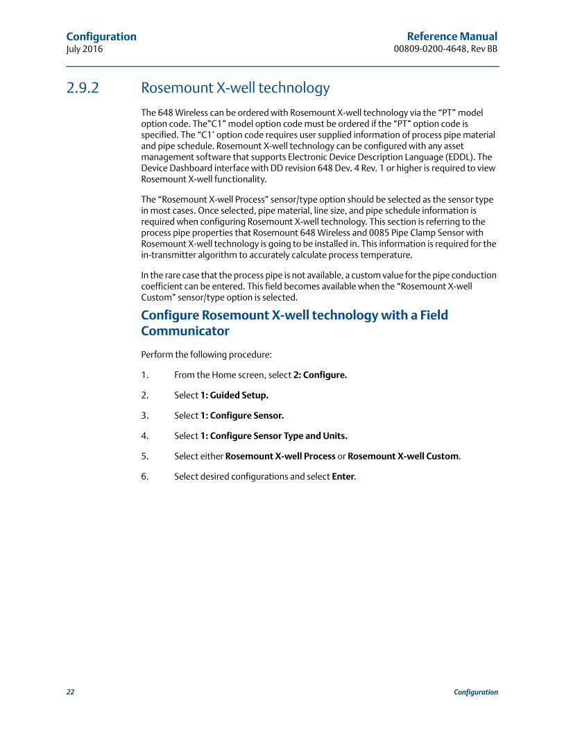
2.9.2 Rosemount X-well technology
The 648 Wireless can be ordered with Rosemount X-well technology via the “PT” model option code. The”C1” model option code must be ordered if the “PT” option code is specified. The “C1’ option code requires user supplied information of process pipe material and pipe schedule. Rosemount X-well technology can be configured with any asset management software that supports Electronic Device Description Language (EDDL). The Device Dashboard interface with DD revision 648 Dev. 4 Rev. 1 or higher is required to view Rosemount X-well functionality.
The “Rosemount X-well Process” sensor/type option should be selected as the sensor type in most cases. Once selected, pipe material, line size, and pipe schedule information is required when configuring Rosemount X-well technology. This section is referring to the process pipe properties that Rosemount 648 Wireless and 0085 Pipe Clamp Sensor with Rosemount X-well technology is going to be installed in. This information is required for the in-transmitter algorithm to accurately calculate process temperature.
In the rare case that the process pipe is not available, a custom value for the pipe conduction coefficient can be entered. This field becomes available when the “Rosemount X-well Custom” sensor/type option is selected.
Configure Rosemount X-well technology with a Field Communicator
Perform the following procedure:
1. From the Home screen, select 2: Configure.
2. Select 1: Guided Setup.
3. Select 1: Configure Sensor.
4. Select 1: Configure Sensor Type and Units.
5. Select either Rosemount X-well Process or Rosemount X-well Custom.
6. Select desired configurations and select Enter.
22 Configuration
Reference Manual 00809-0200-4648, Rev BB
ConfigurationJuly 2016
Configure Rosemount X-well technology with AMS Device Manager
Perform the following procedure:
1. Right click on the device and select Configure.
2. In the menu tree, select Manual Setup.
3. Select the Sensor tab.
4. Select either Rosemount X-well Process or Rosemount X-well Custom.
5. Select desired configurations and select Send.
Figure 2-14. Manual Setup - Sensor Screen for the Rosemount 648 Wireless with Rosemount X-well Technology
23Configuration
Reference Manual00809-0200-4648, Rev BB
ConfigurationJuly 2016
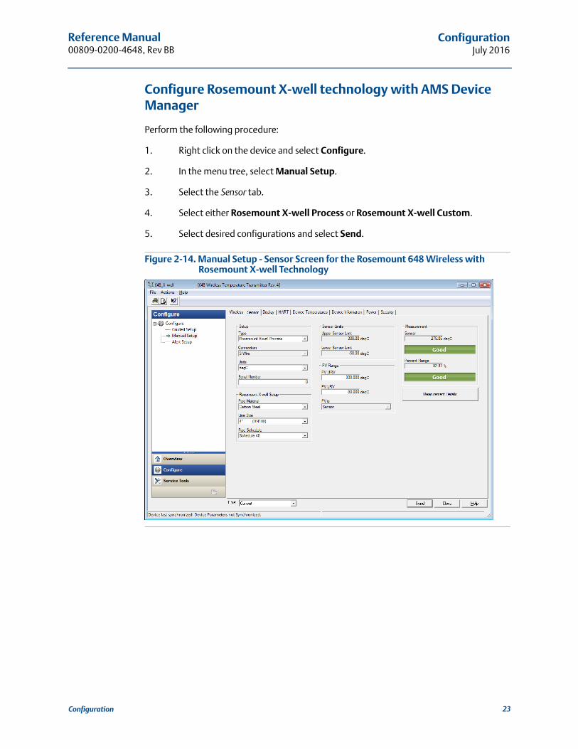
View Rosemount X-well measurement details
To view live data and trending for measured ambient temperature, measured surface temperature, and calculated process temperature, perform the following procedure:
1. Right click on the device and select Configure.
2. In the menu tree, select Manual Setup.
3. Select the Sensor tab.
4. Select the Measurement Details button.
Figure 2-15. Rosemount X-well Measurement Details Page
2.9.3 Process alerts
Process alerts allow the user to configure the transmitter to output a HART message when the configured data point is exceeded. An alert will be transmitter continuously if the set points are exceeded and the alert mode is ON. An alert will be displayed on a Field Communicator, AMS Device Manager status screen or in the error section of the LCD display. The alert will reset once the value returns within range.
NoteHI alert value must be higher than the LO alert value. Both alert values must be within the temperature sensor limits.
Fast Key sequence 2, 1, 7
24 Configuration

Reference Manual 00809-0200-4648, Rev BB
ConfigurationJuly 2016
Figure 2-16. Example 1: Rising Alert
Figure 2-17. Example 2: Falling Alert
Field Communicator
To configure the process alerts with a Field Communicator, perform the following procedure:
1. From the HOME screen, follow the Fast Key sequence, 2 Configure, 1 Guided Setup, 7 Configure Process Alarms.
2. Select 2 for Hi-Hi Alarm, orSelect 3 for Hi Alarm, orSelect 4 for LO Alarm, orSelect 5 for LO-LO Alarm and press Enter.
3. If the alarm is disabled, select 1 Enable and press Enter. If the alarm was previously enabled, select 2 Leave Enabled and press Enter.
4. Enter the alarm limit and press Enter.
5. Enter the alarm deadband and press Enter.
2.10 Remove power module
After the sensor and network have been configured, remove the power module and replace the transmitter cover. The power module should be inserted only when the device is ready to be commissioned. Use caution when handling the power module. The power module may be damaged if dropped from heights in excess of 20 feet.
Deadband
Assigned Value
Alert Set Point
Alert “OFF” Alert “ON” Alert “OFF”
Units o
f M
easure
ment
Time
Deadband
Assigned Value
Alert Set Point
Alert “OFF” Alert “ON” Alert “OFF”
Units o
f M
easure
ment
Time
25Configuration

26
Reference Manual00809-0200-4648, Rev BB
ConfigurationJuly 2016
Configuration

Reference Manual 00809-0200-4648, Rev BB
InstallationJuly 2016
Section 3 Installation
Overview . . . . . . . . . . . . . . . . . . . . . . . . . . . . . . . . . . . . . . . . . . . . . . . . . . . . . . . . . . . . . . . . page 27Safety messages . . . . . . . . . . . . . . . . . . . . . . . . . . . . . . . . . . . . . . . . . . . . . . . . . . . . . . . . . . page 27Wireless considerations . . . . . . . . . . . . . . . . . . . . . . . . . . . . . . . . . . . . . . . . . . . . . . . . . . . . page 28Physical installation . . . . . . . . . . . . . . . . . . . . . . . . . . . . . . . . . . . . . . . . . . . . . . . . . . . . . . . page 30LCD display . . . . . . . . . . . . . . . . . . . . . . . . . . . . . . . . . . . . . . . . . . . . . . . . . . . . . . . . . . . . . . . page 34Ground the transmitter . . . . . . . . . . . . . . . . . . . . . . . . . . . . . . . . . . . . . . . . . . . . . . . . . . . . page 35
3.1 Overview
The information in this section covers installation considerations. A Quick Start Guide is shipped with every transmitter to describe basic installation and startup procedures. Dimensional drawings for each Rosemount™ 648 Wireless variation and mounting configuration are included in Appendix A: Specifications and Reference Data.
3.2 Safety messages
Instructions and procedures in this section may require special precautions to ensure the safety of the personnel performing the operations. Information that potentially raises safety issues is indicated by a warning symbol ( ). Refer to the following safety messages before performing an operation preceded by this symbol.
Failure to follow these installation guidelines could result in death or serious injury.
Make sure only qualified personnel perform the installation.Explosions could result in death or serious injury.
Installation of this transmitter in an explosive environment must be in accordance with the appropriate local, national, and international standards, codes, and practices. Review the approvals section of the Rosemount 648 Wireless Temperature Transmitter Reference Manual for any restrictions associated with a safe installation.
Before connecting a Field Communicator in an explosive atmosphere, ensure the instruments are installed in accordance with intrinsically safe or non-incendive field wiring practices.
Process leaks may cause harm or result in death.
Install and tighten process connectors before applying pressure.
27Installation

Reference Manual00809-0200-4648, Rev BB
InstallationJuly 2016
3.3 Wireless considerations
3.3.1 Power up sequence
The Rosemount 648 Wireless and all other wireless devices should be installed only after the Smart Wireless Gateway (Gateway) has been installed and is functioning properly. Wireless devices should also be powered up in order of proximity from the Gateway, beginning with the closest. This will result in a simpler and faster network installation. Enable Active Advertising on the Gateway to ensure that new devices join the network faster. For more information see the Smart Wireless Gateway Reference Manual.
3.3.2 Antenna position
The antenna should be positioned vertically, either straight up or straight down, and it should be approximately 3 ft. (1 m) from any large structure, building, or conductive surface to allow for clear communication to other devices.
Figure 3-1. Antenna Position
Electrical shock can result in death or serious injury.
Avoid contact with the leads and terminals. High voltage that may be present on leads can cause electrical shock.
This device complies with Part 15 of the FCC Rules. Operation is subject to the following conditions:
This device may not cause harmful interference. This device must accept any interference received, including interference that
may cause undesired operation. This device must be installed to ensure a minimum antenna separation distance of
20 cm from all persons.The power module may be replaced in a hazardous area. The power module has surface resistivity greater than one gigaohm and must be properly installed in the wireless device enclosure. Care must be taken during transportation to and from the point of installation to prevent electrostatic charge build-up.
28 Installation
Reference Manual 00809-0200-4648, Rev BB
InstallationJuly 2016
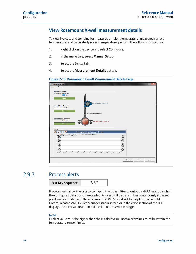
3.3.3 Conduit entry
Upon installation, ensure that each conduit entry is either sealed with a conduit plug using approved thread sealant, or has an installed conduit fitting or cable gland with appropriate threaded sealant.
Figure 3-2. Conduit Entry
A. Conduit entry
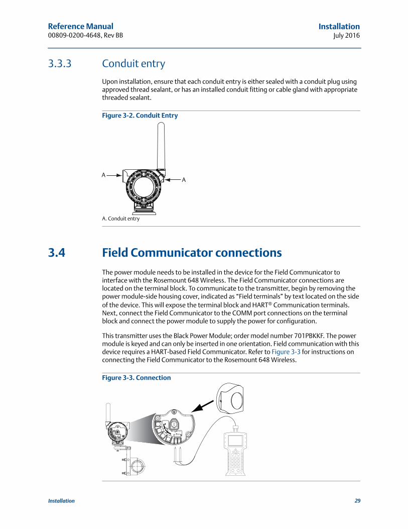
3.4 Field Communicator connections
The power module needs to be installed in the device for the Field Communicator to interface with the Rosemount 648 Wireless. The Field Communicator connections are located on the terminal block. To communicate to the transmitter, begin by removing the power module-side housing cover, indicated as “Field terminals” by text located on the side of the device. This will expose the terminal block and HART® Communication terminals. Next, connect the Field Communicator to the COMM port connections on the terminal block and connect the power module to supply the power for configuration.
This transmitter uses the Black Power Module; order model number 701PBKKF. The power module is keyed and can only be inserted in one orientation. Field communication with this device requires a HART-based Field Communicator. Refer to Figure 3-3 for instructions on connecting the Field Communicator to the Rosemount 648 Wireless.
Figure 3-3. Connection
AA
COMM
P/N 00753-9200-0020
1
2
3
4
29Installation

Reference Manual00809-0200-4648, Rev BB
InstallationJuly 2016
3.5 Physical installation
When selecting an installation location and position, consider the need for access to the mesh network, transmitter, and power module compartment for ease of power module replacement.
Verify the operating atmosphere of the transmitter is consistent with the appropriate hazardous locations certifications.
The Rosemount 648 Wireless can be installed in one of two configurations: Direct Mount, where the sensor is connected directly to the Rosemount 648 Wireless housing’s conduit entry, or Remote Mount, where the sensor is mounted separate from the Rosemount 648 Wireless housing, then connected to the Rosemount 648 Wireless via conduit. Select the installation sequence that corresponds to the mounting configuration.
Figure 3-4 provides an example of the relationship between transmitter housing temperature rise and extension length.
Figure 3-4. Rosemount 648 Wireless Connection Head Temperature Rise vs. Extension Length
Example
The transmitter specification limit is 85 °C. If the ambient temperature is 55 °C and the max process temperature to be measured is 815 °C, the maximum permissible connection head temperature rise is the transmitter specification limit minus the ambient temperature (moves 85 to 55 °C), or 30 °C.
In this case, a 5-in. extension meets this requirement, but a 6-in. extension provides an additional margin of thermowell protection, thereby reducing risk of ambient thermal damage.
Hou
sing
Tem
pera
ture
Ris
e, A
bove
Am
bien
t°C
(°F)
60 (108)
50 (90)
40 (72)
30 (54)
20 (36)
10 (18)
0
55
3 44.2
8765 9
815°C (1500 °F) Process Temperature
540°C (1000°F) Process Temperature
250°C (482°F) Process Temperature
Extension Length (in.)
30 Installation

Reference Manual 00809-0200-4648, Rev BB
InstallationJuly 2016
3.5.1 Direct mount
The direct mount installation should not be used when installing with a Swagelok® fitting.
1. Install the sensor/thermocouple according to standard installation practices. Be sure to use thread sealant on all connections.
2. Attach the Rosemount 648 Wireless housing to the sensor/thermocouple using the threaded conduit entry.
3. Attach the sensor/thermocouple wiring to the terminals as indicated on the wiring diagram.
4. Connect the power module if commissioning the device.
NoteUse caution when handling the power module. The power module may be damaged if dropped from heights exceeding 20 feet.
NoteWireless devices should be powered up after the Smart Wireless Gateway and in order of proximity from the Wireless Gateway, beginning with the closest device to the Gateway. This will result in a simpler and faster network installation.
5. Close the housing cover and tighten to safety specification. Always ensure a proper seal by installing the electronics housing covers so that metal touches metal, but do not over tighten.
6. Position the antenna vertically, typically straight up (antenna may be pointed straight down as well).
Table 3-1. Temperature Limits
Operating limit Storage limit
With LCD display–4 to 185 °F –40 to 185 °F
–20 to 85 °C –40 to 85 °C
Without LCD display–40 to 185 °F –40 to 185 °F
–40 to 85 °C –40 to 85 °C
31Installation
Reference Manual00809-0200-4648, Rev BB
InstallationJuly 2016
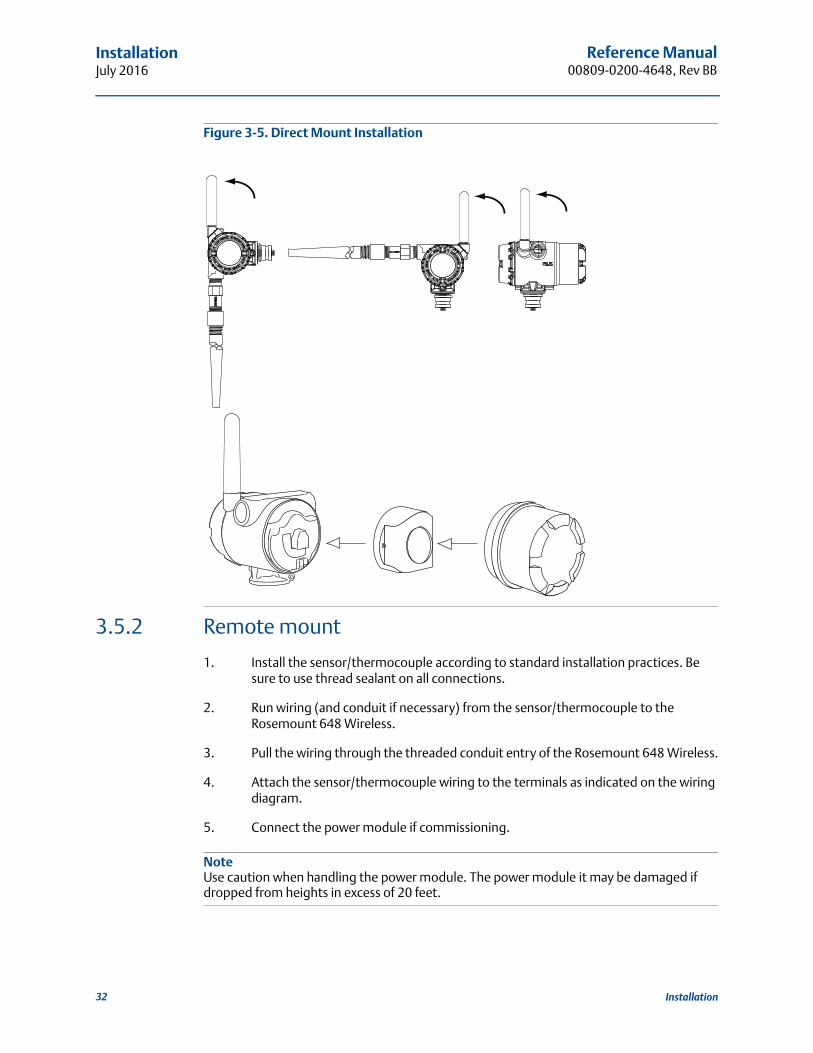
Figure 3-5. Direct Mount Installation
3.5.2 Remote mount
1. Install the sensor/thermocouple according to standard installation practices. Be sure to use thread sealant on all connections.
2. Run wiring (and conduit if necessary) from the sensor/thermocouple to the Rosemount 648 Wireless.
3. Pull the wiring through the threaded conduit entry of the Rosemount 648 Wireless.
4. Attach the sensor/thermocouple wiring to the terminals as indicated on the wiring diagram.
5. Connect the power module if commissioning.
NoteUse caution when handling the power module. The power module it may be damaged if dropped from heights in excess of 20 feet.
Possible antenna rotation shown.Antenna rotation allows for bestinstallation practices in anyconfiguration.
32 Installation

Reference Manual 00809-0200-4648, Rev BB
InstallationJuly 2016
NoteWireless devices should be powered up after the Smart Wireless Gateway and in order of proximity from the Wireless Gateway, beginning with the closest device to the Gateway. This will result in a simpler and faster network installation.
6. Close the housing cover and tighten to safety specification. Always ensure a proper seal by installing the electronics housing covers so that metal touches metal, but do not over tighten.
7. Position the antenna such that it is vertical, typically straight up (antenna may be pointed straight down as well).
Figure 3-6. Remote Mount Installation
33Installation

Reference Manual00809-0200-4648, Rev BB
InstallationJuly 2016
3.6 Rosemount X-well™ Installation
Rosemount X-well technology is only available in the Rosemount 648 Wireless and 0085 Pipe Clamp Sensor factory assembled compete point solution. Rosemount X-well technology will only work as specified with factory supplied and assembled pipe clamp sensor.
In general, pipe clamp sensor installation best practices shall be followed (see Rosemount Pipe Clamp Sensor Reference Manual) with Rosemount X-well technology specific requirements noted below:
1. Direct mounting of transmitter on pipe clamp sensor is required for Rosemount X-well Technology to properly function.
2. Transmitter head shall be placed away from dynamic external temperature sources such as a boiler.
3. Insulation (1/2-in. thick minimum) is required over the sensor clamp assembly and sensor extension up to transmitter head to prevent heat loss. Apply a minimum of six inches of insulation on each side of the pipe clamp sensor. Care should be taken to minimize air gaps between insulation and pipe. See Figure 3-7 below.
Note DO NOT apply insulation over transmitter head
4. Although it will come factory configured as such, ensure that pipe clamp RTD sensor is assembled in 3-wire configuration. See Figure 2-1 for more information.
Figure 3-7. Rosemount 648 Wireless with Rosemount X-well Technology Installation
3.7 LCD display
Transmitters ordered with the optional LCD display will be shipped with the display installed.
The LCD display can be rotated in 90 degree increments by squeezing the two tabs, pulling out, rotating and snapping back into place.
34 Installation

Reference Manual 00809-0200-4648, Rev BB
InstallationJuly 2016
If LCD display pins are inadvertently removed from the interface board, carefully re-insert the pins before snapping the LCD display back into place.
Use the following procedure and Figure 3-8 to install the LCD display:
1. Remove the LCD display cover. Do not remove the instrument covers in explosive environments when the circuit is live.
2. Put the 4-pin connector into the LCD display, rotate to the desired position and snap into place.
3. Replace the transmitter cover.
Note the following LCD display temperature limits:
Operating:–4 to 175 °F (–20 to 80 °C)
Storage:–40 to 185 °F (–40 to 85 °C)
NoteOnly use Rosemount Wireless LCD Display part number: 00753-9004-0002.
Figure 3-8. Optional LCD Display
A. LCD display pinsB. LCD displayC. LCD display cover
3.8 Ground the transmitter
The transmitter will operate with the housing either floating or grounded. However, the extra noise in floating systems affects many types of readout devices. If the signal appears noisy or erratic, grounding the transmitter at a single point may solve the problem.
The electronics enclosure should be grounded in accordance with local and national installation codes. This can be accomplished via the process connection, via the internal case grounding terminal, or via the external grounding terminal.
Thermocouple, mV, and RTD/Ohm inputs
Each process installation has different requirements for grounding. Use the grounding options recommended by the facility for the specific sensor type, or begin with grounding Option 1 (the most common).
A B C
35Installation

Reference Manual00809-0200-4648, Rev BB
InstallationJuly 2016
Option 1
1. Connect sensor wiring shield to the transmitter housing (only if the housing is grounded).
2. Ensure the transmitter housing is electrically isolated from the sensor wiring.
A. Sensor wiresB. TransmitterC. Shield ground point
Option 2
1. Ground sensor wiring shield at the sensor.
2. Ensure the sensor wiring and shield is electrically isolated from the transmitter housing.
A. Sensor wiresB. TransmitterC. Shield ground point
NoteAlways use facility recommended wiring practices.
A
B
C
A
B
C
36 Installation

Reference Manual 00809-0200-4648, Rev BB
CommissioningJuly 2016
Section 4 Commissioning
Overview . . . . . . . . . . . . . . . . . . . . . . . . . . . . . . . . . . . . . . . . . . . . . . . . . . . . . . . . . . . . . . . . page 37Safety messages . . . . . . . . . . . . . . . . . . . . . . . . . . . . . . . . . . . . . . . . . . . . . . . . . . . . . . . . . . page 37Verify operation . . . . . . . . . . . . . . . . . . . . . . . . . . . . . . . . . . . . . . . . . . . . . . . . . . . . . . . . . . page 38
4.1 Overview
The information in this section contains techniques to properly commissioning the device. A Rosemount™ 648 Quick Start Guide is shipped with every transmitter to describe basic installation and startup procedures.
4.2 Safety messages
Instructions and procedures in this section may require special precautions to ensure the safety of the personnel performing the operations. Information that potentially raises safety issues is indicated by a warning symbol ( ). Refer to the following safety messages before performing an operation preceded by this symbol.
Failure to follow these installation guidelines could result in death or serious injury.
Make sure only qualified personnel perform the installation.Explosions could result in death or serious injury.
Installation of this transmitter in an explosive environment must be in accordance with the appropriate local, national, and international standards, codes, and practices. Review the approvals section of the Rosemount 648 Wireless Temperature Transmitter Reference Manual for any restrictions associated with a safe installation.
Before connecting a Field Communicator in an explosive atmosphere, ensure the instruments are installed in accordance with intrinsically safe or non-incendive field wiring practices.
Process leaks may cause harm or result in death.
Install and tighten process connectors before applying pressure.
Electrical shock can result in death or serious injury.
Avoid contact with the leads and terminals. High voltage that may be present on leads can cause electrical shock.
37Commissioning

Reference Manual00809-0200-4648, Rev BB
CommissioningJuly 2016
NoteThe Rosemount 648 Wireless and all other wireless devices should be installed only after the Smart Wireless Gateway has been installed and is functioning properly. Wireless devices should also be powered up in order of proximity from the Smart Wireless Gateway, beginning with the closest device to the Gateway. This will result in a simpler and faster network installation.
4.3 Verify operation
The transmitter can be commissioned before or after installation. It may be useful to commission it on the bench, before installation, to ensure proper operation and to become familiar with its functionality. When applicable, make sure the instruments are installed in accordance with intrinsically safe or non-incendive field wiring practices. The device will be powered whenever the power module is installed. To avoid depleting the power module, make sure it is removed when the device is not in use.
Operation can be verified in four locations: at the device via the LCD display, using a Field Communicator, the Smart Wireless Gateway's integrated web interface, or using AMS™ Suite Wireless Communicator or AMS Device Manager.
4.3.1 LCD display
During normal operation, the LCD display will display the PV value at the wireless transmit rate up to as fast as one minute intervals. Refer to “LCD display screen messages” on page 43 for error codes and other LCD display messages. Press the Diagnostic button to display the TAG, Device ID, Network ID, Network Join Status and Device Status screens. For Device Status screens, see “LCD display screen messages” on page 43.
This device complies with Part 15 of the FCC Rules. Operation is subject to the following conditions:
This device may not cause harmful interference. This device must accept any interference received, including interference that
may cause undesired operation. This device must be installed to ensure a minimum antenna separation distance of
20 cm from all persons.The power module may be replaced in a hazardous area. The power module has surface resistivity greater than one gigaohm and must be properly installed in the wireless device enclosure. Care must be taken during transportation to and from the point of installation to prevent electrostatic charge build-up.
38 Commissioning
Reference Manual 00809-0200-4648, Rev BB
CommissioningJuly 2016
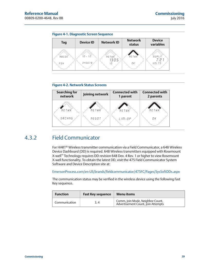
Figure 4-1. Diagnostic Screen Sequence
Figure 4-2. Network Status Screens
4.3.2 Field Communicator
For HART® Wireless transmitter communication via a Field Communicator, a 648 Wireless Device Dashboard (DD) is required. 648 Wireless transmitters equipped with Rosemount X-well™ Technology requires DD revision 648 Dev. 4 Rev. 1 or higher to view Rosemount X-well functionality. To obtain the latest DD, visit the 475 Field Communicator System Software and Device Description site at:
EmersonProcess.com/en-US/brands/fieldcommunicator/475FC/Pages/SysSoftDDs.aspx
The communication status may be verified in the wireless device using the following Fast Key sequence.
Tag Device ID Network IDNetwork
statusDevice
variables
Searching for network
Joining networkConnected with
1 parentConnected with
2 parents
Function Fast Key sequence Menu items
Communication 3, 4 Comm, Join Mode, Neighbor Count, Advertisement Count, Join Attempts
A b c d e
f g h
i d - 1 2
3 4 5 6 7 8
n e t w k
13 0 5 I D
n e t w k
O K
S u p l y
7. 2 1v o l t s
N E T w K
S R C H N G
n e t w k
N E G O T
n e t w k
L I M - O P
n e t w k
O K
39Commissioning
Reference Manual00809-0200-4648, Rev BB
CommissioningJuly 2016
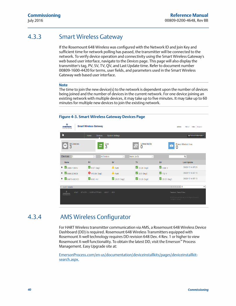
4.3.3 Smart Wireless Gateway
If the Rosemount 648 Wireless was configured with the Network ID and Join Key and sufficient time for network polling has passed, the transmitter will be connected to the network. To verify device operation and connectivity using the Smart Wireless Gateway's web based user interface, navigate to the Devices page. This page will also display the transmitter's tag, PV, SV, TV, QV, and Last Update time. Refer to document number 00809-1600-4420 for terms, user fields, and parameters used in the Smart Wireless Gateway web based user interface.
NoteThe time to join the new device(s) to the network is dependent upon the number of devices being joined and the number of devices in the current network. For one device joining an existing network with multiple devices, it may take up to five minutes. It may take up to 60 minutes for multiple new devices to join the existing network.
Figure 4-3. Smart Wireless Gateway Devices Page
4.3.4 AMS Wireless Configurator
For HART Wireless transmitter communication via AMS, a Rosemount 648 Wireless Device Dashboard (DD) is required. Rosemount 648 Wireless Transmitters equipped with Rosemount X-well technology requires DD revision 648 Dev. 4 Rev. 1 or higher to view Rosemount X-well functionality. To obtain the latest DD, visit the Emerson™ Process Management. Easy Upgrade site at:
EmersonProcess.com/en-us/documentation/deviceinstallkits/pages/deviceinstallkit-search.aspx.
40 Commissioning
Reference Manual 00809-0200-4648, Rev BB
CommissioningJuly 2016
Figure 4-4. AMS Wireless Configurator Explorer Window
41Commissioning

42
Reference Manual00809-0200-4648, Rev BB
CommissioningJuly 2016
Commissioning

Reference Manual 00809-0200-4648, Rev BB
Operation and MaintenanceJuly 2016
Section 5 Operation and Maintenance
LCD display screen messages . . . . . . . . . . . . . . . . . . . . . . . . . . . . . . . . . . . . . . . . . . . . . . . page 43Power module replacement . . . . . . . . . . . . . . . . . . . . . . . . . . . . . . . . . . . . . . . . . . . . . . . . .page 51
5.1 LCD display screen messages
5.1.1 Startup screen sequence
The following screens will display when the power module is first connected to theRosemount™ 648 Wireless Temperature Transmitter.
All Segments On: used to visually determine if there are any bad segments on the LCD display
Device Identification: used to determine Device Type
Device Information - Tag: user entered tag which is eight characters long - will not display if all characters are blank
X X X X X
X X X X x x xx x x x x x
6 4 8
W I r e l s
A b c d e
f g h
43Operation and Maintenance
Reference Manual00809-0200-4648, Rev BB
Operation and MaintenanceJuly 2016
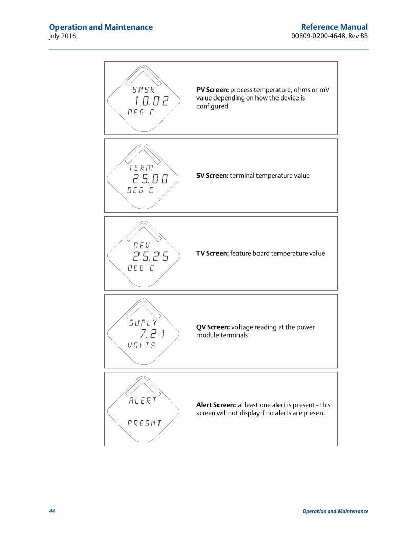
PV Screen: process temperature, ohms or mV value depending on how the device is configured
SV Screen: terminal temperature value
TV Screen: feature board temperature value
QV Screen: voltage reading at the power module terminals
Alert Screen: at least one alert is present - this screen will not display if no alerts are present
s n s r
1 0. 0 2d e g c
T E R M
2 5. 0 0d e g c
D E V
2 5. 2 5d e g c
S u p l y
7. 2 1v o l t s
a l e r t
p r e s n t
44 Operation and Maintenance

Reference Manual 00809-0200-4648, Rev BB
Operation and MaintenanceJuly 2016
5.1.2 Diagnostic button screen sequence
The following five screens will display when the device is operating properly and the Diagnostic Button has been pressed.
Device Information - Tag: user entered tag which is 8 characters long - will not display if all characters are blank
Device Identification: used to determine Device ID
Diagnostic Button Screen 3: assuming the device has the correct join key, this ID tells the user what network the device can connect with
Diagnostic Button Screen 4.11: the device has joined a network and has been fully configured and has multiple parents
Diagnostic Button Screen 5: voltage reading at the power module terminals
A b c d e
f g h
i d - 1 2
3 4 5 6 7 8
n e t w k
13 0 5 I D
n e t w k
O K
S u p l y
7. 2 1v o l t s
45Operation and Maintenance
Reference Manual00809-0200-4648, Rev BB
Operation and MaintenanceJuly 2016
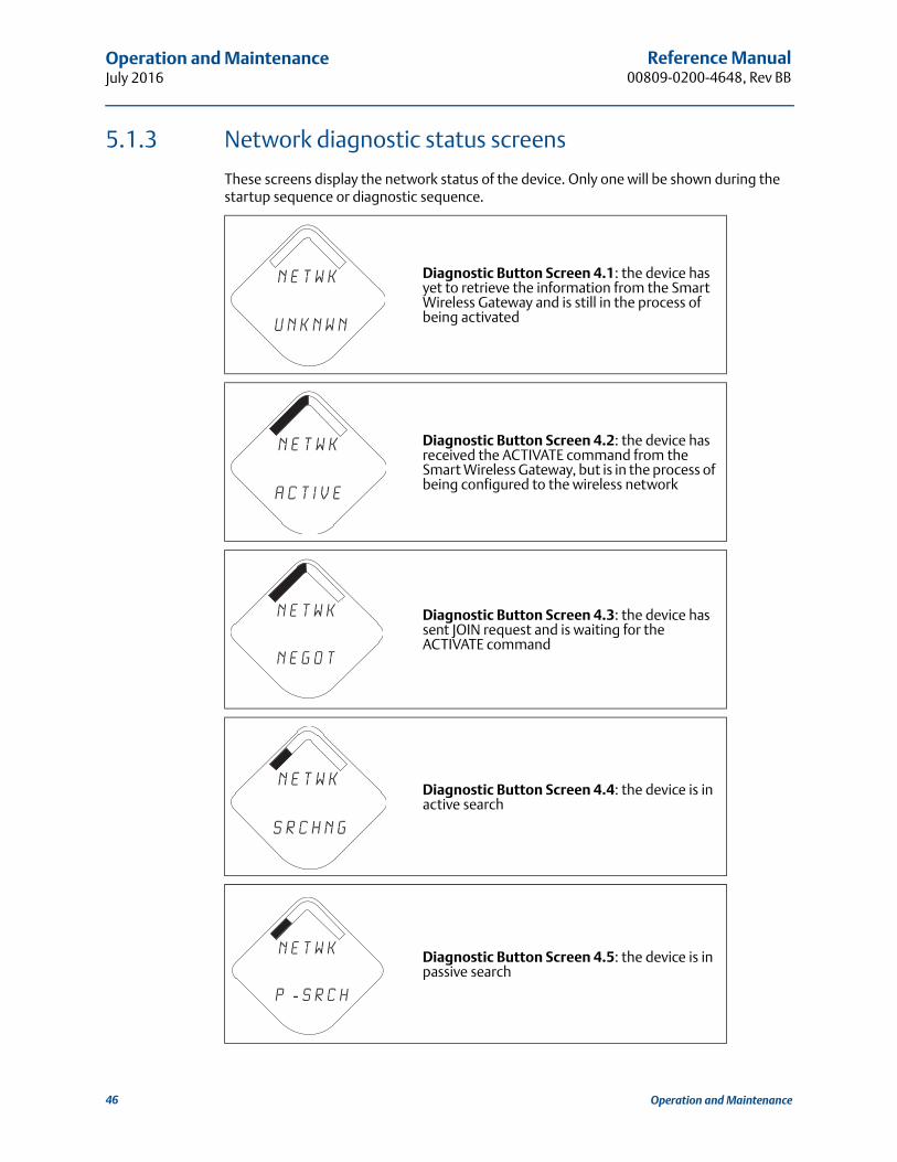
5.1.3 Network diagnostic status screens
These screens display the network status of the device. Only one will be shown during the startup sequence or diagnostic sequence.
Diagnostic Button Screen 4.1: the device has yet to retrieve the information from the Smart Wireless Gateway and is still in the process of being activated
Diagnostic Button Screen 4.2: the device has received the ACTIVATE command from the Smart Wireless Gateway, but is in the process of being configured to the wireless network
Diagnostic Button Screen 4.3: the device has sent JOIN request and is waiting for the ACTIVATE command
Diagnostic Button Screen 4.4: the device is in active search
Diagnostic Button Screen 4.5: the device is in passive search
n e t w k
u n k n w n
n e t w k
a c t i v e
n e t w k
N E G O T
N E T w K
S R C H N G
n e t w k
p - s r c h
46 Operation and Maintenance

Reference Manual 00809-0200-4648, Rev BB
Operation and MaintenanceJuly 2016
Diagnostic Button Screen 4.6: the device couldn’t find the network and is in deep sleep mode to preserve power module life
Diagnostic Button Screen 4.7: the device synchronized to a network
Diagnostic Button Screen 4.8: the device will reset
Diagnostic Button Screen 4.9: the device couldn’t join because of dropped packets and will reset
Diagnostic Button Screen 4.10: the device has joined a network and has been fully configured but has only one parent device
n e t w k
i d l e
n e t w k
c o n e c t
n e t w k
r e s e t
n e t w k
b c k o f f
n e t w k
L I M - O P
47Operation and Maintenance
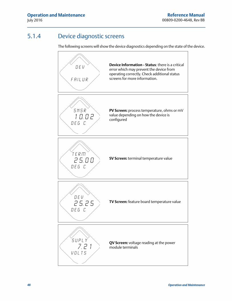
Reference Manual00809-0200-4648, Rev BB
Operation and MaintenanceJuly 2016
5.1.4 Device diagnostic screens
The following screens will show the device diagnostics depending on the state of the device.
Device Information - Status: there is a critical error which may prevent the device from operating correctly. Check additional status screens for more information.
PV Screen: process temperature, ohms or mV value depending on how the device is configured
SV Screen: terminal temperature value
TV Screen: feature board temperature value
QV Screen: voltage reading at the power module terminals
D E V
f A i l u r
s n s r
1 0. 0 2d e g c
T E R M
2 5. 0 0d e g c
D E V
2 5. 2 5d e g c
S u p l y
7. 2 1v o l t s
48 Operation and Maintenance
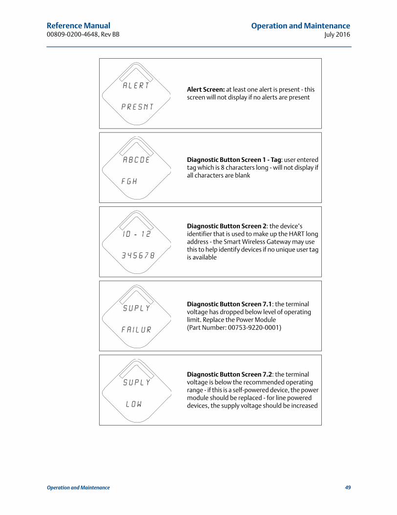
Reference Manual 00809-0200-4648, Rev BB
Operation and MaintenanceJuly 2016
Alert Screen: at least one alert is present - this screen will not display if no alerts are present
Diagnostic Button Screen 1 - Tag: user entered tag which is 8 characters long - will not display if all characters are blank
Diagnostic Button Screen 2: the device’s identifier that is used to make up the HART long address - the Smart Wireless Gateway may use this to help identify devices if no unique user tag is available
Diagnostic Button Screen 7.1: the terminal voltage has dropped below level of operating limit. Replace the Power Module(Part Number: 00753-9220-0001)
Diagnostic Button Screen 7.2: the terminal voltage is below the recommended operating range - if this is a self-powered device, the power module should be replaced - for line powered devices, the supply voltage should be increased
a l e r t
p r e s n t
A b c d e
f g h
i d - 1 2
3 4 5 6 7 8
s u p l y
f a i l u r
s u p l y
l o w
49Operation and Maintenance
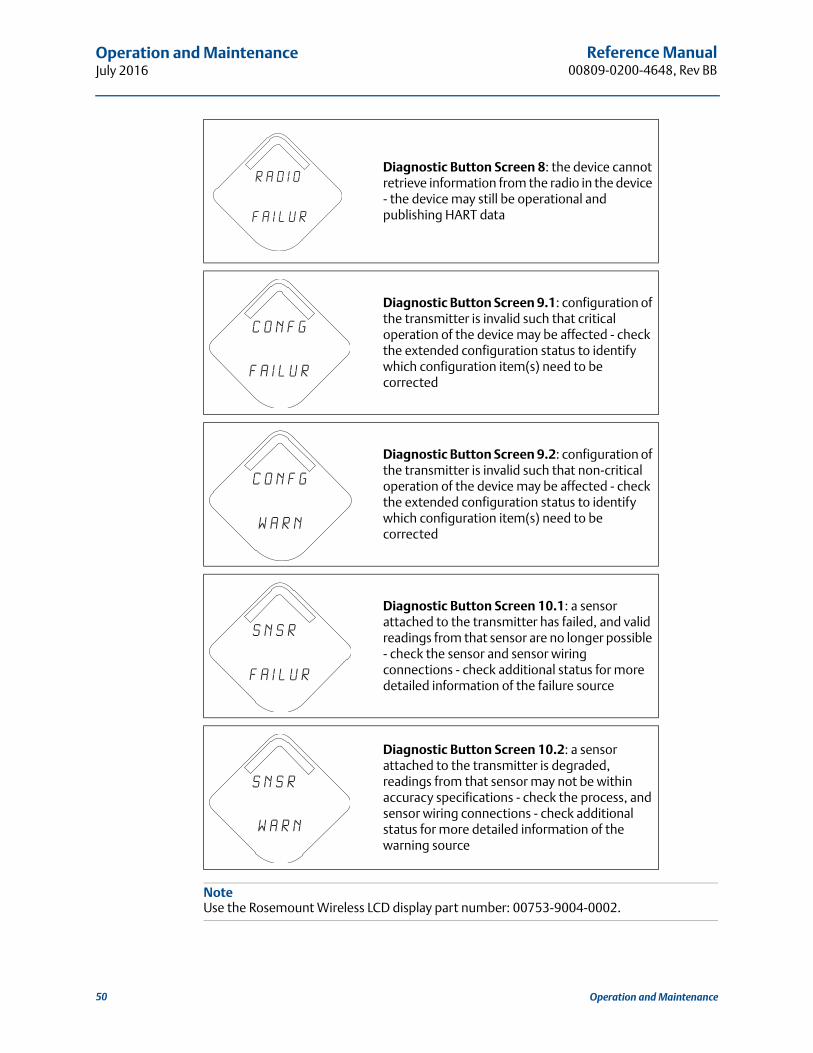
Reference Manual00809-0200-4648, Rev BB
Operation and MaintenanceJuly 2016
NoteUse the Rosemount Wireless LCD display part number: 00753-9004-0002.
Diagnostic Button Screen 8: the device cannot retrieve information from the radio in the device - the device may still be operational and publishing HART data
Diagnostic Button Screen 9.1: configuration of the transmitter is invalid such that critical operation of the device may be affected - check the extended configuration status to identify which configuration item(s) need to be corrected
Diagnostic Button Screen 9.2: configuration of the transmitter is invalid such that non-critical operation of the device may be affected - check the extended configuration status to identify which configuration item(s) need to be corrected
Diagnostic Button Screen 10.1: a sensor attached to the transmitter has failed, and valid readings from that sensor are no longer possible - check the sensor and sensor wiring connections - check additional status for more detailed information of the failure source
Diagnostic Button Screen 10.2: a sensor attached to the transmitter is degraded, readings from that sensor may not be within accuracy specifications - check the process, and sensor wiring connections - check additional status for more detailed information of the warning source
r a d i o
f a i l u r
c o n f g
f a i l u r
c o n f g
w a r n
s n s r
f a i l u r
s n s r
w a r n
50 Operation and Maintenance

Reference Manual 00809-0200-4648, Rev BB
Operation and MaintenanceJuly 2016
5.2 Power module replacement
Expected power module life is 10 years at reference conditions.(1)
When power module replacement is required, remove the power module cover on the field terminal side and remove the power module. Replace the power module (part number 00753-9220-0001) and replace the cover. Tighten to specification and verify operation.
Handling considerations
Each power module with the wireless unit contains two “C” size primary lithium/thionyl chloride batteries. Each battery contains approximately 2.5 grams of lithium, for a total of 5 grams in each pack. Under normal conditions, the battery materials are self-contained and are not reactive as long as the batteries and the power module integrity are maintained. Care should be taken to prevent thermal, electrical or mechanical damage. Contacts should be protected to prevent premature discharge.
Use caution when handling the Power Module, it may damaged if dropped from heights in excess of 20 feet.
Battery hazards remain when cells are discharged.
Power modules should be stored in a clean and dry area. For maximum power module life, storage temperature should not exceed 30 °C.
Environmental considerations
As with any battery, local environmental rules and regulations should be consulted for proper management of spent batteries. If no specific requirements exist, recycling through a qualified recycler is encouraged. Consult the materials safety data sheet for battery specific information.
Shipping considerations
The unit is shipped to you without the power module installed. Unless specifically instructed to do otherwise, remove the power module from the unit prior to shipping.
The unit was shipped to you without the power module installed. Remove the power module prior to shipping.
Each power module contains two “C” size primary lithium batteries. Primary lithium batteries are regulated in transportation by the U. S. Department of Transportation, and are also covered by IATA (International Air Transport Association), ICAO (International Civil Aviation Organization), and ARD (European Ground Transportation of Dangerous Goods). It is the responsibility of the shipper to ensure compliance with these or any other local requirements. Consult current regulations and requirements before shipping.
1. Reference conditions are 70 °F (21 °C), transmit rate of once per minute, and routing data for three additional network devices.
51Operation and Maintenance

Reference Manual00809-0200-4648, Rev BB
Operation and MaintenanceJuly 2016
52 Operation and Maintenance
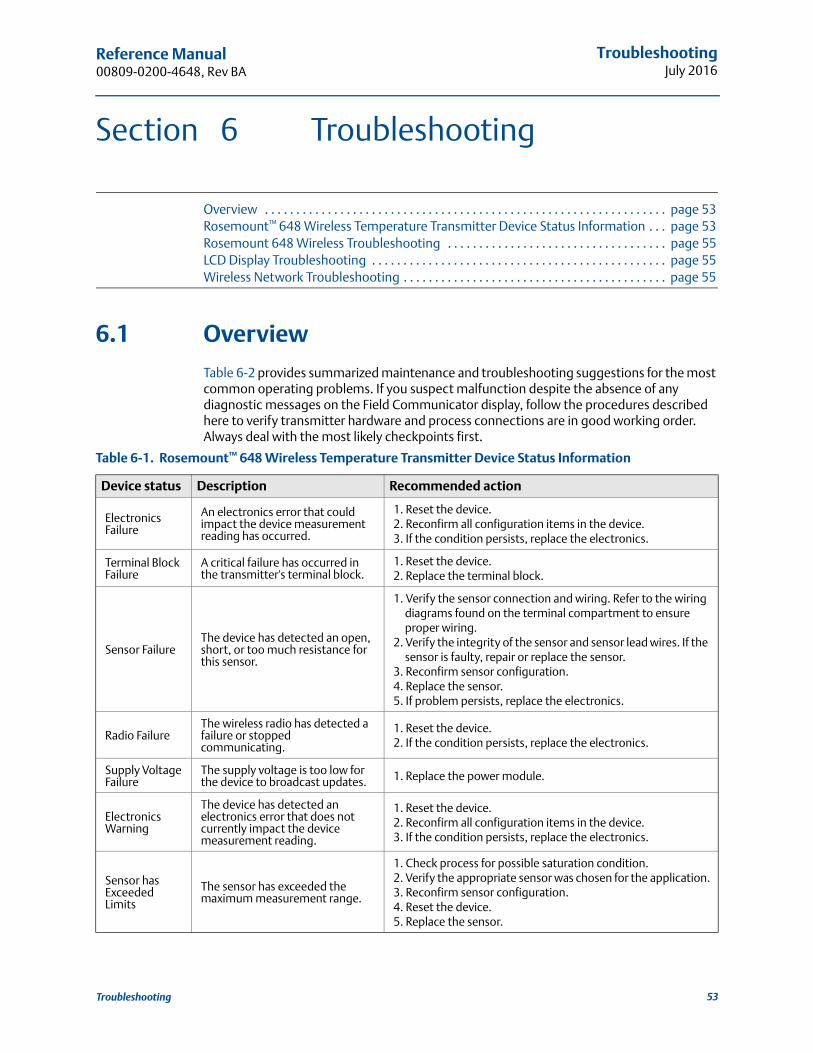
Reference Manual 00809-0200-4648, Rev BA
TroubleshootingJuly 2016
Section 6 Troubleshooting
Overview . . . . . . . . . . . . . . . . . . . . . . . . . . . . . . . . . . . . . . . . . . . . . . . . . . . . . . . . . . . . . . . . page 53Rosemount™ 648 Wireless Temperature Transmitter Device Status Information . . . page 53Rosemount 648 Wireless Troubleshooting . . . . . . . . . . . . . . . . . . . . . . . . . . . . . . . . . . . page 55LCD Display Troubleshooting . . . . . . . . . . . . . . . . . . . . . . . . . . . . . . . . . . . . . . . . . . . . . . . page 55Wireless Network Troubleshooting . . . . . . . . . . . . . . . . . . . . . . . . . . . . . . . . . . . . . . . . . . page 55
6.1 Overview
Table 6-2 provides summarized maintenance and troubleshooting suggestions for the most common operating problems. If you suspect malfunction despite the absence of any diagnostic messages on the Field Communicator display, follow the procedures described here to verify transmitter hardware and process connections are in good working order. Always deal with the most likely checkpoints first.
Table 6-1. Rosemount™ 648 Wireless Temperature Transmitter Device Status Information
Device status Description Recommended action
Electronics Failure
An electronics error that could impact the device measurement reading has occurred.
1. Reset the device.2. Reconfirm all configuration items in the device.3. If the condition persists, replace the electronics.
Terminal Block Failure
A critical failure has occurred in the transmitter's terminal block.
1. Reset the device.2. Replace the terminal block.
Sensor FailureThe device has detected an open, short, or too much resistance for this sensor.
1. Verify the sensor connection and wiring. Refer to the wiring diagrams found on the terminal compartment to ensure proper wiring.
2. Verify the integrity of the sensor and sensor lead wires. If the sensor is faulty, repair or replace the sensor.
3. Reconfirm sensor configuration.4. Replace the sensor.5. If problem persists, replace the electronics.
Radio FailureThe wireless radio has detected a failure or stopped communicating.
1. Reset the device.2. If the condition persists, replace the electronics.
Supply Voltage Failure
The supply voltage is too low for the device to broadcast updates. 1. Replace the power module.
Electronics Warning
The device has detected an electronics error that does not currently impact the device measurement reading.
1. Reset the device.2. Reconfirm all configuration items in the device.3. If the condition persists, replace the electronics.
Sensor has Exceeded Limits
The sensor has exceeded the maximum measurement range.
1. Check process for possible saturation condition.2. Verify the appropriate sensor was chosen for the application.3. Reconfirm sensor configuration.4. Reset the device.5. Replace the sensor.
53Troubleshooting
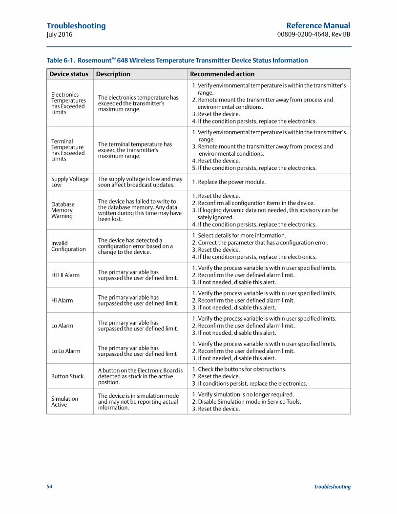
Reference Manual00809-0200-4648, Rev BB
TroubleshootingJuly 2016
Electronics Temperatures has Exceeded Limits
The electronics temperature has exceeded the transmitter's maximum range.
1. Verify environmental temperature is within the transmitter’s range.
2. Remote mount the transmitter away from process and environmental conditions.
3. Reset the device.4. If the condition persists, replace the electronics.
Terminal Temperature has Exceeded Limits
The terminal temperature has exceed the transmitter's maximum range.
1. Verify environmental temperature is within the transmitter’s range.
3. Remote mount the transmitter away from process and environmental conditions.
4. Reset the device.5. If the condition persists, replace the electronics.
Supply Voltage Low
The supply voltage is low and may soon affect broadcast updates. 1. Replace the power module.
Database Memory Warning
The device has failed to write to the database memory. Any data written during this time may have been lost.
1. Reset the device.2. Reconfirm all configuration items in the device.3. If logging dynamic data not needed, this advisory can be
safely ignored.4. If the condition persists, replace the electronics.
Invalid Configuration
The device has detected a configuration error based on a change to the device.
1. Select details for more information.2. Correct the parameter that has a configuration error.3. Reset the device.4. If the condition persists, replace the electronics.
HI HI Alarm The primary variable has surpassed the user defined limit.
1. Verify the process variable is within user specified limits.2. Reconfirm the user defined alarm limit.3. If not needed, disable this alert.
HI Alarm The primary variable has surpassed the user defined limit.
1. Verify the process variable is within user specified limits.2. Reconfirm the user defined alarm limit.3. If not needed, disable this alert.
Lo Alarm The primary variable has surpassed the user defined limit.
1. Verify the process variable is within user specified limits.2. Reconfirm the user defined alarm limit.3. If not needed, disable this alert.
Lo Lo Alarm The primary variable has surpassed the user defined limit
1. Verify the process variable is within user specified limits.2. Reconfirm the user defined alarm limit.3. If not needed, disable this alert.
Button StuckA button on the Electronic Board is detected as stuck in the active position.
1. Check the buttons for obstructions.2. Reset the device.3. If conditions persist, replace the electronics.
Simulation Active
The device is in simulation mode and may not be reporting actual information.
1. Verify simulation is no longer required.2. Disable Simulation mode in Service Tools.3. Reset the device.
Table 6-1. Rosemount™ 648 Wireless Temperature Transmitter Device Status Information
Device status Description Recommended action
54 Troubleshooting
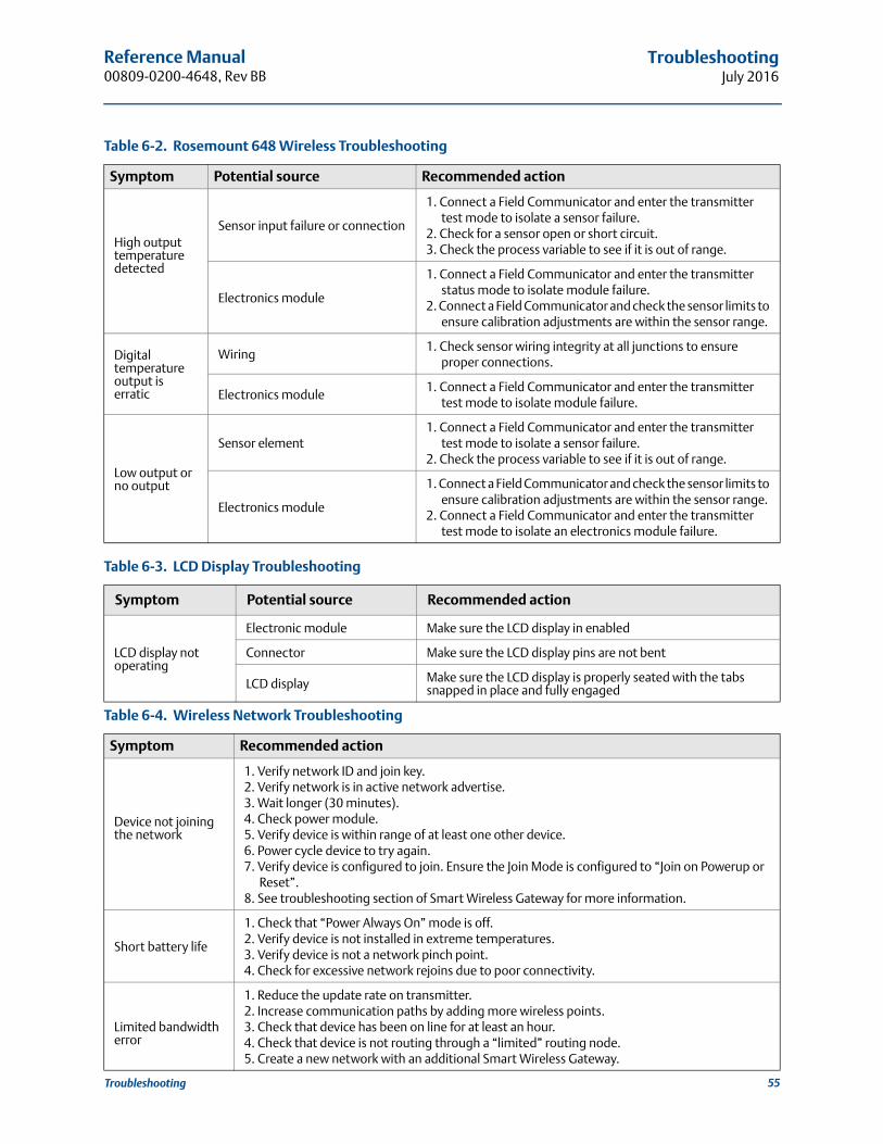
Reference Manual 00809-0200-4648, Rev BB
TroubleshootingJuly 2016
55Troubleshooting
Table 6-2. Rosemount 648 Wireless Troubleshooting
Symptom Potential source Recommended action
High output temperature detected
Sensor input failure or connection
1. Connect a Field Communicator and enter the transmitter test mode to isolate a sensor failure.
2. Check for a sensor open or short circuit.3. Check the process variable to see if it is out of range.
Electronics module
1. Connect a Field Communicator and enter the transmitter status mode to isolate module failure.
2. Connect a Field Communicator and check the sensor limits to ensure calibration adjustments are within the sensor range.
Digital temperature output is erratic
Wiring1. Check sensor wiring integrity at all junctions to ensure
proper connections.
Electronics module1. Connect a Field Communicator and enter the transmitter
test mode to isolate module failure.
Low output or no output
Sensor element1. Connect a Field Communicator and enter the transmitter
test mode to isolate a sensor failure.2. Check the process variable to see if it is out of range.
Electronics module
1. Connect a Field Communicator and check the sensor limits to ensure calibration adjustments are within the sensor range.
2. Connect a Field Communicator and enter the transmitter test mode to isolate an electronics module failure.
Table 6-3. LCD Display Troubleshooting
Symptom Potential source Recommended action
LCD display not operating
Electronic module Make sure the LCD display in enabled
Connector Make sure the LCD display pins are not bent
LCD display Make sure the LCD display is properly seated with the tabs snapped in place and fully engaged
Table 6-4. Wireless Network Troubleshooting
Symptom Recommended action
Device not joining the network
1. Verify network ID and join key.2. Verify network is in active network advertise.3. Wait longer (30 minutes).4. Check power module.5. Verify device is within range of at least one other device.6. Power cycle device to try again.7. Verify device is configured to join. Ensure the Join Mode is configured to “Join on Powerup or
Reset”.8. See troubleshooting section of Smart Wireless Gateway for more information.
Short battery life
1. Check that “Power Always On” mode is off.2. Verify device is not installed in extreme temperatures.3. Verify device is not a network pinch point.4. Check for excessive network rejoins due to poor connectivity.
Limited bandwidth error
1. Reduce the update rate on transmitter.2. Increase communication paths by adding more wireless points.3. Check that device has been on line for at least an hour.4. Check that device is not routing through a “limited” routing node.5. Create a new network with an additional Smart Wireless Gateway.

Reference Manual00809-0200-4648, Rev BB
TroubleshootingJuly 2016
56 Troubleshooting
Specifications and Reference DataJuly 2016
Reference Manual00809-0200-4648, Rev BB
Appendix A Specifications and Reference Data
Specifications . . . . . . . . . . . . . . . . . . . . . . . . . . . . . . . . . . . . . . . . . . . . . . . . . . . . . . . . . . . . page 57Dimensional drawings . . . . . . . . . . . . . . . . . . . . . . . . . . . . . . . . . . . . . . . . . . . . . . . . . . . . . page 63Ordering information . . . . . . . . . . . . . . . . . . . . . . . . . . . . . . . . . . . . . . . . . . . . . . . . . . . . . . page 66
A.1 Specifications
A.1.1 Functional specifications
Input
Supports thermocouple, RTD, millivolt and ohm input types. See “Accuracy” on page 59 for sensor options.
Output
Wireless enabled, linear with temperature or input.
Local display
The optional five-digit integral LCD display can display engineering units (°F, °C, °R, K, , and millivolts). Display updates at transmit rate up to once per minute.
Humidity limits
0–99% relative humidity
Update rate
WirelessHART®, user-selectable, 1 second to 60 minutes
Accuracy
(Pt 100 @ reference conditions: 20 °C)
±0.225 °C (±0.405 °F)
Radio frequency power output from antenna
Long Range (WK1 option) antenna: Maximum of 10 mW (10 dBm) EIRP
A.1.2 Physical specifications
Electrical connections
Power moduleThe SmartPower™ Long Life Power Module from Emerson™ Process Management is field replaceable, featuring keyed connections that eliminate the risk of incorrect installation.
The power module is an Intrinsically Safe solution, containing Lithium-thionyl chloride with a polybutadine terephthalate (PBT) enclosure.
The Rosemount™ 648 Wireless Temperature Transmitter has power module life time rating of 10 years with a one-minute update rate, at reference conditions.(1)
Sensor terminalsSensor terminals permanently fixed to terminal block
Field Communicator connectionsClips permanently fixed to terminal block, designated by the text “COMM.”
Materials of construction
HousingLow-copper aluminum
Paint Polyurethane
Cover O-ringBuna-N
Terminal block and power modulePBT
AntennaPBT/PC integrated omni-directional antenna
1. Reference conditions are 70 °F (21 °C), and routing data for three additional network devices. Continuous exposure to ambient temperature limits (-40 °F or 185 °F; -40 °C or 85 °C) may reduce specified life by less than 20 percent.
57Specifications and Reference Data

Specifications and Reference DataJuly 2016
Reference Manual 00809-0200-4648, Rev BB
Mounting
Transmitters may be attached directly to the sensor. Mounting brackets also permit remote mounting. See “Dimensional drawings” on page 63.
Weight
Low-copper aluminumRosemount 648 Wireless without LCD display- 4.6 lbs. (2 kg)Rosemount 648 Wireless with M5 LCD display- 4.7 lbs (2.1 kg)
Stainless steelRosemount 648 Wireless without LCD display- 8.0 lbs. (3.6 kg)Rosemount 648 Wireless with M5 LCD display- 8.1 lbs (3.7 kg)
Enclosure ratings (Rosemount 648 Wireless)
Housing Style option codes D and E are Type 4X and IP66/67 rated dual-compartment housings.
A.1.3 Performance specifications
EMC (ElectroMagnetic Compatibility)All Models:
Meets all relevant requirements of EN 61326-1; 2006; EN 61326-2-3; 2006
Transmitter measurement stability
The Rosemount 648 Wireless has a stability of ±0.15% of output reading or 0.15 °C (whichever is greater) for 24 months.
Self calibration
The analog-to-digital measurement circuitry automatically self-calibrates for each temperature update by comparing the dynamic measurement to extremely stable and accurate internal reference elements.
Vibration effect
No effect when tested per the requirements of IEC60770-1:
High Vibration Level - field or pipeline (10–60 Hz 0.21 mm displacement peak amplitude/60–2000 Hz 3 g).
Table A-1. Temperature Limits
Operating limit Storage limit
With LCD display-4 to 175 °F-20 to 80 °C
-40 to 185 °F-40 to 85 °C
Without LCD display
-40 to 185 °F-40 to 85 °C
-40 to 185 °F-40 to 85 °C
58 Specifications and Reference Data

Specifications and Reference DataJuly 2016
Reference Manual00809-0200-4648, Rev BB
59Specifications and Reference Data
A.1.4 Accuracy
Table A-2. Rosemount 648 Wireless Input Options and Accuracy
Sensor options Sensor reference Input ranges Digital accuracy(1)
2-, 3-, 4-wire RTDs °C °F °C °F
Pt 100 ( = 0.00385) IEC 751 –200 to 850 –328 to 1562 ± 0.225 ± 0.405
Rosemount X-well Pt 100 (0.00385)
IEC 751 –50 to 300 –58 to 572 ± 0.29 ± 0.52
Pt 200 ( = 0.00385) IEC 751 –200 to 850 –328 to 1562 ± 0.405 ± 0.729
Pt 500 ( = 0.00385) IEC 751 –200 to 850 –328 to 1562 ± 0.285 ± 0.513
Pt 1000 ( = 0.00385) IEC 751 –200 to 300 –328 to 572 ± 0.285 ± 0.513
Pt 100 ( = 0.003916) JIS 1604 –200 to 645 –328 to 1193 ± 0.225 ± 0.405
Pt 200 ( = 0.003916) JIS 1604 –200 to 645 –328 to 1193 ± 0.405 ± 0.729
Ni 120 Edison Curve No. 7 –70 to 300 –94 to 572 ± 0.225 ± 0.405
Cu 10 Edison Copper Winding No. 15 –50 to 250 –58 to 482 ± 2.1 ± 3.78
Pt 50 ( = 0.00391) GOST 6651-94 –200 to 550 –328 to 990 ± 0.45 ± 0.81
Pt 100 ( = 0.00391) GOST 6651-94 –200 to 550 –328 to 990 ± 0.225 ± 0.405
Cu 50 ( = 0.00426) GOST 6651-94 –50 to 200 –58 to 392 ± 0.72 ± 1.296
Cu 50 ( = 0.00428) GOST 6651-94 –185 to 200 –301 to 392 ± 0.72 ± 1.296
Cu 100 ( = 0.00426) GOST 6651-94 –50 to 200 –58 to 392 ± 0.36 ± 0.648
Cu 100 ( = 0.00428) GOST 6651-94 –185 to 200 –301 to 392 ± 0.36 ± 0.648
Thermocouples(2)
Type B(3) NIST Monograph 175, IEC 584 100 to 1820 212 to 3308 ± 1.155 ± 2.079
Type E NIST Monograph 175, IEC 584 –200 to 1000 –328 to 1832 ± 0.30 ± 0.54
Type J NIST Monograph 175, IEC 584 –180 to 760 –292 to 1400 ± 0.525 ± 0.945
Type K(4) NIST Monograph 175, IEC 584 –180 to 1372 –292 to 2501 ± 0.75 ± 1.35
Type N NIST Monograph 175, IEC 584 –200 to 1300 –328 to 2372 ± 0.75 ± 1.35
Type R NIST Monograph 175, IEC 584 0 to 1768 32 to 3214 ± 1.125 ± 2.025
Type S NIST Monograph 175, IEC 584 0 to 1768 32 to 3214 ± 1.05 ± 1.89
Type T NIST Monograph 175, IEC 584 –200 to 400 –328 to 752 ± 0.525 ± 0.945
DIN Type L DIN 43710 –200 to 900 –328 to 1652 ± 0.525 ± 0.945
DIN Type U DIN 43710 –200 to 600 –328 to 1112 ± 0.525 ± 0.945
Type W5Re/W26Re ASTM E 988-96 0 to 2000 32 to 3632 ± 1.05 ± 1.89
GOST L GOST R 8.585-2001 –200 to 800 –328 to 1472 ± 0.525 ± 0.945
Other input types
Millivolt Input –10 to 100 mV ± 0.0225 mV
2-, 3-, 4-wire Ohm Input 0 to 2000 ohms ± 0.675 ohm
1. The published digital accuracy applies over the entire sensor input range. Digital output can be accessed by HART Communications or WirelessHART.2. Total digital accuracy for thermocouple measurement: sum of digital accuracy +0.8 °C (cold junction accuracy).3. Digital accuracy for NIST Type B T/C is ±4.5 °C (±8.1 °F) from 100 to 300 °C (212 to 572 °F).4. Digital accuracy for NIST Type K T/C is ±1.05 °C (±1.895 °F) from –180 to –90 °C (–292 to –130 °F).
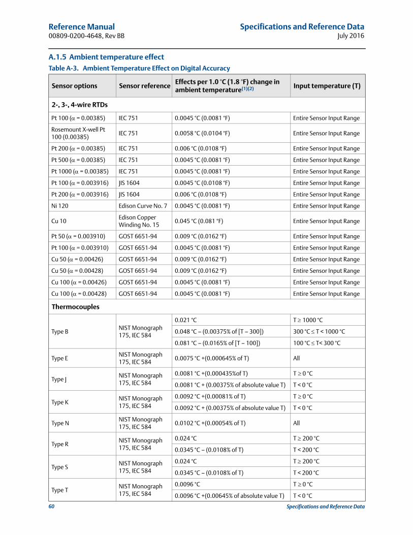
Specifications and Reference DataJuly 2016
Reference Manual 00809-0200-4648, Rev BB
60 Specifications and Reference Data
A.1.5 Ambient temperature effect
Table A-3. Ambient Temperature Effect on Digital Accuracy
Sensor options Sensor referenceEffects per 1.0 °C (1.8 °F) change in ambient temperature(1)(2) Input temperature (T)
2-, 3-, 4-wire RTDs
Pt 100 ( = 0.00385) IEC 751 0.0045 °C (0.0081 °F) Entire Sensor Input Range
Rosemount X-well Pt 100 (0.00385)
IEC 751 0.0058 °C (0.0104 °F) Entire Sensor Input Range
Pt 200 ( = 0.00385) IEC 751 0.006 °C (0.0108 °F) Entire Sensor Input Range
Pt 500 ( = 0.00385) IEC 751 0.0045 °C (0.0081 °F) Entire Sensor Input Range
Pt 1000 ( = 0.00385) IEC 751 0.0045 °C (0.0081 °F) Entire Sensor Input Range
Pt 100 ( = 0.003916) JIS 1604 0.0045 °C (0.0108 °F) Entire Sensor Input Range
Pt 200 ( = 0.003916) JIS 1604 0.006 °C (0.0108 °F) Entire Sensor Input Range
Ni 120 Edison Curve No. 7 0.0045 °C (0.0081 °F) Entire Sensor Input Range
Cu 10Edison Copper Winding No. 15
0.045 °C (0.081 °F) Entire Sensor Input Range
Pt 50 ( = 0.003910) GOST 6651-94 0.009 °C (0.0162 °F) Entire Sensor Input Range
Pt 100 ( = 0.003910) GOST 6651-94 0.0045 °C (0.0081 °F) Entire Sensor Input Range
Cu 50 ( = 0.00426) GOST 6651-94 0.009 °C (0.0162 °F) Entire Sensor Input Range
Cu 50 ( = 0.00428) GOST 6651-94 0.009 °C (0.0162 °F) Entire Sensor Input Range
Cu 100 ( = 0.00426) GOST 6651-94 0.0045 °C (0.0081 °F) Entire Sensor Input Range
Cu 100 ( = 0.00428) GOST 6651-94 0.0045 °C (0.0081 °F) Entire Sensor Input Range
Thermocouples
Type BNIST Monograph 175, IEC 584
0.021 °C T 1000 °C
0.048 °C – (0.00375% of [T – 300]) 300 °C T < 1000 °C
0.081 °C – (0.0165% of [T – 100]) 100 °C T< 300 °C
Type ENIST Monograph 175, IEC 584
0.0075 °C +(0.000645% of T) All
Type JNIST Monograph 175, IEC 584
0.0081 °C +(0.000435%of T) T 0 °C
0.0081 °C + (0.00375% of absolute value T) T < 0 °C
Type KNIST Monograph 175, IEC 584
0.0092 °C +(0.00081% of T) T 0 °C
0.0092 °C + (0.00375% of absolute value T) T < 0 °C
Type NNIST Monograph 175, IEC 584
0.0102 °C +(0.00054% of T) All
Type RNIST Monograph 175, IEC 584
0.024 °C T 200 °C
0.0345 °C – (0.0108% of T) T < 200 °C
Type SNIST Monograph 175, IEC 584
0.024 °C T 200 °C
0.0345 °C – (0.0108% of T) T < 200 °C
Type TNIST Monograph 175, IEC 584
0.0096 °C T 0 °C
0.0096 °C +(0.00645% of absolute value T) T < 0 °C

Specifications and Reference DataJuly 2016
Reference Manual00809-0200-4648, Rev BB
61Specifications and Reference Data
Transmitters can be installed in locations where the ambient temperature is between –40 and 85 °C (–40 and 185 °F). In order to maintain excellent accuracy performance, each transmitter is individually characterized over this ambient temperature range at the factory.
A.1.6 Process temperature effects
Temperature effects example
When using a Pt 100 ( = 0.00385) sensor input at 30 °C ambient temperature:
Digital Temperature Effects: 0.009 °C �(30 - 20) = 0.09 °C
Worst Case Error: Digital + Digital Temperature Effects = 0.45 °C + 0.09 °C = 0.54 °C
Total Probable Error:
Rosemount X-well™ temperature effects example
When using Rosemount X-well Technology at 30 °C ambient temperature and 100 °C process temperature:
Digital Ambient Temperature Effects: 0.0058 °C �(30 - 20) = .058 °C
Process Temperature Effects: 0.01 °C �(100 - 30) = .70 °C
Worst Case Error: Digital Accuracy + Digital Ambient Temperature Effects + Process Temperature Effects = 0.29 °C + 0.058 °C+ 0.70 °C = 1.05 °C
Total Probable Error: = 0.76 °C
DIN Type L DIN 437100.0081 °C + (0.000435% of T) T 0 °C
0.0081 °C +(0.00375% of absolute value T) T < 0 °C
DIN Type U DIN 437100.0096 °C T 0 °C
0.0096 °C +(0.00645% of absolute value T) T < 0 °C
Type W5Re/W26Re ASTM E 988-960.024 °C T 200 °C
0.0345 °C – (0.0108% of T) T < 200 °C
GOST LGOST R. 8.585-2001
0.0105 °C T 0 °C
0.0105 °C + (0.0045% of absolute value T) T < 0 °C
Other input types
Millivolt Input 0.0008 mV Entire Sensor Input Range
2-, 3-, 4-wire Ohm Input 0.0126 Entire Sensor Input Range
1. Change in ambient is with reference to the calibration temperature of the transmitter (20 °C [68 °C]) from factory.
2. Ambient temperature effect specification valid over minimum temperature span of 28 °C.
Table A-4. Ambient and Process Temperature Difference Effect on Digital Accuracy
Sensor option Sensor reference
Effects per 1.0 °C(1.8 °F) difference inAmbient and process temperature(1)
1. Valid under steady state and process ambient conditions.
Input temperature (T)
Rosemount X-well Pt 100(α = 0.00385) IEC 751 ± 0.01 °C (0.018 °F) Entire Sensor Input Range
Table A-3. Ambient Temperature Effect on Digital Accuracy
Sensor options Sensor referenceEffects per 1.0 °C (1.8 °F) change in ambient temperature(1)(2) Input temperature (T)
0.452 0.092+ 0.46=
0.292 0.0582 0.702+ +
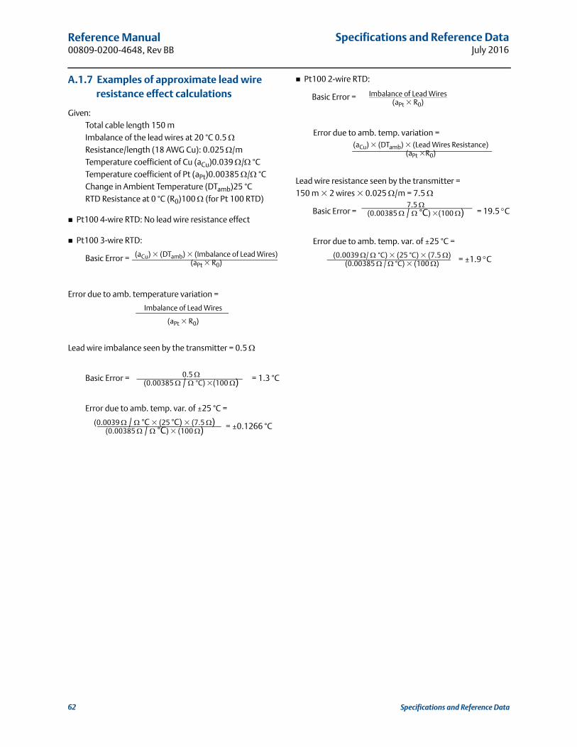
Specifications and Reference DataJuly 2016
Reference Manual 00809-0200-4648, Rev BB
A.1.7 Examples of approximate lead wire resistance effect calculations
Given:Total cable length 150 mImbalance of the lead wires at 20 °C 0.5 Resistance/length (18 AWG Cu): 0.025 /mTemperature coefficient of Cu (aCu)0.039 / °CTemperature coefficient of Pt (aPt)0.00385 / °CChange in Ambient Temperature (DTamb)25 °CRTD Resistance at 0 °C (R0)100 (for Pt 100 RTD)
Pt100 4-wire RTD: No lead wire resistance effect
Pt100 3-wire RTD:
Basic Error =
Error due to amb. temperature variation =
Lead wire imbalance seen by the transmitter = 0.5
Basic Error = = 1.3 °C
Error due to amb. temp. var. of ±25 °C =
= ±0.1266 °C
Pt100 2-wire RTD:
Basic Error =
Error due to amb. temp. variation =
Lead wire resistance seen by the transmitter = 150 m � 2 wires � 0.025 /m = 7.5
Basic Error = = 19.5 C
Error due to amb. temp. var. of ±25 °C =
= ±1.9 C
Imbalance of Lead Wires(aPt � R0)
0.5 (0.00385 / °C) �(100 )
(0.0039 / °C) � (25 °C) � (7.5 )(0.00385 / °C) � (100 )
(aCu) � (DTamb) � (Lead Wires Resistance)(aPt �R0)
7.5 (0.00385 / °C) �(100 )
(0.0039 / °C � (25 °C) � (7.5 )(0.00385 / °C) � (100 )
(aCu) � (DTamb) � (Imbalance of Lead Wires)(aPt � R0)
Imbalance of Lead Wires
(aPt � R0)
62 Specifications and Reference Data
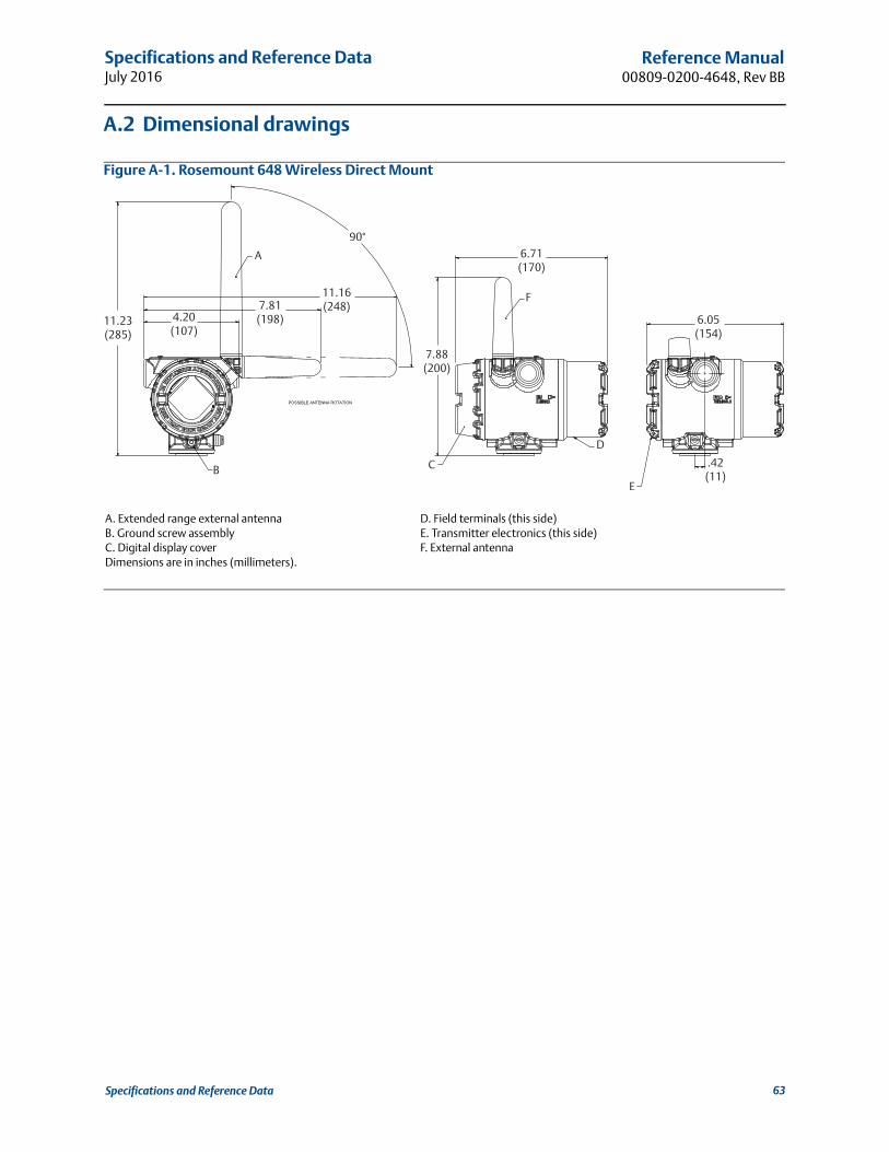
Specifications and Reference DataJuly 2016
Reference Manual00809-0200-4648, Rev BB
A.2 Dimensional drawings
Figure A-1. Rosemount 648 Wireless Direct Mount
A. Extended range external antennaB. Ground screw assemblyC. Digital display coverDimensions are in inches (millimeters).
D. Field terminals (this side)E. Transmitter electronics (this side)F. External antenna
A
B C
D
E
F
11.23(285)
4.20(107)
7.81(198)
11.16(248)
90°
7.88(200)
6.71(170)
6.05(154)
.42(11)
63Specifications and Reference Data
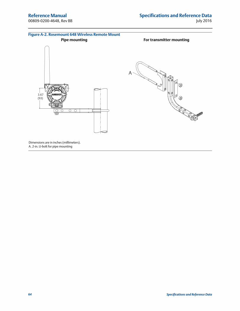
Specifications and Reference DataJuly 2016
Reference Manual 00809-0200-4648, Rev BB
64 Specifications and Reference Data
Figure A-2. Rosemount 648 Wireless Remote MountPipe mounting For transmitter mounting
Dimensions are in inches (millimeters).A. 2-in. U-bolt for pipe mounting
3.67(93)
A

Specifications and Reference DataJuly 2016
Reference Manual00809-0200-4648, Rev BB
65Specifications and Reference Data
Figure A-3. Rosemount 648 Wireless with Option Code PT
Dimensions are in inches (millimeters).
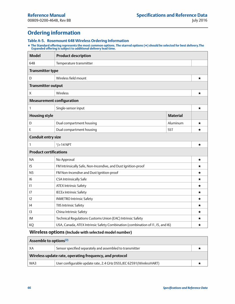
Specifications and Reference DataJuly 2016
Reference Manual 00809-0200-4648, Rev BB
Ordering informationTable A-5. Rosemount 648 Wireless Ordering Information★ The Standard offering represents the most common options. The starred options (★) should be selected for best delivery.The
Expanded offering is subject to additional delivery lead time.
Model Product description
648 Temperature transmitter
Transmitter type
D Wireless field mount ★
Transmitter output
X Wireless ★
Measurement configuration
1 Single-sensor input ★
Housing style Material
D Dual compartment housing Aluminum ★
E Dual compartment housing SST ★
Conduit entry size
1 1/2-14 NPT ★
Product certifications
NA No Approval ★
I5 FM Intrinsically Safe, Non-Incendive, and Dust Ignition-proof ★
N5 FM Non-Incendive and Dust Ignition-proof ★
I6 CSA Intrinsically Safe ★
I1 ATEX Intrinsic Safety ★
I7 IECEx Intrinsic Safety ★
I2 INMETRO Intrinsic Safety ★
I4 TIIS Intrinsic Safety ★
I3 China Intrinsic Safety ★
IM Technical Regulations Customs Union (EAC) Intrinsic Safety ★
KQ USA, Canada, ATEX Intrinsic Safety Combination (combination of I1, I5, and I6) ★
Wireless options (Include with selected model number)
Assemble to options(2)
XA Sensor specified separately and assembled to transmitter ★
Wireless update rate, operating frequency, and protocol
WA3 User configurable update rate, 2.4 GHz DSSS,IEC 62591(WirelessHART) ★
66 Specifications and Reference Data
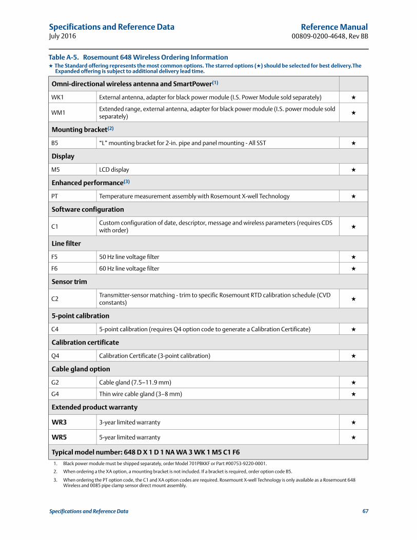
Specifications and Reference DataJuly 2016
Reference Manual00809-0200-4648, Rev BB
Omni-directional wireless antenna and SmartPower(1)
WK1 External antenna, adapter for black power module (I.S. Power Module sold separately) ★
WM1Extended range, external antenna, adapter for black power module (I.S. power module sold separately)
★
Mounting bracket(2)
B5 “L” mounting bracket for 2-in. pipe and panel mounting - All SST ★
Display
M5 LCD display ★
Enhanced performance(3)
PT Temperature measurement assembly with Rosemount X-well Technology ★
Software configuration
C1Custom configuration of date, descriptor, message and wireless parameters (requires CDS with order)
★
Line filter
F5 50 Hz line voltage filter ★
F6 60 Hz line voltage filter ★
Sensor trim
C2Transmitter-sensor matching - trim to specific Rosemount RTD calibration schedule (CVD constants)
★
5-point calibration
C4 5-point calibration (requires Q4 option code to generate a Calibration Certificate) ★
Calibration certificate
Q4 Calibration Certificate (3-point calibration) ★
Cable gland option
G2 Cable gland (7.5–11.9 mm) ★
G4 Thin wire cable gland (3–8 mm) ★
Extended product warranty
WR3 3-year limited warranty ★
WR5 5-year limited warranty ★
Typical model number: 648 D X 1 D 1 NA WA 3 WK 1 M5 C1 F6
1. Black power module must be shipped separately, order Model 701PBKKF or Part #00753-9220-0001.
2. When ordering a the XA option, a mounting bracket is not included. If a bracket is required, order option code B5.
3. When ordering the PT option code, the C1 and XA option codes are required. Rosemount X-well Technology is only available as a Rosemount 648 Wireless and 0085 pipe clamp sensor direct mount assembly.
Table A-5. Rosemount 648 Wireless Ordering Information★ The Standard offering represents the most common options. The starred options (★) should be selected for best delivery.The
Expanded offering is subject to additional delivery lead time.
67Specifications and Reference Data

Specifications and Reference DataJuly 2016
Reference Manual 00809-0200-4648, Rev BB
68 Specifications and Reference Data
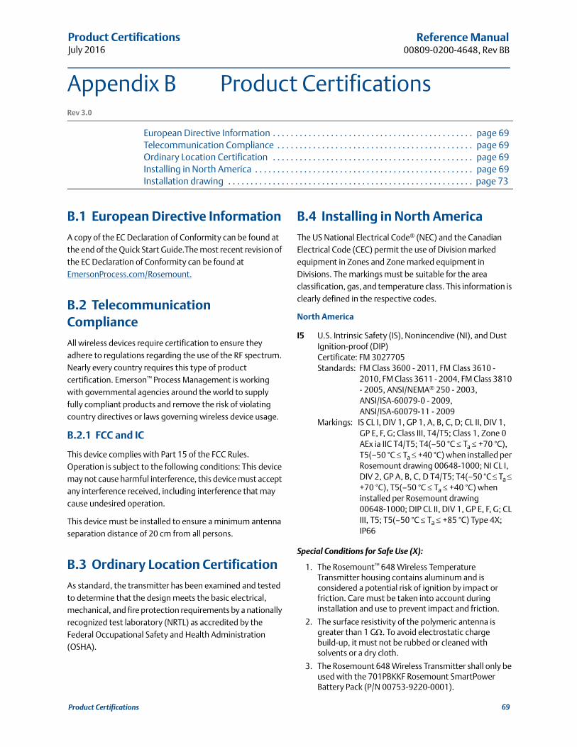
Product CertificationsJuly 2016
Reference Manual00809-0200-4648, Rev BB
Appendix B Product CertificationsRev 3.0
European Directive Information . . . . . . . . . . . . . . . . . . . . . . . . . . . . . . . . . . . . . . . . . . . . . page 69Telecommunication Compliance . . . . . . . . . . . . . . . . . . . . . . . . . . . . . . . . . . . . . . . . . . . . page 69Ordinary Location Certification . . . . . . . . . . . . . . . . . . . . . . . . . . . . . . . . . . . . . . . . . . . . . page 69Installing in North America . . . . . . . . . . . . . . . . . . . . . . . . . . . . . . . . . . . . . . . . . . . . . . . . . page 69Installation drawing . . . . . . . . . . . . . . . . . . . . . . . . . . . . . . . . . . . . . . . . . . . . . . . . . . . . . . . page 73
B.1 European Directive Information
A copy of the EC Declaration of Conformity can be found at the end of the Quick Start Guide.The most recent revision of the EC Declaration of Conformity can be found at EmersonProcess.com/Rosemount.
B.2 Telecommunication Compliance
All wireless devices require certification to ensure they adhere to regulations regarding the use of the RF spectrum. Nearly every country requires this type of product certification. Emerson™ Process Management is working with governmental agencies around the world to supply fully compliant products and remove the risk of violating country directives or laws governing wireless device usage.
B.2.1 FCC and IC
This device complies with Part 15 of the FCC Rules. Operation is subject to the following conditions: This device may not cause harmful interference, this device must accept any interference received, including interference that may cause undesired operation.
This device must be installed to ensure a minimum antenna separation distance of 20 cm from all persons.
B.3 Ordinary Location Certification
As standard, the transmitter has been examined and tested to determine that the design meets the basic electrical, mechanical, and fire protection requirements by a nationally recognized test laboratory (NRTL) as accredited by the Federal Occupational Safety and Health Administration (OSHA).
B.4 Installing in North America
The US National Electrical Code® (NEC) and the Canadian Electrical Code (CEC) permit the use of Division marked equipment in Zones and Zone marked equipment in Divisions. The markings must be suitable for the area classification, gas, and temperature class. This information is clearly defined in the respective codes.
North America
I5 U.S. Intrinsic Safety (IS), Nonincendive (NI), and Dust Ignition-proof (DIP)Certificate: FM 3027705Standards: FM Class 3600 - 2011, FM Class 3610 -
2010, FM Class 3611 - 2004, FM Class 3810 - 2005, ANSI/NEMA® 250 - 2003, ANSI/ISA-60079-0 - 2009, ANSI/ISA-60079-11 - 2009
Markings: IS CL I, DIV 1, GP 1, A, B, C, D; CL II, DIV 1, GP E, F, G; Class III, T4/T5; Class 1, Zone 0 AEx ia IIC T4/T5; T4(–50 °C Ta +70 °C), T5(–50 °C Ta +40 °C) when installed per Rosemount drawing 00648-1000; NI CL I, DIV 2, GP A, B, C, D T4/T5; T4(–50 °C Ta +70 °C), T5(–50 °C Ta +40 °C) when installed per Rosemount drawing 00648-1000; DIP CL II, DIV 1, GP E, F, G; CL III, T5; T5(–50 °C Ta +85 °C) Type 4X; IP66
Special Conditions for Safe Use (X):
1. The Rosemount™ 648 Wireless Temperature Transmitter housing contains aluminum and is considered a potential risk of ignition by impact or friction. Care must be taken into account during installation and use to prevent impact and friction.
2. The surface resistivity of the polymeric antenna is greater than 1 G. To avoid electrostatic charge build-up, it must not be rubbed or cleaned with solvents or a dry cloth.
3. The Rosemount 648 Wireless Transmitter shall only be used with the 701PBKKF Rosemount SmartPower Battery Pack (P/N 00753-9220-0001).
69Product Certifications

Product CertificationsJuly 2016
Reference Manual 00809-0200-4648, Rev BB
N5 U.S. Nonincendive (NI) and Dust Ignition-proof (DIP)Certificate: FM 3027705Standards: FM Class 3600 - 2011, FM Class 3611 -
2004, FM Class 3810 - 2005, ANSI/NEMA 250 - 2003
Markings: NI CL I, DIV 2, GP A, B, C, D T4/T5; T4(–50 °C Ta +70 °C), T5(–50 °C Ta +40 °C)DIP CL II, DIV 1, GP E, F, G; CL III, T5;T5(–50 °C Ta +85 °C)Type 4X; IP66/67
Special Condition for Safe Use (X):
1. For use only with the Model 701PBKKF or Rosemount P/N 753-9220-XXXX SmartPower Battery Module.
Canada
I6 Canada Intrinsically SafeCertificate: CSA 1143113Standards: CAN/CSA C22.2 No. 0-10,
CAN/CSA C22.2 No. 94-M91, CSA Std C22.2 No. 142-M1987,CSA Std C22.2 No. 157-92, CSA Std C22.2 No. 60529:05
Markings: Intrinsically Safe Class I, Division 1, Groups A, B, C and D T3C; Class 1, Zone 0, IIC, T3C; when connected per Rosemount drawing 00648-1020; Type 4X
Europe
I1 ATEX Intrinsic SafetyCertificate: Baseefa07ATEX0011X;Standards: EN 60079-0: 2012 + A11:2013, EN
60079-11: 2012Markings: II 1 G Ex ia IIC T4 Ga,
T4(–60 °C Ta +70 °C) II 1 GEx ia IIC T5 Ga,
T5(–60 °C Ta +40 °C)
For use with Rosemount SmartPower power module part number 753-9220-0001, or for use with Emerson SmartPower option 701PBKKF.
Special Condition for Safe Use (X):
1. The surface resistivity of the antenna is greater than one gigaohm. To avoid electrostatic charge build-up, it must not be rubbed or cleaned with solvents or a dry cloth.
2. The power module may be replaced in a hazardous area. The power module has a surface resistivity greater than 1 G and must be properly installed in the wireless device enclosure. Care must be taken during transportation to and from the point of installation to prevent electrostatic charge build-up.
NM ATEX Intrinsic Safety for MiningCertificate: Baseefa07ATEX0011X;Standards: EN 60079-0: 2012 + A11:2013, EN
60079-11: 2012Markings: I M 1 Ex ia I Ma (-60 °C Ta +70 °C)
Sensor terminal parameters
UO = 6.6 V
IO = 26.2 mA
PO = 42.6 mW
CO = 23.8 μF
LO = 50 mH
Sensor terminal parameters
UO = 6.6 V
IO = 26.2 mA
PO = 42.6 mW
Ca = 23.8 μF
La = 50 mH
Sensor terminal parameters
UO = 6.6 V
IO = 26.2 mA
PO = 42.6 mW
CO = 11 μF
LO = 25 mH
Sensor terminal parameters
UO = 6.6 V
IO = 26.2 mA
PO = 42.6 mW
CO = 11 μF
LO = 25 mH
70 Product Certifications
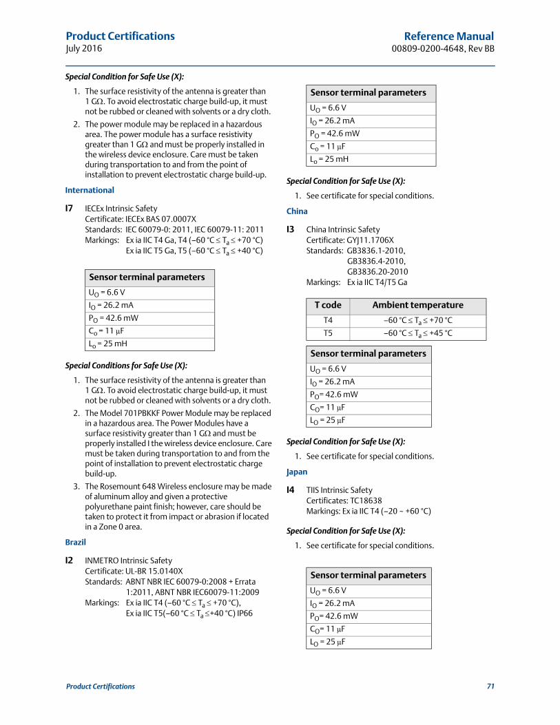
Product CertificationsJuly 2016
Reference Manual00809-0200-4648, Rev BB
Special Condition for Safe Use (X):
1. The surface resistivity of the antenna is greater than1 G. To avoid electrostatic charge build-up, it must not be rubbed or cleaned with solvents or a dry cloth.
2. The power module may be replaced in a hazardous area. The power module has a surface resistivity greater than 1 G and must be properly installed in the wireless device enclosure. Care must be taken during transportation to and from the point of installation to prevent electrostatic charge build-up.
International
I7 IECEx Intrinsic SafetyCertificate: IECEx BAS 07.0007XStandards: IEC 60079-0: 2011, IEC 60079-11: 2011Markings: Ex ia IIC T4 Ga, T4 (–60 °C Ta +70 °C)
Ex ia IIC T5 Ga, T5 (–60 °C Ta +40 °C)
Special Conditions for Safe Use (X):
1. The surface resistivity of the antenna is greater than 1 G. To avoid electrostatic charge build-up, it must not be rubbed or cleaned with solvents or a dry cloth.
2. The Model 701PBKKF Power Module may be replaced in a hazardous area. The Power Modules have a surface resistivity greater than 1 G and must be properly installed I the wireless device enclosure. Care must be taken during transportation to and from the point of installation to prevent electrostatic charge build-up.
3. The Rosemount 648 Wireless enclosure may be made of aluminum alloy and given a protective polyurethane paint finish; however, care should be taken to protect it from impact or abrasion if located in a Zone 0 area.
Brazil
I2 INMETRO Intrinsic SafetyCertificate: UL-BR 15.0140XStandards: ABNT NBR IEC 60079-0:2008 + Errata
1:2011, ABNT NBR IEC60079-11:2009Markings: Ex ia IIC T4 (–60 °C Ta +70 °C),
Ex ia IIC T5(–60 °C Ta +40 °C) IP66
Special Condition for Safe Use (X):
1. See certificate for special conditions.
China
I3 China Intrinsic SafetyCertificate: GYJ11.1706XStandards: GB3836.1-2010,
GB3836.4-2010, GB3836.20-2010
Markings: Ex ia IIC T4/T5 Ga
Special Condition for Safe Use (X):
1. See certificate for special conditions.
Japan
I4 TIIS Intrinsic SafetyCertificates: TC18638Markings: Ex ia IIC T4 (–20 ~ +60 °C)
Special Condition for Safe Use (X):
1. See certificate for special conditions.
Sensor terminal parameters
UO = 6.6 V
IO = 26.2 mA
PO = 42.6 mW
Co = 11 μF
Lo = 25 mH
Sensor terminal parameters
UO = 6.6 V
IO = 26.2 mA
PO = 42.6 mW
Co = 11 μF
Lo = 25 mH
T code Ambient temperature
T4 –60 °C Ta +70 °C
T5 –60 °C Ta +45 °C
Sensor terminal parameters
UO = 6.6 V
IO = 26.2 mA
PO= 42.6 mW
CO= 11 μF
LO = 25 μF
Sensor terminal parameters
UO = 6.6 V
IO = 26.2 mA
PO= 42.6 mW
CO= 11 μF
LO = 25 μF
71Product Certifications
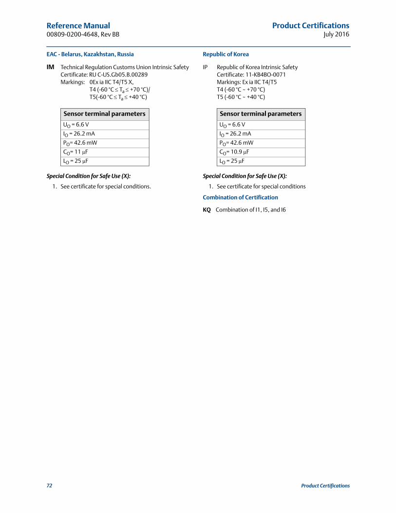
Product CertificationsJuly 2016
Reference Manual 00809-0200-4648, Rev BB
72 Product Certifications
EAC - Belarus, Kazakhstan, Russia
IM Technical Regulation Customs Union Intrinsic SafetyCertificate: RU C-US.Gb05.B.00289Markings: 0Ex ia IIC T4/T5 X,
T4 (-60 °C Ta +70 °C)/T5(-60 °C Ta +40 °C)
Special Condition for Safe Use (X):
1. See certificate for special conditions.
Republic of Korea
IP Republic of Korea Intrinsic SafetyCertificate: 11-KB4BO-0071Markings: Ex ia IIC T4/T5T4 (-60 °C ~ +70 °C)T5 (-60 °C ~ +40 °C)
Special Condition for Safe Use (X):
1. See certificate for special conditions
Combination of Certification
KQ Combination of I1, I5, and I6
Sensor terminal parameters
UO = 6.6 V
IO = 26.2 mA
PO= 42.6 mW
CO= 11 μF
LO = 25 μF
Sensor terminal parameters
UO = 6.6 V
IO = 26.2 mA
PO= 42.6 mW
CO= 10.9 μF
LO = 25 μF

Product CertificationsJuly 2016
Reference Manual00809-0200-4648, Rev BB
B.5 Installation drawing
Figure B-1. Rosemount 648 Wireless Intrinsically Safe Installation Drawing
73Product Certifications
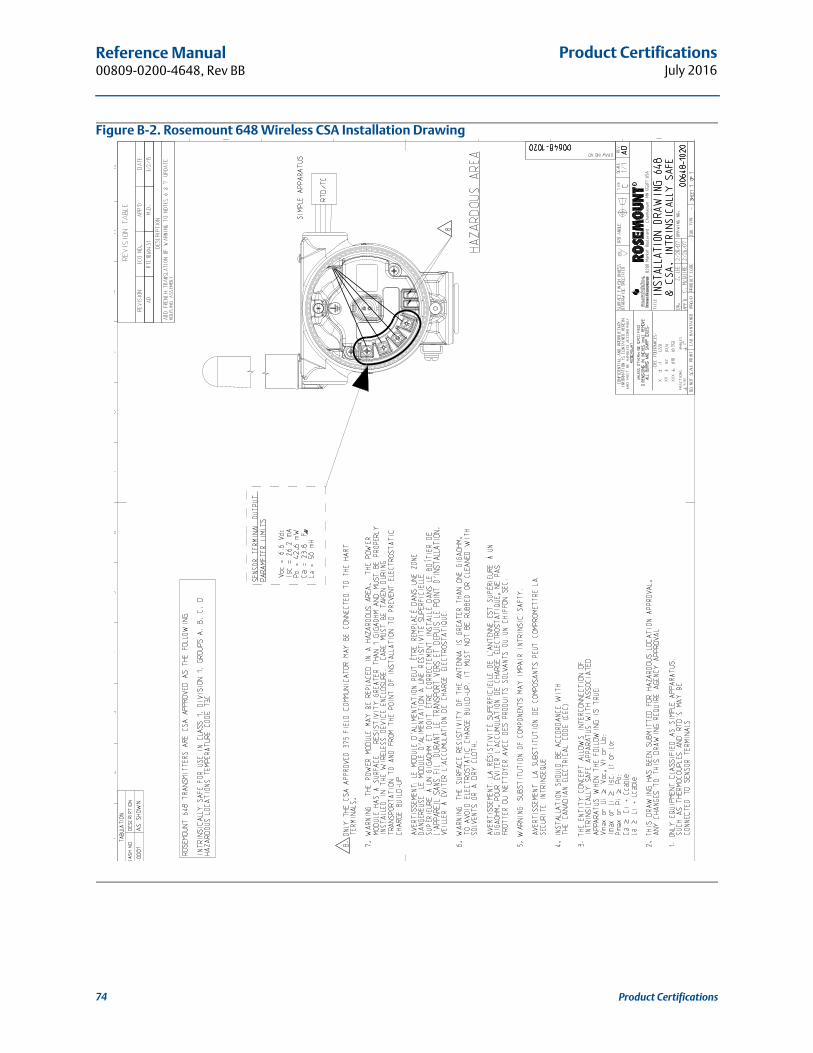
Product CertificationsJuly 2016
Reference Manual 00809-0200-4648, Rev BB
Figure B-2. Rosemount 648 Wireless CSA Installation Drawing
74 Product Certifications

Mapping for Non-DD Based Integration with Host SystemsJuly 2016
Reference Manual00809-0200-4648, Rev BB
Appendix C Mapping for Non-DD Based Integration with Host Systems
Alert message mapping . . . . . . . . . . . . . . . . . . . . . . . . . . . . . . . . . . . . . . . . . . . . . . . . . . . page 75Mapping of device variables index numbers . . . . . . . . . . . . . . . . . . . . . . . . . . . . . . . . . . page 77
C.1 Alert message mapping
This outlines the most important alerts in the HART® command 48 Additional Status Field for the Rosemount™ 648 Wireless Temperature Transmitter. The information in this section can be used by DeltaV™ for alert monitoring, and in the Rosemount 1420 Smart Wireless Gateway for Additional Status mapping in Modbus®, OPC, etc.
A complete list of Additional Status bits is available in the Rosemount 1420 Reference Manual.
Table C-1 to Table C-3 shows a list of the most important alert messages that may display in the AMS™ Wireless Configurator and Field Communicator together with the location of the Alert in the HART command 48 Additional Status field. For recommended actions refer to Table 6-1. on page 53.
To view Active Alerts, from the Home screen, go to Service Tools>Active Alerts.
Table C-1. Failure Alerts (F:)
Message Additional status(1)
1. Location of the Alert in the HART command 48 Status field.
Description
Electronics Failure
Byte 0 :: Bit 0Byte 0 :: Bit 1Byte 0 :: Bit 3Byte 0 :: Bit 6Byte 0 :: Bit 7Byte 8 :: Bit 1Byte 8 :: Bit 2Byte 8 :: Bit 6
An electronics error that could impact the device measurement reading has occurred
Terminal Block FailureByte 3 :: Bit 2Byte 3 :: Bit 3Byte 3 :: Bit 6
A critical failure has occurred in the transmitter's terminal block
Sensor Failure Byte 3 :: Bit 7 The device has detected an open, short, or too much resistance for this sensor
Radio FailureByte 1 :: Bit 1Byte 1 :: Bit 7
The wireless radio has detected a failure or stopped communicating
Supply Voltage FailureByte 1 :: Bit 4Byte 5 :: Bit 2
The supply voltage is too low for the device to broadcast
75Mapping for Non-DD Based Integration with Host Systems

Mapping for Non-DD Based Integration with Host SystemsJuly 2016
Reference Manual 00809-0200-4648, Rev BB
Table C-2. Maintenance Alerts (M:)
Message Additional status(1) Description
Electronics WarningByte 0 :: Bit 4Byte 0 :: Bit 5
The device has detected an electronics error that does not currently impact the device measurement reading
Sensor has Exceeded LimitsByte 3 :: Bit 4Byte 3 :: Bit 5
The sensor has exceeded the maximum measurement range
Electronics Temperature has Exceeded Limits
Byte 1 :: Bit 2Byte 1 :: Bit 3Byte 8 :: Bit 5
The terminal temperature has exceeded the transmitter's maximum range
Electronics Temperature has Exceeded Limits
Byte 3 :: Bit 0Byte 3 :: Bit 1
The electronics temperature has exceeded the transmitter’s maximum range.
Supply Voltage LowByte 1 :: Bit 6Byte 8 :: Bit 4
The supply voltage is low and may soon affect broadcast updates
1. Location of the Alert in the HART command 48 Status field.
Table C-3. Advisory Alerts (A:)
Message Additional status(1)
1. Location of the Alert in the HART command 48 Status field.
Description
Database Memory Warning Byte 0 :: Bit 2The device has failed to write to the database memory / Any data written during this time may have been lost
Invalid Configuration Byte 2 :: Bit 6 The device has detected a configuration error based on a change to the device
HI HI Alarm Byte 5 :: Bit 4 The primary variable has surpassed the user defined limit
HI Alarm Byte 5 :: Bit 5 The primary variable has surpassed the user defined limit
LO Alarm Byte 5 :: Bit 6 The primary variable has surpassed the user defined limit
LO LO Alarm Byte 5 :: Bit 7 The primary variable has surpassed the user defined limit
Button Stuck Byte 1 :: Bit 5 A button on the Electronics Board is detected as stuck in the active position
Simulation Active Byte 8 :: Bit 0 The device is in simulation mode and may not be reporting actual information
76 Mapping for Non-DD Based Integration with Host Systems

Mapping for Non-DD Based Integration with Host SystemsJuly 2016
Reference Manual00809-0200-4648, Rev BB
C.2 Mapping of device variables index numbers
To integrate a device into the host system, it may be necessary to know what each device variable represents, and what index number it has been assigned to. The variable index number is an arbitrary number used to uniquely identify each variable supported in the field device.
Table C-4 to Table C-5 displays the device variable and variable mapping indexes for the Rosemount 648 Wireless.
Table C-4. Device Variable Index
Device variable index Description
0 Supply voltage
1 Electronics temperature
2 Process temperature
3 Terminal temperature
244 Percent of range
Table C-5. Variable Mapping
Process variables Mapped variable index
PV 2 - Process temperature
SV 3 - Terminal temperature
TV 1 - Electronics temperature
QV 0 - Supply voltage
77Mapping for Non-DD Based Integration with Host Systems

Mapping for Non-DD Based Integration with Host SystemsJuly 2016
Reference Manual 00809-0200-4648, Rev BB
78 Mapping for Non-DD Based Integration with Host Systems


Reference Manual00809-0200-4648, Rev BB
July 2016
Global Headquarters
Emerson Process Management 6021 Innovation Blvd.Shakopee, MN 55379, USA+1 800 999 9307 or +1 952 906 8888+1 952 949 7001 [email protected]
North America Regional OfficeEmerson Process Management 8200 Market Blvd.Chanhassen, MN 55317, USA
+1 800 999 9307 or +1 952 906 8888+1 952 949 7001 [email protected]
Latin America Regional OfficeEmerson Process Management 1300 Concord Terrace, Suite 400Sunrise, FL 33323, USA
+1 954 846 5030+1 954 846 [email protected]
Europe Regional OfficeEmerson Process Management Europe GmbHNeuhofstrasse 19a P.O. Box 1046CH 6340 BaarSwitzerland
+41 (0) 41 768 6111+41 (0) 41 768 6300 [email protected]
Asia Pacific Regional OfficeEmerson Process Management Asia Pacific Pte Ltd
Linkedin.com/company/Emerson-Process-Management
Twitter.com/Rosemount_News
Facebook.com/Rosemount
Youtube.com/user/RosemountMeasurement
1 Pandan CrescentSingapore 128461+65 6777 8211+65 6777 0947 [email protected]
Middle East and Africa Regional OfficeEmerson Process Management Emerson FZE P.O. Box 17033Jebel Ali Free Zone - South 2Dubai, United Arab Emirates
+971 4 8118100+971 4 8865465 [email protected]
Google.com/+RosemountMeasurement
Standard Terms and Conditions of Sale can be found at:www.Emerson.com/en-us/pages/Terms-of-Use.aspxThe Emerson logo is a trademark and service mark of Emerson Electric Co.SmartPower, DeltaV, AMS, Rosemount X-well, Rosemount. and the Rosemount logotype are trademarks of Emerson Process Management.Swagelok is a registered trademark of Swagelok Company.HART and WIrelessHART are registered trademarks of FieldComm Group.Modbus is a registered trademark of Modicon, Inc.National Electrical Code is a registered trademark of National Fire Protection Association, Inc.NEMA is a registered trademark and service mark of the National Electrical Manufacturers Association.All other marks are the property of their respective owners.© 2016 Emerson Process Management. All rights reserved.
Related Documents