4/21/17 1 Copyright © 2018, 2014, 2012 Pearson Education, Inc. All Rights Reserved Manual Drivetrains and Axles 8 th Edition Chapter 3 Introduction to Drivetrains Copyright © 2018, 2014, 2012 Pearson Education, Inc. All Rights Reserved Learning Objectives (1 of 2) 1.1 Define torque, and explain the relationship between torque and horsepower. 1.2 Describe the various gear types and their effect on speed, torque, and direction of rotation. 1.3 Explain gear ratios and their effect on vehicle operation. 1.4 Discuss the types of manual transmissions and transaxles that are currently in use. Copyright © 2018, 2014, 2012 Pearson Education, Inc. All Rights Reserved Learning Objectives (2 of 2) 1.5 Discuss automatic transmissions and the planetary gear sets used for automatic transmissions. 1.6 Compare rear-wheel drive, front-wheel drive, four-wheel drive, and all-wheel drive. 1.7 Explain the characteristics of driveshafts and drive axle assemblies.

Welcome message from author
This document is posted to help you gain knowledge. Please leave a comment to let me know what you think about it! Share it to your friends and learn new things together.
Transcript
4/21/17
1
Copyright © 2018, 2014, 2012 Pearson Education, Inc. All Rights Reserved
Manual Drivetrains and Axles8th Edition
Chapter 3Introduction to
Drivetrains
Copyright © 2018, 2014, 2012 Pearson Education, Inc. All Rights Reserved
Learning Objectives (1 of 2)
1.1 Define torque, and explain the relationship
between torque and horsepower.
1.2 Describe the various gear types and their effect
on speed, torque, and direction of rotation.
1.3 Explain gear ratios and their effect on vehicle
operation.
1.4 Discuss the types of manual transmissions and
transaxles that are currently in use.
Copyright © 2018, 2014, 2012 Pearson Education, Inc. All Rights Reserved
Learning Objectives (2 of 2)
1.5 Discuss automatic transmissions and the
planetary gear sets used for automatic
transmissions.
1.6 Compare rear-wheel drive, front-wheel drive,
four-wheel drive, and all-wheel drive.
1.7 Explain the characteristics of driveshafts and
drive axle assemblies.
4/21/17
2
Copyright © 2018, 2014, 2012 Pearson Education, Inc. All Rights Reserved
Drivetrains
• The drivetrain, also called a powertrain, serves the
following functions:
– It allows the driver to control the power flow.
– It multiplies the engine torque.
– It controls the engine speed.
Copyright © 2018, 2014, 2012 Pearson Education, Inc. All Rights Reserved
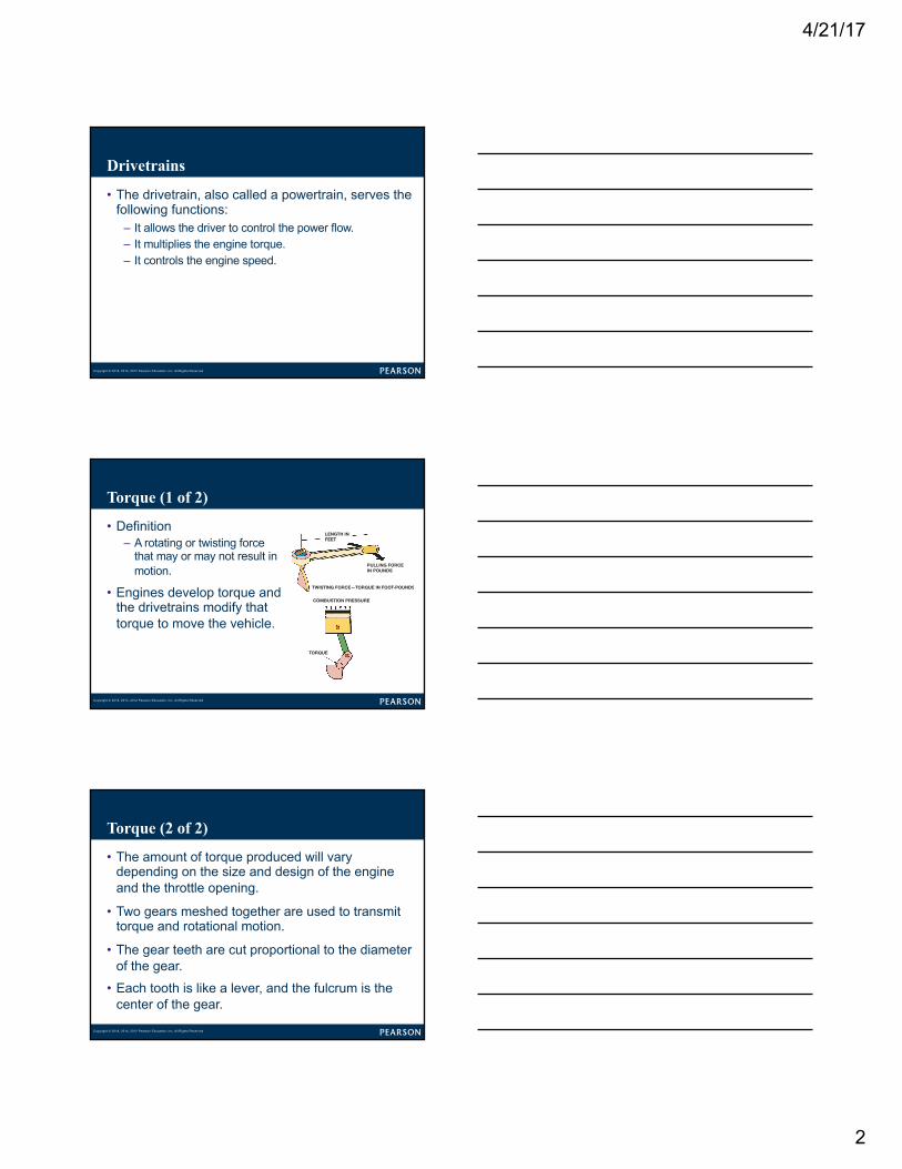
Torque (1 of 2)
• Definition
– A rotating or twisting force
that may or may not result in
motion.
• Engines develop torque and
the drivetrains modify that
torque to move the vehicle.
2 CHAPTER 1
UNITS OF TORQUE Engine torque is developed when combustion pressure pushes a piston downward to rotate the crankshaft. ● SEE FIGURE 1–1.
The amount of torque produced will vary depending on the size and design of the engine and the throttle opening. Torque is measured in pounds-feet (lb-ft) or Newton-meters (N-m). One Newton-meter of torque is equal to 0.737 lb-ft. A factor that greatly affects drivetrain design is that very little or no torque is developed at engine speeds below 1000 RPM (revolutions per minute). An engine begins producing usable torque at about 1200 RPM and peak torque at about 2500 to 4000 RPM, with an upper usable speed limit of 5000 to 7000 RPM. The gear ratios in the transmission and drive axle are used to match the engine speed and torque output to the ve-hicle speed and torque requirements. ● SEE FIGURE 1–2.
DRIVE VS. DRIVEN GEARS The drive gear is the gear that is the source of the engine torque and rotation. The driven gear is the gear that is driven or rotated by the drive gear. Two gears meshed together are used to transmit torque and rotational motion. The driven gear can then rotate yet another gear. In this case, the second gear becomes the drive gear and the third gear is the driven gear.
TORQUE MULTIPLICATION The gear teeth are cut pro-portional to the diameter of the gear. If one of two mating gears was twice as large as the other, it would have twice as many teeth. For example, if the smaller gear has 10 teeth, a gear twice as large will have 20 teeth. If the teeth of these gears are inter-meshed, 10 teeth of each gear will come into contact when the smaller gear rotates one revolution. This will require one revolu-tion of the small gear and one-half revolution of the larger gear. It will take two revolutions of the small gear to produce one revolution of the larger gear. This is a gear ratio of 2:1, assuming that the small gear is the drive gear. To determine a gear ratio, divide the driven gear by the driving gear. ● SEE FIGURE 1–3.
DRIVETRAINS
PURPOSE AND FUNCTION The purpose of a vehicle drivetrain is to transfer power from the engine to the drive wheels. The drivetrain, also called a powertrain, serves the following functions:
■ It allows the driver to control the power flow.
■ It multiplies the engine torque.
■ It controls the engine speed.
TORQUE
DEFINITION Torque is a rotating or twisting force that may or may not result in motion. A vehicle moves because of the torque the drive axle exerts on the wheels and tires to make them rotate. Being a form of mechanical energy, torque cannot be created or destroyed—it is converted from one form of energy to another form of energy.
Is It Lb-Ft or Ft-Lb of Torque?
The unit for torque is expressed as a force times the distance (leverage) from the object. Therefore, the official unit for torque is lb-ft (pound-feet) or Newton-meters (a force times a distance). However, it is com-monly expressed in ft-lb and most torque wrenches are labeled with this unit.
? FREQUENTLY ASKED QUESTION
LENGTH INFEET
PULLING FORCEIN POUNDS
TWISTING FORCE—TORQUE IN FOOT-POUNDS
COMBUSTION PRESSURE
TORQUE
FIGURE 1–1 Torque, a twisting force, is produced when you pull on a wrench. An engine produces torque at the crankshaft as combustion pressure pushes the piston downward.
M01_HALD6797_07_SE_C01.indd 2 09/11/16 12:02 pm
Copyright © 2018, 2014, 2012 Pearson Education, Inc. All Rights Reserved
Torque (2 of 2)
• The amount of torque produced will vary
depending on the size and design of the engine
and the throttle opening.
• Two gears meshed together are used to transmit
torque and rotational motion.
• The gear teeth are cut proportional to the diameter
of the gear.
• Each tooth is like a lever, and the fulcrum is the
center of the gear.
4/21/17
3
Copyright © 2018, 2014, 2012 Pearson Education, Inc. All Rights Reserved
Horsepower
• Power equals work divided by time.
• Torque and horsepower:
– Horsepower = Torque × rpm/5,252
4 CHAPTER 1
is expressed as 550 foot-pounds (ft-lb) per second or 33,000 foot-pounds per minute. ● SEE FIGURE 1–5.
HORSEPOWER AND TORQUE RELATIONSHIP To determine horsepower, a dynamometer is used to measure the amount of torque an engine can produce at various points through its operating range. The formula used to convert torque at a certain revolution per minute (RPM) into a horsepower reading is
Horsepower = Torque × RPM/5,252
NOTE: To determine how the constant “5,252” was de-rived, perform an Internet search to see an explanation.
The various readings are then plotted into a curve. A typi-cal horsepower and torque curve shows us that an engine does not produce very much torque at low RPM. The most usable torque is produced in the mid-RPM range. Torque decreases with an increase in horsepower at a higher RPM.
The torque from an engine can be increased or decreased through the use of gears, belts, and chains. Gears, belts, or chains cannot increase horsepower; they can only modify
its effect. A gear set can increase torque, but it will decrease speed by the same amount.
10 FEET
100 LBS
FIGURE 1–4 Work is calculated by multiplying force times distance. If you push 100 pounds 10 feet, you have done 1,000 foot-pounds of work.
165 FEET(50 M)PERMINUTE
200POUNDS(91 KG)
165 FEET(50 M)
FIGURE 1–5 One horsepower is equal to 33,000 foot-pounds (200 lbs × 165 ft) of work per minute.
How to Explain the Difference between Horsepower and Torque
As Carroll Shelby, the well-known racer and business owner, said, “Horsepower sells cars, but torque wins races.” Torque determines how fast the vehicle will accelerate, and horsepower determines how fast the vehicle will go.
TECH TIP
PITCH DIAMETER
PITCH DIAMETER OFDRIVING GEAR
PITCH DIAMETER OFDRIVING GEAR
POINT A POINT BPOINT C
FIGURE 1–6 The pitch diameter is the effective diameter of the gear. Note how the contact points slide on the gear teeth as they move in and out of contact.
GEARS
TERMINOLOGY The effective diameter of a gear is the pitch diameter (or pitch line). ● SEE FIGURE 1–6.
The pitch diameter is the diameter of the gear at the point where the teeth of the two gears meet and transfer power. The gear teeth are shaped to be able to slide in and out of mesh with a minimum amount of friction and wear. Major points include:
■ Driven and driving gears will rotate in opposite directions.
M01_HALD6797_07_SE_C01.indd 4 09/11/16 12:02 pm
Copyright © 2018, 2014, 2012 Pearson Education, Inc. All Rights Reserved
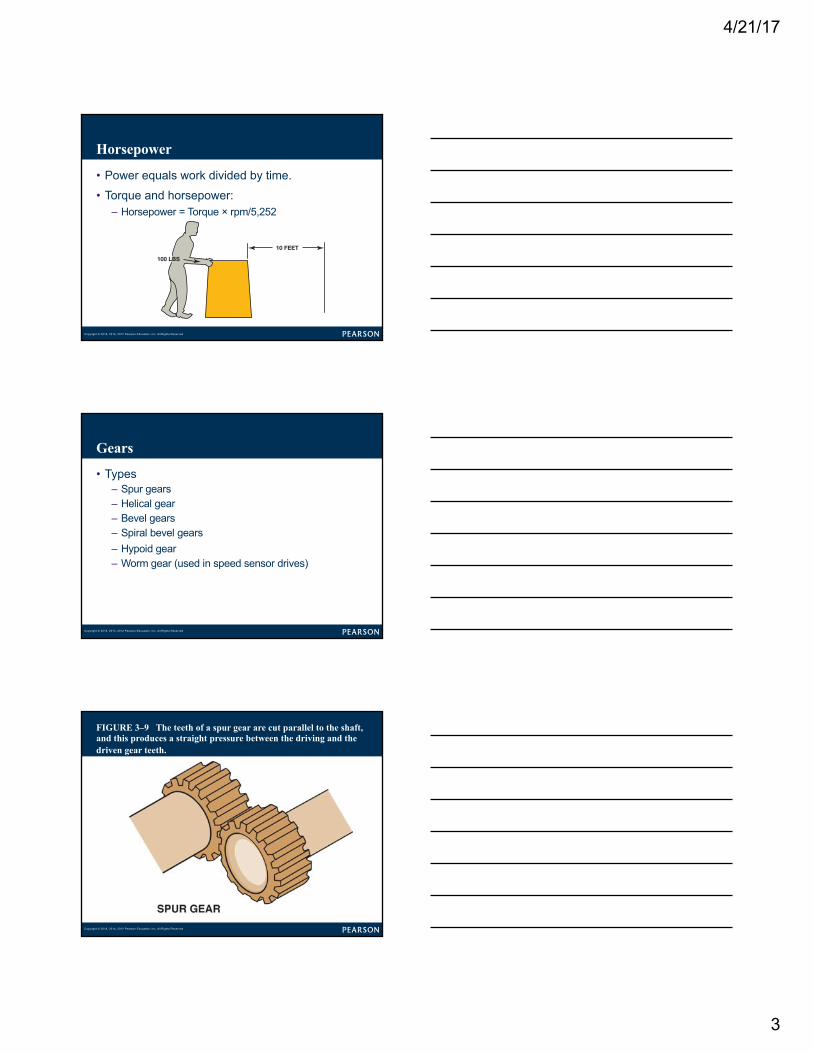
Gears
• Types
– Spur gears
– Helical gear
– Bevel gears
– Spiral bevel gears
– Hypoid gear
– Worm gear (used in speed sensor drives)
Copyright © 2018, 2014, 2012 Pearson Education, Inc. All Rights Reserved
FIGURE 3–9 The teeth of a spur gear are cut parallel to the shaft, and this produces a straight pressure between the driving and the driven gear teeth.
4/21/17
4
Copyright © 2018, 2014, 2012 Pearson Education, Inc. All Rights Reserved
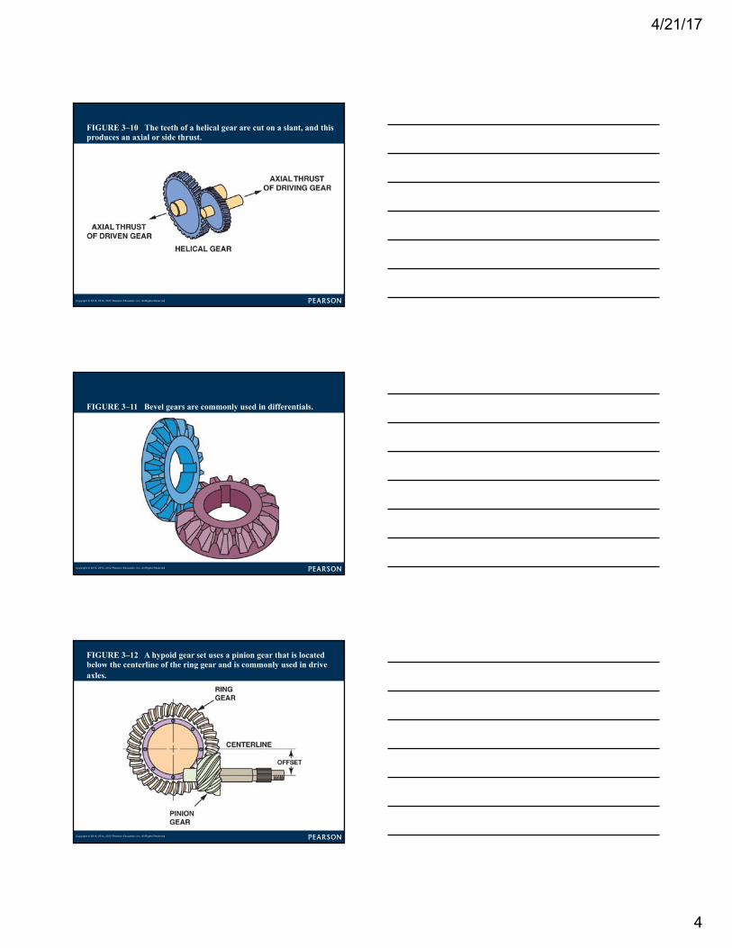
FIGURE 3–10 The teeth of a helical gear are cut on a slant, and this produces an axial or side thrust.
Copyright © 2018, 2014, 2012 Pearson Education, Inc. All Rights Reserved
FIGURE 3–11 Bevel gears are commonly used in differentials.
Copyright © 2018, 2014, 2012 Pearson Education, Inc. All Rights Reserved
FIGURE 3–12 A hypoid gear set uses a pinion gear that is located below the centerline of the ring gear and is commonly used in drive axles.
4/21/17
5
Copyright © 2018, 2014, 2012 Pearson Education, Inc. All Rights Reserved
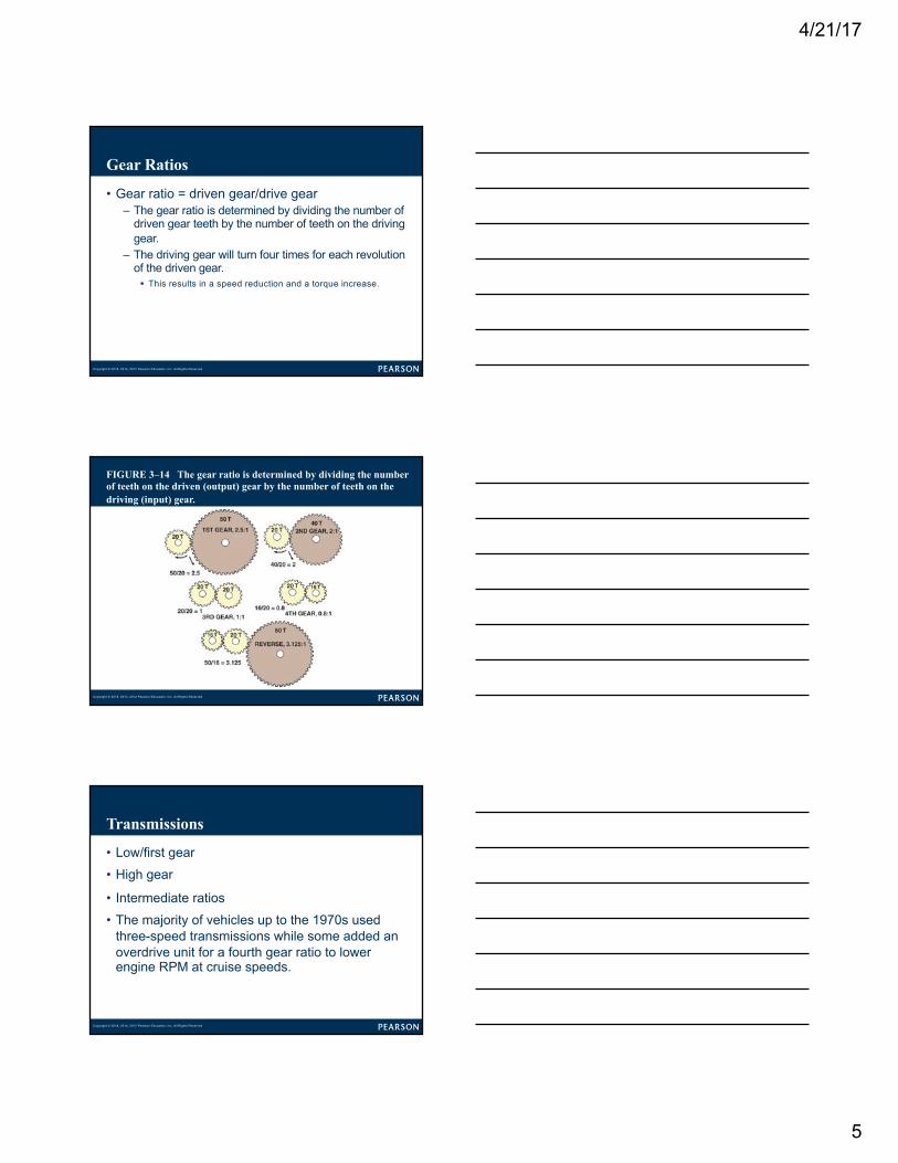
Gear Ratios
• Gear ratio = driven gear/drive gear
– The gear ratio is determined by dividing the number of
driven gear teeth by the number of teeth on the driving
gear.
– The driving gear will turn four times for each revolution
of the driven gear.
§ This results in a speed reduction and a torque increase.
Copyright © 2018, 2014, 2012 Pearson Education, Inc. All Rights Reserved
FIGURE 3–14 The gear ratio is determined by dividing the number of teeth on the driven (output) gear by the number of teeth on the driving (input) gear.
Copyright © 2018, 2014, 2012 Pearson Education, Inc. All Rights Reserved
Transmissions
• Low/first gear
• High gear
• Intermediate ratios
• The majority of vehicles up to the 1970s used
three-speed transmissions while some added an
overdrive unit for a fourth gear ratio to lower
engine RPM at cruise speeds.
4/21/17
6
Copyright © 2018, 2014, 2012 Pearson Education, Inc. All Rights Reserved
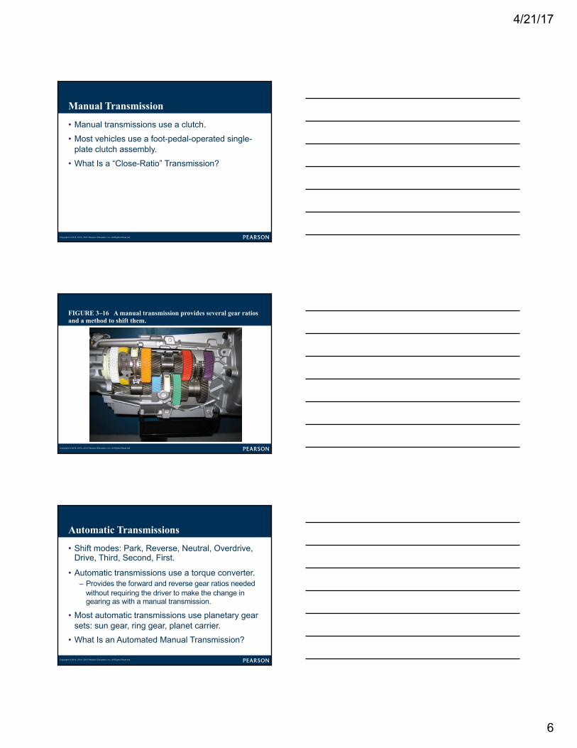
Manual Transmission
• Manual transmissions use a clutch.
• Most vehicles use a foot-pedal-operated single-
plate clutch assembly.
• What Is a “Close-Ratio” Transmission?
Copyright © 2018, 2014, 2012 Pearson Education, Inc. All Rights Reserved
FIGURE 3–16 A manual transmission provides several gear ratios and a method to shift them.
Copyright © 2018, 2014, 2012 Pearson Education, Inc. All Rights Reserved
Automatic Transmissions
• Shift modes: Park, Reverse, Neutral, Overdrive,
Drive, Third, Second, First.
• Automatic transmissions use a torque converter.
– Provides the forward and reverse gear ratios needed
without requiring the driver to make the change in
gearing as with a manual transmission.
• Most automatic transmissions use planetary gear
sets: sun gear, ring gear, planet carrier.
• What Is an Automated Manual Transmission?
4/21/17
7
Copyright © 2018, 2014, 2012 Pearson Education, Inc. All Rights Reserved
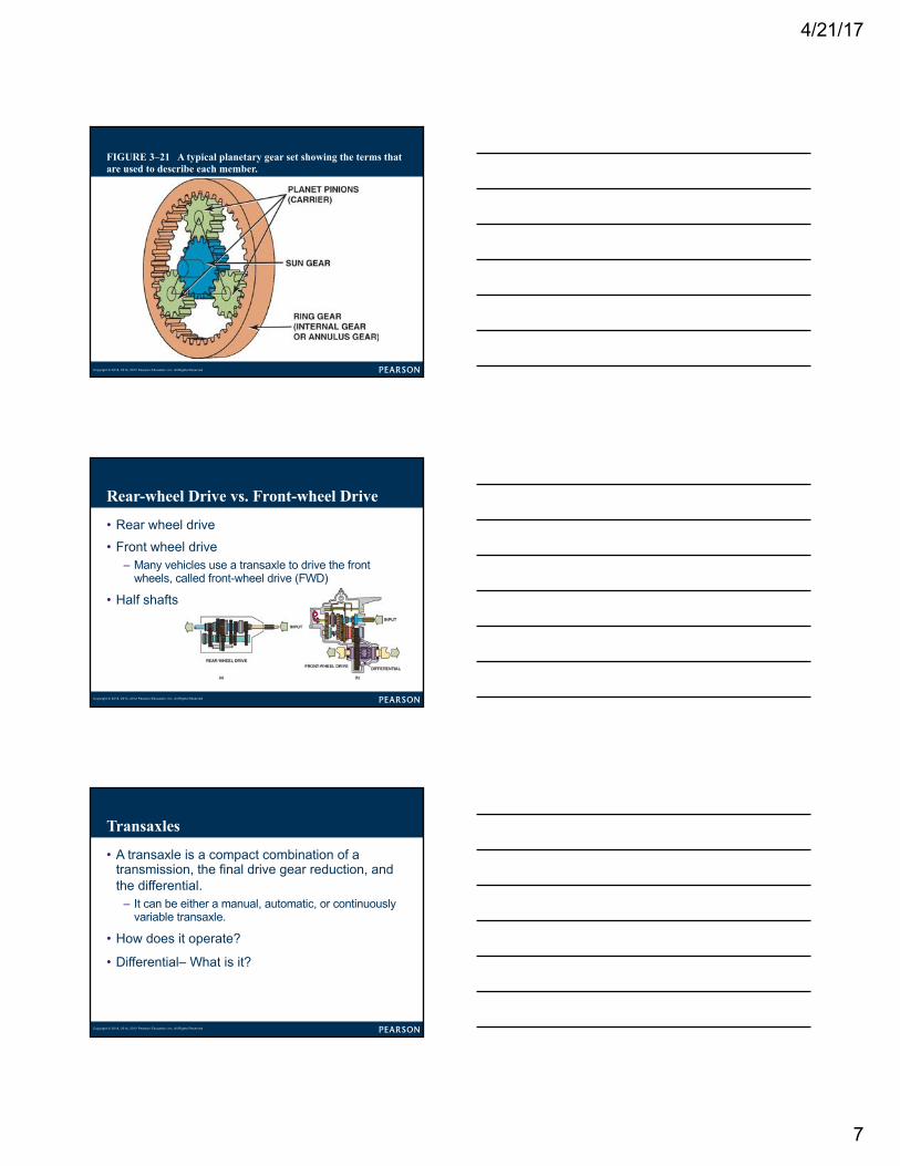
FIGURE 3–21 A typical planetary gear set showing the terms that are used to describe each member.
Copyright © 2018, 2014, 2012 Pearson Education, Inc. All Rights Reserved
Rear-wheel Drive vs. Front-wheel Drive
• Rear wheel drive
• Front wheel drive
– Many vehicles use a transaxle to drive the front
wheels, called front-wheel drive (FWD)
• Half shafts
Copyright © 2018, 2014, 2012 Pearson Education, Inc. All Rights Reserved
Transaxles
• A transaxle is a compact combination of a
transmission, the final drive gear reduction, and
the differential.
– It can be either a manual, automatic, or continuously
variable transaxle.
• How does it operate?
• Differential– What is it?
4/21/17
8
Copyright © 2018, 2014, 2012 Pearson Education, Inc. All Rights Reserved
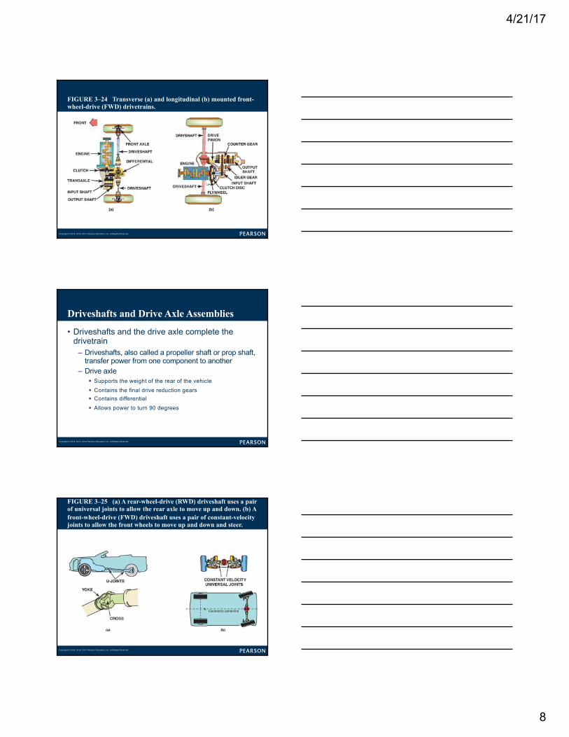
FIGURE 3–24 Transverse (a) and longitudinal (b) mounted front-wheel-drive (FWD) drivetrains.
Copyright © 2018, 2014, 2012 Pearson Education, Inc. All Rights Reserved
Driveshafts and Drive Axle Assemblies
• Driveshafts and the drive axle complete the
drivetrain
– Driveshafts, also called a propeller shaft or prop shaft,
transfer power from one component to another
– Drive axle
§ Supports the weight of the rear of the vehicle
§ Contains the final drive reduction gears
§ Contains differential
§ Allows power to turn 90 degrees
Copyright © 2018, 2014, 2012 Pearson Education, Inc. All Rights Reserved
FIGURE 3–25 (a) A rear-wheel-drive (RWD) driveshaft uses a pair of universal joints to allow the rear axle to move up and down. (b) A front-wheel-drive (FWD) driveshaft uses a pair of constant-velocity joints to allow the front wheels to move up and down and steer.
4/21/17
9
Copyright © 2018, 2014, 2012 Pearson Education, Inc. All Rights Reserved
Towing Capability
• Drivetrain requirements
– What are the features needed to tow a heavy load?
• SAE J2807 Standard
– Climbing test
– Acceleration test
– Launching
Copyright © 2018, 2014, 2012 Pearson Education, Inc. All Rights Reserved
Four-wheel Drive
• Four-wheel drive (4WD) is often designated as “4
x 4” and refers to a vehicle that has four driven
wheels.
• All-wheel-drive (AWD), also called full-time four-
wheel drive, vehicles are four-wheel-drive vehicles
equipped with a center (inner-axle) differential so
they can be operated on pavement in four-wheel
drive.
Copyright © 2018, 2014, 2012 Pearson Education, Inc. All Rights Reserved
Summary (1 of 2)
• Vehicles are built as rear-wheel drive, front-wheel
drive, and four- or all-wheel drive.
• Engines develop torque and the drivetrains modify
that torque to move the vehicle.
• A variety of gears are used to modify torque.
• The gear ratio is determined by dividing the
number of driven gear teeth by the number of
teeth on the driving gear.
4/21/17
10
Copyright © 2018, 2014, 2012 Pearson Education, Inc. All Rights Reserved
Summary (2 of 2)
• Manual transmissions use a clutch and automatic
transmissions use a torque converter.
• Driveshafts and the drive axle complete the
drivetrain.
• Four-wheel-drive and all-wheel-drive vehicles
have a transfer case or transfer gears and a
second drive axle.
Related Documents