VARIABLE SPEED COMPRESSORS ELECTRONIC INVERTER CF10B INVERTER MANUAL www.embraco.com April, 2020 Version 3.1

Welcome message from author
This document is posted to help you gain knowledge. Please leave a comment to let me know what you think about it! Share it to your friends and learn new things together.
Transcript
VARIABLE SPEED COMPRESSORSELECTRONIC INVERTER
CF10B INVERTER MANUAL
www.embraco.com April, 2020 Version 3.1
Contents
1 INTRODUCTION 1
2 TECHNICAL SPECIFICATIONS 22.1 Nomenclature . . . . . . . . . . . . . . . . . . . . . . . . . . . . . . . . . 22.2 Product specifications . . . . . . . . . . . . . . . . . . . . . . . . . . . . . 3
2.2.1 Label information . . . . . . . . . . . . . . . . . . . . . . . . . . . 52.2.2 Institute approval . . . . . . . . . . . . . . . . . . . . . . . . . . . 52.2.3 Product dimensions . . . . . . . . . . . . . . . . . . . . . . . . . 62.2.4 Connectors . . . . . . . . . . . . . . . . . . . . . . . . . . . . . . . 72.2.5 Cables . . . . . . . . . . . . . . . . . . . . . . . . . . . . . . . . . 8
2.3 Information about input inrush current . . . . . . . . . . . . . . . . . . . 9
3 INSTALLATION 103.1 Before you begin . . . . . . . . . . . . . . . . . . . . . . . . . . . . . . . . 10
3.1.1 Inverter cables arrangement . . . . . . . . . . . . . . . . . . . . 113.2 Inverter fixation and installation . . . . . . . . . . . . . . . . . . . . . . . 13
3.2.1 Compressor cable connection . . . . . . . . . . . . . . . . . . . . 153.2.2 VNE compressor cable connection . . . . . . . . . . . . . . . . . 163.2.3 Optional AC Fan switch control . . . . . . . . . . . . . . . . . . . 21
3.3 Safety Recommendations of Electrical Installation . . . . . . . . . . . . 213.4 Package information . . . . . . . . . . . . . . . . . . . . . . . . . . . . . . 22
3.4.1 Product discards . . . . . . . . . . . . . . . . . . . . . . . . . . . 23
4 OPERATION 254.1 Frequency control mode . . . . . . . . . . . . . . . . . . . . . . . . . . . 254.2 Drop-In control mode . . . . . . . . . . . . . . . . . . . . . . . . . . . . . 28
4.2.1 Default Drop-In . . . . . . . . . . . . . . . . . . . . . . . . . . . . 284.2.2 Smart Drop-In . . . . . . . . . . . . . . . . . . . . . . . . . . . . . 294.2.3 Defrost input (optional) . . . . . . . . . . . . . . . . . . . . . . . 304.2.4 Connection . . . . . . . . . . . . . . . . . . . . . . . . . . . . . . . 31
4.3 Serial control mode . . . . . . . . . . . . . . . . . . . . . . . . . . . . . . 324.3.1 Serial specifications and Internal Circuit . . . . . . . . . . . . . . 324.3.2 Commands . . . . . . . . . . . . . . . . . . . . . . . . . . . . . . . 34
5 DIAGNOSTICS 385.1 LED indication . . . . . . . . . . . . . . . . . . . . . . . . . . . . . . . . . 385.2 Troubleshooting . . . . . . . . . . . . . . . . . . . . . . . . . . . . . . . . 39
Chapter 1
INTRODUCTION
This document contains information regarding technical specifications, installationinstructions and functinality of CF10B Inverter family. It is intended to be used duringproject phase for proper specifications of system configuration and design, in orderto ensure the best application and performance available with use of Embraco’s Vari-able Capacity Compressors and avoid undesired issues.
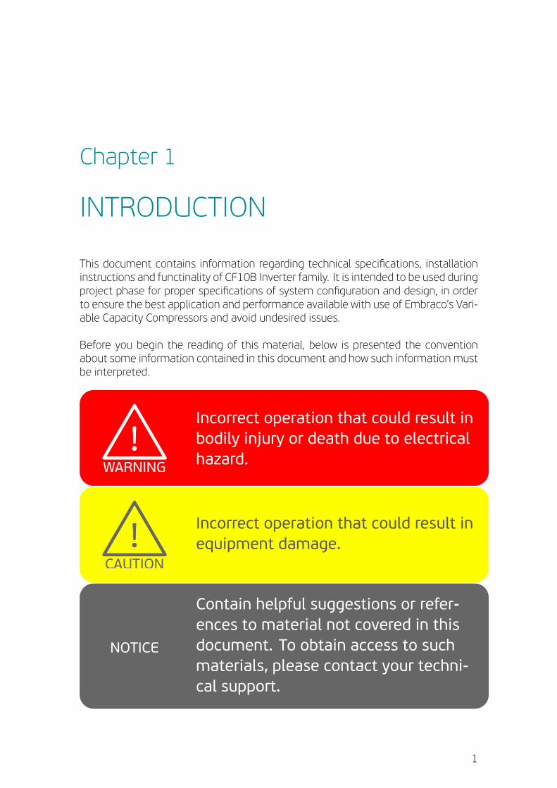
Before you begin the reading of this material, below is presented the conventionabout some information contained in this document and how such information mustbe interpreted.
!!
!!
WARNING
!!
NOTICE
CAUTION
Incorrect operation that could result inbodily injury or death due to electricalhazard.!!
!!
WARNING
!!
NOTICE
CAUTION
Incorrect operation that could result inequipment damage.
!!
!!
WARNING
!!
NOTICE
CAUTIONContain helpful suggestions or refer-ences to material not covered in thisdocument. To obtain access to suchmaterials, please contact your techni-cal support.
1
Chapter 2
TECHNICAL SPECIFICATIONS
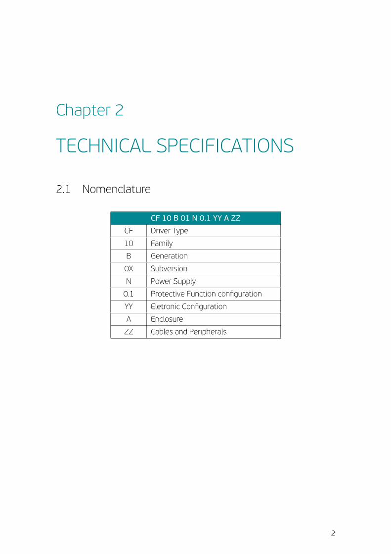
2.1 Nomenclature
CF 10 B 01 N 0.1 YY A ZZ
CF Driver Type
10 Family
B Generation
0X Subversion
N Power Supply
0.1 Protective Function configuration
YY Eletronic Configuration
A Enclosure
ZZ Cables and Peripherals
2
CHAPTER 2. TECHNICAL SPECIFICATIONS
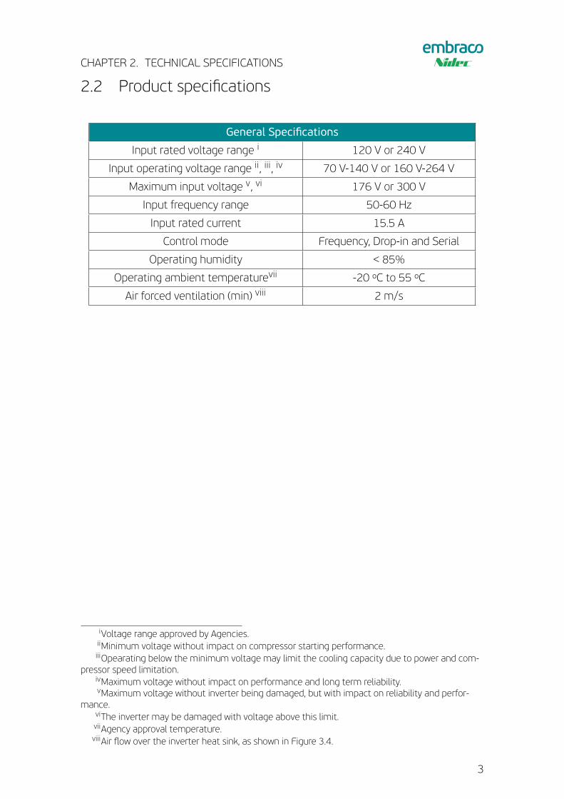
2.2 Product specifications
General Specifications
Input rated voltage range i 120 V or 240 V
Input operating voltage range ii, iii, iv 70 V-140 V or 160 V-264 V
Maximum input voltage v, vi 176 V or 300 V
Input frequency range 50-60 Hz
Input rated current 15.5 A
Control mode Frequency, Drop-in and Serial
Operating humidity < 85%
Operating ambient temperaturevii -20 ºC to 55 ºC
Air forced ventilation (min) viii 2 m/s
iVoltage range approved by Agencies.iiMinimum voltage without impact on compressor starting performance.iiiOpearating below the minimum voltage may limit the cooling capacity due to power and com-
pressor speed limitation.ivMaximum voltage without impact on performance and long term reliability.vMaximum voltage without inverter being damaged, but with impact on reliability and perfor-
mance.viThe inverter may be damaged with voltage above this limit.viiAgency approval temperature.viiiAir flow over the inverter heat sink, as shown in Figure 3.4.
3
CHAPTER 2. TECHNICAL SPECIFICATIONS
!!
!!
WARNING
!!
NOTICE
CAUTION
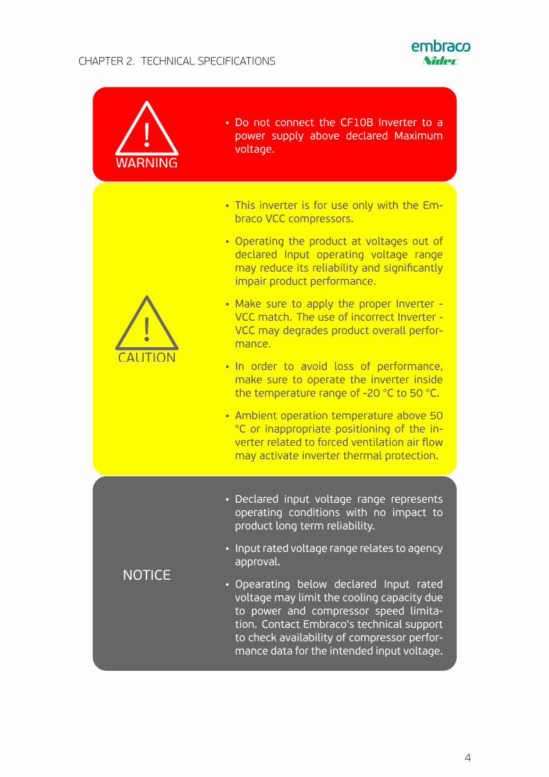
• Do not connect the CF10B Inverter to apower supply above declared Maximumvoltage.
!!
!!
WARNING
!!
NOTICE
CAUTION
• This inverter is for use only with the Em-braco VCC compressors.
• Operating the product at voltages out ofdeclared Input operating voltage rangemay reduce its reliability and significantlyimpair product performance.
• Make sure to apply the proper Inverter -VCC match. The use of incorrect Inverter -VCC may degrades product overall perfor-mance.
• In order to avoid loss of performance,make sure to operate the inverter insidethe temperature range of -20 °C to 50 °C.
• Ambient operation temperature above 50°C or inappropriate positioning of the in-verter related to forced ventilation air flowmay activate inverter thermal protection.
!!
!!
WARNING
!!
NOTICE
CAUTION
• Declared input voltage range representsoperating conditions with no impact toproduct long term reliability.
• Input rated voltage range relates to agencyapproval.
• Opearating below declared Input ratedvoltage may limit the cooling capacity dueto power and compressor speed limita-tion. Contact Embraco's technical supportto check availability of compressor perfor-mance data for the intended input voltage.
4
CHAPTER 2. TECHNICAL SPECIFICATIONS
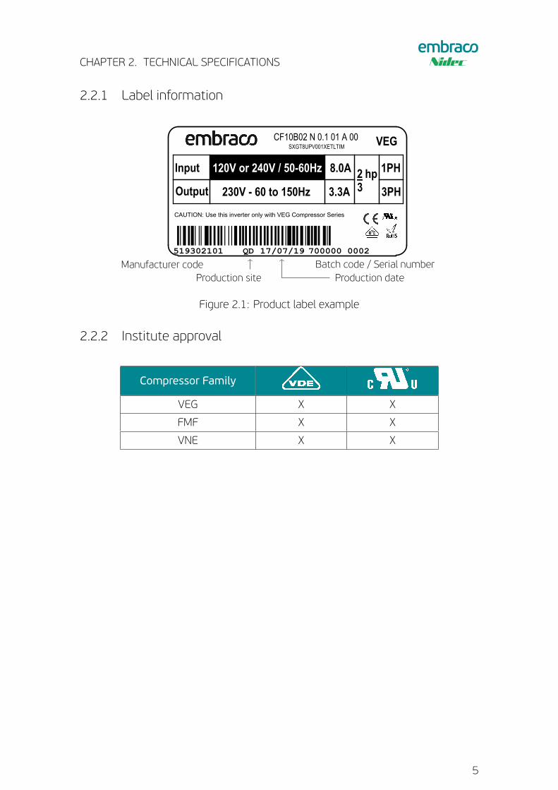
2.2.1 Label information
519302101 QD 17/07/19 700000 0002
CAUTION: Use this inverter only with VEG Compressor Series
Output
Input
230V - 60 to 150Hz
120V or 240V / 50-60Hz 8.0A
3.3A 3PH
1PH2 hp3
SXGT8UPV001XETLTIM
CF10B02 N 0.1 01 A 00 VEG
Manufacturer code Batch code / Serial numberProduction site Production date
Figure 2.1: Product label example
2.2.2 Institute approval
Compressor Family
VEG X X
FMF X X
VNE X X
5
CHAPTER 2. TECHNICAL SPECIFICATIONS
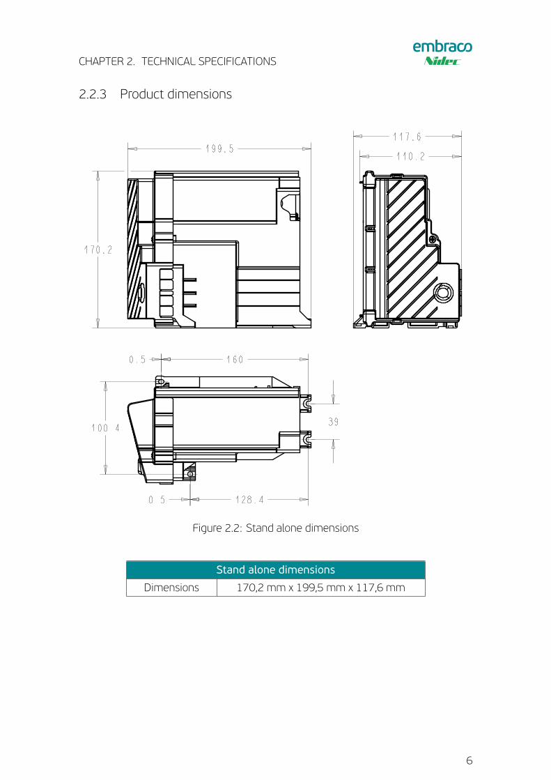
2.2.3 Product dimensions
199.5
170.2
117.6
39100.4
160
128.40.5
0.5
110.2
Figure 2.2: Stand alone dimensions
Stand alone dimensions
Dimensions 170,2 mm x 199,5 mm x 117,6 mm
6
CHAPTER 2. TECHNICAL SPECIFICATIONS
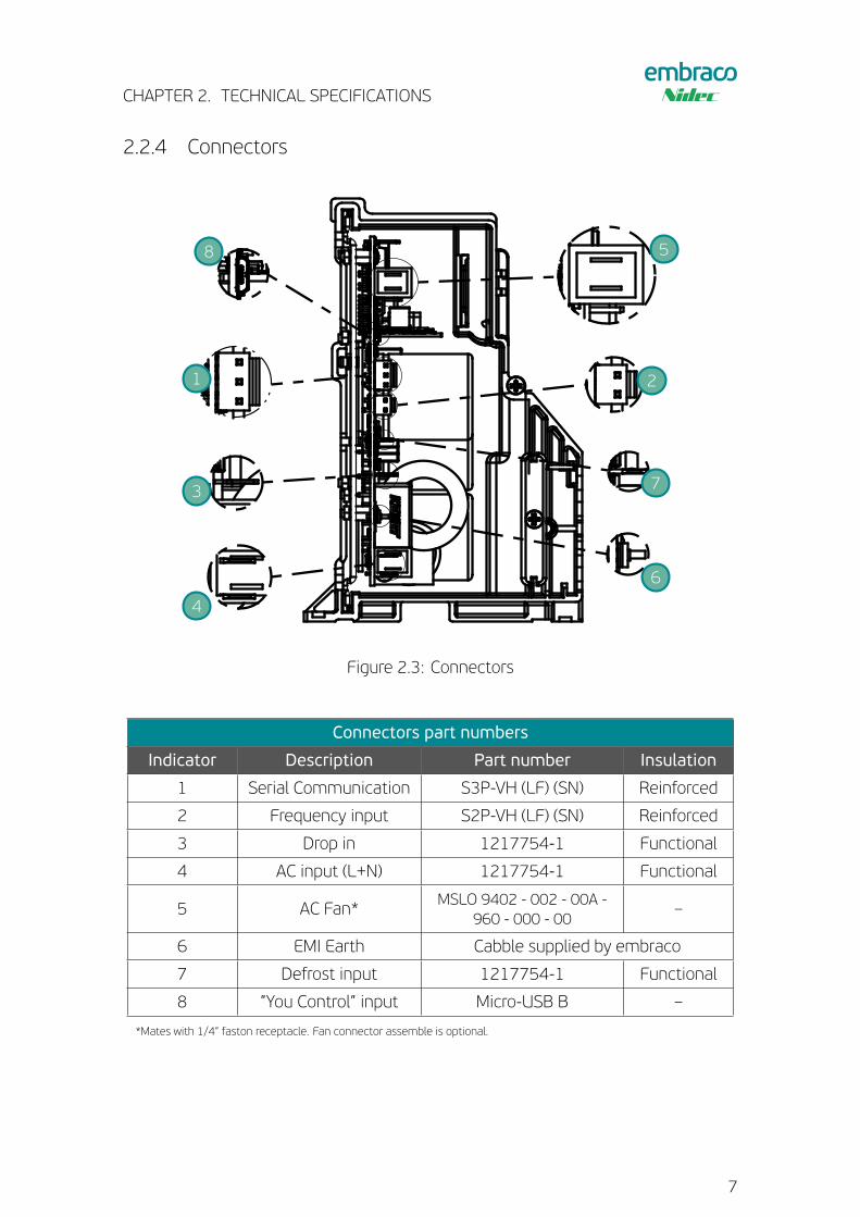
2.2.4 Connectors
1 2
3
4
5
6
7
8
Figure 2.3: Connectors
Connectors part numbers
Indicator Description Part number Insulation
1 Serial Communication S3P-VH (LF) (SN) Reinforced
2 Frequency input S2P-VH (LF) (SN) Reinforced
3 Drop in 1217754-1 Functional
4 AC input (L+N) 1217754-1 Functional
5 AC Fan* MSLO 9402 - 002 - 00A -960 - 000 - 00
–
6 EMI Earth Cabble supplied by embraco
7 Defrost input 1217754-1 Functional
8 ”You Control” input Micro-USB B –
*Mates with 1/4” faston receptacle. Fan connector assemble is optional.
7
CHAPTER 2. TECHNICAL SPECIFICATIONS
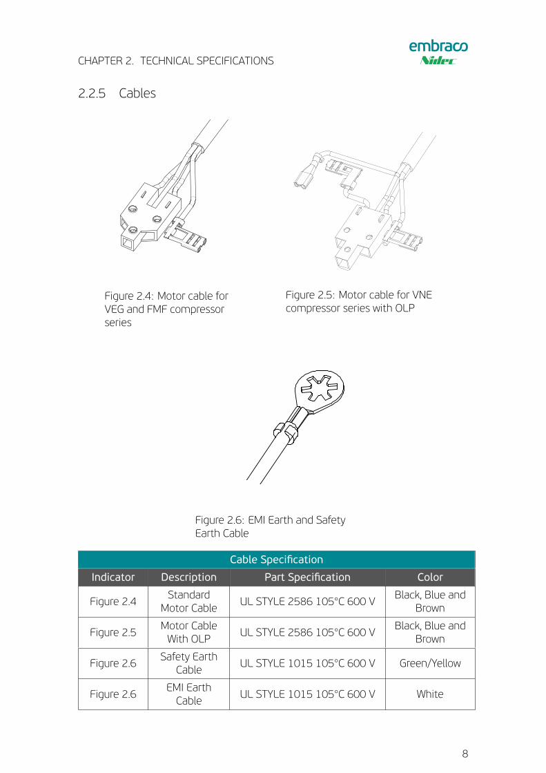
2.2.5 Cables
Figure 2.4: Motor cable forVEG and FMF compressorseries
Figure 2.5: Motor cable for VNEcompressor series with OLP
Figure 2.6: EMI Earth and SafetyEarth Cable
Cable Specification
Indicator Description Part Specification Color
Figure 2.4Standard
Motor CableUL STYLE 2586 105°C 600 V
Black, Blue andBrown
Figure 2.5Motor CableWith OLP
UL STYLE 2586 105°C 600 VBlack, Blue and
Brown
Figure 2.6Safety Earth
CableUL STYLE 1015 105°C 600 V Green/Yellow
Figure 2.6EMI EarthCable
UL STYLE 1015 105°C 600 V White
8
CHAPTER 2. TECHNICAL SPECIFICATIONS
!!
!!
WARNING
!!
NOTICE
CAUTION
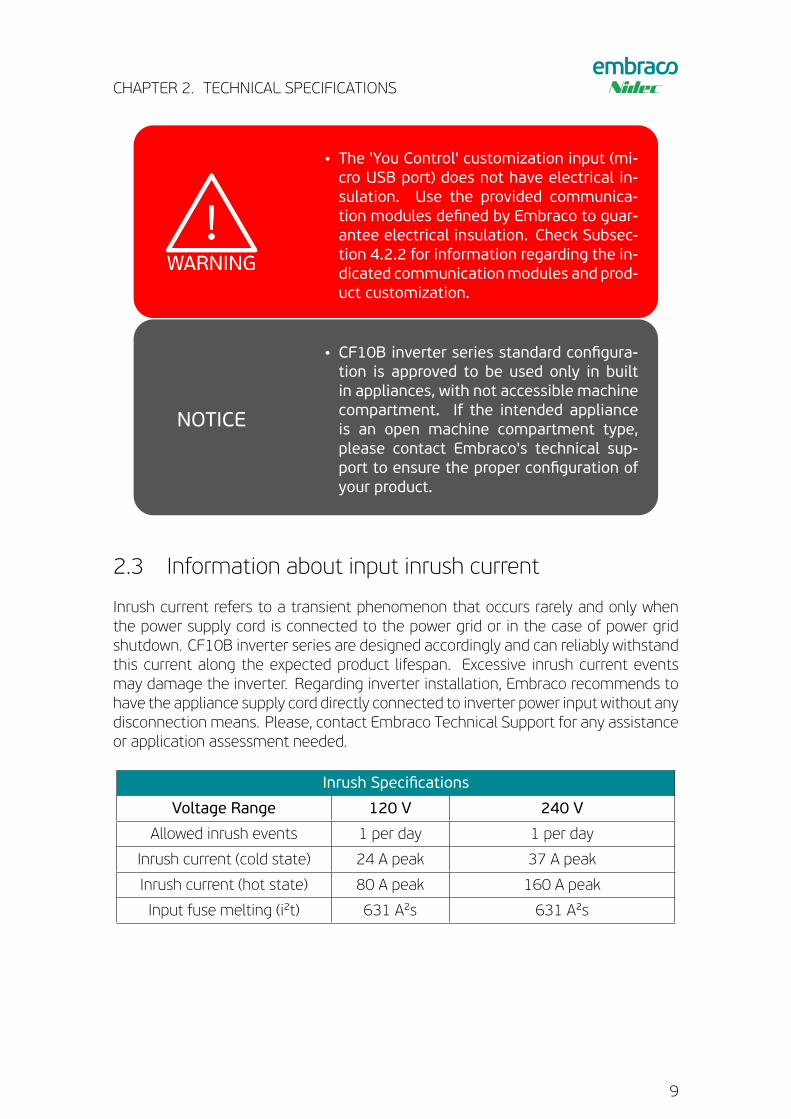
• The 'You Control' customization input (mi-cro USB port) does not have electrical in-sulation. Use the provided communica-tion modules defined by Embraco to guar-antee electrical insulation. Check Subsec-tion 4.2.2 for information regarding the in-dicated communicationmodules and prod-uct customization.
!!
!!
WARNING
!!
NOTICE
CAUTION • CF10B inverter series standard configura-tion is approved to be used only in builtin appliances, with not accessible machinecompartment. If the intended applianceis an open machine compartment type,please contact Embraco's technical sup-port to ensure the proper configuration ofyour product.
2.3 Information about input inrush current
Inrush current refers to a transient phenomenon that occurs rarely and only whenthe power supply cord is connected to the power grid or in the case of power gridshutdown. CF10B inverter series are designed accordingly and can reliably withstandthis current along the expected product lifespan. Excessive inrush current eventsmay damage the inverter. Regarding inverter installation, Embraco recommends tohave the appliance supply cord directly connected to inverter power input without anydisconnection means. Please, contact Embraco Technical Support for any assistanceor application assessment needed.
Inrush Specifications
Voltage Range 120 V 240 V
Allowed inrush events 1 per day 1 per day
Inrush current (cold state) 24 A peak 37 A peak
Inrush current (hot state) 80 A peak 160 A peak
Input fuse melting (i²t) 631 A²s 631 A²s
9
Chapter 3
INSTALLATION
3.1 Before you begin
!!
!!
WARNING
!!
NOTICE
CAUTION
• Make sure that CF10B Inverter will not bein direct contact with flames during as-sembly.
• The location where the Inverter willbe installed must be protected againstsplashed water from all directions.
• Do not open the Inverter enclosure. For in-stallation, remove only the Inverter Coverto make the electrical connections.
!!
!!
WARNING
!!
NOTICE
CAUTION
• Before you begin your installation observetechnical specifications and proper con-nections.
• To prevent damage to your inverter dur-ing and aster assembly, avoid contactingwith the following substances: Hydrocar-bons; Ester based oils (e.g.: compressoroil); Phenols; Amines; Ketenes; Automo-tive fluids such as grease, except glycoland heavy alcohol.
• Inverter is sensitive to Electrostatic Dis-charges. The environment must be prop-erly protected against ESD and workersthat handle the inverter must be Earthedthrough adequate ESD wrist strap andwear ESD gloves.
10
CHAPTER 3. INSTALLATION
!!
!!
WARNING
!!
NOTICE
CAUTION
• Take care with product handling until finalassembly.
• Do not hold by the wiring.
• Special care must be taken to avoid me-chanical impacts on the inverter during as-sembly process.
• Do not use the inverter if it drops duringhandling.
• Check if product is properly identified andif it's enclosure is without cracks.
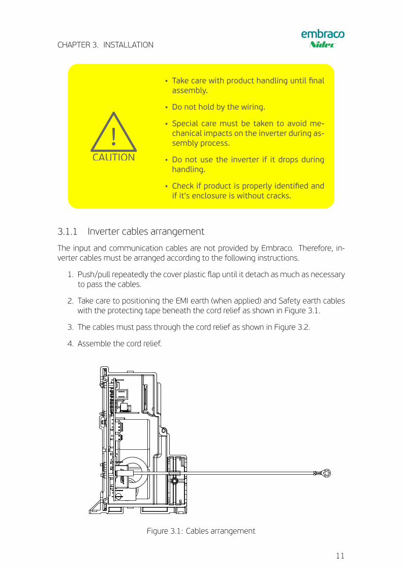
3.1.1 Inverter cables arrangement
The input and communication cables are not provided by Embraco. Therefore, in-verter cables must be arranged according to the following instructions.
1. Push/pull repeatedly the cover plastic flap until it detach as much as necessaryto pass the cables.
2. Take care to positioning the EMI earth (when applied) and Safety earth cableswith the protecting tape beneath the cord relief as shown in Figure 3.1.
3. The cables must pass through the cord relief as shown in Figure 3.2.
4. Assemble the cord relief.
Figure 3.1: Cables arrangement
11
CHAPTER 3. INSTALLATION
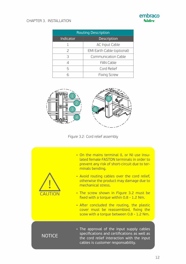
Routing Description
Indicator Description
1 AC Input Cable
2 EMI Earth Cable (optional)
3 Communication Cable
4 FAN Cable
5 Cord Relief
6 Fixing Screw
6
5
4
3
2
1
Figure 3.2: Cord relief assembly
!!
!!
WARNING
!!
NOTICE
CAUTION
• On the mains terminal (L or N) use insu-lated female FASTON terminals in order toprevent any risk of short-circuit due to ter-minals bending.
• Avoid routing cables over the cord relief,otherwise the product may damage due tomechanical stress.
• The screw shown in Figure 3.2 must befixed with a torque within 0.8 - 1.2 Nm.
• Aster concluded the routing, the plasticcover must be reassembled, fixing thescew with a torque between 0.8 - 1.2 Nm.
!!
!!
WARNING
!!
NOTICE
CAUTION
• The approval of the input supply cablesspecifications and certifications as well asthe cord relief interaction with the inputcables is customer responsability.
12
CHAPTER 3. INSTALLATION
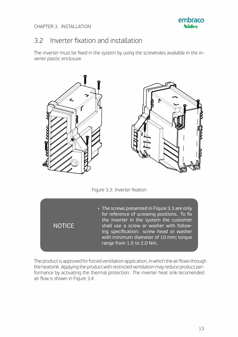
3.2 Inverter fixation and installation
The inverter must be fixed in the system by using the screwholes available in the in-verter plastic enclosure.
Figure 3.3: Inverter fixation
!!
!!
WARNING
!!
NOTICE
CAUTION• The screws presented in Figure 3.3 are onlyfor reference of screwing positions. To fixthe inverter in the system the customershall use a screw or washer with follow-ing specification: screw head or washerwith minimum diameter of 10 mm; torquerange from 1.5 to 2.0 Nm.
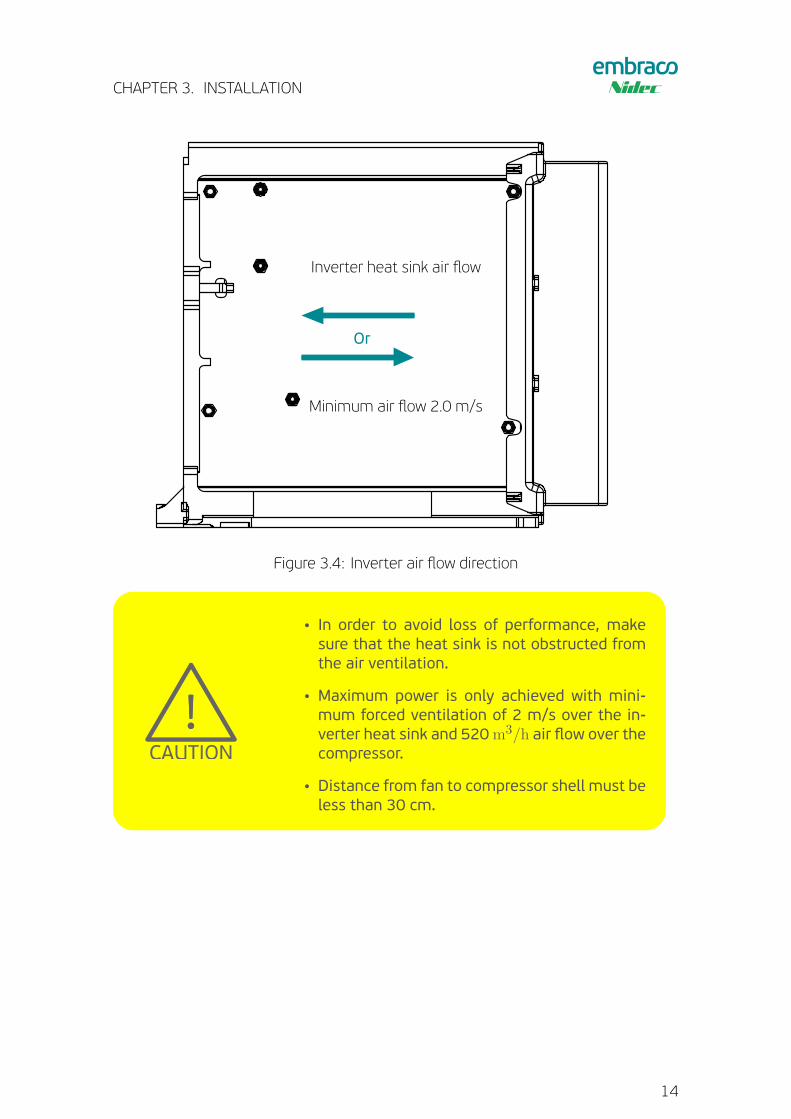
The product is approved for forced ventilation application, in which the air flows throughthe heatsink. Applying the product with restricted ventilationmay reduce product per-formance by activating the thermal protection. The inverter heat sink recomendedair flow is shown in Figure 3.4.
13
CHAPTER 3. INSTALLATION
Or
Inverter heat sink air flow
Minimum air flow 2.0 m/s
Figure 3.4: Inverter air flow direction
!!
!!
WARNING
!!
NOTICE
CAUTION
• In order to avoid loss of performance, makesure that the heat sink is not obstructed fromthe air ventilation.
• Maximum power is only achieved with mini-mum forced ventilation of 2 m/s over the in-verter heat sink and 520m3/h air flow over thecompressor.
• Distance from fan to compressor shell must beless than 30 cm.
14
CHAPTER 3. INSTALLATION
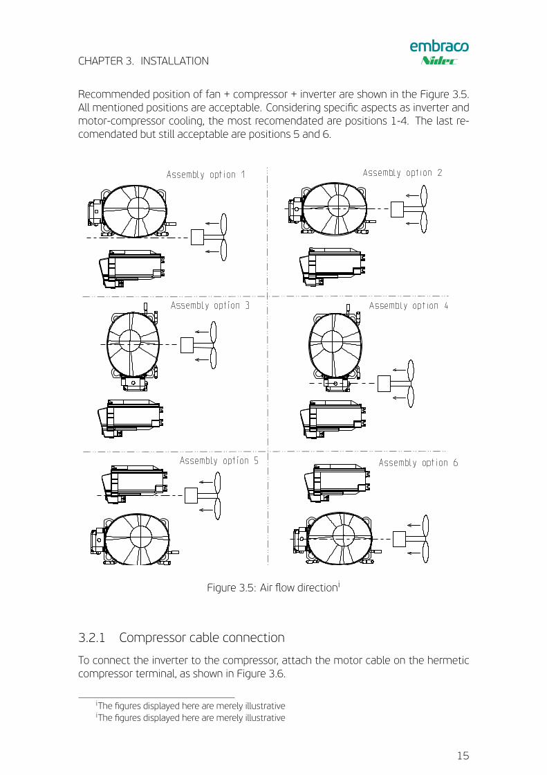
Recommended position of fan + compressor + inverter are shown in the Figure 3.5.All mentioned positions are acceptable. Considering specific aspects as inverter andmotor-compressor cooling, the most recomendated are positions 1-4. The last re-comendated but still acceptable are positions 5 and 6.
Assembly option 1 Assembly option 2
Assembly option 3 Assembly option 4
Assembly option 5 Assembly option 6
Figure 3.5: Air flow directioni
3.2.1 Compressor cable connection
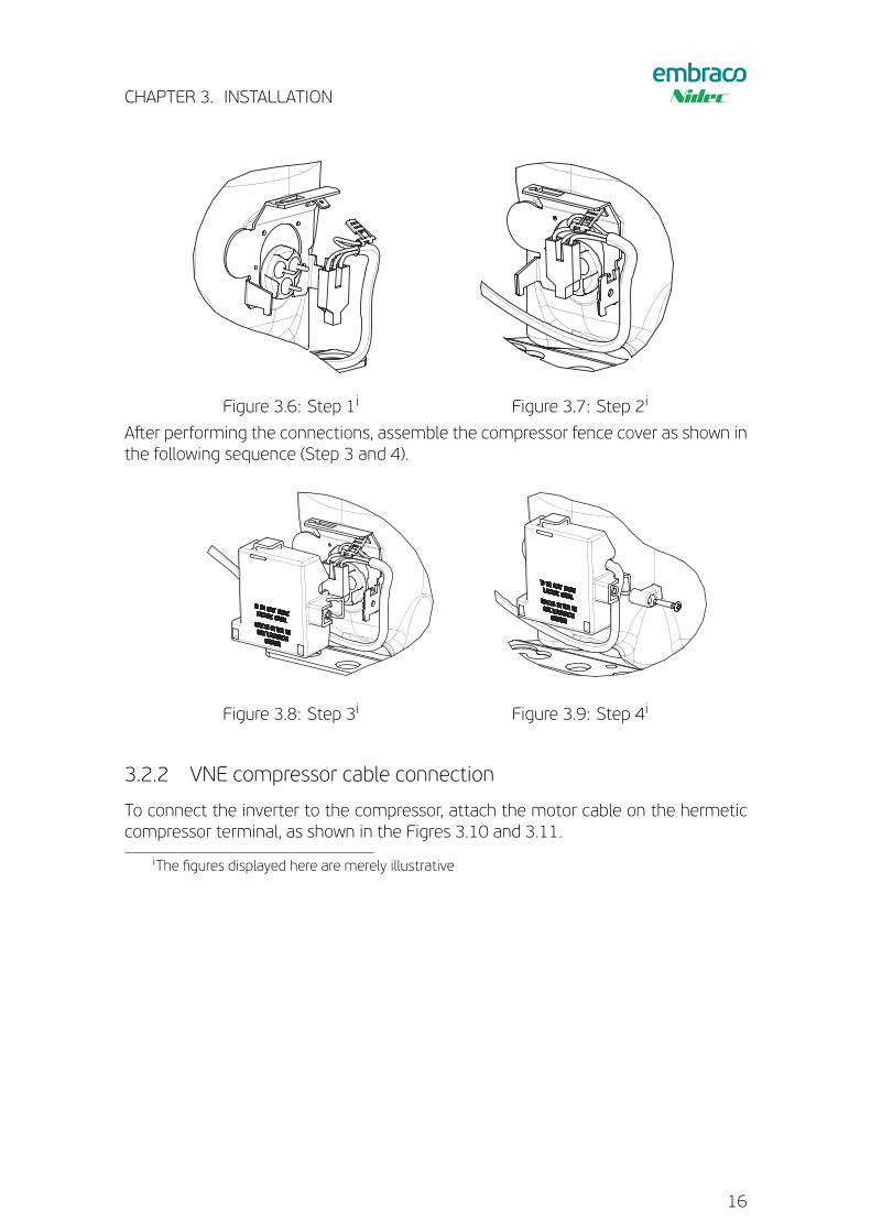
To connect the inverter to the compressor, attach the motor cable on the hermeticcompressor terminal, as shown in Figure 3.6.
iThe figures displayed here are merely illustrativeiThe figures displayed here are merely illustrative
15
CHAPTER 3. INSTALLATION
Figure 3.6: Step 1i Figure 3.7: Step 2i
Aster performing the connections, assemble the compressor fence cover as shown inthe following sequence (Step 3 and 4).
Figure 3.8: Step 3i Figure 3.9: Step 4i
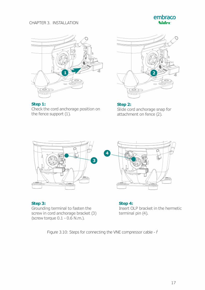
3.2.2 VNE compressor cable connection
To connect the inverter to the compressor, attach the motor cable on the hermeticcompressor terminal, as shown in the Figres 3.10 and 3.11.
iThe figures displayed here are merely illustrative
16
CHAPTER 3. INSTALLATION
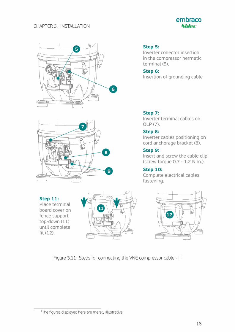
Step 1:Check the cord anchorage position onthe fence support (1).
Step 3:Grounding terminal to fasten thescrew in cord anchorage bracket (3)(screw torque 0.1 - 0.6 N.m.).
Step 4:Insert OLP bracket in the hermeticterminal pin (4).
Step 2:Slide cord anchorage snap forattachment on fence (2).
2
3
4
1
Figure 3.10: Steps for connecting the VNE compressor cable - Ii
17
CHAPTER 3. INSTALLATION
Figure 3.11: Steps for connecting the VNE compressor cable - IIi
iThe figures displayed here are merely illustrative
18
CHAPTER 3. INSTALLATION
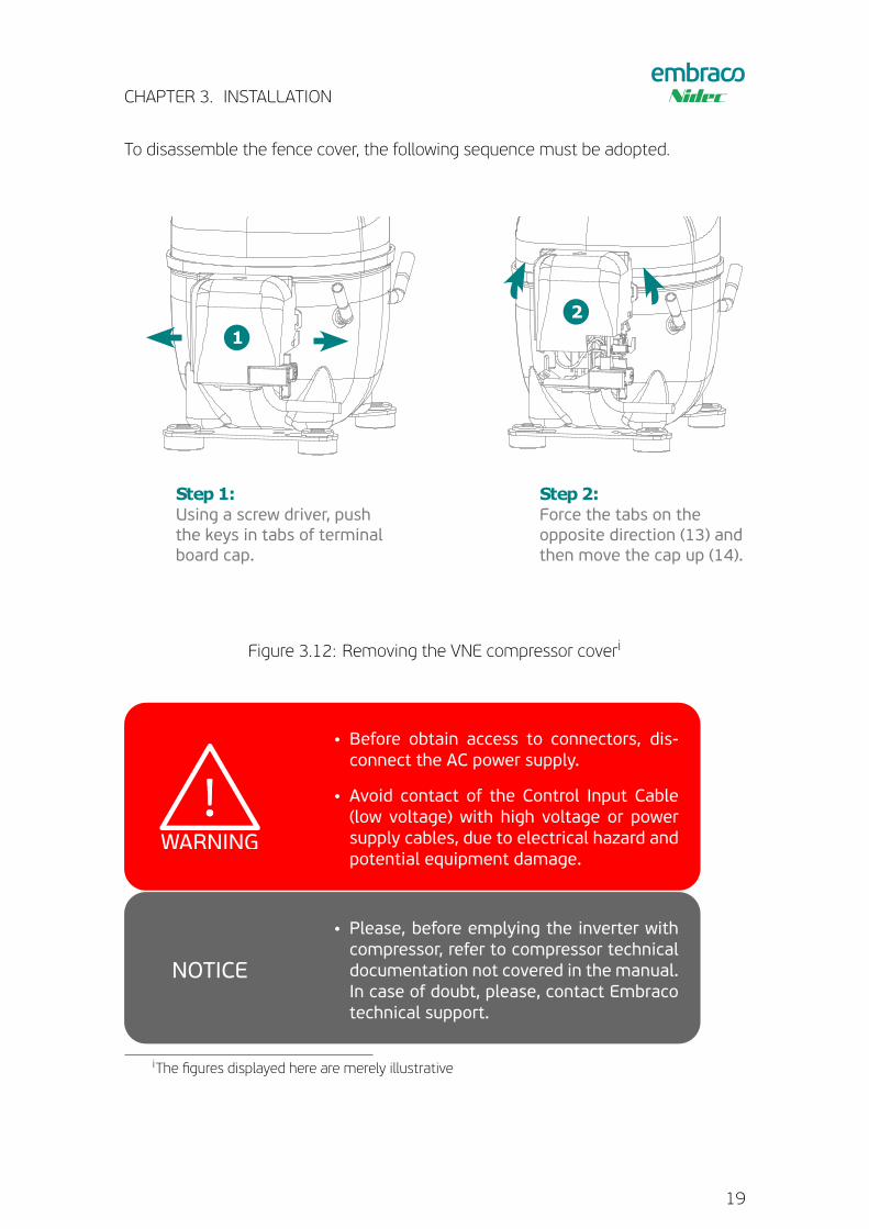
To disassemble the fence cover, the following sequence must be adopted.
Step 1:Using a screw driver, pushthe keys in tabs of terminalboard cap.
Step 2:Force the tabs on theopposite direction (13) andthen move the cap up (14).
3. OperationTurning on your VNE
FeaturesControl models
Drop-in Frequency Serial
Compatible for mechanicalthermostat contact (on/of )
yes no no
Inverter decides the best speed yes no no
Thermostat decides the bestspeed
no yes yes
Inverter send functional data(power, voltage, failures)
no no yes
1
2
Application
Figure 3.12: Removing the VNE compressor coveri
!!
!!
WARNING
!!
NOTICE
CAUTION
• Before obtain access to connectors, dis-connect the AC power supply.
• Avoid contact of the Control Input Cable(low voltage) with high voltage or powersupply cables, due to electrical hazard andpotential equipment damage.
!!
!!
WARNING
!!
NOTICE
CAUTION
• Please, before emplying the inverter withcompressor, refer to compressor technicaldocumentation not covered in the manual.In case of doubt, please, contact Embracotechnical support.
iThe figures displayed here are merely illustrative
19
CHAPTER 3. INSTALLATION
!!
!!
WARNING
!!
NOTICE
CAUTION
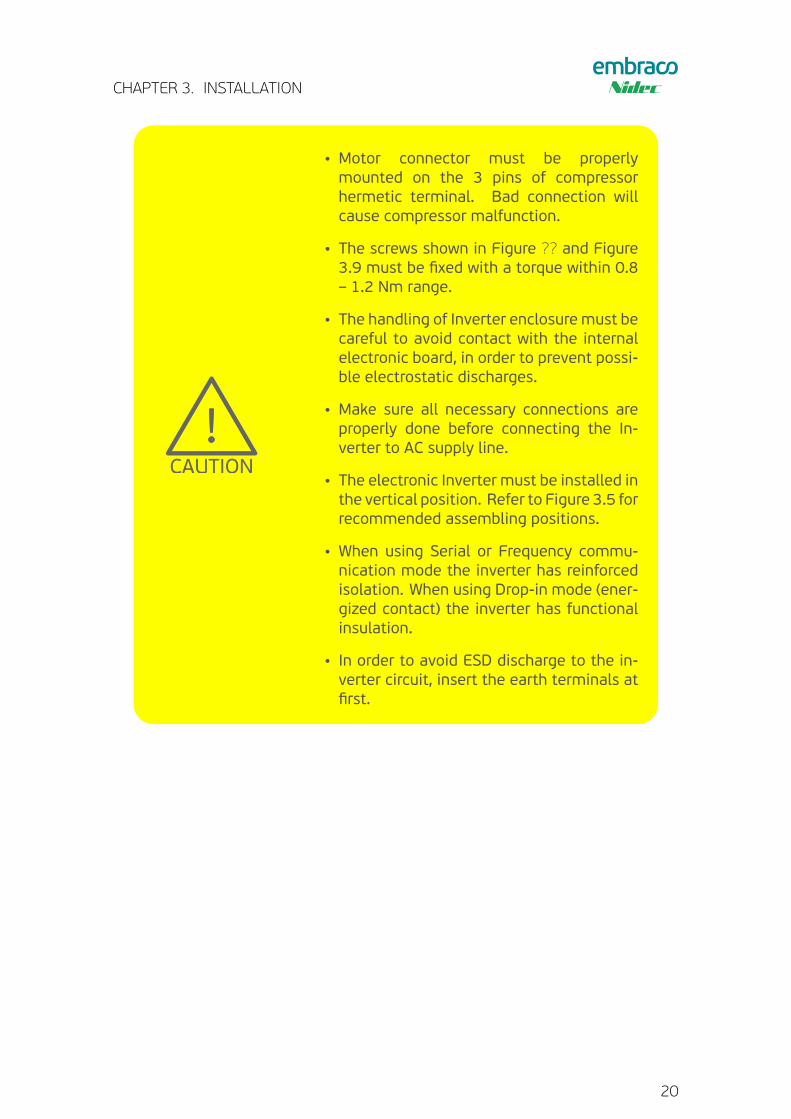
• Motor connector must be properlymounted on the 3 pins of compressorhermetic terminal. Bad connection willcause compressor malfunction.
• The screws shown in Figure ?? and Figure3.9 must be fixed with a torque within 0.8– 1.2 Nm range.
• The handling of Inverter enclosure must becareful to avoid contact with the internalelectronic board, in order to prevent possi-ble electrostatic discharges.
• Make sure all necessary connections areproperly done before connecting the In-verter to AC supply line.
• The electronic Inverter must be installed inthe vertical position. Refer to Figure 3.5 forrecommended assembling positions.
• When using Serial or Frequency commu-nication mode the inverter has reinforcedisolation. When using Drop-in mode (ener-gized contact) the inverter has functionalinsulation.
• In order to avoid ESD discharge to the in-verter circuit, insert the earth terminals atfirst.
20
CHAPTER 3. INSTALLATION
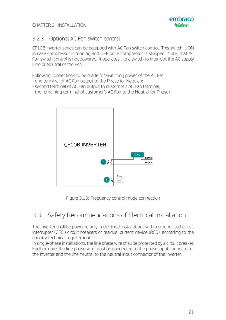
3.2.3 Optional AC Fan switch control
CF10B inverter series can be equipped with AC Fan switch control. This switch is ONin case compressor is running and OFF once compressor is stopped. Note, that ACFan switch control is not powered. It operates like a switch to interrupt the AC supplyLine or Neutral of the FAN.
Following connections to be made for switching power of the AC Fan:- one terminal of AC Fan output to the Phase (or Neutral);- second terminal of AC Fan output to customer’s AC Fan terminal;- the remaining terminal of customer’s AC Fan to the Neutral (or Phase).
Figure 3.13: Frequency control mode connection
3.3 Safety Recommendations of Electrical Installation
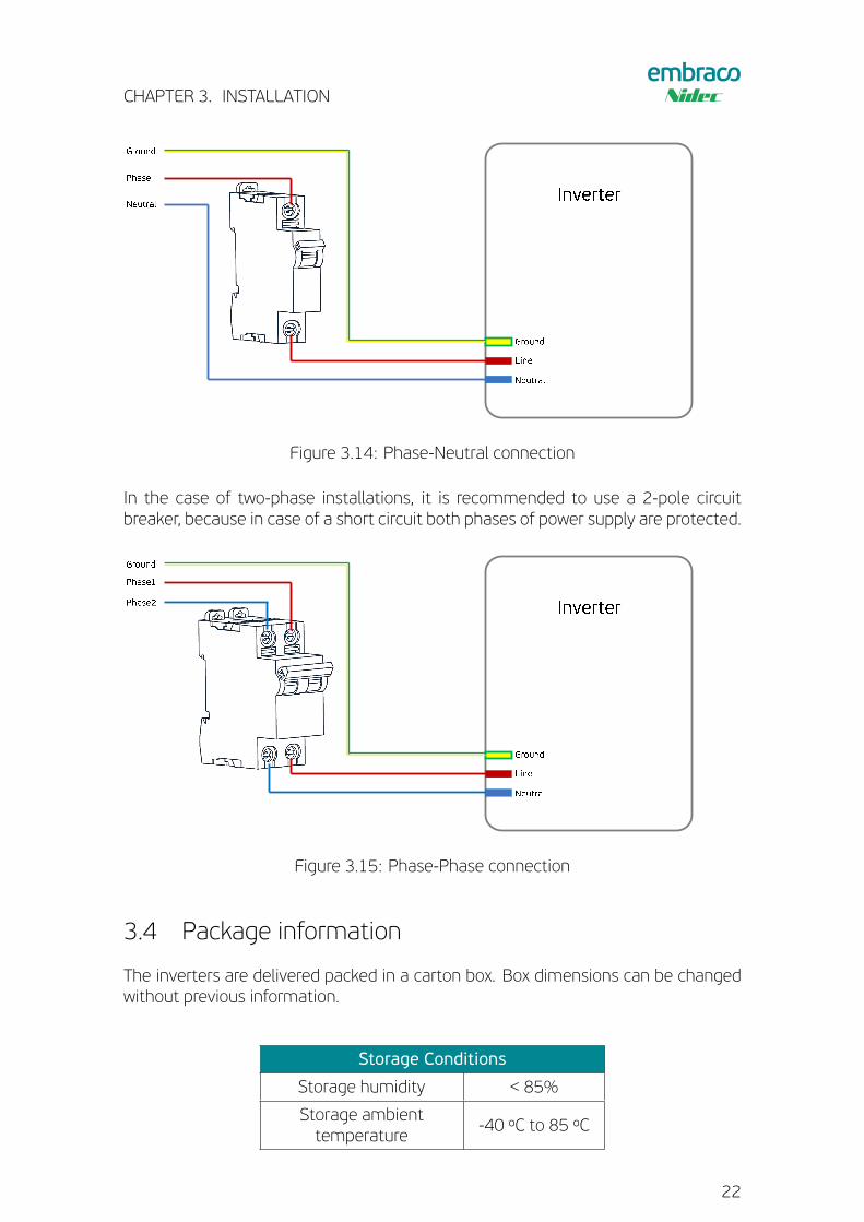
The Inverter shall be powered only in electrical installations with a ground fault circuitinterrupter (GFCI) circuit breakers or residual current device (RCD), according to thecountry technical requirement.In single-phase installations, the line phase wire shall be protected by a circuit breaker.Furthermore, the line phase wire must be connected to the phase input connector ofthe inverter and the line neutral to the neutral input connector of the inverter.
21
CHAPTER 3. INSTALLATION
Figure 3.14: Phase-Neutral connection
In the case of two-phase installations, it is recommended to use a 2-pole circuitbreaker, because in case of a short circuit both phases of power supply are protected.
Figure 3.15: Phase-Phase connection
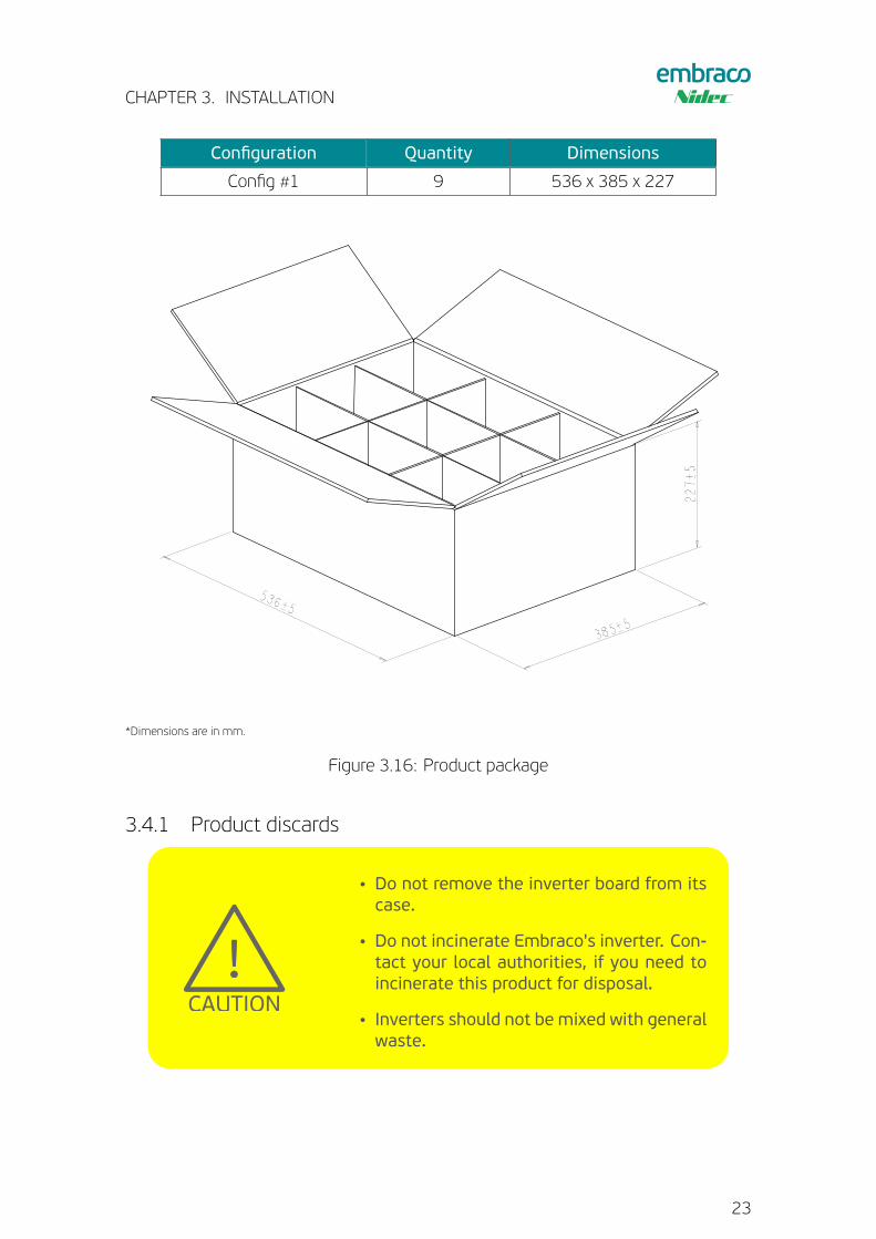
3.4 Package information
The inverters are delivered packed in a carton box. Box dimensions can be changedwithout previous information.
Storage Conditions
Storage humidity < 85%
Storage ambienttemperature
-40 ºC to 85 ºC
22
CHAPTER 3. INSTALLATION
Configuration Quantity Dimensions
Config #1 9 536 x 385 x 227
536±5
227±5
385±5
*Dimensions are in mm.
Figure 3.16: Product package
3.4.1 Product discards!!
!!
WARNING
!!
NOTICE
CAUTION
• Do not remove the inverter board from itscase.
• Do not incinerate Embraco's inverter. Con-tact your local authorities, if you need toincinerate this product for disposal.
• Inverters should not be mixed with generalwaste.
23

CHAPTER 3. INSTALLATION
!!
!!
WARNING
!!
NOTICE
CAUTION
• If you wish to discard this product, pleasecontact your local authorities or dealer forthe correct method of disposal, for propertreatment, recovery and recycling.
• The product package and its internal par-titions are made of carton and can be dis-posed as recyclable waste.
• This device is RoHS compliant, neverthe-less the correct disposal of this product willhelp to save valuable resources and pre-vent any potential negative effects on hu-man health and the environment (e.g.: toavoid ground disperse) which could other-wise arise from inappropriate handling.
24
Chapter 4
OPERATION
The CF10B Inverter have support for Serial, Frequency and Drop-In communicationmodes.
!!
!!
WARNING
!!
NOTICE
CAUTION• The inverter is assembled with all commu-nication modes and the control mode ischosen automatically by the inverter.
• Output frequency and motor speed mayhave reduced range based on maximumworking conditions of the respective com-pressor, not following some specific setpoint conditions. For detailed operatingrange of the selected compressor, pleasecontact Embraco Technical Support.
4.1 Frequency control mode
In this operation mode the compressor speed is controled through a frequency signalsent to the inverter. Usually this signal is provided by an electronic thermostat.The frequency signal is a digital square wave and its characteristics are described onSignal specification table and figure below.
25
CHAPTER 4. OPERATION
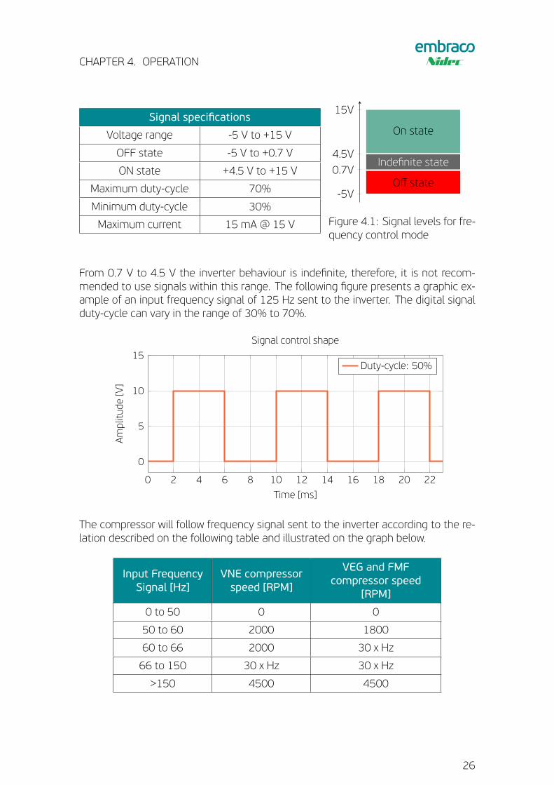
Signal specifications
Voltage range -5 V to +15 V
OFF state -5 V to +0.7 V
ON state +4.5 V to +15 V
Maximum duty-cycle 70%
Minimum duty-cycle 30%
Maximum current 15 mA @ 15 V
-5V
0.7V
4.5V
15V
Off state
Indefinite state
On state
Figure 4.1: Signal levels for fre-quency control mode
From 0.7 V to 4.5 V the inverter behaviour is indefinite, therefore, it is not recom-mended to use signals within this range. The following figure presents a graphic ex-ample of an input frequency signal of 125 Hz sent to the inverter. The digital signalduty-cycle can vary in the range of 30% to 70%.
0 2 4 6 8 10 12 14 16 18 20 22
0
5
10
15
Time [ms]
Amplitude
[V]
Signal control shape
Duty-cycle: 50%
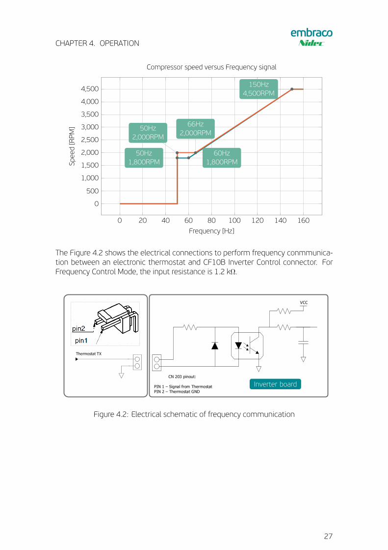
The compressor will follow frequency signal sent to the inverter according to the re-lation described on the following table and illustrated on the graph below.
Input FrequencySignal [Hz]
VNE compressorspeed [RPM]
VEG and FMFcompressor speed
[RPM]
0 to 50 0 0
50 to 60 2000 1800
60 to 66 2000 30 x Hz
66 to 150 30 x Hz 30 x Hz
>150 4500 4500
26
CHAPTER 4. OPERATION
0 20 40 60 80 100 120 140 160
0
500
1,000
1,500
2,000
2,500
3,000
3,500
4,000
4,500
66Hz2,000RPM
50Hz2,000RPM
50Hz1,800RPM
150Hz4,500RPM
60Hz1,800RPM
Frequency [Hz]
Speed[RPM]
Compressor speed versus Frequency signal
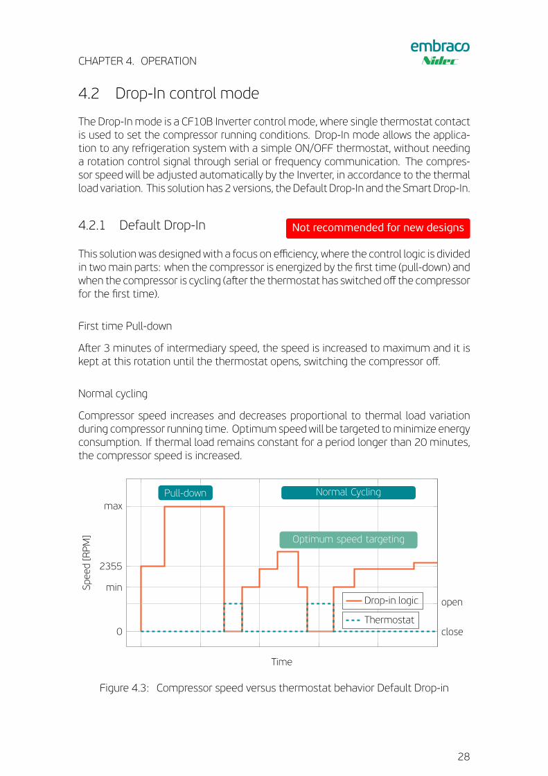
The Figure 4.2 shows the electrical connections to perform frequency conmmunica-tion between an electronic thermostat and CF10B Inverter Control connector. ForFrequency Control Mode, the input resistance is 1.2 kΩ.
VCC
CN 203 pinout:
PIN 1 – Signal from ThermostatPIN 2 – Thermostat GND
3
2
1
VCC
Inverter RX
Inverter TX
VCC
CN 204 pinout:
PIN 1 – Signal from ThermostatPIN 2 – Thermostat GNDPIN 3 – Signal toThermostat
Collector currentrange: 1 mA to 2 mA
CN 204
1
3
2
Thermostat TX
Thermostat RX
VCC
Thermostat TX
Inverter board
Figure 4.2: Electrical schematic of frequency communication
27
CHAPTER 4. OPERATION
4.2 Drop-In control mode
The Drop-In mode is a CF10B Inverter control mode, where single thermostat contactis used to set the compressor running conditions. Drop-In mode allows the applica-tion to any refrigeration system with a simple ON/OFF thermostat, without needinga rotation control signal through serial or frequency communication. The compres-sor speed will be adjusted automatically by the Inverter, in accordance to the thermalload variation. This solution has 2 versions, the Default Drop-In and the Smart Drop-In.
4.2.1 Default Drop-In Not recommended for new designs
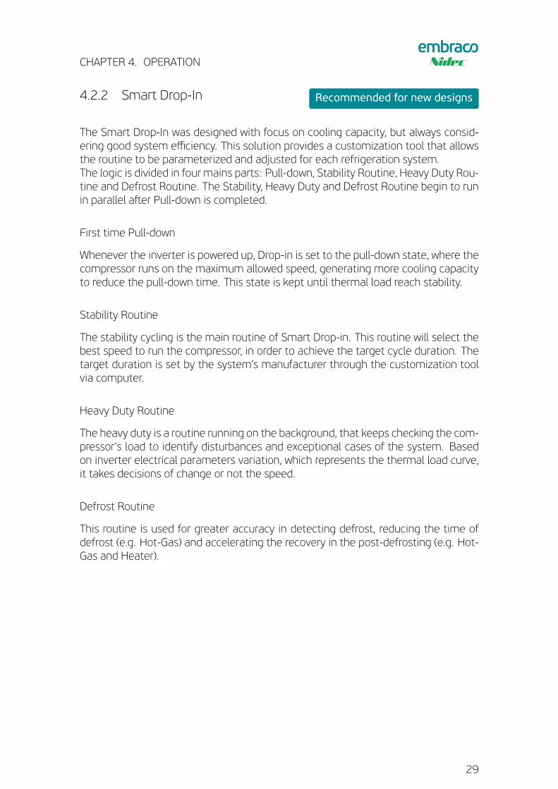
This solution was designed with a focus on efficiency, where the control logic is dividedin twomain parts: when the compressor is energized by the first time (pull-down) andwhen the compressor is cycling (aster the thermostat has switched off the compressorfor the first time).
First time Pull-down
Aster 3 minutes of intermediary speed, the speed is increased to maximum and it iskept at this rotation until the thermostat opens, switching the compressor off.
Normal cycling
Compressor speed increases and decreases proportional to thermal load variationduring compressor running time. Optimum speed will be targeted tominimize energyconsumption. If thermal load remains constant for a period longer than 20 minutes,the compressor speed is increased.
0
min
2355
maxPull-down Normal Cycling
Optimum speed targeting
Time
Speed[RPM]
Drop-in logic
close
open
Thermostat
Figure 4.3: Compressor speed versus thermostat behavior Default Drop-in
28
CHAPTER 4. OPERATION
4.2.2 Smart Drop-In Recommended for new designs
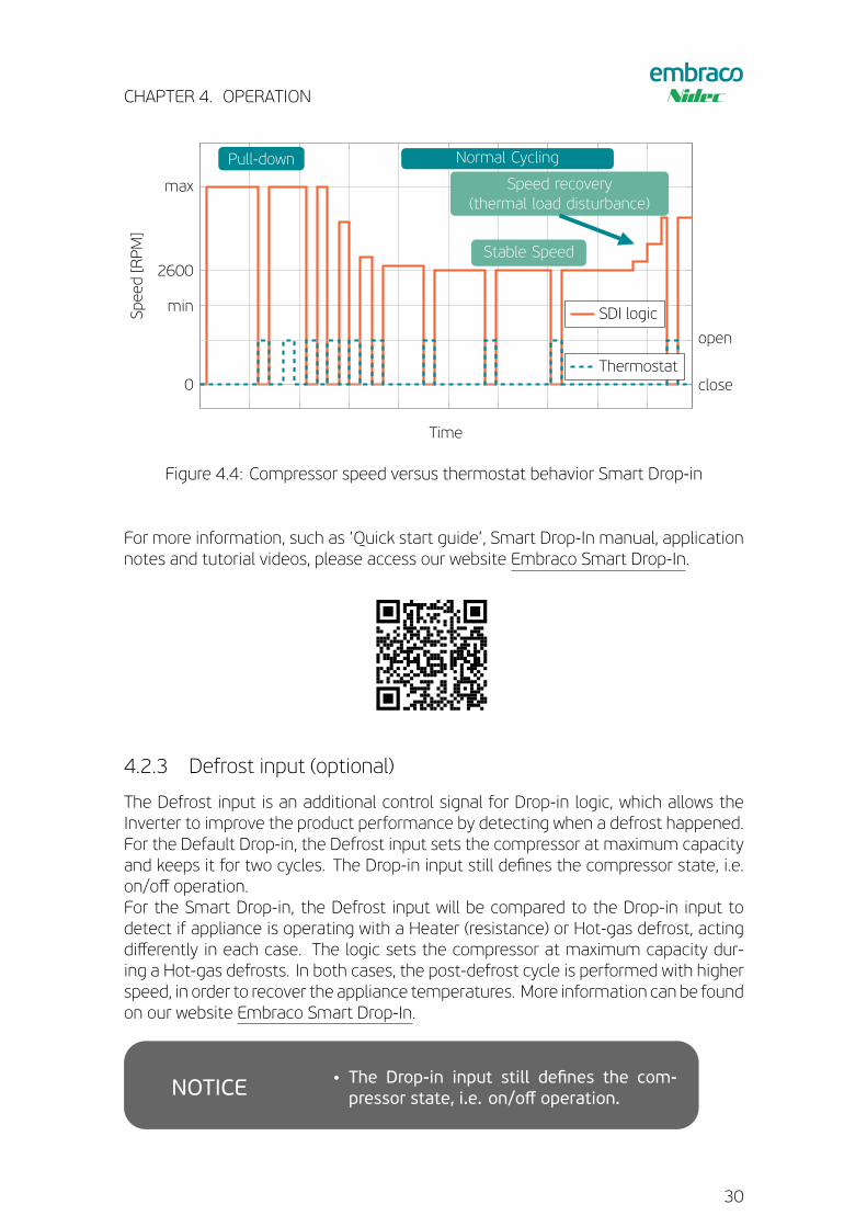
The Smart Drop-In was designed with focus on cooling capacity, but always consid-ering good system efficiency. This solution provides a customization tool that allowsthe routine to be parameterized and adjusted for each refrigeration system.The logic is divided in four mains parts: Pull-down, Stability Routine, Heavy Duty Rou-tine and Defrost Routine. The Stability, Heavy Duty and Defrost Routine begin to runin parallel aster Pull-down is completed.
First time Pull-down
Whenever the inverter is powered up, Drop-in is set to the pull-down state, where thecompressor runs on the maximum allowed speed, generating more cooling capacityto reduce the pull-down time. This state is kept until thermal load reach stability.
Stability Routine
The stability cycling is the main routine of Smart Drop-in. This routine will select thebest speed to run the compressor, in order to achieve the target cycle duration. Thetarget duration is set by the system’s manufacturer through the customization toolvia computer.
Heavy Duty Routine
The heavy duty is a routine running on the background, that keeps checking the com-pressor’s load to identify disturbances and exceptional cases of the system. Basedon inverter electrical parameters variation, which represents the thermal load curve,it takes decisions of change or not the speed.
Defrost Routine
This routine is used for greater accuracy in detecting defrost, reducing the time ofdefrost (e.g. Hot-Gas) and accelerating the recovery in the post-defrosting (e.g. Hot-Gas and Heater).
29
CHAPTER 4. OPERATION
0
min
2600
max
Pull-down Normal Cycling
Stable Speed
Speed recovery(thermal load disturbance)
Time
Speed[RPM]
SDI logic
close
open
Thermostat
Figure 4.4: Compressor speed versus thermostat behavior Smart Drop-in
For more information, such as ’Quick start guide’, Smart Drop-In manual, applicationnotes and tutorial videos, please access our website Embraco Smart Drop-In.
4.2.3 Defrost input (optional)
The Defrost input is an additional control signal for Drop-in logic, which allows theInverter to improve the product performance by detecting when a defrost happened.For the Default Drop-in, the Defrost input sets the compressor at maximum capacityand keeps it for two cycles. The Drop-in input still defines the compressor state, i.e.on/off operation.For the Smart Drop-in, the Defrost input will be compared to the Drop-in input todetect if appliance is operating with a Heater (resistance) or Hot-gas defrost, actingdifferently in each case. The logic sets the compressor at maximum capacity dur-ing a Hot-gas defrosts. In both cases, the post-defrost cycle is performed with higherspeed, in order to recover the appliance temperatures. More information can be foundon our website Embraco Smart Drop-In.
!!
!!
WARNING
!!
NOTICE
CAUTION
• The Drop-in input still defines the com-pressor state, i.e. on/off operation.
30
CHAPTER 4. OPERATION
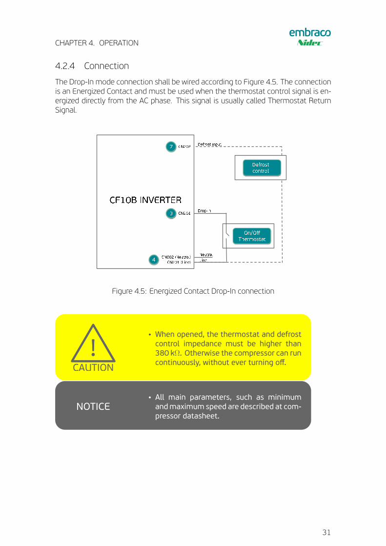
4.2.4 Connection
The Drop-In mode connection shall be wired according to Figure 4.5. The connectionis an Energized Contact and must be used when the thermostat control signal is en-ergized directly from the AC phase. This signal is usually called Thermostat ReturnSignal.
Figure 4.5: Energized Contact Drop-In connection!!
!!
WARNING
!!
NOTICE
CAUTION
• When opened, the thermostat and defrostcontrol impedance must be higher than380 kΩ. Otherwise the compressor can runcontinuously, without ever turning off.
!!
!!
WARNING
!!
NOTICE
CAUTION
• All main parameters, such as minimumandmaximum speed are described at com-pressor datasheet.
31
CHAPTER 4. OPERATION
4.3 Serial control mode
This option is used when an electronic thermostat controls the CF10B Inverter usesa serial communication protocol. Based on Embraco protocol it is possible to definethe compressor speed and check other parameters.
!!
!!
WARNING
!!
NOTICE
CAUTION
• Avoid the use of serial communication withinverter while using the ‘You Control’ inter-face.
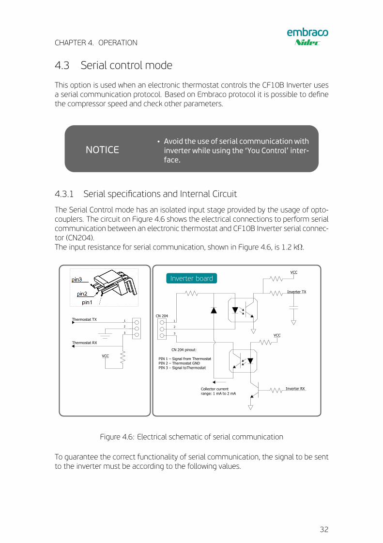
4.3.1 Serial specifications and Internal Circuit
The Serial Control mode has an isolated input stage provided by the usage of opto-couplers. The circuit on Figure 4.6 shows the electrical connections to perform serialcommunication between an electronic thermostat and CF10B Inverter serial connec-tor (CN204).The input resistance for serial communication, shown in Figure 4.6, is 1.2 kΩ.
VCC
CN 203 pinout:
PIN 1 – Signal from ThermostatPIN 2 – Thermostat GND
3
2
1
VCC
Inverter RX
Inverter TX
VCC
CN 204 pinout:
PIN 1 – Signal from ThermostatPIN 2 – Thermostat GNDPIN 3 – Signal toThermostat
Collector currentrange: 1 mA to 2 mA
CN 204
1
3
2
Thermostat TX
Thermostat RX
VCC
Thermostat TX
Inverter board
Figure 4.6: Electrical schematic of serial communication
To guarantee the correct functionality of serial communication, the signal to be sentto the inverter must be according to the following values.
32
CHAPTER 4. OPERATION
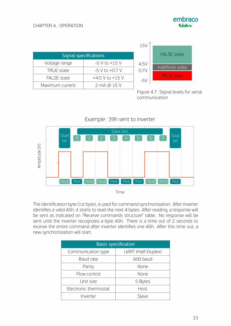
Signal specifications
Voltage range -5 V to +15 V
TRUE state -5 V to +0.7 V
FALSE state +4.5 V to +15 V
Maximum current 2 mA @ 15 V-5V
0.7V
4.5V
15V
TRUE state
Indefinite state
FALSE state
Figure 4.7: Signal levels for serialcommunication
↑
Startbit
Data bitsStopbit
0 1 2 3 4 5 6 7
FALSE TRUE FALSE FALSE TRUE TRUE TRUE FALSE FALSE TRUE
Time
Amplitude
[V]
Example: 39h sent to inverter
The identification byte (1st byte), is used for command synchronization. Aster inverteridentifies a valid A5h, it starts to read the next 4 bytes. Aster reading, a response willbe sent as indicated on ”Receive commands structure” table. No response will besent until the inverter recognizes a byte A5h. There is a time out of 2 seconds toreceive the entire command aster inverter identifies one A5h. Aster this time out, anew synchronization will start.
Basic specification
Communication type UART (Half-Duplex)
Baud rate 600 baud
Parity None
Flow control None
Unit size 5 Bytes
Electronic thermostat Host
Inverter Slave
33
CHAPTER 4. OPERATION
To perform serial communication between a computer (RS-232) and the CF10B In-verter serial connection, please contact Embraco Technical Support to receive instruc-tions.
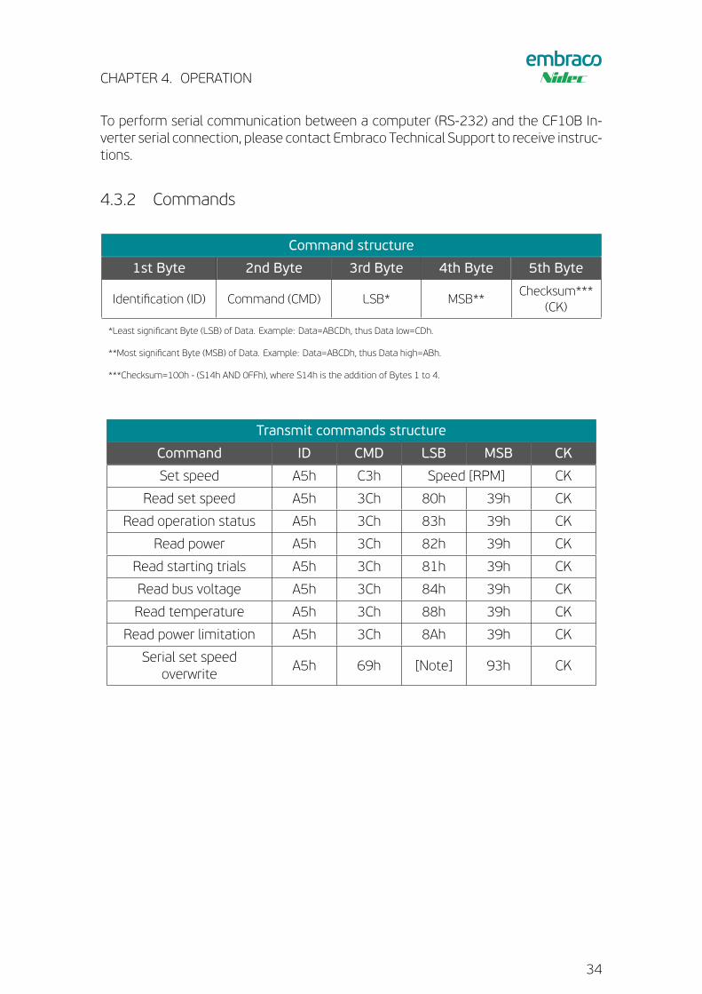
4.3.2 Commands
Command structure
1st Byte 2nd Byte 3rd Byte 4th Byte 5th Byte
Identification (ID) Command (CMD) LSB* MSB**Checksum***
(CK)
*Least significant Byte (LSB) of Data. Example: Data=ABCDh, thus Data low=CDh.
**Most significant Byte (MSB) of Data. Example: Data=ABCDh, thus Data high=ABh.
***Checksum=100h - (S14h AND 0FFh), where S14h is the addition of Bytes 1 to 4.
Transmit commands structure
Command ID CMD LSB MSB CK
Set speed A5h C3h Speed [RPM] CK
Read set speed A5h 3Ch 80h 39h CK
Read operation status A5h 3Ch 83h 39h CK
Read power A5h 3Ch 82h 39h CK
Read starting trials A5h 3Ch 81h 39h CK
Read bus voltage A5h 3Ch 84h 39h CK
Read temperature A5h 3Ch 88h 39h CK
Read power limitation A5h 3Ch 8Ah 39h CK
Serial set speedoverwrite
A5h 69h [Note] 93h CK
34
CHAPTER 4. OPERATION
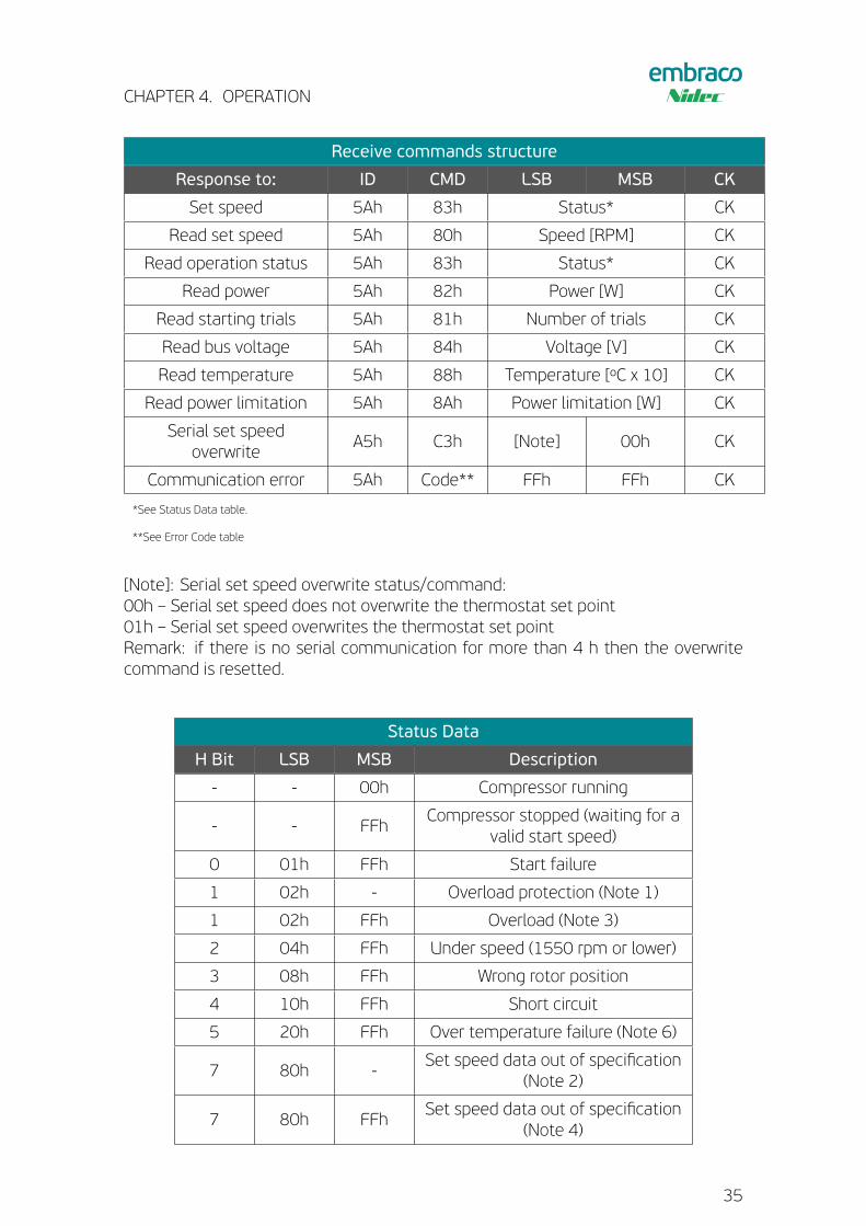
Receive commands structure
Response to: ID CMD LSB MSB CK
Set speed 5Ah 83h Status* CK
Read set speed 5Ah 80h Speed [RPM] CK
Read operation status 5Ah 83h Status* CK
Read power 5Ah 82h Power [W] CK
Read starting trials 5Ah 81h Number of trials CK
Read bus voltage 5Ah 84h Voltage [V] CK
Read temperature 5Ah 88h Temperature [ºC x 10] CK
Read power limitation 5Ah 8Ah Power limitation [W] CK
Serial set speedoverwrite
A5h C3h [Note] 00h CK
Communication error 5Ah Code** FFh FFh CK
*See Status Data table.
**See Error Code table
[Note]: Serial set speed overwrite status/command:00h – Serial set speed does not overwrite the thermostat set point01h – Serial set speed overwrites the thermostat set pointRemark: if there is no serial communication for more than 4 h then the overwritecommand is resetted.
Status Data
H Bit LSB MSB Description
- - 00h Compressor running
- - FFhCompressor stopped (waiting for a
valid start speed)
0 01h FFh Start failure
1 02h - Overload protection (Note 1)
1 02h FFh Overload (Note 3)
2 04h FFh Under speed (1550 rpm or lower)
3 08h FFh Wrong rotor position
4 10h FFh Short circuit
5 20h FFh Over temperature failure (Note 6)
7 80h -Set speed data out of specification
(Note 2)
7 80h FFhSet speed data out of specification
(Note 4)
35
CHAPTER 4. OPERATION
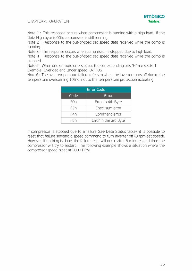
Note 1 : This response occurs when compressor is running with a high load. If theData High byte is 00h, compressor is still running.Note 2 : Response to the out-of-spec set speed data received while the comp isrunning.Note 3 : This response occurs when compressor is stopped due to high load.Note 4 : Response to the out-of-spec set speed data received while the comp isstopped.Note 5 : When one or more errors occur, the corresponding bits “H” are set to 1.Example: Overload and Under speed: 0xFF06Note 6 : The over temperature failure refers to when the inverter turns off due to thetemperature overcoming 105°C, not to the temperature protection actuating.
Error Code
Code Error
F0h Error in 4th Byte
F2h Checksum error
F4h Command error
F8h Error in the 3rd Byte
If compressor is stopped due to a failure (see Data Status table), it is possible toreset that failure sending a speed command to turn inverter off (0 rpm set speed).However, if nothing is done, the failure reset will occur aster 8 minutes and then thecompressor will try to restart. The following example shows a situation where thecompressor speed is set at 2000 RPM.
36
CHAPTER 4. OPERATION
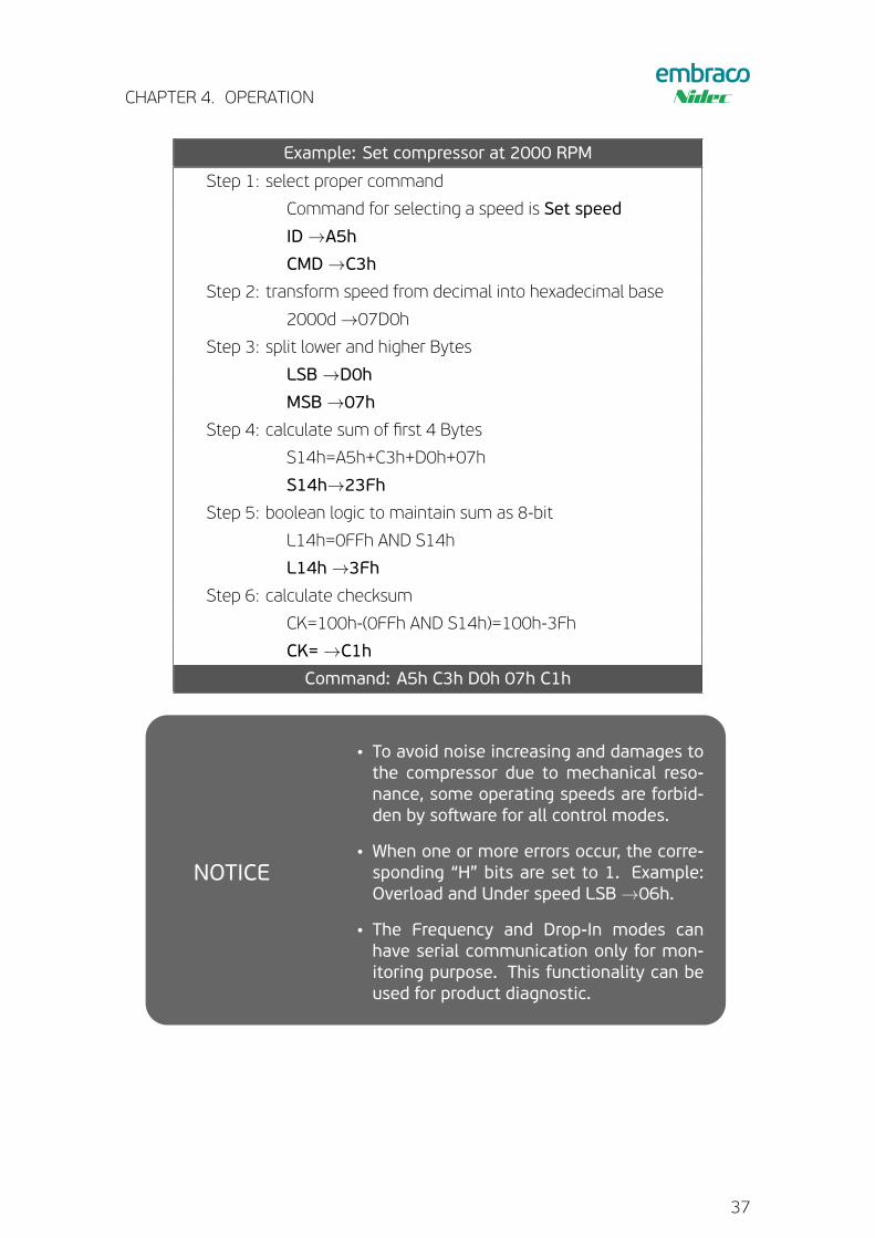
Example: Set compressor at 2000 RPM
Step 1: select proper command
Command for selecting a speed is Set speed
ID→A5h
CMD→C3h
Step 2: transform speed from decimal into hexadecimal base
2000d→07D0h
Step 3: split lower and higher Bytes
LSB→D0h
MSB→07h
Step 4: calculate sum of first 4 Bytes
S14h=A5h+C3h+D0h+07h
S14h→23Fh
Step 5: boolean logic to maintain sum as 8-bit
L14h=0FFh AND S14h
L14h→3Fh
Step 6: calculate checksum
CK=100h-(0FFh AND S14h)=100h-3Fh
CK=→C1h
Command: A5h C3h D0h 07h C1h
!!
!!
WARNING
!!
NOTICE
CAUTION
• To avoid noise increasing and damages tothe compressor due to mechanical reso-nance, some operating speeds are forbid-den by sostware for all control modes.
• When one or more errors occur, the corre-sponding “H” bits are set to 1. Example:Overload and Under speed LSB→06h.
• The Frequency and Drop-In modes canhave serial communication only for mon-itoring purpose. This functionality can beused for product diagnostic.
37
Chapter 5
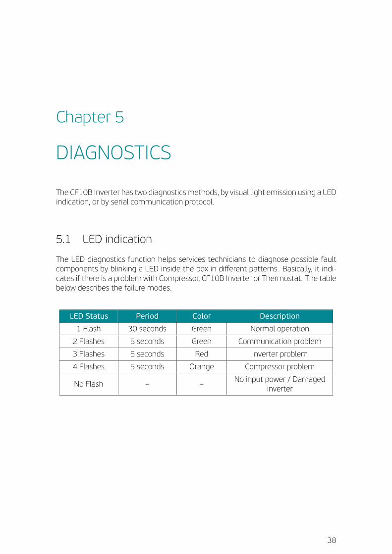
DIAGNOSTICS
The CF10B Inverter has two diagnosticsmethods, by visual light emission using a LEDindication, or by serial communication protocol.
5.1 LED indication
The LED diagnostics function helps services technicians to diagnose possible faultcomponents by blinking a LED inside the box in different patterns. Basically, it indi-cates if there is a problem with Compressor, CF10B Inverter or Thermostat. The tablebelow describes the failure modes.
LED Status Period Color Description
1 Flash 30 seconds Green Normal operation
2 Flashes 5 seconds Green Communication problem
3 Flashes 5 seconds Red Inverter problem
4 Flashes 5 seconds Orange Compressor problem
No Flash – –No input power / Damaged
inverter
38
CHAPTER 5. DIAGNOSTICS
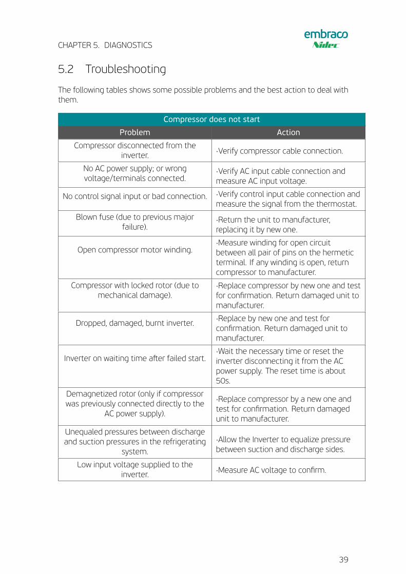
5.2 Troubleshooting
The following tables shows some possible problems and the best action to deal withthem.
Compressor does not start
Problem Action
Compressor disconnected from theinverter. ·Verify compressor cable connection.
No AC power supply; or wrongvoltage/terminals connected.
·Verify AC input cable connection andmeasure AC input voltage.
No control signal input or bad connection. ·Verify control input cable connection andmeasure the signal from the thermostat.
Blown fuse (due to previous majorfailure).
·Return the unit to manufacturer,replacing it by new one.
Open compressor motor winding.·Measure winding for open circuitbetween all pair of pins on the hermeticterminal. If any winding is open, returncompressor to manufacturer.
Compressor with locked rotor (due tomechanical damage).
·Replace compressor by new one and testfor confirmation. Return damaged unit tomanufacturer.
Dropped, damaged, burnt inverter.·Replace by new one and test forconfirmation. Return damaged unit tomanufacturer.
Inverter on waiting time aster failed start.·Wait the necessary time or reset theinverter disconnecting it from the ACpower supply. The reset time is about50s.
Demagnetized rotor (only if compressorwas previously connected directly to the
AC power supply).
·Replace compressor by a new one andtest for confirmation. Return damagedunit to manufacturer.
Unequaled pressures between dischargeand suction pressures in the refrigerating
system.
·Allow the Inverter to equalize pressurebetween suction and discharge sides.
Low input voltage supplied to theinverter. ·Measure AC voltage to confirm.
39
CHAPTER 5. DIAGNOSTICS
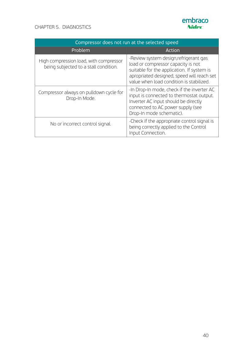
Compressor does not run at the selected speed
Problem Action
High compression load, with compressorbeing subjected to a stall condition.
·Review system design,refrigerant gasload or compressor capacity is notsuitable for the application. If system isapropriated designed, speed will reach setvalue when load condition is stabilized.
Compressor always on pulldown cycle forDrop-In Mode.
·In Drop-In mode, check if the inverter ACinput is connected to thermostat output.Inverter AC input should be directlyconnected to AC power supply (seeDrop-In mode schematic).
No or incorrect control signal.·Check if the appropriate control signal isbeing correctly applied to the ControlInput Connection.
40
DISCLAIMERThe CF10B Inverter is for use exclusively with the Embraco compressors. ALL PROD-UCT, PRODUCT SPECIFICATIONS ANDDATA ARE SUBJECT TO CHANGEWITHOUT NO-TICE TO IMPROVE RELIABILITY, FUNCTION OR DESIGN OR OTHERWISE. Embraco, itsaffiliates, agents, and employees, and all persons acting on its or their behalf (col-lectively, “Embraco”), disclaim any and all liability for any errors, inaccuracies or in-completeness contained in any datasheet or in any other disclosure relating to anyproduct. Embraco makes no warranty, representation or guarantee regarding thesuitability of the products for any particular purpose or the continuing production ofany product. To themaximum extent permitted by applicable law, Embraco disclaims(i) any and all liability arising out of the application or use of any product, (ii) any andall liability, including without limitation special, consequential or incidental damages,and (iii) any and all implied warranties, including warranties of fitness for particularpurpose, non infringement and merchantability. Statements regarding the suitabilityof products for certain types of applications are based on Embraco’s knowledge of typ-ical requirements that are osten placed on Embraco products in generic applications.Such statements are not binding statements about the suitability of products for aparticular application. It is the customer’s responsibility to validate that a particularproduct with the properties described in the product specification is suitable for usein a particular application. Parameters provided in datasheets and/or specificationsmay vary in different applications and performance may vary over time. All operatingparameters, including typical parameters, must be validated for each customer ap-plication by the customer’s technical experts. Product specifications do not expandor otherwise modify Embraco’s terms and conditions of purchase, including but notlimited to the warranty expressed therein. Except as expressly indicated in writing,Embraco products are not designed for use in medical, life-saving, or life-sustainingapplications or for any other application in which the failure of the Embraco productcould result in personal injury or death. Customers using or selling Embraco productsnot expressly indicated for use in such applications do so at their own risk. Please con-tact authorized Embraco personnel to obtain written terms and conditions regardingproducts designed for such applications.No license, express or implied, by estoppel orotherwise, to any intellectual property rights is granted by this document or by anyconduct of Embraco. Product names and markings noted herein may be trademarksof their respective owners. All rights reserved.
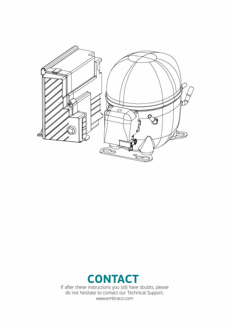
CONTACTIf aster these instructions you still have doubts, pleasedo not hesitate to contact our Technical Support.
www.embraco.com
Related Documents