R.Thiyagarajan Page 1 MAHALAKSHMI ENGINEERING COLLEGE TIRUCHIRAPALLI- 621213. QUESTION BANK DEPARTMENT: EEE SEMESTER – III SUBJECT CODE: EE2201 SUBJECT NAME: Measurements & Instrumentation UNIT II ELECTRICAL AND ELECTRONICS INSTRUMENTS PART-A 1. Give the classification of measuring instruments (MAY 2009) i) Indicating instruments ii)Recording instruments iii) Integrating instruments 2. Differentiate moving coil and moving iron instruments.(DEC 2007, MAY 2011) s.no Moving coil instrument Moving iron instrument 1 The coil of the instrument is moving and connected to the pointer The coil is fixed and produces the necessary magnetic field and an iron piece is moving 2 Suitable only for dc measurements Suitable for both ac and dc measurements 3 The scale is uniform Not uniform 4 The accuracy is high Less accuracy 5 Free from hysteresis and stray magnetic errors. Errors caused due to hysteresis and stray magnetic fields. 6 Low power consumption More power consumption 3. State the advantages of measuring instruments.(MAY 2009)

Welcome message from author
This document is posted to help you gain knowledge. Please leave a comment to let me know what you think about it! Share it to your friends and learn new things together.
Transcript
R.Thiyagarajan Page 1
MAHALAKSHMI
ENGINEERING COLLEGE
TIRUCHIRAPALLI- 621213.
QUESTION BANK
DEPARTMENT: EEE SEMESTER – III
SUBJECT CODE: EE2201 SUBJECT NAME: Measurements & Instrumentation
UNIT II ELECTRICAL AND ELECTRONICS INSTRUMENTS
PART-A
1. Give the classification of measuring instruments (MAY 2009)
i) Indicating instruments
ii)Recording instruments
iii) Integrating instruments
2. Differentiate moving coil and moving iron instruments.(DEC 2007, MAY 2011)
s.no
Moving coil instrument Moving iron instrument
1
The coil of the instrument is moving and connected to the pointer
The coil is fixed and produces the necessary magnetic field and an iron piece is moving
2
Suitable only for dc measurements Suitable for both ac and dc measurements
3
The scale is uniform Not uniform
4
The accuracy is high Less accuracy
5 Free from hysteresis and stray magnetic errors.
Errors caused due to hysteresis and stray magnetic fields.
6
Low power consumption More power consumption
3. State the advantages of measuring instruments.(MAY 2009)

R.Thiyagarajan Page 2
i) Suitable for both ac and dc measurements.
ii) The torque weight ratio is high.
iii) Errors due to friction are less.
iv) The range of instruments can be extended.
4. What is a transfer instrument? (MAY 2007)
The transfer instrument is a instrument which is calibrated with a dc source and used without
any modifications for ac measurements.
5. Why PMMC instruments cannot be used for a.c measurements? (DEC 2006)
Due to moment of inertia of the moving system, the pointer will not follow the rapidly changing
alternating torque and will fail to show correct reading ,hence PMMC instruments not used for
ac measurements.
6. Which meter is useful for only measuring DC quantity? (DEC 2010)
Permanent magnet moving coil meter is used for only measuring DC quantity.
7.What is the difference between analog instruments and digital instruments? (MAY 2008
& 2011)
S.NO Analog instruments
Digital instruments
1. Less accurate More accurate
2. More power consumption less power consumption
3. Less cost Cost is high
4. Less sensitive More sensitive
5. Low input impedance High input impedance

R.Thiyagarajan Page 3
7. Give the classification of DVMS(MAY 2003, 2004 ,2005 ,2009)
i) Non integrating type
ii) Integrating type
Non integrating type
a) Potentiometer type
(1) Servo potentiometric type
(2) Successive approximation type
(3)Null balance type
b) Ramp type
(1)Linear type
(2)Stair case type
The integrating type digital voltmeters are classified
(1) Voltage to frequency converter type
(2) Potentiometric type
(3)Dual slope integrating type
8. Write the function of a instrument transformer. (DEC 2010)
In high voltage and current ac circuits, measurements can not be done using small range
meters; hence specially constructed accurate ratio transformers called instrument transformers
are used.
9. How does one can extend the range of voltmeter and ammeter?(MAY 2007)
The range of ammeter can be extended by connecting low resistance in parallel with the basic
meter which is called shunt resistance.
The range of the voltmeter can be extended by connecting very high resistance in series with
the meter which is called multiplier resistance.

R.Thiyagarajan Page 4
10. What is the need to evaluate phase angle error in instrument transformers?
(DEC 2008)
In the power measurements, it is must that the phase of secondary current is to be displaced by
exactly 180’ from that of primary current for CT. While the phase of secondary voltage is to be
displaced by exact 180 deg, from the primary voltage, for P.T. but actually not so, the error
introduced due to this fact is called phase angle error. Hence it is needed to evaluate.
11. Write the various torques in analog indicating instruments? (DEC 2008,2009)
The three necessary torques are follows
i) Deflecting torque.
ii) Controlling torque.
iii) Damping torque.
12. What is a phase meter? Mention its types. (DEC 2009)
The phase meter is a device which measures the phase difference between the two signals.
Two types:
i) Analog phase meter.
ii) Digital phase meter.
13. List out the methods used for measurement of iron loss in ferro magnetic material (MAY
2010, 2012)
i) Watt meter method.
ii) Bridge method.
iii) Potentiometer method.
iv) Oscillographic method.
14. Why is the ordinary watt meter method not suitable for low power factor circuits? (DEC
2010)
R.Thiyagarajan Page 5
The deflecting torque on the moving system is small as the power factor is low even though the
current and pressure coils are fully excited and the inductance of the pressure coils introduces
considerable error at low power factor.
15. State the two components of iron loss.(MAY 2011)
i) Hysteresis loss.
ii) Eddy current loss.
16. Why do we do Ballistic tests?(DEC 2011)
The ballistic test means DC tests which are used to determine the B-H curve and hysteresis
loop of Ferro magnetic materials.
17. State the purpose of shunt in the ammeter.(MAY 2011)
The shunt is used to bypass the heavier currents so that ammeter carries the safe current and
also used to extend the range of the ammeter.
18. How resistors and diodes are checked using digital multimeters?(DEC 2008)
The range of the resistor is to be noted from the multimeter by varying the values from 200
ohms to 2Mohms, if the reading shows properly then the obtained value are matched with color
coding.
In the DMM select the selector switch to position the diode symbol now connect the positive
probe to anode and negative to cathode thus there was some value obtained, if there was no
values shown or it shows zeros then the diode get defected.
19. List the frequency measuring instruments.(DEC 2004)
i) Weston frequency meter.ii) vibreating reed type frequency meter.
20. what is meant by creeping in energy meter?(MAY 2004)
R.Thiyagarajan Page 6
Without any current through current coil, disc rotates due to the supply voltage excitation in
pressure coil, whish is called creeping.
21. What the two types of moving iron power factor meters?(MAY 2005)
The two types of moving iron power factor meters are
i) Rotating field type.
ii) Alternating field type.
PART B
1) Explain in detail about the construction and working principle of a single phase energy
meter.(DEC 2003, 2006, 2009, MAY 2011, 2012)
Energy meter is an integrating instrument, which measures the quantity of electrical
Energy/power consumed.
Induction type instruments are most common instruments used as energy meter.
Induction type energy meters are commonly used for domestic and industrial
applications.
Generally the energy meters record the energy in KWh.
It works under the principle of induction i.e. on the production of eddy currents in the
moving system interact with each other to produce a driving torque due to which the disc
rotates and record the energy.
The controlling torque is not available in the energy meter, hence the driving torque
produces the rotation of the disc.
To provide the constant speed control there was a braking system is used using a
braking magnet.
There are four major parts of operating mechanism.
i) Driving system
ii) Moving system
iii) Braking system
iv) Registering system
i) Driving system
R.Thiyagarajan Page 7
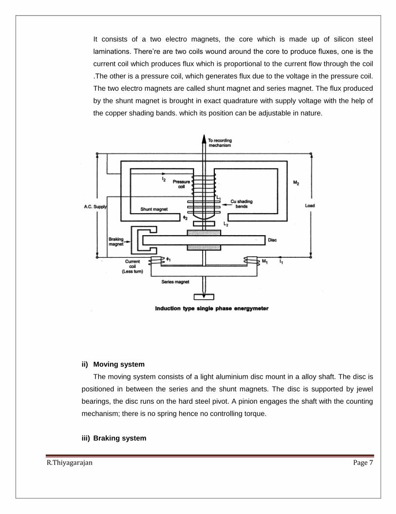
It consists of a two electro magnets, the core which is made up of silicon steel
laminations. There’re are two coils wound around the core to produce fluxes, one is the
current coil which produces flux which is proportional to the current flow through the coil
.The other is a pressure coil, which generates flux due to the voltage in the pressure coil.
The two electro magnets are called shunt magnet and series magnet. The flux produced
by the shunt magnet is brought in exact quadrature with supply voltage with the help of
the copper shading bands. which its position can be adjustable in nature.
ii) Moving system
The moving system consists of a light aluminium disc mount in a alloy shaft. The disc is
positioned in between the series and the shunt magnets. The disc is supported by jewel
bearings, the disc runs on the hard steel pivot. A pinion engages the shaft with the counting
mechanism; there is no spring hence no controlling torque.
iii) Braking system

R.Thiyagarajan Page 8
A permanent magnet is placed near the aluminium disc for braking mechanism, this
magnet produces its own magnetic field the disc moves in the field of its magnet and a
braking torque is obtained. The position of the magnet is adjustable and braking torque
is adjusted by shifting this magnet to different radial positions, this magnet is called
braking magnet.
iv) Registering system
It records continuously a number which is proportional to the revolutions made by the
aluminium disc. A train of reduction gears, the pinion on the disc drives the series of
pointers ,which rotates on the circular dials which is equally divided of equal divisions of
measuring scale of readings.
2) Explain in detail the various adjustments made in energy meter. (DEC 2003, 2009)
To get the perfect and accurate reading the measuring instruments must be adjusted to
eliminate or minimize the errors.
i) Main speed adjustment:
The speed of the energy meter gives the reading of energy consumed. for accurate
reading speed of the instrument also made accurate and proportionate. The speed of the
meter can be adjusted by means of changing the effective radius of the braking magnet.
Moving the braking magnet over the spindle, decreases the effective radius .which
decreases the braking torque . this increase in the speed of the meter. When the
movement of the braking magnet in the outward direction ,increases the radius,
decreasing the speed of the disc. The fine adjustments of the speed can be Achieved by
providing an additional diverter.
ii) Power factor adjustment:
This power factor adjustment is made possible when the flux produced due to current in
the pressure coil lags the applied voltage by an angle of 90degree. But the iron loss and
resistance of winding do not allow the flux to lag by exact 90 Deg,

R.Thiyagarajan Page 9
The fine adjustments can be achieved by the movement of this loop upwards or
downwards and mater can be made to read the power factor accurately.
iii) Friction adjustment:
The friction is one of the problem causing error whish is caused due to the presence of
bearing and the registering mechanism. Due to this the speed of the meter gets affected,
And hence error in the measured energy. To compensate this problem, a metallic loop or
strip is is provided between the central limb of the shunt magnet and the disc. Due to this
additional torque independent of load is produced which acts on the disc in the direction
of the rotation.
iv) Creep adjustment:
Due ton the excitation of supply voltage the meter rotates continuously even though
there was no power consumed, this is called creeping. This may caused due to the over
friction compensation.
To eliminate creeping, two holes are provided at the disc of 180 deg opposite to each
other, when the holes come under the shunt magnet pole, it gets acted upon by a toque
opposite to its direction. It restricts the rotation of disc under no load condition
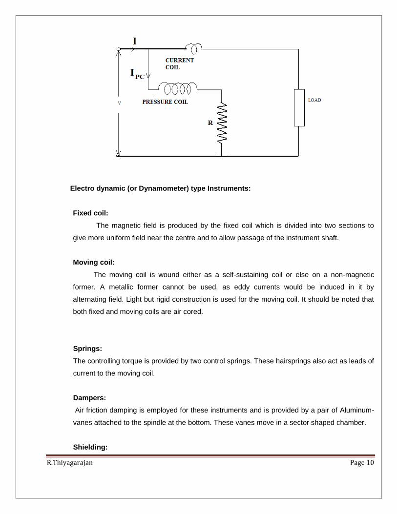
3) Explain single phase dynamometer watt meter in detail.(DEC 2005, 2010, MAY 2004,
2010)
R.Thiyagarajan Page 10
Electro dynamic (or Dynamometer) type Instruments:
Fixed coil:
The magnetic field is produced by the fixed coil which is divided into two sections to
give more uniform field near the centre and to allow passage of the instrument shaft.
Moving coil:
The moving coil is wound either as a self-sustaining coil or else on a non-magnetic
former. A metallic former cannot be used, as eddy currents would be induced in it by
alternating field. Light but rigid construction is used for the moving coil. It should be noted that
both fixed and moving coils are air cored.
Springs:
The controlling torque is provided by two control springs. These hairsprings also act as leads of
current to the moving coil.
Dampers:
Air friction damping is employed for these instruments and is provided by a pair of Aluminum-
vanes attached to the spindle at the bottom. These vanes move in a sector shaped chamber.
Shielding:

R.Thiyagarajan Page 11
Since the magnetic field produced by fixed coils is weaker than that in other types of
instruments, these meters need a special magnetic shielding. Electro-dynamic instruments are
effectively shielded from the effects of external magnetic fields by enclosing the mechanism in
a laminated iron hollow cylinder with closed ends.
Advantages and disadvantages of electro-dynamic instruments
Advantages:
i )Free from hysteresis and eddy current errors.
ii )Applicable to both dc and ac circuits.
iii) Precision grade accuracy for 40 Hz to 500 Hz.
iv)Electro-dynamic voltmeters give accurate r.m.s values of voltage irrespective of waveforms.
Disadvantages:
i) Low torque/weight ratio, hence more frictional errors.
ii) More expensive than PMMC or MI instruments.
iii) Power consumption higher than PMMC but less than MI instruments.
For these reasons, dynamometer ammeters and voltmeters are not in common use (except for
calibration purpose) especially in dc circuits. The most important application of the
dynamometer type instruments used as dynamometer wattmeter.
R.Thiyagarajan Page 12
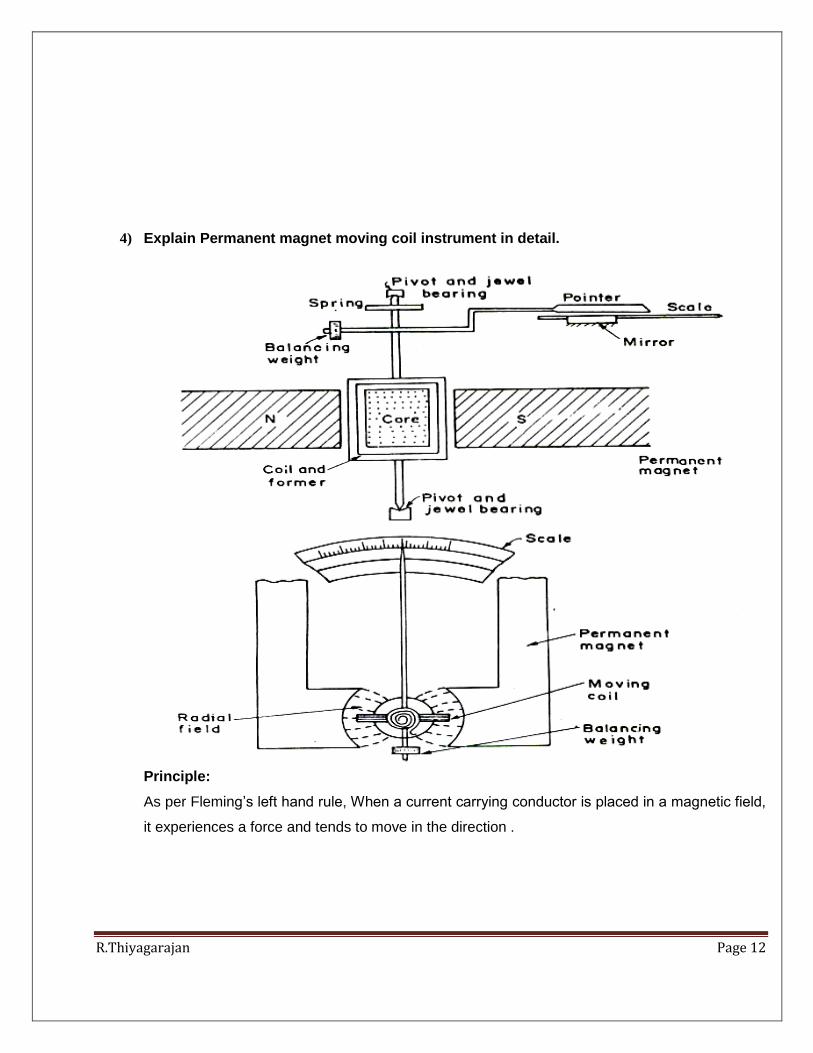
4) Explain Permanent magnet moving coil instrument in detail.
Principle:
As per Fleming’s left hand rule, When a current carrying conductor is placed in a magnetic field,
it experiences a force and tends to move in the direction .
R.Thiyagarajan Page 13
Moving-coil instruments with a permanent-magnet field respond only to direct current. for
Measurement of AC voltage requires a rectifier in the circuit so that the coil deflects in only one
direction.Working principle of PMMC instruments is same as the d’Arsonoval type of
galvanometer the difference being that a direct reading instrument is provided with a pointer and
scale.
Construction:
A coil of thin wire is mounted on frame of an aluminum (spindle) positioned between the U
shaped permanent magnet poles of a which is made up of magnetic alloys like alnico.
The coil is pivoted on the jeweled bearing , the coil is free to rotate. The current is fed to the coil
through spiral springs which are two in numbers. The coil which carries a current, which is to be
measured, moves in a strong magnetic field produced by a permanent magnet and the
measured value shows by a pointer is attached to the spindle.
Working:
When a will current flow through in the coil, it generates a magnetic field which is proportional to
the current in case of an ammeter. In the meter The deflecting torque is produced by the
electromagnetic action of the current in the coil and the magnetic field.
Advantages:
The PMMC consumes less power and has great accuracy.
It has uniformly divided scale and can cover arc of 270 degree.
A high torque to weight ratio in PMMC.
With suitable resistance, It can be modified as ammeter or voltmeter .
efficient damping characteristics and is not affected by stray magnetic field.
No losses produces due to hysteresis.
Disadvantage:
As the reversal of current produces reversal of torque on the coil ,so The moving coil instrument
can only be used on D.C supply

R.Thiyagarajan Page 14
It’s very delicate and sometimes uses ac circuit with a rectifier.
Itis costly as compared to moving coil iron instruments.
due to loss of magnetism of permanent magnet,it can show error .
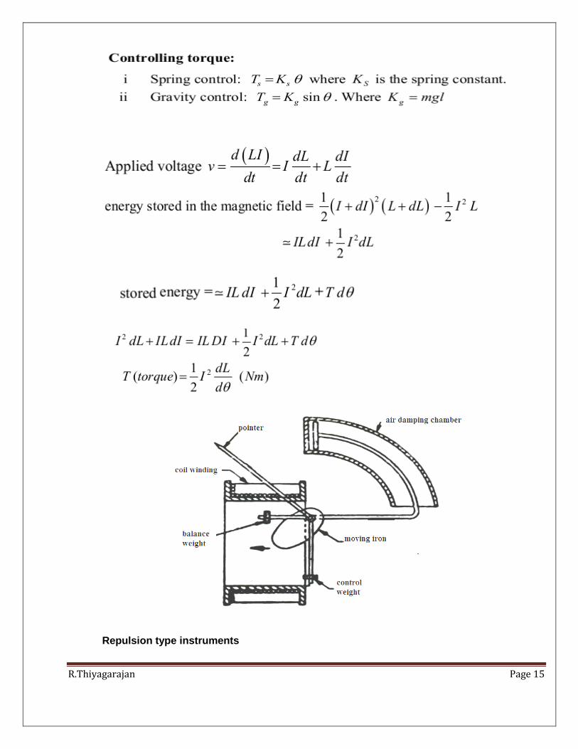
5) Explain in detail- Moving iron instruments and its types.
The deflecting torque in any moving-iron instrument is due to forces on a small
piece of magnetically ‘soft’ iron that is magnetized by a coil carrying the operating
current. In repulsion type moving–iron instrument consists of two cylindrical
soft iron vanes mounted within a fixed current-carrying coil. One iron vane is held fixed
to the coil frame and other is free to rotate, carrying with it the pointer shaft. Two irons lie in the
magnetic field produced by the coil that consists of only few turns if the instrument is an
ammeter or of many turns ifthe instrument is a voltmeter.
Current in the coil induces both vanes to become magnetized and repulsion between the
similarly magnetized vanes produces a proportional rotation. The deflecting torque is
proportional to the square of the current in the coil, making the instrument reading is a true
‘RMS’ quantity Rotation is opposed by a hairspring that produces the restoring torque. Only the
fixed coil carries load current, and it is constructed so as to withstand high transient current.
Moving iron instruments having scales that are nonlinear and somewhat crowded in the lower
range of calibration.Another type of instrument that is usually classed with the attractive types of
instrument.
R.Thiyagarajan Page 15
Repulsion type instruments

R.Thiyagarajan Page 16
6) Explain in detail electrodynamometer type instruments. (MAY 2012)
R.Thiyagarajan Page 17
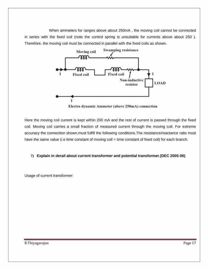
When ammeters for ranges above about 250mA , the moving coil cannot be connected
in series with the fixed coil (note the control spring is unsuitable for currents above about 250 ).
Therefore, the moving coil must be connected in parallel with the fixed coils as shown.
Here the moving coil current is kept within 200 mA and the rest of current is passed through the fixed
coil. Moving coil carries a small fraction of measured current through the moving coil. For extreme
accuracy the connection shown,must fulfill the following conditions.The resistance/reactance ratio must
have the same value (i.e time constant of moving coil = time constant of fixed coil) for each branch.
7) Explain in derail about current transformer and potential transformer.(DEC 2005-06)
Usage of current transformer:
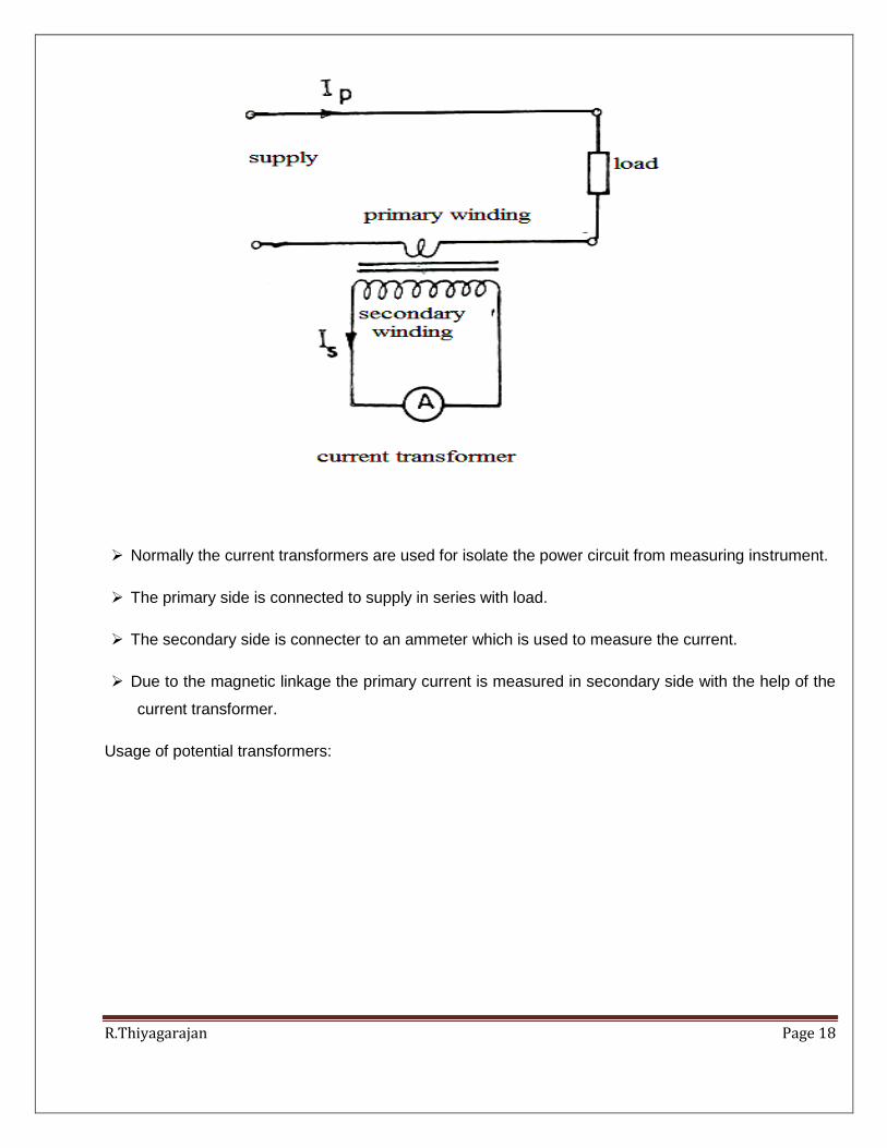
R.Thiyagarajan Page 18
Normally the current transformers are used for isolate the power circuit from measuring instrument.
The primary side is connected to supply in series with load.
The secondary side is connecter to an ammeter which is used to measure the current.
Due to the magnetic linkage the primary current is measured in secondary side with the help of the
current transformer.
Usage of potential transformers:
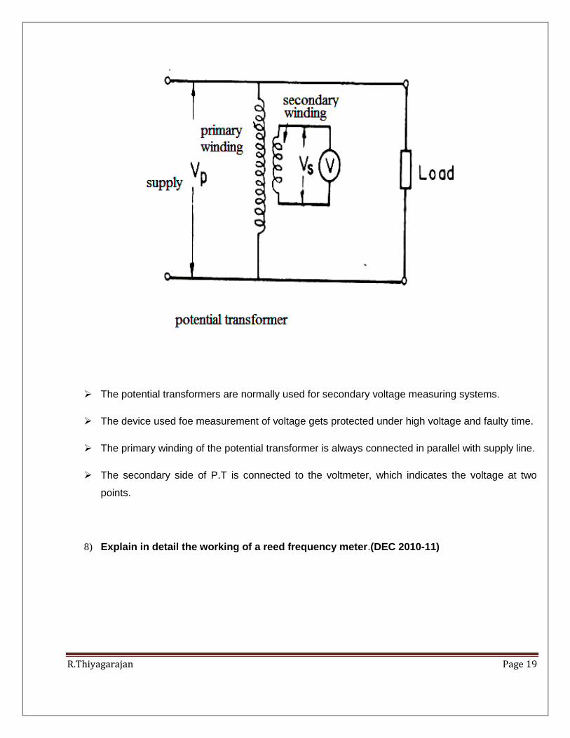
R.Thiyagarajan Page 19
The potential transformers are normally used for secondary voltage measuring systems.
The device used foe measurement of voltage gets protected under high voltage and faulty time.
The primary winding of the potential transformer is always connected in parallel with supply line.
The secondary side of P.T is connected to the voltmeter, which indicates the voltage at two
points.
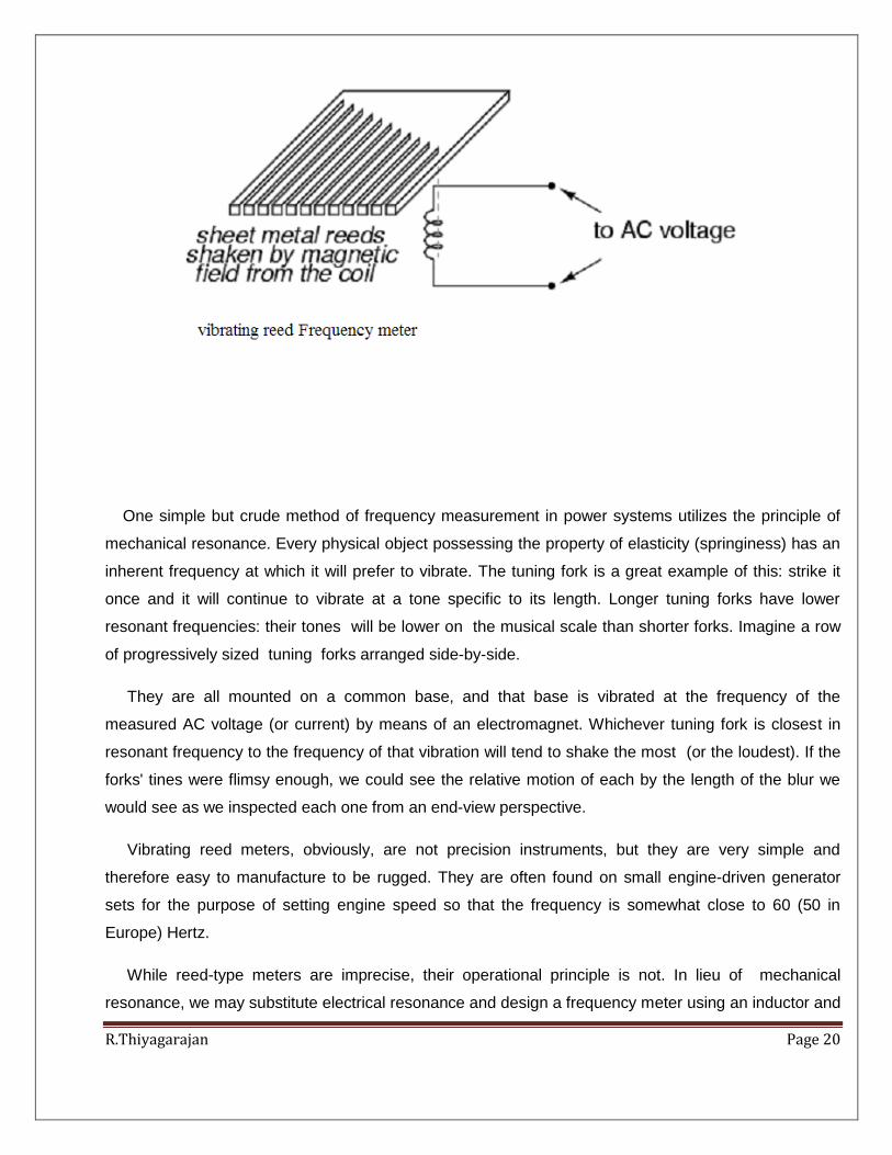
8) Explain in detail the working of a reed frequency meter.(DEC 2010-11)
R.Thiyagarajan Page 20
One simple but crude method of frequency measurement in power systems utilizes the principle of
mechanical resonance. Every physical object possessing the property of elasticity (springiness) has an
inherent frequency at which it will prefer to vibrate. The tuning fork is a great example of this: strike it
once and it will continue to vibrate at a tone specific to its length. Longer tuning forks have lower
resonant frequencies: their tones will be lower on the musical scale than shorter forks. Imagine a row
of progressively sized tuning forks arranged side-by-side.
They are all mounted on a common base, and that base is vibrated at the frequency of the
measured AC voltage (or current) by means of an electromagnet. Whichever tuning fork is closest in
resonant frequency to the frequency of that vibration will tend to shake the most (or the loudest). If the
forks' tines were flimsy enough, we could see the relative motion of each by the length of the blur we
would see as we inspected each one from an end-view perspective.
Vibrating reed meters, obviously, are not precision instruments, but they are very simple and
therefore easy to manufacture to be rugged. They are often found on small engine-driven generator
sets for the purpose of setting engine speed so that the frequency is somewhat close to 60 (50 in
Europe) Hertz.
While reed-type meters are imprecise, their operational principle is not. In lieu of mechanical
resonance, we may substitute electrical resonance and design a frequency meter using an inductor and
R.Thiyagarajan Page 21
capacitor in the form of a tank circuit (parallel inductor and capacitor). See Figure below. One or both
components are made adjustable, and a meter is placed in the circuit to indicate maximum amplitude of
voltage across the two components. The adjustment knob(s) are calibrated to show resonant frequency
for any given setting, and the frequency is read from them after the device has been adjusted for
maximum indication on the meter. Essentially, this is a tunable filter circuit, which is adjusted and then
read in a manner similar to a bridge circuit (which must be balanced for a “null” condition and then
read).
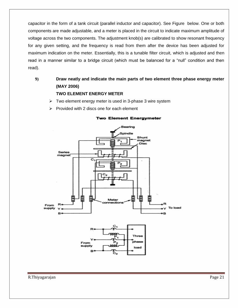
9) Draw neatly and indicate the main parts of two element three phase energy meter
(MAY 2006)
TWO ELEMENT ENERGY METER
Two element energy meter is used in 3-phase 3 wire system
Provided with 2 discs one for each element
R.Thiyagarajan Page 22
Driving torque of both the elements must be exactly equal for equal amounts of power passing
through each. For this an adjustable magnetic shunt is provided on one or both elements and coils are
energized from a 1-PH supply. Pressure coils are connected in parallel and current coils are connected
in series. When energized, torques produced by both elements oppose each other. The magnetic shunt
is adjusted such that the two torques are exactly equal and opposite and therefore there is no rotation
of disc.

R.Thiyagarajan Page 23
R.Thiyagarajan Page 24
Related Documents