Mag-drive Pump Magnochem-Bloc Type Series Booklet

Welcome message from author
This document is posted to help you gain knowledge. Please leave a comment to let me know what you think about it! Share it to your friends and learn new things together.
Transcript

Mag-drive Pump
Magnochem-Bloc
Type Series Booklet

Legal information/Copyright
Type Series Booklet Magnochem-Bloc
All rights reserved. The contents provided herein must neither be distributed, copied, reproduced,edited or processed for any other purpose, nor otherwise transmitted, published or made available toa third party without the manufacturer's express written consent.
Subject to technical modification without prior notice.
© KSB Aktiengesellschaft, Frankenthal 23.07.2014

Contents
Seal-less Pumps ..................................................................................................................................................4
Mag-drive Pumps ............................................................................................................................................................ 4
Magnochem-Bloc ......................................................................................................................................................4
Main applications ................................................................................................................................................ 4
Fluids handled ...................................................................................................................................................... 4
Operating data ....................................................................................................................................................4
Designation .......................................................................................................................................................... 4
Design details ....................................................................................................................................................... 4
Automation .......................................................................................................................................................... 5
Materials ..............................................................................................................................................................5
Coating and preservation ...................................................................................................................................6
Product benefits .................................................................................................................................................. 6
Acceptance tests/Guarantees ..............................................................................................................................6
Pressure and temperature limits ......................................................................................................................... 7
Technical data ...................................................................................................................................................... 8
Selection charts ................................................................................................................................................. 11
Dimensions and connections ............................................................................................................................16
Flange design ..................................................................................................................................................... 25
Scope of supply .................................................................................................................................................. 25
Accessories ......................................................................................................................................................... 26
General assembly drawings ..............................................................................................................................27
Detailed designation .........................................................................................................................................33
Contents
3

Seal-less Pumps
Mag-drive Pumps
Magnochem-Bloc
Main applications
▪ Chemical industry
▪ District heating
▪ Industrial recirculation systems
▪ Air-conditioning systems
▪ Condensate transport
▪ Cooling circuits
▪ Petrochemical industry
▪ Pipelines and tank farms
▪ Refineries
▪ Process engineering
▪ Hot-water heating systems
▪ Sugar industry
Fluids handled
▪ Aggressive fluids
▪ Explosive fluids
▪ Flammable fluids
▪ Toxic fluids
▪ Valuable fluids
▪ Fluids which are injurious to health
▪ Malodorous fluids
Operating data
Operating properties
Characteristic ValueFlow rate Q Up to 625 m³/h (50 Hz)
Up to 754 m³/h (60 Hz)
Characteristic ValueHead H Up to 162 m (50 Hz]
Up to 236 m (60 Hz]Operating temperature t1 -90 °C to +200 °CAmbient temperature t2 -20 °C to +40 °COperating pressure p 40 bar max.
Designation
Example: MACB050-032-2501CCHX1A
Key to the designation
Code DescriptionMACB Type series (full name: Magnochem-Bloc)050 Nominal suction nozzle diameter [mm]032 Nominal discharge nozzle diameter [mm]250 Nominal impeller diameter [mm]1 Hydraulic system, e.g. 1 = low-flow
hydraulic systemC Casing material, e.g. C = stainless steelC Impeller material, e.g. C = stainless steelH Additional code, e.g. H = heatable casingX Special design1 Nominal diameter of magnetic coupling,
e.g. 1 = 85 mmA Effective length of magnetic coupling, e.g.
A = 10 mm
Further information on the designation
(⇨ Page 33)
Design details
Design
▪ Volute casing pump
▪ Horizontal installation
▪ Vertical installation
▪ Close-coupled design
▪ Single-stage
▪ Meets the technical requirements to ISO 5199
▪ Ratings to ISO 2858complemented by pumps of nominal diameters DN 25
Pump casing
▪ Single or double volute, depending on the pump size
▪ Radially split volute casing
▪ Volute casing with integrally cast pump feet
▪ Replaceable casing wear rings
▪ Heatable
▪ Draining facility
Impeller type
▪ Closed radial impeller with multiply curved vanes
▪ Discharge-side sealing clearance reduces axial thrust
Shaft seal
▪ Seal-less, with magnetic coupling
▪ Containment shroud as sealing element
Seal-less PumpsMag-drive Pumps
4 Magnochem-Bloc

Casing cover variants
▪ Internal circulation
▪ Low-boiling fluids
▪ External circulation
▪ Dead-end configuration
In addition:
▪ Flushing connection
▪ Heatable
▪ Draining facility
▪ Internal ring filter or main flow filter
Bearings
Drive-end bearings:
▪ Shaft supported by motor
Pump-end bearings:
▪ Hydrodynamic plain bearings
▪ Product-lubricated
Automation
Automation options:
▪ PumpDrive
▪ PumpMeter
Materials
Overview of available materials
Part No. Description Material Material variantS=standard, O=option
CC CD VV VD EG EC ED YG YC YD DD102 Casing Stainless steel 1.4408/
A743 Gr CF8 MS S - - - - - - - - -
Stainless steel 1.4408 - - S 1) S1) - - - - - - -Duplex stainless steel1.4593/1.4517/A995 GR 1B
- - - - - - - - - - S
Steel GP240GH+N/A216 Gr WCB
- - - - S S S - - - -
1.7706 - - - - - - - S S S -502.01 / 502.02
Casing wear ring Grey cast iron GG/cast iron - - - - O O O O O O -CrNiMo steel O O O O - - - - - - -Duplex steel - - - - - - - - - - OCrNi steel VG 434 - - - - O O O O O O -None S S S S S S S S S S S
411.10 Joint ring CrNi steel/graphite O O O O O O O S S S OThermoplastic S S S S S S S - - - SGylon 3501E O O O O O O O - - - O
230 Impeller Stainless steel 1.4408/A743 GR CF8M
S - S - - S - - S - -
Grey cast iron JL1040/A48CL35 B
- - - - S - - S - - -
Duplex stainless steel1.4593/1.4517/A995 GR 1B
- S - S - - S - - S S
503 Impeller wear ring CrNiMo steel O - O - - O - - O - -Stainless steel 1.4027+QT - - - - O - - O - - -Duplex steel - O - O - - O - - O ONone S S S S S S S S S S S
1) Heatable casing optionally available.
Seal-less PumpsMag-drive Pumps
Magnochem-Bloc 5

Part No. Description Material Material variantS=standard, O=option
CC CD VV VD EG EC ED YG YC YD DD920.95
Impeller nut A4/AISI 316 S S S S S S S S S S -Duplex stainless steel 1.4462/UNS S31803
- - - - - - - - - - S
940.01 Key 1.4571+C/A276 TP316 COND B S S S S S S S S S S -Duplex stainless steel 1.4462/UNS S31803
- - - - - - - - - - S
161 Casing cover Stainless steel 1.4408/A743 GR CF8M
S2) S2) - - - - - - - - -
Stainless steel 1.4408 - - S2) S2) - - - - - - -Duplex stainless steel1.4593/1.4517/A995 GrCD4MCuN
- - - - - - - - - - S2)
Steel GP240GH+N/A216 Gr WCB
- - - - S2) S2) S2) S2) S2) S2) -
391.01 Bearing ring carrier Stainless steel 1.4408/A743 Gr CF8M
S S S S S S S S S S -
Duplex stainless steel 1.4593//1.4517/A995 Gr CD4MCuN
- - - - - - - - - - S
545.21/545.22
Bearing bush SSiC S S S S S S S S S S S
529.21/529.22
Bearing sleeve SSiC S S S S S S S S S S SSiC, DLC-coated O O O O O O O O O O O
386.01/386.02
Thrust bearing ring SSiC S S S S S S S S S S SSiC, DLC-coated O O O O O O O O O O O
818.01 Inner rotor 1.4571-SAMCO S S S S S S S S S S -1.4462-SAMCO - - - - - - - - - - S
23-2.02 Auxiliary impeller CrNiMo St INT S S S S S S S S S S -818.02 Outer rotor ST-SAMCO S S S S S S S S S S S82-15 Containment shroud 1.4571-2.4610 S S S S S S S S S S -
1.4462-2.4610 - - - - - - - - - - SZirconium oxide O O O O O O O O O O O
132.01 Intermediate piece,containment shroud
Stainless steel 1.4408/A743 GR CF8M
S S - - - - - - - - -
Stainless steel 1.4408 - - S S - - - - - - -Steel GP240GH+N/A216 Gr WCB
- - - - S S S S S S -
Duplex stainless steel 1.4593/1.4517/A995 Gr CD4MCuN
- - - - - - - - - - S
210.03 Shaft (plain bearing) Duplex stainless steel 1.4462/UNS S31803
S S S S S S S S S S S
1.4313+QT780/A479 UNS S41500
O O O O O O O O O O -
344 Bearing bracketlantern
Steel GP240GH+N/A216 Gr WCB
S S S S S S S S S S S
Coating and preservation
▪ Coating and preservation to KSB standard
Product benefits
▪ High operating reliability:
– Only static seals are required.
– Containment shroud protected by anti-rub feature
– Self-draining facility of containment shroud
– Pump does not need to be drained before drive unitis fitted/removed.
▪ Broad application range ensured by:
– Product-lubricated plain bearings made of siliconcarbide (DLC coating optionally available)
– Modular design principle for hydraulic system andmagnetic coupling
– Large number of operating modes
– Temperature maintenance and heating facility forcasing and casing cover
Acceptance tests/Guarantees
▪ Materials testing
– Test report 2.2 on request
▪ Final inspection
2) Heatable casing cover optionally available.
Seal-less PumpsMag-drive Pumps
6 Magnochem-Bloc

– Inspection certificate 3.1 to EN 10204 on request
▪ Hydraulic test
The duty point of each pump is guaranteed according toISO 9906/2A.
The following acceptance tests can be performed andcertified at extra charge:
– Performance test to ISO 9906
– NPSH test
▪ Other tests (e.g. vibrations, strength) on request.
▪ Warranty
Warranties are given within the scope of the valid deliveryconditions.
Pressure and temperature limits
Pressure and temperature limits of hydraulic system
0
5
10
15
20
25
30
35
40
45
p [
bar
]
T [°C]
D
EC, V
Y
-100 -50 0 50 100 150 200 250 300 350
Pressure and temperature limits of hydraulic system
The pressure and temperature limits depend on theconfiguration.
Pressure and temperature limits of ASME flanges
C, V
C, V
(ASME 150) E, D(ASME 150)
D
E, D(ASME 300)
0
10
20
30
40
50
60
-100 -50 0 50 100 150 200 250 300 350
p [
bar
]
T[°C]
E
Pressure and temperature limits of ASME flanges3)
Seal-less PumpsMag-drive Pumps
Magnochem-Bloc 7

On models with ASME flanges, the pressure and temperaturelimits are determined by the lowest value given in the diagram"Pressure and temperature limits of hydraulic system" and thediagram "Pressure and temperature limits of ASME flanges".
Technical data
Technical data
Size
Bea
rin
g b
rack
et
Impeller
Cas
ing
typ
e4)
Hea
tab
le c
asin
g
Hea
tab
le c
asin
g c
ove
r
Nominal diameterIm
pel
ler
ou
tlet
wid
th
Free
pas
sag
e
Imp
elle
r in
let
dia
met
er
Imp
elle
r d
iam
eter 85 123 172
Magnetic coupling length [mm]
min max min max min max
max. min. 10 60 10 70 10 100
[mm] [mm] [mm] [mm] [mm] [mm]
040-025-160 CS40 6 5,7 44 169 130 E ✘ ✘ ✘ ✘ -040-025-200 CS40 6 5,7 44 209 160 E - ✘ ✘ ✘ -050-032-125.1 CS40 7 6,0 52 139 114 E - ✘ ✘ ✘ -050-032-160.1 CS40 6 5,4 52 170 138 E ✘ ✘ ✘ ✘ -050-032-200.1 CS40 6 5,3 54 204 138 E ✘ ✘ ✘ ✘ -050-032-250.1 CS50 6 5,2 58 254 220 E ✘ ✘ ✘ ✘ ✘050-032-125 CS40 10 5,7 63 139 110 E ✘ ✘ ✘ ✘ -050-032-160 CS40 9 5,8 63 174 135 E ✘ ✘ ✘ ✘ -050-032-200 CS40 7 6,7 62 209 178 E ✘ ✘ ✘ ✘ -050-032-250 CS50 8 7,1 63 261 212 E ✘ ✘ ✘ ✘ ✘065-040-125 CS40 14 9,6 74 139 110 E - ✘ ✘ ✘ -065-040-160.1 CS40 9 8,5 65 169 130 E - ✘ ✘ ✘ -065-040-160 CS40 13 11,5 70 174 135 E ✘ ✘ ✘ ✘ -065-040-200 CS40 9 8,9 69 209 175 E ✘ ✘ ✘ ✘ -065-040-250.1 CS50 7 6,6 68 260 200 E ✘ ✘ ✘ ✘ ✘065-040-250 CS50 8 8,0 73 260 214 E ✘ ✘ ✘ ✘ ✘065-040-315 CS50 8 7,1 75 326 278 E ✘ ✘ ✘ ✘ ✘080-050-125 CS40 20 11,6 88 142 114 E - ✘ ✘ ✘ -080-050-160 CS40 17 11,6 87 174 135 E ✘ ✘ ✘ ✘ -080-050-200 CS40 14 11,9 83 219 180 E ✘ ✘ ✘ ✘ -080-050-250 CS50 11 10,0 84 260 220 E ✘ ✘ ✘ ✘ ✘080-050-315.1 CS50 8 7,6 85 320 260 E ✘ ✘ ✘ ✘ ✘080-050-315 CS50 10 9,5 86 323 270 E ✘ ✘ ✘ ✘ ✘100-065-125 CS40 26 12,9 99 141 114 E - ✘ ✘ ✘ -100-065-160 CS50 21 12,2 92 174 132 E - ✘ ✘ ✘ ✘100-065-200 CS50 17 13,3 100 219 180 E ✘ ✘ ✘ ✘ ✘100-065-250 CS50 15 14,3 101 260 220 E - ✘ ✘ ✘ ✘100-065-315 CS60 14 13 107 320 270 E - ✘ ✘ ✘ ✘125-080-160 CS50 32 15,1 124 174 122 E - ✘ ✘ ✘ ✘125-080-200 CS50 25 15,2 115 219 180 D ✘ ✘ ✘ ✘ ✘125-080-250 CS50 19 15,8 115 269 220 D ✘ ✘ ✘ ✘ ✘125-080-315 CS60 19 17,8 115 334 281 D ✘ ✘ ✘ ✘ ✘125-080-400 CS60 15 14,3 129 398 330 E ✘ ✘ ✘ ✘ ✘125-100-160 CS50 38 16,4 135 185 155 E - ✘ ✘ ✘ ✘125-100-200 CS50 33 17,9 142 219 179 D - ✘ ✘ ✘ ✘125-100-250 CS60 27 18,8 145 262 216 D ✘ ✘ ✘ ✘ ✘125-100-315 CS60 23 19,9 142 334 280 D - ✘ ✘ ✘ ✘125-100-400 CS60 18 17,1 142 401 329 E - ✘ ✘ ✘ ✘150-125-200 CS60 41 21,1 160 224 162 D - ✘ ✘ ✘ ✘150-125-250 CS60 37 22,4 162 269 218 E - ✘ ✘ ✘ ✘150-125-315 CS60 31 22,6 162 334 280 D ✘ ✘ ✘ ✘ ✘150-125-400 CS60 26 20,9 162 419 330 D ✘ ✘ ✘ ✘ ✘
3) If material Y (ASME 300) is used, the pressure and temperature limits are higher than those stipulated for the hydraulicsystem.
4) E = single volute, D = double volute
Seal-less PumpsMag-drive Pumps
8 Magnochem-Bloc

Size
Bea
rin
g b
rack
et
Impeller
Cas
ing
typ
e4)
Hea
tab
le c
asin
g
Hea
tab
le c
asin
g c
ove
r
Nominal diameter
Imp
elle
r o
utl
et w
idth
Free
pas
sag
e
Imp
elle
r in
let
dia
met
er
Imp
elle
r d
iam
eter 85 123 172
Magnetic coupling length [mm]
min max min max min max
max. min. 10 60 10 70 10 100
[mm] [mm] [mm] [mm] [mm] [mm]
200-150-200 CS60 60 25,2 179 224 158 E - ✘ ✘ ✘ ✘200-150-250 CS60 49 23,0 191 269 220 E ✘ ✘ ✘ ✘ ✘
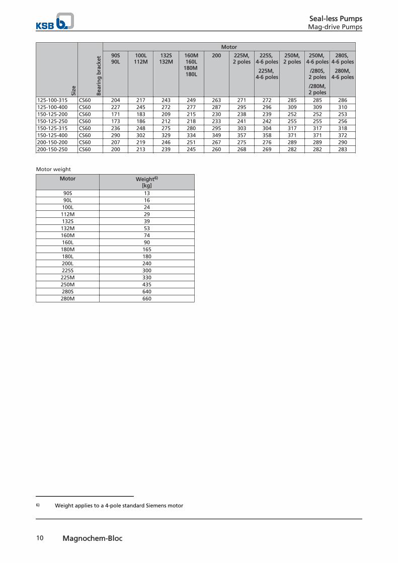
Weight
Weight of pump [kg]5)
Size
Bea
rin
g b
rack
et
Motor
90S90L
100L112M
132S132M
160M160L
180M 180L
200 225M,2 poles
225S, 4-6 poles
225M, 4-6 poles
250M,2 poles
250M, 4-6 poles
/280S,2 poles
/280M,2 poles
280S, 4-6 poles
280M,4-6 poles
040-025-160 CS40 68 79 83 87 - - - - - -040-025-200 CS40 81 92 95 100 - - - - - -050-032-125.1 CS40 65 77 80 84 - - - - - -050-032-160.1 CS40 68 80 83 86 - - - - - -050-032-200.1 CS40 82 93 97 100 - - - - - -050-032-250.1 CS50 125 138 164 170 185 193 194 207 207 208050-032-125 CS40 65 76 80 83 - - - - - -050-032-160 CS40 68 79 82 87 - - - - - -050-032-200 CS40 81 93 96 99 - - - - - -050-032-250 CS50 125 138 164 170 185 193 194 207 207 208065-040-125 CS40 66 78 81 84 - - - - - -065-040-160.1 CS40 72 83 87 91 - - - - - -065-040-160 CS40 70 81 85 89 - - - - - -065-040-200 CS40 83 95 98 104 - - - - - -065-040-250.1 CS50 125 137 164 169 185 193 194 207 207 208065-040-250 CS50 126 139 165 171 186 194 195 208 208 209065-040-315 CS50 161 173 200 205 219 227 228 241 241 242080-050-125 CS40 71 83 86 90 - - - - - -080-050-160 CS40 73 84 88 92 - - - - - -080-050-200 CS40 86 97 101 105 - - - - - -080-050-250 CS50 129 142 168 174 189 197 198 211 211 212080-050-315.1 CS50 160 172 198 204 217 225 226 239 239 240080-050-315 CS50 166 178 205 210 223 231 232 245 245 246100-065-125 CS40 76 88 91 96 - - - - - -100-065-160 CS50 119 133 160 165 179 187 188 201 201 202100-065-200 CS50 119 134 160 166 179 187 188 201 201 202100-065-250 CS50 141 154 180 186 201 209 210 223 223 224100-065-315 CS60 170 183 209 215 230 238 239 252 252 253125-080-160 CS50 122 136 163 168 182 190 191 204 204 205125-080-200 CS50 135 147 174 180 194 202 203 216 216 217125-080-250 CS50 160 172 198 204 219 227 228 241 241 242125-080-315 CS60 195 207 234 239 254 262 263 276 276 277125-080-400 CS60 218 231 258 263 291 299 300 313 313 314125-100-160 CS50 137 151 178 183 197 205 206 219 219 220125-100-200 CS50 148 160 186 192 207 215 216 229 229 230125-100-250 CS60 170 182 208 214 228 236 237 250 250 251
4) E = single volute, D = double volute5) The weight data applies to a pump of max. possible length and with the largest magnetic coupling diameter. The weight
data only applies to unheated models without motor.
Seal-less PumpsMag-drive Pumps
Magnochem-Bloc 9
Size
Bea
rin
g b
rack
et
Motor
90S90L
100L112M
132S132M
160M160L
180M 180L
200 225M,2 poles
225S, 4-6 poles
225M, 4-6 poles
250M,2 poles
250M, 4-6 poles
/280S,2 poles
/280M,2 poles
280S, 4-6 poles
280M,4-6 poles
125-100-315 CS60 204 217 243 249 263 271 272 285 285 286125-100-400 CS60 227 245 272 277 287 295 296 309 309 310150-125-200 CS60 171 183 209 215 230 238 239 252 252 253150-125-250 CS60 173 186 212 218 233 241 242 255 255 256150-125-315 CS60 236 248 275 280 295 303 304 317 317 318150-125-400 CS60 290 302 329 334 349 357 358 371 371 372200-150-200 CS60 207 219 246 251 267 275 276 289 289 290200-150-250 CS60 200 213 239 245 260 268 269 282 282 283
Motor weight
Motor Weight6)
[kg]90S 1390L 16100L 24112M 29132S 39132M 53160M 74160L 90180M 165180L 180200L 240225S 300225M 330250M 435280S 640280M 660
6) Weight applies to a 4-pole standard Siemens motor
Seal-less PumpsMag-drive Pumps
10 Magnochem-Bloc
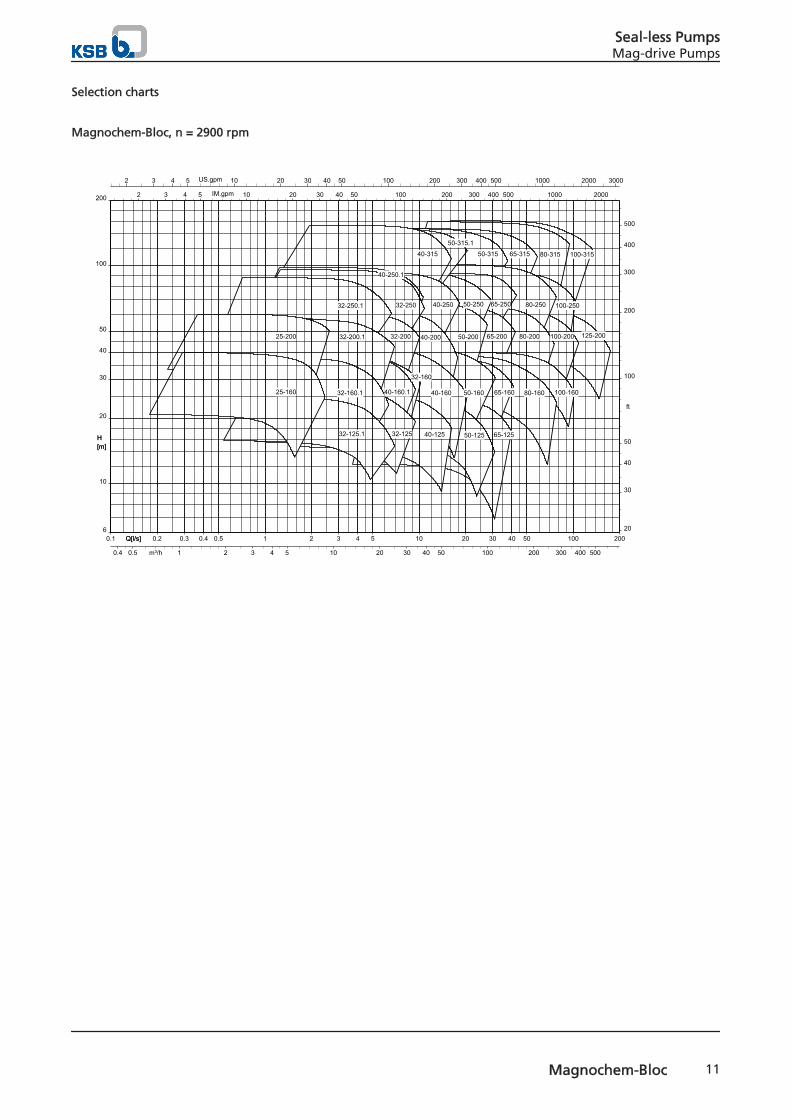
Selection charts
Magnochem-Bloc, n = 2900 rpm
H[m]
Q[l/s]0.1 0.2 0.3 0.4 0.5 1 2 3 4 5 10 20 30 40 50 100 200Q[l/s]
2 3 4 5 10 20 30 40 50 100 200 300 400 500 1000 2000 3000US.gpm
2 3 4 5 10 20 30 40 50 100 200 300 400 500 1000 2000IM.gpm
10
20
30
40
50
100
200
6
H[m]
20
30
40
50
100
200
300
400
500
ft
0.4 0.5 1 2 3 4 5 10 20 30 40 50 100 200 300 400 500m³/h
100-315
125-200
80-31565-31550-315
100-250
100-200
80-250
80-200
65-250
65-200
100-16080-16065-160
65-125
50-250
50-200
50-160
50-125
50-315.1
40-315
40-250
40-200
40-160
40-125
40-250.1
32-250
32-200
32-160
40-160.1
32-125
32-250.1
32-200.1
32-160.1
32-125.1
25-200
25-160
Seal-less PumpsMag-drive Pumps
Magnochem-Bloc 11

Magnochem-Bloc, n = 1450 rpm
H[m]
Q[l/s]0.1 0.2 0.3 0.4 0.5 1 2 3 4 5 10 20 30 40 50 100 200Q[l/s]
2 3 4 5 10 20 30 40 50 100 200 300 400 500 1000 2000 3000US.gpm
2 3 4 5 10 20 30 40 50 100 200 300 400 500 1000 2000IM.gpm
1
2
3
4
5
10
20
30
40
50
70
H[m]
4
5
10
20
30
40
50
100
200
ft
0.4 0.5 1 2 3 4 5 10 20 30 40 50 100 200 300 400 500m³/h
125-400
125-315
100-400
150-250
150-200
100-315
125-250
125-200
80-400
80-315
100-250
100-200
65-31550-315
80-250
80-200
100-160
65-250
50-315.1
65-200
80-16065-160
65-125
50-250
50-200
50-160
50-125
40-315
40-250
40-200
40-250.1
40-160
40-125
32-250
32-200
32-16040-160.1
32-125
32-250.1
32-200.1
32-160.1
32-125.1
25-200
25-160
Seal-less PumpsMag-drive Pumps
12 Magnochem-Bloc

Magnochem-Bloc, n = 960 rpm
H[m]
Q[l/s]0.1 0.2 0.3 0.4 0.5 1 2 3 4 5 10 20 30 40 50 100 200Q[l/s]
2 3 4 5 10 20 30 40 50 100 200 300 400 500 1000 2000 3000US.gpm
2 3 4 5 10 20 30 40 50 100 200 300 400 500 1000 2000IM.gpm
1
2
3
4
5
10
20
30
H[m]
4
5
10
20
30
40
50
ft
0.4 0.5 1 2 3 4 5 10 20 30 40 50 100 200 300 400 500m³/h
125-400
125-315
100-400
150-250
150-200
100-315
125-250
125-200
80-400
80-315
100-250
100-200
65-31550-315
80-250
80-200
100-160
65-250
50-315.1
80-160
65-160
65-125
50-250
50-200
50-160
65-200
50-125
40-315
40-250
40-200
40-250.1
40-160
40-125
32-250
32-200
32-160
40-160.1
32-125
32-250.1
32-200.1
32-160.1
32-125.1
25-200
25-160
Seal-less PumpsMag-drive Pumps
Magnochem-Bloc 13

Magnochem-Bloc, n = 3500 rpm
H[m]
Q[l/s]0.1 0.2 0.3 0.4 0.5 1 2 3 4 5 10 20 30 40 50 100 200 300Q[l/s]
2 3 4 5 10 20 30 40 50 100 200 300 400 500 1000 2000 3000 4000US.gpm
2 3 4 5 10 20 30 40 50 100 200 300 400 500 1000 2000 3000IM.gpm
10
20
30
40
50
100
200
300
9
H[m]
30
40
50
100
200
300
400
500
ft
0.4 0.5 1 2 3 4 5 10 20 30 40 50 100 200 300 400 500 1000m³/h
100-315
125-200
80-31565-31550-315
100-250
100-200
80-250
80-200
65-250
65-200
100-16080-16065-160
65-125
50-250
50-200
50-160
50-125
50-315.140-315
40-250
40-200
40-160
40-125
40-250.1
32-250
32-200
32-16040-160.1
32-125
32-250.1
32-200.1
32-160.1
32-125.1
25-200
25-160
Seal-less PumpsMag-drive Pumps
14 Magnochem-Bloc

Magnochem-Bloc, n = 1750 rpm
H[m]
Q[l/s]0.1 0.2 0.3 0.4 0.5 1 2 3 4 5 10 20 30 40 50 100 200Q[l/s]
2 3 4 5 10 20 30 40 50 100 200 300 400 500 1000 2000 3000US.gpm
2 3 4 5 10 20 30 40 50 100 200 300 400 500 1000 2000IM.gpm
2
3
4
5
10
20
30
40
50
100
H[m]
10
20
30
40
50
100
200
300
ft
0.4 0.5 1 2 3 4 5 10 20 30 40 50 100 200 300 400 500m³/h
125-400
125-315
100-400
150-250
150-200
100-315
125-250
125-200
80-400
80-315
100-250
100-200
65-31550-315
80-250
80-200
100-160
65-250
50-315.1
65-200
80-160
65-160
65-125
50-250
50-200
50-160
50-125
40-315
40-250
40-200
40-250.1
40-160
40-125
32-250
32-200
32-160
40-160.1
32-125
32-250.1
32-200.1
32-160.1
32-125.1
25-200
25-160
Seal-less PumpsMag-drive Pumps
Magnochem-Bloc 15

Magnochem-Bloc, n = 1160 rpm
H[m]
Q[l/s]0.1 0.2 0.3 0.4 0.5 1 2 3 4 5 10 20 30 40 50 100 200Q[l/s]
2 3 4 5 10 20 30 40 50 100 200 300 400 500 1000 2000 3000US.gpm
2 3 4 5 10 20 30 40 50 100 200 300 400 500 1000 2000IM.gpm
1
2
3
4
5
10
20
30
40
50
H[m]
4
5
10
20
30
40
50
100
ft
0.4 0.5 1 2 3 4 5 10 20 30 40 50 100 200 300 400 500m³/h
125-400
125-315
100-400
150-250
150-200
100-315
125-250
125-200
80-400
80-315
100-250
100-200
65-31550-315
80-250
80-200
100-160
65-250
50-315.1
65-200
80-16065-160
65-125
50-250
50-200
50-160
50-125
40-315
40-250
40-200
40-250.1
40-160
40-125
32-250
32-200
32-16040-160.1
32-125
32-250.1
32-200.1
32-160.1
32-125.1
25-200
25-160
Dimensions and connections
Dimensions of the pump set
Dimensions for installation without mounting plate and without support foot
Seal-less PumpsMag-drive Pumps
16 Magnochem-Bloc

Dimensions for installation with mounting plate
Dimensions for installation with site-supplied mounting plate (mounting plate is not included in KSB' scope of supply.)
Seal-less PumpsMag-drive Pumps
Magnochem-Bloc 17

Dimensions for installation with motor feet
Dimensions for vertical installation
Seal-less PumpsMag-drive Pumps
18 Magnochem-Bloc
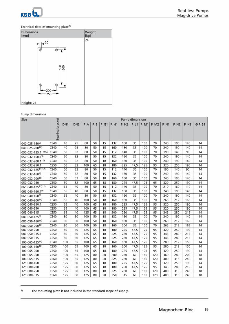
Technical data of mounting plate7)
Dimensions[mm]
Weight[kg]
550
600
200250
20
Height: 25
24
Pump dimensions
Size
Bea
rin
g b
rack
et Pump dimensions
DN1 DN2 P_A P_B P_G1 P_H1 P_H2 P_L1 P_M1 P_M2 P_N1 P_N2 P_N3 Ø P_S1
040-025-1609) CS40 40 25 80 50 15 132 160 35 100 70 240 190 140 14
040-025-20010) CS40 40 25 80 50 15 160 180 35 100 70 240 190 140 14
050-032-125.111)12) CS40 50 32 80 50 15 112 140 35 100 70 190 140 90 14
050-032-160.19) CS40 50 32 80 50 15 132 160 35 100 70 240 190 140 14
050-032-200.110) CS40 50 32 80 50 18 160 180 35 100 70 240 190 140 14050-032-250.1 CS50 50 32 100 65 18 180 225 47,5 125 95 320 250 190 14050-032-12511)12) CS40 50 32 80 50 15 112 140 35 100 70 190 140 90 14
050-032-1609) CS40 50 32 80 50 15 132 160 35 100 70 240 190 140 14
050-032-20010) CS40 50 32 80 50 18 160 180 35 100 70 240 190 140 14050-032-250 CS50 50 32 100 65 18 180 225 47,5 125 95 320 250 190 14065-040-12511)12) CS40 65 40 80 50 15 112 140 35 100 70 210 160 110 14
065-040-160.19) CS40 65 40 80 50 15 132 160 35 100 70 240 190 140 14
065-040-1609) CS40 65 40 80 50 15 132 160 35 100 70 240 190 140 14
065-040-20010) CS40 65 40 100 50 18 160 180 35 100 70 265 212 165 14065-040-250.1 CS50 65 40 100 65 18 180 225 47,5 125 95 320 250 190 14065-040-250 CS50 65 40 100 65 18 180 225 47,5 125 95 320 250 190 14065-040-315 CS50 65 40 125 65 18 200 250 47,5 125 95 345 280 215 14080-050-1259) CS40 80 50 100 50 18 132 160 35 100 70 240 190 140 14
080-050-16010) CS40 80 50 100 50 18 160 180 35 100 70 265 212 165 14
080-050-20010) CS40 80 50 100 50 18 160 200 35 100 70 265 212 165 14080-050-250 CS50 80 50 125 65 18 180 225 47,5 125 95 320 250 190 14080-050-315.1 CS50 80 50 125 65 18 225 280 47,5 125 95 345 280 215 14080-050-315 CS50 80 50 125 65 18 225 280 47,5 125 95 345 280 215 14100-065-12510) CS40 100 65 100 65 18 160 180 47,5 125 95 280 212 150 14
100-065-16010) CS50 100 65 100 65 18 160 200 47,5 125 95 280 212 150 14100-065-200 CS50 100 65 100 65 18 180 225 47,5 125 95 320 250 190 14100-065-250 CS50 100 65 125 80 20 200 250 60 160 120 360 280 200 18100-065-315 CS60 100 65 125 80 20 225 280 60 160 120 400 315 240 18125-080-160 CS50 125 80 125 65 18 180 225 47,5 125 95 320 250 190 14125-080-200 CS50 125 80 125 65 18 180 250 47,5 125 95 345 280 215 14125-080-250 CS50 125 80 125 80 18 225 280 60 160 120 400 315 240 18125-080-315 CS60 125 80 125 80 20 250 315 60 160 120 400 315 240 18
7) The mounting plate is not included in the standard scope of supply.
Seal-less PumpsMag-drive Pumps
Magnochem-Bloc 19

Size
Bea
rin
g b
rack
et Pump dimensions
DN1 DN2 P_A P_B P_G1 P_H1 P_H2 P_L1 P_M1 P_M2 P_N1 P_N2 P_N3 Ø P_S1
125-080-400 CS60 125 80 125 80 20 280 355 60 160 120 435 355 275 18125-100-160 CS50 125 100 125 80 18 200 280 60 160 120 360 280 200 19125-100-200 CS50 125 100 125 80 18 200 280 60 160 120 360 280 200 18125-100-250 CS60 125 100 140 80 18 225 280 60 160 120 400 315 240 18125-100-315 CS60 125 100 140 80 18 250 315 60 160 120 400 315 240 18125-100-400 CS60 125 100 140 100 20 280 355 75 200 150 500 400 300 23150-125-200 CS60 150 125 140 80 20 250 315 60 160 120 400 315 240 19150-125-250 CS60 150 125 140 80 20 250 355 60 160 120 400 315 240 18150-125-315 CS60 150 125 140 100 20 280 355 75 200 150 500 400 300 23150-125-400 CS60 150 125 140 100 20 315 400 75 200 150 500 400 300 23200-150-200 CS60 200 150 180 100 20 280 400 75 200 150 550 450 350 24200-150-250 CS60 200 150 160 100 20 280 375 75 200 150 500 400 300 23
Pump dimensions
Size
Bea
rin
g b
rack
et
Motor size8)
90S90L
100L112M
132S132M
160M160L180M180L
200 225M, 2 poles225S, 4-6 poles225M, 4-6 poles
250M, 2 poles250M, 4-6 poles
280S, 2 poles280M, 2 poles280S, 4-6 poles280M, 4-6 poles
P_F1
040-025-1609) CS40 314 319 345 379 - - -
040-025-20010) CS40 314 319 345 379 - - -
050-032-125.111)12) CS40 314 319 345 379 - - -
050-032-160.19) CS40 314 319 345 379 - - -
050-032-200.110) CS40 314 319 345 379 - - -050-032-250.1 CS50 399 404 430 464 504 524 534050-032-12511)12) CS40 314 319 345 379 - - -
050-032-1609) CS40 314 319 345 379 - - -
050-032-20010) CS40 314 319 345 379 - - -050-032-250 CS50 399 404 430 464 504 524 534065-040-12511)12) CS40 314 319 345 379 - - -
065-040-160.19) CS40 314 319 345 379 - - -
065-040-1609) CS40 314 319 345 379 - - -
065-040-20010) CS40 314 319 345 379 - - -065-040-250.1 CS50 399 404 430 464 504 524 534065-040-250 CS50 399 404 430 464 504 524 534065-040-315 CS50 399 404 430 464 504 524 534080-050-1259) CS40 314 319 345 379 - - -
080-050-16010) CS40 314 319 345 379 - - -
080-050-20010) CS40 314 319 345 379 - - -080-050-250 CS50 399 404 430 464 504 524 534080-050-315.1 CS50 399 404 430 464 504 524 534080-050-315 CS50 399 404 430 464 504 524 534100-065-12510) CS40 314 319 345 379 - - -
100-065-16010) CS50 399 404 430 464 504 524 534100-065-200 CS50 399 404 430 464 504 524 534100-065-250 CS50 399 404 430 464 504 524 534100-065-315 CS60 399 404 430 464 504 524 534
8) From motor size 200, always with motor foot9) A mounting plate is required for motor 132.10) A mounting plate is required for motors 160 and 180.11) A mounting plate is required for motors 100 and 112.12) A mounting plate with a height of 38 mm is required for motor 132. (Not included in the scope of supply)
Seal-less PumpsMag-drive Pumps
20 Magnochem-Bloc

Size
Bea
rin
g b
rack
et
Motor size8)
90S90L
100L112M
132S132M
160M160L180M180L
200 225M, 2 poles225S, 4-6 poles225M, 4-6 poles
250M, 2 poles250M, 4-6 poles
280S, 2 poles280M, 2 poles280S, 4-6 poles280M, 4-6 poles
P_F1125-080-160 CS50 399 404 430 464 504 524 534125-080-200 CS50 399 404 430 464 504 524 534125-080-250 CS50 399 404 430 464 504 524 534125-080-315 CS60 399 404 430 464 504 524 534125-080-400 CS60 399 404 430 464 504 524 534125-100-160 CS50 399 404 430 464 504 524 534125-100-200 CS50 399 404 430 464 504 524 534125-100-250 CS60 399 404 430 464 504 524 534125-100-315 CS60 399 404 430 464 504 524 534125-100-400 CS60 399 404 430 464 504 524 534150-125-200 CS60 399 404 430 464 504 524 534150-125-250 CS60 399 404 430 464 504 524 534150-125-315 CS60 399 404 430 464 504 524 534150-125-400 CS60 399 404 430 464 504 524 534200-150-200 CS60 399 404 430 464 504 524 534200-150-250 CS60 399 404 430 464 504 524 534
Motor dimensions
Motor dimensions
Des
ign
atio
n
90S
90L
100L
112M
132S
132M
160M
160L
180M
180L
200L
2 poles 4 poles
225M
250M
280S
280M
225M
225S
250M
280S
280M
M_LB13) 282 308 382 371 413 441 546 552 610 610 669 755 817 925 980 725 695 817 925 980
M_DA13) 190 190 213 234 266 298 325 325 370 370 422 468 520 575 575 468 460 520 575 575M_DFL 200 200 250 250 300 300 350 350 350 350 400 450 550 550 550 450 450 550 550 550A_L14) - - - - - - - - - - 637 673 702 724 724 673 673 702 724 724M_H1 - - - - - - - - - - 200 225 250 280 280 225 225 250 280 280M_A - - - - - - - - - - 318 356 406 457 457 356 356 406 457 457M_AA13) - - - - - - - - - - 85 100 100 100 100 100 100 100 100 100
M_AB 13) - - - - - - - - - - 400 450 506 557 557 450 450 506 557 557M_B - - - - - - - - - - 305 311 349 368 419 311 286 349 368 419M_BB13) - - - - - - - - - - 388 410 425 480 530 410 385 425 480 530M_BK - - - - - - - - - - 19 19 24 24 24 19 19 24 24 24M_HA13) - - - - - - - - - - 30 35 40 40 40 35 35 40 40 40
8) From motor size 200, always with motor foot13) The figures indicated refer to the maximum dimensions.14) The dimension applies to a motor combined with a CS50 or CS60 bearing bracket.
Seal-less PumpsMag-drive Pumps
Magnochem-Bloc 21

Dimensions of pump with support foot
Dimensions for installation with support foot
Dimensions for installation with support foot and mounting plate
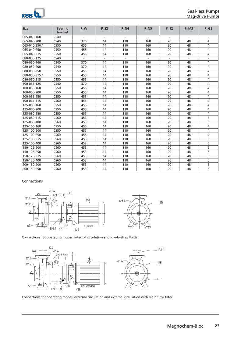
Dimensions of pump with support foot
Size Bearingbracket
P_W P_S2 P_N4 P_N5 P_12 P_M3 P_G2
040-025-160 CS40 - - - - - - -040-025-200 CS40 370 14 110 160 20 48 4050-032-125.1 CS40 - - - - - - -050-032-160.1 CS40 - - - - - - -050-032-200.1 CS40 370 14 110 160 20 48 4050-032-250.1 CS50 455 14 110 160 20 48 4050-032-125 CS40 - - - - - - -050-032-160 CS40 - - - - - - -050-032-200 CS40 370 14 110 160 20 48 4050-032-250 CS50 455 14 110 160 20 48 4065-040-125 CS40 - - - - - - -065-040-160.1 CS40 - - - - - - -
Seal-less PumpsMag-drive Pumps
22 Magnochem-Bloc
Size Bearingbracket
P_W P_S2 P_N4 P_N5 P_12 P_M3 P_G2
065-040-160 CS40 - - - - - - -065-040-200 CS40 370 14 110 160 20 48 4065-040-250.1 CS50 455 14 110 160 20 48 4065-040-250 CS50 455 14 110 160 20 48 4065-040-315 CS50 455 14 110 160 20 48 4080-050-125 CS40 - - - - - - -080-050-160 CS40 370 14 110 160 20 48 4080-050-200 CS40 370 14 110 160 20 48 4080-050-250 CS50 455 14 110 160 20 48 4080-050-315.1 CS50 455 14 110 160 20 48 4080-050-315 CS50 455 14 110 160 20 48 4100-065-125 CS40 370 14 110 160 20 48 4100-065-160 CS50 455 14 110 160 20 48 4100-065-200 CS50 455 14 110 160 20 48 4100-065-250 CS50 455 14 110 160 20 48 4100-065-315 CS60 455 14 110 160 20 48 4125-080-160 CS50 455 14 110 160 20 48 4125-080-200 CS50 455 14 110 160 20 48 4125-080-250 CS50 455 14 110 160 20 48 4125-080-315 CS60 453 14 110 160 20 48 6125-080-400 CS60 453 14 110 160 20 48 6125-100-160 CS50 455 14 110 160 20 48 4125-100-200 CS50 455 14 110 160 20 48 4125-100-250 CS60 455 14 110 160 20 48 4125-100-315 CS60 453 14 110 160 20 48 6125-100-400 CS60 453 14 110 160 20 48 6150-125-200 CS60 453 14 110 160 20 48 6150-125-250 CS60 453 14 110 160 20 48 6150-125-315 CS60 453 14 110 160 20 48 6150-125-400 CS60 453 14 110 160 20 48 6200-150-200 CS60 453 14 110 160 20 48 6200-150-250 CS60 453 14 110 160 20 48 6
Connections
Connections for operating modes: internal circulation and low-boiling fluids
Connections for operating modes: external circulation and external circulation with main flow filter
Seal-less PumpsMag-drive Pumps
Magnochem-Bloc 23

Connections for dead-end configuration operating mode
Connections for heating15)
Connections for heat exchanger
Connections at the volute casing
Connection Discharge nozzle Description
≤ DN 50 DN 65 - DN 80 ≥ DN 1001M.1 G1/4 G3/8 G1/2 Pressure gauge1M.2 G1/4 G3/8 G1/2 Pressure gauge6B16) G1/4 G3/8 G1/2 Fluid drain (volute casing)12A G1/4 G3/8 G1/2 Circulation liquid OUT16B.1 G1/4 Condensate drain (volute casing)19A.1 G3/8 Heating liquid OUT (volute casing)19E.1 G3/8 Heating liquid IN (volute casing)
15) Only possible for operating modes: internal circulation, low-boiling fluids and dead-end configuration16) Design with DN 15 flange if drain line is provided.
Seal-less PumpsMag-drive Pumps
24 Magnochem-Bloc

Connections for casing cover 161, bearing bracket lantern 344, intermediate piece 132.03, main flow filter
Connection Bearing bracket CS40/CS50/CS60 with MD 85/123/172
Description
4M.3 G1/4 Temperature monitoring of containmentshroud, PT 100
4M.4 G1/4 Temperature monitoring of containmentshroud, thermocouple
6B.1 G1/4 Containment shroud drain8B G1/4 Bearing bracket lantern drain8M.1 G1/4 Leakage monitoring (gas, vapour)8M.2 G3/4 Leakage monitoring (liquid)10A G1/4 Barrier fluid OUT10E G1/4 Barrier fluid IN11E G1/4 Flushing liquid, containment shroud IN12A.1 G1/4 Main flow filter OUT12E G1/4 Circulation liquid IN13B G1/4 Oil drain13D Diameter 20 Vent plug19A.2 G3/8 Heating liquid OUT (casing cover)19E.2 G3/8 Heating liquid IN (casing cover)638 Rp 1/4 Constant level oiler
Connections for heat exchanger
Connection Heat exchanger size Connection Description7A 76 G 3/8 Cooling liquid OUT
115 G 3/4152 G 1
7E 76 G 3/8 Cooling liquid IN115 G 3/4152 G 1
5B 76 G 3/4 Venting115152
10H 76 G 1 Monitoring and check115152
Flange design
Overview of available flange designs
Material Standard Pressure classC EN 1092-1 PN16
Drilled to ASME B16.5 Class 150V EN 1092-1 PN16
Drilled to ASME B16.5 Class 150E EN 1092-1 PN16
Drilled to ASME B16.5 Class 150/Class 300E EN 1092-1 PN25
Drilled to ASME B16.5 Class 150/Class 300Y EN 1092-1 PN40
Drilled to ASME B16.5 Class 300D EN 1092-1 PN16
Drilled to ASME B16.5 Class 150/Class 300D EN 1092-1 PN25
Drilled to ASME B16.5 Class 150/Class 300Heatable casing EN 1092-1 PN16
Drilled to ASME B16.5 Class 150
Scope of supply
Depending on the model, the following items are included inthe scope of supply:
▪ Pump
▪ Mounting plate
▪ Mounting plate adjusting elements for installationwithout foundation
Seal-less PumpsMag-drive Pumps
Magnochem-Bloc 25
Special accessories
▪ As required
Accessories
▪ Temperature monitoring (metal containment shroud)
– PT100
– Mineral-insulated thermocouple
▪ Fill level monitoring to protect against dry running
– Liquiphant level transmitter
▪ Monitoring for containment shroud leakage
– Liquiphant level transmitter
– Contact pressure gauge
– Pressure switch
– Pressure transducer
▪ Monitoring of pump power to detect dry running and/orasynchronous operation of the magnetic coupling and toprotect against overload operation
– Motor load monitor
Electronic analysis equipment as well as additional componentsfor operation in potentially explosive atmospheres can also beordered from KSB.
Seal-less PumpsMag-drive Pumps
26 Magnochem-Bloc
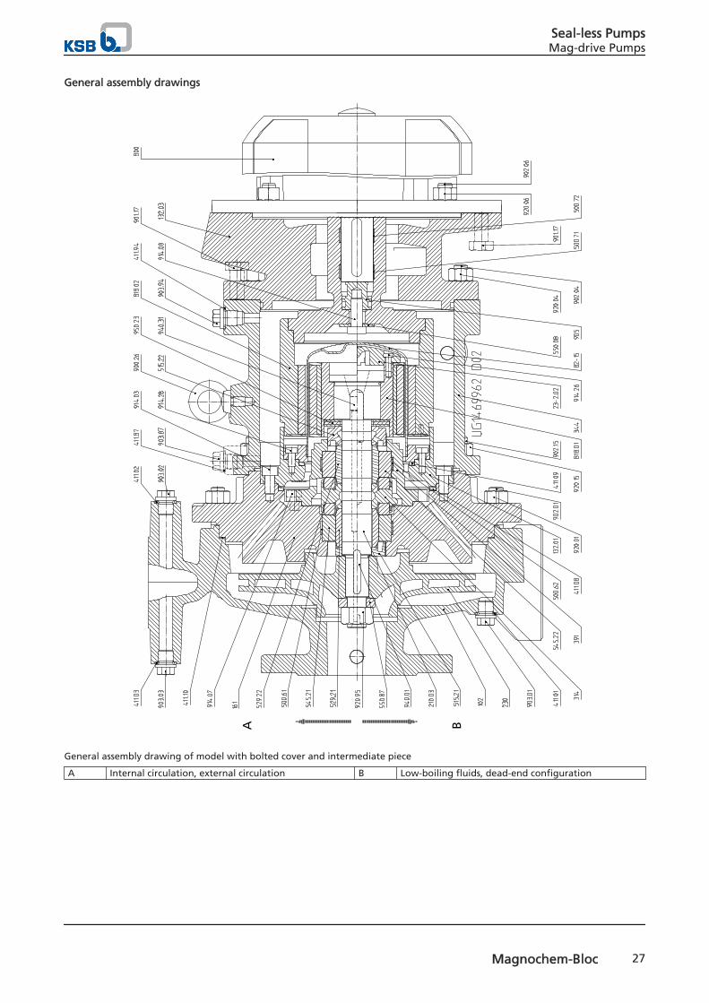
General assembly drawings
A B
General assembly drawing of model with bolted cover and intermediate piece
A Internal circulation, external circulation B Low-boiling fluids, dead-end configuration
Seal-less PumpsMag-drive Pumps
Magnochem-Bloc 27

Discharge cover fastening at pump casing on designs with bolted cover
Seal-less PumpsMag-drive Pumps
28 Magnochem-Bloc

A B
General assembly drawing of model with clamped cover and without intermediate piece
A Internal circulation, external circulation B Low-boiling fluids, dead-end configuration
Seal-less PumpsMag-drive Pumps
Magnochem-Bloc 29

Discharge cover fastening at pump casing on designs with clamped cover
Support foot fastening for motors 160 and 180
A
Model with volute casing and ring filter, heating chamber,casing and impeller wear rings
A Heating chamber
Seal-less PumpsMag-drive Pumps
30 Magnochem-Bloc

Design with ceramic containment shroud
List of components
Part No. Comprising Description102 102 Volute casing
411.0117) /.0217)/.0317) /.0417) Joint ring
502.0117) Casing wear ring902.01 Stud903.0117) /.0217) /.0317) /.0417) Screw plug920.01 Hexagon nut
132.03 132.03 Intermediate piece161 161 Casing cover502.0217) 502.0217) Casing wear ring183 18317) Support foot210.03 210.03 Shaft
550.87 Disc920.95 Nut940.01/.31 Key
230 230 Impeller503.0117) /.0217) Impeller wear ring
23-2.02 23-2.0217) Auxiliary impeller
914.2617) Hexagon socket head cap screw310 310 Plain bearing assembly
500.61 Locking element500.62 Locking element515.21 Taper lock ring515.22 Taper lock ring529.21 Plain bearing sleeve529.22 Plain bearing sleeve
17) Not on all versions.
Seal-less PumpsMag-drive Pumps
Magnochem-Bloc 31

Part No. Comprising Description545.21 Plain bearing bush545.22 Plain bearing bush
314 314 Thrust bearing344 344 Bearing bracket lantern391 391 Bearing ring carrier411.08 411.08 Joint ring411.09 411.09 Joint ring411.10 411.10 Joint ring411.22 /.87 /.94 411.22 /.87 /.94 Joint ring500.71 /.72 500.71 /.72 Locking elements509.02 509.02 Intermediate ring550.08 550.08 Disc800 800 Motor818.01 818.01 Inner rotor818.02 818.02 Outer rotor82-15 82-15 Containment shroud
132.01 Containment shroud intermediate piece72318) Containment shroud flange914.03 Hexagon socket head cap screw914.28 Hexagon socket head cap screw
900.26 900.26 Eyebolt901.04 901.0417) Hexagon head bolt901.17 901.17 Hexagon head bolt901.30 901.30 Hexagon head bolt901.31 901.31 Hexagon head bolt901.74 901.74 Hexagon head bolt902.04 902.04 Stud902.06 902.06 Stud902.15 902.15 Stud903.22 /.87 /.94 903.22 /.87 /.94 Screw plug905 905 Threaded connecting element914.07 914.07 Hexagon socket head cap screw914.08 914.08 Hexagon socket head cap screw920.04 920.04 Nut920.06 920.06 Nut920.15 920.15 Nut950.23 950.23 Disc springCasing cover design with ring filter745.04 745.04 Filter932.06 932.06 Circlip
Plain bearings arrangement
Overview of plain bearings arrangement
Hydraulic system Bearing bracket Nominal diameter of magnetic coupling
85 123 172
119) 219) 319)
040-25-160 CS40 A31 A31 -040-25-200 CS40 A31 A31 -050-32-125.1 CS40 A31 A31 -050-32-160.1 CS40 A31 A31 -050-32-200.1 CS40 A31 A31 -050-32-250.1 CS50 B31 B31 A31050-32-125 CS40 A31 A31 -050-32-160 CS40 A31 A31 -050-32-200 CS40 A31 A31 -050-32-250 CS50 B31 B31 A31065-40-125 CS40 A31 A31 -065-40-160.1 CS40 A31 A31 -
18) For pump sets with ceramic containment shroud only19) Nominal diameter of magnetic coupling as per name plate
Seal-less PumpsMag-drive Pumps
32 Magnochem-Bloc

Hydraulic system Bearing bracket Nominal diameter of magnetic coupling
85 123 172
119) 219) 319)
065-40-160 CS40 A31 A31 -065-40-200 CS40 A31 A31 -065-40-250.1 CS50 B31 B31 A31065-40-250 CS50 B31 B31 A31065-40-315 CS50 B31 B31 A31080-50-125 CS40 A31 A31 -080-50-160 CS40 A31 A31 -080-50-200 CS40 A31 A31 -080-50-250 CS50 B31 B31 A31080-50-315.1 CS50 B31 B31 A31080-50-315 CS50 B31 B31 A31100-65-125 CS40 A31 A31 -100-65-160 CS50 B31 B31 A31100-65-200 CS50 B31 B31 A31100-65-250 CS50 B31 B31 A31100-65-315 CS60 B31 B31 A31125-80-160 CS50 B31 B31 A31125-80-200 CS50 B31 B31 A31125-80-250 CS50 B31 B31 A31125-80-315 CS60 B31 B31 A31125-80-400 CS60 B31 B31 A31125-100-160 CS50 B31 B31 A31125-100-200 CS50 B31 B31 A31125-100-250 CS60 B31 B31 A31125-100-315 CS60 B31 B31 A31125-100-400 CS60 B31 B31 A31150-125-200 CS60 B31 B31 A31150-125-250 CS60 B31 B31 A31150-125-315 CS60 B31 B31 A31150-125-400 CS60 B31 B31 A31200-150-200 CS60 B31 B31 A31200-150-250 CS60 B31 B31 A31
Plain bearings arrangement
Description Detailed viewCase B31Bearing brackets CS50 andCS60Magnetic couplings 85 and123
UG
1452
899_
D01
Detailed designation
Product code example
Position
1 2 3 4 5 6 7 8 9 10 11 12 13 14 15 16 17 18 19 20 21 22 23 24 25 26 27 28 29 30 31 32
M A C D 0 5 0 - 0 3 2 - 2 5 0 1 C C - X 1 A E N - - 1 3 2 S 6 BSee name plate and data sheet See data sheet
19) Nominal diameter of magnetic coupling as per name plate
Seal-less PumpsMag-drive Pumps
Magnochem-Bloc 33

Key to the designation
Position Code Description1-4 Pump type
MACD Magnochem
MACB Magnochem Bloc
5-16 Size 050 Nominal suction nozzle diameter [mm]
032 Nominal discharge nozzle diameter [mm]2501 Nominal impeller diameter [mm]
17 Pump casing material C 1.4408/A743CF8M
E GP240GH+N/WCBY 1.7706V 1.4408D Noridur 1.4593/1.4517/A995 CD4MCuN
18 Impeller material G JL 1040/A48CL35
C 1.4408/A743CF8MD Noridur 1.4593/1.4517/A995 CD4MCuN
19 Heatable model - Standard
H Heatable casing20 Special design
- StandardX Special design
21 Magnetic coupling diameter 1 85
2 1233 1724 2355 265
22 Magnetic coupling length A 10
B 20C 30D 40E 50F 60G 70H 80I 90J 100K 110L 120M 130N 140O 150P 160Q 170
23-26 Operating modes EN-- External circulation
EP-- Dead-end configurationEP-H Dead-end configuration, heatableIN-- Internal circulationIN-H Internal circulation, heatableINR- Internal circulation, ring filterINRH Internal circulation, ring filter, heatableIP-- Low-boiling fluidsIP-H Low-boiling fluids, heatableIPR- Low-boiling fluids, ring filterIPRH Low-boiling fluids, ring filter, heatable
27-30 IEC motor size 090S 090S
100L 100L112M 112M
Seal-less PumpsMag-drive Pumps
34 Magnochem-Bloc

Position Code Description... Other
31 Number of poles 2 2 poles
4 4 poles6 6 poles
32 Product generation B Magnochem Global Pump product generation
Seal-less PumpsMag-drive Pumps
Magnochem-Bloc 35

2747
.51/
01-EN
23.0
7.20
14
KSB Aktiengesellschaft67225 Frankenthal • Johann-Klein-Str. 9 • 67227 Frankenthal (Germany)Tel. +49 6233 86-0 • Fax +49 6233 86-3401www.ksb.com
Related Documents


