Magnetic Resonant Wireless Power Delivery for Distributed Sensor and Wireless Systems Brian J. Lee, Andrew Hillenius and David S. Ricketts Electrical & Computer Engineering, Carnegie Mellon University, Pittsburgh, PA 15213 Abstract— In this paper we report on a resonant wireless power delivery system using magnetoquasistatic fields. The system consists of a source coil impedance matched to a function generator using a resonant circuit and one or more repeater, or relay, resonant tanks that couple energy from source coil to loads distributed in the system. We experimentally map the power distribution for one and multiple loads as a function of distance from the source and repeater. We then use this information to construct a resonant wireless power delivery system using a distributed set of 4 repeaters and 6 loads, delivering 15 mW total over a distance of 6.4 ft. We also demonstrate that the distributed system is not strongly perturbed by weakly conducting obstructions, such as the human body, enabling non- line-of-sight wireless power of sensor and wireless networks. I. I NTRODUCTION Distributed wireless systems are extremely useful in many sensor and monitoring applications. One method for powering distributed wireless systems is the use of energy scaveng- ing, such as vibration or solar power [1]. Another method is radiated power transfer, where a rectenna is used to convert RF signals into dc power [2]. These techniques are extremely useful for many applications; however, they lend themselves most readily to low power and line-of- sight (LoS) applications where the available incident energy is typically low, and each sensor requires a LoS to the energy source. An alternative power delivery method is to use quasistatic magnetic fields, which do not radiate, allowing for a wide area of coverage without significant power loss due to radiation. In addition, magnetoquasistatic fields are only weakly perturbed by many obstructions, enabling non-LoS applications [3]. Furthermore, the resonant power delivery using magnetoquasistatic fields has demonstrated significant power delivery (mW-W) [4], even for small systems. In this work we demonstrate a wireless power transfer approach for distributed systems using resonant inductive coupling. A source coil is driven to produce a large magnitude magnetoquasistatic field (a magnetic dipole) that then couples directly with one or more loads or couples to one or more repeaters or relays that then couple to additional loads, i.e. relay the power. The quasistatic fields of a magnetic dipole reduce as 1/r 3 , where r is the distance from the dipole. To deliver power at significant distances it is necessary for the magnetic field from the source to be strong enough to induce sufficient voltage in the load coil. This is accomplished by generating large magnetoquasistatic fields at the source, such that even with the 1/r 3 reduction in magnitude, the field is able to induce sufficient voltage to power the load. Resonance is used in the source and repeaters to generate the large fields necessary to supply power at distances of a several feet. Since the coils are much smaller than a wavelength (410 ft at 2.4 MHz), the radiation resistance [5] is very small, enabling large quasistatic fields to be developed with little radiated loss. Resonance is also used to impedance match the source coil to the function generator and the load resistance to the load coils. II. MAGNETIC RESONANT POWER DELIVERY The general principle of resonant wireless power transfer is shown in Fig. 1, left. A source coil, or inductor, is driven by a source through an impedance matching network that matches the reactive load of the inductor and source referred impedances to the source impedance for maximum power transfer. The current in the source coil generates a quasistatic magnetic field that then couples to a receiving coil. The coupling is quantified by the coupling coefficient, k, and the mutual inductance, M = k √ L S L R . A voltage is induced on the receiver coil due to the coupled field from the source coil, which then drives a load. A resonating capacitor, C R , can be placed in the receiver circuit to resonate out the self- inductance of the receiver coil, resulting in a real impedance being seen by the source coil, through the mutual coupling of the two coils. The load resistance can be referred back to the source coil using the mutual inductance, M , and is given as [6] R eff = ω 2 M 2 R Load . (1) Thus, one can represent the weakly coupled receiver as an equivalent resistance at the source. The source reactance can also be resonated out, using C S , reducing the source to the real impedance, R eff , which can then be impedance transformed to match the source impedance for maximum power. Figure 1, right, shows our system. An Agilent 33250A function generator is used as the sinusoidal source with a source impedance of 50 Ω. We use an MFJ-900 antenna tuner, which is a tunable T-network, to impedance match the reactive source coil to the real source impedance of the function generator. The T-network allows for both matching of the source coil to the source impedance as well as tuning the quality factor, Q of the source tank [7]. The source coil is 8 turns of 12 American Wire Gage (AWG) stranded and tinned wire from Anchor Marine, wound

Welcome message from author
This document is posted to help you gain knowledge. Please leave a comment to let me know what you think about it! Share it to your friends and learn new things together.
Transcript
Magnetic Resonant Wireless Power Delivery forDistributed Sensor and Wireless Systems
Brian J. Lee, Andrew Hillenius and David S. RickettsElectrical & Computer Engineering, Carnegie Mellon University, Pittsburgh, PA 15213
Abstract— In this paper we report on a resonant wirelesspower delivery system using magnetoquasistatic fields. Thesystem consists of a source coil impedance matched to a functiongenerator using a resonant circuit and one or more repeater, orrelay, resonant tanks that couple energy from source coil to loadsdistributed in the system. We experimentally map the powerdistribution for one and multiple loads as a function of distancefrom the source and repeater. We then use this informationto construct a resonant wireless power delivery system usinga distributed set of 4 repeaters and 6 loads, delivering 15mW total over a distance of 6.4 ft. We also demonstrate thatthe distributed system is not strongly perturbed by weaklyconducting obstructions, such as the human body, enabling non-line-of-sight wireless power of sensor and wireless networks.
I. INTRODUCTION
Distributed wireless systems are extremely useful in manysensor and monitoring applications. One method for poweringdistributed wireless systems is the use of energy scaveng-ing, such as vibration or solar power [1]. Another methodis radiated power transfer, where a rectenna is used toconvert RF signals into dc power [2]. These techniquesare extremely useful for many applications; however, theylend themselves most readily to low power and line-of-sight (LoS) applications where the available incident energyis typically low, and each sensor requires a LoS to theenergy source. An alternative power delivery method is to usequasistatic magnetic fields, which do not radiate, allowing fora wide area of coverage without significant power loss dueto radiation. In addition, magnetoquasistatic fields are onlyweakly perturbed by many obstructions, enabling non-LoSapplications [3]. Furthermore, the resonant power deliveryusing magnetoquasistatic fields has demonstrated significantpower delivery (mW-W) [4], even for small systems.
In this work we demonstrate a wireless power transferapproach for distributed systems using resonant inductivecoupling. A source coil is driven to produce a large magnitudemagnetoquasistatic field (a magnetic dipole) that then couplesdirectly with one or more loads or couples to one or morerepeaters or relays that then couple to additional loads, i.e.relay the power. The quasistatic fields of a magnetic dipolereduce as 1/r3, where r is the distance from the dipole. Todeliver power at significant distances it is necessary for themagnetic field from the source to be strong enough to inducesufficient voltage in the load coil. This is accomplished bygenerating large magnetoquasistatic fields at the source, suchthat even with the 1/r3 reduction in magnitude, the field isable to induce sufficient voltage to power the load.
Resonance is used in the source and repeaters to generatethe large fields necessary to supply power at distances ofa several feet. Since the coils are much smaller than awavelength (410 ft at 2.4 MHz), the radiation resistance [5] isvery small, enabling large quasistatic fields to be developedwith little radiated loss. Resonance is also used to impedancematch the source coil to the function generator and the loadresistance to the load coils.
II. MAGNETIC RESONANT POWER DELIVERY
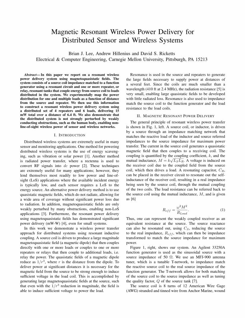
The general principle of resonant wireless power transferis shown in Fig. 1, left. A source coil, or inductor, is drivenby a source through an impedance matching network thatmatches the reactive load of the inductor and source referredimpedances to the source impedance for maximum powertransfer. The current in the source coil generates a quasistaticmagnetic field that then couples to a receiving coil. Thecoupling is quantified by the coupling coefficient, k, and themutual inductance, M = k
√LSLR. A voltage is induced on
the receiver coil due to the coupled field from the sourcecoil, which then drives a load. A resonating capacitor, CR,can be placed in the receiver circuit to resonate out the self-inductance of the receiver coil, resulting in a real impedancebeing seen by the source coil, through the mutual couplingof the two coils. The load resistance can be referred back tothe source coil using the mutual inductance, M , and is givenas [6]
Reff =ω2M2
RLoad. (1)
Thus, one can represent the weakly coupled receiver as anequivalent resistance at the source. The source reactancecan also be resonated out, using CS , reducing the sourceto the real impedance, Reff , which can then be impedancetransformed to match the source impedance for maximumpower.
Figure 1, right, shows our system. An Agilent 33250Afunction generator is used as the sinusoidal source with asource impedance of 50 Ω. We use an MFJ-900 antennatuner, which is a tunable T-network, to impedance matchthe reactive source coil to the real source impedance of thefunction generator. The T-network allows for both matchingof the source coil to the source impedance as well as tuningthe quality factor, Q of the source tank [7].
The source coil is 8 turns of 12 American Wire Gage(AWG) stranded and tinned wire from Anchor Marine, wound
Z
Match
Z
Match
CS
RLoad
Reff
VIN
50Ω
L1
RS1
10Ω
RL
RS4L4
L3
RS3C1
RS2
L2C2 VR
Func. Gen Z Match Source Coil
Load Network
RepeaterkS-R
k34
k12
k13k23
CR
+
_VS
+
_
LS LR
Fig. 1. Left: General analysis of resonant coupled coils. Right: Our experiential setup. We use one source coil and multiple load networksand repeaters, each of which identical to the circuit shown. The coupling lines ignore coupling between L4 and the source and repeater(s)to simplify the qualitative analysis of the system.
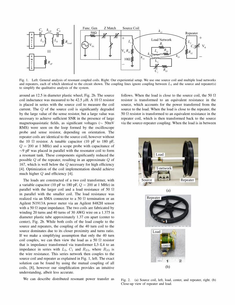
around an 12.5 in diameter plastic wheel, Fig. 2b. The sourcecoil inductance was measured to be 42.5 µH. A 10 Ω resistoris placed in series with the source coil to measure the coilcurrent. The Q of the source coil is significantly degradedby the large value of the sense resistor, but a large value wasnecessary to achieve sufficient SNR in the presence of largemagnetoquasistatic fields, as significant voltages (∼ 50mVRMS) were seen on the loop formed by the oscilloscopeprobe and sense resistor, depending on orientation. Therepeater coils are identical to the source coil, however withoutthe 10 Ω resistor. A tunable capacitor (10 pF to 180 pF,Q = 200 at 1 MHz) and a scope probe with capacitance of∼9 pF was placed in parallel with the resonator coil to forma resonant tank. These components significantly reduced thepossible Q of the repeater, resulting in an approximate Q of167, which is well below the Q necessary for high efficiency[4]. Optimization of the coil implementation should achievemuch higher Q and efficiency [4].
The loads are constructed of a two coil transformer, witha variable capacitor (10 pF to 180 pF, Q = 200 at 1 MHz) inparallel with the larger coil and a load resistance of 50 Ωin parallel with the smaller coil. The load resistance wasrealized via an SMA connector to a 50 Ω termination or anAgilent N1913A power meter via an Agilent 8482H sensorwith a 50 Ω input impedance. The two coils are fabricated bywinding 20 turns and 40 turns of 30 AWG wire on a 1.375 indiameter plastic tube approximately 1.37 cm apart (center tocenter), Fig. 2b. While both coils of the load couple to thesource and repeaters, the coupling of the 40 turn coil to thesource dominates due to its closer proximity and turns ratio.If we make a simplifying assumption that only the 40 turncoil couples, we can then view the load as a 50 Ω resistorthat is impedance transformed via transformer L3–L4 to animpedance in series with L3, C1 and RS3, where RS3 isthe wire resistance. This series network then couples to thesource coil and repeater as explained in Fig. 1, left. The exactsolution can be found by using the mutual coupling of allcoils, [8], however our simplification provides an intuitiveunderstanding, albeit less accurate.
We can describe distributed resonant power transfer as
follows. When the load is close to the source coil, the 50 Ωresistor is transformed to an equivalent resistance in thesource, which accounts for the power transferred from thesource to the load. When the load is close to the repeater, the50 Ω resistor is transformed to an equivalent resistance in therepeater coil, which is then transformed back to the sourcevia the source-repeater coupling. When the load is in between
(a)
(b)
RepeaterSource
Load
T-network
Repeater
Load
Fig. 2. (a) Source coil, left, load, center, and repeater, right. (b)Close-up view of repeater and load.

the source and repeater, it couples to the source directly andalso to the source via the repeater. The amount of powerdelivered can be determined simply from the transformedimpedances seen by the source coil. It is important to notethat the repeater also contains the series resistance of the coilitself. This resistance is also transformed to the source andrepresents a static power loss, along with the static power lossin the source coil itself, regardless of the number of loads.Finally, it should be noted that in our simplified picture weignore the de-tuning of the resonant circuits in the source,repeater and loads due to one another [8]. In our experimentwe determined that this is valid assumption when the sourceand repeater are separated by at least 35 cm. When they arecloser, a significant de-tuning of the coils is observed.
III. DESCRIPTION OF EXPERIMENT
To determine the ability to deliver distributed power overseveral meters, we conducted three experiments. In the first,we mount the source coil and one repeater coil on a tubularsupport such that the surface normal of both coils is in thesame direction, Fig. 2a. We then place a load between thesource and repeater coil and terminate the load with a powermeter. The repeater is placed 37 cm, 47 cm, 57 cm and 67cm from the source coil, measured center to center, and theload moved in 2.5 cm steps from the source to the repeater.To tune the system, we placed the repeater at the desiredposition and connected the input of the source T-network toan Agilent E8358A network analyzer and tune the T-networkto provide an S11 below -20 dB at 2.4 MHz with a narrowbandwidth, i.e. high Q. We then tuned the variable capacitorin the repeater so that its voltage was at a maximum. Thevariable capacitor in the load was then tuned for maximumpower at a distance of 2 cm from the source coil.
Figure 3 shows the power distribution as the load is moved.The power increases in the load as it approaches either thesource or the repeater. When the repeater is close to the
1.0
0.8
0.6
0.4
0.2
0
Nor
mal
ized
pow
er
Distance from source coil (cm)0 10 20 30 40 50 60
Load coil power vs. distance
67cm57cm47cm37cm
Fig. 3. Load power as a function of distance from source coilfor repeater-source distances of 37 cm, 47 cm, 57 cm and 67 cm.Distance from source was increased in 2.5 cm steps. Peak power foreach repeater-source distance is: 15 mW (37 cm separation), 19.1mW (47 cm separation), 19.6 mW (57 cm separation) and 18.3 mW(67 cm separation).
1086420Po
wer
del
iver
ed to
load
(mW
)
Distance from source coil (cm)0 10 20 305 15 35
Power distributed across single vs. multiple loads
25
Single load at each position Six loads simultaneously
1214
Fig. 4. Power transferred into 6 loads distributed evenly betweena source coil and repeater located 37 cm from source coil. Alsoshown is data from Fig. 3 for a single load that is moved in 2.5cm increments from source to repeater. The power delivered has thesame spatial trend for simultaneous loading and a single load.
source, it is able to deliver power to the load at a similarpower level as when the load is next to the source. As thedistance between source and repeater increase, the powerdelivered to the load near the repeater decreases owing tothe reduced coupling between the repeater and source.
In the second experiment, we choose a source-repeaterseparation of 37 cm and placed six evenly distributed loadsbetween the source and repeater in order to measure thepower delivered to multiple loads simultaneously. We mea-sured the power at each load with the power meter with allother loads terminated with 50 Ω terminations. Figure 4 plotsthe data of 6 loads as a function of distance from the source.Also plotted is the power delivered to single load at distancesfrom 4 to 32 cm from the source coil. The spatial powerdistribution trend is the same for both the simultaneous loadand single load case, with the simultaneous load case showinga lower power delivered to each load, as would be expected.The higher peak power in the simultaneous load case at 4cm is believed to be due to the high sensitivity to placementof the loads near the source and also the variance of powerreceived from load to load.
In our final experiment, we fabricated 4 repeaters and setupa distributed power system spanning 6.4 ft. The repeaterswere adjusted to deliver approximately 2.5 mW to the outermost loads. An additional 4 loads where then dispersed be-tween repeaters at locations that also produced approximately2.5 mW. Figure 5 shows the setup and the power deliveredto each load. Adjustment of loads throughout the systemproduced power profiles detailed in Table I.
In addition to the three quantitative experiments, we per-formed two qualitative experiments to test the robustness ofour approach. In order to test the system’s ability to operatein non-LoS environments, the authors moved about the testapparatus extensively to determine sensitivity to non-LoSconditions. When a human body was close to a repeater,a slight de-tuning would occur due to the presence of aweakly conducting obstruction (e.g. a human body). For a

Func. Gen.T-network
SourceLoad
-5”-16.4”-20”-36.5”-38.8” 0” 5” 15.5” 20.8” 36.5”38.3”
Repeater
Fig. 5. Distributed wireless power delivery. The center coil is the source coil and two repeaters are placed on either side of the sourcecoil. Locations were chosen to maximize power transferred to the outer most loads at 38 in. Four additional loads were placed between therepeaters as shown. Their locations were chosen to supply ∼ 2.5 mW each, or 15 mW total for 6 loads. Power transfer was not stronglyaffected by the presence of weakly conducting obstructions, e.g. the human body.
TABLE IPOWER DELIVERED TO DISTRIBUTED LOADS.
Component Distance (in) Power (mW)
Load 6 -38.8 2.32
Repeater 2 -36.5 n/a
Load 5 -20.0 2.51
Repeater 1 -16.4 n/a
Load 4 -5.0 2.74
Load 3 5.0 2.67
Repeater 3 15.5 n/a
Load 2 20.8 2.77
Repeater 1 36.6 n/a
Load 1 38.3 2.62
fixed obstruction the repeater could be re-tuned to give thesame power as when the obstruction was not present. Thisdemonstrated that the system is not strongly affected byweakly conducting obstructions and power reductions dueto obstructions can be mitigated by re-tuning the system.When the repeater coils were touched directly, a significantreduction in power was seen and the system could not be re-tuned. It is not known if this reduction in power was due toa significant de-tuning that could not be compensated withinour system parameters, or was the result of other phenomena.
To test the sensitivity of power transfer to the axial sym-metry of the system. Loads were moved, by hand, along thesurface of the repeater coils, from the center to outer radius.Power transfer was comparable for a given distance from therepeater along the entire radius, suggesting co-axial alignmentis not required. In addition, loads were rotated so that thesurface normal of the load coils were not parallel to thesource or repeaters. Power was still transferred but reduced asthe angle varied. While qualitative, these experiments showthat perfect co-axial symmetry is not necessary for powerdelivery. A quantitative analysis of possible orientations andpower delivery is beyond the scope of this brief paper.
IV. CONCLUSION
In this paper we presented magnetic resonant wirelesspower delivery for distributed sensor and wireless networks.We presented experimental measurements of resonant powerdelivery over varying distances for a single and multipleloads. We also demonstrated a distributed system that de-livered 15 mW to 6 loads (2.5 mW per load), over a distanceof 6.4 ft. We also showed that the system is not perturbed byweakly conducting bodies and is suitable for some non-LoSapplications.
V. ACKNOWLEDGEMENTS
This work was partially supported by QNRF under grantNPRP 09-667-1-100.
REFERENCES
[1] S. Roundy, P. K. Wright, and J. M. Rabaey, Energy Scavenging forWireless Sensor Networks with Special Focus on Vibrations, ser. ISBN:978-1-4020-7663-3. Springer, 2003.
[2] U. Olgun, C.-C. Chen, and J. Volakis, “Investigation of rectennaarray configurations for enhanced RF power harvesting,” Antennas andWireless Propagation Letters, IEEE, vol. 10, pp. 262 –265, 2011.
[3] D. Arumugam, J. Griffin, and D. Stancil, “Experimental Demonstrationof Complex Image Theory and Application to Position Measurement,”IEEE Antennas Wireless Propag. Lett., vol. 10, pp. 282 – 285, April2011.
[4] A. Kurs, A. Karalis, R. Moffatt, J. D. Joannopoulos, P. Fisher, andM. Soljacic, “Wireless power transfer via strongly coupled magneticresonances,” Science, vol. 317, no. 5834, pp. 83–86, 2007. [Online].Available: http://www.sciencemag.org/content/317/5834/83.abstract
[5] J. Jackson, “Classical Electrodynamics,” John Wiley and Sons Inc.,1999.
[6] C.-S. Wang, G. Covic, and O. Stielau, “Investigating an LCL loadresonant inverter for inductive power transfer applications,” PowerElectronics, IEEE Transactions on, vol. 19, no. 4, pp. 995 – 1002, july2004.
[7] T. H. Lee, The Design of CMOS Radio-Frequency Integrated Circuits.Cambridge University Press, 2004.
[8] B. Cannon, J. Hoburg, D. Stancil, and S. Goldstein, “Magnetic resonantcoupling as a potential means for wireless power transfer to multiplesmall receivers,” Power Electronics, IEEE Transactions on, vol. 24,no. 7, pp. 1819 –1825, july 2009.
Related Documents