1 VHDL Design with Algorithmic State Machine (ASM) Charts EL 310 Erkay Savaş Sabancı University

Welcome message from author
This document is posted to help you gain knowledge. Please leave a comment to let me know what you think about it! Share it to your friends and learn new things together.
Transcript
1
VHDLDesign with Algorithmic State
Machine (ASM) Charts
EL 310Erkay Savaş
Sabancı University
2
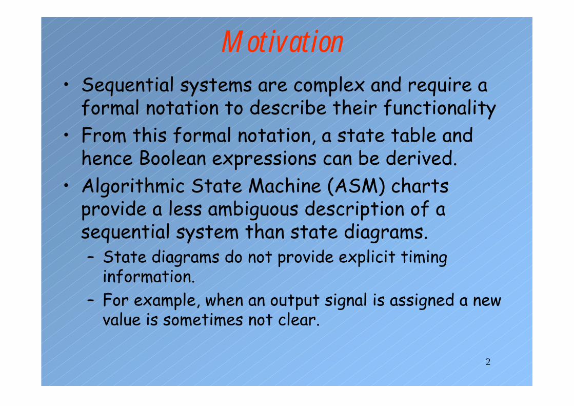
Motivation• Sequential systems are complex and require a
formal notation to describe their functionality• From this formal notation, a state table and
hence Boolean expressions can be derived.• Algorithmic State Machine (ASM) charts
provide a less ambiguous description of a sequential system than state diagrams.– State diagrams do not provide explicit timing
information.– For example, when an output signal is assigned a new
value is sometimes not clear.

3
State Diagram for a Traffic Signal Controller
Major road
Minor roadsensor
major=Gminor=R
car/start_timer
timed
timed’car’major=Rminor=G

4
ASM Chart for Traffic Controller• ASM charts resemble
flow charts, but contain implicit timing information
• ASM charts represent real hardware.
• Hardware cannot suddenly start or stop
• Therefore, all transitions within ASM charts must form closed paths (except a reset signal).
major=Greenminor=Red
G
major=Redminor=Green
R
car
start_timer
timed
0
0
1
1
5
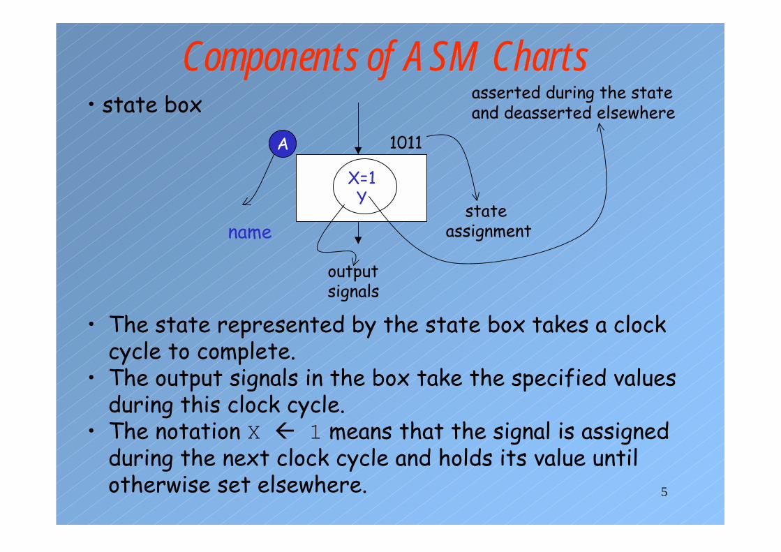
Components of ASM Charts
X=1Y
A
• state box
name
1011
state assignment
output signals
• The state represented by the state box takes a clock cycle to complete.
• The output signals in the box take the specified values during this clock cycle.
• The notation X � 1 means that the signal is assigned during the next clock cycle and holds its value until otherwise set elsewhere.
asserted during the state and deasserted elsewhere
6
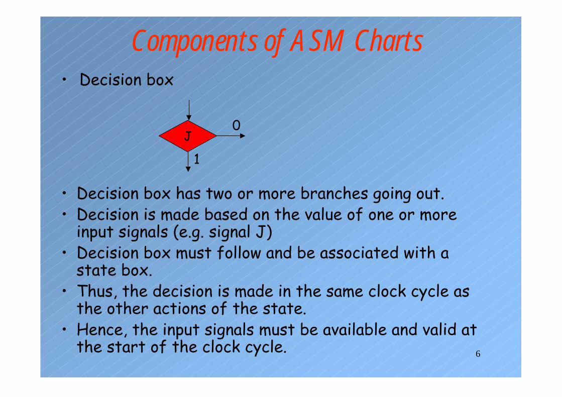
Components of ASM Charts• Decision box
J0
1
• Decision box has two or more branches going out.• Decision is made based on the value of one or more
input signals (e.g. signal J)• Decision box must follow and be associated with a
state box.• Thus, the decision is made in the same clock cycle as
the other actions of the state.• Hence, the input signals must be available and valid at
the start of the clock cycle.

7
Components of ASM Charts• Conditional output box
Z=1
• A conditional output box must follow a decision box.• A conditional output box is attached to a state box
through one or more decision boxes.• Therefore, the output signals in the conditional output
box are asserted in the same clock cycle as those inthe state box to which it is attached.
• The output signals can change during that state as aresult of changes on the inputs.
• The conditional output signals are sometimes referredas Mealy outputs since they depend on the input signalsas well.
8
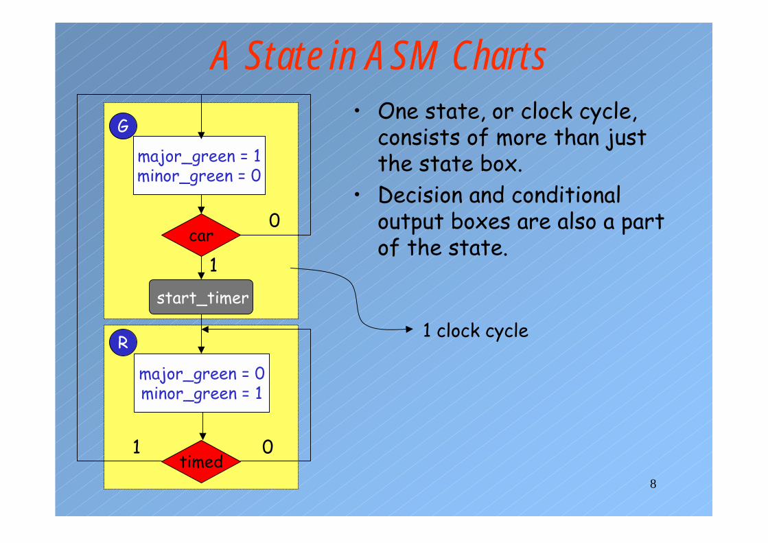
A State in ASM Charts• One state, or clock cycle,
consists of more than just the state box.
• Decision and conditional output boxes are also a part of the state.
major_green = 1minor_green = 0
G
major_green = 0minor_green = 1
R
car
start_timer
0
0
1
1timed
1 clock cycle
9
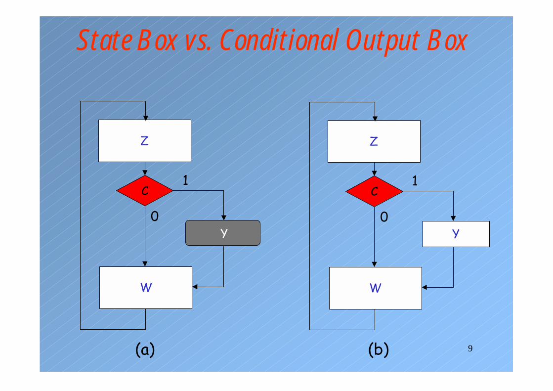
State Box vs. Conditional Output Box
Z
W
C
Y0
1
Z
W
C
0
1
Y
(a) (b)

10
State Box vs. Conditional Output Box
W
clock
Z
Y, C=1
Y, C=0
Z
Y, C=1
W, C=1
Y, C=0
W, C=0
(a)
(b)
C is tested here
11
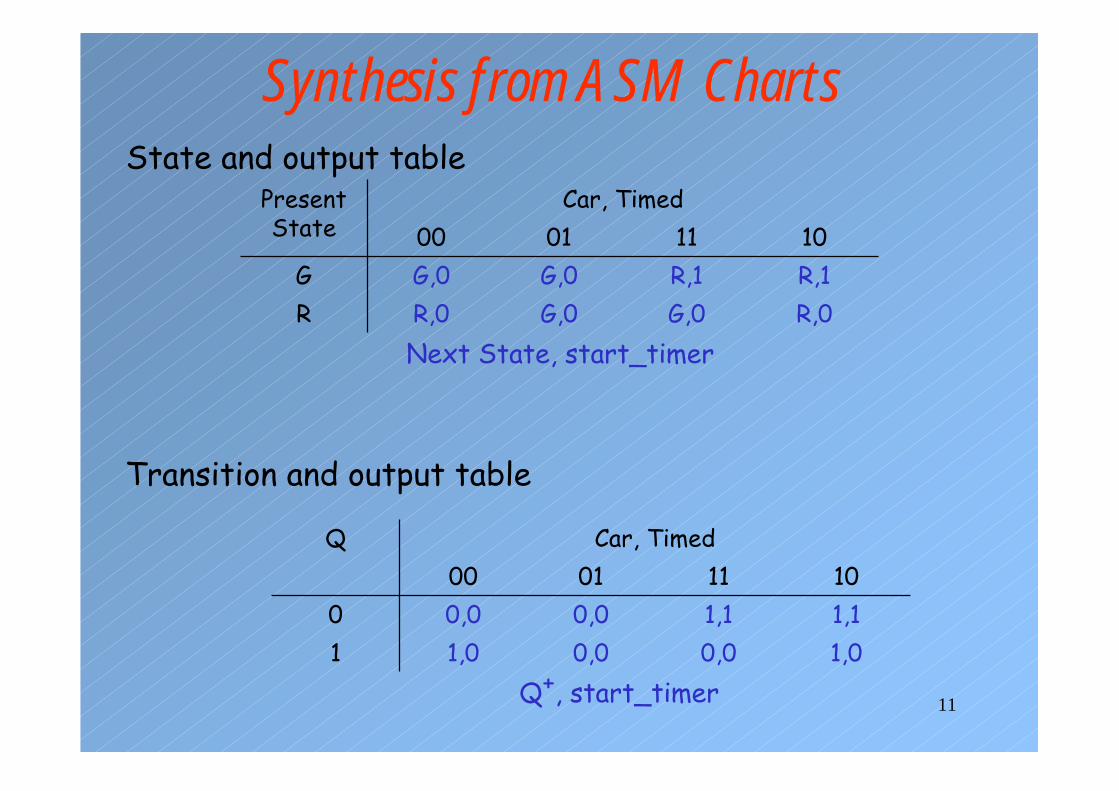
Synthesis from ASM Charts
Car, Timed
R,0G,0G,0R,0RR,1R,1G,0G,0G10110100
Present State
State and output table
Car, Timed
1,00,00,01,011,11,10,00,0010110100
Q
Transition and output table
Next State, start_timer
Q+, start_timer

12
K-Maps for Traffic Signal Controller
10011
11000101101
timed00
car,Q
Q+ = Q’ car + Q timed’
00001
11000101101
timed00
car,Q
start_timer = Q’ car
13
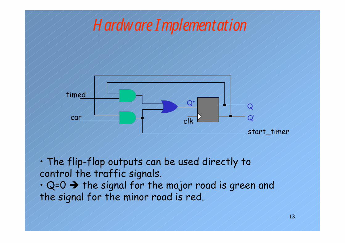
Hardware Implementation
timed
car
Q+Q
Q’
start_timerclk
• The flip-flop outputs can be used directly to control the traffic signals.• Q=0 � the signal for the major road is green and the signal for the minor road is red.
14
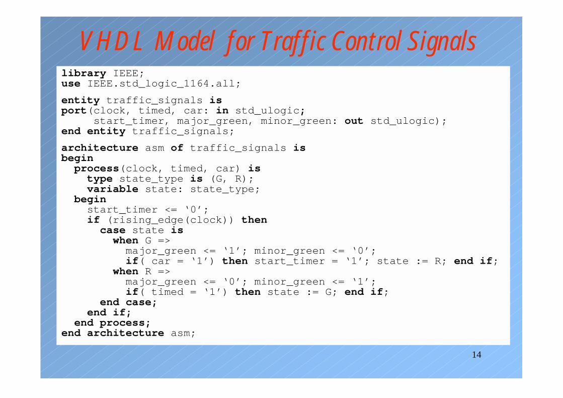
VHDL Model for Traffic Control Signalslibrary IEEE;use IEEE.std_logic_1164.all;
entity traffic_signals isport(clock, timed, car: in std_ulogic;
start_timer, major_green, minor_green: out std_ulogic);end entity traffic_signals;
architecture asm of traffic_signals isbegin
process(clock, timed, car) istype state_type is (G, R);variable state: state_type;
beginstart_timer <= ‘0’;if (rising_edge(clock)) then
case state iswhen G =>
major_green <= ‘1’; minor_green <= ‘0’;if( car = ‘1’) then start_timer = ‘1’; state := R; end if;
when R =>major_green <= ‘0’; minor_green <= ‘1’;if( timed = ‘1’) then state := G; end if;
end case;end if;
end process;end architecture asm;

15
Alternative VHDL Codearchitecture asm2 of traffic_signals is
type state_type is (G, R);variable state, next_state: state_type;
beginseq: process(clock) is -- for sequential partbegin
if (rising_edge(clock)) then state <= next_state; end if;end process seq;
com: process(timed, car, state) is -- for combinational partbegin
start_timer <= ‘0’;case state is
when G =>major_green <= ‘1’; minor_green <= ‘0’;if(car = ‘1’) then
start_timer = ‘1’; next_state <= R;else next_state <= G;end if;
when R =>major_green <= ‘0’; minor_green <= ‘1’;if( timed = ‘1’) then next_state <= G;else next_state <= R;end if;
end case;end process com;
end architecture asm2;
16
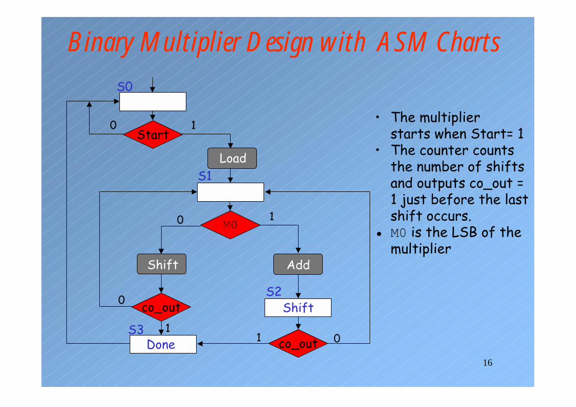
Binary Multiplier Design with ASM Charts
Start
Load
0 1M0
Shift Add
co_out Shift
S0
S1
S2
co_out 0S3
Done 11
0
10 • The multiplier starts when Start= 1
• The counter counts the number of shifts and outputs co_out = 1 just before the last shift occurs.
• M0 is the LSB of the multiplier
17
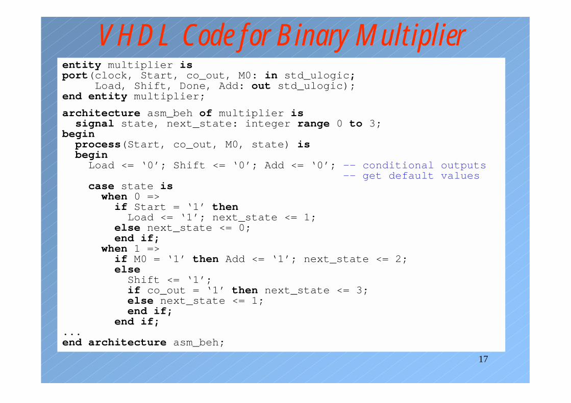
VHDL Code for Binary Multiplierentity multiplier isport(clock, Start, co_out, M0: in std_ulogic;
Load, Shift, Done, Add: out std_ulogic);end entity multiplier;
architecture asm_beh of multiplier issignal state, next_state: integer range 0 to 3;
beginprocess(Start, co_out, M0, state) isbegin
Load <= ‘0’; Shift <= ‘0’; Add <= ‘0’; -- conditional outputs-- get default values
case state iswhen 0 =>
if Start = ‘1’ thenLoad <= ‘1’; next_state <= 1;
else next_state <= 0;end if;
when 1 =>if M0 = ‘1’ then Add <= ‘1’; next_state <= 2;else
Shift <= ‘1’;if co_out = ‘1’ then next_state <= 3;else next_state <= 1;end if;
end if;...end architecture asm_beh;
18
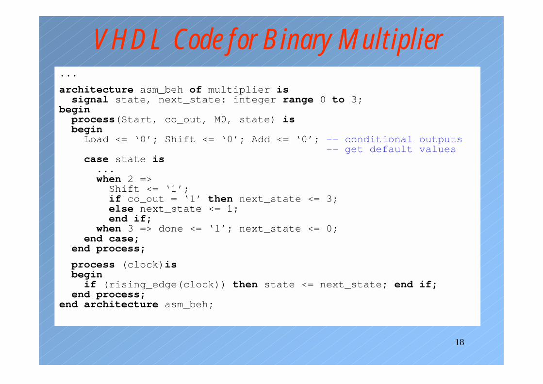
VHDL Code for Binary Multiplier...
architecture asm_beh of multiplier issignal state, next_state: integer range 0 to 3;
beginprocess(Start, co_out, M0, state) isbegin
Load <= ‘0’; Shift <= ‘0’; Add <= ‘0’; -- conditional outputs-- get default values
case state is...when 2 =>
Shift <= ‘1’;if co_out = ‘1’ then next_state <= 3;else next_state <= 1;end if;
when 3 => done <= ‘1’; next_state <= 0;end case;
end process;
process (clock)isbegin
if (rising_edge(clock)) then state <= next_state; end if;end process;
end architecture asm_beh;
19
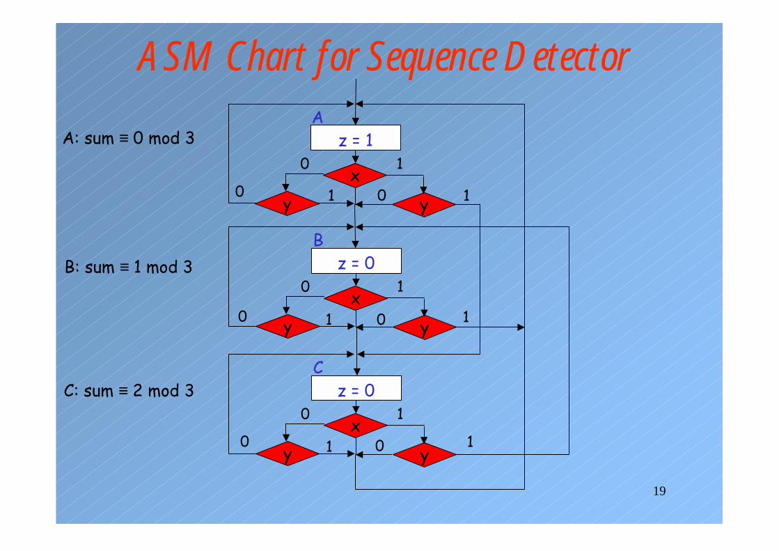
ASM Chart for Sequence DetectorA
z = 1
xy y
10
Bz = 0
xy y
10
Cz = 0
xy y
10
0 01
1
1
010
A: sum ≡ 0 mod 3
B: sum ≡ 1 mod 3
C: sum ≡ 2 mod 3
0 1 0 1
20
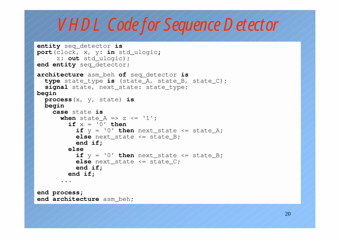
VHDL Code for Sequence Detectorentity seq_detector isport(clock, x, y: in std_ulogic;
z: out std_ulogic);end entity seq_detector;
architecture asm_beh of seq_detector istype state_type is (state_A, state_B, state_C);signal state, next_state: state_type;
beginprocess(x, y, state) isbegin
case state iswhen state_A => z <= ‘1’;
if x = ‘0’ thenif y = ‘0’ then next_state <= state_A;else next_state <= state_B;end if;
elseif y = ‘0’ then next_state <= state_B;else next_state <= state_C;end if;
end if;...
end process;end architecture asm_beh;
21
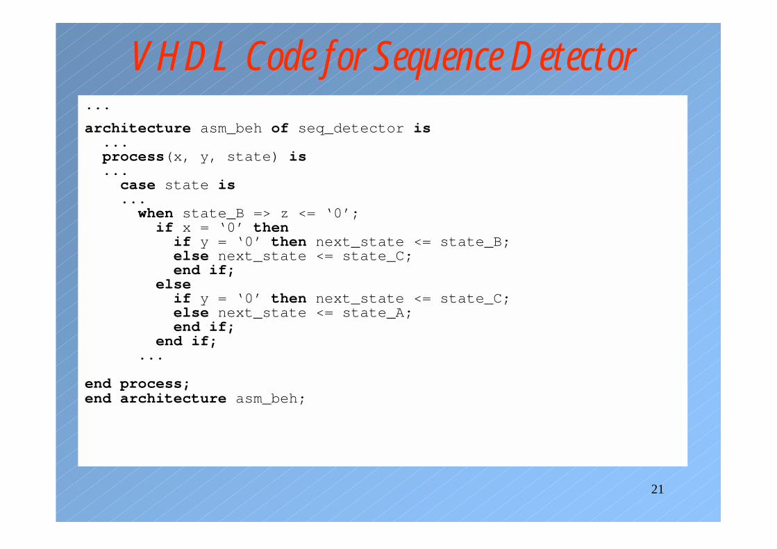
VHDL Code for Sequence Detector...
architecture asm_beh of seq_detector is...process(x, y, state) is...
case state is...
when state_B => z <= ‘0’;if x = ‘0’ then
if y = ‘0’ then next_state <= state_B;else next_state <= state_C;end if;
elseif y = ‘0’ then next_state <= state_C;else next_state <= state_A;end if;
end if;...
end process;end architecture asm_beh;
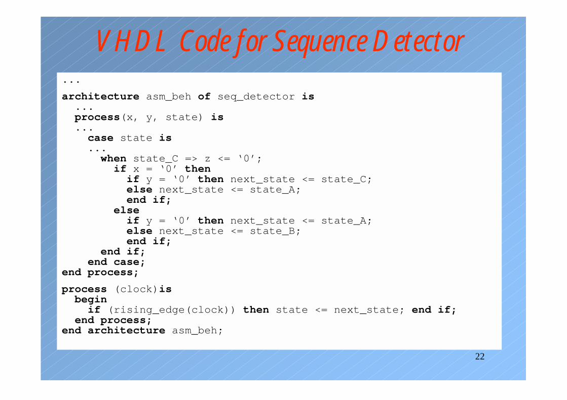
22
VHDL Code for Sequence Detector...
architecture asm_beh of seq_detector is...process(x, y, state) is...
case state is...
when state_C => z <= ‘0’;if x = ‘0’ then
if y = ‘0’ then next_state <= state_C;else next_state <= state_A;end if;
elseif y = ‘0’ then next_state <= state_A;else next_state <= state_B;end if;
end if;end case;
end process;
process (clock)isbegin
if (rising_edge(clock)) then state <= next_state; end if;end process;
end architecture asm_beh;
Related Documents