Journal of Engineering Science and Technology Review 6 (4) (2013) 74-80 Special Issue on Recent Advances in Nonlinear Circuits: Theory and Applications Research Article The Study of a Nonlinear Duffing – Type Oscillator Driven by Two Voltage Sources J. O. Maaita *, 1 , I. M. Kyprianidis 1 , Ch. K. Volos 2 , and E. Meletlidou 1 , 1 Dpt. Of Physics, Aristotle University of Thessaloniki, Thessaloniki, GR-54124, Greece 2 Faculty of Mathematics and Engineering Studies, Dpt. of Military Science, Hellenic Army Academy, Vari, GR-16673, Greece Received 2 September 2013; Revised 4 October 2013; Accepted 22 October 2013 ___________________________________________________________________________________________ Abstract In the present work, a detailed study of a nonlinear electrical oscillator with damping and external excitation is presented. The system under study consists of a Duffing-type circuit driven by two sinusoidal voltage sources having different frequencies. The dynamical behavior of the proposed system is investigated numerically, by solving the system of state equations and simulating its behavior as a circuit using MultiSim. The tools of the theoretical approach are the bifurcation diagrams, the Poincaré sections, the phase portraits, and the maximum Lyapunov exponent. The numerical investigation showed that the system has rich complex dynamics including phenomena such as quasiperiodicity, 3-tori, and chaos. Keywords: Nonlinear circuit, Duffing, chaos, quasiperiodicity, 3-tori, Poincaré section, maximum Lyapunov exponent. __________________________________________________________________________________________ 1. Introduction In the last decades, research activities in systems of nonlinear oscillators resulted in a lot of publications on phenomena that such systems exhibit [1, 2]. Also, the interesting dynamical behavior, which these systems have shown, has triggered an investigation in possible applications of such systems in various scientific fields, such as secure communications [3], cryptography [4], broadband communication systems [5] random number generators [6, 7], radars [8], robots [9] and in variety of complex physical, chemical and biological systems [10]. Especially, in the case of mechanical systems where the nonlinear attachments have small masses in comparison to the structures to which they are attached, and the systems are non conservative, various dynamical phenomena has been investigated [11-13]. A special property of these configurations is that the nonlinear substructures can act as nonlinear energy sinks (NESs) and absorb, through irreversible transient transfer, energy from the linear parts [14-16]. Such systems can be easily implemented by nonlinear electrical circuits [17, 18]. The first who did this was Professor Leon Chua in 1983. At that time, there was a deep desire to implement nonlinear circuits that allow the experimental demonstration of various phenomena, especially chaos, in order to refuse the claim that these phenomena were only a mathematical invention. This led Chua to investigate the possibility of designing an autonomous circuit behaving in a chaotic way [19]. So, this approach helps us to make experiments testing the dynamical behavior of nonlinear oscillators. In this work we have used an electronic circuit to implement a nonlinear and non-autonomous oscillator with damping. Such systems have been studied in previous works [20, 21] and have rich dynamics depending on the different parameters and especially on the damping parameter λ. In more details, the proposed system is a Duffing-type nonlinear oscillator, which is driven by two sinusoidal voltage sources with different frequencies. We have made the simulations of the electrical circuit with the use of the MultiSim platform and we have also solved numerically the nonlinear system of differential equations using programming languages, such as Mathematica and TrueBasic. Furthermore, the estimation of maximum Lyapunov exponent and the Poincaré sections help us to identify the dynamical behavior of the above system. Finally, various types of oscillation such as periodic, quasiperiodic, and chaotic have been shown. In the case of periodic response, the maximum Lyapunov exponent is negative, in the case of quasiperiodic response, the maximum Lyapunov exponent equals to zero, while in the case of chaotic response, the maximum Lyapunov exponent is positive. This manuscript is organized as follows. In Section 2, the proposed nonlinear system and the electronic circuit, which realizes the system, are presented. The dynamical behavior of the proposed system and the simulation results are presented in Section 3. Finally, the conclusion remarks are presented in Section 4. 2. The Nonlinear System and the Proposed Electric Circuit Jestr JOURNAL OF Engineering Science and Technology Review www.jestr.org ______________ * E-mail address: [email protected] ISSN: 1791-2377 © 2013 Kavala Institute of Technology. All rights reserved.

Welcome message from author
This document is posted to help you gain knowledge. Please leave a comment to let me know what you think about it! Share it to your friends and learn new things together.
Transcript
Journal of Engineering Science and Technology Review 6 (4) (2013) 74-80
Special Issue on Recent Advances in Nonlinear Circuits: Theory and Applications
Research Article
The Study of a Nonlinear Duffing – Type Oscillator Driven by Two Voltage Sources
J. O. Maaita*, 1, I. M. Kyprianidis1, Ch. K. Volos2, and E. Meletlidou1,
1Dpt. Of Physics, Aristotle University of Thessaloniki, Thessaloniki, GR-54124, Greece 2Faculty of Mathematics and Engineering Studies, Dpt. of Military Science, Hellenic Army Academy, Vari, GR-16673, Greece
Received 2 September 2013; Revised 4 October 2013; Accepted 22 October 2013
___________________________________________________________________________________________ Abstract In the present work, a detailed study of a nonlinear electrical oscillator with damping and external excitation is presented. The system under study consists of a Duffing-type circuit driven by two sinusoidal voltage sources having different frequencies. The dynamical behavior of the proposed system is investigated numerically, by solving the system of state equations and simulating its behavior as a circuit using MultiSim. The tools of the theoretical approach are the bifurcation diagrams, the Poincaré sections, the phase portraits, and the maximum Lyapunov exponent. The numerical investigation showed that the system has rich complex dynamics including phenomena such as quasiperiodicity, 3-tori, and chaos.
Keywords: Nonlinear circuit, Duffing, chaos, quasiperiodicity, 3-tori, Poincaré section, maximum Lyapunov exponent. __________________________________________________________________________________________ 1. Introduction In the last decades, research activities in systems of nonlinear oscillators resulted in a lot of publications on phenomena that such systems exhibit [1, 2]. Also, the interesting dynamical behavior, which these systems have shown, has triggered an investigation in possible applications of such systems in various scientific fields, such as secure communications [3], cryptography [4], broadband communication systems [5] random number generators [6, 7], radars [8], robots [9] and in variety of complex physical, chemical and biological systems [10].
Especially, in the case of mechanical systems where the nonlinear attachments have small masses in comparison to the structures to which they are attached, and the systems are non conservative, various dynamical phenomena has been investigated [11-13]. A special property of these configurations is that the nonlinear substructures can act as nonlinear energy sinks (NESs) and absorb, through irreversible transient transfer, energy from the linear parts [14-16].
Such systems can be easily implemented by nonlinear electrical circuits [17, 18]. The first who did this was Professor Leon Chua in 1983. At that time, there was a deep desire to implement nonlinear circuits that allow the experimental demonstration of various phenomena, especially chaos, in order to refuse the claim that these phenomena were only a mathematical invention. This led Chua to investigate the possibility of designing an autonomous circuit behaving in a chaotic way [19]. So, this
approach helps us to make experiments testing the dynamical behavior of nonlinear oscillators.
In this work we have used an electronic circuit to implement a nonlinear and non-autonomous oscillator with damping. Such systems have been studied in previous works [20, 21] and have rich dynamics depending on the different parameters and especially on the damping parameter λ. In more details, the proposed system is a Duffing-type nonlinear oscillator, which is driven by two sinusoidal voltage sources with different frequencies. We have made the simulations of the electrical circuit with the use of the MultiSim platform and we have also solved numerically the nonlinear system of differential equations using programming languages, such as Mathematica and TrueBasic. Furthermore, the estimation of maximum Lyapunov exponent and the Poincaré sections help us to identify the dynamical behavior of the above system. Finally, various types of oscillation such as periodic, quasiperiodic, and chaotic have been shown.
In the case of periodic response, the maximum Lyapunov exponent is negative, in the case of quasiperiodic response, the maximum Lyapunov exponent equals to zero, while in the case of chaotic response, the maximum Lyapunov exponent is positive.
This manuscript is organized as follows. In Section 2, the proposed nonlinear system and the electronic circuit, which realizes the system, are presented. The dynamical behavior of the proposed system and the simulation results are presented in Section 3. Finally, the conclusion remarks are presented in Section 4. 2. The Nonlinear System and the Proposed Electric Circuit
Jestr JOURNAL OF Engineering Science and Technology Review
www.jestr.org
______________ * E-mail address: [email protected]
ISSN: 1791-2377 © 2013 Kavala Institute of Technology. All rights reserved.
J. O. Maaita, I. M. Kyprianidis, Ch. K. Volos, and E. Meletlidou/ Journal of Engineering Science and Technology Review 6 (4) (2013) 74-80
75
The nonlinear and non-autonomous system with damping, [20, 21], is described by the following set of differential equations:
311 22
dx yd
dy y cx Asin(2 f ) Bsin(2 f )d
⎧ =⎪ τ⎪⎨⎪ = −λ − + π τ + π τ⎪ τ⎩
(1)
where λ is the damping parameter, c is the coefficient of the nonlinear term, A, B are the amplitudes of the external sinusoidal excitations and f11, f22 their frequencies. We must notice here, that although there are no limits in the values of the frequencies, interesting dynamical phenomena occur, when the ratio of the frequencies
11f and 22f is irrational.
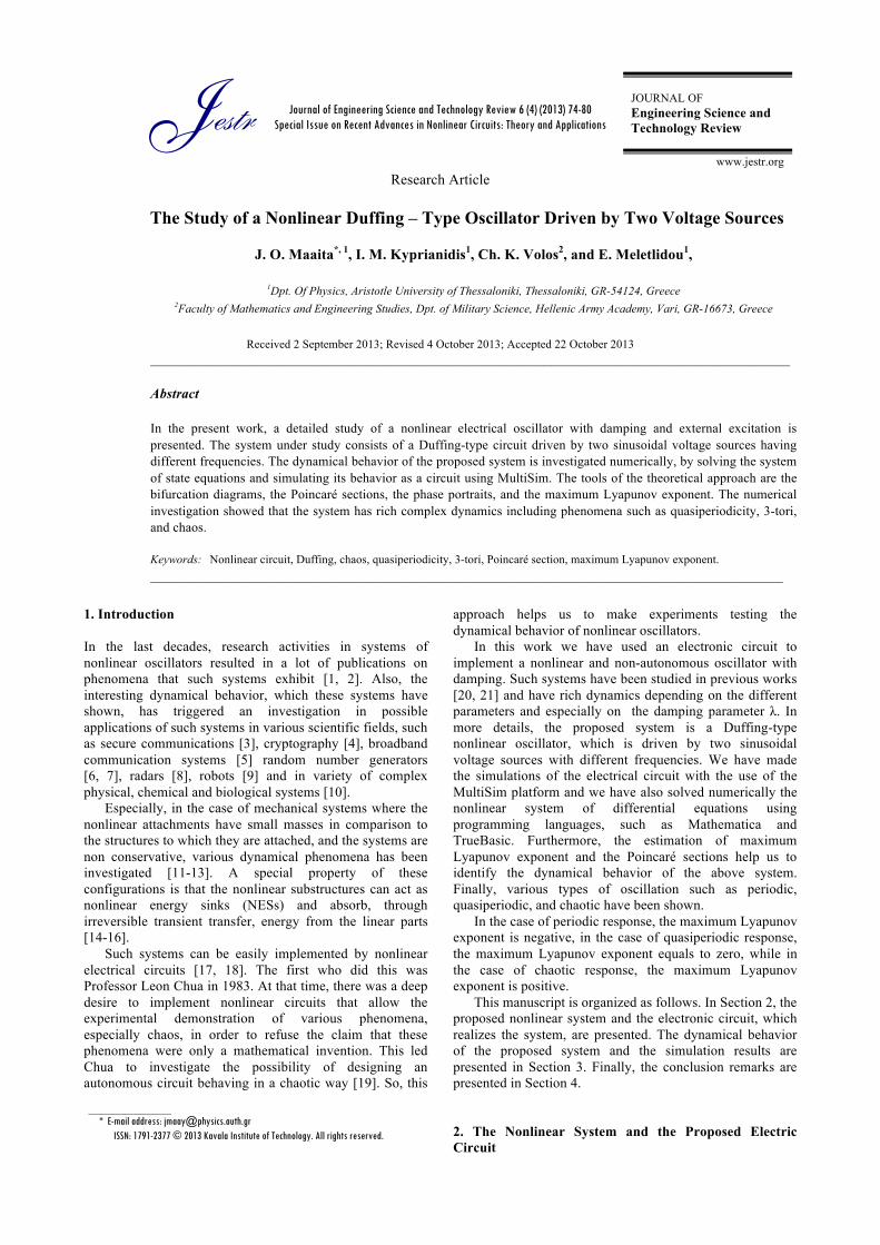
The circuit topology that was adopted in the MultiSim platform in order to realize the system’s equations (1), is presented in Fig.1.
Fig. 1. The proposed circuit emulating the nonlinear system.
The proposed circuit consists of two identical operational amplifiers U1, U2 (LF411), and two multipliers U3, U4 (AD734AN). Also, it should be mentioned that the signals x and y represent the voltages at the outputs of the operational amplifiers U1 and U2, while U3 and U4 realize the cubic term cx3. Finally, the DC voltages used for all the ICs were V± = ± 15 V.
In the system’s equations (1), parameters λ, c, A, B, f11 and f22 are defined as follows:
1
5
R2R
λ = , 1
2
Rc200R
= , 101
3
RA V2R
= , 102
4
RB V2R
= ,
111 1
R Cf f2
= , 122 2
R Cf f2
= (2)
Also, the normalized time (τ) is 1 tτ =α
, where 1R C2
α =
is the time constant of the circuit. The circuit’s elements values are: R1 = 10 kΩ and C = 10 nF, while the rest of the components (R2, R3, R4, R5, V1, V2, f11 and f22) can be varied, in order to have a complete view of the dependence of the circuit on the values of the system’s parameters. 3. Simulation Results We have studied the above circuit of Fig.1 using the Multisim platform and programming languages such as Mathematica and TrueBasic. The parameter c was fixed to be c = 0.2, while the amplitudes A, B and the frequencies f11, f12 of the voltage sources respectively, can be varied. For the damping coefficient λ, we have used λ > 0.05, in order to focus to more complex dynamics.
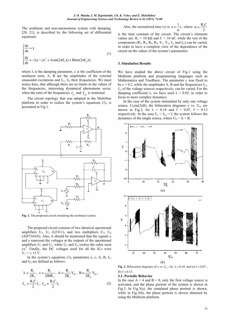
In the case of the system stimulated by only one voltage source, U0sin(2πft), the bifurcation diagrams x vs. U0, are shown in Fig.2, for λ = 0.10 and f = 0.07, f = 0.13 respectively. In the case f11 = f22 = f, the system follows the dynamics of the single source, where U0 = A + B.
(a)
(b)
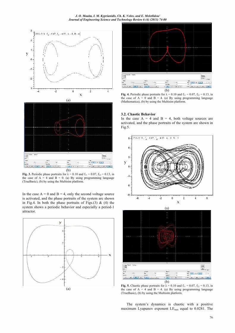
Fig. 2. Bifurcation diagrams of x vs. 0U , for λ 0.10= and (a) f 0.07= , (b) f 0.13= . 3.1. Periodic Behavior In the case A = 4 and B = 0, only the first voltage source is activated, and the phase portrait of the system is shown in Fig.3. In Fig.3(a), the simulated phase portrait is shown, while in Fig.3(b), the phase portrait is shown obtained by using the Multisim platform.
J. O. Maaita, I. M. Kyprianidis, Ch. K. Volos, and E. Meletlidou/ Journal of Engineering Science and Technology Review 6 (4) (2013) 74-80
76
(a)
(b)
Fig. 3. Periodic phase portraits for λ = 0.10 and f11 = 0.07, f22 = 0.13, in the case of A = 4 and B = 0. (a) By using programming language (TrueBasic), (b) by using the Multisim platform. In the case A = 0 and B = 4, only the second voltage source is activated, and the phase portraits of the system are shown in Fig.4. In both the phase portraits of Figs.(3) & (4) the system shows a periodic behavior and especially a period-1 attractor.
(a)
(b)
Fig. 4. Periodic phase portraits for λ = 0.10 and f11 = 0.07, f22 = 0.13, in the case of A = 0 and B = 4. (a) By using programming language (Mathematica), (b) by using the Multisim platform. 3.2. Chaotic Behavior In the case A = 4 and B = 4, both voltage sources are activated, and the phase portraits of the system are shown in Fig.5.
(a)
(b)
Fig. 5. Chaotic phase portraits for λ = 0.10 and f11 = 0.07, f22 = 0.13, in the case of A = 4 and B = 4. (a) By using programming language (TrueBasic), (b) by using the Multisim platform.
The system’s dynamics is chaotic with a positive maximum Lyapunov exponent LEmax equal to 0.0281. The
J. O. Maaita, I. M. Kyprianidis, Ch. K. Volos, and E. Meletlidou/ Journal of Engineering Science and Technology Review 6 (4) (2013) 74-80
77
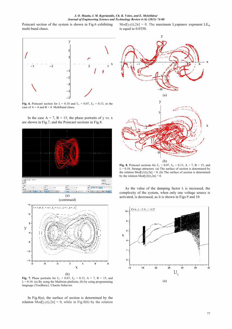
Poincaré section of the system is shown in Fig.6 exhibiting multi-band chaos.
Fig. 6. Poincaré section for λ = 0.10 and f11 = 0.07, f22 = 0.13, in the case of A = 4 and B = 4. Multiband chaos.
In the case A = 7, B = 15, the phase portraits of y vs. x are shown in Fig.7, and the Poincaré sections in Fig.8.
(a)
(continued)
(b)
Fig. 7. Phase portraits for f11 = 0.07, f22 = 0.13, A = 7, B = 15, and λ = 0.10: (a) By using the Multisim platform, (b) by using programming language (TrueBasic). Chaotic behavior.
In Fig.8(a), the surface of section is determined by the relation Mod[γ1(t),2π] = 0, while in Fig.8(b) by the relation
Mod[γ2(t),2π] = 0. The maximum Lyapunov exponent LEm is equal to 0.0350.
(a)
(b)
Fig. 8. Poincaré sections for f11 = 0.07, f22 = 0.13, A = 7, B = 15, and λ = 0.10. Strange attractors. (a) The surface of section is determined by the relation Mod[γ1(t),2π] = 0, (b) The surface of section is determined by the relation Mod[γ2(t),2π] = 0.
As the value of the damping factor λ is increased, the complexity of the system, when only one voltage source is activated, is decreased, as it is shown in Figs.9 and 10.
(a)
J. O. Maaita, I. M. Kyprianidis, Ch. K. Volos, and E. Meletlidou/ Journal of Engineering Science and Technology Review 6 (4) (2013) 74-80
78
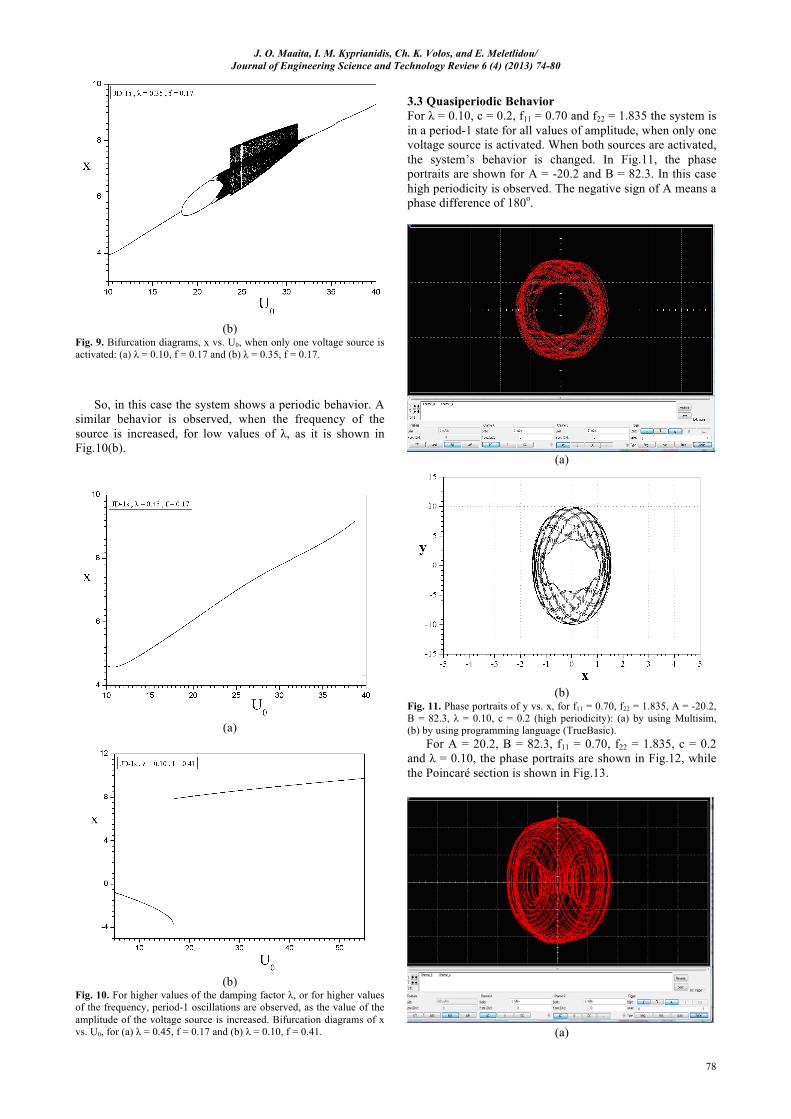
(b)
Fig. 9. Bifurcation diagrams, x vs. U0, when only one voltage source is activated: (a) λ = 0.10, f = 0.17 and (b) λ = 0.35, f = 0.17.
So, in this case the system shows a periodic behavior. A similar behavior is observed, when the frequency of the source is increased, for low values of λ, as it is shown in Fig.10(b).
(a)
(b)
Fig. 10. For higher values of the damping factor λ, or for higher values of the frequency, period-1 oscillations are observed, as the value of the amplitude of the voltage source is increased. Bifurcation diagrams of x vs. U0, for (a) λ = 0.45, f = 0.17 and (b) λ = 0.10, f = 0.41.
3.3 Quasiperiodic Behavior For λ = 0.10, c = 0.2, f11 = 0.70 and f22 = 1.835 the system is in a period-1 state for all values of amplitude, when only one voltage source is activated. When both sources are activated, the system’s behavior is changed. In Fig.11, the phase portraits are shown for A = -20.2 and B = 82.3. In this case high periodicity is observed. The negative sign of A means a phase difference of 180o.
(a)
(b)
Fig. 11. Phase portraits of y vs. x, for f11 = 0.70, f22 = 1.835, A = -20.2, B = 82.3, λ = 0.10, c = 0.2 (high periodicity): (a) by using Multisim, (b) by using programming language (TrueBasic).
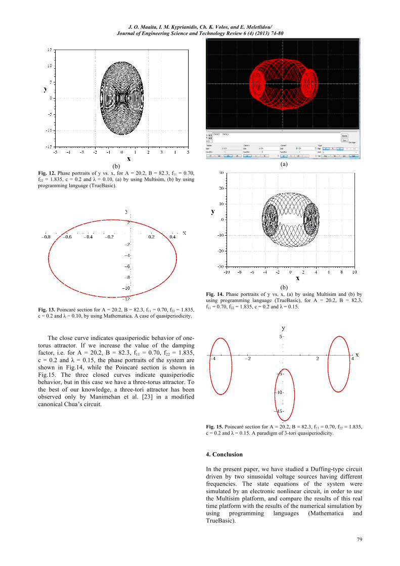
For A = 20.2, B = 82.3, f11 = 0.70, f22 = 1.835, c = 0.2 and λ = 0.10, the phase portraits are shown in Fig.12, while the Poincaré section is shown in Fig.13.
(a)
J. O. Maaita, I. M. Kyprianidis, Ch. K. Volos, and E. Meletlidou/ Journal of Engineering Science and Technology Review 6 (4) (2013) 74-80
79
(b)
Fig. 12. Phase portraits of y vs. x, for A = 20.2, B = 82.3, f11 = 0.70, f22 = 1.835, c = 0.2 and λ = 0.10, (a) by using Multisim, (b) by using programming language (TrueBasic).
Fig. 13. Poincaré section for A = 20.2, B = 82.3, f11 = 0.70, f22 = 1.835, c = 0.2 and λ = 0.10, by using Mathematica. A case of quasiperiodicity.
The close curve indicates quasiperiodic behavior of one-torus attractor. If we increase the value of the damping factor, i.e. for A = 20.2, B = 82.3, f11 = 0.70, f22 = 1.835, c = 0.2 and λ = 0.15, the phase portraits of the system are shown in Fig.14, while the Poincaré section is shown in Fig.15. The three closed curves indicate quasiperiodic behavior, but in this case we have a three-torus attractor. To the best of our knowledge, a three-tori attractor has been observed only by Manimehan et al. [23] in a modified canonical Chua’s circuit.
(a)
(b)
Fig. 14. Phase portraits of y vs. x, (a) by using Multisim and (b) by using programming language (TrueBasic), for A = 20.2, B = 82.3, f11 = 0.70, f22 = 1.835, c = 0.2 and λ = 0.15.
Fig. 15. Poincaré section for A = 20.2, B = 82.3, f11 = 0.70, f22 = 1.835, c = 0.2 and λ = 0.15. A paradigm of 3-tori quasiperiodicity. 4. Conclusion
In the present paper, we have studied a Duffing-type circuit driven by two sinusoidal voltage sources having different frequencies. The state equations of the system were simulated by an electronic nonlinear circuit, in order to use the Multisim platform, and compare the results of this real time platform with the results of the numerical simulation by using programming languages (Mathematica and TrueBasic).
J. O. Maaita, I. M. Kyprianidis, Ch. K. Volos, and E. Meletlidou/ Journal of Engineering Science and Technology Review 6 (4) (2013) 74-80
80
The simulations confirmed the rich dynamics of the above nonlinear system. Depending on the system parameters, periodic, quasiperiodic and chaotic oscillations were observed. Important role in the dynamics of the system plays the damping parameter λ, and the frequencies f11 and f22 of the external sinusoidal voltage sources. The simultaneous excitation of the circuit by two different input
signals gives rise to unpredictable dynamics and the response of the system, i.e. the output signal, can be used as a random generator.
The quasiperiodic behavior and the observation of a 3-tori attractor is quite a new dynamics for a Duffing-type system.
______________________________ References
1. G. Chen and X. Dong, From Chaos to Order: Methodologies,
Perspective and. Applications, World Scientific, Singapore (1998).
2. G. Chen and X. Yu, Berlin, Chaos control: theory and applications, Springer-Verlag, Heidelberg (2003).
3. C.K. Tse and F. Lau, Chaos-based Digital Connunication Systems: Operating Principles, Analysis Methods, and Performance Evaluation, Springer Verlag, New York (2003).
4. Ch.K. Volos, I.M. Kyprianidis, and I.N. Stouboulos, WSEAS Trans. Circuits Syst. 5, 1654 (2006).
5. A.S. Dimitriev, A.V. Kletsovi, A.M. Laktushkin, A.I. Panas, and S.O. Starkov, J. Communications Technology Electronics 51, 1126 (2006).
6. Ch.K. Volos, I.M. Kyprianidis, and I.N. Stouboulos, Signal Processing 93, 1328 (2013).
7. Ch.K. Volos, I.M. Kyprianidis, and I.N. Stouboulos, Int. J. Multimedia Intelligence and Security, 1, 320 (2010).
8. T. Jiang, S. Qiao, Z. Shi, L. Peng, and J. Huangfu, Progress In Electromagnetics Research 90, 15 (2009).
9. Ch.K. Volos, I.M. Kyprianidis, and I.N. Stouboulos, Journal of Engineering Science and Technology Review 5, 6 (2012).
10. S.H. Strogatz, Nonlinear Dynamics and Chaos, Westview Press, Cambridge (1994).
11. O.V. Gendelman, A.F. Vakakis, L.A. Bergman, and D.M. McFarland, SIAM Journal on Applied Mathematics 70, 1655
(2010). 12. O.V. Gendelman, L.I. Manevitch, A.F. Vakakis, R. M’Closkey,
Transaction of the ASME 68, 34 (2001). 13. A.F. Vakakis, Nonlinear Dynamics 61, 443 (2010). 14. O.V. Gendelman, Y. Starosvetsky, and M. Feldman, Nonlinear
Dynamics 51, 31 (2008). 15. T. Sapsis, A.F. Vakakis, O.V. Gendelman, L.A. Bergman, G.
Kerschen, and D.D.Quinn,. J. Sound Vib. 325, 297 (2009). 16. A.F. Vakakis, O.V. Gendelman, L.A. Bergman, D.M. McFarland,
G. Kerschen, and Y.S. Lee, Springer, (2008). 17. I.M. Kyprianidis, Ch.K. Volos, I.N. Stouboulos, and J.
Hadjidemetriou, Int. J. Bifurc. Chaos 16, 1765 (2006). 18. Ch.K. Volos, I.M. Kyprianidis, I.N. Stouboulos, and A.N.
Anagnostopoulos, J. Applied Functional Analysis 4, 703 (2009). 19. L.O. Chua, Archiv fur Elektronik und Ubertragungstechnik 46,
250 (1992). 20. J.O. Maaita, E. Meletlidou, A.F. Vakakis, and V. Rothos, Journal
of Applied Nonlinear Dynamics, 4, 315 (2013). 21. J.O. Maaita, E. Meletlidou, A.F. Vakakis, and V. Rothos, Journal
of Applied Nonlinear Dynamics, In Press. 22. A. Wolf., J. B. Swift, H. L. Swinney, and J. A. Vastano, Physica
D16, 285 (1985). 23. I. Manimehan, K. Thamilmaran, and P. Philominathan, Int. J.
Bifurc. Chaos 21, 1987 (2011).
Related Documents


