GE Fanuc Au Programmable Control Products Logicmaster m I Family Programming and Documentation Software User’s Manual GFK4075A October 7989

Welcome message from author
This document is posted to help you gain knowledge. Please leave a comment to let me know what you think about it! Share it to your friends and learn new things together.
Transcript
GE Fanuc Au
Programmable Control Products
Logicmaster m I FamilyProgramming andDocumentation Software
User’s Manual
GFK4075A October 7989
GFL-002
Warnings, Cautions, and Notesas Used in this Publication
Warning notices are used in this publication to emphasize that hazardous voltages, cur-rents, temperatures, or other conditions that could cause personal injury exist in thisequipment or may be associated with its use.
In situations where inattention could cause either personal injury or damage to equip-ment, a Warning notice is used.
1 Caution 1Caution notices are used where equipment might be damaged if care is not taken.
Note
Notes merely call attention to information that is especially significant to understandingand operating the equipment.
This document is based on information available at the time of its publication. While ef-forts have been made to be accurate, the information contained herein does not purportto cover all details or variations in hardware or software, nor to provide for every pos-sible contingency in connection with installation, operation, or maintenance. Featuresmay be described herein which are not present in all hardware and s&ware systems.GE Fanuc Automation assumes no obligation of notice to holders of this document withrespect to changes subsequently made.
GE Fanuc Automation makes no representation or warranty, expressed, implied, or stat-utory with respect to, and assumes no responsibility for the accuracy, completeness, suf-ficiency, or usefulness of the information contained herein. No warranties of merchant-ability or fitness for purpose shall apply.
The following are trademarks of GE Fanuc Automation North America, Inc.
Alarm Master CIMSTm Helpmate PROMACRO Series SixCIMPIKITY GEnet Logicmaster Series One Series 90CIMPLKITY 900ADS Genius Modelmaster Series Three VLlMaskrCIh4PLIClTY PowerTRAC Genius PowerTRAC ProLoop Series Five Workmaster
@Copfight 1992 GE Fanuc Automation North limerica, Inc.All-Rights Reserved
Preface . . .ill
GFK-0075
PREFACE
The Logicmaster’” 1F Programming and Documentation Software packages from GEFanuc Automation North America, Inc. are used to create ladder logic programs for theSeries Or@” family of programmable logic controllers (PLCs). This manual describes theLogicmaster 1 Family software package to be used with either the Series One (Model E)of Series One Plus PLC.
Programming and documentation software is also available for the Series One and SeriesOne Junior PLCs. For the most part, this manual applies to those software packages aswell. Where differences do exist, they have been described in Appendix E for theLogicmaster 1 software package and Appendix F for the Logicmaster 1 Junior softwarepackage.
USING THIS MANUAL .
Chapters 1 through 11 describe the features of the Logicmaster 1 F software package. Ifyou are starting up the system for the first time, or getting ready to do a print-out, ordisplaying tables of data from the Series One PLC, for example, you will refer to thechapter describing the function you want to use.
Chapters 12 and 13 are for the programmer. Use them as a reference to the basicprogramming instruct ions and data operation instructions.
Appendices E and F describe the Logicmaster 1 and Logicmaster 1 Junior softwarepackages.
The manual is organized as follows:
Chapter I. Introduction: provides an overview of the software package, the hardwarerequirements, and options for running Logicmaster 1F software. Chapter 1 describes thehardware requirements for using -the software, plus the system’s different modes ofoperation. A brief description of the principal features of the product is also provided.
Chapter 2. Operation: covers the start-up procedures for floppy diskette and hard diskusers. Also, the basics of operation of the Workmaster@ computer, Workmaster@ IIcomputer, Cimstaffn I computer, and IEHvI personal computers when using Logicmaster 1Fsoftware are included.
Chapter 3. Scratch Pad: defines the entries on the Scratch Pad display, and explains howto change these entries.
Chapter 4. Display Program: explains how to use the features of Display Program:displaying a program, searching for a program element, and making on-line changes.
Chapter 5. Edit Proaram: exDiains how to use Loclicmaster IF software to enter andmodify a ladder logic program: entering the Edit ?Togtam mode, editing the program,editing a rung, searching for a program element, and ladder diagram file editing.
Chapter 6. Annotation: explains how to create, display, and print annotation.
Chapter 7. Display Reference Tables: explains how to enter, use, and exit the DisplayReference Tables function.
iv Preface
GFK-0075
Chapter 8. Print: explains how to use the Print functions: setting up the printer,defining print-out content, printing in Foreground mode, and printing a file in Backgroundmode. A description of the Print menu includes a summary of the Print function keys.
Chapter9 . Load/Store/Verify: explains the Load/Store/Verify functions: loading aprogram into programmer memory, storing data from programmer memory, verifying thecontent of a program, and clearing memory. A summary of the Load/Store/Verify menufunction keys is also provided.
Chapter 10. Configuration Setup: explains the Communications Setup and Machine Setupfunctions. Refer to chapter 10 for information on CPU password protection, andlocking/unlocking the CPU. A summary of the function keys is also provided.
Chapter 11 l Utilities: explains how to use the Utilities functions for disk and filemanagement, for configuring the serial port(s), and for clearing parity errors in the CPU.A description of the Utilities menu includes a summary of the function keys.
Chapter 12. Programming: explains general programming concepts and describes basicprogramming instructions for the Series One (Model E) and Series One Plus PLC.
Chapter 13. Data Operation Instructions: describes data operation instructions, whichare available only with the Series One Plus PLC.
Appendix A. Setup Information: describes serial connection between the Series One(Model E) or Series One Plus CPUIDCU and the LlF software.
Appendix B. Glossary of Terms: provides definitions of pertinent terminology.
Appendix C. Keyboard Translator Chart: This appendix contains a keyboard translatorchart to use with the IBM PC, PC-XT, PC-AT, or most IBM-compatible personalcomputers.
Appendix D. Software Function Key Flow Diagrams: provides a map to the softwarefunction keys throughout the Logicmaster 1F software.
Appendix E. Logicmaster 1 Software Package: describes the differences between theLogicmaster 1 F and Logicmaster 1 software.
Appendix F. Logicmaster 1 Junior Software Package: describes the differences betweenthe Logicmaster 1F and Logicmaster 1 Junior software.
RELATED PUBLICATIONS
GEK-25373 Workmaster@ Guide to OperationGEK-90477 Series Onefn/Threefn Data Communications ManualGEK-90527 CimstarTn I Industrial Computer Reference ManualGEK-90842 Series Onetn and Series OnefM Plus User’s ManualGFK-0401 Workmaster@ II PLC Programming Guide to Operation
Linda R. McCoyTechnical Writer
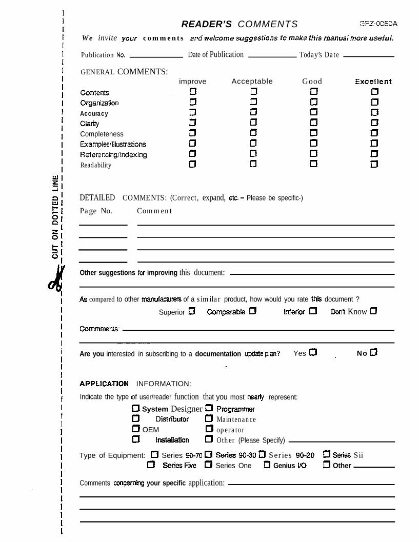
READER’S COMMENTS GFZ-OEM
II1IIIi1IIIIfIfIIII1III
. IIIIII
We invite your comments ard welcome suggestions fo make this manual more useful,
Publication No_ Date of Publication Today’s Date
GENERAL COMMENTS:
Contents
Organization
Accuracy
CtarityCompletenessExamoies/lItustr~tionsReferincingilndexingReadability
improve Acceptable
DETAILED COMMENTS: (Correct, expand, etc_ - Please be specific-)
Page No. Comment
Goodu0uI3u0u17
Other suggestions for improving this document:
As compared to other manufacturers of a similar product, how would you rate this document ?
Superior I3 Comparable 0 Inferior 0 DonY Know m
COITKXTRnts:
Are you interested in subscribing to a documentation update plan? Yes I31 . No 11
APPLfCATiON
Indicate the type of user/reader function that you most nearly represent:
t System Designer a PrOgramn?erm Distriiutor 0 Maintenancea OEM 17 operatorIU Installation U Other (Please Specify)
Type of Equipment: 0 Series %I-70 a Series 90-30 m Series 90-20 0 Series Siifl SeriesFive 0 Series One 13 Genius UO c1 Other
INFORMATION:
Comments concern-bg your specific application:.
1
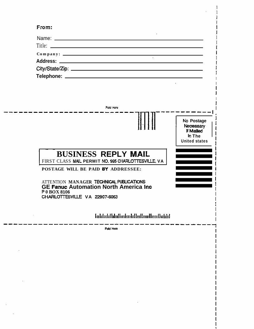
IFROM: I
. IName: I
Title: I1
Company: I.
Address:. I
ICity/State/zip: f
Telephone:II
_ I
1III
Fokf 3ere I-----~~-~~~-~~---_~--~~~~-
mn
~----~-~~~- I
.No Postage
I N===vifM&kd
In TheUnited states
6
IIffIIIII1IIIIIIIIIII
I ~- -~~-
BUSINESS REPLY MAILFIRST CLASS MAIL PERMIT NO- 995 CHARLOTlESVIUE, VAPOSTAGE WILL BE PAID BY ADDRESSEE:
ATTENTION MANAGER TECHNtCAL PUBLlCATK>NSGE Fariuc Automation North America incP 0 BOX 8106CHARLWIESVCUE VA 22907-6063
Contents V
GFK-0075
CHAPTER 1.
Section 1.
Section 2.
Section 3.
CHAPTER 2. OPERATIONSection 1. Using DOS
Versions of DOS
CONTENTS
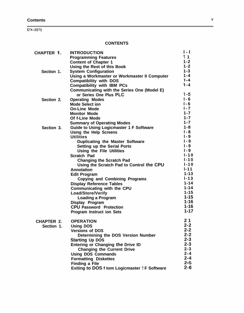
INTRODUCTIONProgramming FeaturesContent of Chapter 1Using the Rest of this BookSystem ConfigurationUsing a Workmaster or Workmaster II ComputerCompatibility with DOSCompatibility with IBM PCsCommunicating with the Series One (Model E)
or Series One Plus PLCOperating ModesMode Select ionOn-Line ModeMonitor ModeOf f-Line ModeSummary of Operating ModesGuide to Using Logicmaster 1 F SoftwareUsing the Help ScreensUtilities
Duplicating the Master SoftwareSetting up the Serial PortsUsing the File Utilities
Scratch PadChanging the Scratch PadUsing the Scratch Pad to Control the CPU
AnnotationEdit Program
Copying and Combining ProgramsDisplay Reference TablesCommunicating with the CPULoad/Store/Verify
Loading a ProgramDisplay ProgramCPU Password ProtectionProgram Instruct ion Sets
Determining the DOS Version NumberStarting Up DOSEntering or Changing the Drive ID
Changing the Current DriveUsing DOS CommandsFormatting DiskettesFinding a FileExiting to DOS f tom Logicmaster 1 F Software
l - l-I 11-21-21-31-41-4114
l-5l - 6l - 6l - 71-71-71-71-8l - 8l - 9l - 9l - 9l - 9l - 1 0l - 1 0l - 1 0l-111-13l -131-141-141-151-151-161-161-17
2 12-22-22-22-32-32-32-42-42-5216
vi Contents
GFK-0075
CONTENTS
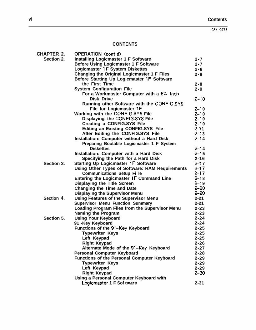
CHAPTER 2. OPERATION (cont’d)Section 2. installing Logicmaster 1 F Software
Before Using Logicmaster 1 F SoftwareLogicmaster 1 F System DiskettesChanging the Original Logicmaster 1 F FilesBefore Starting Up Logicmaster 1F Software
the First TimeSystem Configuration File
For a Workmaster Computer with a 5%~InchDisk Drive
Running other Software with the CONFIG.SYSFile for Logicmaster 1F
Working with the CONFIG.SYS FileDisplaying the CONFIG.SYS FileCreating a CONFIG.SYS FileEditing an Existing CONFIG.SYS FileAfter Editing the CONFIG.SYS File
Installation: Computer without a Hard DiskPreparing Bootable Logicmaster 1 F System
Diskettes.
Installation: Computer with a Hard DiskSpecifying the Path for a Hard Disk
Section 3. Starting Up Logicmaster 1F SoftwareUsing Other Types of Software: RAM Requirements
Communications Setup Fi leEntering the Logicmaster 1F Command LineDisplaying the Title ScreenChanging the Time and DateDisplaying the Supervisor Menu
Section 4. Using Features of the Supervisor MenuSupervisor Menu Function SummaryLoading Program Files from the Supervisor MenuNaming the Program
Section 5. Using Your Keyboard91 -Key KeyboardFunctions of the 91.Key Keyboard
Typewriter KeysLeft KeypadRight KeypadAlternate Mode of the 91.Key Keyboard
Personal Computer KeyboardFunctions of the Personal Computer Keyboard
Typewriter KeysLeft KeypadRight Keypad
Using a Personal Computer Keyboard withlogicmaster 1 F Sof hare
2-72-72-82-8
2-82-9
2-10
2-l 02-l 02-l 02-l 02-l 12-l 32-l 4
2-l 42-l 52-162-l 72-l 72-l 72-l 82-l 92-202-202-212-212-232-232-242-242-252-252-252-262-272-282-292-292-292-30
2-31
Contents vii
GFK-0075
CHAPTER 2.Sect ion 5.
Sect ion 6.
Sect ion 7.
CHAPTER 3.Section 1.
Sect ion 2.
CONTENTS
OPERATION (cont’d)Alt Key Functions
In All ModesSupervisor MenuDisplay Program ModeEdit Program ModeTeach ModeAlternate Keys
Defining Sequences of Frequently-UsedKeystrokes (Teach Mode)
Creating a Customized Key FunctionUsing a Defined Key FunctionDisplaying and Printing a Defined Key Function
(View Mode)Ending the View Mode Display
Entering DataFormat of the DisplayFunction Key AssignmentsStatus Line
Status Line: DefinitionsWork Area
Working With NumbersBinary DataBytesRegisters and WordsDecimalHexadecimalBinary Coded Decimal
SCRATCH PADScratch Pad DisplayAccessing the Scratch Pad Display Screen
On-Line or Monitor ModeOff-Line Mode
Setting System Mode without the KeyswitchScratch Pad Display: DefinitionsEditing the Scratch Pad DisplayWhen the Scratch Pad can be ChangedFunction Key AssignmentsChanging the Entry’for CPU StatusChanging the Entry for Memory SizeChanging the Entry for Function SetChanging tb Entry for Registers
2-322-322-322-322-322-332-33
2-342-342-35
2-352-362-372-372-382-382-382-392-402-402-402-402-412-422-43
3 13-23-23-23-43-53-53-73-73-73-83-83-83-8
. . .VIII Contents
GFK-0075
CHAPTER 4.Section 1.
Sect ion 2.
Sect ion 3.
CHAPTER 5.Section 1.
Sect ion 2.
CONTENTS
DISPLAY PROGRAMDisplaying a ProgramHow to Display a ProgramProgram Display FormatDisplay Program Function Key AssignmentsReturning to the Supervisor MenuGoing to the Reference Tables DisplaySelecting a Rung for DisplayMoving the CursorMoving the Display Up or DownSearching for a Program ElementExecuting a Search
Wildcard Nickname SearchSearch Keys: DefinitionsReturning to the Display Function MenuSearching for the Cause of a Double Left RailMaking On-Line Changes in the ProgramEffect of On-Line ChangesSystem Status Requirement for On-Line ChangesMaking On-Line Changes
Changing a ConstantChanging the Content of a Numeric Field
EDIT PROGRAMEntering Edit Program ModeStarting a New ProgramDisplaying an Existing Program for EditingCreating a Backup ProgramAborting an Edit SessionEditing the ProgramDisplaying a Program in Edit ModeEdit Program Function Key AssignmentsReturning to the Supervisor MenuDisplaying a Specified RungInserting a RungEditing a RungDeleting One or More Program RungsReference Substitution in a Program
Replacing the Same Reference Type in aProgram
Replacing a Reference Type with AnotherReference Type
4 - l4-24-24-44-54-54-64-64-64-64-74 -74-84-84-94-94-104-104-114-114-124-12
5 - l5-25-25-35-45-45-55-55-65-65-75-75-75-75-8
5-8
5-9
Contents ix
GFK-0075
CHAPTER 5. EDIT PROGRAM (cont’d)Sect ion 3. Editing a Rung
Accessing the Edit FunctionsEntering a ReferenceAdding an Open Space to a RungExiting a Rung
Section 4.
Section 5.
CHAPTER 6.Section 1.Sect ion 2.
CONTENTS
Adding a Relay to the ProgramAdding a Coil to the ProgramAdding Arithmetic Functions to the ProgramAdding Data Move Instructions to the ProgramAdding a Timer or Counter to the ProgramAdding Logic Functions to the ProgramAdding Special Instructions to the ProgramSearching for a Program ElementExecuting a Search
Wildcard Nickname SearchSearch Keys: DefinitionsReturning to the Display Function MenuSearching for a “Bad Opcode”Ladder Diagram File EditingCopying Rungs to a Side (.SDE) FileAdding a .SDE or .LAD to a Program
ANNOTATIONTypes of AnnotationEntering and Editing AnnotationAccessing the Annotation Editing FunctionsEdit Comment Function KeysUsing Annotation in a ProgramLoading the ProgramCreating an Annotation FileEntering Nicknames When Creating a RungDeleting a NicknameEntering Annotation in Window Mode or Page
ModeEditing Annotation in Window Mode
Entering a Rung Explanation in Window ModeEntering a Coil Label in Window ModeEditing Names in Window Mode
Editing Annotation in Page ModeEntering a Rung Explanation in Page ModeEntering a Coil Label in Page ModeEditing a Name or Nickname in Page Mode
Annotation Text EditingText Editing Instructions
Creating Additional Text Files for AnnotationPrintout
Renumbering Rung Explanations
5-105-l 05-l 15-l 15-l 15-l 25-l 35-155-l 75-l 85-l 95-215-235-235-245-245-255-255-265-265-27
6 - l6-26-36-36-46-46-46-56-56-5
6-66-66-66-76-76-76-86-86-96-96-9
6-l 16-11
X Contents
UK-0075
CHAPTER 6.Section 3.
Sect ion 4.
CHAPTER 7.Section 1.
Sect ion 2.
Section 3.
Sect ion 4.
Sect ion 5.
CONTENTS
ANNOTATION (cont’d)Viewing Annotation in Display Program ModeAccessing the Annotation Display FunctionsDisplay Comment FunctionsPrinting AnnotationSetting up the PrinterChanging the Title on the PrintoutPlacing Borders Around Comments in Printouts
DISPLAY REFERENCE TABLESUsing the Display Reference Tables FunctionHow to Display the Reference TablesMoving within a Reference TableMoving From One Reference Table to AnotherReturning to the Supervisor MenuReturning to the Ladder Diagram DisplayOff-Line Display of Reference TablesOn-Line Display of Reference TablesDisplaying Discrete ReferencesDisplaying a Table of Discrete Referencesi/O, Internal Coil, Shift Register, T/C Up
Status TableFormat of the Discrete Reference DisplayDiscrete Reference Tables Function KeysReturning to the Supervisor MenuReturning to the Ladder Diagram DisplayDisplaying Data Register ContentsDisplaying a Table of Register ReferencesData Register TableFormat of the Data Register Reference DisplayRegister Reference Tables Function KeysDisplaying Accumulate Register ContentsDisplaying a Table of Register ReferencesTimer/Counter Accumulate TableFormat of the Accumulate Register Reference
DisplayRegister Reference Tables Function KeysMaking On-Line ChangesEffect of On-Line ChangesMaking On-Line Changes
Forcing the Status of a ReferenceChanging the Value of a Register of Discrete
ReferenceChanging Register Values
6-136-136-146-156-156-176-17
7 - I7-27-27-27-37-37-37-37-37-47-4
7-S7-57 -67 -67-67-77 -77 -77 -87-87 -97 -97-9
7-107-107-117-l-l7-127-12
7-137-13
Contents xi
GFK-0075
CHAPTER 8.
Section 1.
Sect ion 2.
Section 3.
Sect ion 4.
Sect ion 5.
CHAPTER 9.Section 1.
Sect ion 2.
Sect ion 3.
Sect ion 4.
Sect ion 5.
CONTENTS
PRINTPrinting a Copy of the ScreenThe Print MenuDisplaying the Print MenuPrint Menu Function Key SummarySetting Up the PrinterAttaching Your Printer to the System
Parallel PrinterSerial Printer
Defining the Printer ParametersChanging the Entries on the Printer
Parameters ScreenPrinter Parameters: DefinitionsDefining the Print-Out ContentDisplaying the Define Print-Out Content ScreenChanging the Entries on the Print-Out Content
ScreenDefine Print-Out Content Screen: DefinitionsPrinting in Foreground ModeDisplaying the Print to Disk or Printer MenuPrinting in Foreground ModeCreating a Print FileStopping a Print-Out TemporarilyCanceling a Print-OutPrinting a File in Background ModeBackground PrintingDisplaying the Print Program MenuEnter the Destination and Program NameStopping a Pr in&Out
LOAD/STOREAIERIFYThe Load/Store/Verify MenuDisplaying the Load/Store/Verify MenuLoad/Store/Verify Menu Function Key SummaryLoading a Program into Programmer MemoryDisplaying the Load Program ScreenLoading a Program into the System From a DiskLoading a Program into the System From a CPUCanceling the Load FunctionStoring Data From Programmer MemoryDisplaying the Store Program ScreenStoring a Pragram PO a DiskStoring a Program to the CPUCaeIing the Store FunctionVerifying the Content of Program DataDisplaying the Verify Program MenuVerifying Program Data
Verify Miscompare ScreenClearing Programmer Memory
8 - l8 18-28-28-28-38-38-38-48-5
8-58-68-88-8
8-98-98-188-188-198-198-208-208-218-21
- 8-218-228-22
9-l9-29-29-39-49-49-59-59-59-69-69-79-79-89-99-99-109-l 19-l 2
xii Contents
CHAPTER 10.Section 1.
Sect ion 2.
Section 3.
Sect ion 4.
CHAPTER 11.Section 1.
Sect ion 2.
Section 3.
Sect ion 4.
CONTENTS
CONFIGURATION SETUP 1 O-lThe Configuration Setup Menu 10-2Displaying the Configuration Setup Menu 1 o-2Configuration Setup Menu 1 o-2Setting Up Communications with the CPU 10-3Displaying the Communications Setup Menu 10-3Changing the Communications Setup Screen 10-4
Cancel ing Entries on the CommunicationsSetup Screen
Communications Setup Screen: DefinitionsRecovering from an Error in the CPUCPU Password ProtectionDisplaying the CPU Password Protection MenuCPU Password Protection Key SummaryUnlocking the CPULocking the CPUChanging the PasswordThe Machine Setup MenuDisplaying the Machine Setup MenuMachine Setup Key SummaryChanging Screen Colors
10-410-410-610-71 o-71 o-71 O-81 o-91 o-910-1010-1010-1010-11
UTILITIESThe Utilities MenuDisplaying the Utilities MenuU t i I it ies Function Key SummaryDuplicating the Master SoftwareUsing the Duplicate Master Software Utility:
Diskette SystemSingle Diskette Drive SystemMultiple Diskette Drive SystemHard Disk System
Using the File UtilitiesFile Names
11-l11-211-211-211-3
Reserved File NamesUsing ‘*Wildcards*’ to Represent Parts of
File NamesProgram Files
11-311-411-511-611-711-711-7
Other Files of InterestCopying FilesRenaming Backup FilesDeleting Program FilesDisplaying and Printing a Directory of Files
Ccwrtr&ing the Scroll of File NamesEnding the Directory Utility
Setting Up the Serial PortsDisplaying the Port Setup ScreenPort Setup Screen Key SummaryDisplaying the Current Parameters for a PortDisplaying Parameters in a Port Setup FileSetting up Port Parameters
11-711-811-911-911-1111-1211-1311-1411-1411-1511-1511-1611-1611-1611-16
GFK-0075
Contents. . .
XIII
GFK-0075
CHAPTER 12.Section I.
Sect ion 2.
. Thumbwheel CounterHigh Speed CounterShift Register
CHAPTER 13. DATA OPERATION INSTRUCTIONS FOR THE
Section 1.
Section 2.
CONTENTS
PROGRAMMINGLadder Logic ProgramsHow the CPU Executes a programBasic Ladder Diagram FormatElements of a Ladder DiagramUsing the Edit Program Function to Create
ProgramsFormat of a Ladder Diagram FunctionReferencesProgramming Instruct ionsNormally Open ContactNormally Closed ContactShunt/OpenVert/OpenSequencer Normally Open .Sequencer Normally ClosedMaster Control Start (KS)Master Control Reset (MCR)Relay Coi ISet CoilReset Coi ISet Out CoilSet Out Reset Coil (One Shot)TimerThumbwheel TimerCounter
SERIES ONE PLUS PLCData OperationsUsing References for Data Operations
Entering a Constant ValueEntering a Group Reference
Data Register ReferencesTimer/Counter References
Specifying a Group ReferenceSpecial Function Coi isData Move OperationsData Store 0 (Function 50)Data Store 1 (Function 51)Data Store 2 (Function 52)Data Store 3 (Function 53)Data Store 5 (Function 55)Data Out 0 (Function 60)Data Out 1 (Function 61)Data Out 2 (Function 62)Data Out 3 (Function 63)Data Out 5 (Function 65)External Fault Diagnostics (Function 20)
12-l12-Z12-212-312-4
12-612-712-812-912-1212-1312-1412-1512-1612-1712-1812-1912-2012-2112-2212-2312-2412-2512-2612-2712-2812-2912-30
13-I13-213-313-313-313-413-413-413-513-613-813-913-1013-1113-1213-1313-1413-1513-1613-1713-18
xiv Contents
CHAPTER 13.
Sect ion 3.
Sect ion 4.
Appendix A.B .C .D .E .F .
GFK-0075
CONTENTS
DATA OPERATION INSTRUCTIONS FOR THESERIES ONE PLUS PLC
Arithmetic OperationsCompare (Function 70)Add (Function 71)Subtract (Function 72)Multiply (Function 73)Divide (Function 74)Logic OperationsData AND (Function 75)Data OR (Function 76)Shift Right (Function 80)Shift Left (Function 81)Decode (Function 82)Encode (Function 83)Invert (Function 84)BCD to Binary (Function 85)Binary to BCD (Function 86)
APPENDIXES
Setup InformationGlossary of TermsTranslator Keyboard ChartSoftware Function Key Flow DiagramsLogicmaster 1 Software PackageLaicmaster 1 Junior Software Package
1 3 - l13-1913-2113-2313-2513-2713-2913-3113-3313-3513-3713-3813-3913-4013-4113-4213-43
A - lBlc-1D-1E- lF - l
Contents xv
Figure 2.12 2.2 3.2 4.2 5.61.6 2.81
12’112’212.313’1.01D’2D’3Do4D’SD-6D’7D’8Do9.
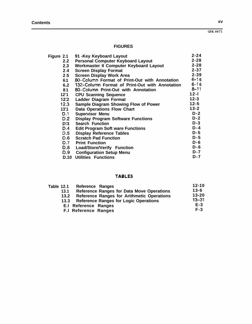
FIGURES
91 -Key Keyboard LayoutPersonal Computer Keyboard LayoutWorkmaster II Computer Keyboard LayoutScreen Display FormatScreen Display Work Area80-Column Format of Print-Out with Annotation132.Column Format of Print-Out with Annotation80.Column Print-Out with AnnotationCPU Scanning SequenceLadder Diagram FormatSample Diagram Showing Flow of PowerData Operations Flow ChartSupervisor MenuDisplay Program Software FunctionsSearch FunctionEdit Program Soft ware FunctionsDisplay Reference TablesScratch Pad FunctionPrint FunctionLoad/Store/Verify FunctionConfiguration Setup Menu
D.10 Utilities Functions
TASLES
Table 12.1 Reference Ranges 12-1013.1 Reference Ranges for Data Move Operations 13-613.2 Reference Ranges for Arithmetic Operations 13-2013.3 Reference Ranges for Logic Operations 13-31E.l Reference Ranges E-3F.l Reference Ranges F-3
GFK-0075
2-242-282-282-372-396-l 66-l 68-l 1
12- l12-312-513-2
D-2D-2D-3D-4D-5D-5D-6D-6D-7D-7

Introduction l - l
CHAPTER 1INTRODUCTION
The Logicmast@” 1 F Programming and Documentation Software packages from GEFanuc Automation North America, inc. are used to create ladder logic programs for theSeries One family of programmable logic controllers (PLCs). Program development maybe done on a Workmaster@, Workmaster II, or CimstarTn I industrial computer, an IBMPC, PC-XT, or PC-AT, or most IBM-compatible personal computers.
The Workmaster, Workmaster Ii, and Cimstar I computers are industrial-hardenedcomputers: recommended for installations where programs must be transferred,monitored, or edited in the harsh conditions of the factory floor. The Workmaster andWorkmaster II computers have the additional important advantage of easy portability.
The 91.key keyboard from GE Fanuc - NA was designed to satisfy the specialrequirements of PLC programming and monitoring. Refer to section 5 in chapter 2 for anexplanation of the functions of the 91.key keyboard. Section 5 also describes the use of astandard IBM personal computer-type keyboard with Logicmaster 1 F software. Althoughsuch a keyboard lacks the additional programming keys of the 91.key keyboard, it can beused with Logicmaster 1 F software by referring to the table on page 2-31.
After a program is developed, it is simple to transfer it to either the Series One (Model E)CPU (IC610CPU104A) or the Series One Plus CPU (IC61OCPUlOSA or lC61OCPU106A).Then, the Logicmaster 1F system can be used on-line with one or more operating CPUs,to provide continuously-updated displays of reference tables and program logic. ThP,logic display features symbolic power flow through the rungs, so program execution canbe traced.
This manual describes the Logicmaster 1 Family software package to be used with eitherthe Series One (Model E) or Series One Plus PLC. Programming and documentationsoftware is also available for the Series One and Series One Junior PLCs. For the mostpart, this manual applies to those software packages as well. Where differences do exist,they have been described in Appendix E for the Logicmaster 1 software package andAppendix F for the Logicmaster 1 Junior software package.
PROGRAMMING FEATURES
Logicmaster 1F software offers a full range of programming functions, such as:
0 Basic contacts, coils, timers, and counters.
0 Extensive, easy-to-display Help files-
0 Printout of display screens, programs, annotation, and tables.
0 Program storage on diskettes or hard disk.
a The ability to combine part or all of one ladder logic program with another.
0 On-line monitoring and change.
l - 2 Introduction
GFK-0075
CONTENT OF CHAPTER 1
Chapter 1 contains the following sections:
Section I. System Configuration: Section 1 lists the versions of Logicmaster 1Fsoftware that are available, and gives their hardware requirements and characteristics.
Section 2. Operating Modes: Section 2 describes the Logicmaster 1F system’s threedifferent modes of operation.
Section 3. Guide to Using Logicmaster 1Ft Section 3 contains brief descriptions of ailthe principal features of the Logicmaster 1F software. If you have not used Logicmastersoftware before, you should read this section. The individual topics contain referencesthat will guide you through the rest of the text.
USING THE REST OF THIS BOOK
The rest of this book is arranged as a reference to the features of Logicmaster 1Fsoftware. Chapters 3 through 11 are about Logicmaster 1F software. Chapters 12 and 13are about creating ladder logic programs. After reading the Introduction, you can referto other chapters as you need them. For example:
0 When you are starting up the software, refer to chapter 2 for instructions.
0 If you are editing a ladder logic program, you can refer to chapter 5 for generalediting informat ion.
0 Chapters 12 and 13 contain descriptions of all the basic programming instructionsand data operation instruct ions.
0 Appendix E describes the Logicmaster 1 software package.
0 Appendix F describes the Logicmaster I Junior software package.
Each chapter or appendix contains related information about one aspect of programmingor operating Logicmaster 1F software. To locate a major subject area, refer to the tableof contents. To locate specific information about individual topics, refer to the index atthe end of the book.
Introduction
GFK-OC)75
l - 3
SECTION 1SYSTEM CONFIGURATION
This section describes the two versions of Logicmaster 1F software that are available. Italso describes the general hardware configuration required for each version.
The two versions are:
0 A 3’!&inch version for the Workmaster, Workmaster II, or Cimstar I industrialcomputer, or for any other 3%~inch disk drive-based personal computer with theappropriate hardware.
0 A V/L-inch version for use on an IBM personal computer (PC), IBM PC-XT, or IBMPC-AT, or most IBM-compatible personal computers. In this book, when we use theterm IBM PC, the information also applies to the PC-XT, PC-AT, a n dIBM-compatible PC, unless otherwise indicated. Note that operation withcompatibles is not assured.
While programs are under development, both versions are functionally similar. With acompleted program transferred to a Series One (Model E) or Series One Pius CPU, bothversions can be used to monitor program execution and communicate certain operatorchanges to the program. Both versions feature:
a Operation on a system having any combination of one to four floppy-diskette drives,and/or one or two hard disk drives.
0 Support of the Enhanced Graphics Adapter (EGA) card.
l - 4 Introduction
GFK-0075
USING A WORKMASTER OR WORKMASTER II COMPUTER
To run the Logicmaster 1 F software, the Workmaster or Workmaster Ii computer musthave the following:
0 640K total available programmer memory (RAM).
0 The correct version of DOS. For more information about DOS, refer to chapter 2,Operation.
It is advisable for additional printed circuit boards in the computer to be removed. Forexample, if the Workmaster computer has been used as part of a VuMasterTn system, thegraphics board should be removed. Refer to GEK-25373, Workmaster Guide toOperations, for instructions before you disassemble the computer.
COMPATIBILITY WITH DOS
To run togicmaster 1F software, the host computer requires GE-DOS version 1(equivalent to MS-DOS 3.2). For a hard disk system, this DOS version should be copied tothe hard disk, as described in chapter 2.
NOTE
DOS must be ordered separately.
COMPATIBILITY WITH IBM PCs
Logicmaster 1F software can be used on an IBM-PC, PC-XT, PC-AT, or mostIBM-compatible personal computers with the following characteristics:
0 640K total available programmer memory (RAM).
0 The correct version of PC-DOS:
- Version 2.1 or 3.1 for the IBM-PC and PC-XT.
- Version 3.1 or 3.2 for the IBM PC-AT.
- Version 3.3 or 4.0 for the IBM Personal System/2@ computer.
0 Either a color or monochrome monitor adapter card. The software will also supportthe Enhanced Graphics Adapter (EGA) card.
Performance of the software with other versions of DOS is not guaranteed. Neither isperformance guaranteed on other types of IBM PC-compatible computers.
The system supports the IBM monochrome adapter board and the asynchronouscommunications adapter board. It does not support serial communications adapters notbased on the 8250 UART.
An IBM PC-based Logicmaster 1 F system communicates with the Series One (Model E) orSeries One Plus PLC via the serial ports, to the Data Communications Unit (DCU) in theCPU.
introduction l - 5
GFK-0075
COMMUNICATING WITH THE SERIES ONE (MODEL E) OR SERIES ONE PLUS PLC
Logicmaster 1F software communicates with the Series One (Model E) or Series One PlusPLC over a serial communications channel to a Data Communications Unit (DCU).Communication is possible over long distances, using a wide range of baud rates, with orwithout modems. The system can communicate with a single DCU and CPU, or be used ina multidrop configuration having up to eight DCUs and CPUs.
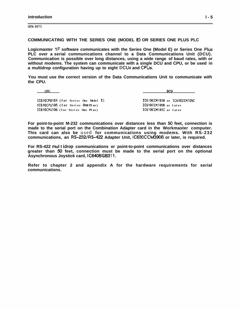
You must use the correct version of the Data Communications Unit to communicate withthe CPU.
CPU DCU
IC61OCPU104 (for Series One Model E)ICdlOCPU105 (for Series One Plus)IC61OCPU106 (for Series One Plus)
IC610CCM105B or IC610CCM105CIC6lOCCMlOSB or laterIC6lOCCMlOSC or later
For point-to-point M-232 communications over distances less than 50 feet, connection ismade to the serial port on the Combination Adapter card in the Workmaster computer.This card can also be used for communications using modems. With RS-232communications, an RS-232/R%422 Adapter Unit, IC630CCM3906 or later, is required.
For RS-422 mul t idrop communications or point-to-point communications over distancesgreater than 50 feet, connection must be made to the serial port on the optionalAsynchronous Joystick card, iC640BGB311.
Refer to chapter 2 and appendix A for the hardware requirements for serialcommunications.
l - 6 Introduction
GFK-0075
SECTION 2OPERATING MODES
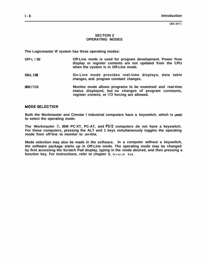
The Logicmaster IF system has three operating modes:
OFF-L I NE Off-Line mode is used for program development. Power flowdisplay or register contents are not updated from the CPUwhen the system is in Off-Line mode.
ON-L I NE
MON I TOR
On-Line mode provides real-time displays, data tablechanges, and. program constant changes.
Monitor mode allows programs to be examined and real-timestatus displayed, but no changes of program constants,register content, or I/O forcing are allowed.
Both the Workmaster and Cimstar I industrial computers have a keyswitch, which is usedto select the operating mode.
The Workmaster II, IBM PC-XT, PC-AT, and PSI2 computers do not have a keyswitch.For these computers, pressing the ALT and 1 keys simultaneously toggles the operatingmode from off-line to monitor to on-line.
Mode selection may also be made in the software. In a computer without a keyswitch,the software package starts up in Off-Line mode. The operating mode may be changedby first accessing the Scratch Pad display, typing in the mode desired, and then pressing afunction key. For instructions, refer to chapter 3, Scratch Pad.
Introduction l - 7
GFK-0075
ON-LINE MODE
In On-Line mode with the CPU unlocked, the CPU periodically sends an updated input andoutvut status table, register memory, and Scratch Pad to the Logicmaster 1F system.On-line changes can be made to register data values and program constants, and to toggleinputs or outputs that are currently in the CPU. For more information, refer to chapter4, Display Program, and chapter 5, Edit Program.
MONITOR MODE
In Monitor mode with the CPU unlocked, the system can read data from the CPU, butmay not transfer data to the CPU. All registers and tables are updated automatically toreflect the current operating state of the CPU. For Workmaster and Cimstar Icomputers, this is the only operating mode that allows removal of the key from the unit’skeysw i tch.
OFF-LINE MODE
In Off-Line mode, tables and registers are updated in the programmer memory (not theCPU) only upon command from the keyboard. Programs may conveniently be developedin Off-Line mode, without being connected to a CPU.
SUMMARY OF OPERATING MODES
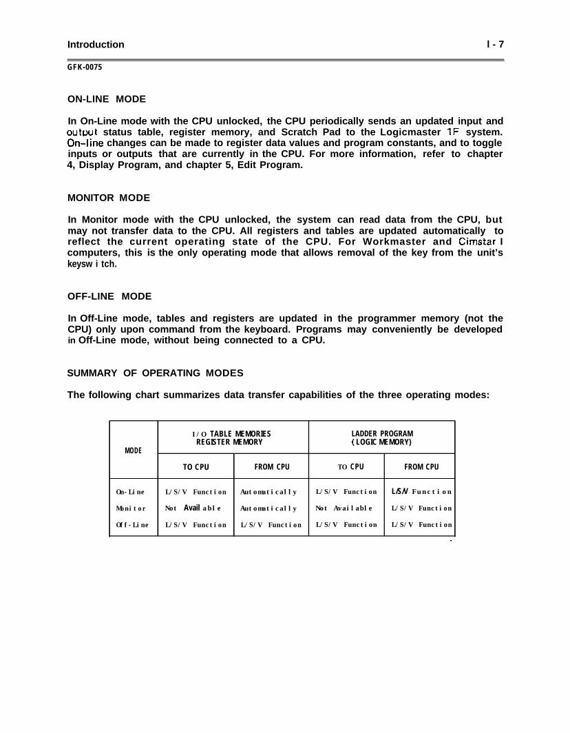
The following chart summarizes data transfer capabilities of the three operating modes:
I/O TABLE MEMORIES LADDER PROGRAMREGISTER MEMORY ( LOGIC MEMORY)
MODE
TO CPU FROM CPU TO CPU FROM CPU
On-Line L/S/V Function Automatically L/S/V Function L/S/V Function
Monitor Not Avail able Automatically Not Available L/S/V Function
Off-Line L/S/V Function L/S/V Function L/S/V Function L/S/V Function
.
l - 8 Introduction
GFK-0075
SECTION 3GUIDE TO USING LOGICMASTER 1 F SOFTWARE
This section introduces many of the features of Logicmaster 1 F software. Individualtopics include references to guide you to other chapters in the book, where more detailedinformation is located.
Section 3 introduces these subjects:
How to duplicate the master software, set up serial ports, and handle files.
How to use the Scratch Pad function to set up programming parameters, or to turnthe CPU on and off.
The types of program annotation you can include in a program.
How to edit, copy, and combine ladder logic programs.
HOW to display tables of register and I/O values.
How the software is set up to communicate with the Series One (Model E) CPU orthe Series One Plus CPU.
How to transfer programs between the computer and the CPU, and between thecomputer and disks.
The format of ladder logic, and how to display a program.
How to enter a password.
USING THE HELP SCREENS
Logicmaster 1 F software includes detailed Help screens. For more information about thefeature you are using, just press the Help key on your keyboard. The Help screens areeasy to get into of out of. Program data will not be lost if you press the Help key. Youwill find the Help screens to be a very useful feature of Logicmaster 1F software.
The Help screens are always available when the diskette containing them is present in thecomputer. For a system with hard disk memory storage, the Help files can be loaded ontothe hard disk.
Introduction l - 9
GFK-0075
UTILITIES
The Utilities functions are probably the first functions you will use.
Duplicating the Master Software
When you start up the system for the first time, you will use the original diskettesshipped from the factory. You should make copies of these diskettes. If you have afloppy diskette system, copying the master diskettes will give you a set of diskettes foreveryday use. If you have a hard disk system, copying the master diskettes will placeLogicmaster 1 F software on the hard disk. Chapter 11, Utilities, explains how to copyyour master diskettes.
Setting up the Serial Ports
The Serial Port Setup utility is used to select the characteristics for serial ports. Youmust do this for the system to be able to communicate with the CPU. If you have a serialprinter or other device, you will use the Serial Port Setup utility before using the printer.Refer to chapter 11 for instructions.
Using the File Utilities
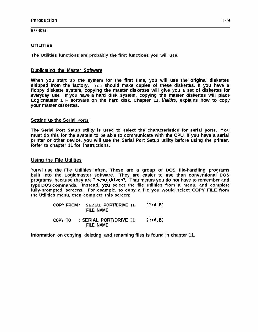
You will use the File Utilities often. These are a group of DOS file-handling programsbuilt into the Logicmaster software. They are easier to use than conventional DOSprograms, because they are ttmenu-driventt. That means you do not have to remember andtype DOS commands. Instead, you select the file utilities from a menu, and completefully-prompted screens. For example, to copy a file you would select COPY FILE fromthe Utilities menu, then complete this screen:
COPY FROM : SERIAL PORT/DRIVE ID (l/A,B>FILE NAME
COPY TO : SERIAL PORT/DRIVE ID (l/A,B)FILE NAME
Information on copying, deleting, and renaming files is found in chapter 11.
l-10 Introduction
GFK-0075
SCRATCH PAD
The Logicmaster 1F system can easily be used to create programs off-line, perhaps in alocation far from the programmable logic controller (PLC). With Logicmaster 1Fsoftware, one computer can be used to create programs for many Series One (Model E) orSeries One Plus PLCs. These programs can be stored on diskettes or a hard disk, and usedwhenever and wherever they are needed.
Logicmaster 1F software can be used to create programs with the features described inthis book. Your PLC may not be able to use all of these features. For instance, you maybe creating programs for several PLCs that have CPUs with different capabilities.
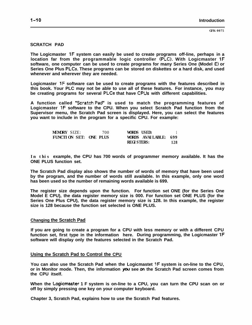
A function called 5cratch Pad” is used to match the programming features ofLogicmaster 1F software to the CPU. When you select Scratch Pad function from theSupervisor menu, the Scratch Pad screen is displayed. Here, you can select the featuresyou want to include in the program for a specific CPU. For example:
MEMORY SIZE: 700 WORDS USED: 1FUNCTION SET: ONE PLUS WORDS AVAILABLE: 699
REGISTERS: 128
In this example, the CPU has 700 words of programmer memory available. It has theONE PLUS function set.
The Scratch Pad display also shows the number of words of memory that have been usedby the program, and the number of words still available. In this example, only one wordhas been used so the number of remaining words available is 699. *
The register size depends upon the function. For function set ONE (for the Series OneModel E CPU), the data register memory size is 000. For function set ONE PLUS (for theSeries One Plus CPU), the data register memory size is 128. In this example, the registersize is 128 because the function set selected is ONE PLUS.
Changing the Scratch Pad
If you are going to create a program for a CPU with less memory or with a different CPUfunction set, first type in the information here. During programming, the Logicmaster 1Fsoftware will display only the features selected in the Scratch Pad.
Using the Scratch Pad to Control the CPU
You can also use the Scratch Pad when the Logicmastet 1F system is on-line to the CPU,or in Monitor mode. Then, the information you see on the Scratch Pad screen comes fromthe CPU itself.
When the Logicmaster 1 F system is on-line to a CPU, you can turn the CPU scan on oroff by simply pressing one key on your computer keyboard.
Chapter 3, Scratch Pad, explains how to use the Scratch Pad features.
Introduction
GFK-0075
I-11
ANNOTATION
Annotation is explanatory text in a program. This text makes a program easier to readand understand.
There are four basic types of annotation:
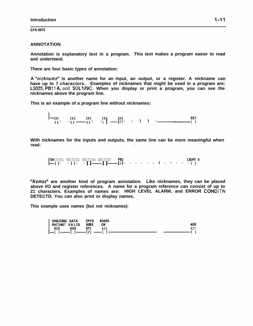
A “nickname” is another name for an input, an output, or a register. A nickname canhave up to 7 characters. Examples of nicknames that might be used in a program are:LSO35, PBll A, and SOL129C. When you display or print a program, you can see thenicknames above the program line.
This is an example of a program line without nicknames:
I-201 202 203 204 205 057II - - II II - - I I VI - - I I - -II( )
With nicknames for the inputs and outputs, the same line can be more meaningful whenread: .
SWITCH1 SWITCH2 SWITCH6 SWITCH7I- PB2 LIGHT 8I I - - I I - - I I I I I/I - - - - - - I - ~ - - - (1
**Names” are another kind of program annotation. Like nicknames, they can be placedabove I/O and register references. A name for a program reference can consist of up to21 characters. Examples of names are: HIGH LEVEL ALARM, and ERROR CONDITNDETECTD. You can also print or display names.
This example uses names (but not nicknames):
ONGOING DATA OPEN BOARDONESHOT V A L I D WIRE OK AOK
025 009 011 013 027
i-12 Introduction
GFK-0075
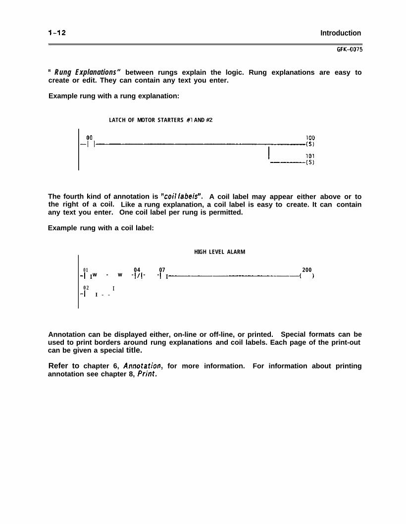
If Rung Explanations” between rungs explain the logic. Rung explanations are easy tocreate or edit. They can contain any text you enter.
Example rung with a rung explanation:
LATCH OF MOTOR STARTERS #I AND #2
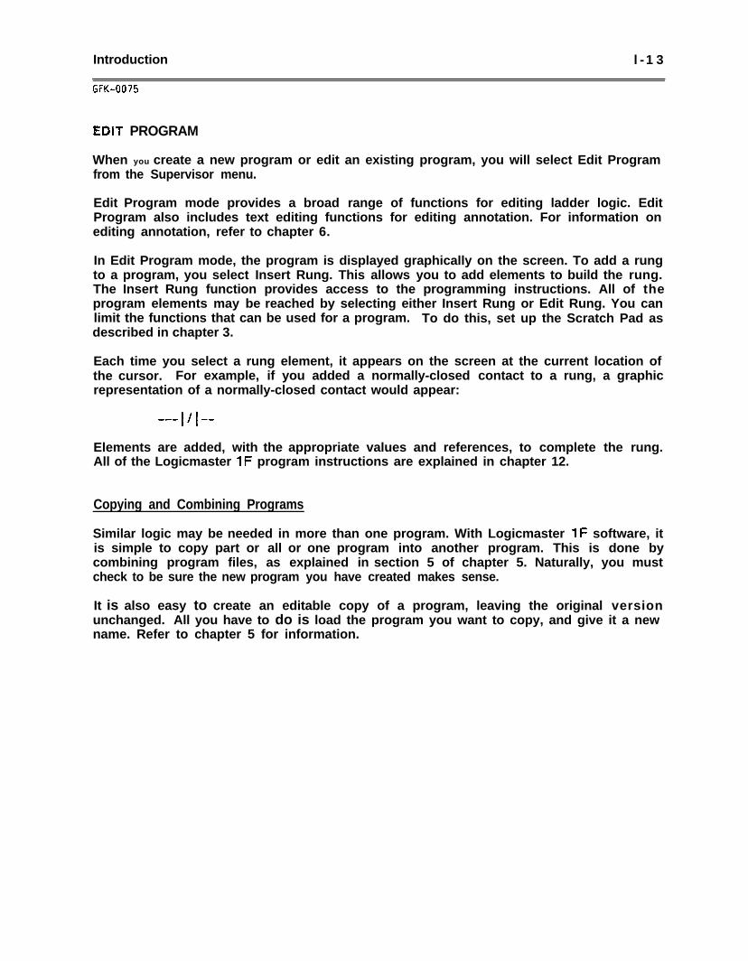
The fourth kind of annotation is Veil /abeW. A coil label may appear either above or tothe right of a coil. Like a rung explanation, a coil label is easy to create. It can containany text you enter. One coil label per rung is permitted.
Example rung with a coil label:
HIGH LEVEL ALARM
01 04 07 200-I I w - w - i/l - - i I~~~~-~--~~~~~-- ( )
02-I I - -
I
Annotation can be displayed either, on-line or off-line, or printed. Special formats can beused to print borders around rung explanations and coil labels. Each page of the print-outcan be given a special title.
Refer to chapter 6, Annotation, for more information. For information about printingannotation see chapter 8, Print.
Introduction l -13
GFK-0075
EDIT PROGRAM
When you create a new program or edit an existing program, you will select Edit Programfrom the Supervisor menu.
Edit Program mode provides a broad range of functions for editing ladder logic. EditProgram also includes text editing functions for editing annotation. For information onediting annotation, refer to chapter 6.
In Edit Program mode, the program is displayed graphically on the screen. To add a rungto a program, you select Insert Rung. This allows you to add elements to build the rung.The Insert Rung function provides access to the programming instructions. All of theprogram elements may be reached by selecting either Insert Rung or Edit Rung. You canlimit the functions that can be used for a program. To do this, set up the Scratch Pad asdescribed in chapter 3.
Each time you select a rung element, it appears on the screen at the current location ofthe cursor. For example, if you added a normally-closed contact to a rung, a graphicrepresentation of a normally-closed contact would appear:
Elements are added, with the appropriate values and references, to complete the rung.All of the Logicmaster 1F program instructions are explained in chapter 12.
Copying and Combining Programs
Similar logic may be needed in more than one program. With Logicmaster 1F software, itis simple to copy part or all or one program into another program. This is done bycombining program files, as explained in section 5 of chapter 5. Naturally, you mustcheck to be sure the new program you have created makes sense.
It is also easy to create an editable copy of a program, leaving the original versionunchanged. All you have to do is load the program you want to copy, and give it a newname. Refer to chapter 5 for information.
l - 1 4 Introduction
GFK-0075
DISPLAY REFERENCE TABLES
The Logicmaster 1 F system maintains a set of tables showing the values of the inputs,outputs, and registers available in the CPU. The reference table you wish to display isselected from the Supervisor menu.
If you make no entry in the work area of the screen, the last table displayed isautomatically selected. If no table has been displayed, then the discrete table is selectedand the cursor will be on I/O point number 0.
You may also enter a reference, reference type, or nickname in the work area. If onlythe type of reference is shown in the work area, the first reference of that type willappear.
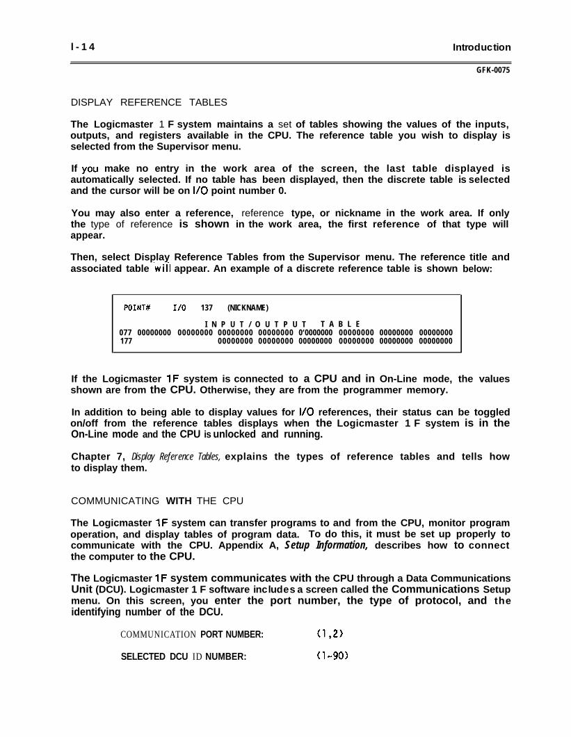
Then, select Display Reference Tables from the Supervisor menu. The reference title andassociated table -wil-I appear. An example of a discrete reference table is shown below:
POINT# I/O 137 (NICKNAME)
I N P U T / O U T P U T T A B L E077 00000000 00000000 00000000 00000000 0‘0000000 00000000 00000000 00000000177 00000000 00000000 00000000 00000000 00000000 00000000
If the Logicmaster 1F system is connected to a CPU and in On-Line mode, the valuesshown are from the CPU. Otherwise, they are from the programmer memory.
In addition to being able to display values for I/O references, their status can be toggledon/off from the reference tables displays when the Logicmaster 1 F system is in theOn-Line mode and the CPU is unlocked and running.
Chapter 7, Display Reference Tables, explains the types of reference tables and tells howto display them.
COMMUNICATING WITH THE CPU
The Logicmaster 1F system can transfer programs to and from the CPU, monitor programoperation, and display tables of program data. To do this, it must be set up properly tocommunicate with the CPU. Appendix A, Setup Information, describes how to connectthe computer to the CPU.
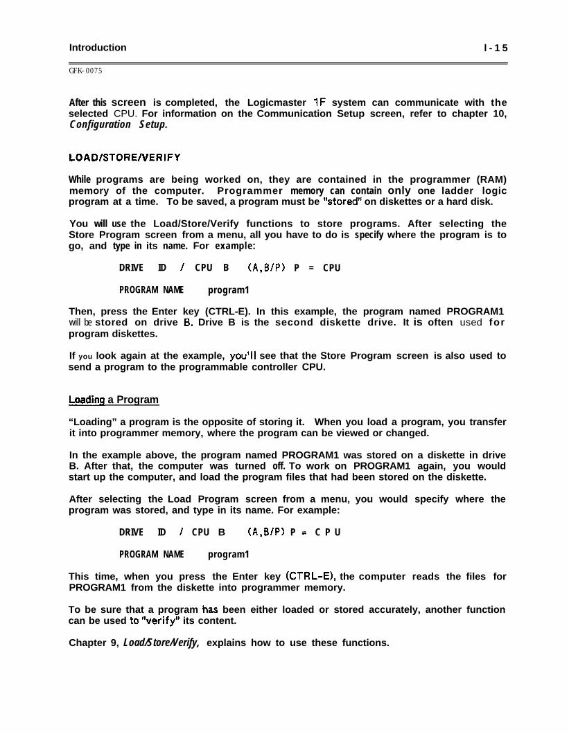
The Logicmaster 1F system communicates with the CPU through a Data CommunicationsUnit (DCU). Logicmaster 1 F software includes a screen called the Communications Setupmenu. On this screen, you enter the port number, the type of protocol, and theidentifying number of the DCU.
COMMUNICATION PORT NUMBER: (1,2)
SELECTED DCU ID NUMBER: (l-90)
Introduction l - 1 5
GFK-0075
After this screen is completed, the Logicmaster 1F system can communicate with theselected CPU. For information on the Communication Setup screen, refer to chapter 10,Configuration Setup.
LOAD/STORENERIFY
While programs are being worked on, they are contained in the programmer (RAM)memory of the computer. Programmer memory can contain only one ladder logicprogram at a time. To be saved, a program must be %tored” on diskettes or a hard disk.
You will use the Load/Store/Verify functions to store programs. After selecting theStore Program screen from a menu, all you have to do is specify where the program is togo, and type in its name. For example:
DRIVE ID / CPU B (A,B/P) P = CPU
PROGRAM NAME program1
Then, press the Enter key (CTRL-E). In this example, the program named PROGRAM1will be stored on drive 8. Drive B is the second diskette drive. It is often used forprogram diskettes.
If you look again at the example, youVl see that the Store Program screen is also used tosend a program to the programmable controller CPU.
Load4 a Program
“Loading” a program is the opposite of storing it. When you load a program, you transferit into programmer memory, where the program can be viewed or changed.
In the example above, the program named PROGRAM1 was stored on a diskette in driveB. After that, the computer was turned off. To work on PROGRAM1 again, you wouldstart up the computer, and load the program files that had been stored on the diskette.
After selecting the Load Program screen from a menu, you would specify where theprogram was stored, and type in its name. For example:
DRIVE ID / CPU B (A,B/P> P = C P U
PROGRAM NAME program1
This time, when you press the Enter key (CTRL-E), the computer reads the files forPROGRAM1 from the diskette into programmer memory.
To be sure that a program has been either loaded or stored accurately, another functioncan be used to “verify” its content.
Chapter 9, Load/Store/Verify, explains how to use these functions.
l-16 Introduction
GFK-0075
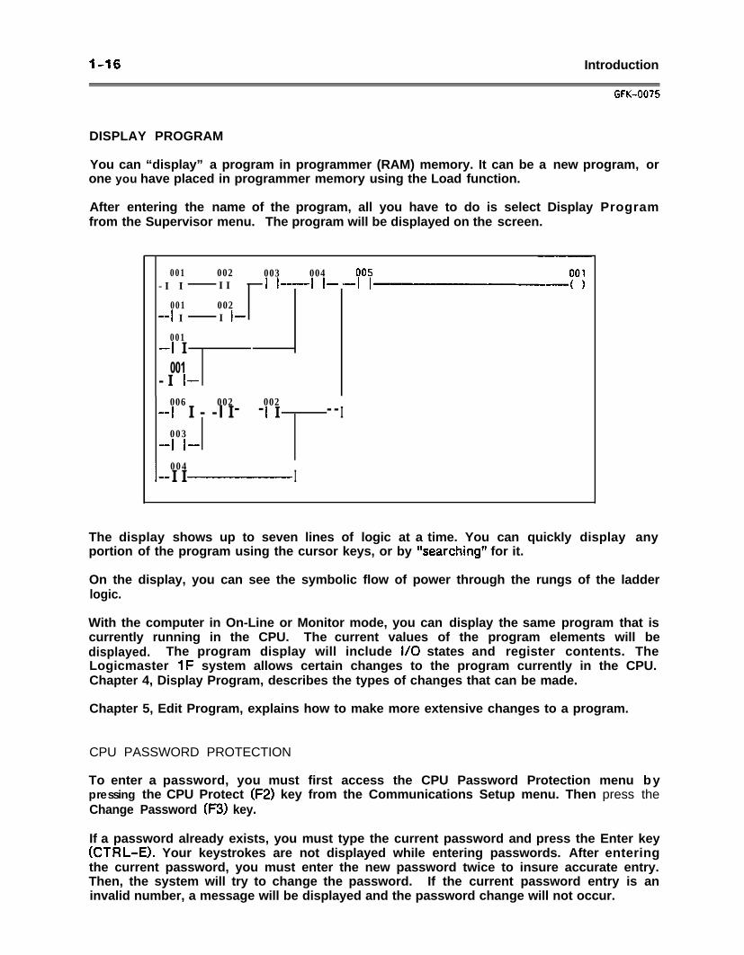
DISPLAY PROGRAM
You can “display” a program in programmer (RAM) memory. It can be a new program, orone you have placed in programmer memory using the Load function.
After entering the name of the program, all you have to do is select Display Programfrom the Supervisor menu. The program will be displayed on the screen.
001 002 003 004-I I II II-II-
001 002-I I I I-
001-I I
001- I l-
006 002 002-I I - - l I - - I I - - I
003-I I-
l-004I I-I-II-vI
00-I
The display shows up to seven lines of logic at a time. You can quickly display anyportion of the program using the cursor keys, or by %earching*’ for it.
On the display, you can see the symbolic flow of power through the rungs of the ladderlogic.
With the computer in On-Line or Monitor mode, you can display the same program that iscurrently running in the CPU. The current values of the program elements will bedisplayed. The program display will include I/O states and register contents. TheLogicmaster 1F system allows certain changes to the program currently in the CPU.Chapter 4, Display Program, describes the types of changes that can be made.
Chapter 5, Edit Program, explains how to make more extensive changes to a program.
CPU PASSWORD PROTECTION
To enter a password, you must first access the CPU Password Protection menu bypressing the CPU Protect (F2) key from the Communications Setup menu. Then press theChange Password (F3) key.
If a password already exists, you must type the current password and press the Enter key(CTRL-E). Your keystrokes are not displayed while entering passwords. After enteringthe current password, you must enter the new password twice to insure accurate entry.Then, the system will try to change the password. If the current password entry is aninvalid number, a message will be displayed and the password change will not occur.
Introduction l - 1 7
GFK-0075
If you press the wrong key while entering the password, you cannot use the Backspace orDelete keys to correct your error. You must continue with this attempt, which will beunsuccessful, and then try again.
Refer to section 3 in chapter 10 for more information on CPU password protection.
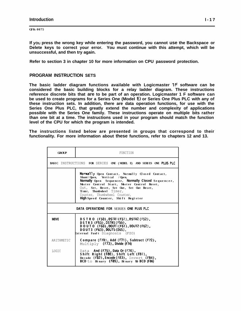
PROGRAM INSTRUCTION SETS
The basic ladder diagram functions available with Logicmaster 1F software can beconsidered the basic building blocks for a relay ladder diagram. These instructionsreference discrete bits that are to be part of an operation. Logicmaster 1 F software canbe used to create programs for a Series One (Model E) or Series One Plus PLC with any ofthese instruction sets. In addition, there are data operation functions, for use with theSeries One Plus PLC, that greatly extend the number and complexity of applicationspossible with the Series One family. These instructions operate on multiple bits ratherthan one bit at a time. The instructions used in your program should match the functionlevel of the CPU for which the program is intended.
The instructions listed below are presented in groups that correspond to theirfunctionality. For more information about these functions, refer to chapters 12 and 13.
GROUP FUNCTION
BASIC INSTRUCTIONS FOR SERIES ONE (MODEL E) AND SERIES ONE PtUS PLC
Normal'ly Open Contact, Normally Closed Contact,Shunt/Open, Vertical /Open,Normally Open Sequencer, Normally Closed Sequencer,Master Control Start, Master Control Reset,Out, Set, Reset, Set Out, Set Out Reset,Timer, Thumbwheel Timer,Counter, Thumbwheel Counter,High Speed Counter, Shift Register
DATA OPERATIONS FOR SERIES ONE PLUS PLC
MOVE D S T R O (F50), DSTRl (F51), DSTRZ (F52),D S T R 3 (F53), DSTRS (FSS),D O U T O (F60), DOUTl (F61), DOUTZ (F62),D O U T 3 (F63), DOUTS (D65),
External Fault Diagnosis (FZO)
ARITHMETIC C o m p a r e (F70), Add (F71), Subtract (F72),Multiply (F73), Divide (F74)
LOGIC Data And (F75), Data Or (F76),S h i f t R i g h t (F80), S h i f t L e f t (F81),Decode (F82), Encode (F83), Invert (F84),BCD to Binary (F85), Binary to BCD (F86)

Operation 2 - i
GFK-0075
CHAPTER 2OPERATION
This chapter explains what you will need to know to start up the Logicmaster 1 Familysoftware package, and to use the features described in this book.
There are 7 sections in this chapter. If you are already familiar with MS-DOS, you maywish to quickly peruse section 1 and go directly to section 2 to install the software, orsection 3 to start up the software.
Section 1. Using DOS: Section 1 describes DOS versions, and explains how to start upDOS, use DOS commands, format diskettes, and exit from Logicmaster 1F software toDOS.
Section 2. Installing Logicmaster 1 F Software: Before you use Logicmaster 1 F softwarefor the first time, follow the installation instructions in section 2.
Section 3. Starting Up Logicmaster 1 F Software: Refer to section 3 for instructions tostart up Logicmaster 1 F software using diskettes or a hard disk.
Section 4. Using Features of the Supervisor Menu: Section 4 describes the entries on theSupervisor menu. This section also explains how to specify a file name from theSupervisor Menu screen. .
Section 5. Using Your Keyboard: Section 5 explains the types of keyboards that may beused with Logicmaster 1 F software. This section also explains how to define special keyassignments to make programming easier.
Section 6. Entering Data: Section 6 explains the types of information you will see on thescreen. This section also explains how you will enter data, such as file names andnumerical values.
Section 7. Working with Numbers: Refer to section 7 for information about numbertypes: binary, decimal, BCD, hex, and octal.
2-2 Operation
GFK-0075
SECTION 1USING DOS
E?efore you can use Logicmaster 1F software, your computer must first be started up withDOS. DOS is not contained on the Logicmaster disks so it must be supplied separately.
This section provides a basic introduction to DOS.
Versions of DOSStarting up DOSEntering or changing the drive IDUsing DOS commandsFormatting diskettesFinding a fileExiting to DOS
The acronym DOS stands for Disk perating astern. DOS is a software program thatinterfaces other programs (like Logicmaster 1F) with the computer hardware. DOS mustbe used to start up Logicmaster IF software.
VERSIONS OF DOS
As with other types of software, there are different versions of DOS. To run Logicmaster1 F software, you must use a compatible version of DOS.
0 For a Workmaster or Cimstar I industrial computer, you should use MS-DOS@ version3.2. If you have a copy of the earlier GE version 3.14 of MS-DOS, it can be used fora Workmaster computer with diskette drives or a 10 mbyte hard disk.L
0 For a Workmaster II industrial computer, you must use MS-DOS version 3.3.
0 For an IBM PC or PC-XT computer, you must use PC-DOS version 2.10, or later. AnIBM PC-AT requires PC-DOS version 3.0, or later. (The term PC-DOS refers to thesoftware supplied by IBM as ‘DOS Disk Operating System for IBM personalcomputers”.)
0 For an IBM PSI2 computer, you must use PC-DOS version 3.3 or 4.0.
Determining the DOS Version Number
If you are not sure what version DOS you have, start up the computer in DOS, asdescribed on the following page. The copyright screen will display the DOS versionnumber.
If you are already in DOS, you can display the DOS version by entering the followingcommand:
A> VER
and pressing the Return key.
Operation
GFK-0075
2-3
STARTING UP DOS
DOS can be run from the diskette or from a hard disk. To start up DOS, follow theseinstructions:
1 .
2 .
3 .
4 .
The DOS software must be in the computer. If DOS is not installed on a hard disk,place your DOS diskette in drive A.
Start up the computer. If the computer was already running, you can restart bypressing CTRL-ALT-DEL, or a Reset button. Otherwise, turn on power to thecomputer.
The copyright screen is displayed while the DOS software is loaded into programmermemory. When the date and time prompts are displayed, you can enter the requestedinformation, or press the Return key to continue.
The DOS command prompt appears.
A>
This prompt shows the letter ID of the drive. If you used a diskette in drive A tostart up DOS, then the prompt will indicate drive A. This is the “current” drive.
The cursor appears at the prompt. If you wanted to use one of the DOS commands,you would type it here, and press the Return key. If you wanted to run a softwareprogram from a diskette or hard disk, you would enter its command line.
ENTERING OR CHANGING THE DRIVE ID
DOS assigns an identifying letter to each drive in the computer. The letter assignmentsdepend on the type of computer you are using, and how its hardware is set up.
When you start up or reset the computer, it will check drive A for a diskette with certainsystem files. If these files are present, the contents of the diskette in drive A will beloaded into the programmer memory of the computer. This is what happens when youload DOS from a diskette. After the software is loaded, the drive A command prompt isdisplayed. Drive A is now the current drive.
If the computer does not find the system files in drive A, it will look for a hard disk. (If anon-system disk is in drive A, an error message is displayed.) If the system files are on ahard disk, it will load those files into programmer memory and the hard disk drive promptwill be displayed. In this case, the hard disk becomes the current drive.
Changing the Current Drive
To change the current drive, enter the new drive ID followed by a colon and press theReturn key. The following example changes the current drive from C to A.
0C>A:A>
(and press the Return key.)
Now, the computer will go to drive A to execute commands, rather than to drive C.
2-4 Operation
USING DOS COMMANDS
Your DOS manual explains how to use DOS, and provides complete definitions of all DOScommands. Each time you enter a command, DOS will perform some function for you.You will use the following commands to install and start up Logicmaster 1F software:
COPY To copy one or more files, either on the same disk or from one disk toanother, use the Copy command. For example, to copy a f i le namedCONFIG.WM to the same disk, and call the copy CONFIG.SYS, you wouldenter:
COPY CONFIGJJM CONFIGSYS
To rename a file, use the Rename command. For example, to rename a filenamed CONFIG.WM as CONFIGSYS (on the same drive) you would enter:
REN CONFIG.WM CONFIGSYS
TYPE Use the Type command when you want to display a file on the computerscreen. For example:
TYPE CONFIG.SYS
Any kind of file can be displayed with the Type command. If the file is notan ASCII (readable) file, it will appear as an assortment of characters andbeeps. One kind of file displayed in that way is a ladder logic file. Youcannot use DOS to display a ladder logic file in recognizable form. To seethe ladder logic, you must enter Logicmaster lF, load the file intoprogrammer memory, and then use Edit Program or Display Program.
FORMATTING DISKETTES
Before you can use a new diskette, it must be initialized. The Format command preparesa diskette to receive data. You should remember that formatting erases any datapreviously placed on the diskette. Don’t format a diskette that contains data you want tosave. To format a diskette, follow these steps:
1 . Start up the computer in DOS. At the DOS prompt, type:
FORMAT (drive:)
2 . Insert a write-en&dd diskette into the specified drive. Press the Return key.Follow the prompts lt8t format the diskette.
Operation 2-5~.
GFK-0075
FINDING A FILE
DOS will display a listing of all of the files on a drive. This listing is called a‘*directory”. The directory shows the name of each file, its extension, its size, and thedate and time it was last edited.
If you want to display a directory, enter the Directory command. For example:
A> DIR displays the directory of the disk in drive A, when drive A isthe current drive.
A> DIR B: displays the directory of the disk in drive B, when drive A isthe current drive.
B> DIR displays the directory of the disk in drive B, when drive B isthe current drive.
The Directory command causes the file listing to scroll rapidly upward on the screen. Ifthe listing is too long to fit on one screen, you can display just one screen at a time byentering the characters /P after the command. For example:
A> DIR 6:/P
This command would cause DOS to display a directory of the files on the disk in drive B.After the first screen of the listing is displayed, pressing any key displays the next screen.
Wildcard characters can be used to display a directory of related files on a disk. Forexample:
A> DIR 8: *.LAD
This command would display a directory of all .LAD files on the disk in drive B.
2-6 Operation
UK-0075
EXITING TO DOS FROM LOGICMASTER 1F SOFTWARE
When Logicmaster 1F software is running in the computer, you can ex ifr~i-~i the Supervisor menu. You may want to do this, for example, if yo Ldiskette using DOS. Be careful exiting to DOS if there is a ladderprogrammer memory that you want td keep. Exiting to DOS is justcomputer; the contents of programmer memory will be lost.
t directly to DOSJ need to format alogic program inike restarting the
If you have been editing a program that has an active file name, it has automatically beensaved to disk each time you press CTRL-A or the Accept key. If the program does nothave an active file name, before exiting to DOS you should store the program using theLoad/Store/Verify function of Logicmaster 1 F. If necessary, you can use any formatteddiskette to store the program.
To exit to DOS from the Supervisor menu, follow these steps:
1 . Press the ALT and Z keys. If your computer has a hard disk, it. will return to DOS. Ifyou are using DOS diskettes to start up the computer, your screen may display thefollowing prompt:
Insert disk with \COMMAND.COM in drive Aand strike any key when ready
Place a diskette with a COMMAND.COM file in drive A. This should be your DOSdiskette. Press any key to continue. If you do not have a diskette with aCOMMANDXOM file, you will not be able to continue this procedure. You shouldrefer to your DOS manual for more information about the COMMAND.COM file.
If you are running Logicmaster 1F software from diskettes, the screen may nowprompt:
Insert disk with batch fileand press any key when ready
If that prompt is displayed, place a diskette with a batch file in drive A. Diskette 1of the Logicmaster 1 F diskettes contair
2 . The DOS command prompt will be displbe the drive A prompt:
A>
7s a batch file. Press any key to continue.
ayed. If you have been using diskettes, it will
3 . To return to the Logicmaster 1F software,line. (Refer b page 2-8 for an explanation of
If you are using diskettes, the Logicmasterdrive. Press the Return key.
enter LlFWM or LlFPC on the commandwhich command to enter.)
1F diskette 1 must be in the default
Operation 2-7
GFK-0075
SECTION 2INSTALLING LOGICMASTER 1 F SOFTWARE
Ordinarily, you will use the information in this section once, to prepare Logicmaster 1 Fsoftware for regular use. This section describes:
1 F software.The diskettes supplied with Logicmaster ’
The types of System Configuration f ilsoftware.
es that are supplied with Logicmaster 1F
The correct content of the CONFIG.SYS file for the type of computer you are using.
Editing the System Configuration file, if necessary.
lnstal ling Logicmaster 1 F software on a hard disk.
For the Workmaster or Cimstar I computer, 3%.inch diskette only: customizingLogicmaster 1F system diskettes so that they can be started up without DOS.
BEFORE USING LOGICMASTER 1 F SOFTWARE
Before you use Logicmaster 1F software regularly, you should follow the instructions inthis section.
1 . Check the content of your System Configuration CONFIGSYS file. This file mustagree with your hardware setup. If necessary, edit or create this file on yourstart-up disk.
2 . If your computer has a hard disk, install Logicmaster 1F software on the hard disk.
3 . If you are using either a Workmaster or Cimstar I computer with 3%.inch diskettes,you can create a start-up diskette. This will eliminate the need for using a DOSdiskette to start up the Logicmaster 1F software.
2-a Operation
GFK-0075
LOGICMASTER 1 F SYSTEM DISKETTES
Logicmaster 1 F software is supplied on diskettes as described below:
1 . For computers with 3%.inch drives with 80 track format, such as that provided withthe Workmaster or Cimstar I computer, the software is provided on one 3%~inchdiskette. Starting up the software will take you to the Supervisor menu, with allsoftware functions loaded into programmer memory.
2 . For IBM PC-XT, PC-AT, and most IBM-compatible computers with S!&inch diskdrives with 40 track format, such as that provided with the IBM personal computer,the software is provided on two 5YZnch diskettes. Starting up the software withdisk 1 in the drive will proceed to the Clock Setup menu. Then you will be promptedto insert the second disk. When the second disk finishes loading, the Supervisor menuwill be displayed, with all software functions loaded into programmer memory.
Once installed and/or set up properly, either configuration of the Logicmaster 1 Family(LlF) programmer (described above) will operate in one of two ways:
1 . Enter LIFWM to start the software for operation on the Workmaster or Cimstar Icomputer. The Logicmaster 1F software wi,ll recognize the Workmaster keyswitch.
2 . Enter LlFPC to start the software for operation on the Wotkmaster II computer, anIBM-PC, PC-XT, or PC-AT computer, and most IBM compatible computers. Referto section 6 of this chapter for alternate key sequences required fornon-Workmaster, IBM-compatible keyboards.
CHANGING THE ORIGINAL LOGICMASTER 1F FILES
All files provided with Logicmaster 1 F software are read-only files. They can berenamed, but they cannot be copied over, deleted, or edited. Unused files can be left onthe disk; they will not interfere with operation of the Logicmaster 1F software. If youwant to edit one of these original files (including any of the System Configuration files),you must copy and rename the file first; then edit the copy.
BEFORE STARTING UP LOGICMASTER IF SOFTWARE THE FIRST TIME
Use the original diskettes to start up the system the first time. Then, use the DuplicateMaster utility of Logicmaster 1F software to make copies of the diskettes. Use thecopies for everyday diskette operations; keep the originals in a protected location.Complete instructions for using Duplicate Master are given in chapter 11.
Before using the Dugtic~~e Masfer utility, prepare the diskettes for the working copy byusing the DOS Format command.
Operation
GFK-0075
2-9
SYSTEM CONFIGURATION FILE
To run Logicmaster 1 F software, the disk you use to start up the computer must contain aSystem Configuration file with the name CONFIG.SYS. When a hard disk is used as thestart-up disk, the CONFiG.SYS file must be in the root directory of the hard disk. Therequired content of the file is discussed below.
The CONFIG.SYS file is a short, readable file that describes the system requirements forthe software package. Different software packages use different system configurationfiles, depending on the software requirements and the existing hardware conf igbration.Your DOS diskette should already contain a CONFIGSYS file. The computer uses thisfile at boot-up time to establish the system configuration. If the content of theCONFIG.SYS file is changed after boot-up, the computer must be re-booted before thechanges will take effect.
Sample system configuration files are provided with Logicmaster 1 F software forreference. One of these two files will probably meet most application requirementswithout change. The content of these files is discussed below:
1 . The CONFIG.PC file (for Workmaster II computers, Cimstar I computers, IBMpersonal computers, and most IBM-compatible computers) contains three lines whichmust be in the CONFIG.SYS for all computers running Logicmaster IF software.These lines are:
buffers = 5files = 20device = ansi,sys
The entry for buffers must be 5, and the entry for files must be 20. The devicedriver calls for a file named ANSI.SYS. The ANSI.SYS file must be present on theDOS disk for Logicmaster 1F software to run. .
2. The CONFIG.WM file (for Workmaster computers) contains the same three lines, asprovided in the CONFIG.PC file. It also contains one additional line specificallyrequired for the Workmaster computer. This additional line enables the device driverfor the Workmaster clock. The CONFIG.WM file contains:
buffers = 5files = 20device = ansi.sysdevice = wmclock.sys
If the CONFlG.SYS file on your DOS disk does not contain the above information, youmust create a file that does. You can copy one of the above files or modify your existingfile. It is wise to save your existing CONFIG.SYS file in case you need to refer back toit. Then, you can copy one of the above files to make the CONFIG.SYS file.
If changes ate still required to the CONFIG.SYS file, you will need to know how to use atext editor. A brief discussion of EDLIN (Line Editor supplied with DOS) can be found onthe following page (see “WORKING WITH THE CONFIG.SYS FILE”).
2-l 0 Operation
GFK-0075
For a Workmaster Computer with a S!&Inch Disk Drive
if you are using MS-DOS version 3.2 and your Workmaster or Cimstar I computer has aS&inch disk drive, you should place a DRIVPARM command in the CONFIG.SYS file.This line tells DOS the capacity of diskettes placed in the drive, which is important whenformatting disks.
For example, if you have a Workmaster computer with two 3!&inch drives (A and B) andan external 9Linch floppy drive (C), the following line will specify that drive C has thestandard 40,track, 360K byte form factor:
DRIVPARM-lD:2 /F:O
In this example, the 2 refers to drive(360K). If you do not use this line,correct for 3!&inch drives. ReferDRIVPARM command.
C (O=A, l=B, and Z=C), and 0 refers to form factor 0DOS assumes form factor 2 (760K), which is onlyto your DOS manual for more information on the
Running Other Software with the CONFIG.SYS File for Logicmaster 1 F
Other types of software may require different entries in the CONFIG.SYS file. It is notalways possible to combine the requirements for multiple software packages into oneCONFIG.SYS file. In that case, you must maintain multiple versions of the CONFIG.SYSfile. That can be done by using multiple DOS diskettes, or by renaming versions of theCONFIGSYS file and usingre-boot your system if theinformation about the CONF
the one required for a specific application. Remember TVCONFIGSYS is changed. Your DOS manual contains moreG.SYS file.
WORKING WITH THE CONF G.SYS FILE
Follow the instructions below if you need to display, create, or edit a CONFIG.SYS file.
Displaying the CONFIG.SYS File
Use the DOS Directory command, as explained previously, to display the contents of yourDOS disk. If there is a CONFIGSYS file on the disk, you can display its contents byentering:
TYPE CONFIGSYS (press Return)
Creating a CONFIG.SYS File
If you do not have a CONFIG.SYS file, create one as described below. Note that thisprocedure will write over any existing version of the CONFlG.SYS file. If such a versionexists, rename it CONFIG.BAK before following these steps.
1 . At the DOS prompt, type:
COPY CON CONFIGSYS
2 . Press CTRL-E or the Enter key.
Operation 2-l 1
GFK-0075
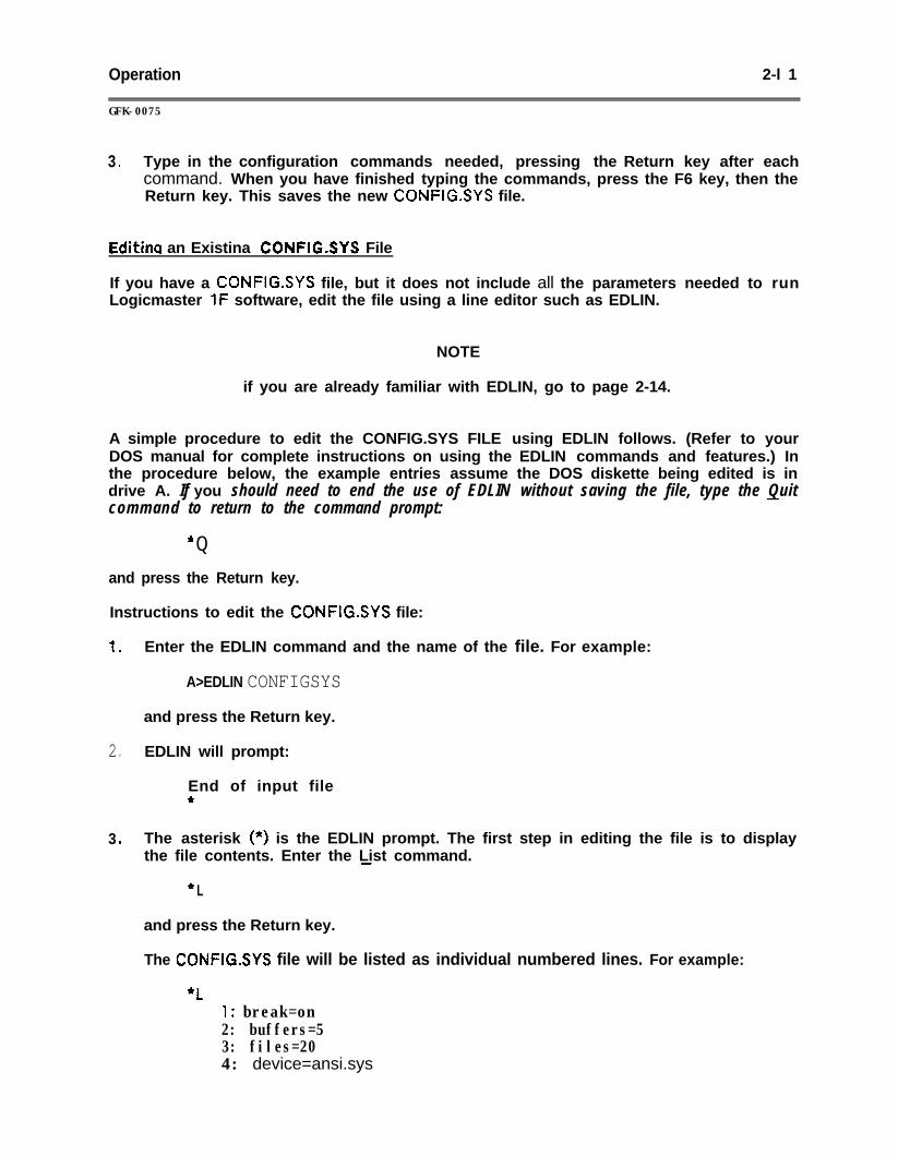
3 . Type in the configuration commands needed, pressing the Return key after eachcommand. When you have finished typing the commands, press the F6 key, then theReturn key. This saves the new CONFIG.SYS file.
Edith an Existina CONFIG.SYS File
If you have a CONFIG.SYS file, but it does not include all the parameters needed to runLogicmaster 1F software, edit the file using a line editor such as EDLIN.
NOTE
if you are already familiar with EDLIN, go to page 2-14.
A simple procedure to edit the CONFIG.SYS FILE using EDLIN follows. (Refer to yourDOS manual for complete instructions on using the EDLIN commands and features.) Inthe procedure below, the example entries assume the DOS diskette being edited is indrive A. If you should need to end the use of EDLIN without saving the file, type the Quitcommand to return to the command prompt:
* Q
and press the Return key.
Instructions to edit the CONFIGSYS file:
1 . Enter the EDLIN command and the name of the file. For example:
A>EDLIN CONFIGSYS
and press the Return key.
2 . EDLIN will prompt:
End of input file*
3 . The asterisk (*) is the EDLIN prompt. The first step in editing the file is to displaythe file contents. Enter the List command.-
* L
and press the Return key.
The CONFlG.SYS file will be listed as individual numbered lines. For example:
*L1: break=on2: buffers=53: files=204: device=ansi.sys
2-l 2 Operation~~GFK-0075
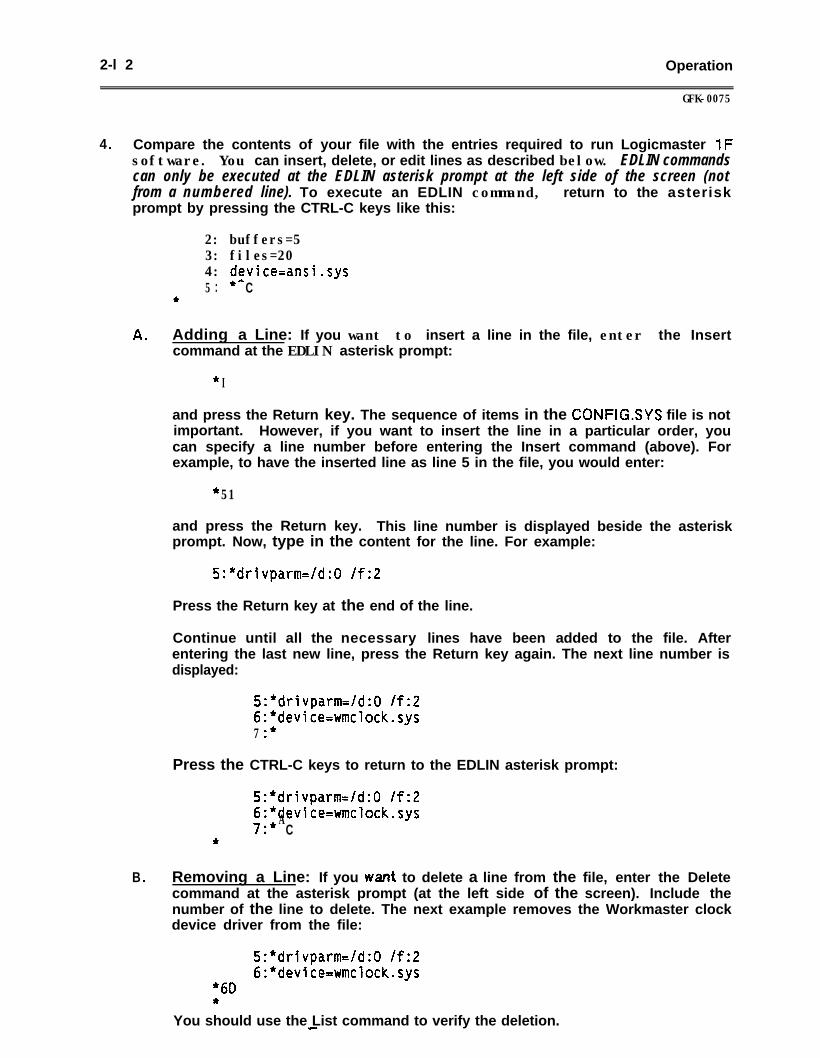
4 . Compare the contents of your file with the entries required to run Logicmaster 1Fsoftware. You can insert, delete, or edit lines as described below. EDLIN commandscan only be executed at the EDLIN asterisk prompt at the left side of the screen (notfrom a numbered line). To execute an EDLIN command, return to the asteriskprompt by pressing the CTRL-C keys like this:
2: buffers=53: files=204: device=ansi.sys5 . **. C
*
A . Adding a Line: If you want to insert a line in the file, enter the Insertcommand at the EDLIN asterisk prompt:
* I
and press the Return key. The sequence of items in the CONFGSYS file is notimportant. However, if you want to insert the line in a particular order, youcan specify a line number before entering the Insert command (above). Forexample, to have the inserted line as line 5 in the file, you would enter:
* 51
and press the Return key. This line number is displayed beside the asteriskprompt. Now, type in the content for the line. For example:
%*drivparm=/d:O /f:Z
Press the Return key at the end of the line.
Continue until all the necessary lines have been added to the file. Afterentering the last new line, press the Return key again. The next line number isdisplayed:
S:*drivparm=/d:O /f:26:*device=wmclock.sys7 .*.
Press the CTRL-C keys to return to the EDLIN asterisk prompt:
5:*drivparm=/d:O /f:26:*device=wmclock.sys7*
A.. C*
B . Removing a Line: If you w& to delete a line from the file, enter the Deletecommand at the asterisk prompt (at the left side of the screen). Include thenumber of the line to delete. The next example removes the Workmaster clockdevice driver from the file:
5:*drivparm=/d:O /f:26:*device=wmclock.sys
* 60*
You should use the List command to verify the deletion.
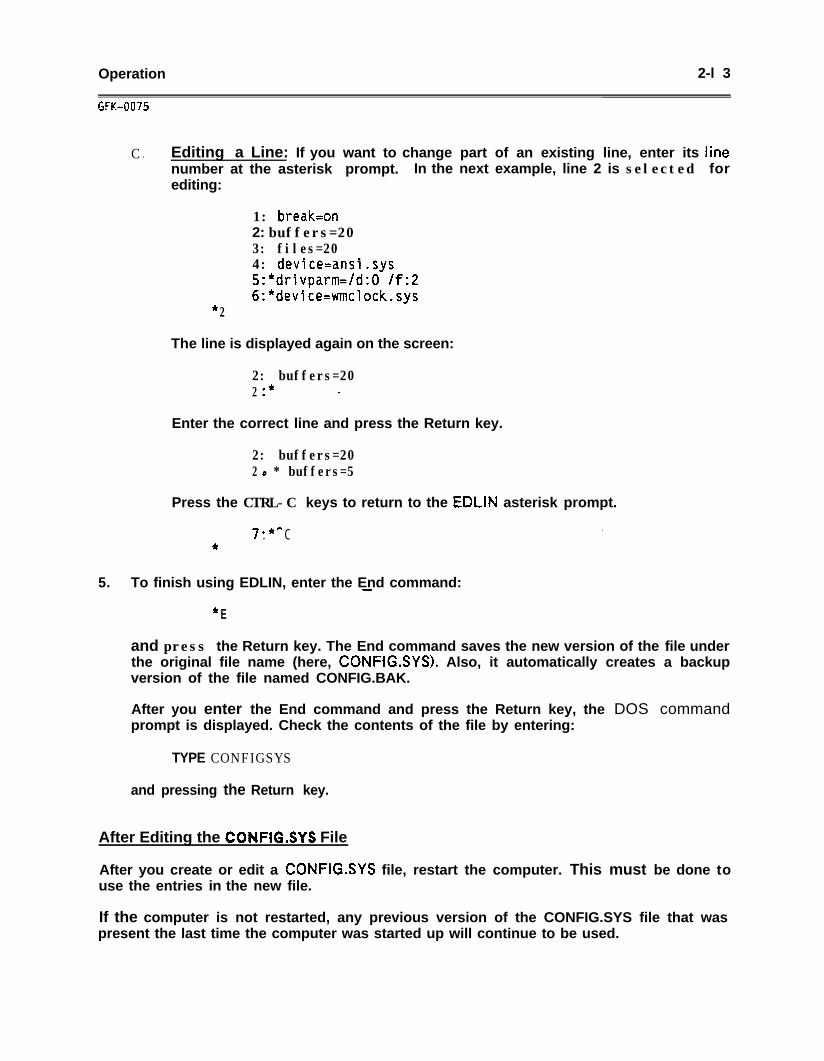
Operation 2-l 3
GfK-0075
C . Editing a Line: If you want to change part of an existing line, enter its linenumber at the asterisk prompt. In the next example, line 2 is selected forediting:
1: breakton2: buffers=203: files=204: device=ansi.sys5:*drivparm=/d:O If:26:*device=wmclocksys
* 2
The line is displayed again on the screen:
2: buffers=202 .* ..
Enter the correct line and press the Return key.
2: buffers=202 l * buffers=5.
Press the CTRL-C keys to return to the EDLIN asterisk prompt.
7 **. C ..*
5. To finish using EDLIN, enter the End command:-
+ E
and press the Return key. The End command saves the new version of the file underthe original file name (here, CONFIG.SYS). Also, it automatically creates a backupversion of the file named CONFIG.BAK.
After you enter the End command and press the Return key, the DOS commandprompt is displayed. Check the contents of the file by entering:
TYPE CONFIGSYS
and pressing the Return key.
After Editing the CONFlG.SYS File
After you create or edit a CONFIGSYS file, restart the computer. This must be done touse the entries in the new file.
If the computer is not restarted, any previous version of the CONFIG.SYS file that waspresent the last time the computer was started up will continue to be used.
2-l 4 Operation
iNSTALLATl0N: COMPUTER WITHOUT A HARD DISK
With the correct CONFIG.SYS file on the DOS disk, boot up the computer in DOS. Insertthe Logicmaster 1F system disk #l in drive A: and start it up by entering either LlFWMfor Workmaster and Cimstar I computers or LlFPC for Workmaster II computers, IBMpersonal computers, and most IBM-compatible computers.
Preparing Bootable Loqicmaster I F System Diskettes
Copies of the 3%~inch version of Logicmaster IF can be made %ootable” by preparing asystem disk containing DOS system files, and then transferring a copy of Logicmaster 1Fto the disk. The master diskette shipped from GE Fanuc cannot be made bootable. T oprepare a Logicmaster 1 F bootable 3!&inch system diskette, it is best to use a computerwith two disk drives.
1 . First, start up the computer with the DOS disk in drive A.
2 . Insert a new disk into drive B so the disk can be formatted as a system disk. All dataon the disk will be erased as it is formatted. A copy of DOS system files will betransferred to the new disk by entering the following command:
FORMAT B: /S
3. Enter the following commands to copy additional system files from the DOS disk tothe newly formatted disk:
COPY A:ANSI.SYS B:
If the disk is being made to run on the Workmaster computer, you must also copy thefollowing file from the DOS diskette. (This does not apply to the Workmaster IIcomputer .I
COPY A:WMCLOCK.SYS 8:
4 . Insert the Logicmaster 1F master disk in drive A and copy the proper systemconfiguration file to the newly formatted disk as follows:
A .
B .
If the disk is being made to run on the Workmaster computer, copy thefollowing file from the Logicmaster 1 F diskette:
COPY A:CONFIG.WM B:CONFIG.SYS
If the disk is being made to run on the Workmaster II, Cimstar I, IBM-PCcomputer, or IBM-compatible computer, copy the following file from theLogicmaster 1 F diskette:
COPY A:CONFIG.PC B:CONFIG.SYS
Operation 2-l 5
GFK-0075
5. Start up the Logicmaster 1 F software and go to the Duplicate Master utility.Proceed to duplicate the master disk (in drive A) to the newly formatted disk (indrive B). Refer to chapter 11 for more information on Duplicate Master.
This completes the making of a bootable disk. You may insert the new disk into drive Aand restart the computer. After DOS starts up, you will be prompted to enter eitherLlFWM or LlFPC to start up the Logicmaster 1F software.
The AUTOEXEC.BAT file can be modified to automatically start upthe Logicmaster 1F software after DOS boots up. Simply add theLlFWM command as the last line in the AUTOEXEC.BAT file.
INSTALLATION: COMPUTER WITH A HARD DISK
These instructions describe steps to install Logicmaster 1F files on a computer with ahard disk. (If you prefer to run the software using diskettes, refer to the instructions fora computer without a hard disk.)
1 . The hard disk should already be formatted, and DOS should be installed. For moreinformation about DOS, refer to your DOS manual. The following files should be inthe root directory of your hard disk: l
ANSI .SYS provided with your DOS.CONFlG.SYS system conf igufat ion requirements for Logicmaster IF
software.WMCLOCK.SYS only required for the Workmaster computer. (This does not
apply to the Workmaster II computer.)
The System Configuration file used by your computer at start-upshould contain the appropriate information prior to starting upLogicmaster 1 F software. Refer to page Z-10 for additionalinformation regarding the CONFIG.SYS file. If the CONFIG.SYSfile used by DOS during start-up is revised, you must restart thecomputer before the new file becomes active.
2. Start up the computer in DOS. When the DOS command prompt is displayed, placethe Logicmaster IF disk 1 in drive A and enter one of the following commands tostart up Logicmaster 1 F software:
LlFwMLl FPC
(if using a Workmaster or Cimstar I computer)(if using a Workmaster II, IBM-PC, or IBM-compatiblecomputer)
Press the Return key. The Logicmaster system will prompt you to enter the timeand date. (If using 5!&inch disks, you will be prompted to insert system disk 2.)
2-l 6 Operation
GFK-0075
3 . Follow these steps to duplicate the software:
A . Select Utility functions by pressing F8 at the Supervisor level.
B . Select Duplicate Master function by pressing Fl in the Utility function.
C . Enter A as the drive to duplicate from and your hard disk as the drive toduplicate to.
D . Press CTRL-E or the Enter key to begin the duplication of the software.
if using %-inch disks, repeat the duplication process so both disks will be duplicatedto the hard disk.
4 . Once the duplication process is complete, you may return to the Supervisor menu,and then exit to DOS by pressing the ALT-Z keys. The master disks should beremoved and placed in a protected location.
5 . A new LlF directory was created on the hard disk containing a copy of theLogicmaster 1 F system files. Change to the Ll F directory, and start up the softwarefrom the hard disk using either the LlFWM or LlFPC command.
Specifying the Path for a Hard Disk
Since the Duplicate Master automatically creates a subdirectory called LlF on the harddisk, you may wish to add this directory to a path statement. This will supply DOS with apath to \Ll F subdirectory from other directories or disk drives. This is normally done byplacing a path statement in the AUTOEXEC.BAT start-up file. For example:
PATH \LlF
This statement will define the path each time the system is booted. If you already have apath statement, you can add the \LlF path to the end of that statement. For example:
PATH D:\;D:\DOS;D :\LlF
will tell DOS to first look forDOS subdirectory on drive Dcourse, DOS always looks inpath.
the command in the root directory of drive D, then look in aand finally look in the Ll F subdirectory on drive D. Of
the current directory of the current drive before using the
Operation 2-l 7
GFK-0075
SECTION 3STARTING UP LOGICMASTER 1 F SOFTWARE
After the installation procedures described in the preceding section have been completed,you can start up Logicmaster 1 F software normally.
This section describes the following procedures for regular start-up of Logicmaster 1Fsoftware.
0 Entering the Logicmaster 1F command line.
l Displaying the Logicmaster 1 F title screen.
a Changing the time and date.
0 Displaying the Supervisor menu.
USING OTHER TYPES OF SOFTWARE: RAM REQUIREMENTS
Logicmaster 1 F software requires that 640K of programmer memory (RAM) be availablein your computer. The Logicmaster 1F software will fail to start up if you attempt to runit simultaneously with other software packages (i.e., VTERM of Sidekick).
Communications Setur, File .
At start-up the system looks for a file named COMSETSET. This file describes the serialcommunications configuration of the system. Ifor On-Line mode (implying communications withestablish communications with the CPU, andCOMSET.SET file is present and specifies a validscreen displays the message:
the system is started up in Monitor modethe CPU), the serial version attempts toread in the scratch pad settings if theport. If an invalid port is specified, the
INVALID PORT SPECIFIED IN COMSETSET
If communications cannot be established, the system supplies default settings for theitems in the scratch pad.
2-l $ Operation
GFK-0075
ENTERING THE LOGICMASTER 1F COMMAND LINE
Follow these steps to start up the Logicmaster 1F software.
NOTE
If you are using a computer with a hard disk, the Logicmaster 1Fsoftware should be installed on the hard disk as described in thepreceding sect ion. With the software installed on the hard disk,begin at step 3 below.
1 .
2 .
3 .
4 .
Start up the system using the appropriate DOS (as expI.ained in the precedingsection). If the computer is turned off, apply power. If the computer is alreadyturned on when you insert the diskette, you can perform a software start by pressingthe CTRL-ALT-DEL keys at the same time. After the DOS software is loaded, theDOS command prompt is displayed:
A>
Insert Logicmaster 1F diskette 1 in drive A.
At the DOS command (drive) prompt, type one of the following:
Ll FWM
Of
to start Logicmaster 1F software on either theWorkmaster or Cimstar 1 computer.
Ll FPC to start Logicmaster 1F software on a Workmaster II,IBM personal computer, or IBM-compatible computer.
After entering the Logicmaster 1F command, press the Return key. Follow theprompts that are displayed to display the Supervisor menu.
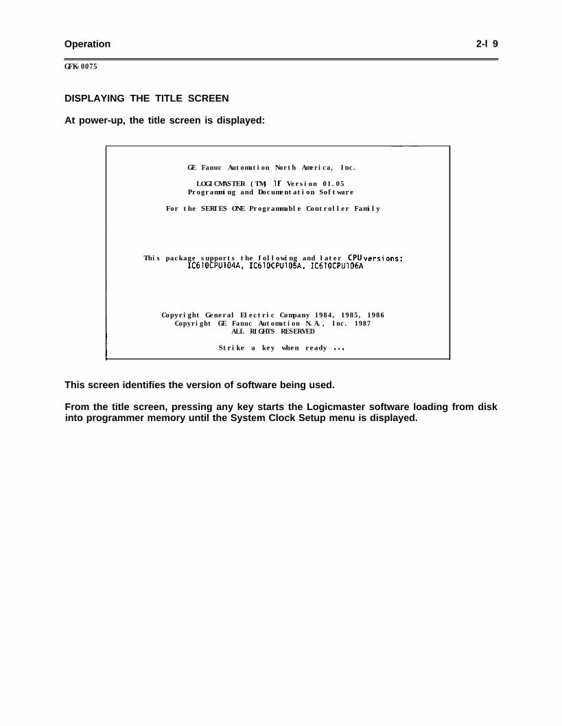
Operation 2-l 9
GFK-0075
DISPLAYING THE TITLE SCREEN
At power-up, the title screen is displayed:
GE Fanuc Automation North America, Inc.
LOGICMASTER (TM) 1F Version 01.05Programming and Documentation Software
For the SERIES ONE Programmable Controller Family
This package supports the following and later CPU versions:IC61OCPU104A, IC610CPU105A, IC61OCPUl06A
Copyright General Electric Company 1984, 1985, 1986Copyright GE Fanuc Automation N.A., Inc. 1987
ALL RIGHTS RESERVED
Strike a key when ready . . .
This screen identifies the version of software being used.
From the title screen, pressing any key starts the Logicmaster software loading from diskinto programmer memory until the System Clock Setup menu is displayed.
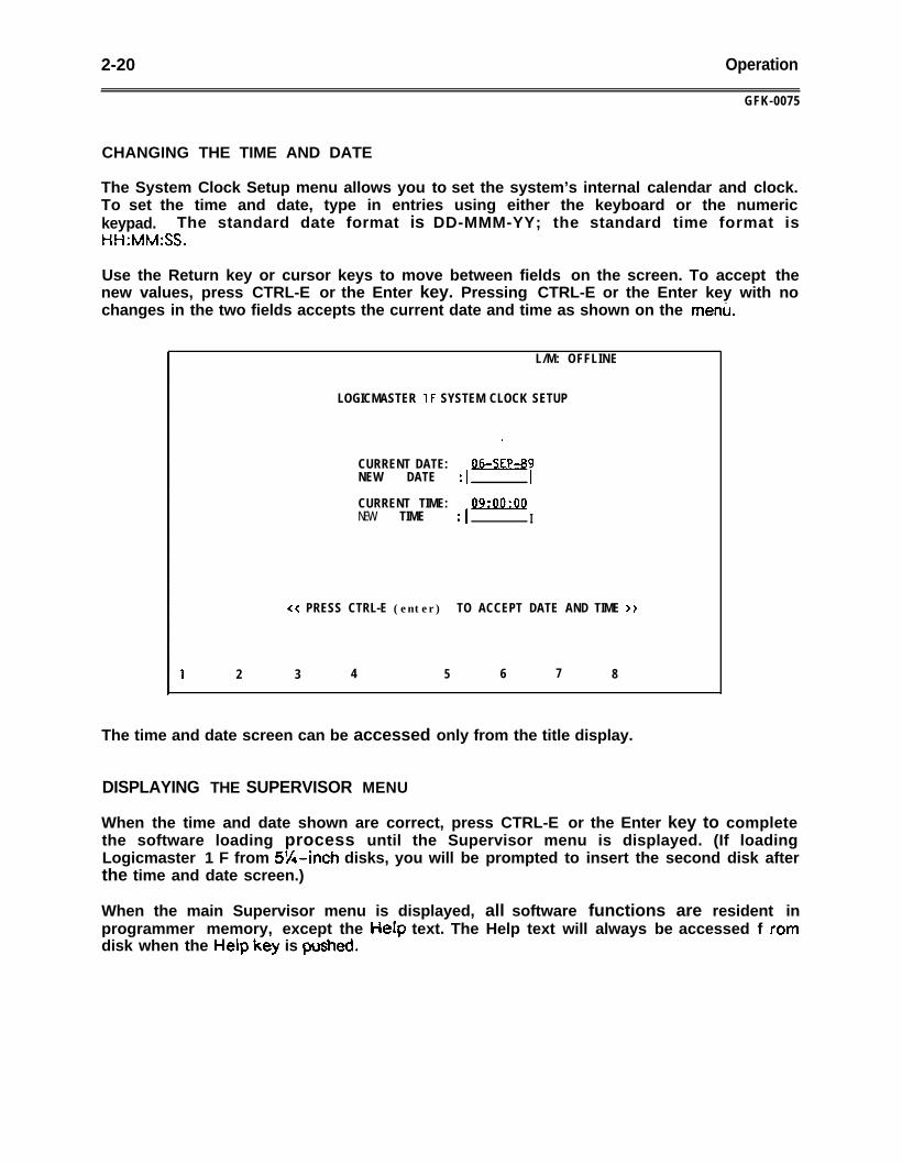
2-20 Operation
GFK-0075
CHANGING THE TIME AND DATE
The System Clock Setup menu allows you to set the system’s internal calendar and clock.To set the time and date, type in entries using either the keyboard or the numerickeypad. The standard date format is DD-MMM-YY; the standard time format isHH:MM:SS.
Use the Return key or cursor keys to move between fields on the screen. To accept thenew values, press CTRL-E or the Enter key. Pressing CTRL-E or the Enter key with nochanges in the two fields accepts the current date and time as shown on the menu.
L/M: OFFLINE
LOGICMASTER 1F SYSTEM CLOCK SETUP
CURRENT DATE:NEW DATE : 1
CURRENT TIME:NEW TIME : 1
09:OO:OQI
<< PRESS CTRL-E (enter) TO ACCEPT DATE AND TIME >>
1 2 3 4 5 6 7 8
The time and date screen can be accessed only from the title display.
DISPLAYING THE SUPERVISOR MENU
When the time and date shown are correct, press CTRL-E or the Enter key to completethe software loading process until the Supervisor menu is displayed. (If loadingLogicmaster 1 F from 5%inch disks, you will be prompted to insert the second disk afterthe time and date screen.)
When the main Supervisor menu is displayed, all software functions are resident inprogrammer memory, except the He@ text. The Help text will always be accessed f ramdisk when the Heip key is PuspIed.
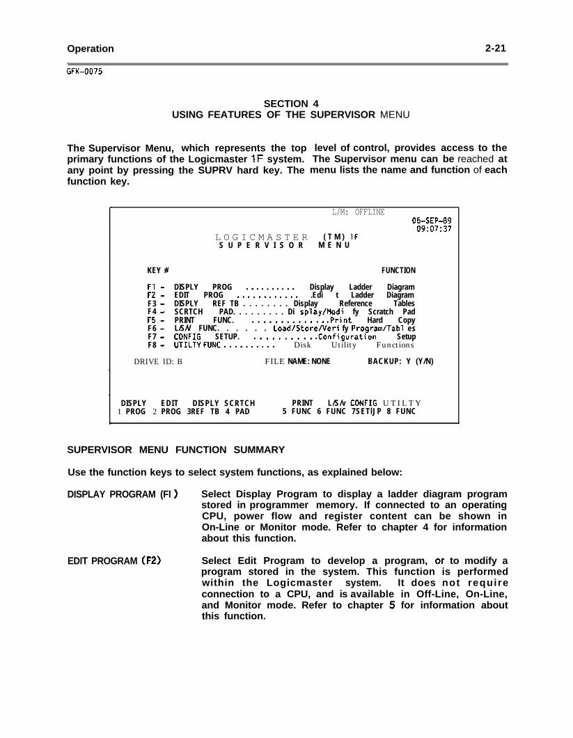
Operation 2-21
GFK-0075
SECTION 4USING FEATURES OF THE SUPERVISOR MENU
The Supervisor Menu, which represents the topprimary functions of the Logicmaster 1F system.any point by pressing the SUPRV hard key. Thefunction key.
level of control, provides access to theThe Supervisor menu can be reached atmenu lists the name and function of each
L/M: OFFLINE06-SEP-8909:07:37
L O G I C M A S T E R ( T M ) 1FS U P E R V I S O R M E N U
KEY # FUNCTION
Fl - DISPLY PROG . . . . . . . . . . Display Ladder DiagramF2 - EDIT PROG . . . . . . . . . . . . .Edi t Ladder DiagramF3 - DISPLY REF TB . . . . . . . . Display Reference TablesF4 - SCRTCH PAD. . . . . . . . . Di splay/Modi fy Scratch PadF5 - PRINT FUNC. . . . . . . . . . . . . . .Print Hard CopyF6 - L/S/V FUNC. . . . . . Load/Store/Veri fy Program/Tab1 esF7 - CONFIG SETUP. . . . . . . . . . . .Configuration SetupF8 - UTILTY FUNC . . . . . . . . . . Disk Utility Functions
DRIVE ID: B FILE NAME: NONE BACKUP: Y (Y/N)
DISPLY EDIT DISPLY SCRTCH PRINT L/S/v CONFIG UTILTY1 PROG 2 PROG 3REF TB 4 PAD 5 FUNC 6 FUNC 7SETlJP 8 FUNC
SUPERVISOR MENU FUNCTION SUMMARY
Use the function keys to select system functions, as explained below:
DISPLAY PROGRAM (Fl ) Select Display Program to display a ladder diagram programstored in programmer memory. If connected to an operatingCPU, power flow and register content can be shown inOn-Line or Monitor mode. Refer to chapter 4 for informationabout this function.
EDIT PROGRAM (F2) Select Edit Program to develop a program, or to modify aprogram stored in the system. This function is performedwithin the Logicmaster system. It does not requireconnection to a CPU, and is available in Off-Line, On-Line,and Monitor mode. Refer to chapter 5 for information aboutthis function.
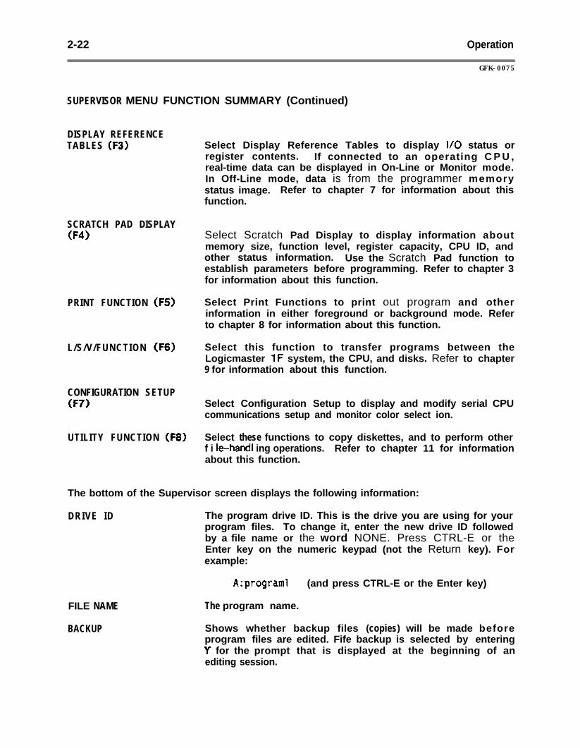
2-22 Operation
GFK-0075
SUPERVISOR MENU FUNCTION SUMMARY (Continued)
DISPLAY REFERENCETABLES (F3)
SCRATCH PAD DISPLAY(F4)
PRINT FUNCTION (FS)
L/S/V/FUNCTION (FS)
CONFIGURATION SETUP(F7)
UTILITY FUNCTION (F8)
Select Display Reference Tables to display l/O status orregister contents. If connected to an operating C P U ,real-time data can be displayed in On-Line or Monitor mode.In Off-Line mode, data is from the programmer memorystatus image. Refer to chapter 7 for information about thisfunction.
Select Scratch Pad Display to display information aboutmemory size, function level, register capacity, CPU ID, andother status information. Use the Scratch Pad function toestablish parameters before programming. Refer to chapter 3for information about this function.
Select Print Functions to print out program and otherinformation in either foreground or background mode. Referto chapter 8 for information about this function.
Select this function to transfer programs between theLogicmaster 1F system, the CPU, and disks. Refer to chapter9 for information about this function.
Select Configuration Setup to display and modify serial CPUcommunications setup and monitor color select ion.
Select these functions to copy diskettes, and to perform otherf i le-hand1 ing operations. Refer to chapter 11 for informationabout this function.
The bottom of the Supervisor screen displays the following information:
DRIVE ID The program drive ID. This is the drive you are using for yourprogram files. To change it, enter the new drive ID followedby a file name or the word NONE. Press CTRL-E or theEnter key on the numeric keypad (not the Return key). Forexample:
FILE NAME
BACKUP
A:programl (and press CTRL-E or the Enter key)
The program name.
Shows whether backup files (copies) will be made beforeprogram files are edited. Fife backup is selected by enteringY for the prompt that is displayed at the beginning of anediting session.
Operation
GFK-0075
2-23
I
LOADING PROGRAM FILES FROM THE SUPERVISOR MENU
Program files can be loaded into Logicmaster IF programmer memory using theLoad/Store/Verify function, or directly from the Supervisor menu. To load program filesfrom the Supervisor menu, follow these steps:
1 . Be sure that the file is present on the default drive (hard disk or diskette).
2 . If the drive ID does not show the drive where the program files are located, changeit. To enter a drive ID, type it into the work area and press CTRL-E or the Enterkey .
3 . Enter the program file name. Type the basic program file name, not including a filename extension, into the work area. For example:
PROGRAM 1
Then press CTRL-E or the Enter key.
4 . Press and hold the ALT key; then press the L key. All files with the file nameentered will be loaded into programmer memory. The message BUSY is displayed onthe screen until the files are loaded. If an error occurs, a message is displayed andthe loading is aborted.
Refer to chapter 9 for information on using the Load/Store/Verify function to load files.
NAMING THE PROGRAM
YOU should enter a program name before leaving Supervisor level to edit, display, or printa program. The name is retained until a new program is loaded, until the name iscanceled by entering the word T’NONE’V, or until power is removed from the system.
If no name is entered, the system can develop programs or monitor the CPU, butannotation cannot be used or displayed. In addition, without a program name, displayformats will not be saved because there will be no files to place them in. Finally, if noprogram name has been specified before editing a program, the system is unable to savethe edits automatically. Edits will be saved in programmer memory only. If power goesoff during editing, the work you have done will be lost. Therefore, you should alwaysenter the program name before leaving the Supervisor level.
A program name may have up to 8 characters. Do not use the following reserved words inprogram names: NONE, CON, NUL, PRN, AUX, COMl, COM2, LPTl, LPT2, LPT3. ’
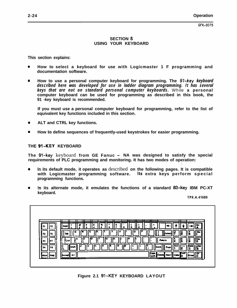
2-24 Operation
GFK-0075
SECTION 5USING YOUR KEYBOARD
This section explains:
0 How to select a keyboard for use with Logicmaster 1 F programming anddocumentation software.
0 How to use a personal computer keyboard for programming. The 974ey keyboarddescribed here was developed for use in ladder diagram programming. lt has severalkeys that are not on standard personal computer keyboards. While a personalcomputer keyboard can be used for programming as described in this book, the91 -key keyboard is recommended.
If you must use a personal computer keyboard for programming, refer to the list ofequivalent key functions included in this section.
0 ALT and CTRL key functions.
0 How to define sequences of frequently-used keystrokes for easier programming.
THE 9%KEY KEYBOARD
The St-key keyboard from GE Fanuc - NA was designed to satisfy the specialrequirements of PLC programming and monitoring. It has two modes of operation:
.
0 In its default mode, it operates as described on the following pages. It is compatiblewith Logicmaster programming software. Its extra keys perform s p e c i a lprogramming functions.
0 In its alternate mode, it emulates the functions of a standard 83.key IBM PC-XTkeyboard.
TPK.A.41680
Figure 2.1 9%KEY KEYBOARD LAYOUT
Operation 2-25
FUNCTIONS OF THE 9%KEY KEYBOARD
Typewriter Keys
The central area of the keyboard includes the typewriter keys, in standard QWERTYlayout. All of these keys will repeat their functions when held down.
The central area of the keyboard also includes these keys:
SUPRV The Supervisor key returns the display to the Supervisor menu.
TAB The Tab key works like a standard typewriter Tab key. Tabstops are set every 8 characters.
CTRL The Control key, when pressed at the same time as anotherkey, controls the execution of a function or command. Thefunction performed depends on the software.
I/\ The Backslash key types a backslash character, or a splitvertical bar when shifted.
ACCEPT The Accept key (or CTRL-A) is used to verify and accept anoperation, such as a ladder diagram run entry in the EditProgram function.
ALT
CAPS LOCK
The Alternate key, when pressed at the same time as anotherkey, controls the execution of a function or command. Referto the heading “ALT Key Functions” in this section for moreinformation.
The Caps Lock key locks the characters A through 2 intouppercase letters. It does not lock in the shifted functions ofother keys. .
Left Keypad
The keypad on the left includes keys Iabelled Fl through F8. The functions of these keysare controlled by Logicmaster 1F software. The currently-active functions are alwaysdisplayed at the bottom of the screen. The left keypad also includes these keys:
ABORT The Abort key (or F9) is. used to end the current operation.
HELP The Help key (or FlO) is used to display the Help screenassociated with the current operation taking place in thesoftware.
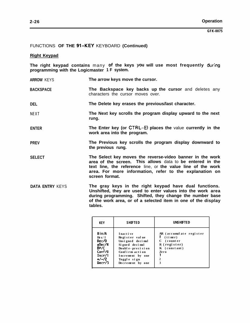
2-26 Operation
GFK-0075
FUNCTIONS OF THE 9%KEY KEYBOARD (Continued)
Right Keypad
The right keypad contains many of the keys YOU will use most frequently duringprogramming with the Logicmaster 1 F system.
ARROW KEYS The arrow keys move the cursor.
BACKSPACE The Backspace key backs up the cursor and deletes anycharacters the cursor moves over.
DEL The Delete key erases the previous/last character.
NEXT The Next key scrolls the program display upward to the nextrung.
ENTER The Enter key (or CTRL-E) places the value currently in thework area into the program.
PREV The Previous key scrolls the program display downward tothe previous rung.
SELECT The Select key moves the reverse-video banner in the workarea of the screen. This allows data to be entered in thetext line, the reference line, or the value line of the workarea. For more information, refer to the explanation onscreen format.
DATA ENTRY KEYS The gray keys in the right keypad have dual functions.Unshifted, they are used to enter values into the work areaduring programming. Shifted, they change the number baseof the work area, or of a selected item in one of the displaytables.
KEY SHIFTED UNSHIFTED
B i n / A Inactive AR (accumulate registerHex/I Register value T (timer)Dee/O Unsigned decimal C (counter&ec/R Signed decimal R (register)DP/C Double-precision K (constant)ConffO Confirm action Zerofncr/l Increment by one 1+/-/2 Toggle sign 2Decrf3 Decrement by one 3
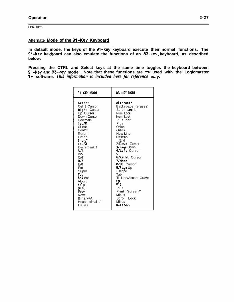
Operation 2-27
GFK-0075
Alternate Mode of the 9%Key Keyboard
In default mode, the keys of the 9Gkey keyboard execute their normal functions. The91.kev kevboard can also emulate the functions of an 83.kev keyboard, as describedbelow: ’ _
#
Pressing the CTRL and Select keys at the same time toggles91.key and 83.key mode. Note that these functions are not used1F software. This information is included here for reference on/v.
the keyboard betweenwith the Logicmaster
9bKEY MODE 830KEY MODE
AcceptCef t CursorRight CursorUp CursorDown CursorDecimal/ODee/RCl earConf/OReturnEnterIncr/l+/-/2Decrement/3A / 4B/5C/6D/7E/8F/9SuprvlabSe1 ectAbortHe1 pDP/CPrevNextBinary/AHexadecimal /IDelete
Al ternateBackspace (erases)Scroll Lot kNum LockNum LockPlus barPlusO/InsO/InsNew LineDelete/.1 /EndZ/Down Cursor3/Page Down4/Left Cursor56/Right Cursor7/Home8/Up Cursorg/Page UpEscapeTabTi 1 de/Accent GraveF9F10PlusPrint Screen/*MinusScroll LockMinusDe7 ete/.
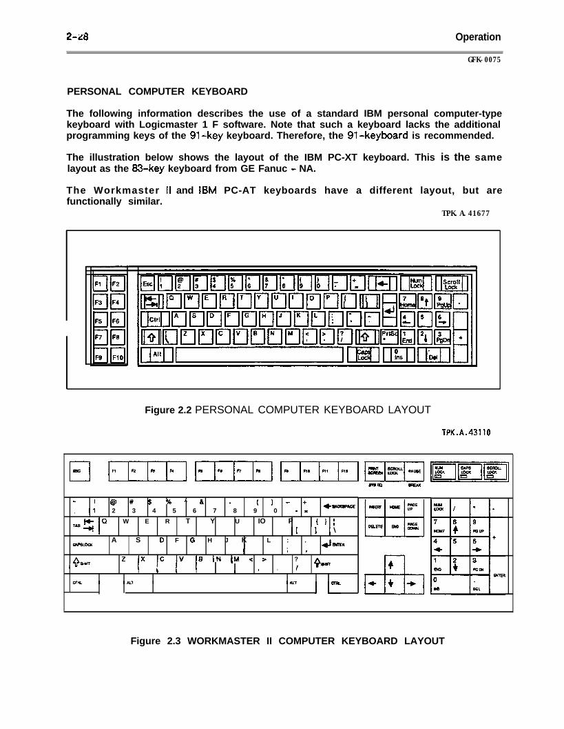
248 Operation
GFK-0075
PERSONAL COMPUTER KEYBOARD
The following information describes the use of a standard IBM personal computer-typekeyboard with Logicmaster 1 F software. Note that such a keyboard lacks the additionalprogramming keys of the 91-key keyboard. Therefore, the 91.keyboard is recommended.
The illustration below shows the layout of the IBM PC-XT keyboard. This is the samelayout as the 83-key keyboard from GE Fanuc - NA.
The Workmaster Ii and IBM PC-AT keyboards have a different layout, but arefunctionally similar.
TPK.A.41677
Figure 2.2 PERSONAL COMPUTER KEYBOARD LAYOUT
TPK.A.43110
z ! @ # $ % A & l ( ) - +!l 2 3 4 5 6 7 8 9 0 - -
a-E.
Q W E R T Y U IO P { ) :J _I _\
A S 0 F G H J K L : .eAPsLocK . eJ-
m e
CL-8 SN pdl < > ?
4-I c I /I m .
Figure 2.3 WORKMASTER II COMPUTER KEYBOARD LAYOUT
Operation 2-29
GFK-0075
FUNCTIONS OF THE PERSONAL COMPUTER KEYBOARD
Typewriter Keys
The central area of the keyboard includes the typewriter keys, in standard QWERTYlayout. All of these keys will repeat their functions when held down.
The central area of the keyboard also includes these keys:
ESC The Escape key emulates the function of the Supervisor key.It returns the display to the Supervisor menu.
CTRL The Control key, when pressed at the same time as anotherkey, controls the execution of a function or command. Thefunction performed depends on the software.
I/\ The Backslash key types a backslash character, or a splitvertical bar when shifted.
ALT The Alternate key, when pressed at the same time as anotherkey, controls the execution of a function or command. Referto the heading “ALT KEY FUNCTIONS” in this section.
* / PRT SC The Print Screen key can be used to print out a copy of whatis currently displayed on the screen. The printing parametersmust previously have been established, as described in thismanual. Print Screen is a shifted function.
CAPS LOCK - The Caps Lock key locks the characters A through 2 intouppercase letters. It does not lock in the shifted functions ofother keys.
Left Keypad
The keypad on the left includes keys Iabelled Fl through FlO. The functions of these keysare controlled by Logicmaster 1F software. Keys Fl through F8 function as shown by thelabels that are displayed on the bottom of the screen.
F9 functions as the Abort key. It is used to end the currentoperation.
FlO functions as the Help key. It is used to display the Helpscreen associated with the current operation taking place inthe software.
2-30 Opetation
GfK-0075
FUNCTIONS OF THE PERSONAL COMPUTER KEYBOARD (Continued)
Right Keypad
The right keypad contains many of the keys you will use most frequently duringprogramming with the Logicmaster 1 F system.
NUM LOCK The Num Lock key locks thetheir Qpper*’ functions. Forkey on, the cursor keys canprinted on the keys.
keys in the numeric keypad intoexample, with the Num Lockbe used to enter the numbers
ARROW KEYS With Num Lock off, the arrow I keys move the cursor.
BACKSPACE When used with Logicmaster 1F software, the Backspace keyemulates the O/Dee key on the 91.key keyboard. This key isused to enter a letter 0 (for output) in the center line of thework area, or to change the bottom line of the work area todecimal format.
DEL The Delete key erases the last character entered.
INS/O (Num Lock Off) With Num Lockoff, the Ins/O key functions as the Next key.It scrolls the program display upward to the next rung. WithNum Lock on, this key enters a zero.
PGDN/3 (Num Lock Off ) With Num Lock off, this key functions as the Enter key (orCTRL-E). It places the value currently in the work area intothe program. With Num Lock on, this key enters a number 3in the work area.
PRT SC / *
4 s
Unshifted, the Print Screen/* key functions as the Previouskey. It scrolls the program display downward to the previousrung l
Unshifted, the Tilde key functions as the Select key. Itmoves the reverse-video banner in the work area of thescreen. This allows data to be entered in the text line, thereference line, or the value line of the work area. For moreinformation, refer to section 4, SCREEN FORMAT.
For more information, a&et to HIP list of key functions on the next page.
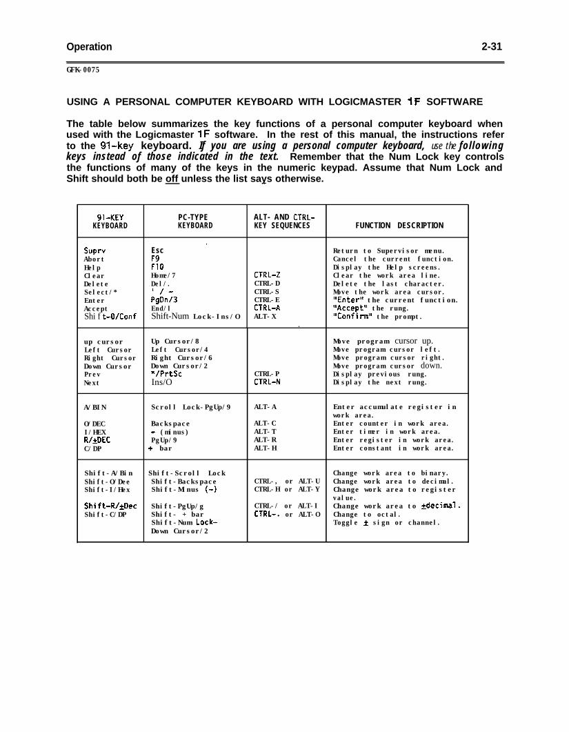
Operation 2-31
GFK-0075
USING A PERSONAL COMPUTER KEYBOARD WITH LOGICMASTER 1F SOFTWARE
The table below summarizes the key functions of a personal computer keyboard whenused with the Logicmaster 1F software. In the rest of this manual, the instructions referto the 91-key keyboard. If you are using a personal computer keyboard, use the followingkeys instead of those indicated in the text. Remember that the Num Lock key controlsthe functions of many of the keys in the numeric keypad. Assume that Num Lock andShift should both be off unless the list says otherwise.
9bKEY PC-TYPEKEYBOARD KEYBOARD
ALT- AND CTRL-KEY SEQUENCES FUNCTION DESCRIPTION
*Sup Esc Return to Supervisor menu.Abort F9 Cancel the current function.Help FlO Display the Help screens.Clear Home/7 CTRL-2 Clear the work area line.Delete Del/. CTRL-D Delete the last character.Select/* '/- CTRL-S Move the work area cursor.Enter PgDn/S CTRL-E "Enter" the current function.Accept End/l CTRL-A "Accept" the rung.Shi f t-WConf Shift-Num Lock-Ins/O ALT-X "Confirm*' the prompt.
*
up cursor Up Cursor/8 Move program cursor up.Left Cursor Left Cursor/4 Move program cursor left.Right Cursor Right Cursor/6 Move program cursor right.Down Cursor Down Cursor/2 Move program cursor down.Prev VPrtSc CTRL-P Display previous rung.Next Ins/O CTRt-N Display the next rung.
A/BIN
O/DECI/HEXR/&DECC/DP
Scroll Lock-PgUp/9 ALT-A Enter accumulate register inwork area.
Backspace ALT-C Enter counter in work area.- (minus) ALT-T Enter timer in work area.PgUp/9 ALT-R Enter register in work area.
G + bar ALT-H Enter constant in work area.
Shift-A/Bin q Shift-Scroll LockShift-O/Dee Shift-BackspaceShift-I/Hex Shift-Minus (0)
Shift-R/kDec Shift-PgUp/gShift-C/DP Shift- + bar
Shift-Num Lock-Down Cursor/2
Change work area to binary.CTRL-, or ALT-U Change work area to decimal.CTRL-H or ALT-Y Change work area to register
value.CTRL-/ or ALT-I Change work area to *decimal.CTRL-. or ALT-O Change to octal.
Toggle + sign or channel.
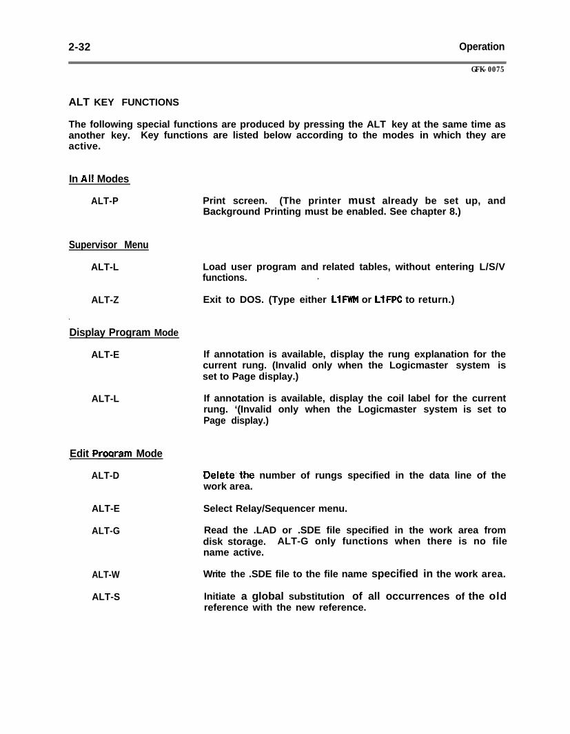
2-32 Operation
GFK-0075
ALT KEY FUNCTIONS
The following special functions are produced by pressing the ALT key at the same time asanother key. Key functions are listed below according to the modes in which they areactive.
In Ail Modes
ALT-P Print screen. (The printer must already be set up, andBackground Printing must be enabled. See chapter 8.)
Supervisor Menu
ALT-L
ALT-Z
.
Display Program Mode
ALT-E
ALT-L
Edit Prowam Mode____
ALT-D
ALT-E Select Relay/Sequencer menu.
ALT-G Read the .LAD or .SDE file specified in the work area fromdisk storage. ALT-G only functions when there is no filename active.
ALT-W
ALT-S
Load user program and related tables, without entering L/S/Vfunctions. .
Exit to DOS. (Type either LlFWM or LlFPC to return.)
If annotation is available, display the rung explanation for thecurrent rung. (Invalid only when the Logicmaster system isset to Page display.)
If annotation is available, display the coil label for the currentrung. ‘(Invalid only when the Logicmaster system is set toPage display.)
Delete?he number of rungs specified in the data line of thework area.
Write the .SDE file to the file name specified in the work area.
Initiate a global substitution of all occurrences of the oldreference with the new reference.
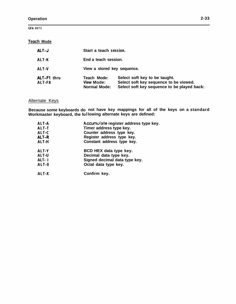
Operation 2-33
GFK-0075
Teach Mode
ALT-3
ALT-K
ALT-V
ALT-Fl thruALT-F8
Alternate Keys
Because some keyboards doWorkmaster keyboard, the fo
ALT-A A
Start a teach session.
End a teach session.
View a stored key sequence.
Teach Mode: Select soft key to be taught.View Mode: Select soft key sequence to be viewed.Normal Mode: Select soft key sequence to be played back:
ALT-TALT-CALT-RALT-H
ALT-YALT-UALT- IALT-0
ALT-X
not have key mappings for all of the keys on a standardlowing alternate keys are defined:
xumulate register address type key._ _Timer address type key.Counter address type key.Register address type key.Constant address type key.
BCD HEX data type key.Decimal data type key.Signed decimal data type key.Octal data type key.
Confirm key.
2-34 Operation
GFK-0075
DEFINING SEQUENCES OF FREQUENTLY-USED KEYSTROKES (TEACH MODE)
Loqicmaster 1 F software allows you to program the soft keys (Fl through F8) tore&;rze sequences of key strokes. These V’mini-programs” al low frequently used keystrokes to be duplicated with only two key presses. For example, an edit session may bestored and then reproduced by pressing only two keys.
The key strokes are stored on any diskette in the default drive specified on the Supervisormenu.
] CAUTION [
Do not include keystrokes representing Pause, Resume, orAbort functions. Use of these keys m a y lead tounpredictable results when using the customized function.
The keystrokes that make up the customized function will be stored in the file Fx.DEF,where x is the number of the function key. A diskette can store up to eight of thesecustomized key functions - one for each key Fl through F8. Additional key functions canbe stored on other diskettes.
CREATING A CUSTOMIZED KEY FUNCTION
Follow the steps below to create a customized key function.
1 .
2 .
3 .
4 .
5 .
6 .
Confirm that a diskette is in the default drive.
Place the system in the exact mode and condition for the function to begin. Thesystem will remember this configuration, and will not allow the function to be usedlater unless the configuration matches.
It is best to begin the function at a basic level, such as Supervisor Menu, Print MainMenu, or Edit Program. When you are at the exact point for the function to begin,press and hold the ALT key and press the 3 key. This places the system in Teachmode.
Press and hold the ALT key and press the function key (Fl - F8) that will control thefunction. The new function will replace the original function of the key in thatlocation, so choose either an unused key or one you will not need.
To create the function, you can use any succession of keystrokes. Do not includekeystrokes for Pause, Resume, or Abort. The system records every keystroke untilthe ALT and K keys are pressed.
While the system is in Teach mode, it records all keystrokes except those that can beused to end the function. To end the function normally and store it in the Fx.DEFfile, press the ALT and K keys.
If an error condition is encountered during the playback of the stored sequence, thesequence is halted. Pressing any key causes an error message to be displayed.Respond to the prompt to either resume or terminate the key sequence.
Operation
GFK-0075
2-35
USING A DEFINED KEY FUNCTION
After a key function is defined and stored in the Fx.DEF file, it can be recalled b ypressing the ALT key together with the Fl - F8 key assigned to the function.
For the function to be correct, the screen display and function key assignments must bethe same as when the function was created. Cursor position, work area content, and dataon the screen may not be the same. Be sure to check these before using the function.
When the function is selected, using the ALT key and the assigned function key, the -system repeats the keystrokes very rapidly.
During this “playback” of the function, the only keyboard input recognized is the Abortkey. Press F9 or the Abort key to stop the function. Pressing F9 or Abort does notremove the part of the function that has already been performed.
lf an error condition is encountered during the execution of the function, a message isdisplayed and the system automatically aborts the function.
DISPLAYING AND PRINTING A DEFINED KEY FUNCTION (VIEW MODE)
The system stores the defined function in the .DEF file as a list of the keystrokes thatwere executed for the function. This list can be displayed on the screen, and printedusing the Print Screen command (ALT-P).
One page of the View Mode screen can list approximately 500 to 600 keystrokes,separated by commas. If the entire function list does not fit on one screen in View mode,press the NEXT key to view additional screens.
The first key listed is the function key which has been redefined. In this example, it isF6. The next two numbers represent the display ‘level where the function was defined.The displays represented by these numbers are listed on the following pages.
On the next line, the listing of keystrokes begins.
0 Capital letters indicate that the shifted and unshifted values of the key areessentially equal.
0 The caret (&) character indicates a press of the CTRL key.0 An exclamation point (!) indicates a press of the ALT key.0 A quotation mark (!I) character indicates a press of the shift key.0 The number symbol (#) is displayed before numbers input from the numeral keypad.
No number symbol is displayed before numbers input from the ASCII keyboard.
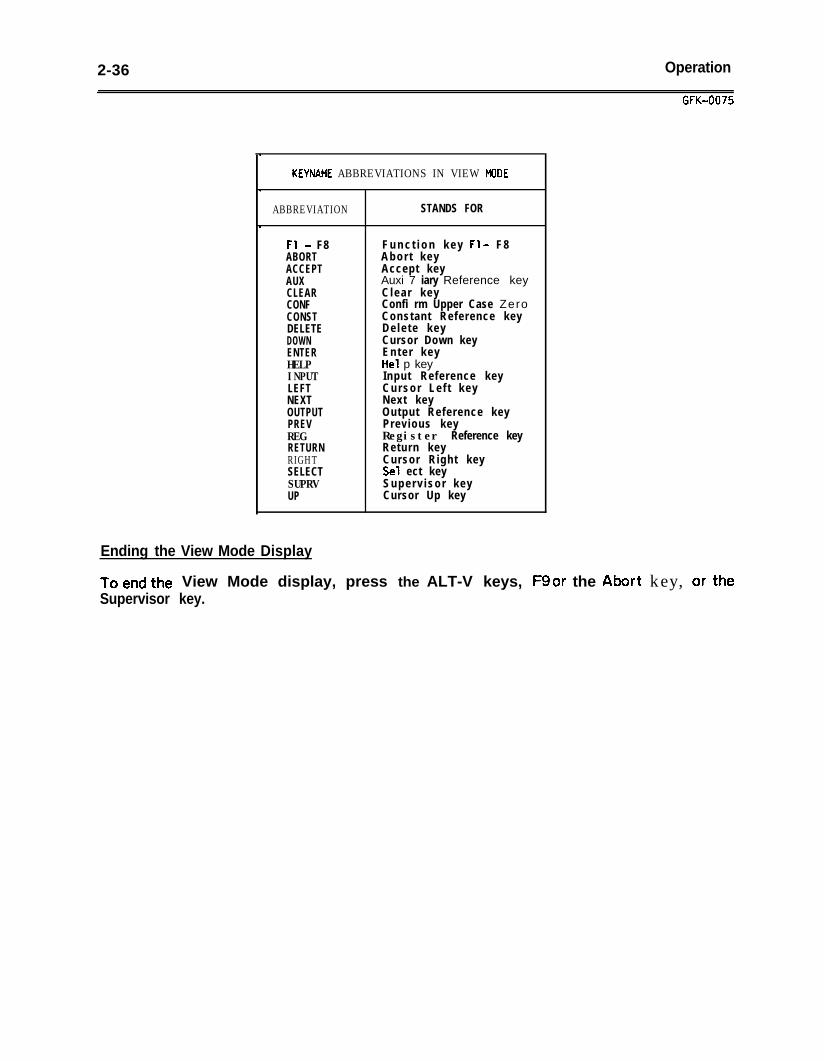
2-36 Operation
Ending the View Mode Display
GFK-0075
KEYNAME ABBREVIATIONS IN VIEW MODE
ABBREVIATION STANDS FOR
Fl - F8ABORTACCEPTAUXCLEARCONFCONSTDELETEDOWNENTERHELPINPUTLEFTNEXTOUTPUTPREVREGRETURNRIGHTSELECTSUPRVUP
F u n c t i o n k e y Fl - F 8Abor t keyAccept keyAuxi 7 iary Reference keyClear keyConfi rm Upper Case ZeroConstant Reference keyDe le te keyCursor Down keyEnter keyHe1 p keyInput Reference keyCursor Le f t keyNext keyOutput Reference keyPrevious keyRegister Reference keyReturn keyCursor Right keySe1 ect keySuperv isor keyCursor Up key
To end the View Mode display, press the ALT-V keys, F9 or the Abort key, or theSupervisor key.
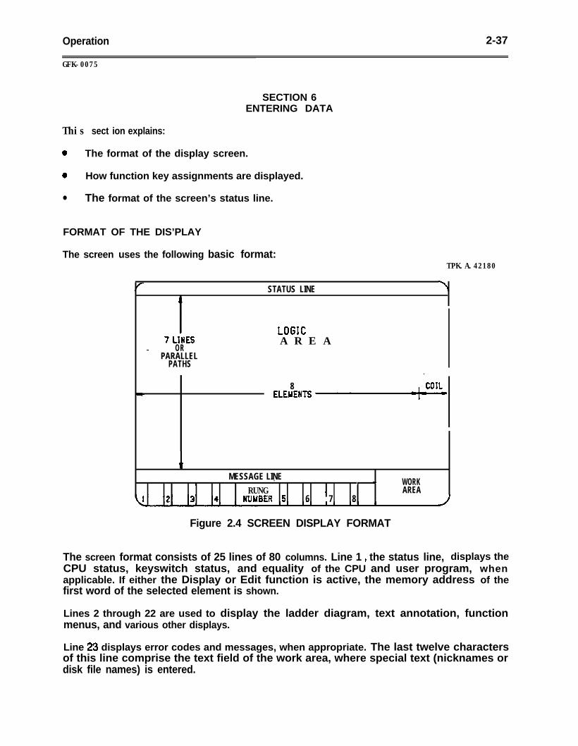
Operation 2-37
GFK-0075
SECTION 6ENTERING DATA
This sect ion explains:
0 The format of the display screen.
0 How function key assignments are displayed.
l The format of the screen’s status line.
FORMAT OF THE DIS’PLAY
The screen uses the following basic format:TPK.A.42180
STATUS LINE\
7 LIMESOR
A R E AePARALLEL
PATHS.
8ELEUENTS
MESSAGE LINE. ‘1)1 1 WORKRUNG 4 AREA
WUUBER 5 6 7 8
Figure 2.4 SCREEN DISPLAY FORMAT
The screen format consists of 25 lines of 80 columns. Line 1 9 the status line, displays theCPU status, keyswitch status, and equality of the CPU and user program, whenapplicable. If either the Display or Edit function is active, the memory address of thefirst word of the selected element is shown.
Lines 2 through 22 are used to display the ladder diagram, text annotation, functionmenus, and various other displays.
Line 23 displays error codes and messages, when appropriate. The last twelve charactersof this line comprise the text field of the work area, where special text (nicknames ordisk file names) is entered.
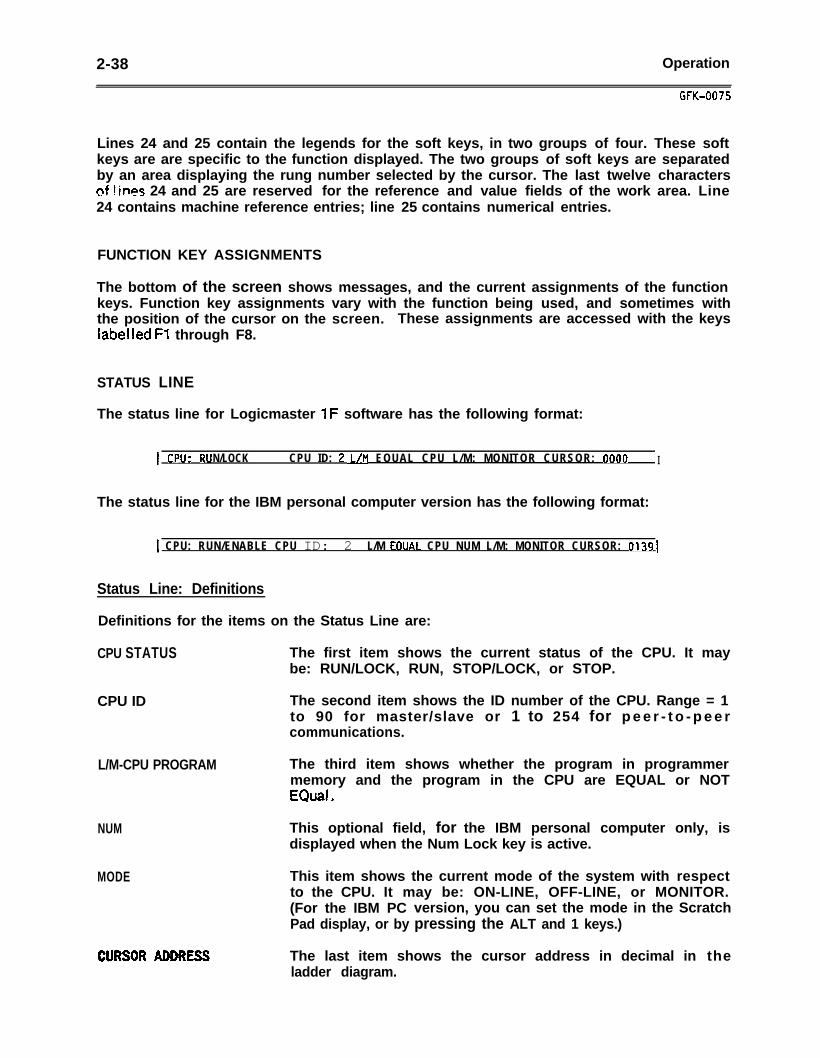
2-38 Operation
GFK-0075
Lines 24 and 25 contain the legends for the soft keys, in two groups of four. These softkeys are are specific to the function displayed. The two groups of soft keys are separatedby an area displaying the rung number selected by the cursor. The last twelve characterscf Vines 24 and 25 are reserved for the reference and value fields of the work area. Line24 contains machine reference entries; line 25 contains numerical entries.
FUNCTION KEY ASSIGNMENTS
The bottom of the screen shows messages, and the current assignments of the functionkeys. Function key assignments vary with the function being used, and sometimes withthe position of the cursor on the screen. These assignments are accessed with the keyslabelled Fl through F8.
STATUS LINE
The status line for Logicmaster 1F software has the following format:
.I CPU* RU N/LOCK CPU ID: ? JJM EOUAL CPU L/M: MONITOR CURSOR: 0000 I
The status line for the IBM personal computer version has the following format:
1 CPU: RUN/ENABLE CPU ID: 2 L/M EOUAI. CPU NUM L/M: MONITOR CURSOR: 0139 [
Status Line: Definitions
Definitions for the items on the Status Line are:
CPU STATUS The first item shows the current status of the CPU. It maybe: RUN/LOCK, RUN, STOP/LOCK, or STOP.
CPU ID The second item shows the ID number of the CPU. Range = 1to 90 for master/slave or 1 to 254 for p e e r - t o - p e e rcommunications.
L/M-CPU PROGRAM The third item shows whether the program in programmermemory and the program in the CPU are EQUAL or NOTEQuaE *
NUM
MODE
This optional field, for the IBM personal computer only, isdisplayed when the Num Lock key is active.
This item shows the current mode of the system with respectto the CPU. It may be: ON-LINE, OFF-LINE, or MONITOR.(For the IBM PC version, you can set the mode in the ScratchPad display, or by pressing the ALT and 1 keys.)
The last item shows the cursor address in decimal in theladder diagram.
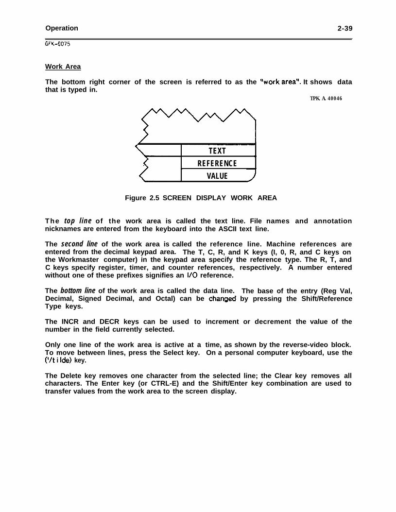
Operation 2-39
Work Area
The bottom right corner of the screen is referred to as the “work area”. It shows datathat is typed in.
TPK.A.40046
The top line of the work area is called the text line. File names and annotationnicknames are entered from the keyboard into the ASCII text line.
TEXT IREFERENCEI
VALUE
Figure 2.5 SCREEN DISPLAY WORK AREA
The second line of the work area is called the reference line. Machine references areentered from the decimal keypad area. The T, C, R, and K keys (I, 0, R, and C keys onthe Workmaster computer) in the keypad area specify the reference type. The R, T, andC keys specify register, timer, and counter references,without one of these prefixes signifies an I/O reference.
respectively. -& number entered
The bottom line of the work area is called the data line.Decimal, Signed Decimal, and Octal) can be chanaedType keys. -
The INCR and DECR keys can be used tonumber in the field currently selected.
Only one line of the work area is active at aTo move between lines, press the Select key.(‘/t i Ide) key.
The base of the entry (Reg Val,by pressing the Shift/Reference
increment or decrement the value of the
time, as shown by the reverse-video block.On a personal computer keyboard, use the
The Delete key removes one character from the selected line; the Clear key removes allcharacters. The Enter key (or CTRL-E) and the Shift/Enter key combination are used totransfer values from the work area to the screen display.
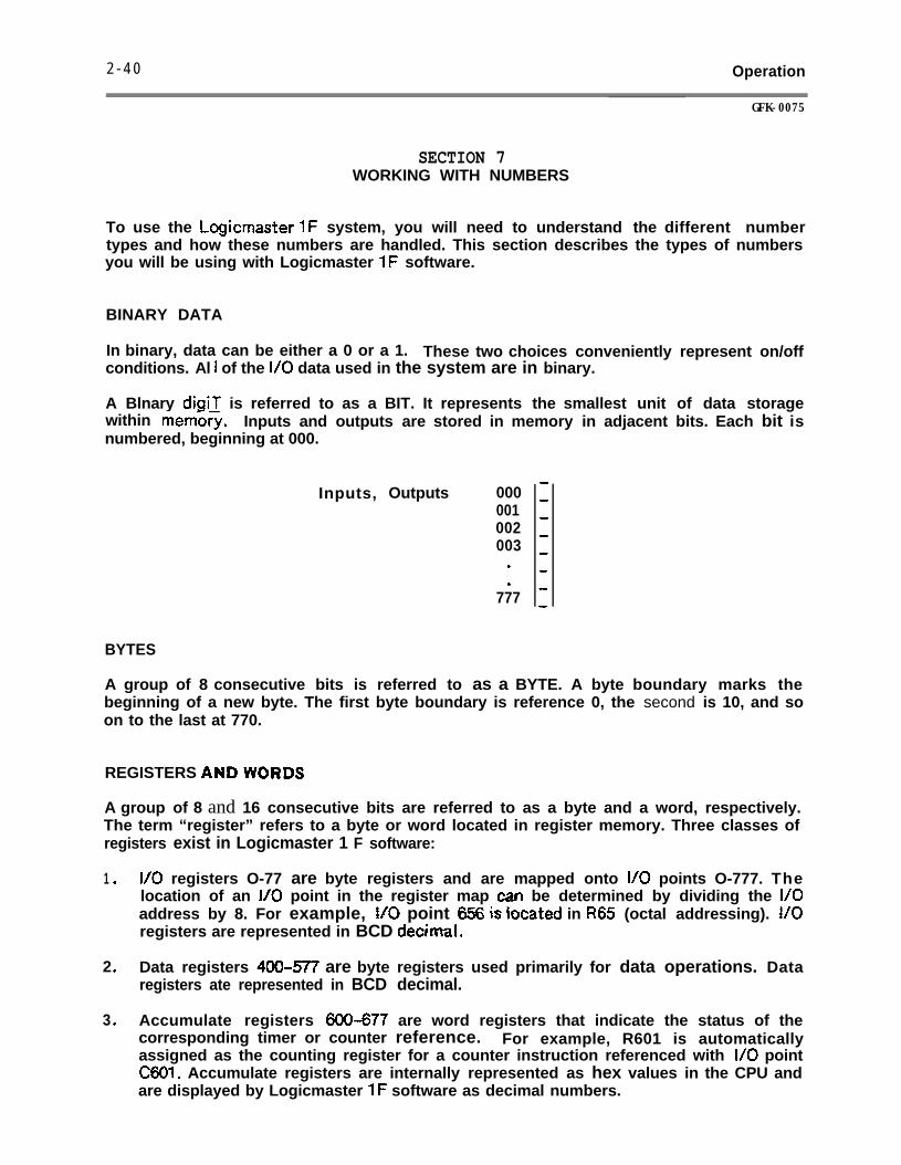
2 - 4 0 Operation
GFK-0075
SECTION 7WORKING WITH NUMBERS
To use the Logicmastet 1F system, you will need to understand the different numbertypes and how these numbers are handled. This section describes the types of numbersyou will be using with Logicmaster 1F software.
BINARY DATA
In binary, data can be either a 0 or a 1. These two choices conveniently represent on/offconditions. Al I of the l/O data used in the system are in binary.
A Blnary digii is referred to as a BIT. It represents the smallest unit of data storagewithin memory. Inputs and outputs are stored in memory in adjacent bits. Each bit isnumbered, beginning at 000.
Inputs, Outputs 000001002003
.
.777
BYTES
A group of 8 consecutive bits is referred to as a BYTE. A byte boundary marks thebeginning of a new byte. The first byte boundary is reference 0, the second is 10, and soon to the last at 770.
REGISTERS ANDWORDS
A group of 8 and 16 consecutive bits are referred to as a byte and a word, respectively.The term “register” refers to a byte or word located in register memory. Three classes ofregisters exist in Logicmaster 1 F software:
1 . I/O registers O-77 are byte registers and are mapped onto I/O points O-777. Thelocation of an I/O point in the register map can be determined by dividing the I/Oaddress by 8. For example, t/0 point 656 iis Cocated in R65 (octal addressing). I/Oregisters are represented in BCD decimal.
2 . Data registers 400-577 are byte registers used primarily for data operations. Dataregisters ate represented in BCD decimal.
3 . Accumulate registers 600-677 are word registers that indicate the status of thecorresponding timer or counter reference. For example, R601 is automaticallyassigned as the counting register for a counter instruction referenced with l/O pointC601. Accumulate registers are internally represented as hex values in the CPU andare displayed by Logicmaster 1F software as decimal numbers.
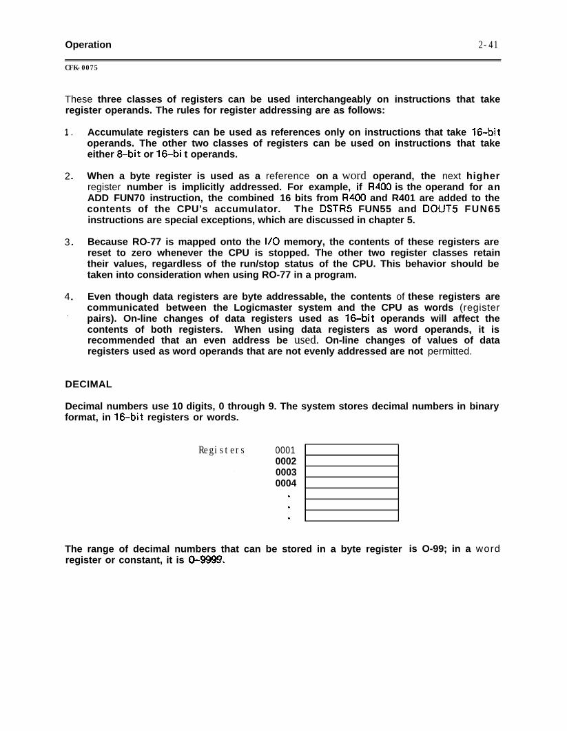
Operation
CFK-0075
2-41
These three classes of registers can be used interchangeably on instructions that takeregister operands. The rules for register addressing are as follows:
1 l
2 .
3 .
4 .
.
Accumulate registers can be used as references only on instructions that take 16.bitoperands. The other two classes of registers can be used on instructions that takeeither 8-bit or 16.bi t operands.
When a byte register is used as a reference on a word operand, the next higherregister number is implicitly addressed. For example, if R400 is the operand for anADD FUN70 instruction, the combined 16 bits from R4CKI and R401 are added to thecontents of the CPU’s accumulator. The DSTRS FUN55 and DOUTS FUN65instructions are special exceptions, which are discussed in chapter 5.
Because RO-77 is mapped onto the I/O memory, the contents of these registers arereset to zero whenever the CPU is stopped. The other two register classes retaintheir values, regardless of the run/stop status of the CPU. This behavior should betaken into consideration when using RO-77 in a program.
Even though data registers are byte addressable, the contents of these registers arecommunicated between the Logicmaster system and the CPU as words (registerpairs). On-line changes of data registers used as 160bit operands will affect thecontents of both registers. When using data registers as word operands, it isrecommended that an even address be used. On-line changes of values of dataregisters used as word operands that are not evenly addressed are not permitted.
DECIMAL
Decimal numbers use 10 digits, 0 through 9. The system stores decimal numbers in binaryformat, in 160bit registers or words.
Registers
‘.
0001000200030004
.
.
.
The range of decimal numbers that can be stored in a byte registerregister or constant, it is 0-9999.
is O-99; in a word
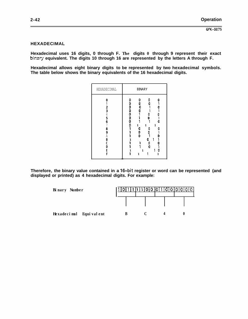
2-42 Operation
GFK-0075
HEXADECIMAL
Hexadecimal uses 16 digits, 0 through F. The digits 0 through 9 represent their exactbir.zr;l equivalent. The digits 10 through 16 are represented by the letters A through F.
Hexadecimal allows eight binary digits to be represented by two hexadecimal symbols.The table below shows the binary equivalents of the 16 hexadecimal digits.
HEXADECIMAL BINARY
0 0 0 0 01 0 0 0 12 0 0 1 03 0 0 1 14 0 1 0 05 0 1 0 16 0 1 1 07 0 1 1 18 1 0 0 09 1 0 0 1A 1 0 1 0B 1 0 1 1C 1 1 0 0D 1 1 0 1E 1 1 1 0F 1 1 1 1
Therefore, the binary value contained in a 16.bit register or word can be represented (anddisplayed or printed) as 4 hexadecimal digits. For example:
Binary Number
Hexadecimal Equivalent
I 1101111 llllOl0 OlllOlO olololo
B C 4 0
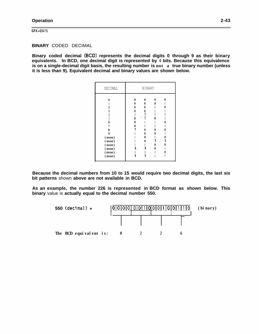
Operation 2-43
GFK-0075
BINARY CODED DECIMAL
Binary coded decimal (BCD) represents the decimal digits 0 through 9 as their binaryequivalents. In BCD, one decimal digit is represented by 4 bits. Because this equivalenceis on a single-decimal digit basis, the resulting number is not a true binary number (unlessit is less than 9). Equivalent decimal and binary values are shown below.
DECIMAL BINARY
0 0 0 0 01 0 0 0 12 0 0 1 03 0 0 1 14 0 1 0 05 0 7 0 16 0 1 1 07 0 1 1 18 1 0 0 09 1 0 0 1
(none) 1 0 1 0(none) 1 0 1 1(none) 1 1 0 0(none) b 1 0 1(none) 1 1 1 0(none) 1 1 t 1
Because the decimal numbers from 10 to 15 would require two decimal digits, the last sixbit patterns shown above are not available in BCD.
As an example, the number 226 is represented in BCD format as shown below. Thisbinary value is actually equal to the decimal number 550.
550 (decImalI = I olololo O[OlllO 0~0~1~0~0~1~1~0I _ I
(binary)
The BCD equivalent is: 0 2 2 6

Scratch Pad 3 - l
CHAPTER 3SCRATCH PAD
The Scratch Pad function is used to store and display information about the currentprogram in programmer memory, or about the CPU capabilities. Select the Scratch Padfunction in order to:
0 Change the ID number of the CPU.
0 Display the current CPU capabilities in On-Line or Monitor mode.
0 Compare the current CPU parameters with those stored for a program.
0 Select the functions to be used when programming in Off-Line mode.
When you are developing a program in Off-Line mode, establish the parameters inthe Scratch Pad before beginning. This will determine which functions are availableduring programming.
a Set up the current mode of the system (Off-Line, On-Line, or Monitor) for anIBM-compatible personal computer.
0 Start or stop the Data Communications Unit (DCU).
This chapter contains the following sections:
Section 1. Scratch Pad Display: Section 1 defines the entries on the Scratch Pad display.
Section 2. Editing the Scratch Pad Display: Section 2 explains how to change theScratch Pad entries for CPU ID, CPU memory size, number or registers available, CPUstatus, and function set.
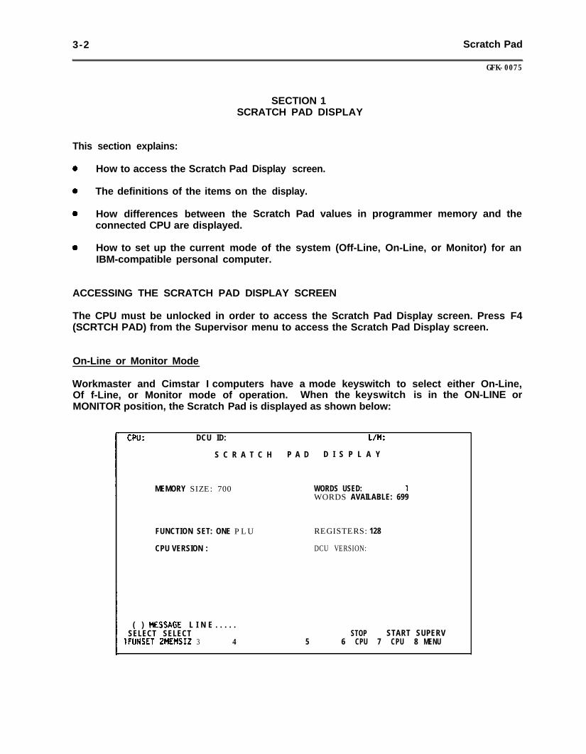
3-2 Scratch Pad
GFK-0075
SECTION 1SCRATCH PAD DISPLAY
This section explains:
0 How to access the Scratch Pad
* The definitions of the items on
0 How differences between theconnected CPU are displayed.
Display screen.
the display.
Scratch Pad values in programmer memory and the
0 How to set up the current mode of the system (Off-Line, On-Line, or Monitor) for anIBM-compatible personal computer.
ACCESSING THE SCRATCH PAD DISPLAY SCREEN
The CPU must be unlocked in order to access the Scratch Pad Display screen. Press F4(SCRTCH PAD) from the Supervisor menu to access the Scratch Pad Display screen.
On-Line or Monitor Mode
Workmaster and Cimstar I computers have a mode keyswitch to select either On-Line,Of f-Line, or Monitor mode of operation. When the keyswitch is in the ON-LINE orMONITOR position, the Scratch Pad is displayed as shown below:
CPU: DCU ID: L/M:
S C R A T C H P A D D I S P L A Y
MEMORY SIZE: 700 WORDS USED: 1WORDS AVAILABLE: 699
FUNCTION SET: ONE PLU
CPU VERSION :
REGISTERS: 128
DCU VERSION:
( ) HESSAGE L I N E . . . . .SELECT SELECT
1FlJNSET ZMEMSIZ 3 4 5STOP START SUPERV
6 CPU 7 CPU 8 MENU
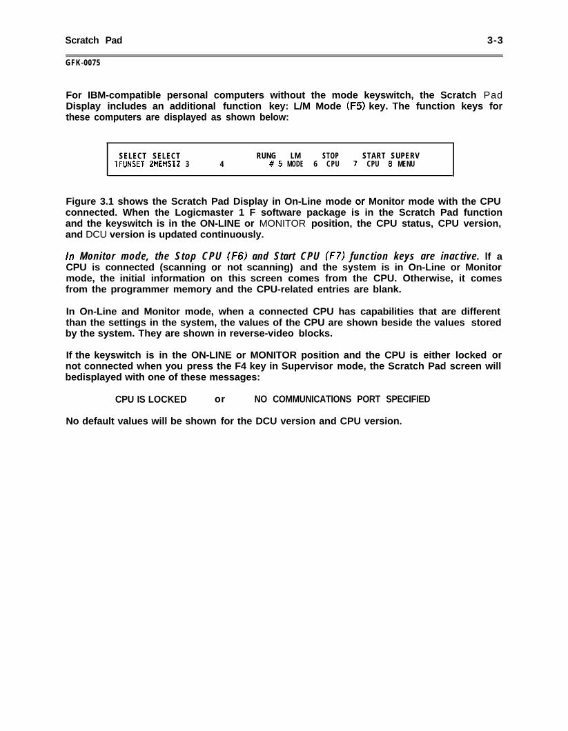
Scratch Pad 3-3
GFK-0075
For IBM-compatible personal computers without the mode keyswitch, the Scratch PadDisplay includes an additional function key: L/M Mode (F5) key. The function keys forthese computers are displayed as shown below:
SELECT SELECT RUNG LM STOP START SUPERV1FUNSET ZMEMSIZ 3 4 # 5 MODE 6 CPU 7 CPU 8 MENU
Figure 3.1 shows the Scratch Pad Display in On-Line mode or Monitor mode with the CPUconnected. When the Logicmaster 1 F software package is in the Scratch Pad functionand the keyswitch is in the ON-LINE or MONITOR position, the CPU status, CPU version,and DCU version is updated continuously.
In Monitor mode, the Stop CPU (F6) and Start CPU (f7) function keys are inactive. lf aCPU is connected (scanning or not scanning) and the system is in On-Line or Monitormode, the initial information on this screen comes from the CPU. Otherwise, it comesfrom the programmer memory and the CPU-related entries are blank.
In On-Line and Monitor mode, when a connected CPU has capabilities that are differentthan the settings in the system, the values of the CPU are shown beside the values storedby the system. They are shown in reverse-video blocks.
If the keyswitch is in the ON-LINE or MONITOR position and the CPU is either locked ornot connected when you press the F4 key in Supervisor mode, the Scratch Pad screen willbedisplayed with one of these messages:
CPU IS LOCKED or NO COMMUNICATIONS PORT SPECIFIED
No default values will be shown for the DCU version and CPU version.
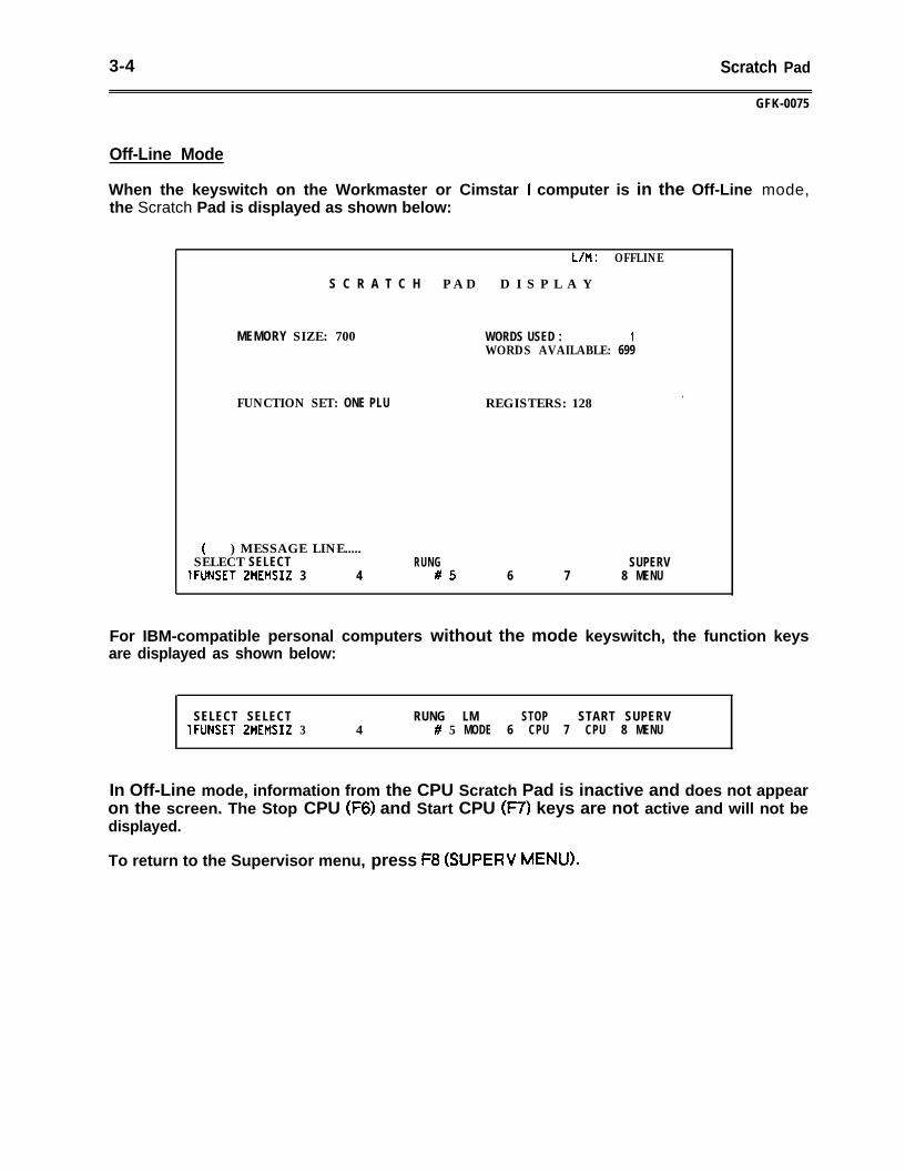
3-4 Scratch Pad
GFK-0075
Off-Line Mode
When the keyswitch on the Workmaster or Cimstar I computer is in the Off-Line mode,the Scratch Pad is displayed as shown below:
l/M : OFFLINE
S C R A T C H P A D D I S P L A Y
MEMORY SIZE: 700 WORDS USED : 1WORDS AVAILABLE: 699
FUNCTION SET: ONE PLU REGISTERS: 128.
( ) MESSAGE LINE.....SELECT SELECT
1FUNSET ZMEMSIZ 3 4RUNG
#5 6 7SUPERV
8 MENU
For IBM-compatible personal computers without the mode keyswitch, the function keysare displayed as shown below:
SELECT SELECT RUNG LM STOP START SUPERV1FUNSET ZMEMSIZ 3 4 # 5 MODE 6 CPU 7 CPU 8 MENU
In Off-Line mode, information from the CPU Scratch Pad is inactive and does not appearon the screen. The Stop CPU (F6) and Start CPU 07) keys are not active and will not bedisplayed.
To return to the Supervisor menu, press F8 (SUPERV MENU).
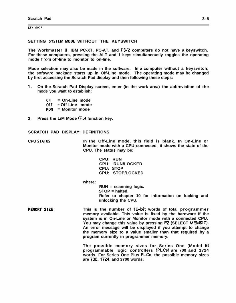
Scratch Pad 3-5
SETTING SYSTEM MODE WITHOUT THE KEYSWITCH
The Workmaster II, IBM PC-XT, PC-AT, and PSI2 computers do not have a keyswitch.For these computers, pressing the ALT and 1 keys simultaneously toggles the operatingmode f ram off-line to monitor to on-line.
Mode selection may also be made in the software. In a computer without a keyswitch,the software package starts up in Off-Line mode. The operating mode may be changedby first accessing the Scratch Pad display and then following these steps:
1 . On the Scratch Pad Display screen, enter (in the work area) the abbreviation of themode you want to establish:
ON = On-Line modeOFF = Off-Line modeMON = Monitor mode
2 . Press the L/M Mode (F5) function key.
SCRATCH PAD DISPLAY: DEFINITIONS
CPU STATUS In the Off-Line mode, this field is blank. In On-Line orMonitor mode with a CPU connected, it shows the state of theCPU. The status may be:
where:RUN = scanning logic.STOP = halted.Refer to chapter 10 for information on locking andunlocking the CPU.
This is the number of 160bit words of total programmer
CPU: RUNCPU: RUN/LOCKEDCPU: STOPCPU: STOP/LOCKED
memory available. This value is fixed by the hardware if thesystem is in On-Line or Monitor mode with a connected CPU.You may change this value by pressing F2 (SELECT MEMSIZ).An error message will be displayed if you attempt to changethe memory size to a value smaller than that required by aprogram currently in programmer memory.
The possible memory sizes for Series One (Model E)programmable logic controllers (PLcs) are 700 and 1724words. For Series One Plus PLCs, the possible memory sizesare 700,1724, and 3700 words.
3-6 Scratch Pad
GFK-0075
SCRATCH PAD DISPLAY: DEFINITIONS (Continued)
WORDS USED This entry shows the exact length of the current program, in16.bit words. (You can verify the words used for a particularprogram with the Logicmaster 1F programmer.)
WORDS AVAILABLE This entry shows the exact number of 16.bit words remainingfor program storage. WORDS AVAILABLE equals MEMORYSIZE minus WORDS USED.
FUNCTION SET
CPU VERSION
DCU VERS I ON
This entry shows the level of features available in the CPU.The possible .function sets are ONE (for Series One Model E)and ONE PLUS (for Series One Plus). Press Fl (SELECTFUNSET) to toggle between ONE and ONE PLUS. If theladder diagram program in memory contains logic usingfunctions not available with the function set selected, yourselection will not be accepted.
This entry shows the number of 8-bit storage locations(registers). In On-Line or Monitor mode, when connected to aCPU, this is the total number of registers available. You canchange this entry by changing the function set.
This entry is only displayed in On-Line or Monitor mode, witha CPU connected. It shows the revision level of the CPUsoftware.
This entry is also displayed only in On-Line or Monitor mode,with a CPU connected. It shows the revision level of the DataCommunications Unit (DCU).
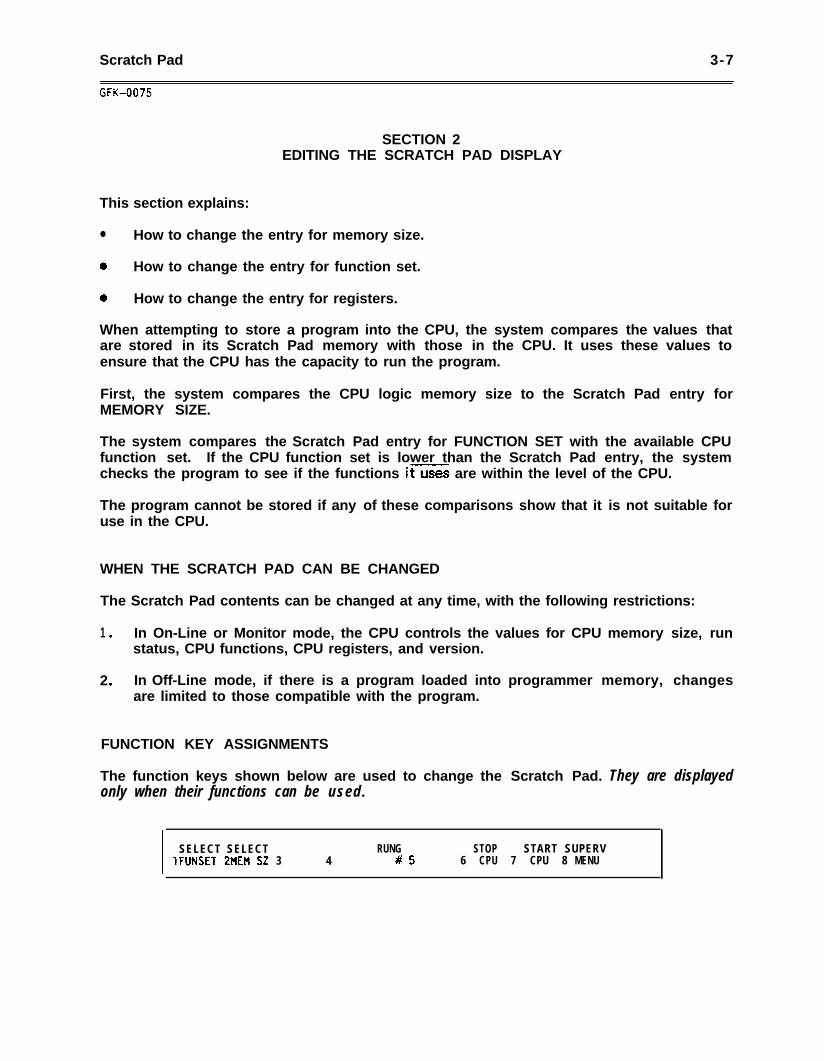
Scratch Pad 3-7
SECTION 2EDITING THE SCRATCH PAD DISPLAY
This section explains:
l How to change the entry for memory size.
0 How to change the entry for function set.
a How to change the entry for registers.
When attempting to store a program into the CPU, the system compares the values thatare stored in its Scratch Pad memory with those in the CPU. It uses these values toensure that the CPU has the capacity to run the program.
First, the system compares the CPU logic memory size to the Scratch Pad entry forMEMORY SIZE.
The system compares the Scratch Pad entry for FUNCTION SET with the available CPUfunction set. If the CPU function set is lower than the Scratch Pad entry, the systemchecks the program to see if the functions it are within the level of the CPU.
The program cannot be stored if any of these comparisons show that it is not suitable foruse in the CPU.
WHEN THE SCRATCH PAD CAN BE CHANGED
The Scratch Pad contents can be changed at any time, with the following restrictions:
1 . In On-Line or Monitor mode, the CPU controls the values for CPU memory size, runstatus, CPU functions, CPU registers, and version.
2 . In Off-Line mode, if there is a program loaded into programmer memory, changesare limited to those compatible with the program.
FUNCTION KEY ASSIGNMENTS
The function keys shown below are used to change the Scratch Pad. They are displayedonly when their functions can be used.
I SELECT SELECT RUNG STOP START SUPERV1FUNSET 2MEM SZ 3 4 #5 6 CPU 7 CPU 8 MENU
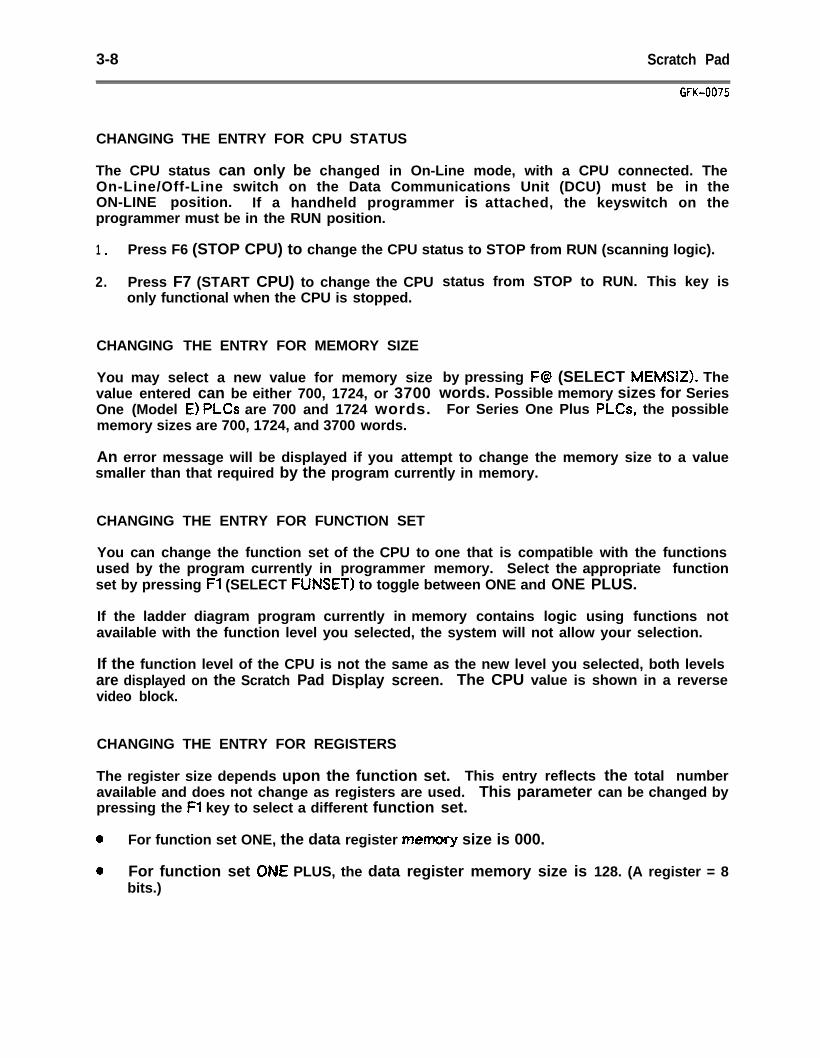
3-8 Scratch Pad
GFK-0075
CHANGING THE ENTRY FOR CPU STATUS
The CPU status can only be changed in On-Line mode, with a CPU connected. TheOn-Line/Off-Line switch on the Data Communications Unit (DCU) must be in theON-LINE position. If a handheld programmer is attached, the keyswitch on theprogrammer must be in the RUN position.
1 . Press F6 (STOP CPU) to change the CPU status to STOP from RUN (scanning logic).
2. Press F7 (START CPU) to change the CPUonly functional when the CPU is stopped.
CHANGING THE ENTRY FOR MEMORY SIZE
You may select a new value for memory sizevalue entered can be either 700, 1724, or 3700One (Model E) PLCs are 700 and 1724 words.memory sizes are 700, 1724, and 3700 words.
status from STOP to RUN. This key is
by pressing F@ (SELECT MEMSIZ). Thewords. Possible memory sizes for SeriesFor Series One Plus PLCs, the possible
An error message will be displayed if you attempt to change the memory size to a valuesmaller than that required by the program currently in memory.
CHANGING THE ENTRY FOR FUNCTION SET
You can change the function set of the CPU to one that is compatible with the functionsused by the program currently in programmer memory. Select the appropriate functionset by pressing Fl (SELECT FUNSET) to toggle between ONE and ONE PLUS.
If the ladder diagram program currently in memory contains logic using functions notavailable with the function level you selected, the system will not allow your selection.
If the function level of the CPU is not the same as the new level you selected, both levelsare displayed on the Scratch Pad Display screen. The CPU value is shown in a reversevideo block.
CHANGING THE ENTRY FOR REGISTERS
The register size depends upon the function set. This entry reflects the total numberavailable and does not change as registers are used. This parameter can be changed bypressing the Fl key to select a different function set.
a For function set ONE, the data register memory size is 000.
0 For function set OM PLUS, the data register memory size is 128. (A register = 8bits.)

Display Program 4-1
GFK-0075
CHAPTER 4DISPLAY PROGRAM
The Display Program function is used to display ladder logic, showing power flow throughthe rungs. If the program is annotated, names and nicknames can be shown in theprogram. Rung explanations and coil labels can be shown in Window or in full-screenPage mode.
Display Program includes full search capabilities, allowing you to quickly locate any rung,reference, nickname, or element in the program.
In addition, the Display Program function allows data values and constants to be changedwhen the system is on-line with an operating CPU.
This chapter explains how to use the features of Display Program. Refer to theappropriate sections:
.
Section 1. Displaying a Program: Section 1 explains how to display a program. Thissection also shows program display format, and summarizes the instructions forannotation display.
Section 2. Searching for a Program Element: Section 2 gives basic instructions forlocating an element of the program currently being displayed.
Section 3. Making On-Line Changes: Section 3 explains how to make data value andconstant changes to the program and the effect of on-line changes.
4-2 Display Program
GFK-0075
SECTION 1DISPLAYING A PROGRAM
This section explains:
0 How to display a program.
a Program display format.
0 Display Program function key assignments.
0 HOW to go from program display to the reference tables display.
l How to display a specified rung of the program.
0 How to scroll the ladder logic display.
a How to display annotation.
HOW TO DISPLAY A PROGRAM
To display a program, follow the steps below:
1 .
2 .
3 .
Display Program displays the program currently in programmer memory. If theprogram you want to display is the one now in programmer memory, go to step 5.
If the program is not currently in programmer memory, you can load it using theLoad/Store/Verify functions, or the quick-load feature from the Supervisor menu.For On-Line display, the program in the CPU and the program in p r o g r a m m e rmemory must be equal. If the program is loaded from the CPU, they are equal.Otherwise, the program in programmer memory must be stored to the CPU.
If you want to load a program from the CPU, or if you want to check the accuracy ofthe transferred program with the Verify function, go to step 4 for instructions onusing Load/Store/Verify. Otherwise, you can quickly load the program directly fromthe Supervisor menu.
A .
B .
C .
If the file name is not the active file name, type it in. A drive ID followed by acolon can be used before the program name if the program is not on the defaultdisk. Press the Enter key (CTRL-El.
When the file name is active, press the ALT and L keys simultaneously to loadthe file. The screen will display the following message after the program issuccessfully loaded:
LOAD COMPLETE
Go to step 5.
Display Program 4-3
GFK-0075
4 . If you want to load a program from the CPU, or use the Verify function, select Load/Store/Verify (F6) from the Supervisor menu.
A . In the Load/Store/Verify menu, press Fl (LOAD).
B . On the Load Program/Tables screen, enter the drive ID for the program file. This may be P for the CPU, or it may be the diskette or hard disk ID. After entering the drive ID, move the cursor to PROGRAM NAME. Enter the name of the program to be displayed. Press the Enter key (CTRL-E).
C . When the load is complete, you can use the Verify function to check program content. For more information, refer to chapter 9.
Return to the Supervisor menu through the L/S/V menu, or by pressing the Supervisor key.
5 . In the Supervisor menu, type in the name of the program to be displayed. Then, select Display Program (F1).
NOTE
If there is no name in the text area, the last program name used in either Display Program or Edit Program is used. If no program name is either entered or retained from the Display or Edit Program functions, the system displays the last program that was used. You can delete this name by typing in NONE.
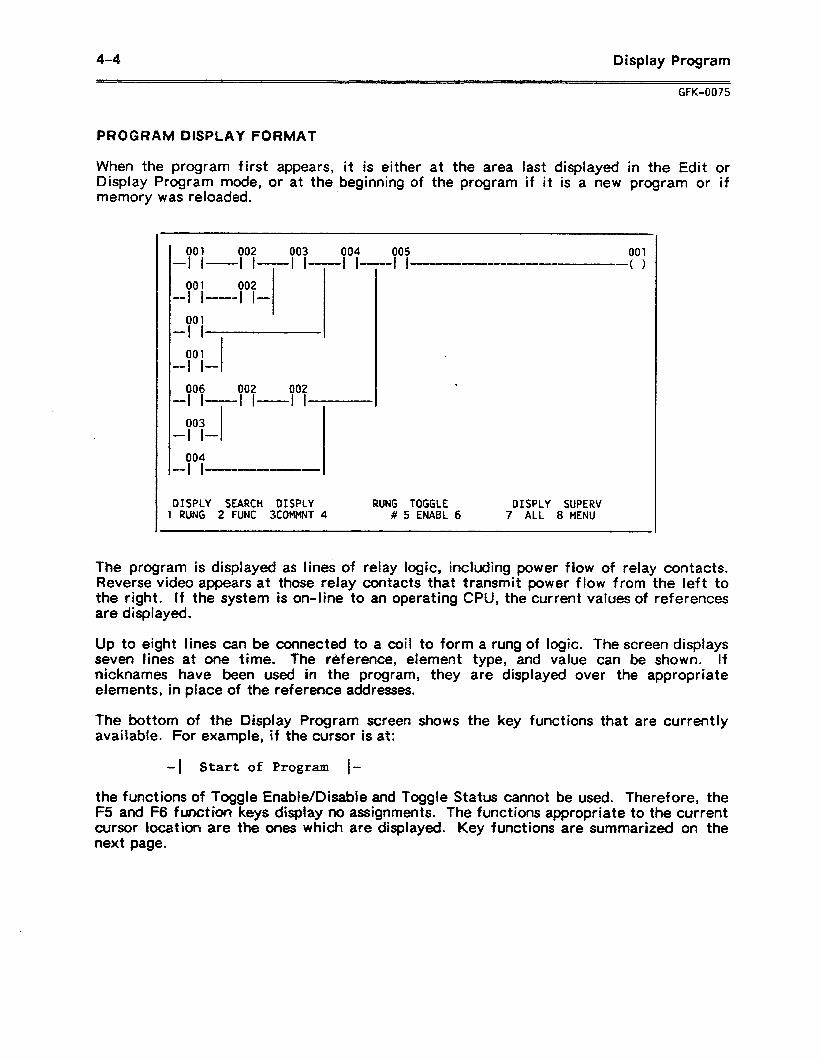
4-4 Display Program
WK-0075
PROGRAM DISPLAY FORMAT
When the program first appears, it is either at the area last displayed in the Edit or Display Program mode, or at the beginning of the program if it is a new program or if memory was reloaded.
001 002 003 004 005
-I 001
I II II II -II II ---II-- --- (1
001 002 -I I-- l l-
001 -I I
001 -I I-
006 002 002
.
-I I-I I ----_ I I 003
-I I- 004
-I I--
DISPCY SEARCH DISPLY RUNG TOGGLE DISPLY SUPERV 1 RUNG 2 FUNC 3COMMNT 4 # 5 ENABL 6 7 ALL 8 MENU
The program is displayed as lines of relay logic, including power flow of relay contacts. Reverse video appears at those relay contacts that transmit power flow from the left to the right. If the system is on-line to an operating CPU, the current values of references are displayed.
Up to eight lines can be connected to a coil to form a rung of logic. The screen displays seven lines at one time. The reference, element type, and value can be shown. If nicknames have been used in the program, they are displayed over the appropriate elements, in place of the reference addresses.
The bottom of the Display Program screen shows the key functions that are currently available. For example, if the cursor is at:
-1 Start of Program I-
the functions of Toggle Enable/Disable and Toggle Status cannot be used. Therefore, the F5 and F6 function keys display no assignments. The functions appropriate to the current cursor location are the ones which ate displayed. Key functions are summarized on the next page.
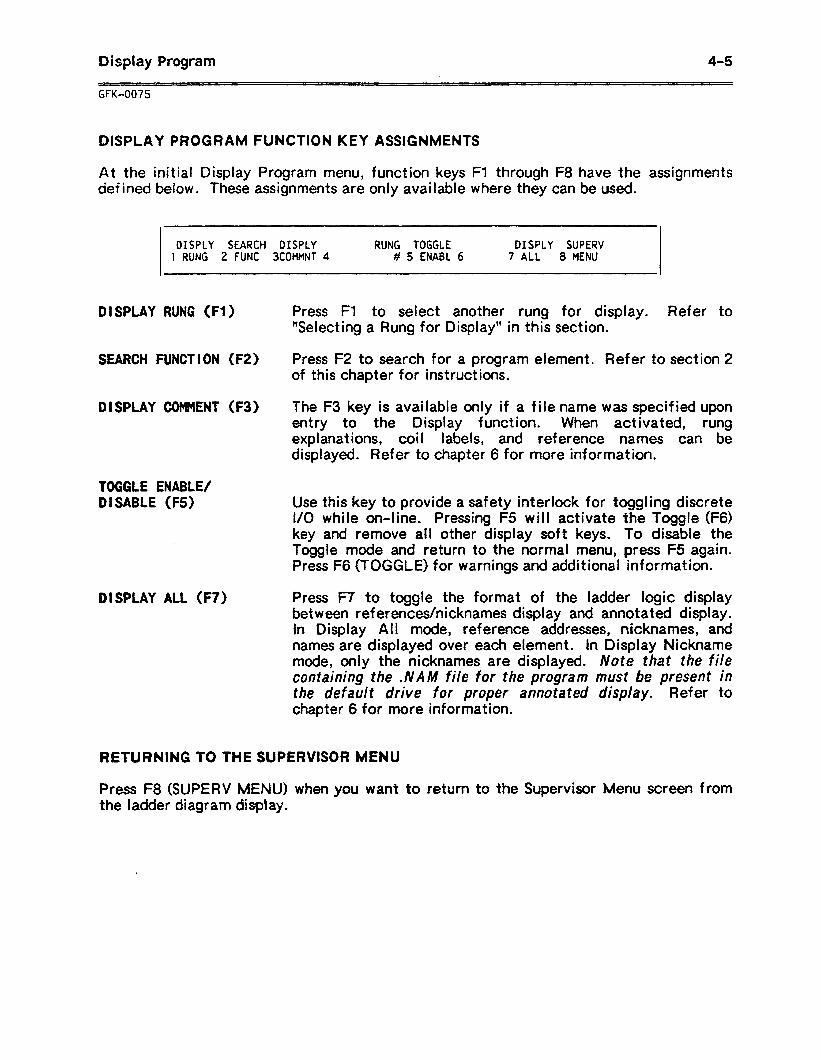
Display Program 4-5
GFK-0075
DISPLAY PROGRAM FUNCTION KEY ASSIGNMENTS
At the initial Display Program menu, function keys Fl through F8 have the assignments defined below. These assignments are only available where they can be used.
DISPLY SEARCH DISPLY RUNG TOGGLE DISPLY SUPERV 1 RUNG 2 FUNC 3COMMNT 4 # 5 ENABC 6 7 ALL 8 MENU
D I SPLAY RUNG (Fi)
SEARCH FUNCT I ON (F2)
01 SPLAY COMMENT (F3)
TOGGLE ENABLE/ DISABLE (F5)
DISPLAY ALL (F7)
Press Fl to select another rung for display. Refer to “Selecting a Rung for Display” in this section.
Press F2 to search for a program element. Refer to section 2 of this chapter for instructions.
The F3 key is available only if a file name was specified upon entry to the Display function. When activated, rung explanations, coil labels, and reference names can be displayed. Refer to chapter 6 for more information.
Use this key to provide a safety interlock for toggling discrete I/O while on-line. Pressing F5 will activate the Toggle (F6) key and remove all other display soft keys. To disable the Toggle mode and return to the normal menu, press F5 again. Press F6 (TOGGLE) for warnings and additional information.
Press F7 to toggle the format of the ladder logic display between references/nicknames display and annotated display. In Display All mode, reference addresses, nicknames, and names are displayed over each element. In Display Nickname mode, only the nicknames are displayed. Note that the file containing the .NAM file for the program must be present in the default drive for proper annotated display. Refer to chapter 6 for more information.
RETURNING TO THE SUPERVISOR MENU
Press F8 (SUPERV MENU) when you want to return to the Supervisor Menu screen from the ladder diagram display.
4-6 Display Program
GFK-0075
GOING TO THE REFERENCE TABLES DISPLAY
To display the reference tables:
f . Press the Supervisor key to access the Supervisor menu.
2 . Then, select Display Reference Tables by pressing F3. The last table displayed reappears.
SELECTING A RUNG FOR DISPLAY
To display another rung at the top of the screen:
1 . Enter one of the following parameters:
A . A rung number: Enter an unsigned decimal value in the numeric line of the screen’s work area.
B . A memory address: Enter a constant (K) decimal value in the reference line of the screen’s work area.
,
C . A coi I reference: Enter an appropriate output value in the reference address field of the work area.
2. Press Fl (DISPLY RUNG). The rung will be displayed at the top of the screen.
The cursor will be positioned at either the first element, memory address, or coil, depending on which was selected in step 1.
MOVING THE CURSOR
Use the cursor keys to move the cursor on the ladder diagram.
MOVING THE DISPLAY UP OR DOWN
The cursor can be moved up or down one line at a time, one rung at a time, or seven lines at a time.
1 . Use the Up and Down cursor keys to scroll the screen up or down one line at a time.
A . Scroll the display upward by pressing the bwn cursor key with the cursor at the bottom of the screen.
B . Scroll the display downward by pressing the Up cursor key with the cursor at the top of the screen.
2. Press CTRL-N (NEXT or Return) to display the next rung (up to seven lines) of the program. Press Shift-NEXT at the same time to display the next seven lines of the program.
3 . Press CTRL-P (PREV) to display the previous rung (up to seven lines) of the program. Press Shift-PREV at the same time to display the previous seven lines of the program.
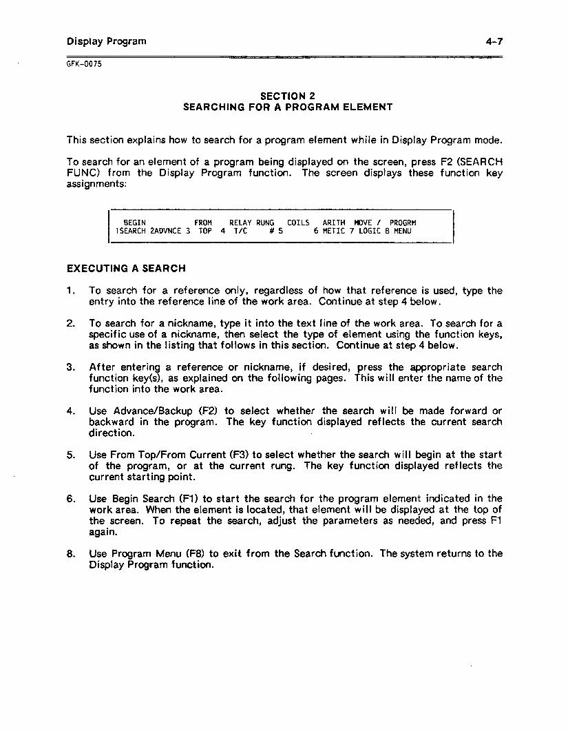
Display Program
GFK-0075
4-7
SECTION 2 SEARCHING FOR A PROGRAM ELEMENT
This section explains how to search for a program element while in Display Program mode.
To search for an element of a program being displayed on the screen, press F2 (SEARCH FUNC) from the Display Program function. The screen displays these function key assignments:
BEGIN FROM RELAY RUNG COILS ARITH MOVE / PROGRM SEARCH ZADVNCE 3 TOP 4 T/C # 5 6 METIC 7 LOGIC 8 MENU
EXECUTING A SEARCH
1 .
2 .
3 .
4 .
5 .
6 .
8 .
To search for a reference only, regardless of how that reference is used, type the entry into the reference line of the work area. Continue at step 4 below.
To search for a nickname, type it into the text line of the work area. To search for a specific use of a nickname, then select the type of element using the function keys, as shown in the listing that follows in this section. Continue at step 4 below.
After entering a reference or nickname, if desired, press the appropriate search function key(s), as explained on the following pages. This will enter the name of the function into the work area.
Use Advance/Backup (F2) to select whether the search will be made forward or backward in the program. The key function displayed reflects the current search direct ion.
Use From Top/From Current (F3) to select whether the search will begin at the start of the program, or at the current rung. The key function displayed reflects the current starting point.
Use Begin Search (Fl) to start the search for the program element indicated in the work area. When the element is located, that element will be displayed at the top of the screen. To repeat the search, adjust the parameters as needed, and press Fl again.
Use Program Menu (F8) to exit from the Search function. The system returns to the Display Program function.
4-8 Display Program
GFK-0075
“Wildcat-d” Nickname Search
An asterisk (*I can be used to search the nickname. For example, entering
1 . Enter the nickname in the work at the end.
I for similar nicknames. It must be used at the end of PB* would search for PBl, PB2, or PB3.
area, using the * to replace the variable characters
2 . Use From Top/From Current (F3) to select the starting point.
3 . Use Advance/Backup (F2) to select the direction of the search.
4 . Use Begin Search (Fl) to start the search.
SEARCH KEYS: DEFINITIONS
The Search Function keys are summarized below:
BEGIN SEARCH (Fl ) Use Fl to start the search for the element defined in the work area. Selections relating to the search operation must be made prior to pressing this key.
ADVANCE/BACKUP (F2) F2 toggles the search direction between forward and reverse.
FROM TOP/ FROM CURRENT (F3) F3 toggles the starting point for the search between the top
of the program and the current cursor location.
Each of the following four function keys activates a menu of instructions. Selecting one of the instruction keys within each menu will place the instruction in the work area and specify a search for that instruction. The instructions accessed from each menu are listed below:
RELAYS 1 TIMERS/COUNTERS (F4) Use F4 to access Relays, Drum Sequencers, Timers, and
Counters.
COILS (F5) Use F5 to access Out, Set, Reset, Set Out, and Set Out Reset Coils, Shift Registers, and High Speed Counters.
ARITHMETIC INSTRUCTIONS (F6) Use F6 to access Addition, Subtraction, Multiplication,
Division, Compare, BCD to Binary, and Binary to BCD instruct ions.
DATA MOVE, LOGIC, and SPEC I AL INSTRUCTIONS (F7) Use F7 to access DSTRO, DSTRl, DSTRZ, DOUTO, DOUTl,
DOUT2, DAND, DOR, Invert, Shift Right, Shift Left, DSTR3, MCS, MCJ?, External Fault Diagnosis, Decode, Encode, DSTR5, DOUTS, and Bad Opcode instructions.
Display Program 4-9
RETURNING TO THE DISPLAY FUNCTION MENU
Press F8 (PROGRM MENU) to return to the Display Program menu.
SEARCHING FOR THE CAUSE OF A DOUBLE LEFT RAIL
A double left rail in the ladder logic means a Master Control Relay (MCI?) is controlling execution of the rungs. To locate the cause of a double left rail, search backward f ram the current rung. Search for an MSC to find the beginning of controlled logic and an MCR to find the end. Do not include references.
4-10 Display Program
GFK-0075
SECTION 3 MAKING ON-LINE CHANGES IN THE PROGRAM
Data values and program constant (K) changes can be made to the program in Display Program mode. This section explains:
0 The effect of on-line changes in the program.
0 Under what conditions on-line changes may be made.
0 How to change a constant.
EFFECT OF ON-LINE CHANGES
The effect of on-line changes made in Display Program mode depends upon the current mode (On-Line, Off-Line, or Monitor), whether the program in the CPU is equal or not equal to the program in programmer memory, and whether on-line changes are enabled.
When the system is in On-Line or Monitor mode, status information can be obtained from a connected CPU. This information includes l/O state and register content. To ensure an accurate display, the Logicmaster 1F system requires that the CPU and system programs are equal. If they are not equal, or the CPU is locked, data will not be displayed and on-line changes are not permitted.
When the system is connected to a scanning CPU, with the program in memory equal to the program in the CPU, in the On-Line or Monitor mode, power flow to the rungs of the ladder diagram is shown in reverse video. As the CPU status changes, displays are updated. Note that if rungs are added or deleted while in the Editor mode, the program in memory and the CPU become “Not Equal”.
When the system is in the On-Line mode and the CPU is unlocked, on-line changes are permitted. The values of data registers 400477 and timer/counter accumulate registers 600-677 can be changed when the CPU is in either run or stopped mode. Discrete I/O and references 000457 and 700-767 can be changed only when the CPU is in run mode.
On-line changes to preset constants are permitted when the CPU is in either run or stop mode. On-line changes to all other constants are only permitted when the CPU is stopped.
When the system is in Off--Line mode, the status is always obtained from programmer memory. In the Off-Line mode, power flow is shown with numerical values from programmer memor)f. Registers 400-677 can be changed off-line, although new values are not transferred to the CPU. Discrete I/O and registers O-77 cannot be changed off-line.
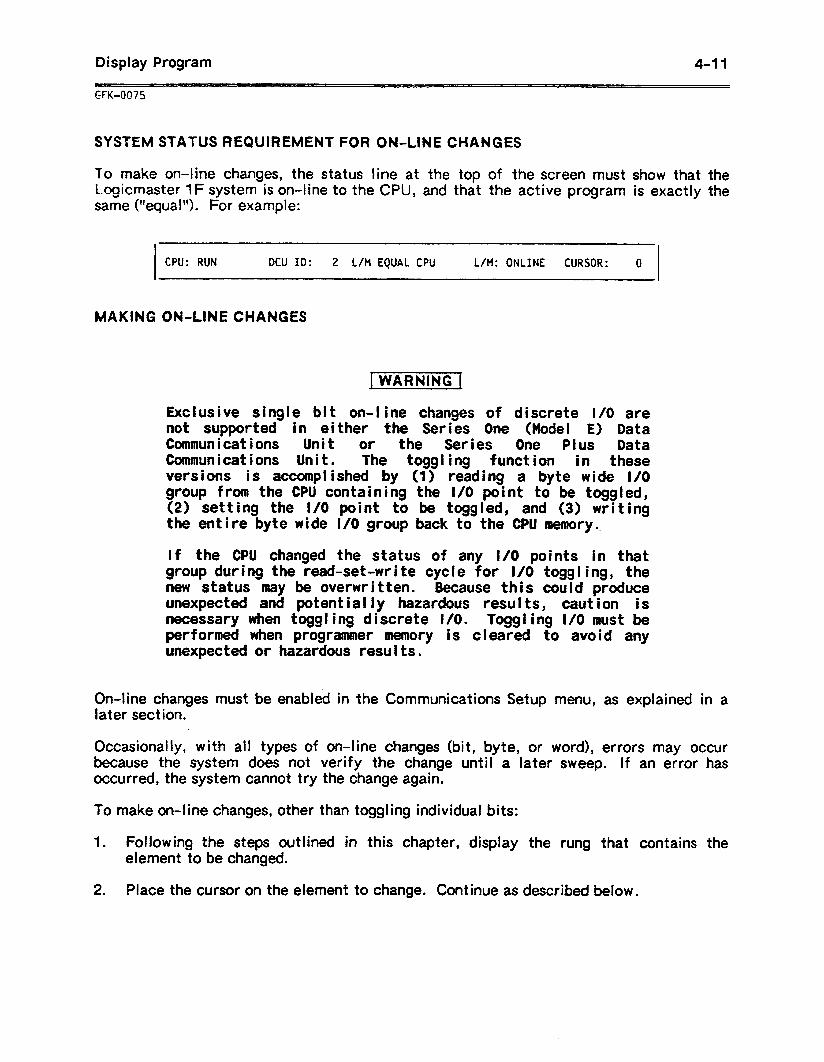
Display Program 4-l 1
GFK-0075
SYSTEM STATUS REQUIREMENT FOR ON-LINE CHANGES
To make on-line changes, the status line at the top of the screen must show that the Logicmaster 1F system is on-line to the CPU, and that the active program is exactly the same (“equal”). For example:
CPU: RUN DCU ID: 2 L/M EQUAL CPU L/M: ONLINE CURSOR: 0
MAKING ON-LINE CHANGES
Exclusive single bit on-line changes of discrete l/O are not supported in either the Series One (Model E) Data Communications Unit of the Series One Plus Data Communications Unit. The toggling function in these versions is accomplished by (1) reading a byte wide I/O group from the CPU containing the I/O point to be toggled, (2) setting the I/O point to be toggled, and (3) writing the entire byte wide I/O group back to the CPU memory..
If the CPU changed the status of any I/O points in that group during the read-set-write cycle for I/O toggling, the new status may be overwritten. Because this could produce unexpected and potentially hazardous results, caution is necessary when toggling discrete I/O. Toggling l/O must be performed when programmer memory is cleared to avoid any unexpected or hazardous results.
On-line changes must be enabled in the Communications Setup menu, as explained in a later sect ion.
Occasionally, with all types of on-line changes (bit, byte, or word), errors may occur because~ the system does not verify the change until a later sweep. If an error has occurred, the system cannot try the change again.
To make on-line changes, other than toggling individual bits:
1 . Following the steps outlined in this chapter, display the rung that contains the element to be changed.
2 . Place the cursor on the element to change. Continue as described below.
4-l 2 Display Program
UK-0075
Changing a Constant
To change a constant, type the new constant into the work area and press the Enter key (CTRL-E).
Changing the Content of a Numeric Field
To change the content of a register, or 8 or 16 bits of I
1 . Place the cursor on the item to be changed.
2 . Type the new value into the work area. Press the
10 . .
Enter key.
Edit Program 5-l
GFK-0075
CHAPTER 5 EDIT PROGRAM
The Edit Program function, which is available in all modes, is used to create or modify a ladder logic program in programmer memory.
If the Edit function is entered with an active file name, annotation can be edited. In addition, disk memory will be updated whenever a rung is accepted. A file name is activated from the Supervisor menu, by entering a valid file name and pressing CTRL-E or the Enter key, or the Edit Program function key.
If a file name is not active, the program must be stored to disk using the L/S/V functions. That means if power goes off while editing, changes will be lost.
Like Display Program, the Edit Program function contains full search capabilities. You can quickly locate any rung, reference, nickname, or other element in a program.
This chapter explains how to use the Logicmaster 1 Family Software package to enter or modify a ladder logic program. Refer to the following sections:
Section 1 l Entering Edit Pfogramn_mM@e: Section 1 explains how to begin the Edit Program function.
Section 2. Editing the Program: For instructions on editing a program, refer to section 2.
Section 3. Editing a Rung: Section 3 explains how to create or edit a rung.
Section 4. Searching for a Program Element: Section 4 explains how to search for a particular element of a program, such as a reference or a program instruction.
Section 5. Ladder Diagram File Editing: Section 5 explains how to copy part of a program into another file. It also explains how to merge program files.
5-2 Edit Program
GFK-0075
SECTION 1 ENTERING EDIT PROGRAM MODE
This sect ion explains:
0 How to start a new program. 0 How to display an existing program for editing. l How to create a backup program, if you are editing an existing program.
STARTING A NEW PROGRAM
To start a new program, follow these steps:
1 . Edit Program edits the program in programmer memory. if there is another program already in memory, you must either store it or clear memory using the Load/Store/Verify functions. If necessary, refer to chapter 8 for instructions.
2. When memory is clear, you can begin the new program. In the work area, type either:
A l The program name, if you want to automatically update the program on disk after each rung is accepted. This is recommended. Entering the program name is also necessary for annotation.
The name can have up to 8 characters. it should be different from any other program name on the disk. Uppercase and lowercase characters are displayed, but are considered to be the same by the system. Do not use the following reserved words as program names: NONE, CON, PRN, AUX, COMl, COM2, LPTl, LPT2, LPT3, NUL.
Press CTRL-E or the Enter key to enter the name.
B . If you do not want to enter a name, type the word NONE. To save the program later, you will have to store it to disk using the Load/Store/Verify functions.
3 . Select Edit Program by pressing F2. The beginning of a new program appears. Now go to section 2, EDITING THE PROGRAM.
Edit Program 5-3
GFK-0G7S
DISPLAYING AN EXISTING PROGRAM FOR EDITING
1 .
2 .
3 .
. 4 .
Edit Program edits the program currently in programmer memory. If the program you want to edit is the one now in memory, go to step 5.
If the program is not currently in programmer memory, you can load it using the Load/Store/Verify functions, or the quick-load feature from the Supervisor menu.
If you want to load a program from the CPU, or if you want to check the accuracy of the transferred program with the Verify function, go to step 4 for instructions on using the Load/Store/Verify function. Otherwise, you can quickly load the program directly from the Supervisor menu.
A . If the file name is not the active file name, type it in and press CTRL-E or the Enter key.
B . When the file name is active, press the A’LT-L keys to load the file.
C . Go to step 5.
If you want to load a program from the CPU, or use the Verify function, select Load/Store/Verify (F6) f ram the Supervisor menu.
A .
B .
c .
D .
In the Load/Store/Verify menu, press Fl (LOAD).
On the Load Program/Tables screen, enter the drive ID for the program file. This may be P for the CPU, or it may be the diskette or hard disk ID. After entering the drive ID, move the cursor to PROGRAM NAME. Enter the name of the program to be displayed, and press CTRL-E or the Enter key.
When the load is complete, you can use the Verify function to check program content. For more information, refer to chapter 9.
Return to the Supervisor menu through the L/S/V menu, or by pressing the Supervisor key.
In the Supervisor menu, type in either:
0 The program name, if you want to automatically save the program to disk after each rung is accepted. This is recommended. entering the program name is also necessary for annotation.
0 If you do not want to enter a name, type the word NONE. To save the program later, you will have to store it to disk using the Load/Store/Verify functions.
5-4 Edit Program
GFK-0075
5. Select Edit Program (FZ). If a program with the name entered is located on the disk, the system checks the contents of its programmer memory against the contents of the disk. Any differences are noted. However, the programmer memory is not loaded from the disk at this time.
If no program is found with the name that you entered, no comparison is performed. A new editable copy of the program is stored to the active disk under the specified file name.
If you load an existing program but give it a new name in the work area, an editable copy of the program will be stored to disk under the new name. The new name must not be the same as the name of any other program on the disk.
CREATING A BACKUP PROGRAM
If there is a program already in memory with the same name when you enter Edit Program mode, the screen prompts:
DO YOU WISH TO BACKUP PROGRAM? (Y/N)
A backup program is a copy of the program before any new editing changes are made. Only one backup version of a program is permitted. A new backup destroys any old backup versions of the same program.
To make a backup program, type Y. A disk. The existing .LAD, .NAM, .RDF, of .LBU, .NBU, .RBU, and .EBU. If you
In addition to making a backup copy of backup diskettes. _
ABORTING AN EDIT SESSION
copy of the current version will be stored on the and .EXP files will be duplicated with extensions do not want to back up the program, type N.
the file on disk, you should also keep a library of
Any edit session may be aborted by pressing F9 or the Abort key. If any text was changed during the edit session, you must confirm the abort by pressing ALT-X (Confirm or Shift-O). By confirming the abort, no text is stored to disk and the text will be redisplayed as it appeared before you began the edit session.
If the F9 or Abort key was accidentally pressed, pressing any key other than ALT-X (Confirm or Shift-O) will continue the edit session.
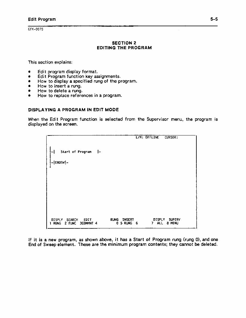
Edit Program 5-5
SECTION 2 EDITING THE PROGRAM
This sect ion explains:
0 Edit program display format. 0 Edit Program function key assignments. 0 How to display a specified rung of the program. 0 How to insert a rung. * How to delete a rung. 0 How to replace references in a program.
DISPLAYING A PROGRAM IN EDIT MODE
When the Edit Program function is selected from the Supervisor menu, the program is displayed on the screen.
-1 Start of Program I-
L/M: OFFLINE CURSOR:
DISPLY SEARCH EDIT RUNG INSERT DISPLY SUPERV 1 RUNG 2 FUNC 3COMMNT 4 0 5 RUNG 6 7 ALL 8 MENU
If it is a new program, as shown above, it has a Start of Program rung (rung O), and one End of Sweep element. These are the minimum program contents; they cannot be deleted.
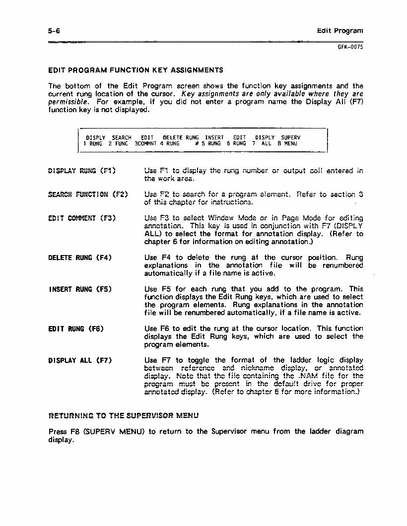
5-6 Edit Program
GFK-0075
EDIT PROGRAM FUNCTION KEY ASSIGNMENTS
The bottom of the Edit Program screen shows the function key assignments and the current rung location of the cursor. Key assignments are only available where they are permissible. For example, if you did not enter a program name the Display Ail (F7) function key is not displayed.
DISPLY SEARCH EDIT DELETE RUNG INSERT EDIT DISPLY SUPERV 1 RUNG 2 FUNC 3COMMNT 4 RUNG # 5 RUNG 6 RUNG 7 ALL 8 MENU
D I SPLAY RUNG (Fl) Use Fl to display the rung number or output coil entered in the work area.
SEARCH FUNCTION (F2) Use FZ to search for a program element. Refer to section 3 of this chapter for instructions. .
EDIT COMMENT (F3) Use F3 to select Window Mode or in Page Mode for editing annotation. This key is used in conjunction with F7 (DISPLY ALL) to select the format for annotation display. (Refer to chapter 6 for information on editing annotation.)
DELETE RUNG (F4)
INSERT RUNG (F5)
EDIT RUNG (F6)
DISPLAY ALL (F7)
Use F4 to delete the rung at the cursor position. Rung explanations in the annotation file will be renumbered automatically if a file name is active.
Use F5 for each rung that you add to the program. This function displays the Edit Rung keys, which are used to select the program elements. Rung explanations in the annotation file will be renumbered automatically, if a file name is active.
Use F6 to edit the rung at the cursor location. This function displays the Edit Rung keys, which tire used to select the program elements.
Use F7 to toggle the format of the ladder logic display between reference and nickname display, or annotated display. Note that the file containing the .NAM file for the program must be present in the default drive for proper annotated display. (Refer to chapter 6 for more information.)
RETURNING TO THE SUPERVISOR MENU
Press F8 (SUPERV MENU) to return to the Supervisor menu from the ladder diagram display.
Edit Brogram 5-7
GFK4@?5
DISPLAYING A SPECIFIED RUNG
1 .
2 .
Type one of the following into the work area:
A . Enter the number of the rung in the data line, in decimal format. B . Enter a coil reference in the reference line. C . Enter the memory address in the reference line, as a decimal constant (K). D . Enter the nickname in the text line.
Press Fl (DISPLY RUNG). The selected rung is displayed at the top of the screen, followed by up to six lines of the program. The cursor indicates the rung, coil, or memory address that was specified.
INSERTING A RUNG
1 . If the new location for the rung is not shown, display it using the Search or Display Rung function.
2 . Place the cursor on an element in the rung BEFORE the location where you want the new rung.
3 . Press F5 (INSERT RUNG).
EDITING A RUNG
1 . If the rung is not shown, display it using the Search or Display Rung function.
2 . Place the cursor on the rung to be edited.
3 . Press F6 (EDIT RUNG).
4 . Continue at section 3, EDITING A RUNG.
DELETING ONE OR MORE PROGRAM RUNGS
1 . Decide how many rungs will be deleted.
2 . Place the cursor on the first rung to be deleted. If the rung is not shown on the screen, display it using the Search or Display Rung function.
3 . If you are deleting just one rung, press F4 (DELETE RUNG). Go immediately to step 5. The following message will be displayed:
PRESS ALT-X (confirm) TO DELETE RUNG x
4 . If you are deleting multiple rungs, use the Select key to move the cursor to the data line (bottom line) of the work area. Then type in the number of rungs to be deleted. Press ALT-D to delete the rungs. The following message will be displayed:
PRESS ALT-X (confirm) TO DELETE RUNG x - x
5-8 Edit Program
GFK-0075
5. TO confirm the deletion, press ALT-X (Conf km or Shift-O). To cancel the deletion, press any other key.
6 . Repeat this procedure for the next rung to be deleted.
REFERENCE SUBSTITUTION IN A PROGRAM
The Reference Substitition function allows you to globally replace all occurrences of a reference within a program. This allows you to randomly select references during program development. After the real hardware points are established, the Reference Substitution function can replace these randomly-selected points with correct reference addresses. The reference can be replaced in two ways; both are described below.
if the program is not currently in memory, load it in, as previously described. The program name must be the active file name. If the file name is not currently active, the following error message wil I be displayed:
FUNCTION ONLY VALID WITH FILE NAME ACTIVE
-Replacing the Same Reference Type in a Program
Follow the steps below to replace a reference:
1 . With the Edit Program main menu keys displayed, enter the new reference address into the reference (center) line of the work area.
2 . Enter the old reference into the data (bottom) line of the work area by pressing the Octal key (Shift/C), to change the base to OCTAL. Enter only the reference number, not the reference type. The following entries 102:
would replace the reference 100 with
Text Line Reference Line Data Line I
102 190
(no entry) NEW Reference OLD Reference
3. Press ALT-S to begin the replacement. The following mesage will be displayed:
PRESS ALT-X (confIrm) TO REPLACE ALL OCCURRENCES OF BY
4 . Press ALT-X (Confirm or Shift-O) to confirm the global substitution.
5 . If during the global substitution, the new reference cannot replace the old reference, the screen will display the rung where the substitution was unsuccessful and you will be allowed to abort or continue. If you choose to abort the substitution at any time during the process, the .LAD file will be automatically reloaded from disk to restore it to its previous state before this last global substitution.
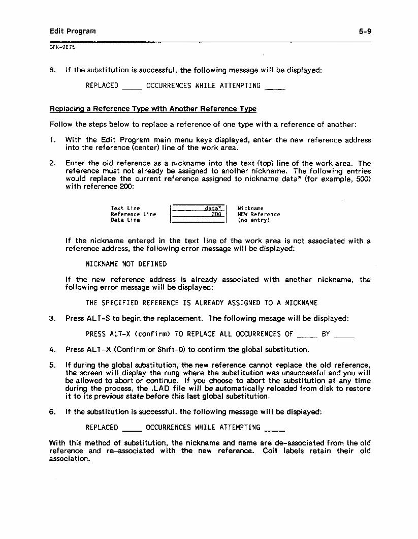
Edit Program 5-9
6 . If the substitution is successful, the following message w i I I be displayed:
REPLACED OCCURRENCES WHILE ATTEMPTING
Replacing a Reference Type with Another Reference Type
Follow the steps below to replace a reference of one type with a reference of another:
1 . With the Edit Program main menu keys displayed, enter the new reference address into the reference (center) line of the work area.
2. Enter the old reference as a nickname into the text (top) line of the work area. The reference must not already be assigned to another nickname. The following entries would replace the current reference assigned to nickname data* (for example, 500) with reference 200:
-
Text Line data Reference Line
I 1
Data Line
Nickname
.
NEW Reference (no entry)
If the nickname entered in the text line of the work area is not associated with a reference address, the following error message will be displayed:
NICKNAME NOT DEFINED
If the new reference address is already associated with another nickname, the f ol lowing error message will be displayed:
THE SPECIFIED REFERENCE IS ALREADY ASSIGNED TO A NICKNAME
3 . Press ALT-S to begin the replacement. The following mesage will be displayed:
PRESS ALT-X (confirm) TO REPLACE ALL OCCURRENCES OF BY
4 . Press ALT-X (Confirm or Shift-O) to confirm the global substitution.
5 . If during the global substitution, the new reference cannot replace the old reference, the screen will display the rung where the substitution was unsuccessful and you will be allowed to abort or continue. If you choose to abort the substitution at any time during the process, the .LAD file will be automatically reloaded from disk to restore it to its previous state before this last global substitution.
6 . If the substitution is successful, the following message will be displayed:
REPLACED OCCURRENCES WHILE ATTEMPTING
With this method of substitution, the nickname and name are de-associated f ram the old reference and re-associated with the new reference. Coil labels retain their old association.
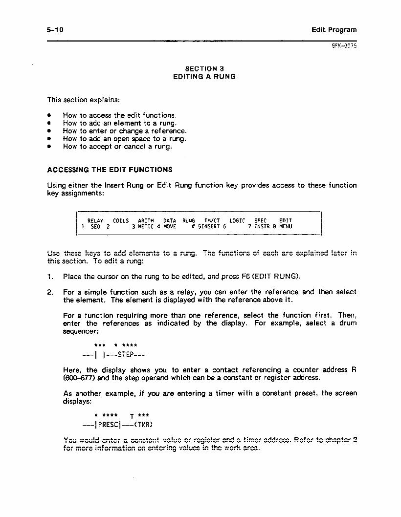
5-l 0 Edit Program
explains: This section I
a How to a How to 0 How to l How to 0 How to
ACCESSING THE EDIT FUNCTIONS
access the edit functions. add an element to a rung. enter or change a reference. add an open space to a rung. accept or cancel a rung.
GFK-0075
SECTION 3 EDITING A RUNG
Using either the Insert Rung or Edit Rung function key provides access to these function key assignments:
RELAY COILS ARITH DATA RUNG TM/CT LOGIC SPEC EDIT 1 SEQ 2 3 METIC 4 MOVE # SINSERT 6 7 INSTR 8 MENU
Use these keys to add elements to a rung. The functions of each are explained later in this section. To edit a rung:
1 . Place the cursor on the rung to be edited, and press F6 (EDIT RUNG).
2 . For a simple function such as a relay, you can enter the reference and then select the element. The element is displayed with the reference above it.
For a function requiring more than one reference, select the function first. Then, enter the references as indicated by the display. For example, select a drum sequencer:
*++ * ****
w-- 1 1 ---STEP---
Here, the display shows you to enter a contact referencing a counter address R (600-677) and the step operand which can be a constant or register address.
As another example, if you are entering a timer with a constant preset, the screen displays:
* **** T f+f
--- 1 PRESC 1 ---(TMR>
You would enter a constant value or register a& a timer address. Refer to chapter 2 for more information on entering values in the work area.
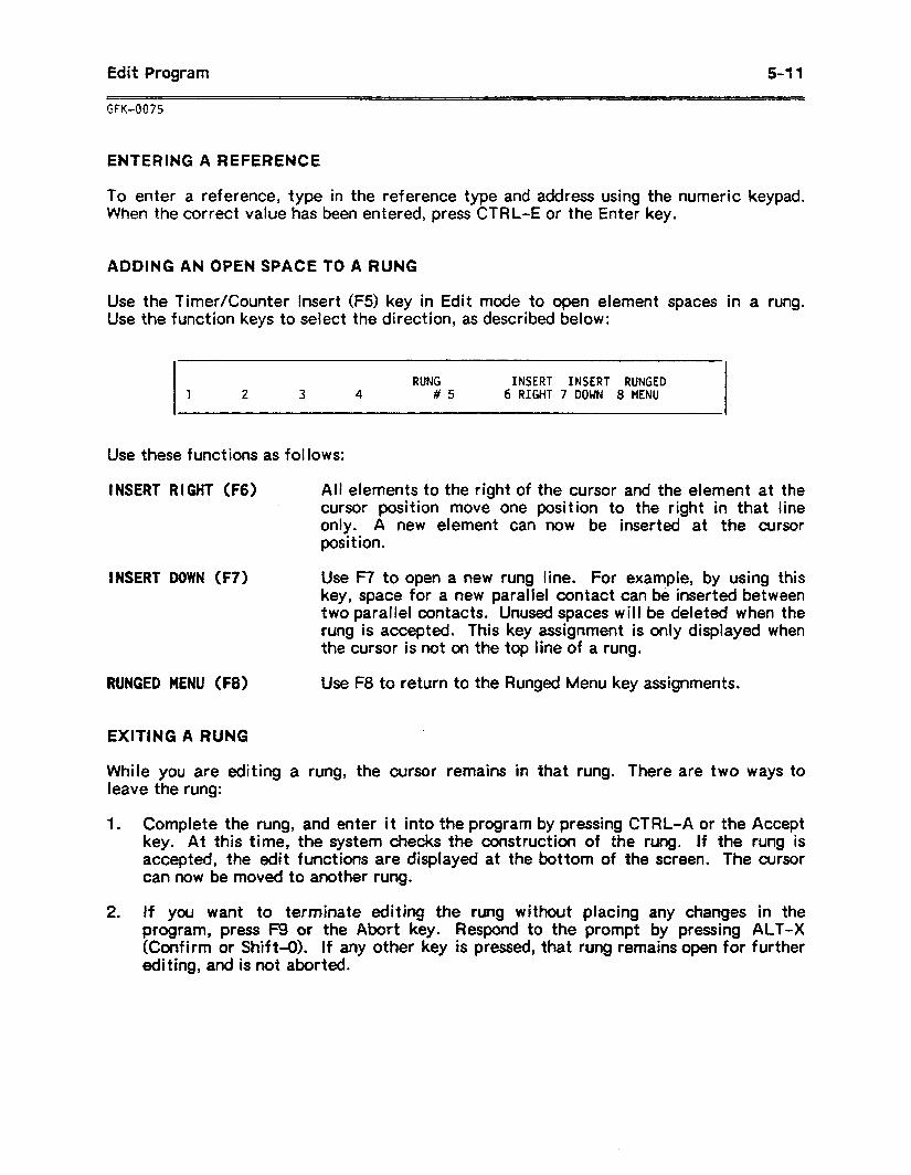
Edit Program 5-11
ENTERING A REFERENCE
To enter a reference, type in the reference type and address using the numeric keypad. B/hen the correct value has been entered, press CTRL-E or the Enter key.
ADDING AN OPEN SPACE TO A RUNG
Use the Timer/Counter Insert (FS) key in Edit mode to open element spaces Use the function keys to select the direction, as described below:
RUNG INSERT INSERT RUNGED 1 2 3 4 #5 6 RIGHT 7 DOWN 8 MENU
Use these functions as follows:
in a rung.
INSERT RIGHT (F6) Ail elements to the right of the cursor and the element at the cursor position move one position to the right in that line only. A new element can now be inserted at the cursor position.
INSERT DOWN (F7) Use F7 to open a new rung line. For example, by using this key, space for a new parallel contact can be inserted between two parallel contacts. Unused spaces will be deleted when the rung is accepted. This key assignment is only displayed when the cursor is not on the top line of a rung.
RUNGED MENU (F8) Use F8 to return to the Runged Menu key assignments.
EXITING A RUNG
While you are editing a rung, the cursor remains in that rung. There are two ways to leave the rung:
1 . Complete the rung, and enter it into the program by pressing CTRL-A or the Accept key. At this time, the system checks the construction of the rung. If the rung is accepted, the edit functions are displayed at the bottom of the screen. The cursor can now be moved to another rung.
2 . If you want to terminate editing the rung without placing any changes in the program, press F9 or the Abort key. Respond to the prompt by pressing ALT-X (Confirm or Shift-O). If any other key is pressed, that rung remains open for further editing, and is not aborted.
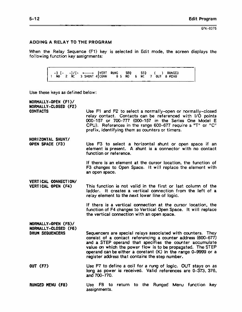
5-12 Edit Program
GFK-0075
ADDING A RELAY TO THE PROGRAM
When the Relay Sequence (Fl) key is selected in Edit mode, the screen displays the following function key assignments:
1 -NO
c- l/E - VERT RUNG SEQ SEQ ( ) RUNGED 1 2 -NC 3’SHUNf 4 I CONN 05 NO 6 NC 7 OUT 8 MENU
Use these keys as defined below:
NORMALLY-OPEN (Fl )/ NORMALLY-CLOSED (F2) CONTACTS
HORIZONTAL SHUNT/ OPEN SPACE (F3)
VERT VERT
Use Fl and FZ to select a normally-open or normally-closed relay contact. Contacts can be referenced with I/O points 000457 or 700-777 (000457 in the Series One Model E CPU). References in the range 600-677 require a “T’+ or W prefix, identifying them as counters or timers.
Use F3 to select a horizontal shunt or open space if an element is present. A shunt is a connector with no contact function or reference.
If there is an element at the curso F3 changes to Open Space. It w il an open space.
location, the function of replace the element with
ICAL CONNECTION/ ICAL OPEN (F4) This function is not valid in the first or last column of the
ladder. It creates a vertical connection from the ief t of a relay element to the next lower line of logic.
If there is a vertical connection at the cursor location, the function of F4 changes to Vertical Open Space. It will replace the vertical connection with an open space.
NORMALLY-OPEN (F5)/ NORMALLY-CLOSED (F6) DRUM SEQUENCERS Sequencers are special relays associated with counters. They
consist of a contact referencing a counter address (600-677) and a STEP operand that specifies the counter accumulate value on which the power flow is to be propagated. The STEP operand can be either a constant (K) in the range O-9999 or a register address that contains the step number.
OUT (F7)
RUNGED MENU (F8)
Use F7 to define a coil for a rung of logic. OUT stays on as long as power is received. Valid references are O-373, 376, and 700-770.
Use F8 to return to the Runged Menu function key assignments.
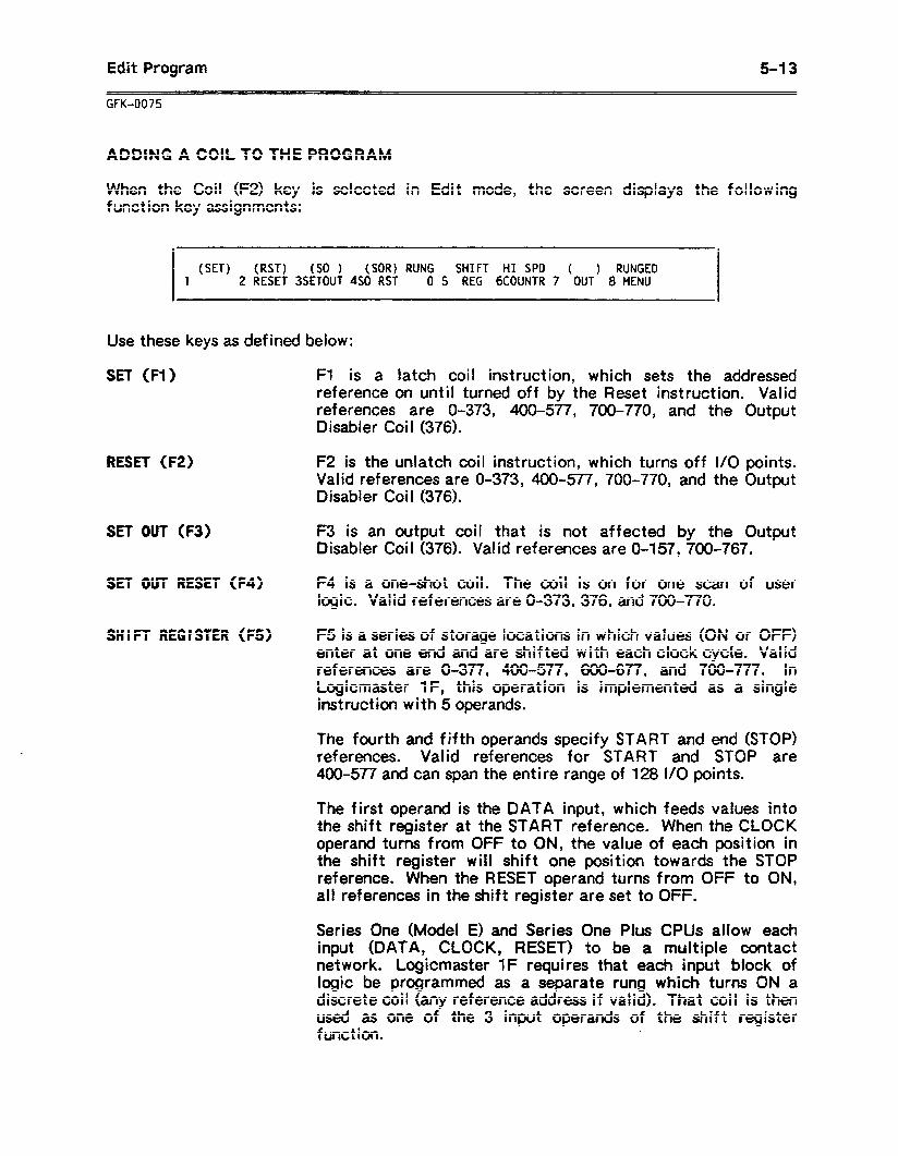
Edit Program
GFK-0075
5-l 3
ADDING A COIL TO THE PROGRAM
When the Coil (F2) key is selected in Edit mode, the screen displays the following function key assignments:
(SET) (RST) (SO ) (SOR) RUNG SHIFT HI SPD ( ) RUNGED 1 2 RESET 3SETOUT 4S0 RST 0 5 REG 6COUNTR 7 OUT 8 MENU
Use these keys as defined below:
SET (Fl) Fl is a latch coil instruction, which sets the addressed reference on until turned off by the Reset instruction. Valid references are O-373, 400577, 700-770, and the Output Disabler Coil (376).
RESET (F2) F2 is the unlatch coil instruction, which turns off I/O points. Valid references are O-373, 400-577, 700-770, and the Output Disabler Coi I (376).
SET OUT (F3) F3 is an output coil that is not affected by the Output Disabler Coil (376). Valid references are O-157, 700-767.
SET OUT RESET (F4) F4 is a one-shot coil. The coil is on for one scan of user logic. Valid references are O-373, 376, and 700-770.
SHIFT REGISTER (FS) F5 is a series of storage locations in which values (ON or OFF) enter at one end and are shifted with each clock cycle. Valid references are O-377, 400-577, 600-677, and 700-777. In Logicmaster IF, this operation is implemented as a single instruction with 5 operands.
The fourth and fifth operands specify START and end (STOP) references. Valid references for START and STOP are 400-577 and can span the entire range of 128 I/O points.
The first operand is the DATA input, which feeds values into the shift register at the START reference. When the CLOCK operand turns from OFF to ON, the value of each position in the shift register will shift one position towards the STOP reference. When the RESET operand turns from OFF to ON, all references in the shift register are set to OFF.
Series One (Model E) and Series One Plus CPUs allow each input (DATA, CLOCK, RESET) to be a multiple contact network. Logicmaster 1F requires that each input block of logic be programmed as a separate rung which turns ON a discrete coil (any reference address if valid). That coil is then used as one of the 3 input operands of the shift register function.
5-l 4 .
Edit Program
GFK-0075
HIGH SPEED COUNTER (F6) The High Speed Counter is implemented in hardware and can
achieve much higher update frequencies than the CPU counter functions which increment once per scan. Valid references are 100-l 07.
OUT (F7)
RUNGED MENU (F8)
Use F7 to define a coil for a rung of logic. Stays ON as long as power is received. Valid references are O-373, 376, and 700-770.
Use F8 to return to the Runged Menu function key assignments.
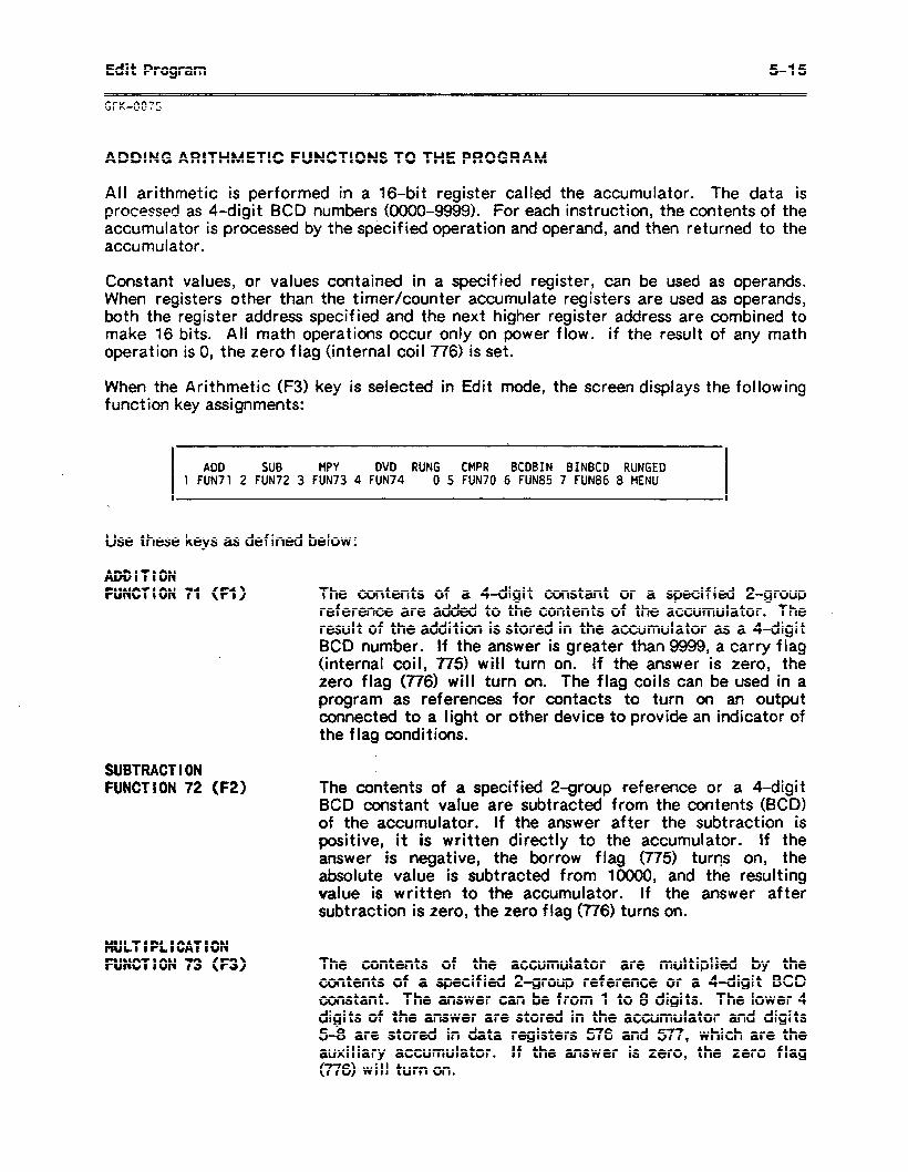
Edit Program 5-15
WK-0@75
ADDIIG ARITHMETIC FUNCTIONS TO THE PROGRAM
All arithmetic is performed in a 16.bit register called the accumulator. The data is processed as 4-digit BCD numbers (oooO-9999). For each instruction, the contents of the accumulator is processed by the specified operation and operand, and then returned to the accumulator.
Constant values, or values contained in a specified register, can be used as operands. When registers other than the timer/counter accumulate registers are used as operands, both the register address specified and the next higher register address are combined to make 16 bits. All math operations occur only on power flow. if the result of any math operation is 0, the zero flag (internal coil 776) is set.
When the Arithmetic (F3) key is selected in Edit mode, the screen displays the following function key assignments:
I I ADD SUB MPY DVD RUNG CMPR BCDBIN BINBCD RUNGED
1 FUN71 2 FUN72 3 FUN73 4 FUN74 0 5 FUN70 6 FUN85 7 FUN86 8 MENU I
Use these keys as defined below:
ADDITION FUNCTION 71 (Fl)
.
The contents of a 4-digit constant or a specified Z-group reference are added to the contents of the accumulator. The result of the addition is stored in the accumulator as a 4-digit BCD number. If the answer is greater than 9999, a carry flag (internal coil, 775) will tufn on. If the answer is zero, the zero flag (776) will turn on. The flag coils can be used in a program as references for contacts to turn on an output connected to a light or other device to provide an indicator of the flag conditions.
SUBTRACT I ON FUNCTION 72 (F2)
MULTIPLICATION FUNCTION 73 (F3)
The contents of a specified Z-group reference or a 4-digit BCD constant value are subtracted from the contents (BCD) of the accumulator. If the answer after the subtraction is positive, it is written directly to the accumulator. If the answer is negative, the borrow flag (775) turns on, the absolute value is subtracted from 10000, and tne resulting value is written to the accumulator. If the answer after subtraction is zero, the zero flag (776) turns on.
The contents of the accumulator are multiplied by the contents of a specified 2-group reference or a 4-digit BCD constant. The answer can be from 1 to 8 digits. The lower 4 digits of the answer are stored in the accumulator and digits 5-8 are stored in data registers 576 and 577, which are the auxiliary accumulator. If the answer is zero, the zero flag (776) will turn on.
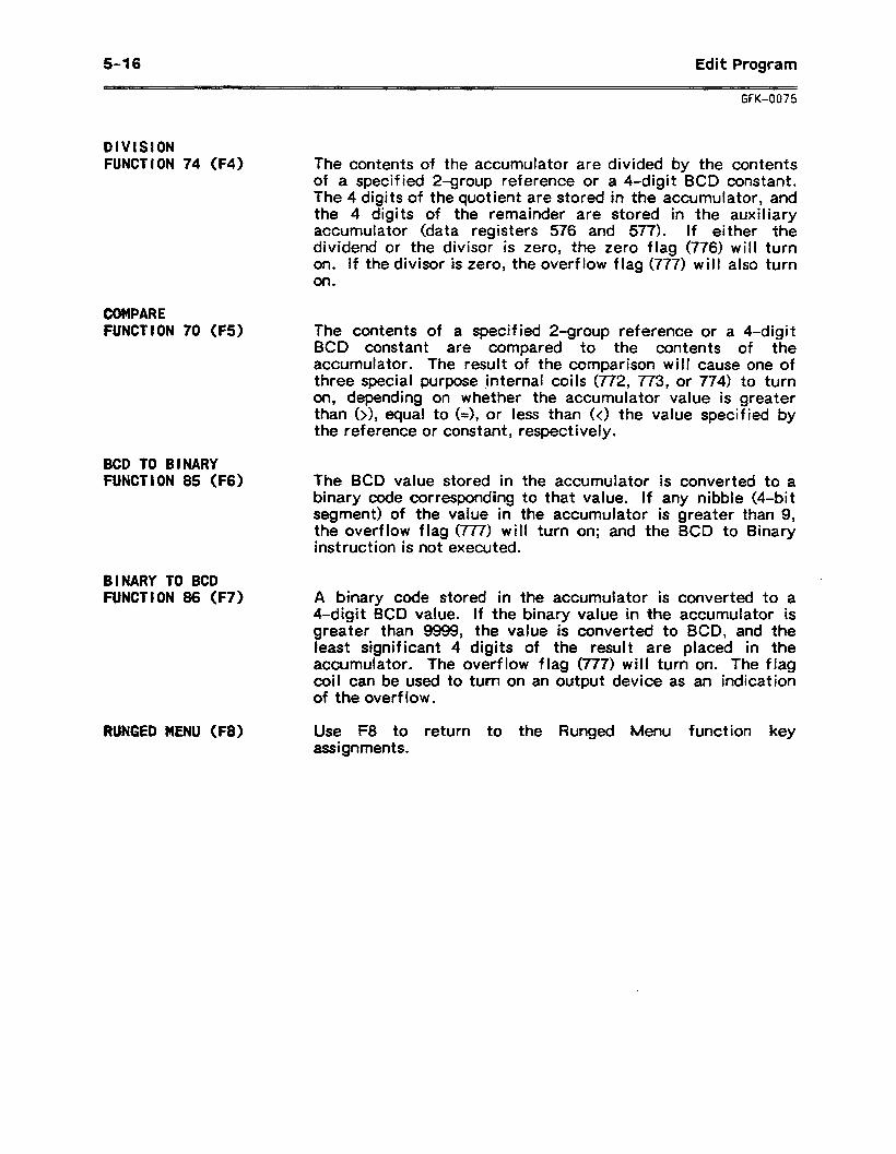
5-l 6 Edit Program
GFK-0075
DIVISION FUNCTION 74 (F4) The contents of the accumulator are divided by the contents
of a specified Z-group reference or a 4-digit BCD constant. The 4 digits of the quotient are stored in the accumulator, and the 4 digits of the remainder are stored in the auxiliary accumulator (data registers 576 and 577). If either the dividend or the divisor is zero, the zero flag (776) will turn on. If the divisor is zero, the overflow flag (777) will also turn on.
COMPARE FUNCTION 70 (F5)
BCD TO BINARY FUNCTION 85 (F6)
BINARY TO BCD FUNCTION 86 (F7)
RUNGED MENU (F8)
The contents of a specified 2-group reference or a 4-digit BCD constant are compared to the contents of the accumulator. The result of the comparison will cause one of three special purpose *internal coils (772, 773, or 774) to turn on, depending on whether the accumulator value is greater than (>), equal to (=), or less than (0 the value specified by the reference or constant, respectively.
The BCD value stored in the accumulator is converted to a binary code corresponding to that value. If any nibble (4.bit segment) of the value in the accumulator is greater than 9, the overflow flag (777) will turn on; and the BCD to Binary instruction is not executed.
A binary code stored in the accumulator is converted to a 4-digit BCD value. If the binary value in the accumulator is greater than 9999, the value is converted to BCD, and the least signif icant 4 digits of the result are placed in the accumulator. The overflow flag (777) will turn on. The flag coil can be used to turn on an output device as an indication of the overflow.
Use F8 to return to the Runged Menu function key assignments.
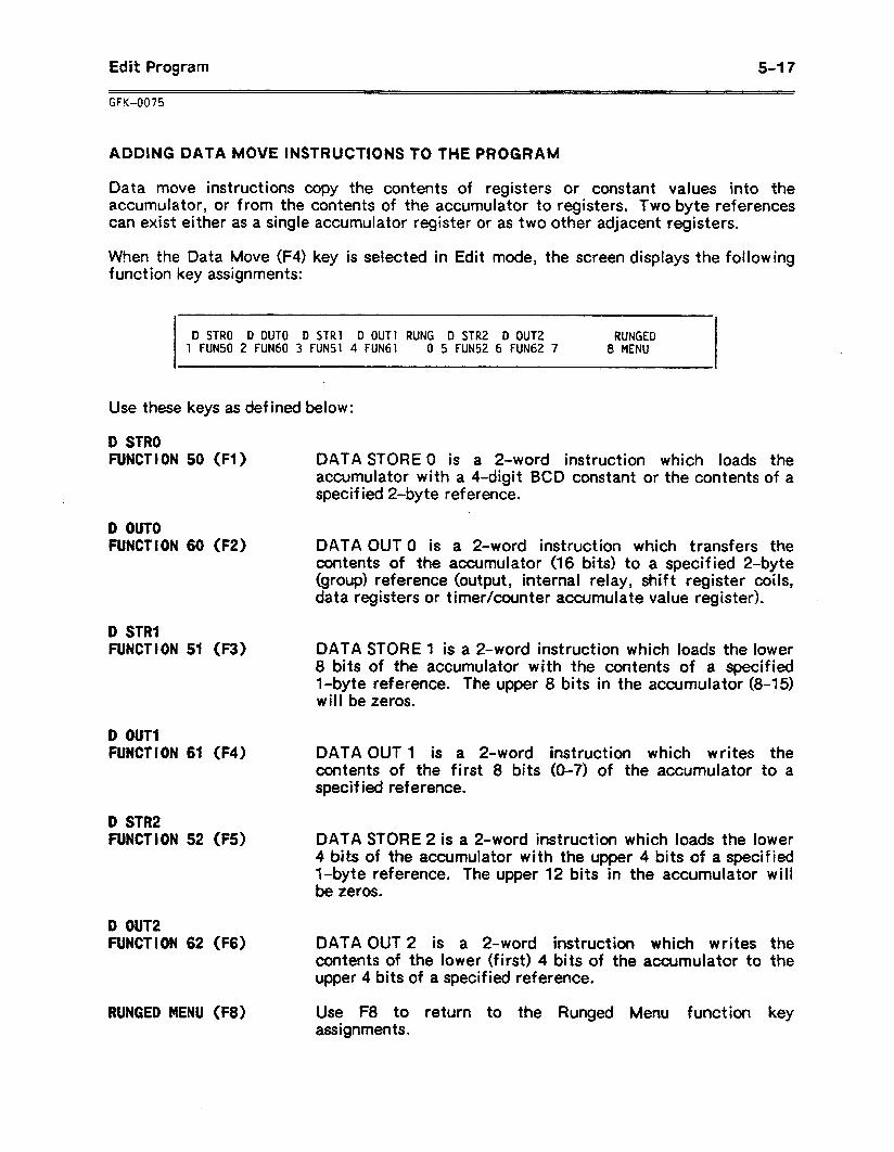
Edit Program 5-I 7
ADDiNG DATA MOVE INSTRUCTIONS TO THE PROGRAM
Data move instructions copy the contents of registers or constant values into the accumulator, or from the contents of the accumulator to registers. Two byte references can exist either as a single accumulator register or as two other adjacent registers.
When the Data Move (F4) key is selected in Edit mode, the screen displays the following function key assignments:
D STRO D OUT0 D STRl D OUT1 RUNG D STR2 D OUT2 RUNGED 1 FUN50 2 FUN60 3 FUN51 4 FUN61 0 5 FUN52 6 FUN62 7 8 MENU
Use these keys as defined below:
D STRO FUNCTION 50 (Fl) DATA STORE 0 is a 2-word instruction which loads the
accumulator with a 4-digit BCD constant or the contents of a
i specified 2-byte reference.
D OUT0 FUNCTION 60 (F2) DATA OUT 0 is a 2-word instruction which transfers the
contents of the accumulator (16 bits) to a specified 2-byte (group) reference (output, internal relay, shift register coils, data registers or timer/counter accumulate value register).
D STRl FUNCTION 51 (F3)
D OUT1 FUNCTION 61 (F4)
D STR2 FUNCTION 52 (FS)
D OUT2 FUNCTION 62 (F6)
RUNGED MENU (F8)
DATA STORE 1 is a 2-word instruction which loads the lower 8 bits of the accumulator with the contents of a specified l-byte reference. The upper 8 bits in the accumulator (8-15) will be zeros.
DATA OUT 1 is a 2-word instruction which writes the contents of the first 8 bits (O-7) of the accumulator to a specified reference.
DATA STORE 2 is a 2-word instruction which loads the lower 4 bib of the accumulator with the upper 4 bits of a specified I-byte reference. The upper 12 bits in the accumulator will be zeros.
DATA OUT 2 is a 2-word instruction which writes the contents of the lower (first) 4 bits of the accumulator to the upper 4 bits of a specified reference.
Use F8 to return to the Runged Menu function key assignments.
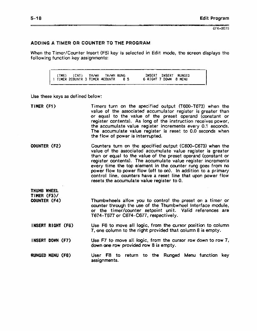
5-18 Edit Program
GFK-0075
ADDING A TIMER OR COUNTER TO THE PROGRAM
When the Timer/Counter insert (F5) key is selected in Edit mode, the screen displays the folldwing function key assignments:
(TMR) (CW TH/WH TH/WH RUNG INSERT INSERT RUNGED 1 TIMER ZCOUNTR 3 TIMER 4COUNTR 0 5 6 RIGHT 7 DOWN 8 MENU
Use these keys as defined below:
TIMER (Fl) Timers turn on the specified output (T600-T673) when the
‘COUNTER (F2)
.
THUMB WHEEL TIMER (F3)/ COUNTER (F4)
INSERT RIGHT (F6)
INSERT DOWN (F7)
RUNGED MENU (F8)
value of the associated accumulator register is greater than or equal to the value of the preset operand (constant or register contents). As long of the instruction receives power, the accumulate value register increments every 0.1 seconds. The accumulate value register is reset to 0.0 seconds when the flow of power is interrupted.
Counters turn on the specified output (C6OOC673) when the value of the associated accumulate value register is greater than or equal to the value of the preset operand (constant or register contents). The accumulate value register increments every time the top element in the counter rung goes from no power flow to power flow (off to on). In addition to a primary contcol line, counters have a reset line that upon power flow resets .the accumulate value register to 0.
Thumbwheels allow you to control the preset on a timer or counter through the use of the Thumbwheel Interface module, or the timer/counter setpoint unit. Valid references are T674-T677 or C674-C677, respectively.
Use F6 to move all logic, f ram the cursor position to column 7, one column to the right provided that column 8 is empty.
&e F7 to move all logic, from the cursor row down to row 7, down obae! ~QW provided row 8 is empty.
User F8 to return to the Runged Menu function key assignments.
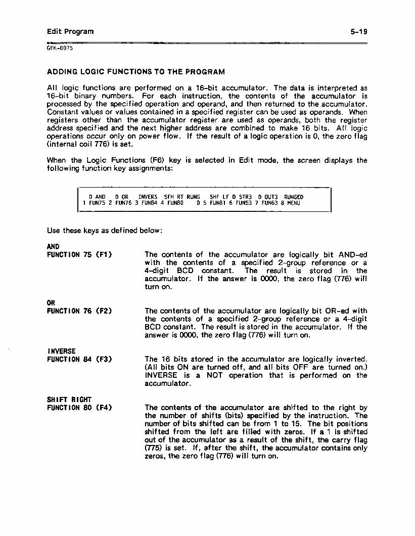
Edit Program 5-l 9
GFK-0075
ADDING LOGIC FUNCTIONS TO THE PROGRAM
All logic functions are performed on a 16.bit accumulator. The data is interpreted as 16.bi t binary numbers. For each instruction, the contents of the accumulator is processed by the specified operation and operand, and then returned to the accumulator. Constant values or values contained in a specified register can be used as operands. When registers other than the accumulator register are used as operands, both the register address specified and the next higher address are combined to make 16 bits. All logic operations occur only on power flow. If the result of a logic operation is 0, the zero flag (internal coil 776) is set.
When the Logic Functions (F6) key is selected in Edit mode, the screen displays the fol lowing function key assignments:
D AND D OR INVERS SFH RT RUNG SHF LF D STR3 D OUT3 RUNGED 1 FUN75 2 FUN76 3 FUN84 4 FUN80 0 5 FUN81 6 FUN53 7 FUN63 8 MENU
Use these keys as defined below:
AND FUNCTION 75 (Fl) The contents of the accumulator are logically bit AND-ed
with the contents of a specified 2-group reference or a 4-digit BCD constant. The result is stored in the accumulator. If the answer is 0000, the zero flag (776) will turn on.
OR FUNCTION 76 (F2) The contents of the accumulator are logically bit OR-ed with
the contents of a specified 2-group reference or a 4-digit BCD constant. The result is stored in the accumulator. If the answer is 0000, the zero flag (776) will turn on.
I NVERSE FUNCTION 84 (F3) The 16 bits stored in the accumulator are logically inverted.
(All bits ON are INVERSE is a accumulator.
turned off, and all bits OFF -are turned on.) NOT operation that is performed on the
SHIFT RIGHT FUNCTION 80 (F4) The contents of the accumulator are shifted to the right by
the number of shifts (bits) specified by the instruction. The number of bits shifted can be from 1 to 15. The bit positions shifted from the left are filled with zeros. If a 1 is shifted out of the accumulator as a result of the shift, the carry flag (775) is set. If, after dAe shift, the accumulator contains only zeros, the zero flag (776) will turn on.
5-20 Edit Program
GFK-0075
SH I FT LEFT FUNCTION 81 (FS) The contents of the accumulator are shifted to the left by the
number of shifts (bits) specified by the instruction. The number of bits shifted can be from 1 to 15. The bit positions shifted from the right are filled with zeros. If a 1 is shifted out of the accumulator as a result of the shift, the carry flag (775) will turn on. If, after the shift, the accumulator contains only zeros, the zero flag(776) will turn on.
D STR3 FUNCTION 53 (F6) DATA STORE 3 is a Z-word instruction which loads the lower
4 bits of the accumulator with the lower 4 bits of a specified 1 -byte reference. The upper 12 bits in the accumulator will be zeros.
D OUT3 FUNCTION 63 (F7) DATA OUT 3 is a 2-word instruction which writes the
contents of the lower 4 bits of the accumulator to the lower 4 bits of a specified l-byte reference.
RUNGED MENU (F8) Use F8 to return to the Runged Menu function key assignments.
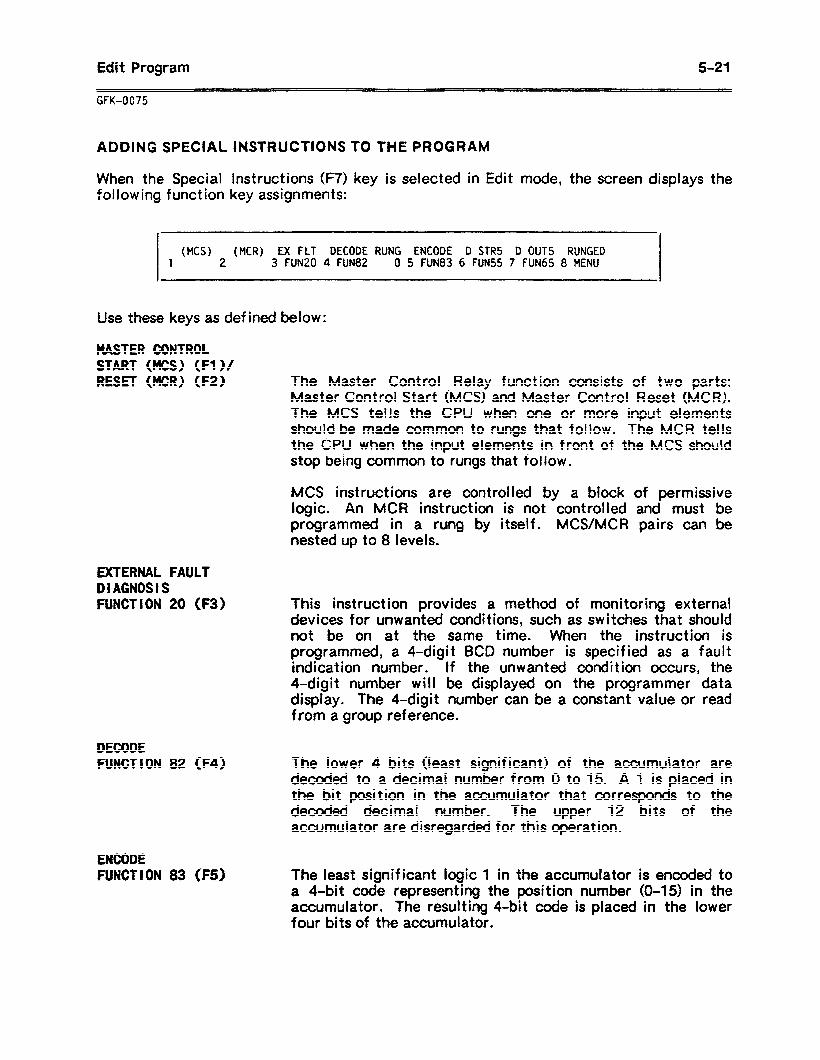
Edit Program 5-21
GFK-0075
ADDING SPECIAL INSTRUCTIONS TO THE PROGRAM
When the Special Instructions (F7) key is selected in Edit mode, the screen displays the following function key assignments:
WCS) (MCR) EX FLT DECODE RUNG ENCODE D STR5 D OUT5 RUNGED 1 2 3 FUN20 4 FUN82 0 5 FUN83 6 FUN55 7 FUN65 8 MENU
Use these keys as defined below:
MASTER CONTROL START (KS) (Fl)/ RESET (MCR) (FZ)
aCTERNAL FAULT DIAGNOSIS FUNCTION 20 (F3)
DECODE FUNCTION 82 (F4)
ENCODE FUNCTION 83 (F5)
The Master Control Relay function consists of two parts: Master Control Start (MCS) and Master Control Reset (MCR). The MCS tells the CPU when one or more input elements should be made common to rungs that follow. The MCR tells the CPU when the input elements in front of the MCS should stop being common to rungs that follow.
MCS instructions are controlled by a block of permissive logic. An MCR instruction is not controlled and must be programmed in a rung by itself. MCS/MCR pairs can be nested up to 8 levels.
This instruction provides a method of monitoring external devices for unwanted conditions, such as switches that should not be on at the same time. When the instruction is programmed, a 4-digit BCD number is specified as a fault indication number. If the unwanted condition occurs, the 4-digit number will be displayed on the programmer data display. The 4-digit number can be a constant value or read from a group reference.
The lower 4 bits (least signif icant) of the accumulator are decoded to a decimal number from 0 to 15. A 1 is placed in the bit position in the accumulator that corresponds to the decoded decimal number. The upper 12 bits of the accumulator are disregarded for this operation.
The least significant logic 1 in the accumulator is encoded to a 4-bit code representing the position number (O-15) in the accumulator. The resulting 4-bit code is placed in the lower four bits of the accumulator.
5-22 Edit Program
GFK-0075
D STR5 FUNCTION 55 (F6) DATA STORE 5 is a 2-word instruction which loads the
accumulator with a BCD value from the 2-byte contents of a f6-circuit input or output module.
The contents of the specified I/O reference is stored in the lower 8 bits of the accumulator. The contents of the specified i/O reference +lOO is placed in the higher 8 bits of the accumulator.
Valid references are RO-I?5 For example, if the operand is R2, then R2 -(l/O points 20-27) are placed in the lower 8 bits of the accumulator. R12 (l/O points 120427) are placed in the upper 8 bits.
D OUTS FUNCTION 65 (F7)
RUNGED MENU (F8)
DATA OUT 5 is a 2-word instruction which writes the contents of the accumulator to a 2-byte reference which must be a 16-circuit input or output module.
The lower 8 bits of the accumulator are stored in the specified register reference. The upper 8 bits are stored in the specified reference +lOO. Valid references are RO-R5.
Use F8 to return to the Runged Menu function key assignments.
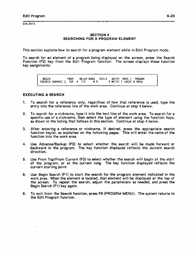
Ecdi t Program 5-23
GFK-0075
SECTION 4 SEARCHING FOR A PROGRAM ELEMENT
This section explains how to search for a program element while in Edit Program mode.
To search for an element of a program being displayed on the screen, press the Search Function (FZ) key from the Edit Program function. The screen displays these function key assignments:
I
I BEGIN FROM RELAY RUNG COILS ARITH MOVE / PROGRM 1SEARCH ZADVNCE 3 TOP 4 TIC # 5 6 METIC 7 LOGIC 8 MENU
EXECUTING A SEARCH
1 .
2 .
3 .
4 .
5 .
6 .
8 .
To search for a reference only, regardless of how that reference is used, type the entry into the reference line of the work area. Continue at step 4 below.
To search for a nickname, type it into the text line of the work area. To search for a specific use of a nickname, then select the type of element using the function keys, as shown in the listing that follows in this section. Continue at step 4 below.
After entering a reference or nickname, if desired, press the appropriate search function key(s), as explained on the following pages. This will enter the name of the function into the work area.
Use Advance/Backup (F2) to select whether the search will be made forward or backward in the program. The key function displayed reflects the current search direct ion.
Use From Top/From Current (F3) to’select whether the search will begin at the start of the program, or at the current rung. The key function displayed reflects the current starting point.
Use Begin Search (Fl) to start the search for the program element indicated in the work area. When the element is located, that element will be displayed at the top of the screen. To repeat the search, adjust the parameters as needed, and press the Begin Search (Fl) key again.
To exit from the Sea&~ function, press F8 (PROGRM MENU). The system returns to the Edit Program function.
5-24 Edit Program
GFK-0075
“Wildcard” Nickname Search
An asterisk (*) can be used to search the nickname. For example, entering
1 . Enter the nickname in the work at the end.
for similar nicknames. It must be used at the end of - PB* would search for PBl, PB2, or PB3.
area, using the * to replace the variable characters
2 . Use From Top/From Current (F3) to select the starting point.
3 . Use Advance/Backup (F2) to select the direction of the search.
4 . Use Begin Search (Fl) to start the search.
SEARCH KEYS: DEFINITIONS
The Search Function keys are summarized below.
BEGIN SEARCH (Fl) Use Fl to start the search for the element defined in the work area. Selections relating to the search operation must be made prior to pressing this key.
ADVANCE/BACKUP (F2) F2 toggles the search direction between forward and reverse.
FROM TOP/CURRENT (F3) F3 toggles the starting point for the search between the top .of the program and the current cursor location.
Each of the following four function keys activates a menu of instructions. Selecting one of the instruction soft keys within each menu will place the instruction in the work area and specify a search for that instruction. The instructions accessed from each menu are I isted below:
RELAYS a TIMERS/COUNTERS (F4)
COILS (FS)
ARITHMETIC INSTRUCTIONS (F6)
DATA MOVE, LOGIC, and SPECIAL INSTRUCTIONS (F7)
Use F4 to access Relays, Drum Sequencers, Timers, and Counters.
Use F5 to access Out, Set, Reset, Set Out, and Set Out Reset Coils, Shift Registers, and High Speed Counters.
Use F6 to access Addition, Subtraction, Multiplication, Division, Compare, BCD to Binary, and Binary to BCD instruct ions.
Use F7 to access DSTRO, DSTRl, DSTRZ, DOUTO, DOUTl, DOUT2, AND, CR, Invert, Shift Right, Shift Left, DSTR3, MCS, MCR, External Fault Diagnosis, Decode, Encode, DSTRS, DOUTS, and Bad Opcode instructions.
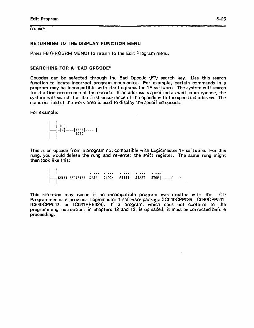
Edit Program s-25
_ ~_ ~_ __ GFK-0075
RETURNING TO THE DISPLAY FUNCTION MENU
Press F8 (PROGRM MENU) to return to the Edit Program menu.
SEARCHING FOR A “BAD OPCODE”
Opcodes can be selected through the Bad Opcode (F7) search key. Use this search function to locate incorrect program mnemonics. For example, certain commands in a program may be incompatible with the Logicmaster 1Fsoftware. Thesystem will search for the first occurrence of the opcode. If an address is specified as well as an opcode, the system will search for the first occurrence of the opcode with the specified address. The numeric field of the work area is used to display the specified opcode.
For example:
00 4 -- I FFFFl
5050 -- I
This is an opcode from a program not compatible with Logicmaster 1 F soft ware. For this rung, you would delete the rung and re-enter the shift register. The same rung might then look like this:
* *** * RR* * *** x RRR * *RX
- SHIFT REGISTER DATA CLOCK RESET START STOP[--( )
This situation may occur if an incompatible program was created with the LCD Programmer or a previous Logicmaster 1 software package (IC64OCPP539, IC64OCPP541, IC64OCPPM3, or IC641PFE626). If a program, which does not conform to the programming instructions in chapters 12 and 13, is uploaded, it must be corrected before proceeding.
5-26 Edit Program
GFK-0075
SECTION 5 LADDER DIAGRAM FILE EDITING
This section explains:
l HOW to save part of a program in a separate file. This file has the extension .SDE and is called a Side File.
a How to copy all of an .SDE file into another program.
l How to copy all of the ladder logic contained in a .LAD file into another program.
COPYING RUNGS TO A SIDE (.SDE) FILE
Follow the steps below to copy rungs from a program into a separate file called a Side file.
1 . With the program displayed in Edit mode, determine the exact number of rungs you want to copy into the Side file.
2 . Place the cursor at the first rung to be copied.
3. Use the Select key to move the cursor in the work area to the top line, and enter a name for the file. The system will automatically add the extension .SDE to this file name when the file is created.
4 . Use the Select key to move the cursor in the work area to the bottom line, and enter the number of rungs to be copied to the file.
5 . Press ALT-W. The system creates a new file, consisting of the specified rungs.
Edit Program 5-27
ADDING THE .SDE OR .LAD FILE TO A PROGRAM
The entire content of the .SDE or .LAD file can be added to the ladder diagram program if no file name is active.
Follow the steps below:
1 .
2 .
3 .
With the program to receive the added rungs displayed in Edit mode, place the cursor on the rung prior to which the extra rungs should be added.
Use the Select key to move the cursor in the work area to the top line, and enter the name of the .LAD or .SDE file. For the .LAD file, you must enter the extension .LAD after the file name.
Press ALT-G. The extra rungs appear in the display.
Using these functions can create an incorrect program. For example, it is possible to insert an extra MCS instruction that is not matched with a corresponding MCR. This situation may also occur if an incompatible program was created with the LCD Programmer or a previous Logicmaster 1 software package (IC64OCPP539, IC64OCPP541, IC64OCPP543, or I C641 PFE626) s If 6 program, which does not conform to the programming instruc.t ions in chapters 12 and 13, is uploaded, it must be corrected before proceeding.

Annotation .
6-l
CHAPTER 6 ANNOTATION
Annotation is an important feature of the Logicmaster 1 Family (LlF) software package. It can be used to add explanatory text to a ladder logic program. The annotation can be names and nicknames for individual references, and longer blocks of text used for rung explanations and coil labels within the program.
This chapter explains how to create, how to display, and how to print annotation. Refer to the appropriate sections:
Section 1. Types of Annotation: This section introduces the four types of annotation. Read this section before going to sections 2 through 4.
Section 2. Enter@ and Editing Annotation: Section 2 explains how to create annotation, as part of a ladder logic program, or separately. It also explains how to adjust the annotation when rungs are added or deleted in a program. Finally, this section gives instructions for creating a separate file to contain additional annotation text for printing.
Section 3. Viewing Annotation in Display-r&m Mode: Section 3 summarizes the ways in which annotation can be displayed.
Section 4. Printing Annotation: This section supplements the information on printing (refer to chapter 8) with specific instructions for printing annotation.
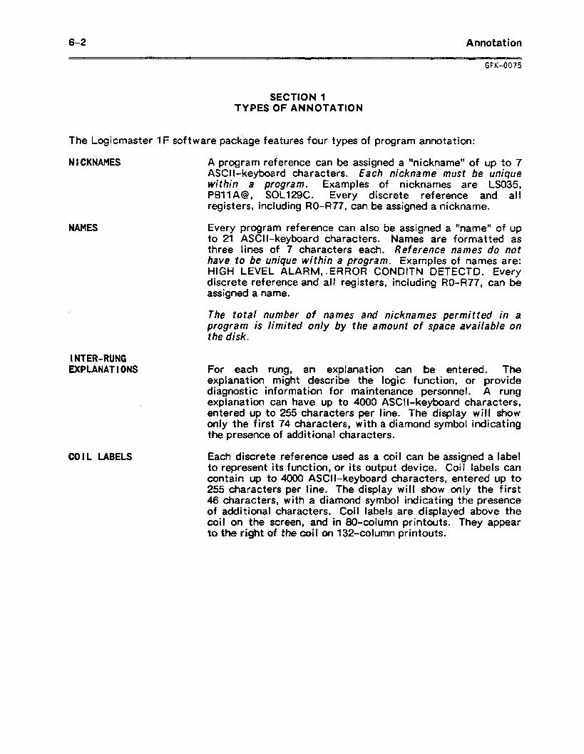
6-2 Annotation
GFK-0075
SECTION 1 TYPES OF ANNOTATION
The Logicmaster 1F software package features four types of program annotation:
NICKNAMES A program reference can be assigned a *‘nickname” of up to 7 ASCII-keyboard characters. Each nickname must be unique within a program. Examples of nicknames are LS035, PBllA@, SOL129C. Every discrete reference and all registers, including RO-R77, can be assigned a nickname.
I NTER-RUNG EXPLANAT I ONS
COIL LABELS
Every program reference can also be assigned a “name” of up to 21 ASCII-keyboard characters. Names are formatted as three lines of 7 characters each. Reference names do not have to be unique within a program. Examples of names are: HIGH LEVEL ALARM, *ERROR CONDITN DETECTD. Every discrete reference and all registers, including RO477, can be assigned a name.
The total number of names and nicknames permitted in a program is limited only by the amount of space available on the disk.
For each rung, an explanation can be entered. The explanation might describe the logic function, or provide diagnostic information for maintenance personnel. A rung explanation can have up to 4000 ASCII-keyboard characters, entered up to 255 characters per line. The display will show only the first 74 characters, with a diamond symbol indicating the presence of addit ional characters.
Each discrete reference used as a coil can be assigned a label to represent its function, or its output device. Coil labels can contain up to 4000 ASCII-keyboard characters, entered up to 255 characters per line. The display will show only the first 46 characters, with a diamond symbol indicating the presence of additional characters. Coil labels are displayed above the coil on the screen, and in 80.column printouts. They appear to the right 0f ahe coil on 132.column printouts.
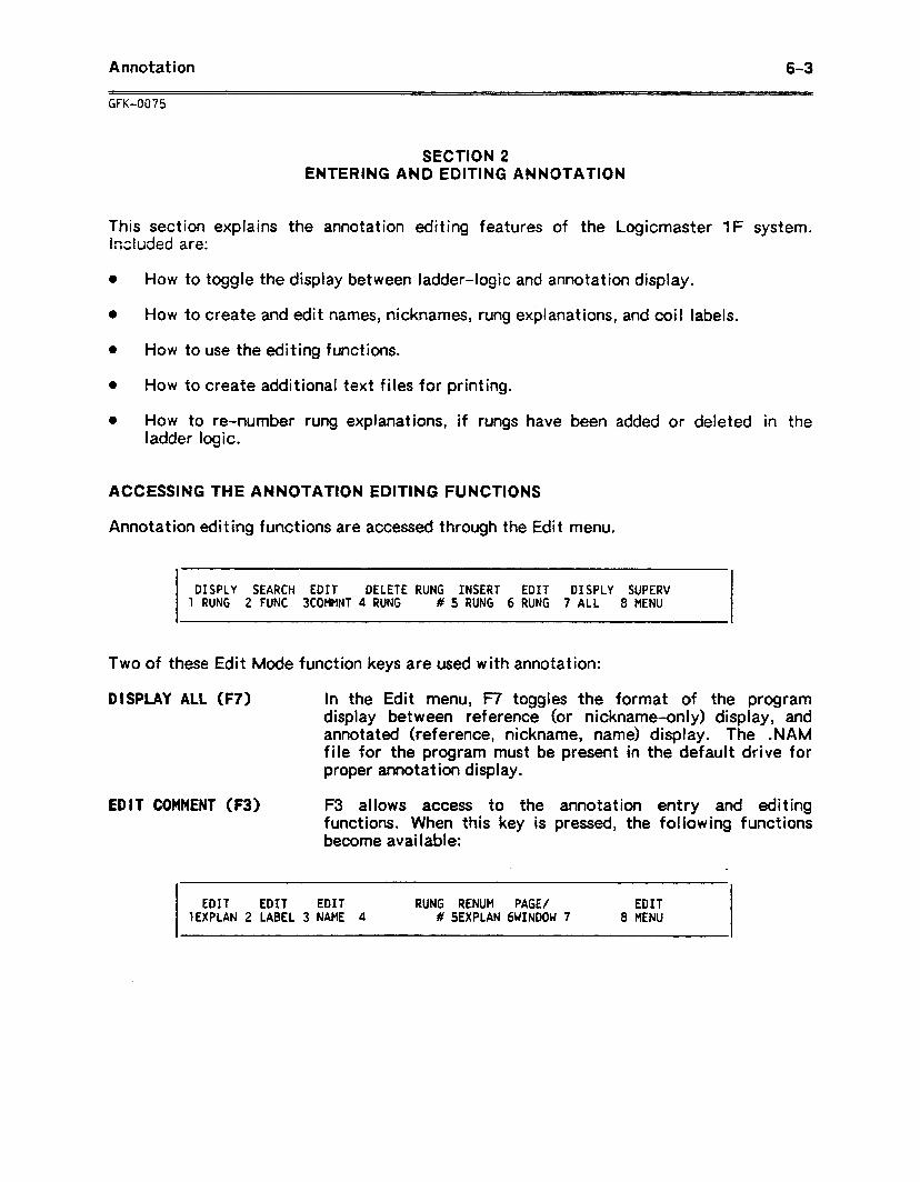
Annotation 6-3
GFK-0075
SECTION 2 ENTERING AND EDITING ANNOTATION
This section explains the annotation editing features of the Logicmaster 1F system. Muded are:
0 How to
l How to
0 How to
0 How to
toggle the display between ladder-logic and
create and edit names, nicknames, rung exp
use the editing functions.
create additional text files for printing.
annotation display .
Ilanat ions, and coi I labels.
0 How to re-number rung explanations, if rungs have been added or ladder logic.
ACCESSING THE ANNOTATION EDITING FUNCTIONS
Annotation editing functions are accessed through the Edit menu,
deleted in the
DISPLY SEARCH EDIT DELETE RUNG INSERT EDIT DISPLY SUPERV 1 RUNG 2 FUNC 3COMMNT 4 RUNG # 5 RUNG 6 RUNG 7 ALL 8 MENU
Two of these Edit Mode function keys are used with annotation:
D I SPLAY ALL (F7) in the Edit menu, F7 toggles the format of the program display bet ween reference (or nickname-only) display, and annotated (reference, nickname, name) display. The .NAM file for the program must be present in the default drive for proper annotation display.
EDIT COMMENT (F3) F3 allows access to the annotation entry and editing functions. When this key is pressed, the following functions become available:
EDIT EDIT EDIT RUNG RENUM PAGE/ EDIT 1EXPLAN 2 LABEL 3 NAME 4 # SEXPLAN GWINDOW 7 8 MENU
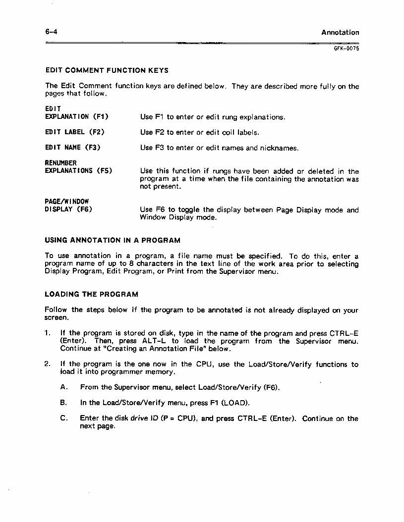
6-4 Annotation
GFK-0075
EDIT COMfvlENT FUNCTION KEYS
The Edit Comment function keys are defined below. They are described more fully on the pages that follow.
EDIT EXPLANAT I ON (Fl ) Use Fl to enter or edit rung explanations.
EDIT LABEL (F2) Use F2 to enter or edit coil labels.
EDIT NAME (F3) Use F3 to enter or edit names and nicknames.
RENUMBER EXPUNAT I ONS (FS) Use this function if rungs have been added or deleted in the
program at a time when the file containing the annotation was not present.
PAGE/WINDOW DISPLAY (F6) Use F6 to toggle the display between Page Display mode and
Window Display mode.
USING ANNOTATION IN A PROGRAM
To use annotation in a program, a file name must be specified. To do this, enter a program name of up to 8 characters in the text line of the work area prior to selecting Display Program, Edit Program, or Print from the Supervisor menu.
LOADING THE PRO1 C 4
Follow the steps be screen.
1 . If the program (Enter). Then,
;iRAM
ow if the program to be annotated is not already displayed on your
s stored on disk, type in the name of the program and press CTRL-E press ALT-L to load the program from the Supervisor menu.
Continue at Xreat ing an Annotation Fi lef* below.
2 . If the program is the one now in the CPU, use the Load/Store/Verify functions to load it into programmer memory.
A . From the Supervisor menu, select Load/Store/Verify (F6).
6 . In the Load/StoreNerify menu, press Fl (LOAD).
C . Enter the disk drive ID fP = CPU), and press CTRL-E (Enter). Continue on the next page.
Annotation 6-S
CREATING AN ANNOTATION FILE
The program name must be entered from the Supervisor menu to use annotation. If you have not entered the file name, follow the steps below:
1 . From the Supervisor menu, type in the file name for the pmgram.
2 . To create the file without entering Edit Program mode, press CTRL-E (Enter). The file name will be displayed below the menu selections.
Or, select Edit Program by pressing F2. When the backup prompt is displayed, enter N if no annotation file with the same name already exists, or Y if you want to save a previous version of the file before editing the annotation.
ENTERING NICKNAMES WHEN CREATING A RUNG
Nicknames can be entered when a rung is created, or entered separately. Follow the instructions below to enter a nickname while creating a rung.
1 . Be sure that the program name has been specified from the Supervisor menu.
2 . While entering a program element, the reference is entered in the center line of the work area. To assign a nickname for that reference, enter up to 7 ASCII-keyboard characters in the top line of the work area. For example: LS035, PBllA@, SOL129C.
3 . Press the Shift key and the Enter key at the same time, or press an instruction function key. The system checks whether the reference has been used before in the program, and whether the reference has already been assigned a nickname. If not, that nickname will be assigned to the reference throughout the program. The nickname will be stored on the program disk when the rung is accepted.
If the nickname has already been used, a message is displayed and the nickname is not stored.
If the reference has a prior nickname, a message is displayed requesting confirmation to delete the prior nickname. If confirmed, the new nickname will replace the former one throughout the program. It will be stored on the program diskette.
DELETING A NICKNAME
To delete a nickname, enter the reserved name “noneT’ as the nickname in the top line of the work area. Enter the reference from which the nickname is to be deleted in the center line of the work area. Press the Shift and Enter keys at the same time, or select an instruct ion function key. A message will be displayed, confirming the nickname deletion.
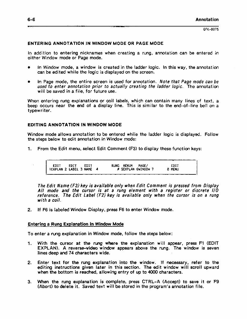
6-6 Annotation
GFK-0075
ENTERING ANNOTATION IN WINDOW MODE OR PAGE MODE
In addition to entering nicknames when creating a rung, annotation can be entered in either Window mode or Page mode.
0 In Window mode, a window is created in the ladder logic. In this way, the annotation can be edited while the logic is displayed on the screen.
0 In Page mode, the entire screen is used for annotation. /Vote that Page mode can be used to enter annotation prior to actually creating the ladder logic. The annotation will be saved in a file, for future use.
When entering rung explanations or coil labels, which can contain many lines of text, a beep occurs near the end of a display line. This is similar to the end-of-line bell on a typewriter.
EDITING ANNOTATION IN WINDOW MODE
Window mode allows annotation to be entered while the ladder logic is displayed. Follow the steps below to edit annotation in Window mode:
1 . From the Edit menu, select Edit Comment (F3) to display these function keys:
v
EDIT EDIT EDIT RUNG RENUM PAGE/ EDIT ‘IEXPLAN 2 LABEL 3 NAME 4 # SEXPLAN 6WINDOW 7 8 EiENU
The Edit Name (F3) key is available only when Edit Comment is pressed from Display All mode and the cursor is at a rung element with a register or discrete l/O reference. The Edit Label (F2) key is available only when the cursor is on a rung with a coil.
2 . If F6 is labeled Window Display, press F6 to enter Window mode.
Entering a Rung Explanation in Window Mode
To enter a rung explanation in Window mode, follow the steps below:
1 . With the cursor at the rung ~faere the explanation will appear, press Fl (EDIT EXPLAN). A reverse-uEb window appears above the rung. The window is seven lines deep and 74 characters wide. _ .
2. Enter text for the rung explanation into the window. If necessary, refer to the editing instructions given later in this section. The edit window will scroll upward when the bottom is reached, allowing entry of up to 4000 characters.
3. When the rung explanation is complete, press CTRL-A (Accept) to save it or F9 (Abort) to delete it. Saved text will be stored in the program’s annotation file.
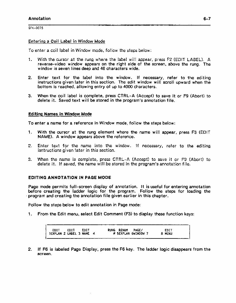
Annotation 6-7
GFK-0075
Entering a Coil Label in Window Mode
To enter a coil label in Window mode, follow the steps below:
1 . With the cursor at the rung where the label will appear, press F2 (EDIT LABEL). A reverse-video window appears on the right side of the screen, above the rung. The window is seven lines deep and 46 characters wide.
2 . Enter text for the label into the window. If necessary, refer to the editing instructions given later in this section. The edit window will scroll upward when the bottom is reached, allowing entry of up to 4000 characters.
3 . When the coil label is complete, press CTRL-A (Accept) to save it or F9 (Abort) to delete it. Saved text will be stored in the program’s annotation file.
Editing Names in Window Mode
To enter a name for a reference in Window mode, follow the steps below:
1 . With the cursor at the rung element where the name will appear, press F3 (EDIT NAME). A window appears above the reference.
2 . Enter text for the name into the window. If necessary, refer to the editing isntructions given later in this section.
3 . When the name is complete, press CTRL-A (Accept) to save it or F9 (Abort) to delete it. If saved, the name will be stored in the program’s annotation file.
EDITING ANNOTATION IN PAGE MODE
Page mode permits full-screen display of annotation. It is useful for entering annotation before creating the ladder logic for the program. Follow the steps for loading the
. program and creating the annotation file given earlier in this chapter.
Follow the steps below to edit annotation in Page mode:
1 . From the Edit menu, select Edit Comment (F3) to display these function keys:
EDIT EDIT EDIT RUNG RENUM PAGE/ EDIT 1EXPLAN 2 LABEL 3 NAME 4 # SEXPLAN 6WINDOW 7 8 MENU
2 . If ~6 is lab&d Page Display, press the F6 key. The ladder logic disappears from the screen.
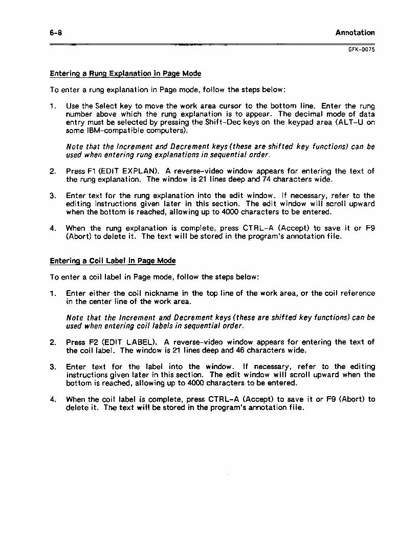
6-8 Annotation
GFK-0075
Entering a Rung Explanation in Page Mode
To enter a rung explanation in Page mode, follow the steps below:
1 .
2 .
3 .
4 .
Use the Select key to move the work area cursor to the bottom line. Enter the rung number above which the rung explanation is to appear. The decimal mode of data entry must be selected by pressing the Shift-Dee keys on the keypad area (ALT-U on some IBM-compatible computers).
Note that the Increment and Decrement keys (these are shifted key functions) can be used when entering rung explanations in sequential order.
Press Fl (EDIT EXPLAN). A reverse-video window appears for entering the text of the rung explanation. The window is 21 lines deep and 74 characters wide.
Enter text for the rung explanation into the edit window. If necessary, refer to the editing instructions given later in this section. The edit window will scroll upward when the bottom is reached, allowing up to 4000 characters to be entered.
When the rung explanation is complete, press CTRL-A (Accept) to save it or F9 (Abort) to delete it. The text will be stored in the program’s annotation file.
Entering a Coil Label in Page Mode
To enter a coil label in Page mode, follow the steps below:
1 .
2 .
3 .
4 .
Enter either the coil nickname in the top line of the work area, or the coi in the center line of the work area.
I reference
Note that the Increment and Decrement keys,(these are shifted key functions) can be used when entering coil labels in sequential order.
Press F2 (EDIT LABEL). A reverse-video window appears for entering the text of the coil label. The window is 21 lines deep and 46 characters wide.
Enter text for the label into the window. If necessary, refer to the editing instructions given later in this section. The edit window will scroll upward when the bottom is reached, allowing up to 4000 characters to be entered.
When the coil label is complete, press CTRL-A (Accept) to save it or F9 (Abort) to delete it. The text will be stored in the program’s annotation file.
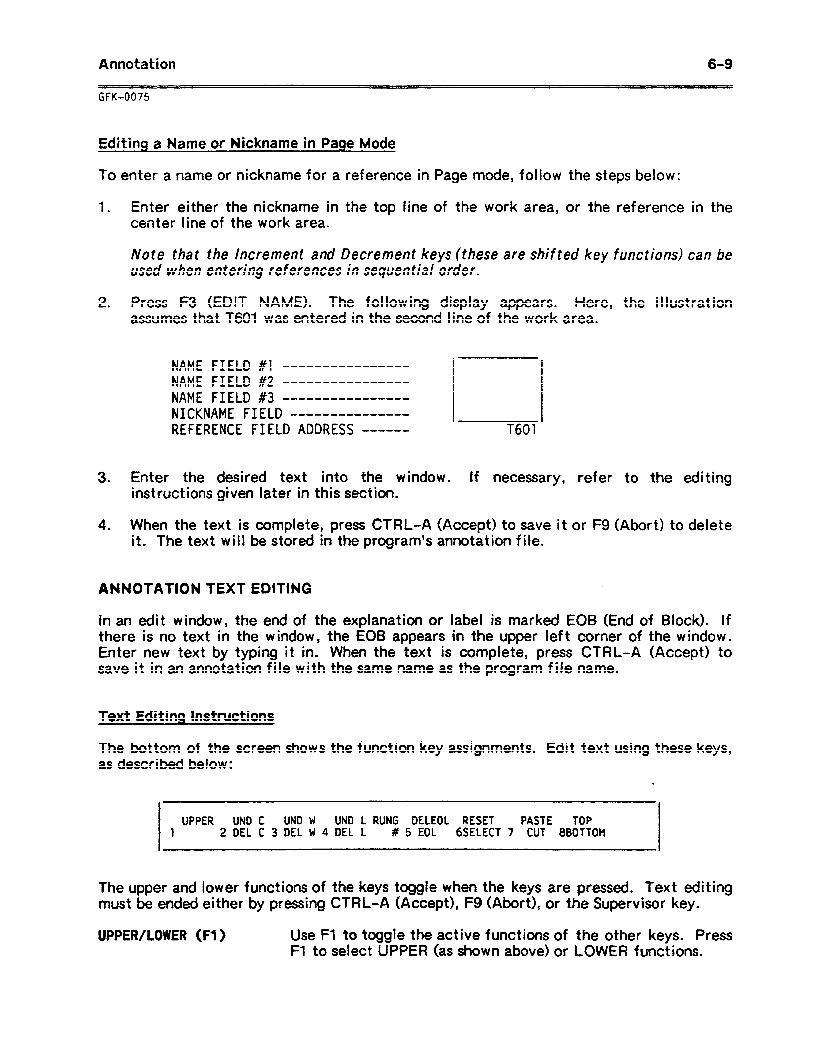
Annotation
GFK-0075
6-9
Editing a Name or Nickname in Page Mode
To enter a name or nickname for a reference in Page mode, follow the steps below:
1 . Enter either the nickname in the top line of the work area, or the reference in the center line of the work area.
Note that the Increment and Decrement keys (these are shifted key functions) can be used when entering references in sequential order.
2 . Press F3 (EDIT NAME). The following display appears. Here, the illustration assumes that T601 was entered in the second line of the work area.
NAME FIELD #l ---------------- NAME FIELD #2 ---------------- NAME FIELD #3 ---------------- NICKNAME FIELD ---------------
REFERENCE FIELD ADDRESS ------
3 . Enter the desired text into the window. instructions given later in this section.
T601
If necessary, refer to the editing
4 . When the text is complete, press CTRL-A (Accept) to save it or F9 (Abort) to delete it. The text will be stored in the program’s annotation file.
ANNOTATION TEXT EDITING
In an edit window, the end of the explanation or label is marked EOB (End of Block). If there is no text in the window, the EOB appears in the upper left corner of the window. Enter new text by typing it in. When the text is complete, press CTRL-A (Accept) to save it in an annotation file with the same name as the program file name.
Text Editing Instructions
The bottom of the screen shows the function key assignments. Edit text using these keys, as described below:
UPPER UND C UND W UND L RUNG DELEOL RESET PASTE TOP 1 2 DEL C 3 DEL W 4 DEL L # 5 EOL 6SELECT 7 CUT 8BOTTOM
The upper and lower functions of the keys toggle when the keys are pressed. Text editing must be ended either by pressing CTRL-A (Accept), F9 (Abort), or the Supervisor key.
UPPER/LOWER (Fl ) Use FI to toggle the active functions of the other keys. Press Fl to select UPPER (as shown above) .or LOWER functions.
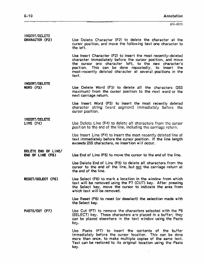
6-l 0 Annotation
GFK-0075
INSERT/DELETE CHARACTER (F2) Use Delete Character (FZ) to delete the character at the
cursor position, and move the following text one character to the left.
Use Insert Character (F2) to‘ insert the most recently-deleted character immediately before the cursor position, and move the cursor one character left, to the new character’s position. This can be done repeatedly, to insert the most-recently deleted character at several positions in the text.
INSERT/DELETE WORD (F3)
INSERT/DELETE LINE (F4)
Use Delete Word (F3) to delete all the characters (255 maximum) from the cursor position to the next word or the next carriage return.
Use insert Word (F3) to insert the most recently deleted character string (word segment) immediately before the cursor position.
Use Delete Line (F4) to delete all characters from the cursor position to the end of the line, including the carriage return.
Use Insert Line (F4) to insert the most recently deleted line of text immediately before the cursor position. If the line length exceeds 255 characters, no insertion will occur.
DELETE END OF LINE/ END OF LINE (FS) Use End of Line (F5) to move the cursor to the end of the line.
Use Delete End of Line (F5) to delete all characters from the cursor to the end of the line, but not the carriage return at the end of the line.
RESET/SELECT (F6) Use Select (F6) to mark a location in the window from which text will be removed using the F7 (CUT) key. After pressing the Select key, move the cursor to indicate the area from which text will be removed.
Use Reset (F6) to reset (or deselect) the selection made with the Select key.
PASTE/CUT (F7) Use Cut 07) to remove the characters selected with the F6 (SELECT) key. These characters are placed in a buffer; they can be placed elsewhere in the text window using the Paste
key .
Use Paste (F7) to insert the contents of the buffer immediately before the cursor location. This can be done more than once, to make multiple copies of the same text. Text can be restored to its original location using the Paste
key .
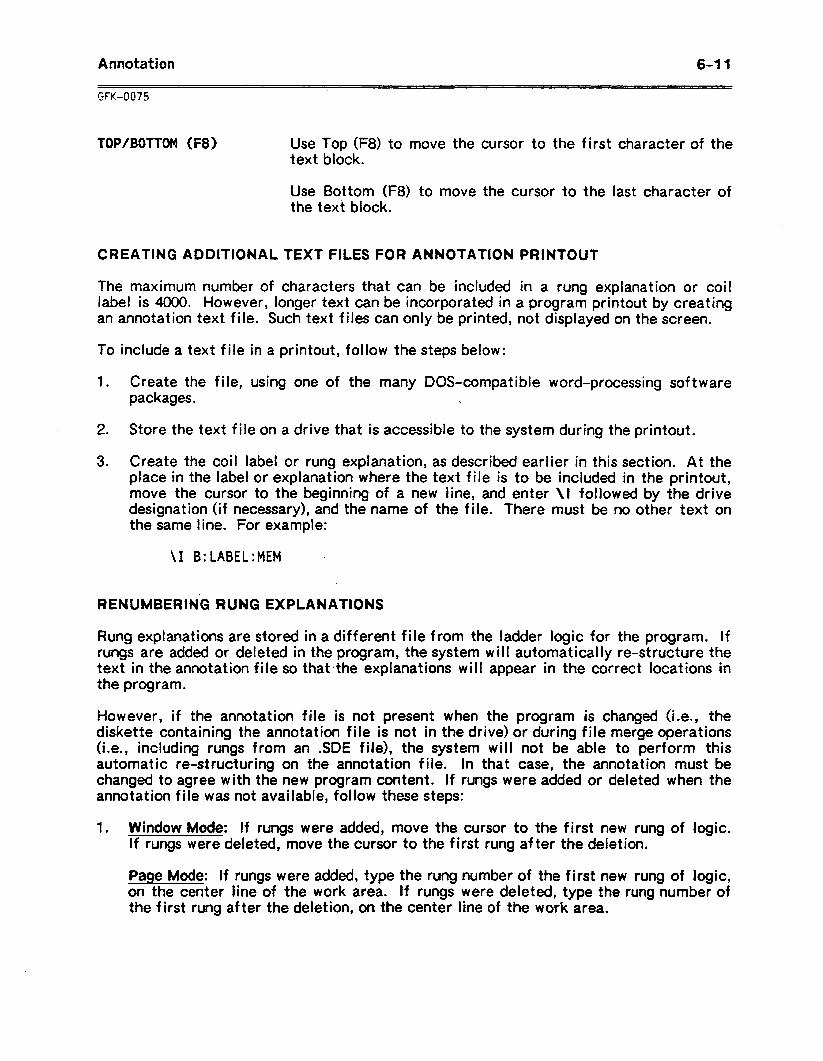
Annotation 6-l 1
GFK-0075
TOP/BOTTOM (F8) Use Top (F8) to move the cursor to the first character of the text block.
Use Bottom (F8) to move the cursor to the last character of the text block.
CREATING ADDITIONAL TEXT FILES FOR ANNOTATION PRINTOUT
The maximum number of characters that can be included in a rung explanation or coil label is 4000. However, longer text can be incorporated in a program printout by creating an annotation text file. Such text files can only be printed, not displayed on the screen.
To include a text file in a printout, follow the steps below:
1 . Create the file, using one of the many DOS-compatible word-processing software packages. .
2. Store the text file on a drive that is accessible to the system during the printout.
3 . Create the coil label or rung explanation, as described earlier in this section. At the place in the label or explanation where the text file is to be included in the printout, move the cursor to the beginning of a new line, and enter \I followed by the drive designation (if necessary), and the name of the file. There must be no other text on the same line. For example:
\I 9: LABEL:MEM .
RENUMBERING RUNG EXPLANATIONS
Rung explanations are stored in a different file from the ladder logic for the program. If rungs are added or deleted in the program, the system will automatically re-structure the text in the annotation file so that the explanations will appear in the correct locat ions in the program.
However, if the annotation file is not present when the program is changed (i.e., the diskette containing the annotation file is not in the drive) or during file merge operations (i.e., including rungs from an .SDE file), the system will not be able to perform this automatic te-structuring on the annotation file. In that case, the annotation must be changed to agree with the new program content. If rungs were added or deleted when the annotation file was not available, follow these steps:
1 . Window Mode: If rungs were added, move the cursor to the first new rung of logic. if rungs were deleted, move the cursor to the first rung after the deletion.
Page Mode: If rungs were added, type the rung number of the first new rung of logic, on the center line of the work area. If rungs were deleted, type the rung number of the first rung after the deletion, on the center line of the work area.
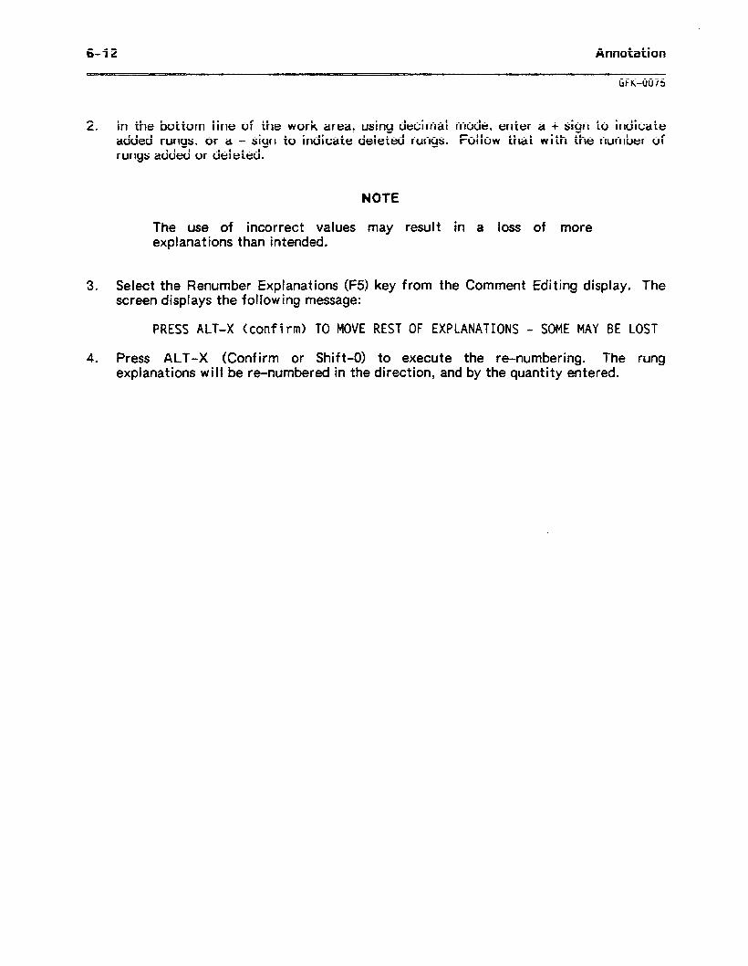
6-f 2 Annotation
UK-0075
2 . In the bottom line of the work area, using decimal mode, enter a + sign to indicate added rungs, or a - sign to indicate deleted rungs. Follow that with the number of rungs added or deleted.
NOTE
The use of incorrect values may result in a loss of more explanations than intended.
3 . Select the Renumber Explanations (F5) key from the Comment Editing display. The screen displays the following message:
PRESS ALT-X (confirm) TO MOVE REST OF EXPLANATIONS - SOME MAY BE LOST
4 . Press ALT-X (Confirm or Shift-O) to execute the re-numbering. The rung explanations will be te-numbered in the direction, and by the quantity entered.
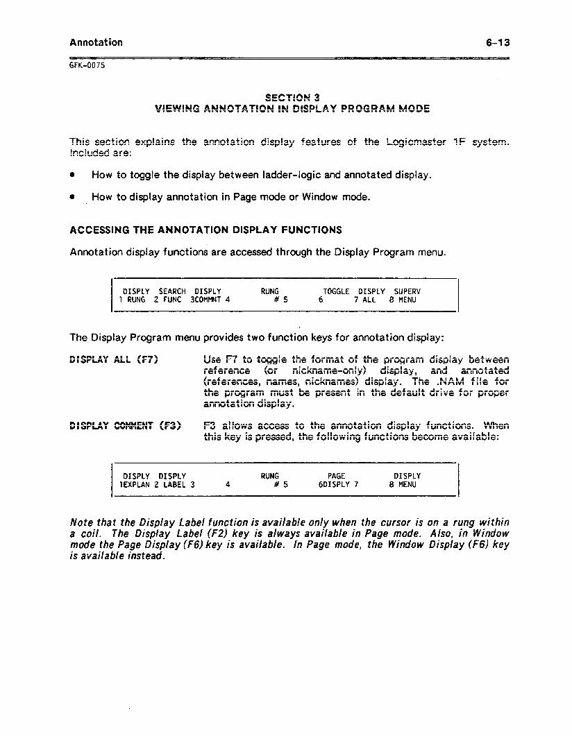
Annotation 6-l 3
GFK-0075
SECTION 3 VIEWING ANNOTATION IN DISPLAY PROGRAM MODE
This section explains the annotation display features of the Logicmaster 1F system. Included are:
0 How to toggle the display between ladder-logic and annotated display.
I) How to display annotation in Page mode or Window mode.
ACCESSING THE ANNOTATION DISPLAY FUNCTIONS
Annotation display functions are accessed through the Display Program menu.
DISPLY SEARCH DISPLY RUNG TOGGLE DISPLY SUPERV 1 RUNG 2 FUNC 3COMMNT 4 #5 6 7 ALL 8 MENU
The Display Program menu provides two function keys for annotation display:
DISPLAY ALL (F7) Use F7 to toggle the format of the program display between reference (or nickname-only) display, and annotated (references, names, nicknames) display. The .NAM file for the program must be present in the default drive for proper annotation display.
DISPLAY COMMENT (F3) F3 allows access to the annotation display functions. When this key is pressed, the following functions become available:
DISPLY DISPLY RUNG PAGE DISPLY 1EXPLAN 2 LABEL 3 4 #5 6DISPLY 7 8 MENU
Note that the Display Label function is available only when the cursor is on a rung within a coil. The Display Label (F2) key is always available in Page mode. Also, in Window mode the Page Display (F6) key is available. In Page mode, the Window Display (f6) key is available instead.
6-l 4 Annotation
GFK-0075
DISPLAY COMMENT FUNCTIONS
D I SPLAY EXPLANAT I ON (Fl ) Use Fl to view rung explanations.
If the Window Display function has been selected and the Window mode is active, then Fl will display the rung explanation of the rung where the cursor is located. The rung explanation appears in a reverse-video window that is seven lines deep and 74 characters wide. If there is additional text, use the cursor to scroll the text in the window.
If the Page Display function has been selected and Page mode is active, then Fl wi II display the rung explanation of the rung number entered in the bottom line of the work area. The rung explanation appears in a reverse-video window that is 21 lines deep and 74 characters wide. If there is additional text, move the cursor to scroll the text in the window.
DISPLAY LABEL (F2)
PAGE/WINDOW DISPLAY (F6)
Use F2 to display coil labels.
If the Window Display function has been selected and Window mode is active, then F2 will display the coil label of the coil on the rung where the cursor is located. The coil label appears in a reverse-video window that is seven lines deep and 46 characters wide. If there is additional text, use the cursor to scroll the text in the window.
If the .Page Display function has been selected and Page mode is active, then F2 will display the coil label of the coil reference entered in the center line of the work area, or the nickname of the coil reference entered on the top line of the work area. The coil label appears in a reverse-video window that is 21 lines deep and 46 characters wide. If there is additional text, use the cursor to scroll the text in the window.
Use F6 to toggle the display between Page Display and Window Display mode.
Annotation 6-l 5
GFK-0075
This ; section describes:
The basic steps followed to print annotation. The printout formats. How to print annotation in foreground mode, or from a print file. How to change the title on a printout. HOW to place borders around comments in printouts.
4nnotation can be printed with the printing is provided in chapter 8.
SECTION 4 NG ANNOTATION
adder program, or separately. information on
SETTING UP THE PRINTER
1 . if the printer has already been set up and the printout parameters specified, go directly to step 2. Otherwise, set up the printer (this is only required when using a printer for the first time).
A . If it is a parallel printer, attach it to port 3. Turn the printer on, and place it in On-Line mode. Continue at step lc.
B . If it is a serial printer, set the DIP switches and jumpers on the printer, as instructed in the manual for the printer. Attach the printer to serial port 1.
C . From the Supervisor menu, select Utility Functions (F8). Enter parameters for port A which correspond to those set up for the printer. Press Fl (SET UP PORT) to implement the printer parameters at the port.
D . Return to the Supervisor menu, and select Print Functions (F5). If no file name is active, enter the file name of the annotation to be printed, on the top line of the work area.
E . Def he the printer parameters. In the Print menu, press F5 (DEFINE PRINTR). The default printer parameters can be changed, as described in chapter 8.
2 . in the Print menu, press F6 (DEFINE OUTPUT) to determine the content of the printout. Here, you can select the program and annotation feature to be printed.
3. To print the annotation in foreground mode, press Fl (PRINT OUT) from the Print enenu. This command can either send the output to a printer directly, or store it as a xint file for printing later in background mode. Specify the port to receive the xintout or file. If the file ‘is being saved for later printing, give it a file name. Dress CTRL-E (Enter) to start the printout.
To print the annotation in background mode, press F2 (PRINT PROG). Specify the printer port and the source drive for the file. Enter the program name. Press CTRL-E (Enter) to start the printout.
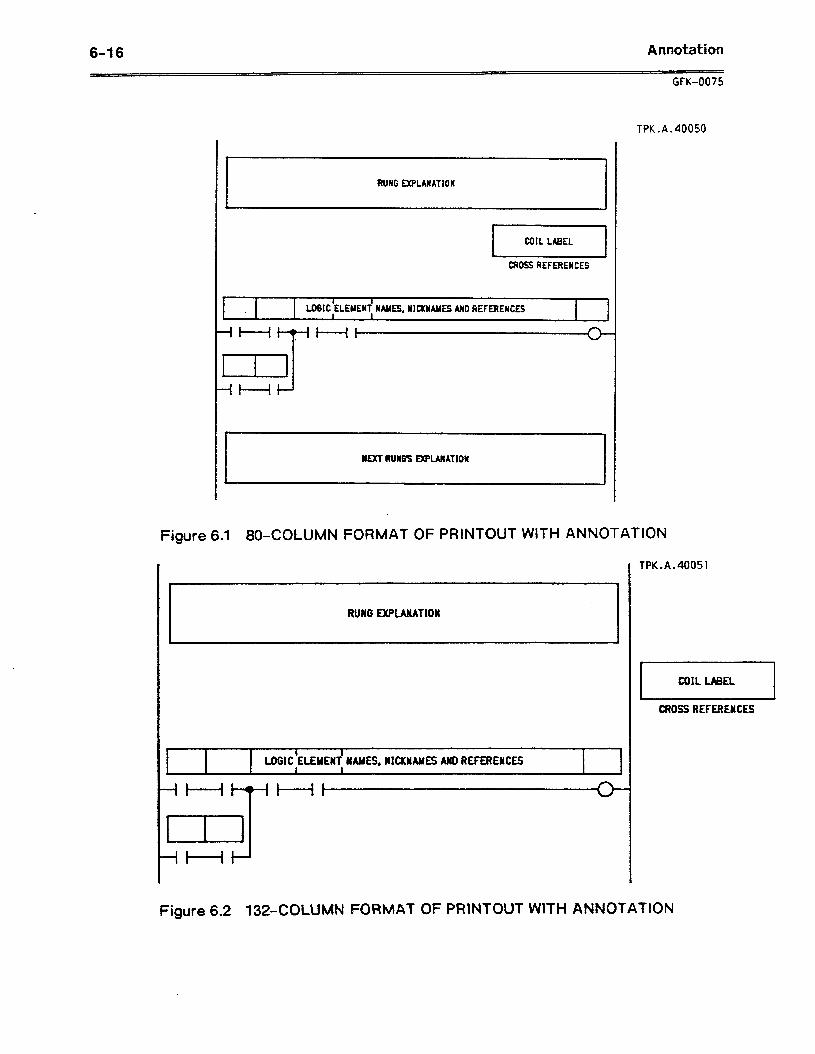
6-l 6 Annotation
t?UWG EXPLANATION
1
I COIL LABEL I
CROSS REFERENCES -
I I 1
LO6IC ELEMENT NAMES, NICKNAMES AND REFERENCES 6 \
-iHWHt
=J .
-iH
I#f RUN6S EXPLANATION
GFK-0075
TPK.A.40050
Figure 6.1 80.COLUMN FORMAT OF PRINTOUT WITH ANNOTATION
T
RUNG ExPuNAT10N
t 1 I l
LOGIC ELEYENT IAMES, NICKNAMES MD REFERENCES . 4
-It----i T’ I t c
.
-iH 3
TPK.A.40051
1 COIL LABEL 1
CROSS REFERENCES
Figure 6.2 132.COLUMN RXtMAT OF PRINTOUT WITH ANNOTATION
Annotation
GFK-0075
6-l 7
CHANGING THE TITLE ON THE PRINTOUT
When the printer output is defined, a title and subtitle for the printout are created. This title and subtitle can be changed before any rung explanation in the program. Each time a new title and subtitle are encountered during a printout of the program, the printer begins a new page. The new title/subtitle are displayed at the top of the page, before the Rung Explanation, and will continue to be displayed until changed by another rung explanation.
Follow the steps below to change the title and/or subtitle for the printout pages.
1 . At the beginning of the rung explanation, enter the characters \T for a new title or \S for a new subtitle.
2 . Type up to 60 characters for the title or subtitle, on the same line as the \T or \S.
3 . Continue the text of the rung explanation on the next line.
PLACING BORDERS AROUND COMMENTS IN PRINTOUTS
To make coil labels and rung explanations stand out in program printouts, borders can be printed around them. The system will automatically create a border of the correct size. To place a border around a label or explanation, follow the instructions below:
1 . Create the coil label or rung explanation, as described in this section.
2 l At the beginning of a line by itself, enter \B followed by two ASCII characters to make up an outer and inner border. The two ASCII characters must be the next two characters after the B. Any spaces in these two positions wibecome part of the border. For example,
\B* (space)
This would create a border of asterisks around the outside of the comment. A blank is usually specified as the inner (second) character, to provide space between the text and the border.
The \T, \S, and \B can be entered on any of the first three lines of the rung explanation, in any order. For example:
For
Borders
\S New subtitle \B * Border \T * New title
coil labels, the \B can be any of the first three lines of the text.
are used only in printouts; they are not displayed on the screen.

Display Reference Tables 7-l
GFK4375
CHAPTER 7 DISPLAY REFERENCE TABLES
The Display Reference Tables function is used to display the status of any group of references. These may be discrete references or registers.
The Display Reference Tables function can be selected from the Supervisor menu or another screen on which it is active. If a CPU is connected and the current system status is on-line, the information shown comes from the CPU. Otherwise, it comes from the programming system’s memory.
This chapter explains how to enter, use, and exit the Display Reference Tables function. Refer to the appropriate sections.
Section 1. Using the Display Reference Tables Function: Read section 1 for general information about the Display Reference Tables function.
Section 2. Displayincr Discrete References: To disPlav the l/O reference table, internal coils table, shift registers table, and timer/counters s&us table, refer to the in&r in section 2.
Section 3. Displaying Data Register Contents: To display the Data Register tabl to the instruct ions in section 3.
Duct ions
e, refer
Section 4. Displaying Accumulate Register Contents: To display the Timer/Counter Accumulate table, refer to the instructions in section 4.
Section 5. Making On-Line Changes: Section 5 explains how to make on-line changes to discrete and register values.
7-2 Display Reference Tables
GFK-0075
SECTION 1 USING THE DISPLAY REFERENCE TABLES FUNCTION
This section consists of general instructions for using the Display Reference Tables function. It explains:
How to enter and exit the function.
l HOW to display the reference table you want, from the Supervisor menu.
l HOW to move within a table, and from one reference table to another.
0 How to return to the ladder logic display from the reference tables.
HOW TO DISPLAY THE REFERENCE TABLES
To display the reference tables values for a program, follow the steps below:
L 1 . in the Supervisor menu, select the reference table to be displayed. Do that in one of the following ways:
A . If you make no entry in the work area, the last table displayed is automatically selected. If no table has been displayed, then the discrete table is selected and the cursor will be on l/O point number 0.
B . Enter a reference, reference type, or nickname in the work area. If only the type of reference is shown in the work area, the first reference of that type is displayed.
2. Select Display Reference Tables (F3) from the Supervisor menu. The reference title and associated table are displayed.
MOVING WITHIN A REFERENCE TABLE
lf there is a reference table on the display and you want to move to another reference address within the same table:
1 . Enter the nickname or reference address into the work area.
2 . Press CTRL-E or the Enter key. The cursor will move on the current screen to the reference. IC that reference is not on the current table, then an error message will be displayed.
Display Reference Tables 7-3
GFK-0G75
MOVING FROM ONE REFERENCE TABLE TO ANOTHER
If there is a reference table on the display and you want to go direct1 table:
1 . Press the appropriate hard key and enter the reference address or ni work area.
2 . Press F8 (DISPLY REF TB).
y to a different
ckname into the
RETURNING TO THE SUPERVISOR MENU
Press the Supervisor key when you want to return to the Supervisor menu from one of the reference tables displays.
You can re-enter the tables without specifying a table. The Logicmaster 1F system will return to the last table that was displayed.
RETURNING TO THE LADDER DIAGRAM DISPLAY
To return to the ladder diagram display from one of the reference tables displays:
1 .
2 .
The
Press the Supervisor key to display the Supervisor menu. .
Select Display Program (Fl).
ladder diagram is displayed, at its last viewing position.
OFF-LINE DISPLAY OF REFERENCE TABLES
When the Logicmaster 1F system is in the Off-Line mode, the reference table values displayed are retrieved from the programmer (RAM) memory. In this mode, data register values and timer/counter accumulate register values can be entered. Entering discrete table values or toggling of l/O is not permitted in the Off-Line mode.
ON-LINE DISPLAY OF REFERENCE TABLES
When the Logicmaster 1F system is in the On-Line or Monitor mode, the reference tables displayed are retrieved from the CPU.
CPU STOPPED The discrete tables display will be blank.
CPU RUN All tables are retrieved from the CPU and displayed..
The programs in the Logicmaster 1F system and the CPU do not need to be equal to display reference tables.
7-4 Display Reference Tables
GFK-0075
SECTION 2 DISPLAYING DISCRETE REFERENCES
This section explains how to display one of the discrete reference tables.
DISPLAYING A TABLE OF DISCRETE REFERENCES
The discrete display screens show status tables of each of the discrete reference types (I/O, internal coils, shift registers, timers and counters). To display the discrete reference table, follow the instructions below:
1 . From the Supervisor menu, 01 enter a reference address from
from within the Display Reference Tables function, 000 to 777 in the reference field of the work area.
The four categories of discrete ref efences are:
Input/Output Internal Coils Shift Registers Timer/Counters
You can also display
ooo-077,077.157, 700-777 160-377 400-577
Up Status 600-677
each table by entering a nickname instead of a reference address. When the table is displayed, the cursor will fall on the address in the table for the nickname entered in the work area.
2. Select Display Reference Table (F3) from the Supervisor menu.
If you press F3 in the Supervisor menu, or press F8 (DISPLY REF TB) from within the Reference Tables function, and the work area is either blank or contains an invalid reference, the reference display that was last shown before exiting the Display References function will be shown. If this function has not been accessed since the Logicmaster 1F system was powered up or reset, the Display References function will default to the display containing discrete status.
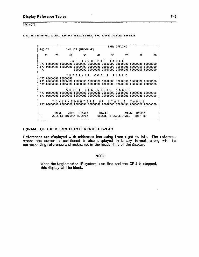
Display Reference Tables 7-S
I/O, INTERNAL COIL, SHIFT REGISTER, T/C UP STATUS TABLE
L/M: OFFLINE POINW I/O 137 (NICKNAME)
77 70 60 50 40 30 20 10 00
INPUT/OUTPUT TABLE 777 00000000 00000000 00000000 00000000 00000000 00000000 00000000 00000000 077 00000000 00000000 00000000 00000000 00000000 00000000 00000000 00000000 177 00000000 00000000 00000000 00000000 00000000 00000000
INTERNAL COILS TABLE 177 00000000 00000000 277 00000000 00000000 00000000 00000000 00000000 00000000 00000000 00000000 377 00000000 00000000 00000000 00000000 00000000 00000000 00000000 00000000
SHIFT REGISTERS TABLE 477 00000000 00000000 00000000 00000000 00000000 00000000 00000000 00000000 577 00000000 00000000 00000000 00000000 00000000 00000000 00000000 00000000
TIMER/COUNTERS UP STATUS TABLE 677 00000000 00000000 00000000 00000000 00000000 00000000 00000000 00000000
BYTE WORD BINARY TOGGLE CHANGE OISPLY 1 2DISPLY 3DISPLY 4DISPLY SENABL 6TOGGLE 7 ALL 8REF TB
FORMAT OF THE DISCRETE REFERENCE DISPLAY
References are displayed with addresses increasing from right to left. The reference where the cursor is positioned is also displayed in binary forma-t, along with its corresponding reference and nickname, in the header line of the display.
NOTE
When the Logicmaster 1F system is on-line and the CPU is stopped, this display will be blank.
7-6 Display Reference Tables
GFK-0075
DISCRETE REFERENCE TABLES FUNCTION KEYS
The bottom of the screen displays the function key assignments:
BYTE DISPLAY (F2) Press F2 to display the value(s) in byte bcdhex format.
WORD D I SPLAY (F3) Press F3 to display the value(s) in word bcdhex format.
BINARY DISPLAY (F4) Press F4 to display discrete value(s) in binary code.
TOGGLE ENABLE (F5) Press F5 to enable the Toggle function. This function is only available in On-Line mode.
TOGGLE (F6)
CHANGE ALL (F7)
DISPLAY REFERENCE TABLE (F8)
Press F6 to change the state (on/off) of the reference point that is currently highlighted by the cursor. This function key is only displayed when toggling is enabled.
Press F7 to change the entire display to the specified format.
Press F8 to change displays within the Display References function.
RETURNING TO THE SUPERVISOR MENU .
Press the Supervisor key when you want to return to the Supervisor menu from one of the reference tables displays.
RETURNING TO THE LADDER DIAGRAM DISPLAY
To return to the ladder diagram display from one of the reference table displays:
1 .
2 .
The
Press the Supervisor key to display the Supervisor menu.
Select Display Program (Fl).
ladder diagram is displayed, at its last viewing position.
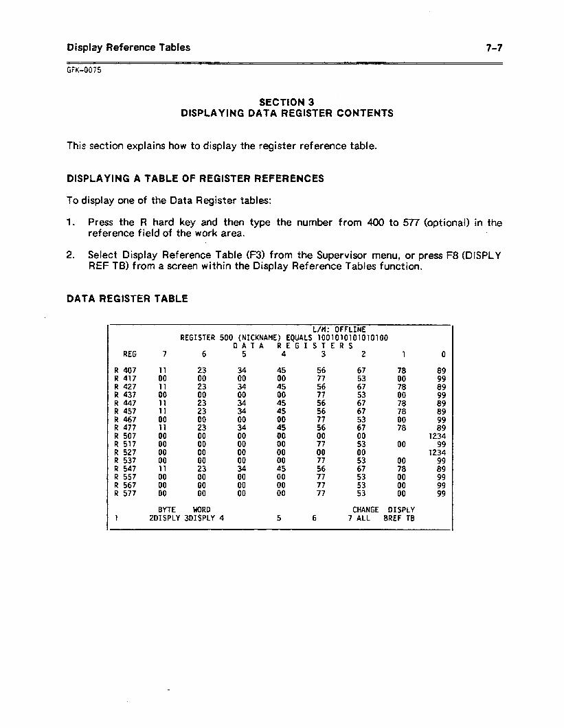
Display Reference Tables 7-7
SECTION 3 DISPLAYING DATA REGISTER CONTENTS
This section explains how to display the register reference table.
DISPLAYING A TABLE OF REGISTER REFERENCES
To display one of the Data Register tables:
1 . Press the R hard key and then type the number from 400 to 577 (optional) in the reference field of the work area.
2. Select Display Reference Table (F3) from the Supervisor menu, or press F8 (DISPLY REF TB) from a screen within the Display Reference Tables function.
DATA REGISTER TABLE
.
L/M: OFFLINE REGISTER 500 (NICKNAME) EQUALS 1001010101010100
DATA REGISTERS REG 7 6 5 4 3 2 1 0
R 407 11 23 34 45 56 67 R 417 00 00 00 00 77 53 R 427 11 23 34 45 56 67 R 437 00 00 00 00 77 53 R 447 11 23 34 45 56 67 R 457 11 23 34 45 56 67 R 467 00 00 00 00 77 53 R 477 11 23 34 45 56 67 R 507 00 00 00 00 00 00 R 517 00 00 00 00 77 53 R 527 00 00 00 00 00 00 R 537 00 00 00 00 77 53 R 547 11 23 34 45 56 67 R 557 00 00 00 00 77 53 R 567 00 00 00 00 77 53 R 577 00 00 00 00 77 53
78 00 78 00 78 78 00 78
00
00 78 00 00 00
1 BYTE WORD CHANGE DISPLY
ZDISPLY 3DISPLY 4 5 6 7 ALL 8REF TB
89 99 89 99 89 89 99 89
1234 99
1234 99 89 99 99 99
7-a Display Reference Tables
GFK-0075
FORMAT OF THE DATA REGISTER REFERENCE DISPLAY
The top line of the register reference display shows the register number at the cursor location (register 500 in the example above). The top line also displays the binary equivalent of the number at the cursor location and the associated nickname.
The left column on the screen indicates the register numbers of the left column of values. The highest number register is on the bottom left.
The default display consists of 16 rows of 8 references each in the byte bcdhex format. The references are displayed with addresses increasing from right to left. The reference where the cursor is positioned is also displayed in binary format, along with its corresponding reference and nickname, in the header line of the display.
The data entered in the work area is moved to the Data Register table memory without any conversion. When the cursor is in the Work Display mode, the valid range is OOOOH to ggg9H. When the cursor is in the Byte Display mode, the valid range is OOH to Q9t-L
REGISTER REFERENCE TABLES FUNCTION KEYS .
The bottom of the screen displays the function key assignments:
BYTE D
WORD D
CHANGE
SPLAY (F2) Press F2 to display the value(s) in byte bcdhex format.
SPLAY (F3) Press F3 to display the value(s) in word bcdhex format.
ALL (F7) Press F7 to change the entire display to the specified format.
DISPLAY REFERENCE TABLE (F8) Press F8 to change displays within the Display References
function.
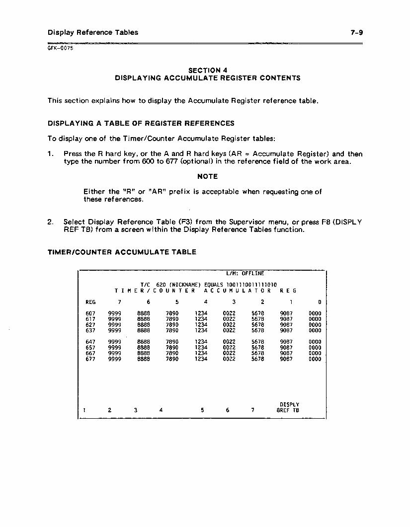
Display Reference Tables 7-9
GFGOC75
SECTION 4 DISPLAYING ACCUMULATE REGISTER CONTENTS
This section explains how to display the Accumulate Register reference table.
DISPLAYING A TABLE OF REGISTER REFERENCES
To display one of the Timer/Counter Accumulate Register tables:
1 . Press the R hard key, or the A and R hard keys (AR = Accumulate Register) and then type the number from 600 to 677 (optional) in the reference field of the work area.
NOTE
Either the “RI’ or “AR”’ prefix is acceptable when requesting one of these references.
2. Select Display Reference Table (F3) from the Supervisor menu, or press F8 (DISPLY REF TB) from a screen within the Display Reference Tables function.
TIMER/COUNTER ACCUMULATE TABLE
REG 7 6 5 4 3 2 1 0
607 9999 8888 7890 1234 0022 5678 9087 0000 617 9999 8888 7890 1234 0022 5678 9087 0000 627 9999 8888 7890 1234 0022 5678 9087 0000 637 9999 8888 7890 1234 0022 5678 9087 0000
647 9999 8888 7890 1234 0022 5678 9087 0000 657 9999 8888 7890 1234 0022 5678 9087 0000 667 9999 8888 7890 1234 0022 5678 9087 0000 677 9999 8888 7890 1234 0022 5678 9087 0000
L/M: OFFLINE
T/C 620 (NICKNAME) EQUALS 1001110011111010 TIMER/COUNTER ACCUMULATOR REG
1 2 3 4 5 6 7 DISPLY
8REF TB
t-1 0 Display Reference Tables
GFK-0075
FORMAT OF THE ACCUMULATE REGISTER REFERENCE DISPLAY
The top line of the Timer/Counter Accumulate Register table shows the register number at the cursor location (timer/counter 620 in the example above). The top line also displays the binary equivalent of the number at the cursor location and the associated nickname.
The table display consists of 8 rows of 8 references, each in the word bcdhex format. The references are displayed with addresses increasing f ram right to left. The reference where the cursor is positioned is also displayed in binary format, along with its corresponding reference and nickname, in the header line of the display.
The data entered in the work area, and on the display, is in decimal format. The valid range is 0000 to 9999. To perform on-line changes, enter the data in the data line of the work area and press CTRL-E or the Enter key.
REGISTER REFERENCE TABLES FUNCTION KEYS
The bottom of the screen displays the function key assignments:
DISPLAY REFERENCE TABLE (F8) Press F8 to change displays within the Display References
function.
Display Reference Tables 7-I 1
SECTION 5 MAKING ON-LINE CHANGES
Sing!e word changes can be made in Display Reference Tables mode. This section explains:
0 The effect of on-line changes.
0 Under what conditions on-line changes may be made.
How to toggle the status of an contact or coil.
How to change register and I/O values.
EFFECT OF ON-LINE CHANGES
As in the Display Program mode, the effect of on-line changes depends upon the current mode (On-Line, Off-Line, or Monitor), whether the program in the CPU is equal or not equal to the program in programmer memory, and whether on-line changes are enabled.
When the system is in On-Line or Monitor mode, status information can be obtained from a connected CPU. This information includes I/O state and register content. To ensure an accurate display, be sure that the Logicmaster 1F system and the CPU programs are equal. If the CPU is locked, data will not be displayed and on-line changes are not permitted.
When the system is connected to a scanning CPU in the On-Line or Monitor mode, displays are updated as the CPU status changes.
When the system is in Off-Line mode, status is always obtained from internal memory. In the Off-Line mode, power flow is shown with numerical values from internal memory.
7-l 2 Display Reference Tables
GFK-0075
MAKING ON-LINE CHANGES
J WARNING [
Exclusive single bit on-line changes of discrete l/O are not supported in either the Series One (Model E) Data Communications Unit of the Series One Plus Data Communications Unit. The toggling function is accomplished by (1) reading a byte wide I/O group from the CPU containing the I/O point to be toggled, (2) setting the I/O point to be toggled, and (3) writing the entire byte wide I/O group back to the CPU memory.
If the CPU changed the status of any I/O points in that group during the read-set-write cycle for I/O toggling, the new status may be overwritten. Because this could produce unexpected and potentially hazardous results, caution is necessary when toggling discrete I/O. Toggling I/O must be performed when programmer memory is cleared to avoid any unexpected or hazardous results.
On-line changes must be enabled in the Communications Setup menu. if they are not enabled, the On-Line Change function key assignment will not be available.
Occasionally, with all types of on-line changes (bit, byte, or word), errors may occur because the system does not verify the change until a later sweep. If an error has occurred, the system cannot try the change again.
Forcing the Status of a Reference
When toggling is enabled in the Display Discrete References function, the Toggle Reference (F6) function key is used to toggle the status of a reference between on and off. The new status is retained until changed by some other function, such as rung solution or I/O servicing. This usually occurs within one scan.
To toggle a reference:
1 . With the table displayed on the screen, enable toggling by pressing the Toggle Enable (F5) key.
2 . Place the cursor on the reference to be forced.
3 . Press F6 to change that reference to its opposite state. All logic elements in the program that use the reference will reflect the new status.
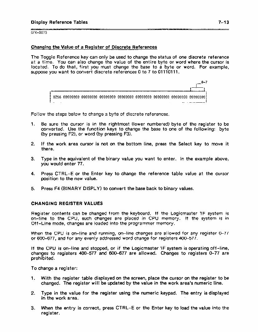
Display Reference Tables
SX-0075
7-l 3
Changing the Value of a Register of Discrete References
The Toggle Reference key can only be used to change the status of one discrete reference at a time. YOU can also change the value of the entire byte or word where the cursor is located. To do that, first you must change the base to a byte or word. For example, suppose you want to convert discrete references 0 to 7 to 01110111.
0256 00000000 00000000 00000000 00000000 00000000 00000000 00000000 00000000
Follow the steps below to change a byte of discrete references.
1 . Be sure the cursor is in the rightmost (lower numbered) byte of the register to be converted. Use the function keys to change the base to one of the following: byte (by pressing FZ), or word (by pressing F3).
2 . if the work area cursor is not on the bottom line, press the Select key to move it there.
3. Type in the equivalent of the binary value you want to enter. In the example above, you would enter 77.
4 . Press CTRL-E or the Enter key to change the reference table value at the cursor position to the new value.
5 . Press F4 (BINARY DISPLY) to convert the base back to binary values.
CHANGING REGISTER VALUES
Register contents can be changed from the keyboard. If the Logicmaster 1F system is on-line to the CPU, such changes are placed in CPU memory. If the system is in Off-Line mode, changes are loaded into the programmer memory.
When the CPU is on-line and running, on-line changes are allowed for any register O-77 or 600-677, and for any evenly addressed word change for registers 400-577.
If the CPU is on-line and stopped, or if the Logicmaster 1F system is operating off-line, changes to registers 400-577 and 600-677 are allowed. Changes to registers O-77 are prohibited.
To change a register:
1 . With the register table displayed on the screen, place the cursor on the register to be changed. The register will be updated by the value in the work area’s numeric line.
2. Type in the value for the register using the numeric keypad. The entry is displayed in the work area.
3 . When the entry is correct, press CTRL-E or the Enter key to load the value into the register.

Print 8-l
GFK-0075
CHAPTER 8 PRINT
The Print function can be used to print copies of ladder logic and annotation. You can print all of a program, or just a part of it. The program currently in programmer memory or the content of the screen can be printed in foreground mode. During a foreground mode print, the system is dedicated to printing and cannot be used for anything else. A program stored as a print file can be printed in background mode, allowing the system to be used for other functions at the same time.
This chapter explains how to use the Print functions. It tells how to enter the characteristics of a new printer, select the content of a print-out, or create or print out a print file. This chapter contains the following sections:
Section 1. The Print Menu: Section 1 explains the Print menu and summarizes the Print function keys.
Section 2. Setting Up the Printer: Section 2 explains how to set up a printer for use with your system.
Section 3. Defining Print-out Content: Section 3 explains how to select the content of a print-out. You can print part or all of the ladder logic, annotation, or cross-reference tables.
Section 4. Printing in Foreground Mode: Section 4 explains how to send a print-out to either a printer or a file.
Section 5. Printing a File in Background Mode: Section 5 explains how to print out a file.
PRINTING A COPY OF THE SCREEN
For quick reference, the Print Screen function can be used to print a copy of the current screen display. Print Screen will print 25 lines of 80 characters.
Before this function can be used, the printer must be set up for printing in background mode, as described in section 2. After this is done, the contents of any screen can be printed out. To execute a screen print, with the screen displayed, press the ALT-P keys at the same time. The print-out stops when the screen has been printed. To stop the print-out sooner, press any other key.
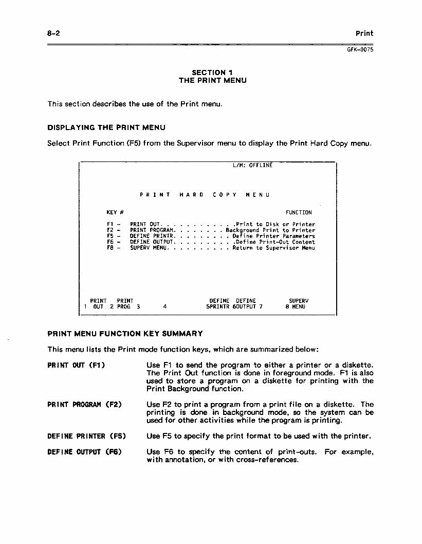
8-2 Print
GFK-0075
SECTION 1 THE PRINT MENU
This section describes the use of the Print menu.
DISPLAYING THE PRINT MENU
Select Print Function (F5) from the Supervisor menu to display the Print Hard Copy menu.
L/M: OFFLINE
PRINT HARD COPY MENU
KEY # FUNCTION
Fl - PRINT OUT. .......... .Print to Disk or Printer F2 - PRINT PROGRAM. ....... Background Print to Printer F5 - DEFINE PRINTR. ........ Define Printer Parameters F6 - DEFINE OUTPUT. ........ .Define Print-Out Content F8 - SUPERV MENU. ......... Return to Supervisor Menu
PRINT PRINT DEFINE DEFINE SUPERV 1 OUT 2 PROG 3 4 5PRINTR 60UTPUT 7 8 MENU
PRINT MENU FUNCTION KEY SUMMARY
This menu lists the Print mode function keys, which are summarized below:
PRINT OUT (Fl) Use Fl to send the program to either a printer or a diskette. The Print Out function is done in foreground mode. Fl is also used to store a program on a diskette for printing with the Print Background function.
PRINT PROGRAM (F2) Use F2 to print a program f ram a print file on a diskette. The printing is done in background mode, so the system can be used for other activities while the program is printing.
DEFINE PRINTER (FS) Use F5 to specify the print format to be used with the printer.
DEFINE OUTPUT fF6) Use F6 to specify the content of print--outs. For example, with annotation, or with cross-references.
Print 8-3
GFK-0075
SECTION 2 SETTING UP THE PRINTER
Follow the instructions in this section before doing any printing. This section explains:
0 How to attach your printer to the system.
0 How to define the printer parameters.
ATTACHING YOUR PRINTER TO THE SYSTEM
Follow the instructions for the type of printer you are using.
Parallel Printer
1 . Attach the printer to a parallel printer port. With a Workmaster computer, use the lower port on the Combination Adapter card.
2. When you are ready to use the printer, turn it on and place it in the On-line mode.
3. To use the Print Menu functions, you must define the printer parameters as explained in this section.
4 . If you expect to use the Print Screen command, set up the printer for printing in background mode:
A . From the Supervisor menu, select Print Functions (F5). Press F2 (PRINT PROG) to set up background printing.
B . Enter the number of the destination port. For the Workmaster computer, this is port 3.
The printer may now be used with the Print Screen command.
8-4 Print
GFK-0075
Serial Printer
1 .
2 .
3 .
4 .
5 .
6 .
Set the DIP switches and jumpers on the printer as instructed in the manual for the printer.
Attach the printer to serial port 1 or 2. With a Workmaster computer, the upper port on the Combination Adapter card is port 1.
From the Supervisor menu, select Utility Functions (F8).
A . In the Utilities menu, press F6 (PORT SET UP). Enter parameters for the port (1 or 2) which correspond to those set up for the printer.
B . Press Fl (SET UP PORT) to store the printer parameters.
When you are ready to use the printer, turn it on and place it in the On-Line mode.
To use the Print Menu functions, you must define the printer parameters, as explained in this section.
If you expect to use the Print Screen command, set up the printer for printing in background mode:
A . From the Supervisor menu, select Print Functions (F5). Press F2 (PRINT PROG) to set up background printing.
.
B . Enter the number of the destination port. For the Workmaster computer, this is port 1 or 2.
NOTE
Do not disconnect the printer cable while printing. When the cable is reconnected, the print-out will be incorrect.
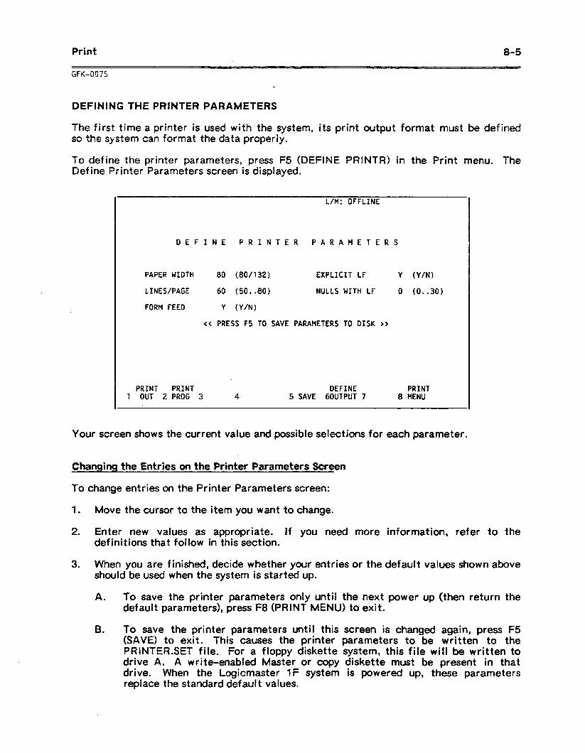
To define the printer parameters, press FS (DEFINE PRINTR) in the Print menu. The Define Printer Parameters screen is displayed.
L/M: OFFLINE
DEFINE PRINTER PARAMETERS
PAPER WIDTH 80 (8O/t32) EXPLICIT LF Y (Y/N)
LINES/PAGE 60 (50..80) NULLS WITH LF 0 (0..30)
FORM FEED Y (Y/N)
<< PRESS f5 TO SAVE PARAMETERS TO DISK >>
PRINT PRINT DEFINE PRINT 1 OUT 2 PROG 3 4. 5 SAVE 60UTPUT 7 8 MENU
GFK4C)75
8-5
DEFINING THE PRINTER PARAMETERS
The first time a printer is used with the system, its print output format must be defined SC the system can format the data properly.
Your screen shows the current value and possible selections for each parameter.
Changing the Entries on the Printer Parameters Screen
To change entries on the Printer Parameters screen:
1 . Move the cursor to the item you want to change.
2 . Enter new values as appropriate. If you need more information, refer to the definitions that follow in this section.
3. When you are finished, decide whether your entries or the default values shown above should be used when the system is started up.
A . To save the printer parameters only until the next power up (then return the default parameters), press F8 (PRINT MENU) to exit.
B . To save the printer parameters until this screen is changed again, press F5 (SAVE) to exit. This causes the printer parameters to be written to the PRlNTER.SET file. For a floppy diskette system, this file will be written to drive A. A write-enabled Master or copy diskette must be present in that drive. When the Logicmaster 1F system is powered up, these parameters replace the standard default values.
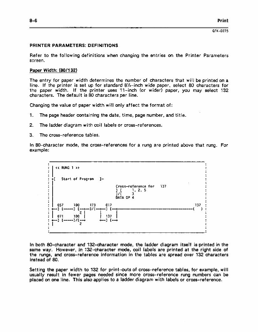
8-6 Print
CFK-0075
PRINTER PARAMETERS: DEFINITIONS
Refer to the following definitions when changing the entries on the Printer Parameters ssreen.
Paper Width: (80/l 32)
The entry for paper width determines the number of characters that will be printed on a line. if the printer is set up for standard 8%inch wide paper, select 80 characters for the paper width. If the printer uses V-inch (or wider) paper, you may select 132 characters. The default is 80 characters per line.
Changing the value of paper width will only affect the format of:
1 . The page header containing the date, time, page number, and title.
2. The ladder diagram with coil labels or cross-references.
3. The cross-reference tables.
In 80.character mode, the cross-references for a rung are printed above that rung. For example:
. .
l .
. << RUNG 1 >> .
. .
. . . .
. . . . : +[ Start of Program J- . . . . . . . Cross-reference for 137 . . . . . 3 1 1, 2, 5 . . . . 10 3 . . . . DATA OP 4 . . . . . . 057 L-1 I-----
100 173 017 137 I +][--+-------------_--------
I
--_--_( ) : . . . . . . 071 :,:q-"/[ I 137 I . . : t-1 [---]I[--+ . . . . I
+-I I4
2 . . . . . . . . . .
In both 80.character and 132.character mode, the ladder diagram itself is printed in the same way. However, in 13%tiaractet mode, coil labels are printed at the right side of the rungs, and cross-reference information in the tables are spread over 132 characters instead of 80.
Setting the paper width to 132 for print-outs of cross-reference tables, for example, will usually result in fewer pages needed since more cross-reference rung numbers can be placed on one line. This also applies to a ladder diagram with labels or cross-reference.
Print 8-7
GFK-0075
Number of Lines per Page: (50..80)
This entry determines the maximum number of lines that will be printed before the system automatically starts a new page. The range of possible values is from 50 through 80 lines per page. The default value is 60 lines per page.
If an associated group of lines will not fit on one page, the system will command the printer to advance to the next page after the number of lines specified by this entry. Note that some printers automatically insert a form feed after printing a certain number of lines (typically, 66). If the printer has this feature, specify a shorter page length to prevent an automatic page eject.
Form Feed: (Y/N)
This item determines whether the system automatically inserts an ASCII form feed character at the end of a page.
1 . This item should be set to Y (yes) if the printer recognizes a form feed.
2. Set this item to N if the printer does not r,ecognize the form feed character. That will cause the system to insert a sequence of carriage returns to advance from the last line printed on one page to the top of the next page. The number of carriage returns output will depend upon the previous parameter, LINES PER PAGE.
Explicit Line Feed: (Y/N)
The line feed character advances the paper to the next line for printing. This item determines whether the system automatically inserts a line feed character each time the printer head returns to the left page margin.
1 . This item should be set to Y (yes) to have the system insert a line feed character after each carriage return character.
2. Set this item to N (no) if the printer automatically advances the paper each time it encounters a carriage return character.
The default for this parameter is Y (yes).
Nulls with Line Feed: (0..30)
This parameter defines the number of null characters (characters that have no effect on the printer) that must be sent to the printer after a carriage return character. Some printers require these null characters to allow the print head sufficient time to return to the left margin after the carriage return. The quantity of null characters the system will automatically output may vary from 0 to 30, with the default value being 0. Most printers now have internal c0ntrok for this fun&on.
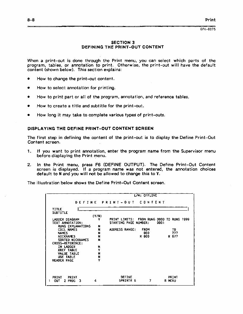
8-8 Print
GFK-0075
SECTION 3 DEFINING THE PRINT-OUT CONTENT
When a print-out is done through the Print menu, you can select which parts of the program, tables, or annotation to print. Otherwise, the print-out will have the default content (shown below). This section explains:
0 How to
0 How to
0 How to
I, How to
change the print-out content.
select annotation for printing.
print part or all of the program, annotation, and reference tables.
create a title and subtitle for the print-out.
0 How long it may take to complete various types of print-outs.
DISPLAYING THE DEFINE PRINT-OUT CONTENT SCREEN .
The first step in defining the content of the print-out is to display the Define Print-Out Content screen.
1 . If you want to print annotation, enter the program name from the Supervisor menu before displaying the Print menu.
2 . In the Print menu, press F6 (DEFINE OUTPUT). The Define Print-Out Content screen is displayed. if a program name was not entered, the annotation choices default to N and you will not be allowed to change this to Y.
The illustration below shows the Define Print-Out Content screen.
DEFINE PRINT-OUT CONTENT
TITLE I I SUBTITLE
(Y/N) LADDER DIAGRAM Y PRINT LIMITS: FROM RUNG 0000 TO RUNG 1999 TEXT ANNOTATION: STARTING PAGE NUMBER: 0001
RUNG EXPLANATIONS N COIL NAMES N ADDRESS RANGE: FROM TO NAMES N 000 777 NICKNAMES N R 000 R 677 SORTED NICKNAMES N
CROSS-REFERENCE: IN LADDER H XREF TABLE Y VklUE TABLE N USE TABLE N
HEADER PAGE Y
PRINT PRINT DEFINE PRINT 1 OUT 2 PROG 3 4 SPRINTR 6 7 8 MENU
Print a-9
WK-0075
CHANGING THE ENTRIES ON THE PRINT-OUT CONTENT SCREEN
To change entries on the Print-Out Contents screen: Y
1 .
2 .
3 .
Move the cursor to the items you want to change.
Type in new entries. if you need more information, refer to the definitions that follow in this section.
To reduce the time needed for a cross-reference print-out, select only the address range actually needed. Setting the system mode to Off-Line (using the mode-select keyswitch, or on the Scratch Pad screen), should also reduce cross-reference print-out time.
When the entries are complete, press F8 (PRINT MENU) to return to the Print menu. If the printer parameters have been established, the content can be printed using the Print Out function.
ONS DEFINE PRINT-OUT CONTENT SCREEN: DEFINIT I
Refer to the following definitions when making entr i
TITLE To print a main title at
es on the Print-Out Contents screen.
the beginning of each page, enter the title here. This title can be changed within a print-out, as explained in chapter 6, by specifying a YTnew title” at the beginning of a rung explanation text block. To enter a title:
SUBTITLE
1 . If the reverse-video banner is not displayed at the top of your screen, press the Up cursor key as needed.
2 . Type in a title of up to 60 characters. To make changes, you can use the Delete key to delete the last character, or the Clear key to delete all the characters at once.
To print a subtitle below the title on each page, enter it here. This is entered like a title, as explained above, except that you must use “\S” to change the subtitle within an explanation.
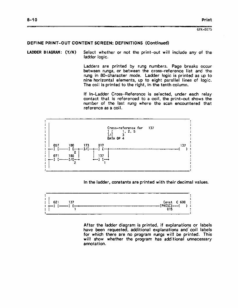
8-l 0 Print
GFK-0075
DEFINE PRINT-OUT CONTENT SCREEN: DEFINITIONS (Continued)
LADDER DIAGRAM: (Y/N) Select whether or not the print-out will include any of the ladder logic.
Ladders are printed by rung numbers. Page breaks occur between rungs, or between the cross-reference list and the rung in 80.character mode. Ladder logic is printed as up to nine horizontal elements, up to eight parallel lines of logic. The coil is printed to the right, in the tenth column.
If In-Ladder Cross-Reference is selected, under each relay contact that is referenced to a coil, the print-out shows the number of the last rung where the scan encountered that reference as a coil.
. . . .
. . . .
. . Cross-reference for 137 . .
. . 1 1 1, 2, 5 . .
. . . 30 3 .
. DATA 09 4 . . .
. . .
. . 057 100 173 017 137 I :+-I[-
I :,:;T"'T:3:-/-
mm- ( ) . . . . . . . . 071 . . :+--][- I&-+ +-I c-+ . . . . . 2 1 . .
I . . .
. . . .
In the ladder, constants are printed with their decimal values.
. .
. .
. . I 021 137 : +-J
I [- 1 t- . . 1
. .
. .
. Const C 600 i
-m- [PRESCI--( ) : 015 . .
. .
After the I have been for which will show annotation
adder diagram is printed, if explanations or labels requested, additional explanations and- coi I labels
there are no program rungs will be printed. This whether the program has additional unnecessary
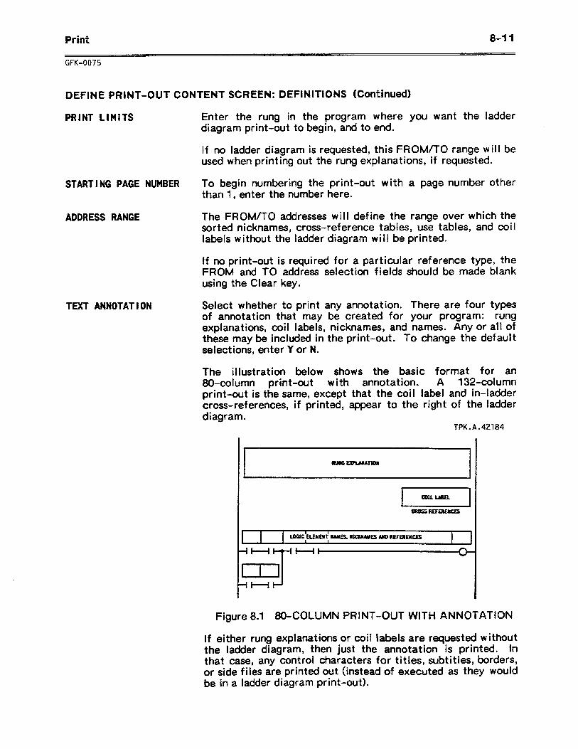
Print 0-I 1
GFK-0075
DEFINE PRINT-OUT CONTENT SCREEN: DEFINITIONS (Continued)
PRINT LIMITS
STARTING PAGE NUMBER To begin numbering the print-out with a page number other than 1, enter the number here.
ADDRESS RANGE The FROM/TO addresses will define the range over which the sorted nicknames, cross-reference tables, use tables, and labels without the ladder diagram will be printed.
Enter the rung in the program where you want the ladder diagram print-out to begin, and to end.
If no ladder diagram is requested, this FROM/TO range will be used when printing out the rung explanations, if requested.
If no print-out is required for a particular reference type, FROM and TO address selection fields should be made bl using the Clear key.
coil
the ank
TEXT ANNOTATION Select whether to print any annotation. There are four types of annotation that may be created for your program: rung explanations, coil labels, nicknames, and names. Any or all of these may be included in the print-out. To change the default selections, enter Y or N.
The illustration below shows the basic format for an 80.column print-out with annotation. A 132.column print-out is the same, except that the coil label and in-ladder cross-references, if printed, appear to the right of the ladder diagram.
TPK.A.42184
I 1 I
LOGIC ELEyWf MAMEsa r:nvEs MD UEFEJEWCES I . -It---$ HI
7-1
Figure 8.1 80-COLUMN PRINT-OUT WITH ANNOTATION
If either rung explanations or coil labels are requested without the ladder diagram, then just the annotation is printed. In that case, any control characters for titles, subtitles, borders, or side files are printed out (instead of executed as they would be in a ladder diagram print-out).
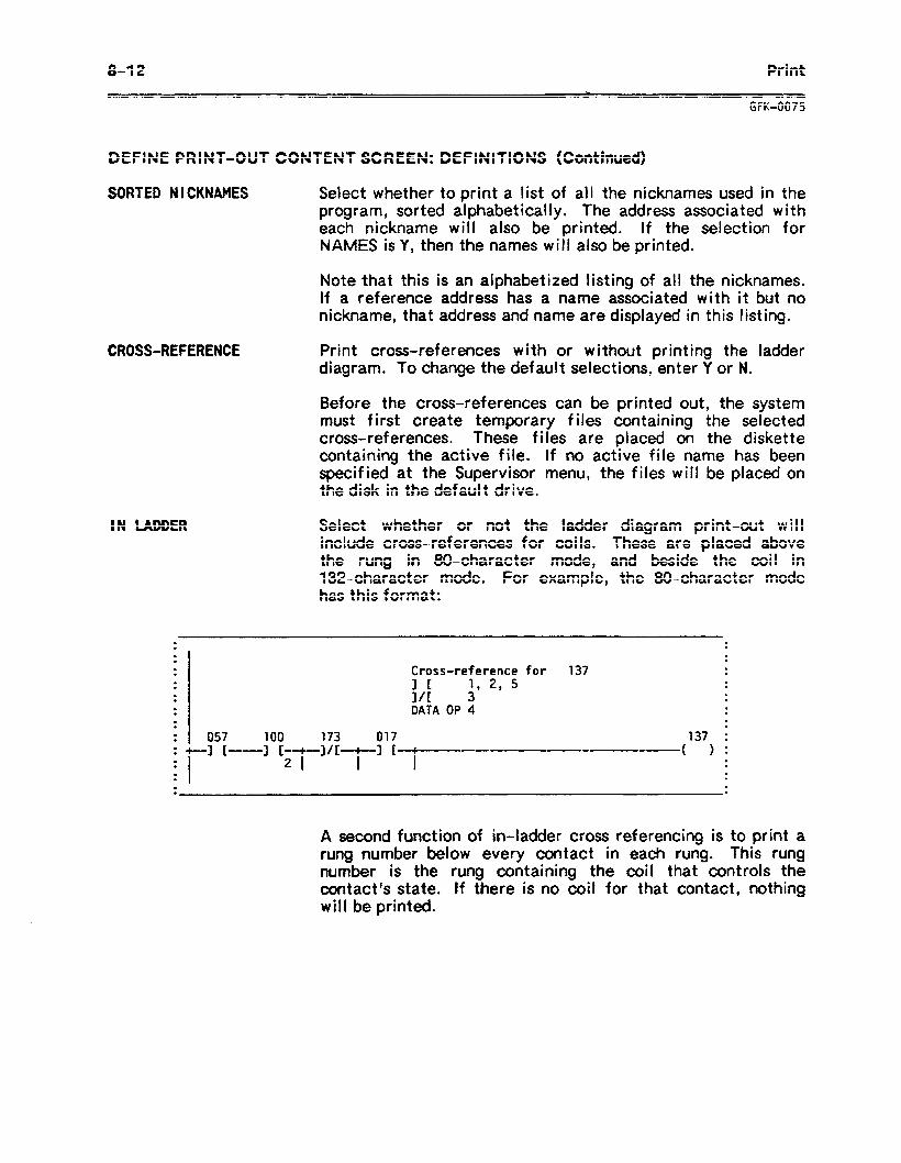
8-12 Print
GFK-0075
DEFINE PRINT-OUT CONTENT SCREEN: DEFINITIONS (Continued)
SORTED NICKNAMES
CROSS-REFERENCE
Select whether to print a list of all the nicknames used in the program, sorted alphabetically. The address associated with each nickname will also be printed. If the selection for NAMES is Y, then the names will also be printed.
Note that this is an alphabetized listing of all the nicknames. If a reference address has a name associated with it but no nickname, that address and name are displayed in this listing.
Print cross-references with or without printing the ladder diagram. To change the default selections, enter Y or N.
Before the cross-references can be printed out, the system must first create temporary files containing the selected cross-references. These files are placed on the diskette containing the active file. If no active file name has been specified at the Supervisor menu, the files will be placed on the disk in the default drive.
Select whether or not the ladder diagram print-out will include cross-references for coils. These are placed above the rung in BO-character mode, and beside the coil in 132~character mode. For example, the BO-character mode has this format:
. . . .
. . . .
. . Cross-reference for 137 . .
. 1 I 1, 2, 5 . . .
. l/C 3 . . .
. . DATA OP 4 . .
. . .
. 057 100 173 017 I +-I [--3 [-+-]/f-+-]
137 I [ -~~-LIIICIIIIIIIIIIIIIII~ ( 1:
.
I 21 I I
. . . . . l . . . . .
A second function of in-ladder cross referencing is to print a rung number below every contact in each rung. This rung number is the rung containing the coil that controls the contact’s state. If there is no coil for that contact, nothing will be printed.
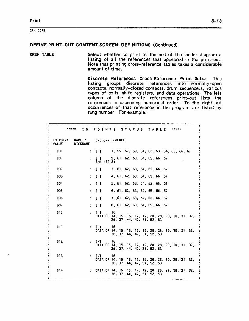
Print 8-l 3
GFK-0075
DEFINE PRINT-OUT CONTENT SCREEN: DEFINITIONS (Continued)
XREF TABLE Select whether to print at the end of the ladder diagram a listing of all the references that appeared in the print-out. Note that printing cross-reference tables takes a considerable amount of time.
Discrete References Cross-Reference Print-Outs: This listing groups discrete references into normally-open contacts, normally-closed contacts, drum sequencers, various types of coils, shift registers, and data operations. The left column of the discrete references print-out lists the references in ascending numerical order. To the right, all occurrences of that reference in the program are listed by rung number. For example:
. .
. .
. .
. .
. .
. .
. .
. .
. .
. .
. .
. .
. .
. .
. .
. .
. .
. .
. .
. .
. .
. .
. .
. .
. .
. .
. .
. .
. .
. .
. .
. .
. .
. .
. .
. .
. .
. .
. .
. .
. .
. .
.
. . *xxx* IO POINTS STATUS TABLE R**X* . .
. .
. . IO POINT NAME / CROSS-REFERENCE . . VALUE NICKNAME . .
.
000 . . 1 c 1, 55, 57, 59, 61, 62, 63, 64, 65, 66, 67 ; . .
001 . . 1 c 2, 61, 62, 63, 64, 65, 66, 67 . . SHF REG 21 . . .
. . 002 . . 1 c 3, 61, 62, 63, 64, 65, 66, 67 . .
. . 003 . . 11 4, 61, 62, 63, 64, 65, 66, 67 . .
. . 004 . . I c 5, 61, 62, 63, 64, 65, 66, 67 . .
. . 005 . . 1 I 6, 61, 62, 63, 64, 65, 66, 67 . .
. . 006 . . 1 [ 7,.67, 62, 63, 64, 65, 66, 67 . .
. . 007 . . 1 I 8, 61, 62, 63, 64, 65, 66, 67 . .
. . 010 . ' 31 16 .
DATA OP 14, 15, 15, 17, 19, 20, 28, 29, 30, 31, 32, ; 36, 37, 44, 47, 51, 52, 53 . .
. . 011 . . 1 t 16 .
DATA OP 14, 15, 15, 17, 19, 20, 28, 29, 30, 31, 32, ; 36, 37, 44, 47, 51, 52, 53 . .
. . 012 . . l/E 16 .
DATA OP 14, 15, 15, 17, 19, 20, 28, 29, 30, 31, 32, ; 36, 37, 44, 47, 51, 52, 53 . .
. . 013 . . 10 16 .
DATA OP 14, 15, 15, 17, 19, 20, 28, 29, 30, 31, 32, ; 36, 37, 44, 47, 51, 52, 53 l .
. 014 : DATA OP 14, 15, 15, 17, 19, 20, 28, 29, 30, 31, 32, ;
36, 37, 44, 47, 51, 52, 53 . . .
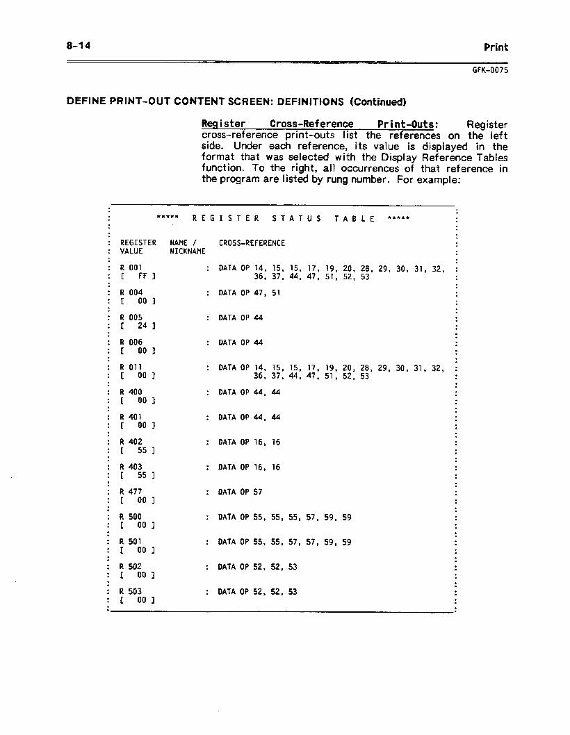
8-14 Print
GFK-0075
DEFINE PRINT-OUT CONTENT SCREEN: DEFINITIONS (Continued)
Register Cross-Reference Print-Outs: Register cross-reference print-outs list the references on the left side. Under each reference, its value is displayed in the format that was selected with the Display Reference Tables function. To the right, all occurrences of that reference in the program are listed by rung number. For example:
. . . . . RXRXX **II** . . REGISTER STATUS TABLE . . .
. . . NAME / CROSS-REFERENCE . . NICKNAME . .
. .
REGISTER VALUE
.
.
. R 001 C FF 1
: DATA OP 14, 15, 15, 17, 19, 20, 28, 29, 30, 31, 32, : 36, 37, 44, 47, 51, 52, 53 . .
.
. . : DATA 09 47, 51 . .
. .
. . : DATA OP 44 . .
. .
. . : DATA OP 44 . .
. .
. : DATA OF' 14, 15, 15, 17, 19, 20, 28, 29, 30, 31, 32, ;
36, 37, 44, 47, 51, 52, 53 . . . .
: DATA OP 44, 44 . . .
R 004 E DO 1 . . R 005 I 24 I
. .
.
. .
. .
. .
. .
. .
. .
. .
. .
R 006 I: 00 1
R 011 I DO 1
R 400 I 00 1 . .
. .
. . : DATAOP44,44
: DATA OP 16, 16
. .
. .
. .
. .
. .
.
R 401 C 00 I . .
. .
. a
.
.
.
.
. .
. .
.
.
.
.
. .
.
.
R 402 1 55 I
: DATA OP 16, 16 R 403 1 55 1
: DATA OP 57 R 477 c 001
. : DATA OP 55, 55, 55, 57, 59, 59 . .
. .
. . : DATA 09 55, 55, 57, 57, 59, 59 . .
. .
. . : DATA OP 52, 52, 53 . .
. .
. . : DATA OP 52, 52, 53 . .
R 500 I 001
. .
. .
. .
. .
. .
. .
. .
. .
. .
. .
. .
.
R 501 1 00 1
R 502 I DDI
R 503 I 001 . .
. . .
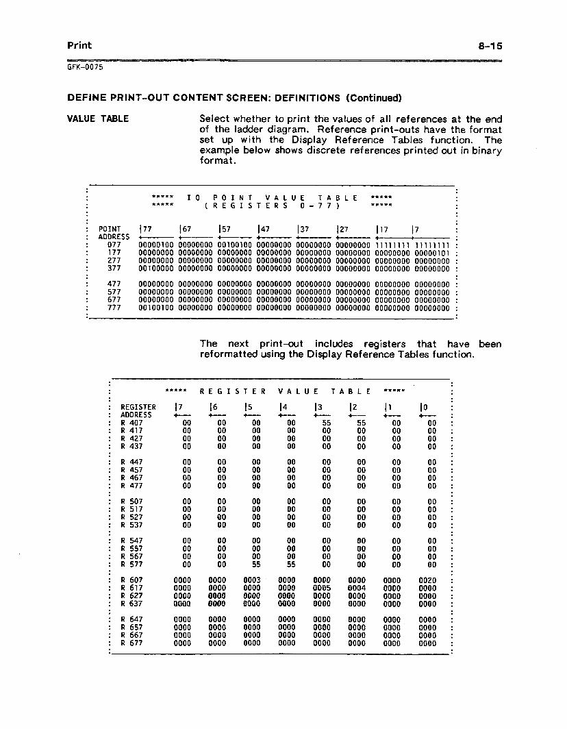
Print 8-15
GFK-0075
DEFINE PRINT-OUT CONTENT SCREEN: DEFINITIONS (Continued)
VALUE TABLE Select whether to print the values of all references at the end of the ladder diagram. Reference print-outs have the format set up with the Display Reference Tables function. The example below shows discrete references printed out in binary format.
. . *Lr**x 10 POINT VALUE TABLE ***** . . ***se (REGISTERS O-77) *x*** . .
.
POINT 177 I67 ADDRESS +--- +m------
077 00000100 00000000 177 00000000 00000000 277 00000000 00000000 377 00100000 00000000
477 00000000 00000000 00000000 00000000 00000000 00000000 577 00000000 00000000 00000000 00000000 00000000 00000000 677 00000000 00000000 00000000 00000000 00000000 00000000 777 00100100 00000000 00000000 00000000 00000000 00000000
.
. .
. RR***
.
.
; REGISTER 17 . . . . . . . l
.
.
.
.
.
.
.
.
.
.
.
.
.
.
.
.
.
.
.
.
.
.
.
.
.
.
.
.
.
.
.
.
.
.
.
.
.
.
.
.
.
.
.
.
.
.
.
.
.
.
.
.
.
ADDRESS R 407 R 417 R 427 R 437
R 447 R 457 R 467 R 477
R 507 R 517 R 527 R 537
R 547 R 557 R 567 R 577
R 607 R 617 R 627 R 637
R 647 R 657 R 667 R 677
+ 00 00 00 00
00 00 00 00
00 00 00 00
00 00 00 00
0000 0000 0000 ooao
0000 0000 0000 0000
The next print-out includes registers that have been reformatted using the Display Reference Tables function.
REGISTER VALUE TABLE
I6 +--- 00 00 00 00
00 00 00 00
00 00 00 00
00 00 00 00
0000 0000 OMRO QUOO
0000 0000 0000 0000
14 +-- 00 00 00 00
00 00 00 00
00 00 00 00
00 00 00 55
0000 0000 OlQCEQ 0000
0000 0000 0000 0000
12 +--- 55 00 00 00
00 00 00 00
00 00 00 00
00 00 00 00
0000 0004 0000 0000
0000 0000 0000 0000
X*X**
I1 +---
00 00 00 00
00 00 00 00
00 00 00 00
00 00 00 00
0000 0000 0000 0000
0000 0000 0000 0000
IO i-- 00 00 00 00
00 00 00 00
00 00 00 00
00 00 00 00
0020 0000 0000 0000
0000 0000 0000 0000
. .
. .
. .
. .
. .
. .
. .
. .
. .
. .
. .
. .
. .
. .
. .
. .
. .
. .
. .
. .
. .
. .
. .
. .
. .
. .
. .
. .
. .
. .
. .
. .
. .
. .
.
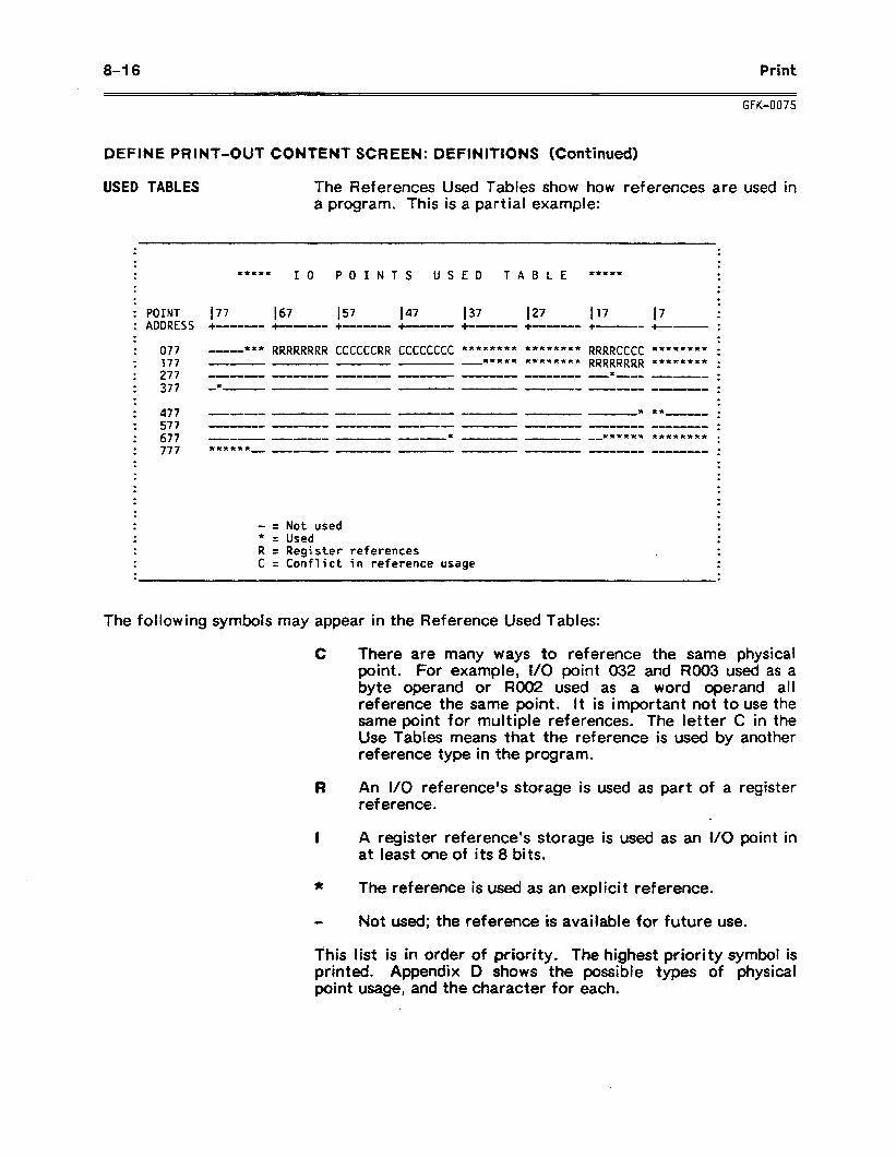
8-l 6 Print
DEFINE PRINT-OUT CONTENT SCREEN: DEFINITIONS (Continued)
USED TABLES The References Used Tables show how references are used in a program. This is a partial example:
. . . .
. . . .
. ***** . I 0 POINTS USED TABLE ***It* . .
. . .
. . . . : POINT 177 167 157 147 137 127 117 17 . . : ADDRESS +----- . . . . . . . . . . . . . . . . . . . . . . . . . . . . . . . . . . . . . . .
+m---0 +-....- +------ +--D- +-9wu--.- +-.-0 . +--0-- .
077 - *It* 177 --- 277 --- 377 -*--
477 --w-m 577 677 --_I 777 **x*x*_
R C
RRRRRRRR CCCCCCRR CCCCCCCC ******** ******** RRRRCCCC ******** ; -I- --- ***** ******** RRRRRRRR *ltx***** :
.
. .
.
.
.
. .
. .
= Not used = Used = Register references = Conflict in reference usage
.
. .
. .
. . .
. .
The following symbols may appear in the Reference Used Tables:
C There are many ways to reference the same physical point. For example, I/O point 032 and RO03 used as a byte operand or RO02 used as a word operand all reference the same point. It is important not to use the same point for multiple references. The letter C in the Use Tables means that the reference is used by another reference type in the program.
R An l/O reference’s storage is used as part of a register reference.
I A register reference’s storage is used as an I/O point in at least one of its 8 bits.
* The reference is used as an explicit reference.
Not used; the reference is available for future use.
This list is in order of priority. The highest priority symbol is printed. Appendix D shows the possible types of physical point usage, and the character for each.
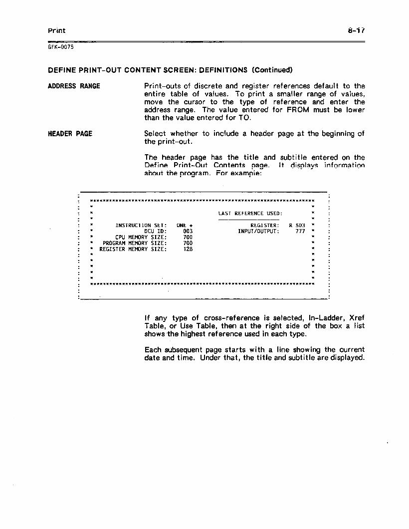
Print 8-l 7
GFK-0075
DEFINE PRINT-OUT CONTENT SCREEN: DEFINITIONS (Continued)
ADDRESS RANGE Print-outs of discrete and register references default to the entire table of values. To print a smaller range of values, move the cursor to the type of reference and enter the address range. The value entered for FROM must be lower than the value entered for TO.
HEADER PAGE
. .
. .
. .
. .
. .
. .
. .
. .
. .
. .
. .
. .
. .
. .
. .
. .
. .
.
Select whether to include a header page at the beginning of the print-out.
The header page has the title and subtitle entered on the Define Print-Out Contents page. It displays information about the program. For example:
.
. * * . . * LAST REFERENCE USED: * . . * -e--rr- * . * INSTRUCTION SET: ONE + - REGISTER: R 503 * I * DCU ID: 003 INPUT/OUTPUT: 777 * : * CPU MEMORY SIZE: 700 * . . * PROGRAM MEMORY SIZE: 700 * . . * REGISTER MEMORY SIZE: 128 * . . * * . . * * . . * * . . * * . * * ****X*~****~*******~*****~***~****%*~*********~~*****~*******~x*******
.
.
.
If any type of cross-reference is selected, In-Ladder, Xref Table, or Use Table, then at the right side of the box a list shows the highest reference used in each type.
Each subsequent page starts with a line showing the current date and time. Under that, the title and subtitle are displayed.
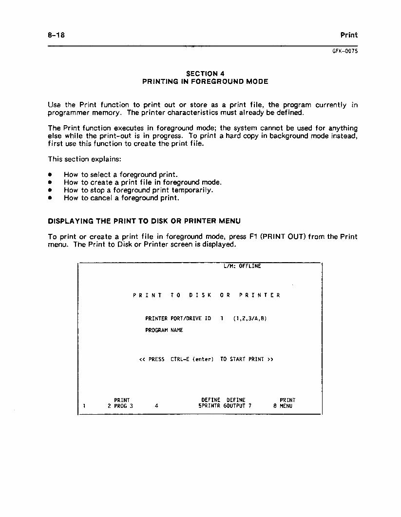
0-10 Print
Use the Print function to programmer memory. The
GFK-0075
SECTION 4 PRINTING IN FOREGROUND MODE
print out or store as a print file, the program currently in printer characteristics must already be defined.
The Print function executes in foreground mode; the system cannot be used for anything else while the print-out is in progress. To print a hard copy in background mode instead, first use this function to create the print file.
This section explains:
l How to select a foreground print. 0 HOW to create a print file in foreground mode. l How to stop a foreground print temporarily. 0 How to cancel a foreground print.
DISPLAYING THE PRINT TO DISK OR PRINTER MENU
To print or create a print file in foreground mode, press Fl (PRINT OUT) from the Print menu. The Print to Disk or Printer screen is displayed.
L/M: OFFLINE
PRINT TO DISK OR PRINTER
PRINTER PORT/DRIVE ID 1 (1,2,3/A,B)
PROGRAM NAME
<C PRESS CTRL-E (enter) TO START PRINT n
1 PRINT DEFINE DEFINE PRINT
2 PROG 3 4 SPRINTR 60UTPUT 7 8 MENU
Print a-1 9
PRINTING IN FOREGROUND MODE
To send the print output directly to printer for immediate printing in foreground mode:
1 . If you are sending the output to a printer, be sure the printer is set up as described in sect ion 2.
2. With the cursor at PRINTER PORT/DRIVE ID, enter the destination for the print-out:
A . Enter the number 3 if the printer is connected to the parallel port.
B . Enter the number 1 or 2 if the printer is connected to a serial port, depending on the number of the serial port. .
3 . Press CTRL-E or the Enter key to start the print-out. The screen continues to display the Print to Disk or Printer screen until the print-out is complete.
CREATING A PRINT FILE
Printing out a complete program can take a considerable amount of time. It is often preferable to first store the information in the form of a print file. A print file can be printed out later in the background mode.
To send the program to a disk drive for later printing in background mode:
1 . For a floppy-diskette system, be sure a write-enabled diskette is in the drive.
2. With the cursor at PRINTER PORT/DRIVE ID, type in the letter destination of the drive to receive the file.
3 . Move the cursor to PROGRAM NAME and enter the name for the print-out.
The first text file created has the file name extension .TXT. If the diskette runs out of space while the file is being stored, the screen prompts for another diskette to be inserted. This second part of the print file has the extension .TXl. For example, PROGRAMITXl. Subsequent portions of the same file will have the file name extension .TX2, and so on.
If the text file is being created on the same disk containing the annotation or temporary cross-reference files, the text file may not be continued beyond one disk. Therefore, if you have a dual-drive system it is reczmended that you always print to a drive that does not contain the annotation files or temporary cross-reference files.
4 . Press CTRL-E or the Enter key to begin creating the file. The screen continues to display the Print to Disk or Printer screen until the file is complete.
8-20 Print
GFK-0075
STOPPING A PRINT-OUT TEMPORARILY
To stop a print-out temporarily (for example, to change the printer ribbon), press F4 (PAUSE PRINT). To resume the print-out at the place it was stopped, press F4 again.
CANCELING A PRINT-OUT
To end a print-out in progress, press F3 (ABORT PRINT). This requires a confirmation by pressing ALT-X (Confirm or Shift-O). When confirmed, it cancels the print-out completely. Aborting a print-out stops the printing only. It does not delete the print files that were created. Print files must be deleted using the Utilities functions.
While waiting for confirmation, the print-out continues. (Confirm or Shift-O) cancels the abort.
Pressing any key except ALT-X
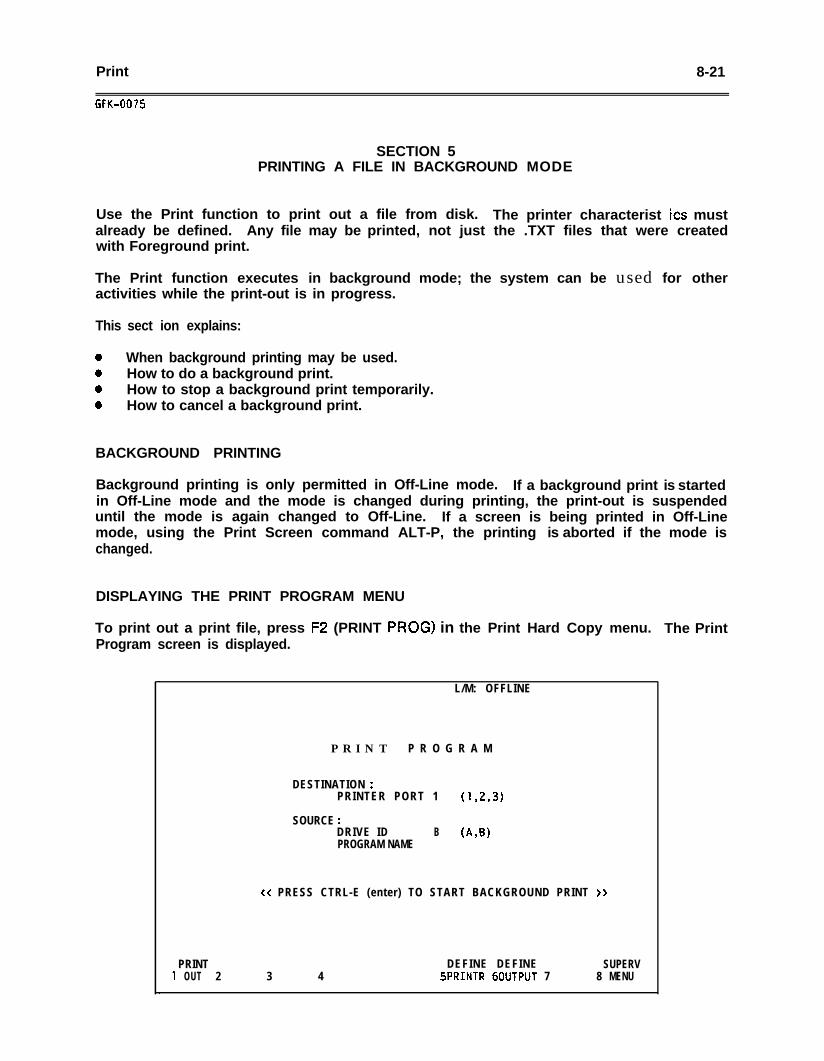
Print 8-21
GFK-0075
SECTION 5PRINTING A FILE IN BACKGROUND MODE
Use the Print function to print out a file from disk. The printer characterist its mustalready be defined. Any file may be printed, not just the .TXT files that were createdwith Foreground print.
The Print function executes in background mode; the system can be used for otheractivities while the print-out is in progress.
This sect ion explains:
0 When background printing may be used.0 How to do a background print.0 How to stop a background print temporarily.0 How to cancel a background print.
BACKGROUND PRINTING
Background printing is only permitted in Off-Line mode. If a background print is startedin Off-Line mode and the mode is changed during printing, the print-out is suspendeduntil the mode is again changed to Off-Line. If a screen is being printed in Off-Linemode, using the Print Screen command ALT-P, the printing is aborted if the mode ischanged.
DISPLAYING THE PRINT PROGRAM MENU
To print out a print file, press FZ (PRINT PROG) in the Print Hard Copy menu.Program screen is displayed.
L/M: OFFLINE
P R I N T P R O G R A M
DESTINATION :PRINTER PORT 1 (1,2,3)
SOURCE :DRIVE ID B (A,B)PROGRAM NAME
cc PRESS CTRL-E (enter) TO START BACKGROUND PRINT >>
PRINT DEFINE DEFINE SUPERV1 OUT 2 3 4 5PRINTR 6OUTPUT 7 8 MENU
The Print
8-22 Print
GFK-0075
ENTER THE DESTINATION AND PROGRAM NAME
To send the print file to a printer port for printing in background mode:
1 . Be sure that the printer is properly connected, and that it is turned on.
2. With the cursor at DESTINATION: PRINTER PORT, enter the destination for theprint-out:
A . Enter the number 3 if the printer is connected to the parallel port.
B . Enter the number 1 or 2 if the printer is connected to a serial port, dependingon the serial port.
3. Move the cursor to DRIVE ID and enter the letter designation of the drive where theprint file is stored.
4 . Move the cursor to PROGRAM NAME and enter the file name and extension. This isusually a .TXT file created with Foreground print. However, any text file may beprinted.
5. Press CTRL-E or the Enter key to start the print-out. The screen displays themessage:
BACKGROUND PRINT IN PROGRESS
6 . Press F8 (PRINT MENU) to return to the Print menu.
STOPPING A PRINT-OUT
To end a print-out in progress, press the Abort Print (F3) function key. This requires aconfirmation by pressing ALT-X (Confirm or Shift-O). When confirmed, it terminates theprint-out completely.
While waiting for confirmation, the print-out continues. If ALT-X (Confirm or Shift-O) isnot pressed, the print-out will continue.
Load/Store/Verify 9- l
GFK-0075
CHAPTER 9LOAD/STOREA/ERtFY
The Load/Store/Verify functions are used to transfer programs and tables between theiiogrammer and the CPU. They are also used to compare the data in the programmerwith that in the CPU.
For information about using the Load/Store/Verify functions, turn to the followingsect ions:
Section 1. The LoadBtoreNerify Menu: Section 1 summarizes the Load/Store/VerifyMenu function keys.
Section 2. Loading a Program into Programmer Memory: Section 2 explains how to loadprogrammer memory with a program and its associated tables. The. program may beloaded from the CPU, or from a disk.
Section 3. Storing Data from Programmer Memory: Section 3 explains how to transfer aprogram and its associated tables from the programmer memory to the CPU, or to a disk.
Section 4. Verifying the Content of Program Data: Section 4 explains how to use theVerify function to compare program data after a Load or Store operation.
Section 5. Clearing Programmer Memory: Section 5 explains how to delete any programand tables currently present in programmer memory.
Be sure that you are using the correct version of the DataCommunications Unit to communicate with the CPU.
CPU
IC610CPUlO4IC61OCPUlOSICdlOCPU106
DCU
IC610CCMlOSB or IC610CCM105CIC610CCMlOSB or laterIC6lOCCMlOSC or 'later
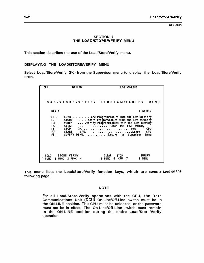
9-2 Load/StoreNerify
GFK-0075
SECTION 1THE LOAD/STOREAIERIFY MENU
This section describes the use of the Load/Store/Verify menu.
DISPLAYING THE LOAD/STORE/VERIFY MENU
Select Load/Store/Verify (F6) from the Supervisor menu to display the Load/Store/Verifymenu.
.CPU : DCU ID: L/M: ONLINE
L O A D / S T O R E / V E R I F Y P R O G R A M / T A B L E S M E N U
KEY # FUNCTION
Fl -F2 -F3 -F5 -F6 -F7 -F8 -
LOAD . . . . . .Load Program/Tables into the L/M M e m o r ySTORE. . . . .VERIFY . . .
Store Program/Tables from the L/M M e m o r y.Verify Program/Tables with the L/M Memory
CLEAR. . . . . . . . . . l . . . . Clear the L/M MemorySTOP CPU . . . . . . . . . . . . . l . . . . . . stop CPUSTART CPU. . . . . . . . . . . . . . . . . . .Start CPUSUPERV MENU. . . . . . . . . .Return to Supervisor Menu
LOAD STORE VERIFY CLEAR STOP SUPERV1 FUNC 2 FUNC 3 FUNC 4 5 FUNC 6 CPU 7 8 MENU
This menu lists the Load/Store/Verify function keys, which are sumA& on thefollowing page.
NOTE
For all Load/Store/Verify operations with the CPU, the DataCommunications Unit (DCU) On-Line/Off-Line switch must be inthe ON-LINE position. The CPU must be unlocked, or the passwordmust not be in effect. The On-Line/Off-Line switch must remainin the ON-LINE position during the entire Load/Store/Verifyoperation.
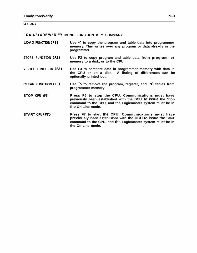
Load/Store/Verify 9-3
GFK-0075
LOAD/STORENERIFY MENU FUNCTION KEY SUMMARY
LOAD FUNCTION (Fl)
STORE FUNCTION (FZ)
IFY FUNCT ION (F3)
CLEAR FUNCTION (FS)
STOP CPU (F6)
START CPU (F7)
Use Fl to copy the program and table data into programmermemory. This writes over any program or data already in theprogrammer.
Use F2 to copy program and table data from programmermemory to a disk, or to the CPU.
Use F3 to compare data in programmer memory with data inthe CPU or on a disk. A listing of differences can beoptionally printed out.
Use F5 to remove the program, register, and I/O tables fromprogrammer memory.
Press F6 to stop the CPU. Communications must havepreviously been established with the DCU to issue the Stopcommand to the CPU, and the Logicmaster system must be inthe On-Line mode.
Press F7 to start the CPU. Communications must havepreviously been established with the DCU to issue the Startcommand to the CPU, and the Logicmaster system must be inthe On-Line mode. .
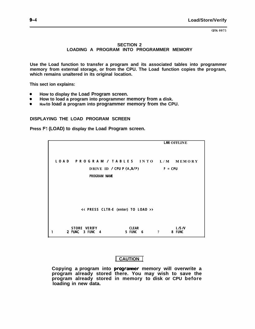
9-4 Load/Store/Verify
GFK-0075
SECTION 2LOADING A PROGRAM INTO PROGRAMMER MEMORY
Use the Load function to transfer a program and its associated tables into programmermemory from external storage, or from the CPU. The Load function copies the program,which remains unaltered in its original location.
This sect ion explains:
0 How to display the Load Program screen.0 How to load a program into programmer memory from a disk.0 HOW to load a program into programmer memory from the CPU.
DISPLAYING THE LOAD PROGRAM SCREEN
Press Ft (LOAD) to display the Load Program screen.
.L/M: OFFLINE
L O A D P R O G R A M / T A B L E S I N T O L / M M E M O R Y
DRIVE ID / CPU P (A,B/P) P = CPU
PROGRAM NAME
<< PRESS CLTR-E (enter) TO LOAD >>
STORE VERIFY CLEAR L / S / V1 2 FUNC 3 FUNC 4 5 FUNC 6 7 8 FUNC
.
1 CAUTION 1
Copying a program into pfogrammer memory will overwrite aprogram already stored there. You may wish to save theprogram already stored in memory to disk or CPU beforeloading in new data.
LoadlStoreNerify 9-5
GFK-0075
LOADING A PROGRAM INTO THE SYSTEM FROM A DISK
To copy the program into the memory of the programmer from a disk:
1 . With the cursor at DRIVE ID/CPU, enter the character that represents the drivewhere the program is stored. Enter the drive or port designation.
2 l Move the cursor to PROGRAM NAME and enter the name of the program.
3 . Press CTRL-E or the Enter key to copy the program into programmer memory. Thescreen displays the word BUSY during the transfer. If the system finds any fault orinconsistency in the data, the Load operation is completed and an error message isdisplayed. After a successful load, the screen displays the message:
LOAD COMPLETE
LOADING A PROGRAM INTO THE SYSTEM FROM A CPU
Use the Load function to copy a program from the CPU into programmer memory.
If the Logicmaster 1F system is in the Off-Line mode, the entire program including theladder logic and tables, is copied into programmer memory. In On-Line mode or Monitormode, only the ladder logic is copied.
1 . With the cursor at DRIVE ID/CPU, enter the letter P, which represents the CPU.
2 . Press CTRL-E or the Enter key to copy the program into memory. The screendisplays the word BUSY during the Load operation. If the system’finds any fault orinconsistency in the data, the Load operation is terminated and an error message isdisplayed. After a successful load, the screen displays the message:
LOAD COMPLETE
If the CPU is in Stop mode prior to loading the user logic from the CPU, a grammarcheck is performed on the CPU user logic. Any errors will be displayed on the screen.
NOTE
Loading a program from the CPU into programmer memory withthe Logicmaster 1 software package may take up to 14 minutes.With the Logicmaster 1 Junior software package, it may take up to19 minutes.
CANCELING THE LOAD FUNCTION
To stop a program transfer in progress, press F4 (ABORT).
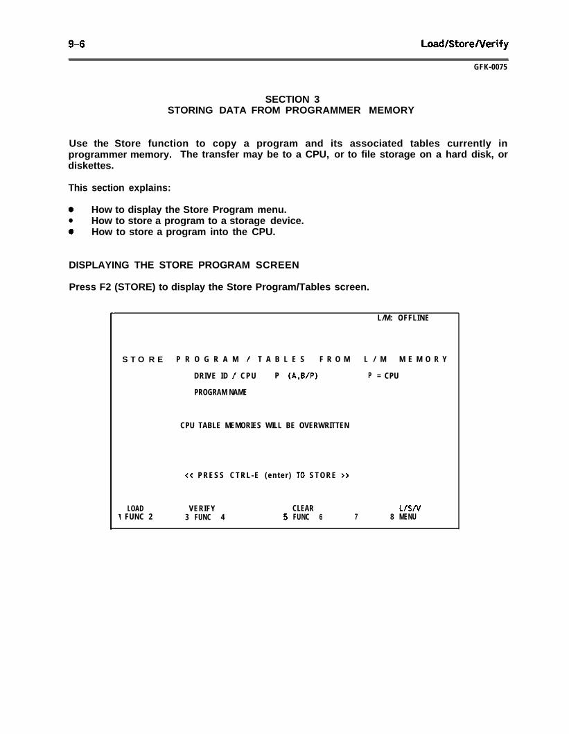
9-6 Load/StoreNerify
GFK-0075
SECTION 3STORING DATA FROM PROGRAMMER MEMORY
Use the Store function to copy a program and its associated tables currently inprogrammer memory. The transfer may be to a CPU, or to file storage on a hard disk, ordiskettes.
This section explains:
0 How to display the Store Program menu.l How to store a program to a storage device.0 How to store a program into the CPU.
DISPLAYING THE STORE PROGRAM SCREEN
Press F2 (STORE) to display the Store Program/Tables screen.
.
S T O R E P R O G R A M / T A B L E S F R O M L / M M E M O R Y
DRIVE ID / CPU P (A,B/P) P = CPU
PROGRAM NAME
CPU TABLE MEMORIES WILL BE OVERWRITTEN
<< PRESS CTRL-E (en te r ) TO STORE >>
LOAD1 FUNC 2
VERIFY CLEAR L/S/V3 FUNC 4 5 FUNC 6 7 8 MENU
L/M: OFFLINE
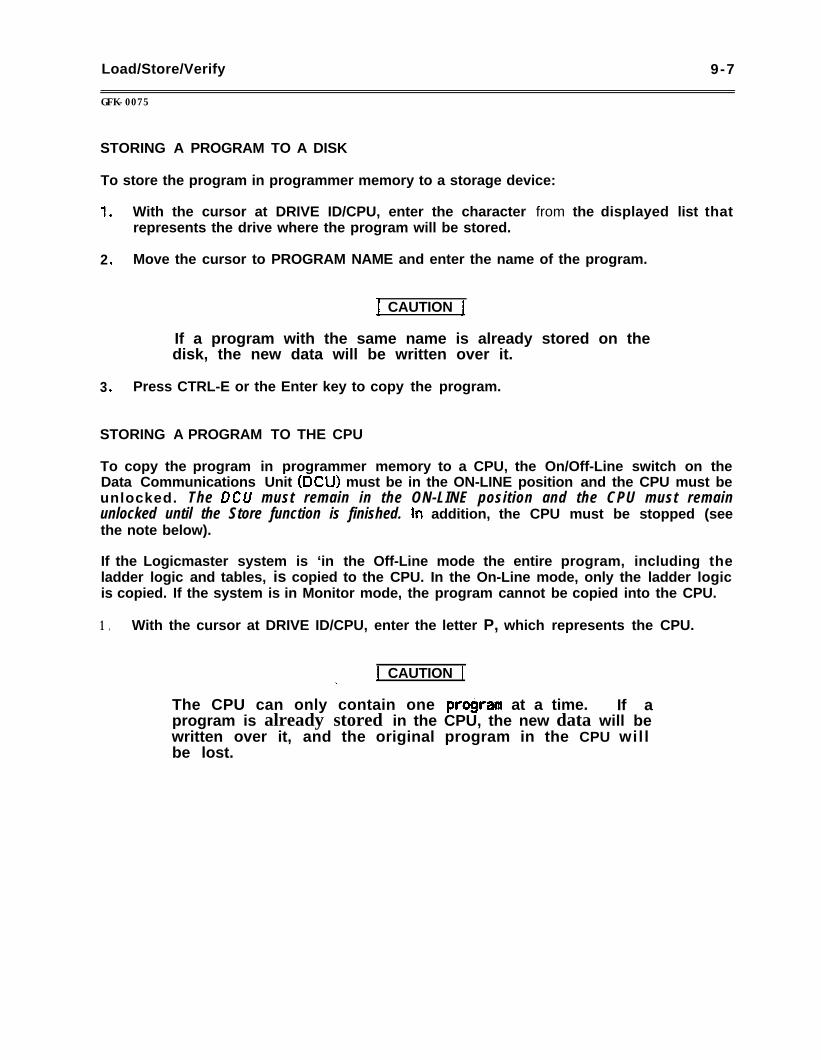
Load/Store/Verify 9-7
GFK-0075
STORING A PROGRAM TO A DISK
To store the program in programmer memory to a storage device:
1 .
2 .
3 .
With the cursor at DRIVE ID/CPU, enter the character from the displayed list thatrepresents the drive where the program will be stored.
Move the cursor to PROGRAM NAME and enter the name of the program.
) CAUTION 1
If a program with the same name is already stored on thedisk, the new data will be written over it.
Press CTRL-E or the Enter key to copy the program.
STORING A PROGRAM TO THE CPU
To copy the program in programmer memory to a CPU, the On/Off-Line switch on theData Communications Unit (DCU) must be in the ON-LINE position and the CPU must beunlocked. The DCU must remain in the ON-LINE position and the CPU must remainunlocked until the Store function is finished. In addition, the CPU must be stopped (seethe note below).
If the Logicmaster system is ‘in the Off-Line mode the entire program, including theladder logic and tables, is copied to the CPU. In the On-Line mode, only the ladder logicis copied. If the system is in Monitor mode, the program cannot be copied into the CPU.
1 . With the cursor at DRIVE ID/CPU, enter the letter P, which represents the CPU.
j CAUTION 1._
The CPU can only contain one program at a time. If aprogram is already stored in the CPU, the new data will bewritten over it, and the original program in the CPU willbe lost.
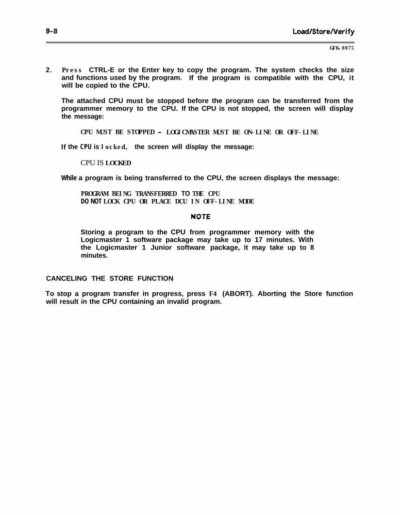
9-8 LoadlStoreNerify
GFK-0075
2 . Press CTRL-E or the Enter key to copy the program. The system checks the sizeand functions used by the program. If the program is compatible with the CPU, itwill be copied to the CPU.
The attached CPU must be stopped before the program can be transferred from theprogrammer memory to the CPU. If the CPU is not stopped, the screen will displaythe message:
CPU MUST BE STOPPED - LOGICMASTER MUST BE ON-LINE OR OFF-LINE
If the CPU is locked, the screen will display the message:
CPU IS LOCKED
While a program is being transferred to the CPU, the screen displays the message:
PROGRAM BEING TRANSFERRED TO THE CPUDO NOT LOCK CPU OR PLACE DCU IN OFF-LINE MODE
Storing a program to the CPU from programmer memory with theLogicmaster 1 software package may take up to 17 minutes. Withthe Logicmaster 1 Junior software package, it may take up to 8minutes.
CANCELING THE STORE FUNCTION
To stop a program transfer in progress, press F4 (ABORT). Aborting the Store functionwill result in the CPU containing an invalid program.
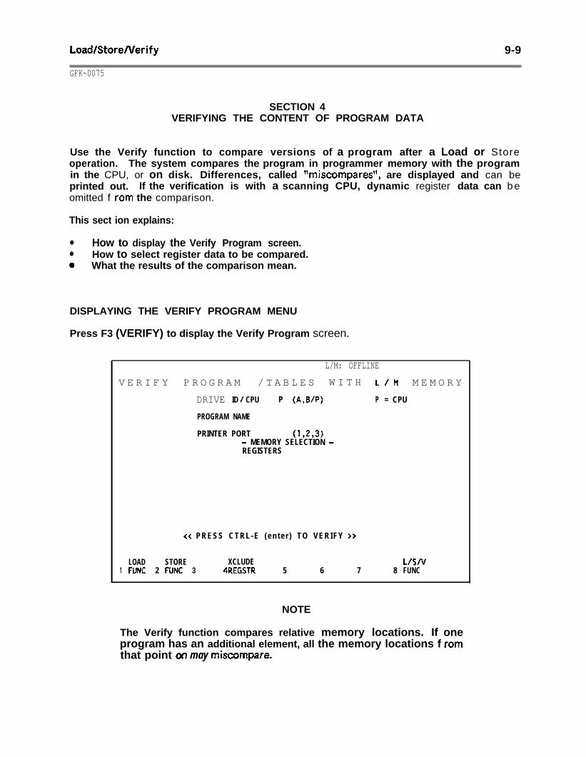
Load/StoreNerify 9-9
GFK-0075
SECTION 4VERIFYING THE CONTENT OF PROGRAM DATA
Use the Verify function to compare versions of a program after a Load or Storeoperation. The system compares the program in programmer memory with the programin the CPU, or on disk. Differences, called **miscompares*‘, are displayed and can beprinted out. If the verification is with a scanning CPU, dynamic register data can beomitted f ram the comparison.
This sect ion explains:
l How to display the Verify Program screen.l How to select register data to be compared.0 What the results of the comparison mean.
DISPLAYING THE VERIFY PROGRAM MENU
Press F3 (VERIFY) to display the Verify Program screen.
.
L/M: OFFLINE
V E R I F Y P R O G R A M / T A B L E S W I T H L/M M E M O R Y
DRIVE ID / CPU P (A,B/P) P = CPU
PROGRAM NAME
PRINTER PORT (1,293)- MEMORY SELECTION -REGISTERS
<< PRESS CTRL-E (en te r ) TO VERIFY >>
LOAD STORE XCLUDE L/S/v1 FUNC 2 FONC 3 4REGSTR 5 6 7 8 FUNC
NOTE
The Verify function compares relative memory locations. If oneprogram has an additional element, all the memory locations f ramthat point on may miscompare.
9-l 0 LoadBtoreNerify
GFK-0075
YERIFYING PROGRAM DATA
To compare the program in programmer memory with the version in the CPU, or on disk:
1 .
2 .
3 .
4 .
5 .
6 .
7 .
With the cursor at DRIVE ID/CPU, enter the character that represents the drivewhere the program to be compared is located. Enter the drive location of theprogram file, or the letter P for the CPU.
If the comparison is to a file on disk, move the cursor to PROGRAM NAME and enterthe name of the program.
To print a copy of the differences, move the cursor to PRINTER PORT and enter thenumber of the port to which the printer is connected. Be sure that the printer ison-line and connected to the system.
To exclude register data from the comparison, press the Exclude Registers (F4) keyto exclude the contents of the registers. The function of the key then becomesVerify Registers.
Press CTRL-E or the Enter key to begin the Verify operation. While the comparisonis underway, the screen displays the BUSY message. Also, two key functions, Abort(F6) and Pause (I%, are displayed.
To temporarily halt the Verify operation, press F7 (PAUSE). To resume theVerification, press F7 again.
To end a verification before it is finished, press F6 (ABORT). Respond to the promptto confirm the abort. This ends the function completely.
NOTE
The CPU must be unlocked to compare the program in programmermemory with the program in the CPU.
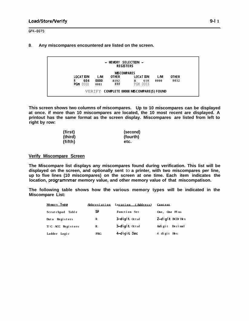
Load/StoreNerify 9-l 1
GFK-0075
8 . Any miscompares encountered are listed on the screen.
- MEMORY SELECTION -REGISTERS
MISCOMPARESLOCAT ION L/M OTHER LOCAT ION L/M OTHERR 604 0000 8192 R 610 0000 0032PGM 0000 0081 FFF PGM 0003
VERIFY COMPLETE 00008 MISCOMPARE(S) FOUND
This screen shows two columns of miscompares. Up to 10 miscompares can be displayedat once. if more than 10 miscompares are located, the 10 most recent are displayed. Aprintout has the same format as the screen display. Miscompares are listed from left toright by row:
(first)(third)(fifth)
(second)(fourth)etc.
Verify Miscompare Screen
The Miscompare list displays any miscompares found during verification. This list will bedisplayed on the screen, and optionally sent to a printer, with two miscompares per line,up to five lines (10 miscompares) on the screen at one time. Each item indicates thelocation, programnmer memory value, and other memory value of that miscompatison.
The following table shows how the various memory types will be indicated in theMiscompare List:
Memorv TVD~ Abbreviation Location (Address) Content
Scratchpad Table SP Function Set One, One Plus
Data Registers R 3-digit Octal 2-digit BCD/Hex
T/C ACC Registers R 3-digit Octal &digit Decimal
Ladder Logic PRG 4-digit Dee 4 digit Hex
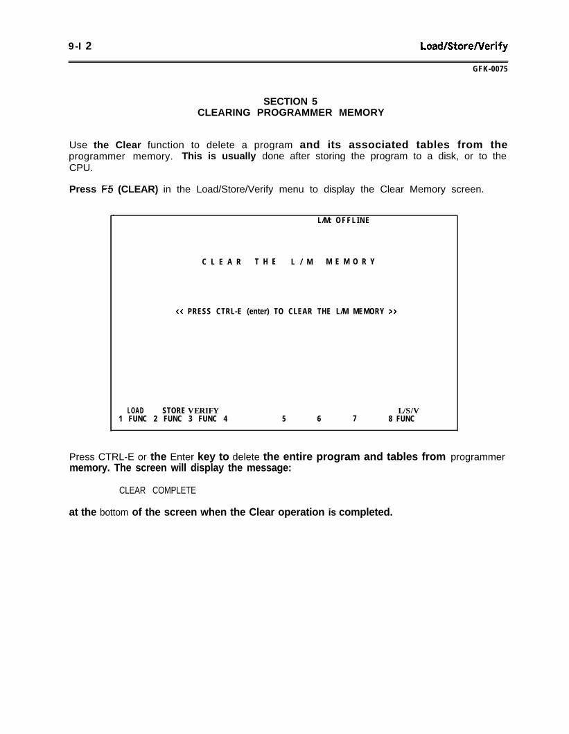
9-I 2 LoadlStoreNerify
GFK-0075
SECTION 5CLEARING PROGRAMMER MEMORY
Use the Clear function to delete a program and its associated tables from theprogrammer memory. This is usually done after storing the program to a disk, or to theCPU.
Press F5 (CLEAR) in the Load/Store/Verify menu to display the Clear Memory screen.
.L/M: OFFL INE
C L E A R T H E L / M M E M O R Y
<x PRESS CTRL-E (enter) TO CLEAR THE L/M MEMORY >>
LOAD STORE VERIFY L/S/V1 FUNC 2 FUNC 3 FUNC 4 5 6 7 8 FUNC
Press CTRL-E or the Enter key to delete the entire program and tables from programmermemory. The screen will display the message:
CLEAR COMPLETE
at the bottom of the screen when the Clear operation is completed.
Configuration Setup 1 O-l
CFK-0075
CHAPTER 10CONFIGURATION SETUP
The Configuration Setup menu provides entry to the Communications Setup and MachineSetup functions.
This chapter contains the fo
Section 1 w The Conf igurat
lowing sect ions:
on Setup Meqg: Section 1 explains the Conf igutation Setupmenu, and summarizes the function keys.
Section 2. Setting Up Communications with the CPU: Section 2 provides instructions toset up parameters for communicating with the CPU.
Section 3. CPU Password Protection: Section 3 provides instructions tothe CPU and to change the password.
Section 4. The Machine Setup Menu: Section 4 provides instructions tocolors if you are programming on a computer with a color monitor.
ock or unlock
select display
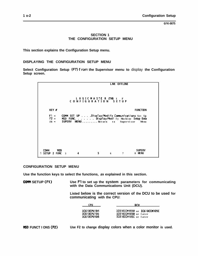
1 o-2 Configuration Setup
GFK-0075
SECTION 1THE CONFIGURATION SETUP MENU
This section explains the Configuration Setup menu.
DISPLAYING THE CONFIGURATION SETUP MENU
Select Configuration Setup (F7) f ram the Supervisor menu to display the ConfigurationSetup screen.
L/M: OFFLINE
L 0 G I C M A S T E R (TM) 1 FC O N F I G U R A T I O N S E T U P
KEY # FUNCTION
Fl - COMM SET UP . . .F2 -
.Display/Modify Comnunications Set UpMS0 FUNC. . . . . . . Di splayhlodi fy Machine Setup Data
F8 - SUPERV MENU . . . . . . . . . Return to Supervisor Menu
COMM MS0 SUPERV1 SETUP 2 FUNC 3 4 5 6 7 8 MENU
CONFIGURATION SETUP MENU
Use the function keys to select the functions, as explained in this section.
COMH SETUP (Fl) Use Fl to set up the system parameters for communicatingwith the Data Communications Unit (DCU).
Listed below is the correct version of the DCU to be used forcommunicating with the CPU:
CPU
IC6lOCPUlW IC6lOCCMlO5B or IC610CCMlO5CIC61OCPU105 IC610CCM1056 or laterIC61OCPU106 ICdlOCCMlOSC or later
MSD FUNCT I ONS (F2) Use F2 to change display colors when a color monitor is used.
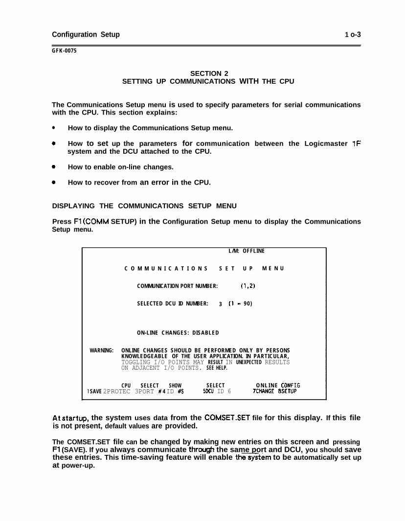
Configuration Setup 1 o-3
GFK-0075
SECTION 2SETTING UP COMMUNICATIONS WITH THE CPU
The Communications Setup menu is used to specify parameters for serial communicationswith the CPU. This section explains:
l How to display the Communications Setup menu.
a How to set up the parameters for communication between the Logicmaster 1Fsystem and the DCU attached to the CPU.
a How to enable on-line changes.
0 How to recover from an error in the CPU.
DISPLAYING THE COMMUNICATIONS SETUP MENU
Press Fl (COMM SETUP) in the Configuration Setup menu to display the CommunicationsSetup menu.
L/M: OFFLINE
C O M M U N I C A T I O N S S E T U P M E N U
COMMUNICATION PORT NUMBER: ma
SELECTED DCU ID NUMBER: 3 (1 - 90 )
ON-LINE CHANGES: DISABLED
WARNING: ONLINE CHANGES SHOULD BE PERFORMED ONLY BY PERSONSKNOWLEDGEABLE OF THE USER APPLICATION. IN PARTICULAR,TOGGLING I/O POINTS MAY RESULT IN UNEXPECTED RESULTSON ADJACENT I/O POINTS. SEE HELP.
CPU SELECT SHOW SELECT1 SAVE 2PROTEC 3PORT # 4 ID #S SDCU ID 6
O N L I N E CONFIG‘ICHANGE 8SETUP
At startup, the system uses data from the COMSET.SET file for this display. If this fileis not present, default values are provided.
The COMSET.SET file can be changed by making new entries on this screen and pressingFl (SAVE). If you always communicate through the same port and DCU, you should savethese entries. This time-saving feature will enable th=tem to be automatically set upat power-up.
1 o-4 Configuration Setup
GFK-0075
CHANGING THE COMMUNICATIONS SETUP SCREEN
Change the entries on the Communications Setup screen to describe your system.Changes are made in two ways:
A. Port Number and DCU ID fields: Type the entry into the work area and press theappropriate function key.
B. On-Line Changes fields: Press the appropriate function key to toggle the selections.
Cancelinca Entries on the Communications Setup Screen
To exit this screen and return to the values that were displayed when the screen wasentered, press F9 or the Abort key. The screen displays:
PRESS CONFIRM TO ABORT, ANY OTHER KEY TO PROCEED
Press ALT-X (Confirm or Shift-O) to exit, or press any other key to cancel the abort.
COMMUNICATIONS SETUP SCREEN: DEFINITIONS
Refer to the following definitions when making changes to the Communications Setupscreen,
COMMUNICATION PORT NO. This entry is the number of the DCU communicationport. The menu displays the numbers of the ports thatwere operable when the system was started up. Toselect the port, enter the desired port number into anyfield of the work area and press F3 (SELECT PORT #).To deselect a port, leave the work area blank and pressF3. A port currently selected for communications mustbe deselected if it is to be used for other Logicmaster1 F functions.
The port selected must be configured to match the DCUto which the system is connected. If the port is on theCombination Adapter card of the Workmaster computer,it can only be RS-232. Therefore, it can only beconnected to a DCU card through the RS-232/R%422Adapter Unit, IC630CCM390.
If the port is on the Asynchronous/Joystick card, it maybe configured for either RS-232 or RS-422. If it is setup for RS-232, it can only be connected to a DCU cardthrough the RS-232/R%422 Adapter Unit,iC630CCM390. If it is set up for N-422, it may be useddirectly with a DCU through a Workmaster-to-DCUcable, IC630CBL391 l
Mul t idrop configurations (one Logicmaster 1 F systemconnected to more than one DCU) must be done withRS-422. Refer to GEK-90477 for more information.
ON-LINE CHANGES
plus the number of each currently-available DCU. For anetwork interface with more than eight DCUs, press F6 again,as needed, to display additional DCU IDS.
To cancel the polling of DCU IDS, press F9 or the Abort key.The screen prompts:
PRESS CONFIRM TO ABORT , ANY KEY TO CONTINUE
Press ALT-X (Confirm or Shift-O) to confirm the abort, orany other key to continue polling the DCU IDS.
Configuration Setup
GFK-0075
1 o-5
COMMUNICATIONS SETUP SCREEN: DEFINITIONS (Continued)
SELECTED DCU ID Enter the ID number of the DCU (from 1 to 90) that will becommunicating with the system. After entering the number,press F5 (SELECT DCU ID). The number will be entered intothe field, and the system will immediately begincommunicating with that DCU.
To display the IDS of the currently-available DCUs within theparentheses to the right, press F4 (SHOW ID #S). The screenwill display:
POLLING DCU ID NUMBER:
Press F7 (ONLINE CHANGE) to select the ability to use thesystem’s on-line change features. This allows you to changeregisters, I/O points, or constants while the programmer isswitched on-line.
1 WARNING (
Exclusive single bit on-l ine c h a n g e s o fdiscrete I/O are not supported in either t h eSeries One (Model E) Data Communications Unitor the Series One Plus Data CommunicationsUnit. The toggling function is accomplishedby (1) reading a byte wide I/O group from theCPU containing the t/O point to be toggled,(2) setting the I/O point to be toggled, and(3) writing the entire byte wide I/O groupback to the CPU memory.
If the CPU changed the status of any l/Opoints in that group during the read-set-writecycle for l/O toggling, the new status snay beoverwritten. Because this could produceunexpected and potentially hazardous results,caution is necessary when toggling discretel/O. Toggling l/O must be performed when userlogic memory is cleared to avoidunexpected or hazardous results.
any
1 O-6 Configuration Setup
GFK-0075
COMMUNICATIONS SETUP SCREEN: DEFINITIONS (Continued)
SAVE Press Fl to create a file named COMSET.SET on thesystem start-up diskette. The system diskette must bewrite-enabled to receive the file. (The tab in thewindow on the diskette must be closed.) The systemdiskette must also be in the default drive. This file willstore the current settings for the Communications Setupscreen, except the listing of available DCU IDS. Thesystem will read the contents of this file at start up.
If the COMSET.SET file is present when theLogicmaster 1F software is loaded, the saved values willbe used to set the communications parametersautomat ical ly. If COMSET.SET is not present at loadtime, the communications parameters are set to defaultvalues. (These default values include: No port selected,and DCU ID 3.)
CONFIGURATION SETUP Press F8 (CONFIG SETUP) to return to theConfiguration Setup menu.
RECOVERING FROM AN ERROR IN THE CPU
If the CPU contains a program with a fatal error in it and the DCU is power cycled,the Logicmaster system may not be able to communicate with the DCUKPU evenafter power is restored. On power-up, the CPU performs a grammar check and theresult is passed to the DCU. The DCU then inhibits communications until the erroris cleared.
This situation is more likely to occur if the program was created or modified usingeither the handheld programmer or the LCD portable programmer. Creating ormodifying a program directly on the Logicmaster system will usually prevent thissituation.
If the Logicmaster system will not communicate with your CPU through the DataCommunications Unit, even though the system was working previously, you shouldfollow this procedure:
1 .
2 .
4 .
5 .
6 .
Take the DCU off-line, and attach a handheld programmer.
Press CLR CLR SCH to perform a manual grammar check. The error type(if any) will be displayed in the window.
Press CLR NXT to obtain the error address.
Correct the error using the appropriate edit keys. You may also clear theprogram by pressing CLR CLR SHF 3 4 8 DEL NXT*
Remove the handheld programmer, and place the DCU back on-line. TheLogicmaster system should now be able to communicate properly with the CPUthrough the Data Communications Unit.
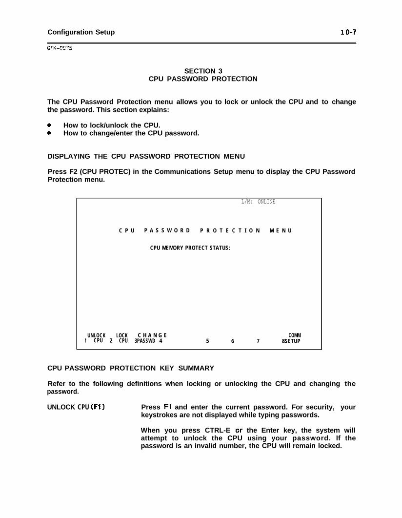
Configuration Setup 1 O-7
SECTION 3CPU PASSWORD PROTECTION
The CPU Password Protection menu allows you to lock or unlock the CPU and to changethe password. This section explains:
0 How to lock/unlock the CPU.0 How to change/enter the CPU password.
DISPLAYING THE CPU PASSWORD PROTECTION MENU
Press F2 (CPU PROTEC) in the Communications Setup menu to display the CPU PasswordProtection menu.
.L/M: ONLINE
C P U P A S S W O R D P R O T E C T I O N M E N U
CPU MEMORY PROTECT STATUS:
UNLOCK LOCK C H A N G E COMM1 CPU 2 CPU 3PASSWD 4 5 6 7 8SETUP
CPU PASSWORD PROTECTION KEY SUMMARY
Refer to the following definitions when locking or unlocking the CPU and changing thepassword.
UNLOCK CPU (Fl ) Press F7 and enter the current password. For security, yourkeystrokes are not displayed while typing passwords.
When you press CTRL-E or the Enter key, the system willattempt to unlock the CPU using your password. If thepassword is an invalid number, the CPU will remain locked.
1 O-8 Configuration Setup
GFK-0075
CPU PASSWORD PROTECTION SCREEN: DEFINITIONS (Continued)
if you press the wrong key while entering the password, youcannot use the Backspace or Delete keys to correct yourerror. You must continue with this attempt to unlock theCPU, which will be unsuccessful, and then try again.
LOCK CPU (F2) Press F2. The system will attempt to lock the CPU. Notethat the CPU will remain unlocked if the current password iszero. In that case, the password must be changed beforelocking the CPU.
CHANGE PASSWORD (F3) Press F3 and enter the current password. Your keystrokes arenot displayed while typing in passwords. After entering thecurrent password, you must enter the new password twice toinsure accurate entry. Then the system will try to change thepassword. if the current password entry is an invalid number,a message will be displayed and the password change will notoccur.
If you press the wrong key while entering the password, youcannot use the Backspace or Delete keys to correct yourerror. You must continue with this attempt to unlock theCPU, which will be unsuccessful, and then try again.
UNLOCKING THE CPU
To unlock the CPU, follow these steps:
1 . With the Logicmaster system in the On-Line mode only, press Fl (UNLOCK CPU) inthe CPU Password Protection menu. The following message is displayed:
TYPE CPU PASSWORD (UP TO 4 DECIMAL DIGITS)
2. Type thepasswordstatus wil
CPU
However,
THEN PRESS << ENTER >>
current password, and press CTRL-E or the Enter key. If the correctis entered, the system- will unlock the CPU.be displayed as UNLOCKED:
MEMORY PROTECT STATUS: UNLOCKED
‘he CPU memory protect
if the password entered is incorrect, the CPU wil remain locked.
Configuration Setup IO-9
LOCKING THE CPU
To lock the CPU, follow these steps:
1 . With the Logicmaster system in the On-Line mode only, press F2 (LOCK CPU) in theCPU Password Protection menu. The system will lock the CPU, as indicated by thestatus of the CPU displayed on the screen:
CPU MEMORY PROTECT STATUS: LOCKED
2 . if the current password, however, is zero, the system will remain unlocked and thefollowing message will be displayed:
PASSWORD = 0000; CPU CANNOT BE LOCKED
The system will remain unlocked until you change the password.
To change the password, follow this procedure: ,
1 . Press F3 (CHANGE PASSWD) in the CPU Password Protection menu. The followingmessage is displayed:
TYPE CURRENT PASSWORD (UP TO 4 DECIMAL DIGITS)THEN PRESS << ENTER >>
2. Type the current password, and press CTRL-E or the Enter key. The followingmessage is displayed:
TYPE NEW CPU PASSWORDTHEN PRESS << ENTER >>
3. Type the new password, and press CTRL-E or the Enter key. The following messageis displayed:
RETYPE CPU PASSWORD FOR VERIFICATIONTHEN PRESS << ENTER >>
4. Retype your new password and press CTRL-E or the Enter key. The system willverify this password with the new password you entered in step 3. If the twopasswords agree, the status of the CPU will be changed to LOCKED.
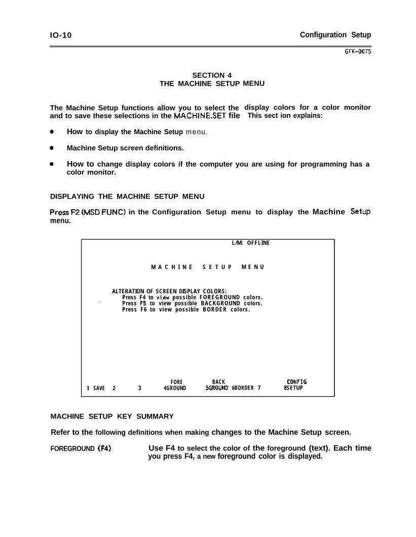
IO-10 Configuration Setup
SECTION 4THE MACHINE SETUP MENU
The Machine Setup functions allow you to select the display colors for a color monitorand to save these selections in the MACHlNE.SET file This sect ion explains:
0 How to display the Machine Setup menu.
0 Machine Setup screen definitions.
GFK-0075
0 How to change display colors if the computer you are using for programming has acolor monitor.
DISPLAYING THE MACHINE SETUP MENU
Press F2 (MSD FUNC) in the Configuration Setup menu to display the Machine Setupmenu.
L/M: OFFLINE
M A C H I N E S E T U P M E N U
ALTERATION OF SCREEN DISPLAY COLORS:Press F4 to vi@w possible FOREGROUND colors..Press FS to view possible BACKGROUND colors.Press F6 to view possible BORDER colors.
FORE BACK CONFIGI SAVE 2 3 4GROUND SGROUND 6BORDER 7 8SETUP
MACHINE SETUP KEY SUMMARY
Refer to the following definitions when making changes to the Machine Setup screen.
FOREGROUND (F4) Use F4 to select the color of the foreground (text). Each timeyou press F4, a new foreground color is displayed.
Configuration Setup 10-11
MACHINE SETUP KEY SUMMARY (Continued)
BACKGROUND (F5) Use F5 to select the color of the background. Each time youpress F5, a new background color is displayed. The systemwill prevent you from selecting matching foreground andbackground colors.
BORDER (F6)
SAVE (Fl )
If your system uses a Color Graphics Adapter (CGA), you canchange the border color by pressing F6. The EnhancedGraphics Adapter (EGA) will always display a black border.
Color selections take effect immediately and remain activewhile the system is running. Press Fl to save the selections inthe MACtilNE.SET file on the startup disk. These selectionswill then be used automatically whenever the system isstarted.
CONFIGURATIONSETUP (F8) Press F8 key to return to the Configuration Setup menu.
CHANGING SCREEN COLORS
If you are using a color monitor, you can change the color of the text, background, and/orscreen border. To change colors, follow these steps:
1 . Select MSD functions from the Configuration Setup menu.
2 . Use the function keys F4-F6 to toggle through the 16 different color selections foreach item.

Utilities
GFK-0075
11-l
CHAPTER 11UTILITIES
The Utilities functions are used for disk and file management, and for configuring theserial port(s).
This chapter explains how to use the Utilities functions. Refer to the appropriatesect ions.
Section 1. The Utilities Menu: Section 1 explains how to access the Utilities menu, anddefines the Utilities function keys.
Section 2. Duplicating the Master Software: Refer to section 2 for instruct ions toduplicate the original Logicmaster 1 F software diskettes.
Section 3. Using the File Utilities: Section 3 explains how to copy and delete files. Italso explains how to display or print a directory of files.
Section 4. Setting Up the Serial Ports: Section 4 explains how to examine and modifythe serial port parameters.
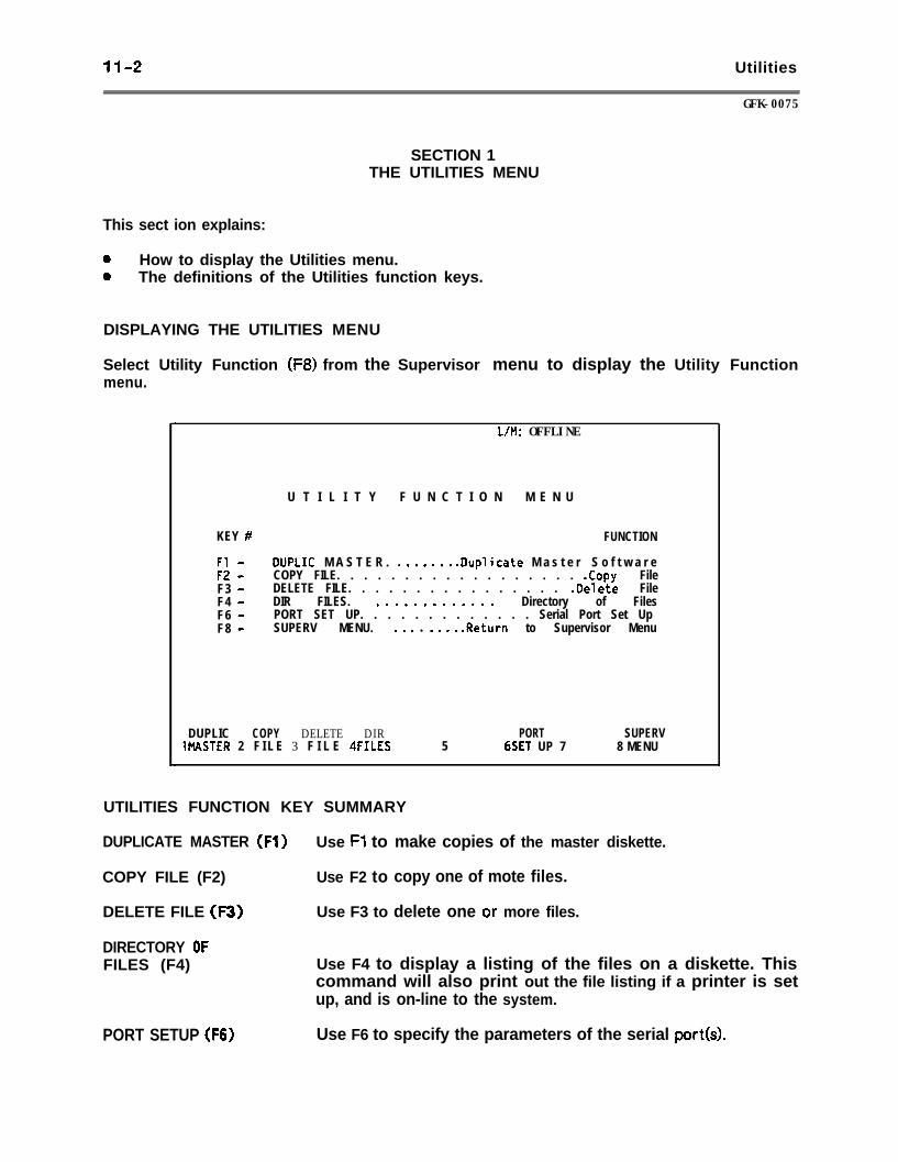
11-2 Utilities
GFK-0075
SECTION 1THE UTILITIES MENU
This sect ion explains:
0 How to display the Utilities menu.0 The definitions of the Utilities function keys.
DISPLAYING THE UTILITIES MENU
Select Utility Function (F8) from the Supervisor menu to display the Utility Functionmenu.
L/M: OFFLINE
U T I L I T Y F U N C T I O N M E N U
KEY # FUNCTION
Fl - DUPLIC M A S T E R . . . . . . . . .Duplicate M a s t e r S o f t w a r eF2 - COPY FILE. . . . . . . . . . . . . . . . . . .Copy FileF3 - DELETE FILE. . . . . . . . . . . . . . . . .Delete FileF4 - DIR FILES. . . . . . . . . . . . . . Directory of FilesF6 - PORT SET UP. . . . . . . . . . . . . Serial Port Set UpF8 - SUPERV MENU. . . . l . . . . .Return to Supervisor Menu
DUPLIC COPY DELETE DIRMASTER 2 F I L E 3 F I L E 4FILES 5
PORT SUPERV6SET UP 7 8 MENU
UTILITIES FUNCTION KEY SUMMARY
DUPLICATE MASTER (Fl) Use Fl to
COPY FILE (F2) Use F2 to
DELETE FILE (F3) Use F3 to
DIRECTORY OF
make copies of the master diskette.
copy one of mote files.
delete one or more files.
FILES (F4)
PORT SETUP (F6)
Use F4 to display a listing of the files on a diskette. Thiscommand will also print out the file listing if a printer is setup, and is on-line to the system.
Use F6 to specify the parameters of the serial port(s).
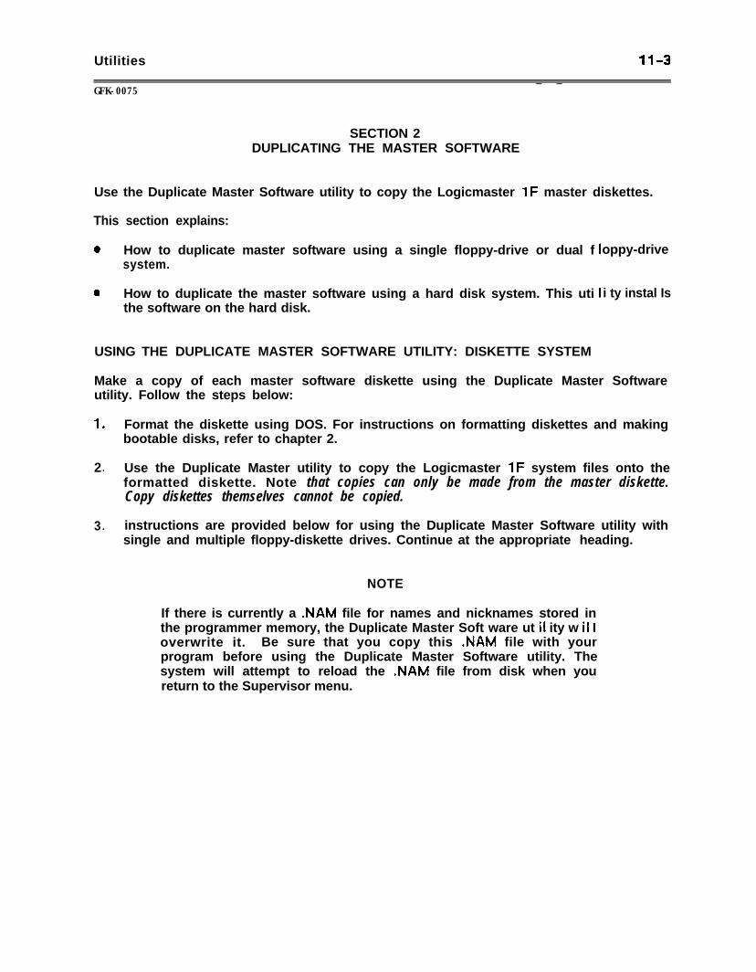
Utilities 11-3_ _
GFK-0075
SECTION 2DUPLICATING THE MASTER SOFTWARE
Use the Duplicate Master Software utility to copy the Logicmaster 1F master diskettes.
This section explains:
0 How to duplicate master software using a single floppy-drive or dual fsystem.
0 How to duplicate the master software using a hard disk system. This utithe software on the hard disk.
oppy-drive
i ty instal Is
USING THE DUPLICATE MASTER SOFTWARE UTILITY: DISKETTE SYSTEM
Make a copy of each master software diskette using the Duplicate Master Softwareutility. Follow the steps below:
1 . Format the diskette using DOS. For instructions on formatting diskettes and makingbootable disks, refer to chapter 2.
2. Use the Duplicate Master utility to copy the Logicmaster 1F system files onto theformatted diskette. Note that copies can only be made from the master diskette.Copy diskettes themselves cannot be copied.
3 . instructions are provided below for using the Duplicate Master Software utility withsingle and multiple floppy-diskette drives. Continue at the appropriate heading.
NOTE
If there is currently a .NAM file for names and nicknames stored inthe programmer memory, the Duplicate Master Soft ware ut il ity w il Ioverwrite it. Be sure that you copy this .NAM file with yourprogram before using the Duplicate Master Software utility. Thesystem will attempt to reload the .NAM file from disk when youreturn to the Supervisor menu.
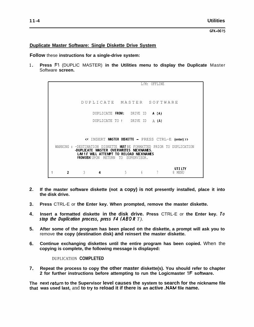
11-4 Utilities
GFK-0075
Duplicate Master Software: Single Diskette Drive System
Follow these instructions for a single-drive system:
1 .
2 .
3 .
4 .
5 .
6 .
7 .
The next return to the Supervisor level causes the system to search for the nickname filethat was used last, and to try to reload it if there is an active .NAM file name.
Press Fl (DUPLIC MASTER) in the Utilities menu to display the Duplicate MasterSoftware screen.
L/M: OFFLINE
D U P L I C A T E M A S T E R S O F T W A R E
DUPLICATE FROM : DRIVE ID A (A)
DUPLICATE TO : DRIVE ID A (A)
<< INSERT MASTER DISKETTE - PRESS CTRL-E (enter) >>
WARNING : -DESTINATION DISKETTE MUST BE FORMATTED PRIOR TO DUPLICATION-DUPLICATE MASTER OVERWRITES NICKNAMES.
L/M 1 F WILL ATTEMPT TO RELOAD NICKNAMESFROM DISK UPON RETURN TO SUPERVISOR.
UT1 LTY1 2 3 4 5 6 7 8 MENU
If the master software diskette (not a copy) is not presently installed, place it intothe disk drive.
Press CTRL-E or the Enter key. When prompted, remove the master diskette.
Insert a formatted diskette in the disk drive. Press CTRL-E or the Enter key. TOstop the Duplication process, press F4 (A60 R T).
After some of the program has been placed on the diskette, a prompt will ask you toremove the copy (destination disk) and reinsert the master diskette.
Continue exchanging diskettes until the entire program has been copied. When thecopying is complete, the following message is displayed:
DUPLICATION COMPLETED
Repeat the process to copy the other master diskette(s). You should refer to chapter2 for further instructions before attempting to run the Logicmaster 1F software.
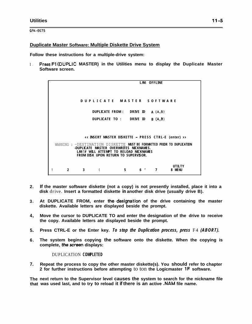
Utilities
GfK-0075
11-5
Duplicate Master Software: Multiple Diskette Drive System
Follow these instructions for a multiple-drive system:
1 .
2 .
3 .
4 .
5 .
6 .
7 .
The next return to the Supervisor level causes the system to search for the nickname filethat was used last, and to try to reload it if there is an active .NAM file name.
Press Fl (DUPLIC MASTER) in the Utilities menu to display the Duplicate MasterSoftware screen.
.L/M: OFFLINE
D U P L I C A T E M A S T E R S O F T W A R E
DUPLICATE FROM : DRIVE ID A (A,B)
DUPLICATE TO : DRIVE ID B (A,B)
cc INSERT MASTER DISKETTE - PRESS CTRL-E (en te r ) >>
WARNING : -DESTINATION DISKETTE MUST BE FORMATTED PRIOR TO DUPLICATION-DUPLICATE MASTER OVERWRITES NICKNAMES.
L/M 1F WILL ATTEMPT TO RELOAD NICKNAMESFROM DISK UPON RETURN TO SUPERVISOR.
UTILTY1 2 3 4 5 6 ’ 7 8 MENU
If the master software diskette (not a copy) is not presently installed, place it into adisk drive. Insert a formatted diskette in another disk drive (usually drive B).
At DUPLICATE FROM, enter the,designation of the drive containing the masterdiskette. Available letters are displayed beside the prompt.
Move the cursor to DUPLICATE TO and enter the designation of the drive to receivethe copy. Available letters ate displayed beside the prompt.
Press CTRL-E or the Enter key. To stop the Duplication process, press F4 (ABORT).
The system begins copying the software onto the diskette. When the copying iscomplete, the screen displays:
DUPLICATION COMPLETED
Repeat the process to copy the other master diskette(s). You should refer to chapter2 for further instructions before attempting to ton the Logicmaster 1F software.
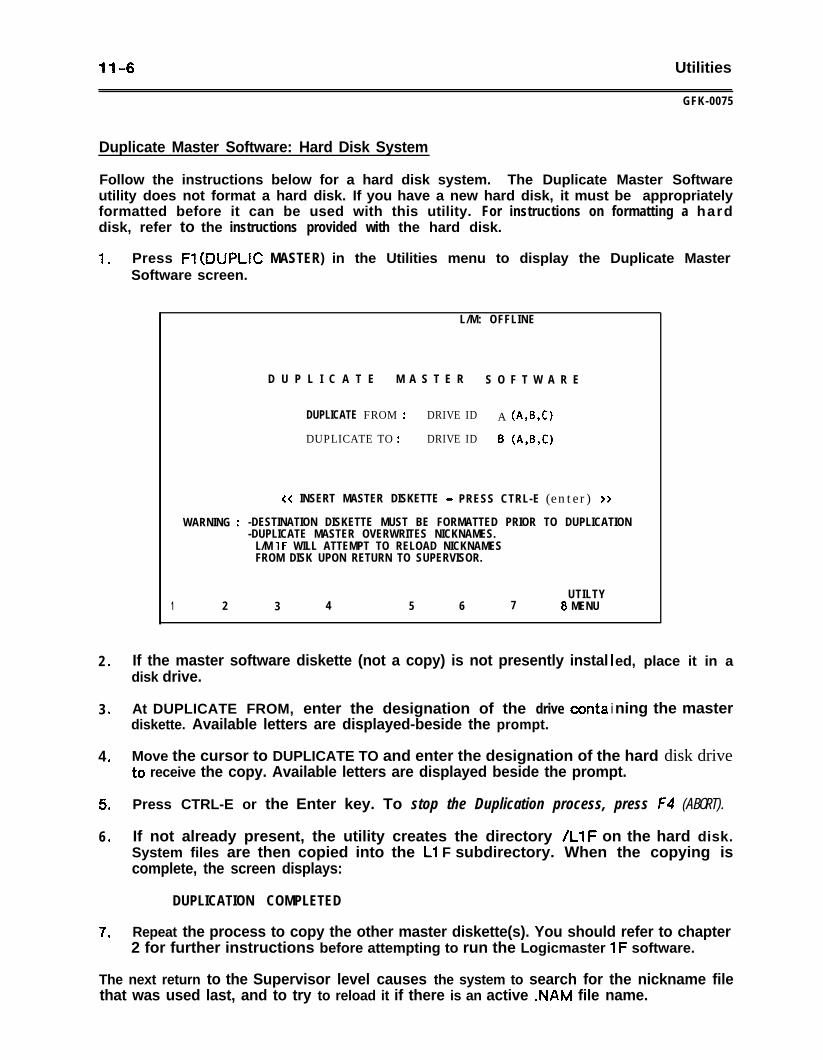
11-6 Utilities
GFK-0075
Duplicate Master Software: Hard Disk System
Follow the instructions below for a hard disk system. The Duplicate Master Softwareutility does not format a hard disk. If you have a new hard disk, it must be appropriatelyformatted before it can be used with this utility. For instructions on formatting a harddisk, refer to the instructions provided with the hard disk.
1 .
2 .
3 .
4 .
5 .
6 .
7 .
Press Fl (DUPLIC MASTER) in the Utilities menu to display the Duplicate MasterSoftware screen.
L/M: OFFLINE
D U P L I C A T E M A S T E R S O F T W A R E
DUPLICATE FROM : DRIVE ID A (A,B,C)
DUPLICATE TO : DRIVE ID 8 (A,&0
<< INSERT MASTER DISKETTE - PRESS CTRL-E (enter) >>
WARNING : -DESTINATION DISKETTE MUST BE FORMATTED PRIOR TO DUPLICATION-DUPLICATE MASTER OVERWRITES NICKNAMES.
L/M 1F WILL ATTEMPT TO RELOAD NICKNAMESFROM DISK UPON RETURN TO SUPERVISOR.
UTILTY1 2 3 4 5 6 7 8 MENU
If the master software diskette (not a copy) is not presently instaldisk drive.
At DUPLICATE FROM, enter the designation of the drive conta idiskette. Available letters are displayed-beside the prompt.
ed, place it in a
ning the master
Move the cursor to DUPLICATE TO and enter the designation of the hard disk driveto receive the copy. Available letters are displayed beside the prompt.
Press CTRL-E or the Enter key. To stop the Duplication process, press F4 (ABORT).
If not already present, the utility creates the directory /LlF on the hard disk.System files are then copied into the Ll F subdirectory. When the copying iscomplete, the screen displays:
DUPLICATION COMPLETED
Repeat the process to copy the other master diskette(s). You should refer to chapter2 for further instructions before attempting to run the Logicmaster 1F software.
The next return to the Supervisor level causes the system to search for the nickname filethat was used last, and to try to reload it if there is an active .NAM file name.
Utilities
GFK-0075
11-7
SECTION 3USING THE FILE UTILITIES
The system stores all program data as files. This section explains:
a How to use file names and ‘*w i Idcards”.0 How to copy files.0 How to use the Copy utility to rename backup files.0 How to delete files.0 How to display or print a directory of files.
FILE NAMES
Each file has a unique name by which the system identifies it. The name you give aprogram becomes the basic file name for that program, and for other files associatedwith it.
Reserved File names
Do not begin a file name with any of the following reserved system names: CON, AUX,COMl, COM2, PRN, LPTl, LPT2, LPT3, or NUL.
DO not use the witdcard characters * or ? as part of a file name.
Using ‘7Nildcards” to Represent Parts of File names
When using the File Utilities (Directory, Copy File, and Delete File), *‘wildcard”characters can be used to represent parts of existing file names. The two wildcardcharacters are:
* Asterisk, which can be used to represent one or more characters in a filename. For example, an asterisk may represent all files with the sameextension (*.LAD) or all extensions to the same file name (PROGRAMI*).
? Question mark, which can be used to represent one character in a file nameFor example, PROGRAM?.LAD and PROGRAM1 .L??.
Both wildcatd characters can be used together. For example, PROGRAM?.* means allfiles beginning with PROGRAM.
NOTE
When using w ildcard characters in a file name, you must also usethe period character between the main part of the file name andthe extension (for example, PROG*.*).
11-8 Util it ies
UK-0075
PROGRAM FiLES
A program is stored as more than one type of file. The system automatically gives eachtypz sf file a three-character file name extension. The extension is part of the filename, and differentiates one program file from another. When entering a file name andan extension, be sure to include the period between the file name and the extension.
The following list defines the file name extensions used by the Logicmaster 1F system.
name l LAD The .LAD file contains the ladder diagram, properly formatted fortransfer to the CPU. This file uses two bytes of storage for each word oflogic. The .LAD file includes the registers, I/O status, and user logic \associated with the ladder diagram. The .LAD file is created in the EditProgram function if there is an active file name when you enter userlogic.
name. LBU
name. RDF
name l RBU
name. TXT
name. NAM
name. NBU
name l EXP
name. EBU
This file contains the backup copy of an .LAD file that is created if aprogram backup is selected at the beginning of the Edit Programfunction. You must specify Y for YES in response to the followingprompt:
DO YOU WISH TO BACKUP PROGRAM? (Y/N)
If program backup is not selected, an .LBU file is not created.
The .RDF file contains the formats that will be used for referencedisplays and printouts. The RDF file is created when a file name isactive. Initially, the file contains default formats supplied by thesystem. The Display References utility changes this file.
The .RBU file is the backup file for the .RDF file. This file is created atthe beginning of the Edit Program function when you specify Y for YES inresponse to the backup prompt.
The .TXT file is the text output file that is created when the program isstored for later printing (in Background mode), using the Print Programfunction.
The .NAM file contains program names and nicknames. The .NAM file iscreated if there is an active file name when you enter names ornicknames. _
The .NBU file is the backup file for the .NAM file. This file is created atthe beginning of the Edit Program function when you specify Y for YES inresponse to the backup prompt.
The .EXP file contains the program rung explanations and coil labels.The .EXP file is created if there is an active file name when you enter arung explanation or coil label.
The E&U file is the backup file for the .EXP file. This file is created atthe beginning of the Edit Program function when you specify Y for YES inresponse to the backup prompt.
Utilities
GFK-0075
11-9
If you had a program named PROGRAtvll, the ladder diagram would be stored as the filenamed PROGRAMl.LAD. Other files for that program would be named as describedabove. For example, the format for the reference displays would be namedPROGRAM1 .RDF.
OTHER FILES OF INTEREST
In addition to the program files, other files of interest are:
Fx. DEF where x = l-8. The Fx.DEF file contains the user-defined keys created inTeach mode.
COMSET s SET The Communications Setup file contains the communications setup data.The system creates or updates this file when the Save (Fl) key is pressedfrom the Communications Set Up’menu.
PRINTER.SET The Printer Setup file contains the printer data. The system creates orupdates this file when the Save (FS) key is pressed from the DefinePrinter screen.
PORTn . PSU The PORT1 .PSU or PORTZPSU file contains the serial port setupinformation entered with the Setup Serial Port utility.
MACHINE.SET The Machine Setup file contains the color monitor default colors.
COPYING FILES
The Copy File utility is used to copy one or more files. Copying may be done betweenserial ports or disks.
NOTE
If there is currently a .NAM file for names and nicknames stored inthe programmer memory, the Copy File utility will overwrite it. Besure that you copy this .NAM file with your program before usingthe Copy File utility. The system will attempt to reload the .NAMfile from disk when you return to the Supervisor menu.
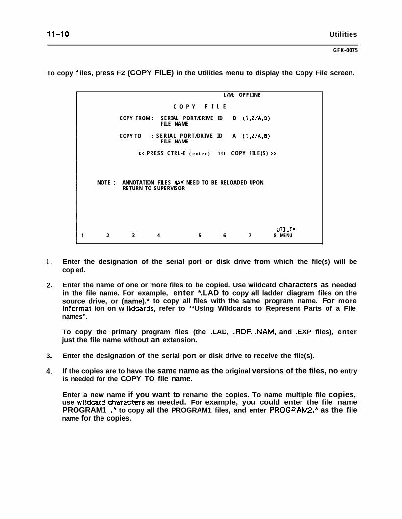
11-10 Utilities
To copy
GFK-0075
iles, press F2 (COPY FILE) in the Utilities menu to display the Copy File screen.
L/M: OFFLINE
C O P Y F I L E
COPY FROM : SERIAL PORT/DRIVE ID B (1,2/A,B)FILE NAME
COPY TO : SERIAL PORT/DRIVE ID A (1,2/A,B)FILE NAME
<< PRESS CTRL-E (enter) TO COPY FILE(S) >>
NOTE : ANNOTATION FILES MAY NEED TO BE RELOADED UPONRETURN TO SUPERVISOR
UT1 LTV1 2 3 4 5 6 7 8 MENU
1 . Enter the designation of the serial port or disk drive from which the file(s) will becopied.
2 . Enter the name of one or more files to be copied. Use wildcatd characters as neededin the file name. For example, enter *.LAD to copy all ladder diagram files on thesource drive, or (name).* to copy all files with the same program name. For moreinformat ion on w ildcards, refer to **Using Wildcards to Represent Parts of a Filenames”.
To copy the primary program files (the .LAD, .RDF, .NAM, and .EXP files), enterjust the file name without an extension.
3 . Enter the designation of the serial port or disk drive to receive the file(s).
4 . If the copies are to have the same name as the original versions of the files, no entryis needed for the COPY TO file name.
Enter a new name if you want to rename the copies. To name multiple file copies,use wildcard &aracters as needed. For example, you could enter the file namePROGRAM1 .* to copy all the PROGRAM1 files, and enter PROGRAM2.* as the filename for the copies.
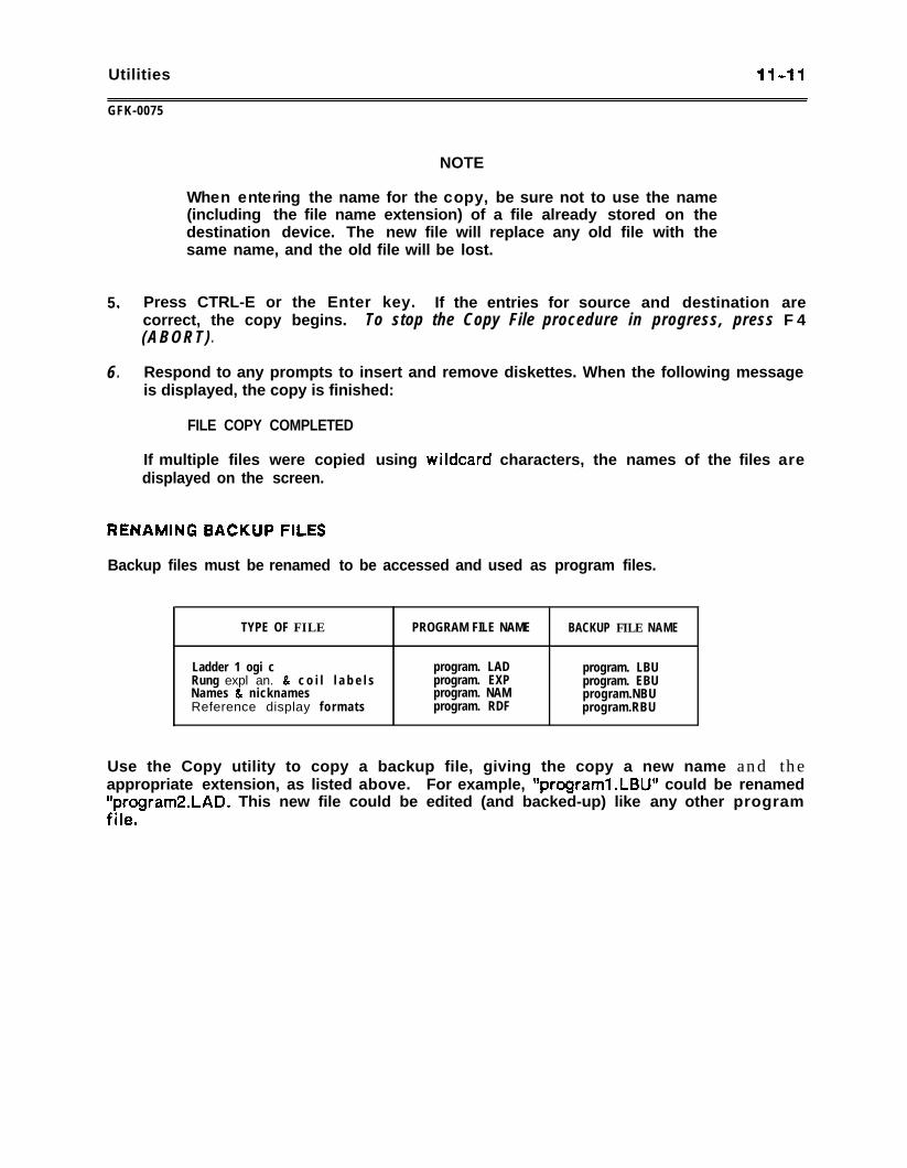
Utilities 11-11
GFK-0075
NOTE
When entering the name for the copy, be sure not to use the name(including the file name extension) of a file already stored on thedestination device. The new file will replace any old file with thesame name, and the old file will be lost.
5 . Press CTRL-E or the Enter key. If the entries for source and destination arecorrect, the copy begins.(ABORT)
To stop the Copy File procedure in progress, press F 4.
6 . Respond to any prompts to insert and remove diskettes. When the following messageis displayed, the copy is finished:
FILE COPY COMPLETED
If multiple files were copied using wildcard characters, the names of the files aredisplayed on the screen.
Backup files must be renamed to be accessed and used as program files.
TYPE OF FILE PROGRAM FILE NAME BACKUP FILE NAME
Ladder 1 ogi cRung expl an. & c o i l l a b e l sNames & nicknamesReference display formats
program. LADprogram. EXPprogram. NAMprogram. RDF
program. LBUprogram. EBUprogram.NBUprogram.RBU
Use the Copy utility to copy a backup file, giving the copy a new name and theappropriate extension, as listed above. For example, f’programl.LBUfV could be renamed“program2.LAD. This new file could be edited (and backed-up) like any other program
.file .
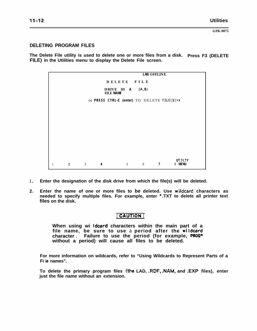
1142 Utilities
GFK-0075
DELETING PROGRAM FILES
The Delete File utility is used to delete one or more files from a disk. Press F3 (DELETEFILE) in the Utilities menu to display the Delete File screen.
L/M: OFFLINE
D E L E T E F I L E
DRIVE ID A (A,WFILE NAME
xc PRESS CTRL-E (enter) TO DELETE FILE(S) >>
UTILTY1 2 3 4 5 6 7 8 MENU
1 . Enter the designation of the disk drive from which the file(s) will be deleted.
2 . Enter the name of one or more files to be deleted. Use wildcard characters asneeded to specify multiple files. For example, enter * .TXT to delete all printer textfiles on the disk.
When using wi ldcard characters within the main part of afile name, be sure to use a period after the wildcardcharacter l Failure to use the period (for example, PROG*without a period) will cause all files to be deleted.
For more information on wildcards, refer to “Using Wildcards to Represent Parts of aFi le names”.
To delete the primary program files (the LAD, .RDF, .NAM, and .EXP files), enterjust the file name without an extension.
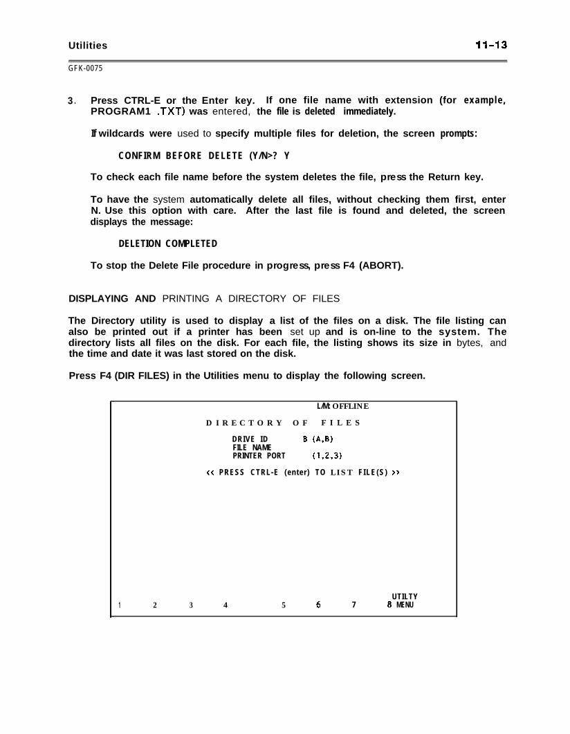
Utilities 1143
GFK-0075
3 . Press CTRL-E or the Enter key. If one file name with extension (for example,PROGRAM1 .TXT) was entered, the file is deleted immediately.
If wildcards were used to specify multiple files for deletion, the screen prompts:
CONFIRM BEFORE DELETE (Y/N>? Y
To check each file name before the system deletes the file, press the Return key.
To have the system automatically delete all files, without checking them first, enterN. Use this option with care. After the last file is found and deleted, the screendisplays the message:
DELETION COMPLETED
To stop the Delete File procedure in progress, press F4 (ABORT).
DISPLAYING AND PRINTING A DIRECTORY OF FILES
The Directory utility is used to display a list of the files on a disk. The file listing canalso be printed out if a printer has been set up and is on-line to the system. Thedirectory lists all files on the disk. For each file, the listing shows its size in bytes, andthe time and date it was last stored on the disk.
Press F4 (DIR FILES) in the Utilities menu to display the following screen.
L/M: OFFLINE
D I R E C T O R Y O F F I L E S
DRIVE ID B (&WFILE NAMEPRINTER PORT (1,&W
<< PRESS CTRL-E (enter) TO L I S T FILE(S) >>
UTILTY1 2 3 4 5 6 7 8 MENU
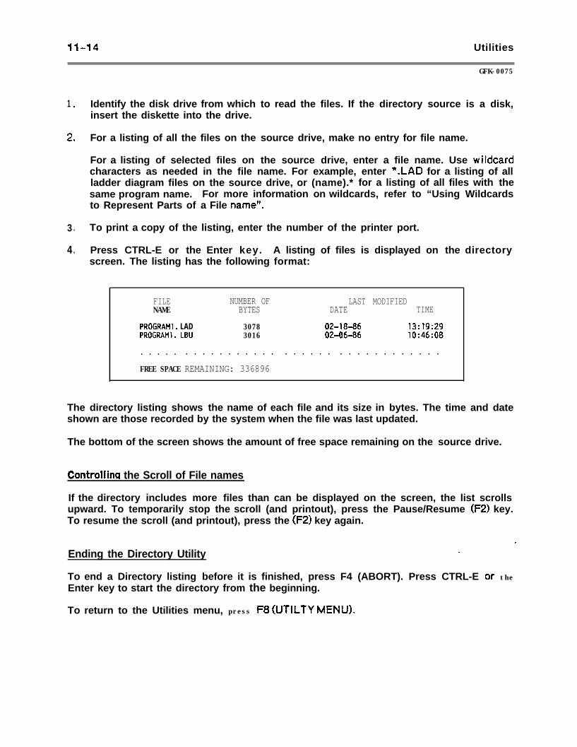
11-14 Utilities
1 .
2 .
3 .
4 .
Identify the disk drive from whichinsert the diskette into the drive.
to read the files. If the directory source is a disk,
For a listing of all the files on the ,! ,source drive, make no entry for file name.
For a listing of selected files on the source drive, enter a file name. Use wildcardcharacters as needed in the file name. For example, enter *.LAD for a listing of allladder diagram files on the source drive, or (name).* for a listing of all files with thesame program name. For more information on wildcards, refer to “Using Wildcardsto Represent Parts of a File name”.
GFK-0075
To print a copy of the listing, enter the number of the printer port.
Press CTRL-E or the Enter key. A listing of files is displayed on the directoryscreen. The listing has the following format:
,
FILENAME
PROGRAMl. LADPROGRAMl. LBU
NUMBER OF LAST MODIFIEDBYTES DATE TIME
3078 02-18-86 13:19:293016 02-0646 10:46:08
. . . . . . . . . . . . . . . . . . . . . . . . . . . . . . . . . .
FREE SPACE REMAINING: 336896
The directory listing shows the name of each file and its size in bytes. The time and dateshown are those recorded by the system when the file was last updated.
The bottom of the screen shows the amount of free space remaining on the source drive.
Controllincl the Scroll of File names
If the directory includes more files than can be displayed on the screen, the list scrollsupward. To temporarily stop the scroll (and printout), press the Pause/Resume (F2) key.To resume the scroll (and printout), press the (F2) key again.
Ending the Directory Utility.
_
To end a Directory listing before it is finished, press F4 (ABORT). Press CTRL-E or theEnter key to start the directory from the beginning.
To return to the Utilities menu, press F8 WTILTY MEW).
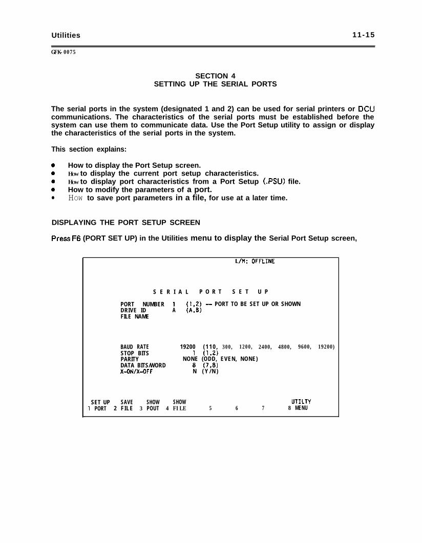
Utilities 11-15
GFK-0075
SECTION 4SETTING UP THE SERIAL PORTS
The serial ports in the system (designated 1 and 2) can be used for serial printers or DCUcommunications. The characteristics of the serial ports must be established before thesystem can use them to communicate data. Use the Port Setup utility to assign or displaythe characteristics of the serial ports in the system.
This section explains:
0 How to display the Port Setup screen.0 HOW to display the current port setup characteristics.0 HOW to display port characteristics from a Port Setup (.PSU) file.0 How to modify the parameters of a port. Il HOW to save port parameters in a file, for use at a later time.
DISPLAYING THE PORT SETUP SCREEN
Press F6 (PORT SET UP) in the Utilities menu to display the Serial Port Setup screen,
S E R I A L P O R T S E T U P
PORT NUMBER 1 (192) - PORT TO BE SET UP OR SHOWNDRIVE ID A (A,B)FILE NAME
BAUD RATE 19200 ( 1 1 0 , 300, 1200, 2400, 4800, 9600, 19200)STOP BITS 1 (1,2)PARITY NONE (ODD, EVEN, NONE)DATA BITS/WORD 8 (73)X-ON/X-OFF N ( Y / N )
SET UP SAVE SHOW SHOW UTILTY1 PORT 2 FILE 3 POUT 4 FILE 5 6 7 8 MENU
11-16 Utilities
UK-0075
PORT SETUP SCREEN KEY SUMMARY
The screen shows the characteristics for a port. The bottom of the screen shows thesefunction key assignments:
SET UP PORT (Fl) Use Fl to implement the parameters.
SAVE FILE (F2) Use F2 to create a Port Set Up file.
SHOW PORT (F3) Use F3 to display present port parameters.
SHOW FILE (F4) Use F4 to display port parameters from a file.
DISPLAYING THE CURRENT PARAMETERS FOR A PORT
To determine the current settings for one of the serial ports, enter the number of theport (1 or 2) for PORT NUMBER and press F3 (SHOW PORT).
DISPLAYING PARAMETERS IN A PORT SETUP FILE
Port Set Up values may be stored in a program file with the file name extension .PSU. Todetermine the current values stored in a Port Set Up file:
1 . Enter the drive where the file is stored for DRIVE ID.
2 . Enter the name of the file for FILE NAME.
3 . Press F4 (SHOW FILE). The current set up characteristics of the file are displayed.
SETTING UP PORT PARAMETERS
Serial port characteristics can be set up for current use only, or they can be stored in afile and loaded into the system each time it is powered up. Follow the steps below to setup the software to communicate over a serial port. If the port is being used forcommunication with the Data Communications (DCU), the parameters set up must matchthose of the DCU. It is also necessary to configure the hardware, as described inappendix A.
1 . Enter the following information about the device that will be using the serial port:
Baud Rate The communications rate, in bits per second.
Stop Bits All mmmwnications use one start bit. Slower devices may usetwo &p bits.
Par i ty An ASCII character may consist of either seven or eight databits. Specify whether parity is indicated by an odd or evennumber of bits, or whether no parity bit is added to the word.
Utilities I I - 1 7
GFK-0075
2 .
3 .
4 .
5 .
6 .
Data Bits
X-On/X-Off
Specify whether the device recognizes 7 or 8 bit words.
Change this entry to Y if you want to select Level 2 protocol.Level 2 protocol allows the device connected to the serialport to suspend or restart transmission of characters using theX-ON and X-OFF characters. When the system receives anX-OFF character (DC343H) from the device, it stopstransmitting characters. When the system then receives anX-ON (DCl-11 H) character, transmission resumes.
The X-OFF character must be sent by the device before thereception of the last data bit of the current character beingsent to the system, or the next character will also be sent.
If X-ON/X-OFF protocol is used with a device that does notsupport hardware handshaking, the hardware lines DTR-DSRand RTS-CTS must be tied together (pins 4-5 and 6-9 on theg-pin port).
Enter the number of the serial port being set up.
If this setup will be stored in a file for use in future start up, proceed with steps 4-6.
If this setup is intended only until power is removed from the system, or until newsetup information is entered, press Fl (SET UP PORT) to execute the setup.
If this setup will be stored in a file, place the Logicmaster 1 F system diskette in adisk drive, and enter the letter designation of the drive. The set up file will bewritten to the diskette, so remove any write-protection from the diskettetemporarily. If storing to a hard disk, the file will be stored in the \LlF subdirectory.
Enter the file name PORT1 .PSU or PORTZ.PSU, depending on whether you aresetting up port 1 or 2. Note: the five may be stored as any file name.PSU, but mustbe renamed to either PORTIPSU or PORT Z.PSU, depending on whether you want toset up port 1 or port 2 automatically at power-up.
Press F2 (SAVE FILE). The setup file will be placed on the Logicmaster 1 F systemdiskette. However, the setup information in the file will not be used until the file isloaded into programmer memory during the next power up. To activate the set upduring the current session, press the Set Up Port (Fl) key to execute the setup.

Programming 12-l
GFK-0075
CHAPTER 12PROGRAMMING
The first eleven chapters of this manual describe the features and use of Logicmaster 1 Fsoftware.
Chapters 12 and 13 are about programming the Series One (Model E) and Series One PiusPLC. . Chapter 12 presents general programming concepts and describes basicprogramming instructions. Chapter 13 describes data operation instructions, which areavailable only with the Series One Plus PLC.
This chapter consists of the following sections:
Section I. Ladder Logic Programs: Section 1 describes the CPU scan, the format of aprogram, elements of a program, and program references.
Section 2. Programming Instructions: Section 2 describes basic programminginstructions available for the Series One Wdel E) and Series One Plus PLC. (Refer toChapter 13 for Data Operation instructions for the Series One Plus PLC.)
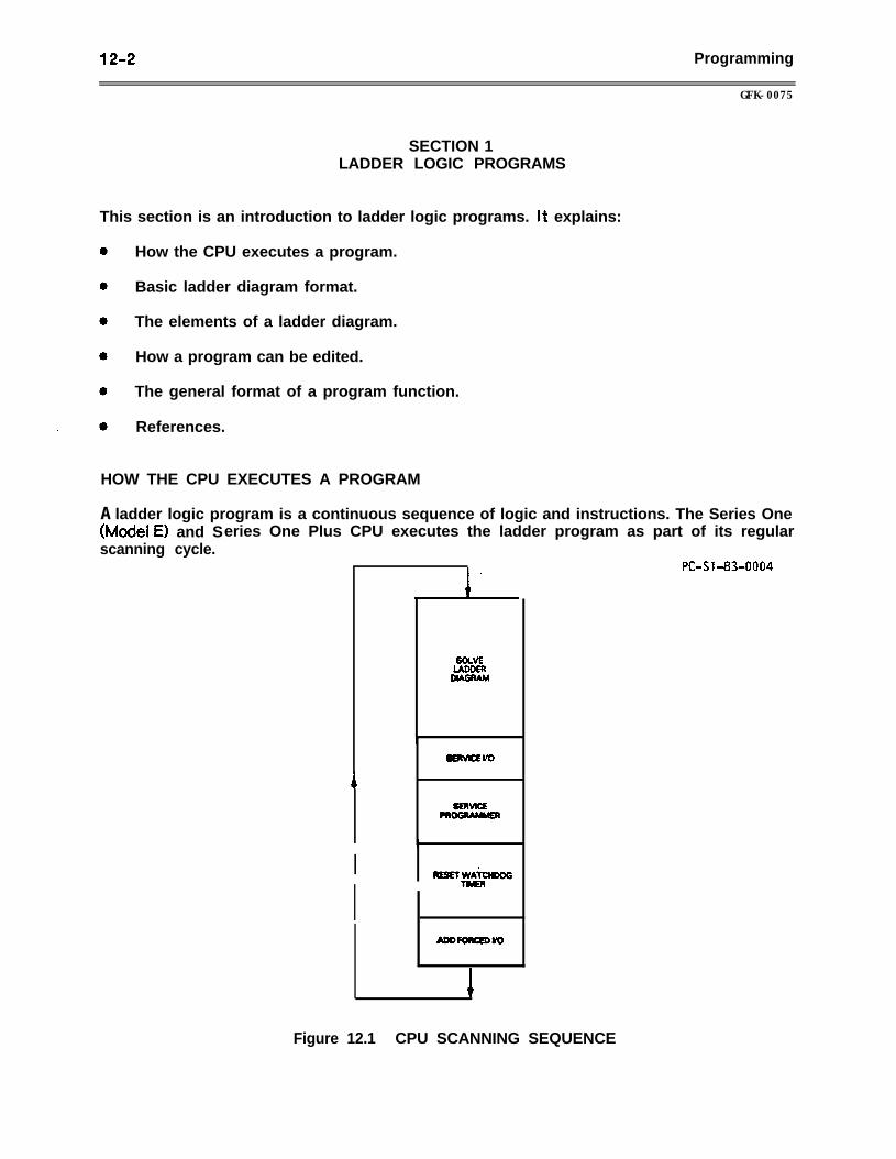
12-2 Programming
GFK-0075
SECTION 1LADDER LOGIC PROGRAMS
This section is an introduction to ladder logic programs. It explains:
How the CPU executes a program.
Basic ladder diagram format.
The elements of a ladder diagram.
How a program can be edited.
The general format of a program function.
References.
HOW THE CPU EXECUTES A PROGRAM
A ladder logic program is a continuous sequence of logic and instructions. The Series One0vlodeI E) and Series One Plus CPU executes the ladder program as part of its regularscanning cycle.
SOLVEUDDER
#AGRAM
Figure 12.1 CPU SCANNING SEQUENCE
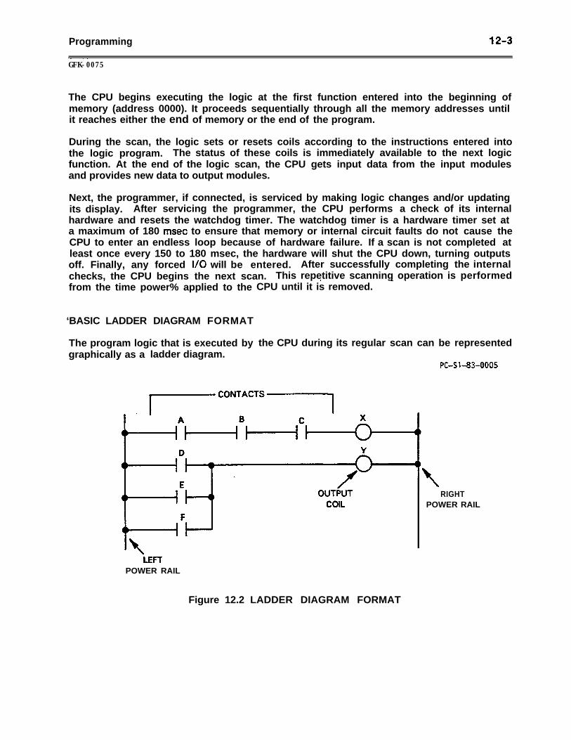
Programming 12-3~~GFK-0075
The CPU begins executing the logic at the first function entered into the beginning ofmemory (address 0000). It proceeds sequentially through all the memory addresses untilit reaches either the end of memory or the end of the program.
During the scan, the logic sets or resets coils according to the instructions entered intothe logic program. The status of these coils is immediately available to the next logicfunction. At the end of the logic scan, the CPU gets input data from the input modulesand provides new data to output modules.
Next, the programmer, if connected, is serviced by making logic changes and/or updatingits display. After servicing the programmer, the CPU performs a check of its internalhardware and resets the watchdog timer. The watchdog timer is a hardware timer set ata maximum of 180 msec to ensure that memory or internal circuit faults do not cause theCPU to enter an endless loop because of hardware failure. If a scan is not completed atleast once every 150 to 180 msec, the hardware will shut the CPU down, turning outputsoff. Finally, any forced I/O will be entered. After successfully completing the internalchecks, the CPU begins the next scan. This repetitive scanning operation is performed*
- -from the time power% applied to the CPU until it is removed.
‘BASIC LADDER DIAGRAM FORMAT
The program logic that is executed by the CPU during its regular scan can be representedgraphically as a ladder diagram.
PC-s1-83-0005
HHdY
LEFTPOWER RAIL
RIGHTPOWER RAIL
Figure 12.2 LADDER DIAGRAM FORMAT
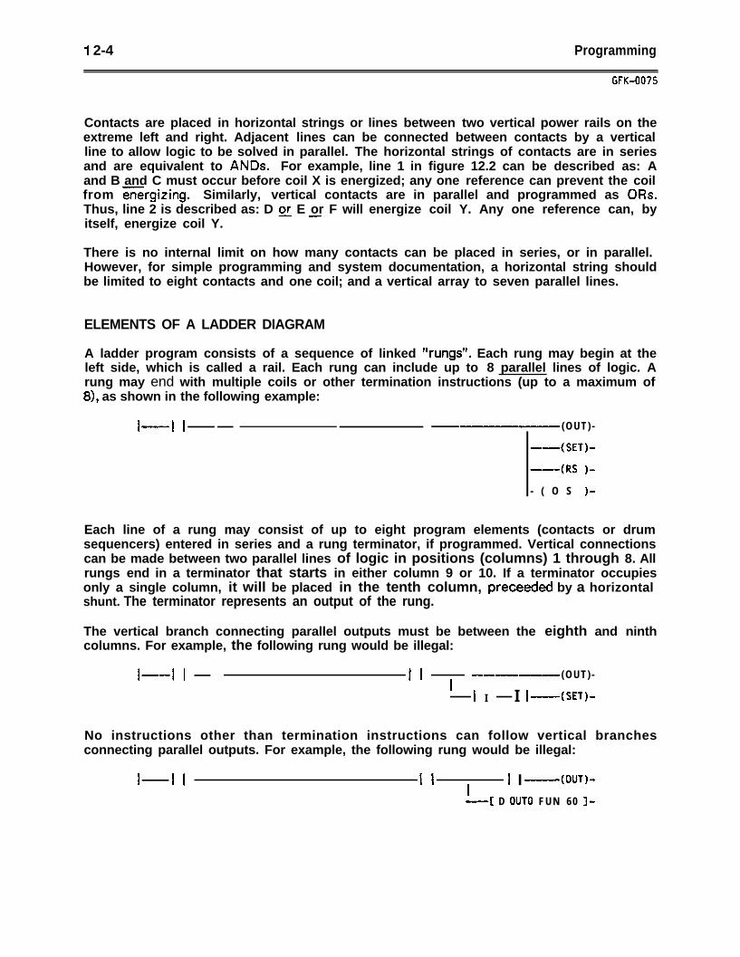
I 2-4 Programming
GfK-007s
Contacts are placed in horizontal strings or lines between two vertical power rails on theextreme left and right. Adjacent lines can be connected between contacts by a verticalline to allow logic to be solved in parallel. The horizontal strings of contacts are in seriesand are equivalent to ANDs. For example, line 1 in figure 12.2 can be described as: Aand B and C must occur before coil X is energized; any one reference can prevent the coilfrom GGkgizing. Similarly, vertical contacts are in parallel and programmed as ORs.Thus, line 2 is described as: D E or F will energize coil Y. Any one reference can, byitself, energize coil Y.
There is no internal limit on how many contacts can be placed in series, or in parallel.However, for simple programming and system documentation, a horizontal string shouldbe limited to eight contacts and one coil; and a vertical array to seven parallel lines.
ELEMENTS OF A LADDER DIAGRAM
A ladder program consists of a sequence of linked “rungs”. Each rung may begin at theleft side, which is called a rail. Each rung can include up to 8 parallel lines of logic. Arung may end with multiple coils or other termination instructions (up to a maximum of8), as shown in the following example:
1-- I I -m-m, (OUT) -
--(SET)-
-(RS )-
- ( O S )-
Each line of a rung may consist of up to eight program elements (contacts or drumsequencers) entered in series and a rung terminator, if programmed. Vertical connectionscan be made between two parallel lines of logic in positions (columns) 1 through 8. Allrungs end in a terminator that starts in either column 9 or 10. If a terminator occupiesonly a single column, it will be placed in the tenth column, preceeded by a horizontalshunt. The terminator represents an output of the rung.
The vertical branch connecting parallel outputs must be between the eighth and ninthcolumns. For example, the following rung would be illegal:
I--l I I I w--p
I(OUT) -
I I I I -(SET)-
No instructions other than termination instructions can follow vertical branchesconnecting parallel outputs. For example, the following rung would be illegal:
I I I I II
I I-(OUT)-
-4 D OUT0 FUN 60 J-
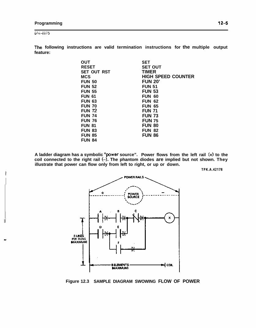
Programming 12-s
The following instructions are valid termination instructions for the multiple outputfeature:
OUTRESETSET OUT RSTMCSFUN 50FUN 52FUN 55FUN 61FUN 63FUN 70FUN 7iFUN 74FUN 76FUN 81FUN 83FUN 85FUN 84
SETSET OUTTIMERHIGH SPEED COUNTERFUN 20’FUN 51FUN 53FUN 60FUN 62FUN 65FUN 71FUN 73FUN 75FUN 80FUN 82FUN 86
A ladder diagram has a symbolic “power source”. Power flows from the left rail (+) to thecoil connected to the right rail (-). The phantom diodes are implied but not shown. Theyillustrate that power can flow only from left to right, or up or down.
TPK.A.42178
8 UN&PfR RUNG
MAXIMUM)
Figure 12.3 SAMPLE DIAGRAM SWOWING FLOW OF POWER
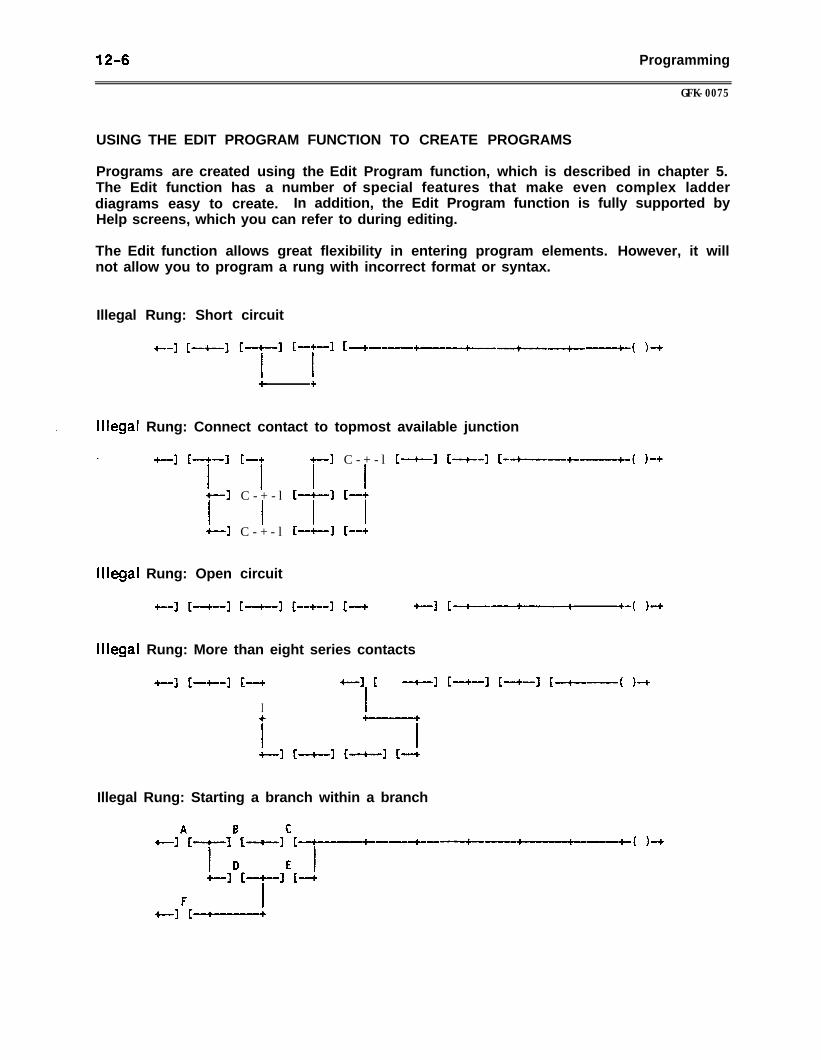
12-6 Programming
GFK-0075
USING THE EDIT PROGRAM FUNCTION TO CREATE PROGRAMS
Programs are created using the Edit Program function, which is described in chapter 5.The Edit function has a number of special features that make even complex ladderdiagrams easy to create. In addition, the Edit Program function is fully supported byHelp screens, which you can refer to during editing.
The Edit function allows great flexibility in entering program elements. However, it willnot allow you to program a rung with incorrect format or syntax.
Illegal Rung: Short circuit
t-1 [4--J [-+-I I-+-l [:aB+-~-+--4-----c-------+--
I I
-4( k+
lllega
lllega
Rung: Connect contact to topmost available junction
+-I IT’ 7+--I C - + - l
I I+-I C - + - l
+-I
IF-+-l
I++-I
C - + - l C-+--l
II-+
II-+
[4-3 [-+--+---4-( )-+
Rung: Open circuit
+-I 1-+-I k-+-l k+-1 I-+ +-I c-+-- +-( )-+
Rung: More than eight series contacts
+--1 [-+--I [4
I
+-II:
I
-+-I [-+-] [4-3 [-+----( )4
Illegal Rung: Starting a branch within a branch
A B c+-I I-+-I I
I-4-l [--I----+----+-----+---I---4-( )4
D E I+-I f-+-l I-+
F I+-] [-+----+
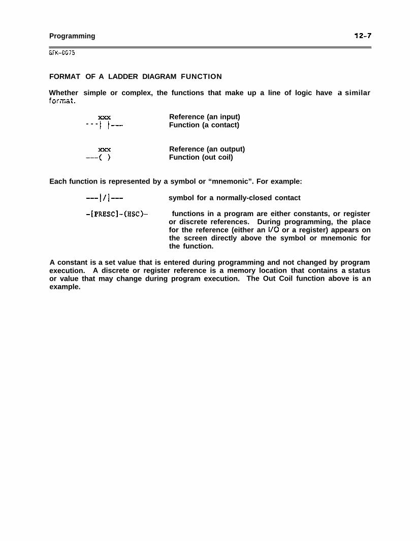
Programming
i;FK-CG75
12-7
FORMAT OF A LADDER DIAGRAM FUNCTION
Whether simple or complex, the functions that make up a line of logic have a similarL:I Omk.
Reference (an input)- - - l I W-B Function (a contact)
Reference (an output)Function (out coil)
Each function is represented by a symbol or “mnemonic”. For example:
--- 14 w-c symbol for a normally-closed contact
-[PRESC]-@SC)- functions in a program are either constants, or registeror discrete references. During programming, the placefor the reference (either an l/O or a register) appears onthe screen directly above the symbol or mnemonic forthe function.
A constant is a set value that is entered during programming and not changed by programexecution. A discrete or register reference is a memory location that contains a statusor value that may change during program execution. The Out Coil function above is anexample.
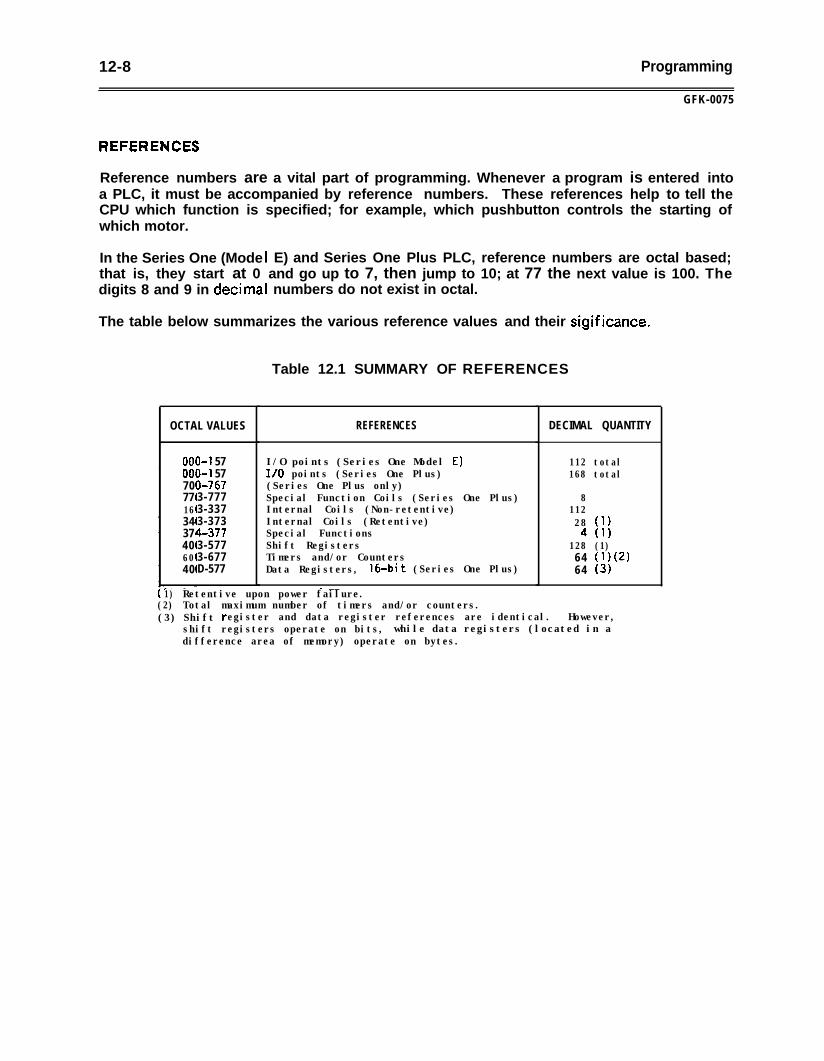
12-8 Programming
GFK-0075
Reference numbers are a vital part of programming. Whenever a program is entered intoa PLC, it must be accompanied by reference numbers. These references help to tell theCPU which function is specified; for example, which pushbutton controls the starting ofwhich motor.
In the Series One (Mode Ithat is, they start at 0digits 8 and 9 in decima I
E) and Series One Plus PLC, reference numbers are octal based;and go up to 7, then jump to 10; at 77 the next value is 100. Thenumbers do not exist in octal.
The table below summarizes the various reference values and their sigificance.
Table 12.1 SUMMARY OF REFERENCES
OCTAL VALUES REFERENCES DECIMAL QUANTITY
00007077163437406040
3-l 573-l 57l-7673-7773-3373-373q-3773-5773-677D-577
I/O points (Series One Model E)I/O points (Series One Plus)(Series One Plus only)Special Function Coils (Series One Plus)Internal Coils (Non-retentive)Internal Coils (Retentive)Special FunctionsShift RegistersTimers and/or CountersData Registers, 160bit (Series One Plus)
- __1) Retentive upon power failure.
(2) Total maximum number of timers and/or counters.
112 total168 total
811228 (1)4 (1)
128 (1)64 W(2)64 (3)
(3) Shift register and data register references are identical. However,shift registers operate on bits, while data registers (located in adifference area of memory) operate on bytes.
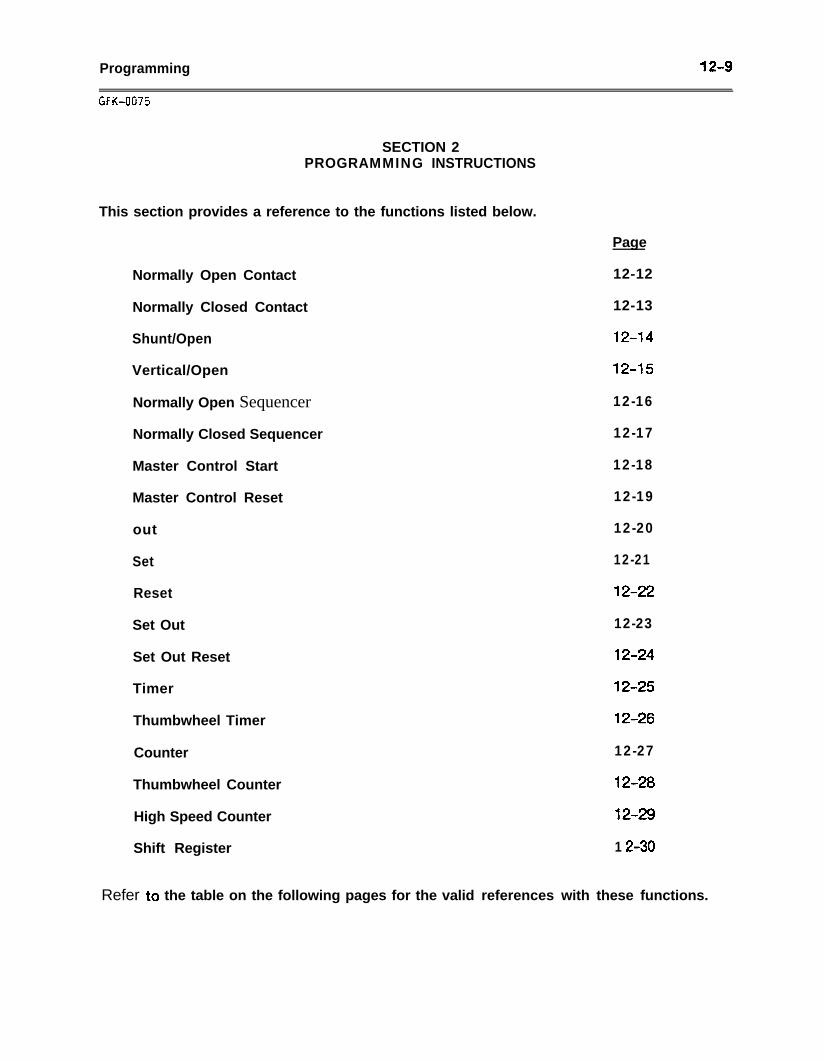
Programming 12-9
SECTION 2PROGRAMMING INSTRUCTIONS
This section provides a reference to the functions listed below.
Normally Open Contact
Normally Closed Contact
Shunt/Open
Vertical/Open
Normally Open Sequencer
Normally Closed Sequencer
Master Control Start
Master Control Reset
out
Set
Reset
Set Out
Set Out Reset
Timer
Thumbwheel Timer
Counter
Thumbwheel Counter
High Speed Counter
Shift Register
Page
12-12
12-13
12-14
12-15
12-16
12-17
12-18
12-19
12-20
12-21
12-22
12-23
12-24
12-25
12-26
12-27
12-28
1249
1 Z-30
Refer to the table on the following pages for the valid references with these functions.
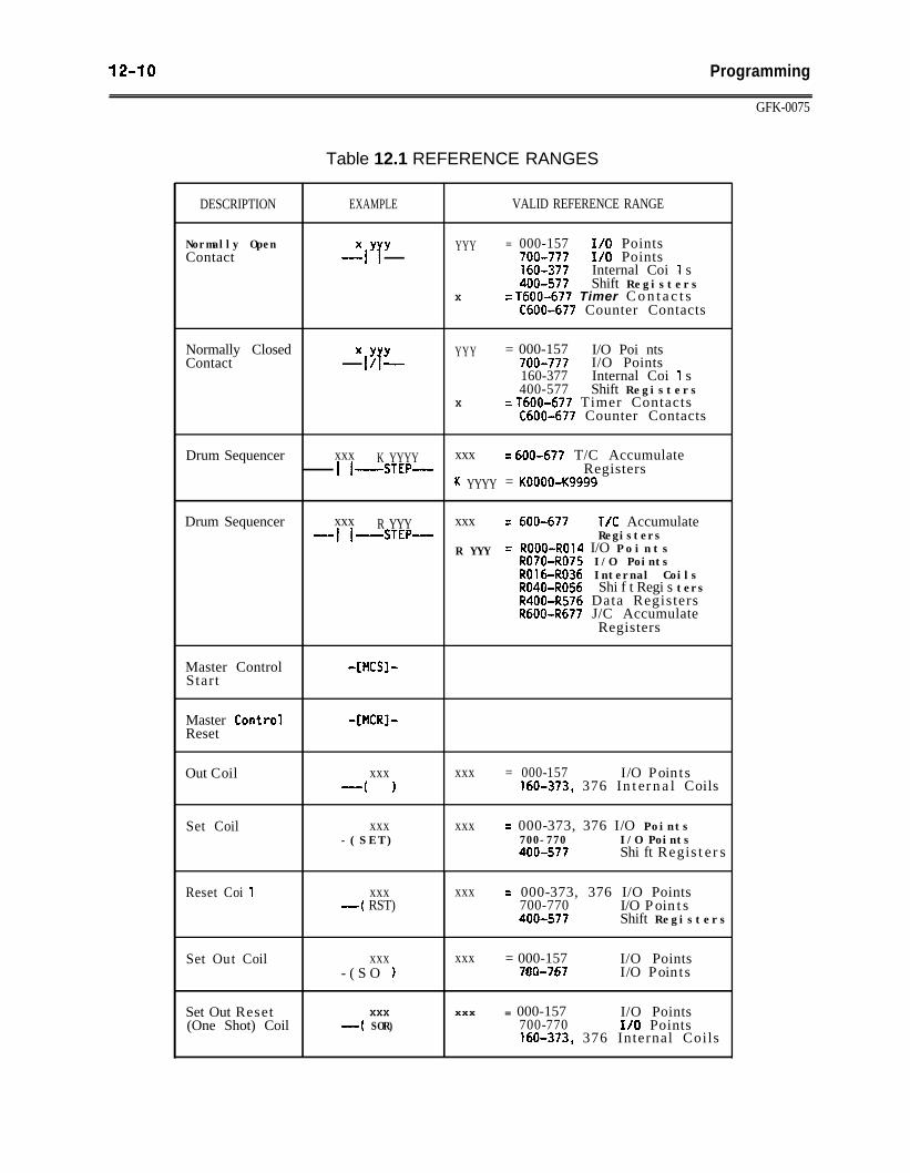
12-10 Programming
GFK-0075
Table 12.1 REFERENCE RANGES
DESCRIPTION EXAMPLE VALID REFERENCE RANGE
Normally OpenContact
XYY-I T
YYY = 000-157 I/O Points700-777 I/O Points160-377 Internal Coi 1 s400-577 Shift Registers
X = T600-677 Timer C o n t a c t sC600-677 Counter Contacts
Normally ClosedContact
XYYI&-
YYY = 000-157 I/O Poi nts700-777 I/O Points160-377 Internal Coi 1 s400-577 Shift Registers
X = T600-677 Timer ContactsC600-677 Counter Contacts
Drum Sequencer xxx K YYYY xxx = 600-677 T/C AccumulateI I -STEP- Registers
K YYYY = KOOOO-Kg999
Drum Sequencer xxx xxx = 600-677-I I
R YYY T/C Accumulate-STEP- Registers
R YYY = ROOO-R014 I/O P o i n t sR070-R075 I/O PointsR016-R036 Internal CoilsR040-R056 Shi f t Regi s tersR400-R576 Data RegistersRdOO-R677 J/C Accumulate
Registers
Master ControlStart
-[?lCS]-
Master Contro’lReset
Out Coil
Set Coil
Reset Coi 1
Set Out Coil
Set Out Reset(One Shot) Coil
-[MCRJ-
xxx-( 1
xxx- ( S E T )
xxx-( RST)
xxx- ( S O 1
XXX
-( SOR)
xxx
xxx
xxx
xxx
xxx
= 000-157 I/O Points160-373, 376 Internal Coils
= 000-373, 376 I/O Points700-770 I/O Points400-577 Shi ft Registers
= 000-373, 376 I/O Points700-770 I/O Points400-577 Shift Registers
= 000-157 I/O Points700-767 I/O Points
= 000-157 I/O Points700-770 I/O Points160-373, 376 Internal Coils
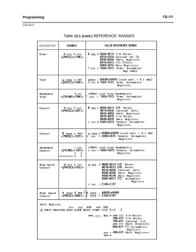
Programming 12-11
GFK-0075
Table 12.1 (cont.) REFERENCE RANGES
DESCRIPTION EXAMPLE VALIi REFERENCE RANGE
Timer R yyy T xxx R YYY = ROOO-ROl4 I/O Points-[PRESC]-(TMR)- R016-R036 Internal Coi 1s
R040-R056 Shift RegistersR070-R075 I/O PointsR400-R576 Data Registers
1 xxx = T600-T673 Timer AccumulateRegi stem
Timer K YYYY T xxx KYYYY = KOOOO-Kg999 (each unit = 0.1 set)-[PRESC]-(TMR)- T xxx = T600-T673 Timer Accumulate
Registers
Thumbwheel T xxx (PRESC read from thumbwheels)Timer -[TH/WH]-(TMR)- 1 xxx = T600-T673 Timer Accumulate
Registers
Counter R yyy C xxx R YYY = ROOU-R014 I/O Points-[PRESC]-(CNT)- R016-R036 Internal Coils
R040-R056 Shift RegistersR070-R075 I/O PointsR400-R576 Data Registers
c xxx = C600-C673 Counter AccumulateRegisters .
Counter K YYYY C xxx K YYYY = KOOOO-Kg999 (each unit = 0.1 set-[PRESC]-(CNT)- C xxx = C600-C673 Counter Accumulate
Registers
Thumbwheel c xxx (PRESC read from thumbwheels)Counter -[TH/WH]-( CNT)- c xxx = C600-C673 Counter Accumulate
( 1 Registers( 1
High Speed R yyy C xxx R YYY = ROOO-R014 I/O PointsCounter -[PRESC]-(HSC)- R070-R075 I/O Points
R016-R036 Internal CoilsR040-R056 Shift RegistersR400-R576 Data RegistersRdOO-R677 T/C Accumulate
Registersc xxx = Cl009Cl07
High Speed ' K YYYY f xxx ' K YYYY = KOOOO-Kg999Counter -[PRESC]-(HSC)- C x x x = C100-Cl07
Shift Registerxxx YYY zzz aaa bbb
-[ SHIFT REGISTER DATA CLOCK RESET START STOP 1-t )
xxx, yyy, 222 = 000-157 I/O Points700-777 I/O Points160-377 Internal I/O400-577 Shift Registers600-677 T/C Accumulate
Registersaaa = 400-577 Shift Registersbbb =
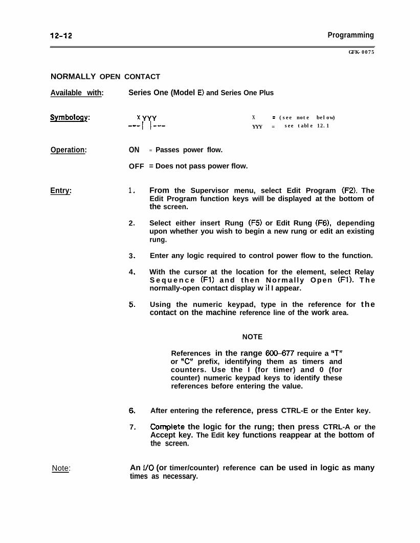
12-12 Programming
GFK-0075
NORMALLY OPEN CONTACT
Available with: Series One (Model E) and Series One Plus
Symbology:
Operation:
x YYYIM-w I
ON
OFF
X = (see note below)
I em- YYY = see table 12.1
Entry: 1 .
2 .
3 .
4 .
5 .
6‘0
7 .
Note:
= Passes power flow.
= Does not pass power flow.
From the Supervisor menu, select Edit Program (F2). TheEdit Program function keys will be displayed at the bottom ofthe screen.
Select either insert Rung (F5) or Edit Rung (F6), dependingupon whether you wish to begin a new rung or edit an existingrung.
Enter any logic required to control power flow to the function.
With the cursor at the location for the element, select RelayS e q u e n c e (Fl) and then Normal ly Open (Fl). T h enormally-open contact display w il I appear.
Using the numeric keypad, type in the reference for thecontact on the machine reference line of the work area.
NOTE
References in the range 600-677 require a “TIror V prefix, identifying them as timers andcounters. Use the I (for timer) and 0 (forcounter) numeric keypad keys to identify thesereferences before entering the value.
After entering the reference, press CTRL-E or the Enter key.
Comp!ete the logic for the rung; then press CTRL-A or theAccept key. The Edit key functions reappear at the bottom ofthe screen.
An I/O (or timer/counter) reference can be used in logic as manytimes as necessary.
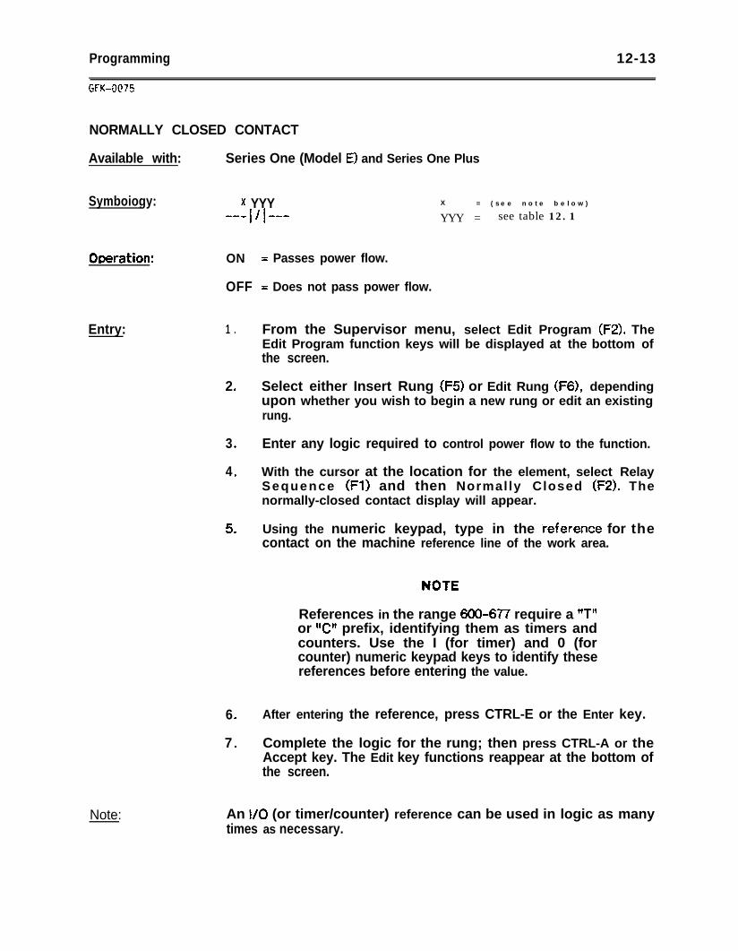
Programming 12-13
NORMALLY CLOSED CONTACT
Available with: Series One (Model E) and Series One Plus
Symboiogy: * YYY X = ( s e e n o t e b e l o w )
B-WVI
W-W YYY = see table 12.1
ODeration: ON
OFF = Does not pass power flow.
Entry: 1 .
Note:
2 .
3 .
4 .
5 .
6 .
7 .
= Passes power flow.
From the Supervisor menu, select Edit Program (FZ). TheEdit Program function keys will be displayed at the bottom ofthe screen.
Select either Insert Rung (F5) or Edit Rung (F6), dependingupon whether you wish to begin a new rung or edit an existingrung.
Enter any logic required to control power flow to the function.
With the cursor at the location for the element, select RelaySequence (Fl) and then Normally Closed (FZ). Thenormally-closed contact display will appear.
Using the numeric keypad, type in the ieference for thecontact on the machine reference line of the work area.
References in the range 600-677 require a ITT”or V’ prefix, identifying them as timers andcounters. Use the I (for timer) and 0 (forcounter) numeric keypad keys to identify thesereferences before entering the value.
After entering the reference, press CTRL-E or the Enter key.
Complete the logic for the rung; then press CTRL-A or theAccept key. The Edit key functions reappear at the bottom ofthe screen.
An l/O (or timer/counter) reference can be used in logic as manytimes as necessary.
12-14 Programming
SHUNT/OPEN
Available with: Series One (Model E) and Series One Pius
Symbology:
Operation:
Entry:
GFK-0075
SHUNT = Passes power flow.
OPEN = Does not pass power flow.
1 .
2 .
3 .
4 .
5 .
6 .
From the Supervisor menu, select Edit Program (F2). TheEdit Program functionkeys will be displayed at the bottom ofthe screen.
Select either Insert Rung (F5) or Edit Rung (F6), dependingupon whether you wish to begin a new rung or edit an existingrung l
Enter any logic required to control power flow to the function.
With the cursor at the location for the shunt, select RelaySequence (Fl) and then Shunt (F3). The shunt display appearsin the rung, and the cursor moves to the next column.
Shunt/Open (F3) can also be used to replace an existingelement or shunt already displayed in the rung. If you arereplacing an element, position the cursor at the location ofthe element and select Shunt (F3). The element will bereplaced by a shunt. If you are replacing a shunt, position thecursor at the Jocation of the shunt and select Open (F3). Theshunt will be deleted from the rung.
Complete the logic for the rung; then press CTRL-A or theAccept key. The Edit key functions reappear at the bottom ofthe screen.
Programming 1245
GFK-0075
VERT/OPEN
Available with: Series One (Model E) and Series One Plus
Symbology:
Operation:
Entry:
VERT = Passes power flow.
OPEN = Does not pass power flow.
1 l
2 l
3 .
4 .
5 .
6 .
From the Supervisor menu, select Edit Program (F2). TheEdit Program function keys will be displayed at the bottom ofthe screen.
Select either Insert Rung (F5) or Edit Rung (F6), dependingupon whether you wish to begin a new rung or edit an existingrung.
Enter any logic required to control power flow to the function.
With the cursor at the location for the element, select RelavSequence (Fl) and then Vertical (F4). A vertical connectoiwill appear in the rung.
Vertical (F4) can also be used to delete an existing verticalconnector in the rung. Position the cursor on the location ofthe existing connector, and then select Vertical/Open (F4).The connector will be deleted from the rung.
Complete the logic for the rung; then press CTRL-A or theAccept’key. The Edit key functions reappear at the bottom ofthe screen.
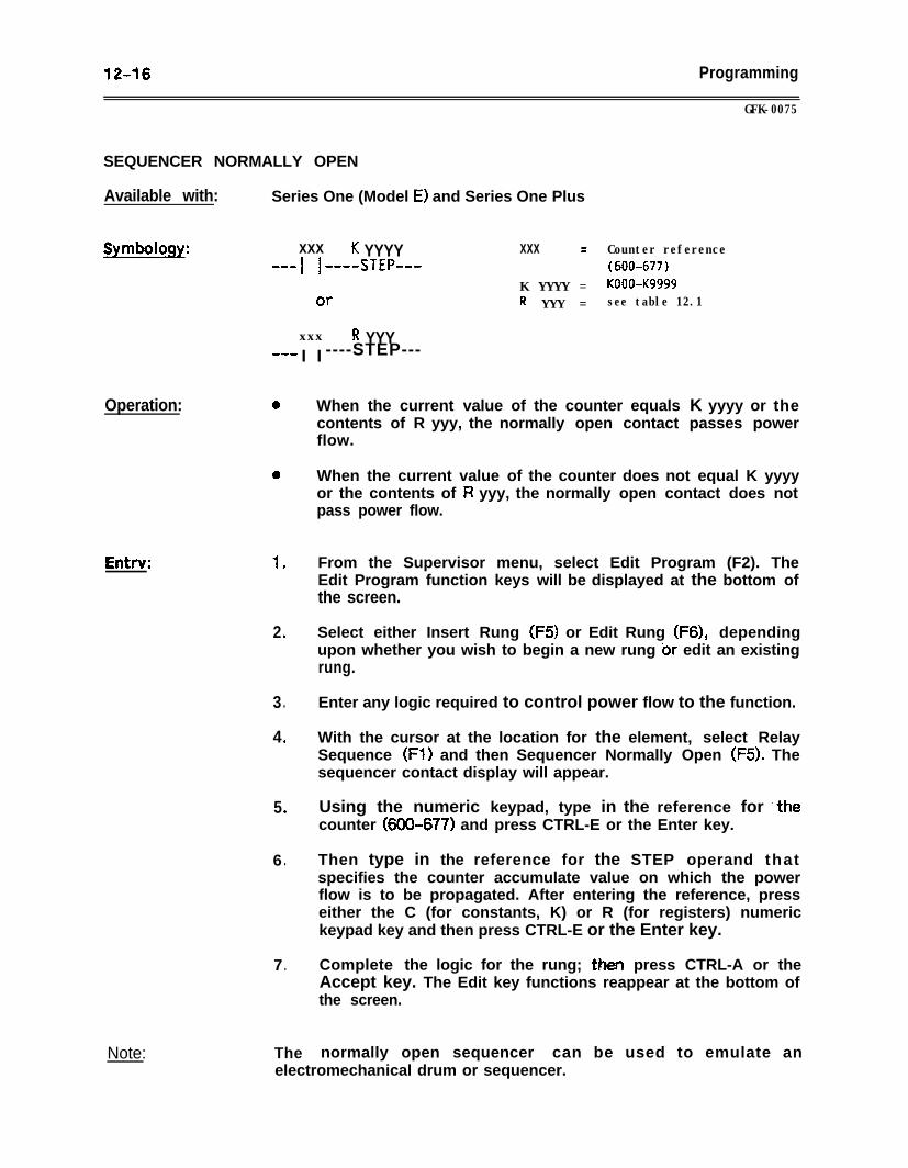
12-16 Programming
GFK-0075
SEQUENCER NORMALLY OPEN
Available with: Series One (Model E) and Series One Plus
Symboloqy: xxx K YYYY xxx = Counter referenceB-w I I ---STEP-_- (600-677)
K YYYY = KOOO-Kg999OT- R YYY = see table 12.1
xxx R YYY__I I I ----STEP---
Operation:
Entrv:
Note:
0 When the current value of the counter equals K yyyy or thecontents of R yyy, the normally open contact passes powerflow.
0 When the current value of the counter does not equal K yyyyor the contents of R yyy, the normally open contact does notpass power flow.
1 .
2 .
3 .
4 .
5 .
6 .
From the Supervisor menu, select Edit Program (F2). TheEdit Program function keys will be displayed at the bottom ofthe screen.
Select either Insert Rung (F5) or Edit Rung (F6), dependingupon whether you wish to begin a new rung br edit an existingrung.
Enter any logic required to control power flow to the function.
With the cursor at the location for the element, select RelaySequence (FI) and then Sequencer Normally Open (F5). Thesequencer contact display will appear.
Using the numeric keypad, type in the reference for ‘thecounter (600-677) and press CTRL-E or the Enter key.
Then type in the reference for the STEP operand thatspecifies the counter accumulate value on which the powerflow is to be propagated. After entering the reference, presseither the C (for constants, K) or R (for registers) numerickeypad key and then press CTRL-E or the Enter key.
7 . Complete the logic for the rung; then press CTRL-A or theAccept key. The Edit key functions reappear at the bottom ofthe screen.
The normally open sequencer can be used to emulate anelectromechanical drum or sequencer.
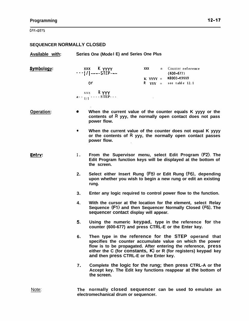
Programming 1247
GFG0075
SEQUENCER NORMALLY CLOSED
Available with: Series One (Mode
Symbology: xxx K YYYY- - - VI ----STEP-
Or
xxx R YYY_ _
Operation:
Entrv:
Note:
I E) and Series One Plus
xxx = Counter reference(600-677)
K YYYY = KOOOO-Kg999R YYY = see table 12.1
a-- l/l ----STEP--- ,
0 When the current value of the counter equals K yyyy or thecontents of R yyy, the normally open contact does not passpower flow.
l When the current value of the counter does not equal K yyyyor the contents of R yyy, the normally open contact passespower flow. ,
1 .
2 .
3 .
4 .
5 .
6 .
From the Supervisor menu, select Edit Program (F2). TheEdit Program function keys will be displayed at the bottom ofthe screen.
Select either Insert Rung (F5) or Edit Rung (F6), dependingupon whether you wish to begin a new rung or edit an existingrung.
Enter any logic required to control power flow to the function.
With the cursor at the location for the element, select RelaySequence (Fl) and then Sequencer Normally Closed (F6). Thesequencer contact display will appear.
Using the numeric keypad, type in the reference for thecounter (600-677) and press CTRL-E or the Enter key.
Then type in the reference for the STEP operand thatspecifies the counter accumulate value on which the powerflow is to be propagated. After entering the reference, presseither the C (for constants, K) or R (for registers) keypad keyand then press CTRL-E or the Enter key.
7 . Complete the logic for the rung; then press CTRL-A or theAccept key. The Edit key functions reappear at the bottom ofthe screen.
The normally closed sequencer can be used to emulate an
.
electromechanical drum or sequencer.
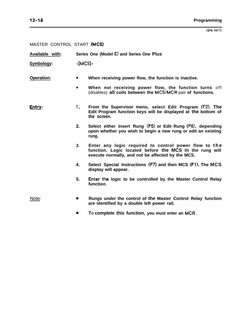
12-18 Programming
GFK-0075
MASTER CONTROL START (MCS)
Available with: Series One (Model E) and Series One Plus
Symbology: -[MCSl-
Operation: l
l
Entrv: 1 .
Note:
2 .
3 .
4 .
5 .
0
0
When receiving power flow, the function is inactive.
When not receiving power flow, the function turns of f(disables) all coils between the MCS/MCR pair of functions.
From the Supervisor menu, select Edit Program (FZ). TheEdit Program function keys will be displayed at the bottom ofthe screen.
Select either Insert Rung (FS) or Edit Rung (F6), dependingupon whether you wish to begin a new rung or edit an existingrung.
Enter any logic required to control power flow to t h efunction. Logic located before the MCS in the rung willexecute normally, and not be affected by the MCS.
Select Special Instructions (F7) and then MCS (Fl). The MCSdisptay will appear.
Enter’the logic to be controlled by the Master Control Relayfunction.
Rungs under the control of the Master Control Relay functionare identified by a double left power rail.
TO complete this function, you must enter an MCR.
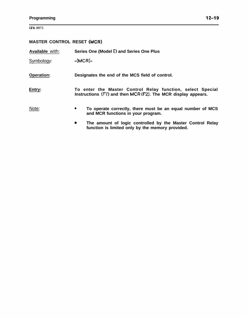
Programming 12-19
GFK-0075
MASTER CONTROL RESET (MCR)
Available with: Series One (Model E) and Series One Plus
Symbology: -[MCI?]-
Operation: Designates the end of the MCS field of control.
Entry: To enter the Master Control Relay function, select SpecialInstructions (F7) and then MCI3 (FZ). The MCR display appears.
Note: l To operate correctly, there must be an equal number of MCSand MCR functions in your program.
0 The amount of logic controlled by the Master Control Relayfunction is limited only by the memory provided.
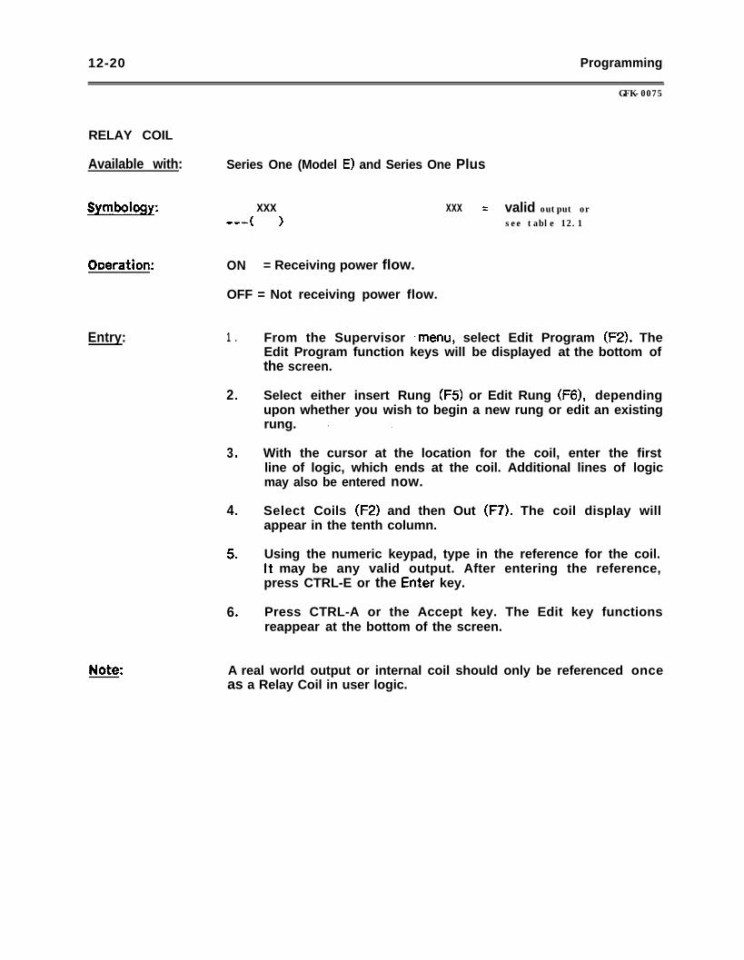
12-20 Programming
RELAY COIL
Available with: Series One (Model E) and Series One Plus
Symbology:
ODeration:
Entry:
GFK-0075
xxx xxx = valid output orw-w ( ) see table 12.1
ON = Receiving power flow.
OFF = Not receiving power flow.
1 .
2 .
3 .
4 .
5 .
6 .
From the Supervisor *menu, select Edit Program (FZ). TheEdit Program function keys will be displayed at the bottom ofthe screen.
Select either insert Rung (F5) or Edit Rung (F6), dependingupon whether you wish to begin a new rung or edit an existingrung. * .
With the cursor at the location for the coil, enter the firstline of logic, which ends at the coil. Additional lines of logicmay also be entered now.
Select Coils (F2) and then Out (F7). The coil display willappear in the tenth column.
Using the numeric keypad, type in the reference for the coil.It may be any valid output. After entering the reference,press CTRL-E or the Enter key.
Press CTRL-A or the Accept key. The Edit key functionsreappear at the bottom of the screen.
A real world output or internal coil should only be referenced onceas a Relay Coil in user logic.
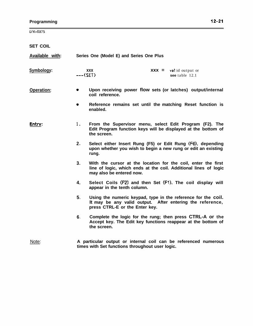
Programming 12-21
GFK-0075
SET COIL
Available with:
Symbology:
Series One (Model E) and Series One Plus
xxx xxx = val id output or---(SET) see table 12.1
Operation:
Entnc 1 .
Note:
2 .
3 .
4 .
5 .
6 .
Upon receiving power flow sets (or latches) output/internalcoil reference.
Reference remains set until the matching Reset function isenabled.
From the Supervisor menu, select Edit Program (F2). TheEdit Program function keys will be displayed at the bottom ofthe screen.
Select either Insert Rung (F5) or Edit Rung (F6), dependingupon whether you wish to begin a new rung or edit an existingrung.
With the cursor at the location for the coil, enter the firstline of logic, which ends at the coil. Additional lines of logicmay also be entered now.
Select Coils (F2) and then Set (Fl). The coil display willappear in the tenth column.
Using the numeric keypad, type in the reference for the coil.It may be any valid output. After entering the reference,press CTRL-E or the Enter key.
Complete the logic for the rung; then press CTRL-A or theAccept key. The Edit key functions reappear at the bottom ofthe screen.
A particular output or internal coil can be referenced numeroustimes with Set functions throughout user logic.
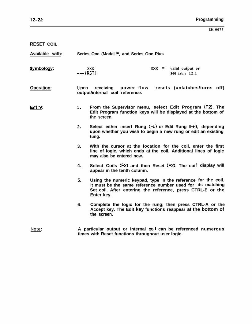
12-22 Programming
RESET COIL
Available with: Series One (Model E) and Series One Pius
Symbology:
Operation:
Entrv:
Note:
UK-0075
xxx xxx = valid output or---(RST> see table 12.1
Upon receiving power flow resets (unlatches/turns off)output/internal coil reference.
1 .
2 .
3 .
4 .
5 .
6 .
From the Supervisor menu, select Edit Program (F2). TheEdit Program function keys will be displayed at the bottom ofthe screen.
Select either insert Rung (F5) or Edit Rung (F6), dependingupon whether you wish to begin a new rung or edit an existingtung.
With the cursor at the location for the coil, enter the firstline of logic, which ends at the coil. Additional lines of logicmay also be entered now.
Select Coils (F2) and then Reset (F2). The coi Iappear in the tenth column.
Using the numeric keypad, type in the reference for the coil.It must be the same reference number used for its matching
display will
Set coil. After entering the reference, press CTRL-E or theEnter key.
Complete the logic for the rung; then press CTRL-A or theAccept key. The Edit key functions reappear at the bottom ofthe screen.
A particular output or internal coil can be referenced numeroustimes with Reset functions throughout user logic.
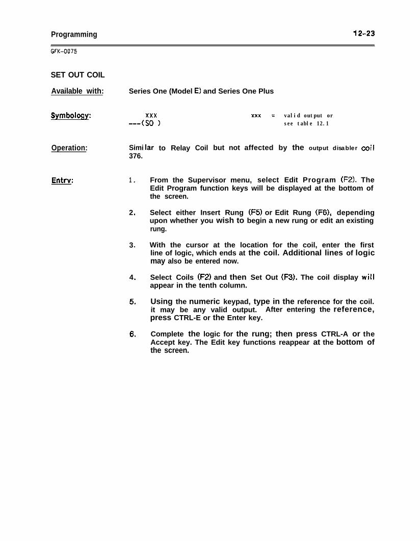
Programming 12-23
GFK-OC75
SET OUT COIL
Available with:
Symbolog:
Operation:
Entrv:
Series One (Model E) and Series One Plus
xxx---(SO 1
xxx = valid output orsee table 12.1
Simi376.
lar to Relay Coil but not affected by the output disabler coil
1 .
2 .
3 .
4 .
5 .
6 .
From the Supervisor menu, select Edit Program (FZ). TheEdit Program function keys will be displayed at the bottom ofthe screen.
Select either Insert Rung (FS) or Edit Rung (F6), dependingupon whether you wish to begin a new rung or edit an existingrung.
With the cursor at the location for the coil, enter the firstline of logic, which ends at the coil. Additional lines of logicmay also be entered now.
Select Coils (F2) and then Set Out (F3). The coil display willappear in the tenth column.
Using the numeric keypad, type in the reference for the coil.it may be any valid output. After entering the reference,press CTRL-E or the Enter key.
Complete the logic for the rung; then press CTRL-A or theAccept key. The Edit key functions reappear at the bottom ofthe screen.
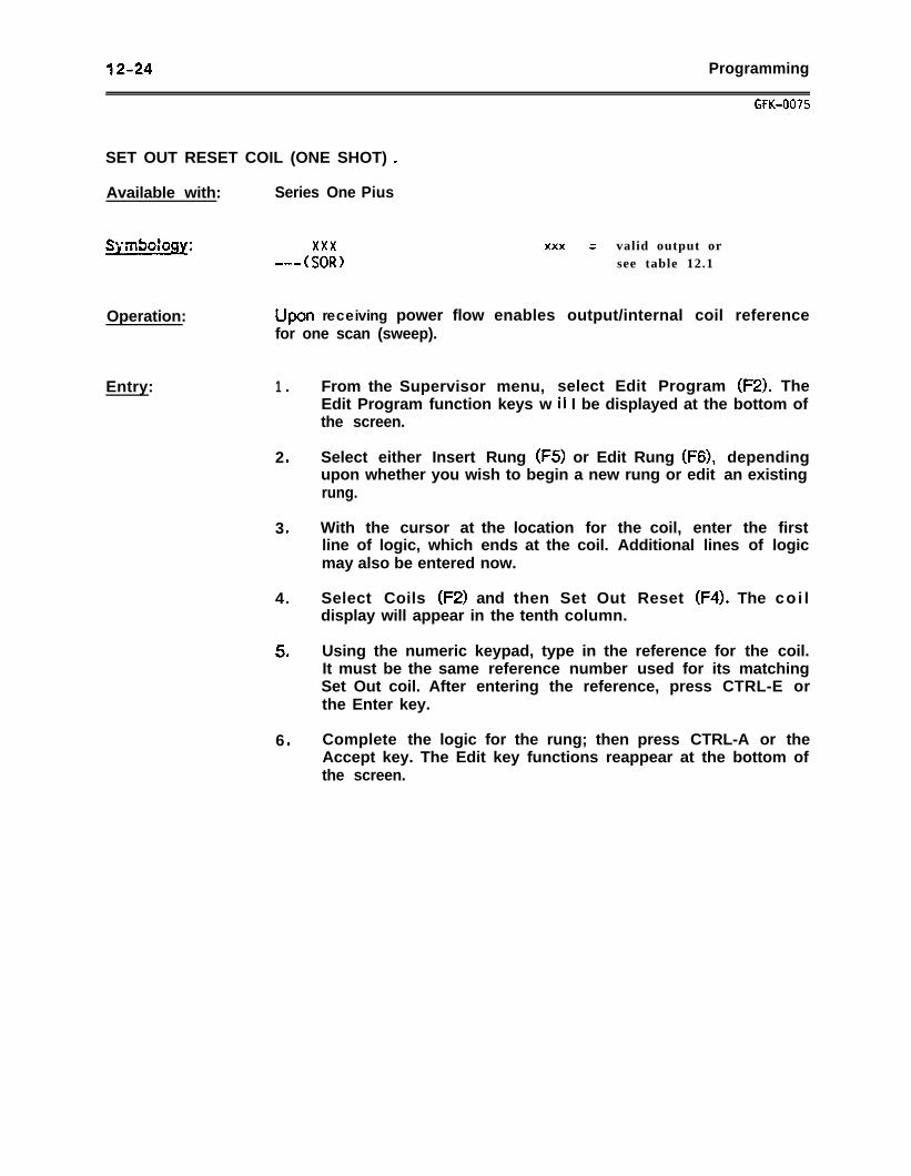
12-24 Programming
GFK-007s
SET OUT RESET COIL (ONE SHOT) a
Available with: Series One Pius
Symbology: xxx xxx = valid output or--ASOR) see table 12.1
Operation: upon receiving power flow enables output/internal coil referencefor one scan (sweep).
Entry: 1 .
2 .
3 .
4 .
5 .
6 .
From the Supervisor menu, select Edit Program (FZ). TheEdit Program function keys w if I be displayed at the bottom ofthe screen.
Select either Insert Rung (F5) or Edit Rung (F6), dependingupon whether you wish to begin a new rung or edit an existingrung.
With the cursor at the location for the coil, enter the firstline of logic, which ends at the coil. Additional lines of logicmay also be entered now.
Select Coils (F2) and then Set Out Reset (F4). The co i ldisplay will appear in the tenth column.
Using the numeric keypad, type in the reference for the coil.It must be the same reference number used for its matchingSet Out coil. After entering the reference, press CTRL-E orthe Enter key.
Complete the logic for the rung; then press CTRL-A or theAccept key. The Edit key functions reappear at the bottom ofthe screen.
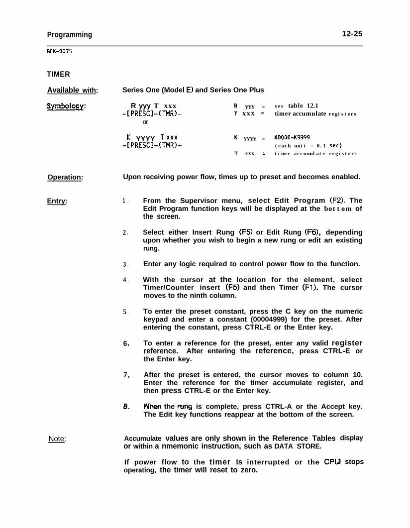
Programming 12-25
GFK-OG75
TIMER
Available with: Series One (Model E) and Series One Plus
Symbology:
Operation:
Entry:
Note:
R yyy T xxx-[PRESCl-(TMRL
Of
R YYY = see table 12.11 xxx = timer accumulate registers
K YYYY T xxx-IPRESCl-(TMR)-
K YYYY = KOOObK9999(each unit = 0.1 set)
T xxx = timer accumulate registers
Upon receiving power flow, times up to preset and becomes enabled.
1 .
2 .
3 .
4 .
5 .
6 .
7 .
8 ”
From the Supervisor menu, select Edit Program (F2). TheEdit Program function keys will be displayed at the bottom ofthe screen.
Select either Insert Rung (F5) or Edit Rung (F6), dependingupon whether you wish to begin a new rung or edit an existingrung.
Enter any logic required to control power flow to the function.
With the cursor at the location for the element, selectTimer/Counter insert (F5) and then Timer (Fl). The cursormoves to the ninth column.
To enter the preset constant, press the C key on the numerickeypad and enter a constant (00004999) for the preset. Afterentering the constant, press CTRL-E or the Enter key.
To enter a reference for the preset, enter any valid registerreference. After entering the reference, press CTRL-E orthe Enter key.
After the preset is entered, the cursor moves to column 10.Enter the reference for the timer accumulate register, andthen press CTRL-E or the Enter key.
VY’hen the rung is complete, press CTRL-A or the Accept key.The Edit key functions reappear at the bottom of the screen.
Accumulate values are only shown in the Reference Tablesor within a nmemonic instruction, such as DATA STORE.
If power flow to the timer is interrupted or the CPloperating, the timer will reset to zero.
display
J stops
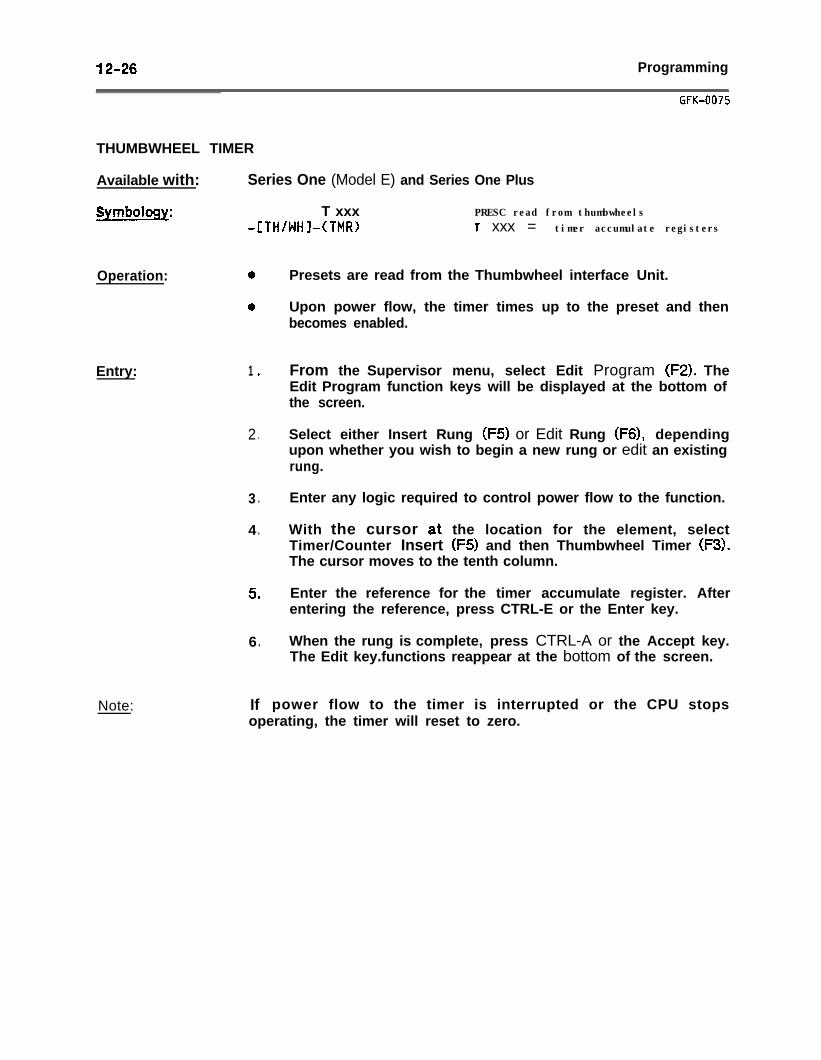
12-26 Programming
THUMBWHEEL TIMER
Available with: Series One (Model E) and Series One Plus
Symbology: T xxx-[TH/hJHl-(TMR)
PRESC read from thumbwheelsT xxx = timer accumulate registers
Operation:
Entry:
Note:
1 .
2 .
3 .
4 .
5 .
6 .
If power flow to the timer is interrupted or the CPU stops
Presets are read from the Thumbwheel interface Unit.
Upon power flow, the timer times up to the preset and thenbecomes enabled.
From the Supervisor menu, select Edit Program (F2). TheEdit Program function keys will be displayed at the bottom ofthe screen.
Select either Insert Rung (F5) or Edit Rung (F6), dependingupon whether you wish to begin a new rung or edit an existingrung.
Enter any logic required to control power flow to the function.
With the cursor at the location for the element, selectTimer/Counter Insert (FS) and then Thumbwheel Timer (F3!.The cursor moves to the tenth column.
Enter the reference for the timer accumulate register. Afterentering the reference, press CTRL-E or the Enter key.
When the rung is complete, press CTRL-A or the Accept key.The Edit key.functions reappear at the bottom of the screen.
operating, the timer will reset to zero.
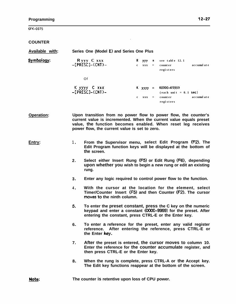
Programming 12-27
.COUNTER
Available with: Series One (Model E) and Series One Plus
Symbology:
Operation:
Entry:
R yyy C xxx-[PRESCl-KNT>-
R YYY = see table 12.1c xxx = counter accumulate
registers
Of
K YYYY c xxx-[PRESCl-KNTL
K YYYY = KOOOO-Kg999(each unit = 0.1 set)
c xxx = counter accumulateregisters
Upon transition from no power flow to power flow, the counter’scurrent value is incremented. When the current value equals presetvalue, the function becomes enabled. When reset leg receivespower flow, the current value is set to zero.
1 .
2 .
3 .
4 .
5 .
6 .
7 .
8 .
From the Supervisor menu, select Edit Program (F2). TheEdit Program function keys will be displayed at the bottom ofthe screen.
Select either Insert Rung (F5) or Edit Rung (F6), dependingupon whether you wish to begin a new rung or edit an existingrung.
Enter any logic required to control power flow to the function.
With the cursor at the location for the element, selectTimer/Counter Insert (F5) and then Counter (F2). The cursormoves”to the ninth column.
To enter the preset constant, press the C key on the numerickeypad and enter a constant (00004999) for the preset. Afterentering the constant, press CTRL-E or the Enter key.
To enter a reference for the preset, enter any valid registerreference. After entering the reference, press CTRL-E orthe Enter key.
After the preset is entered, the cursor moves to column 10.Enter the reference for the counter accumulate register, andthen press CTRL-E or the Enter key.
When the rung is complete, press CTRL-A or the Accept key.The Edit key functions reappear at the bottom of the screen.
The counter is retentive upon loss of CPU power.
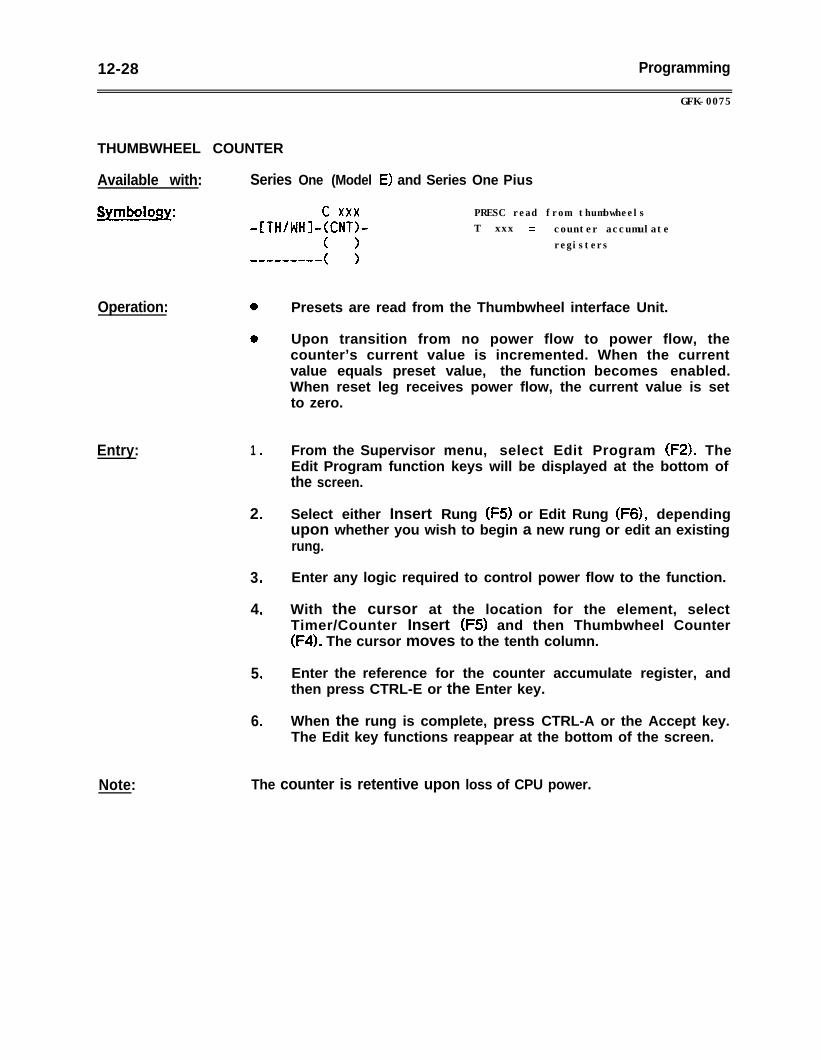
12-28 Programming
THUMBWHEEL COUNTER
Available with: Series One (Model E) and Series One Pius
Symbology:
Operation:
Entry:
Note:
c xxx-[TH/WHI-KNT>-
( >
GFK-0075
PRESC read from thumbwheelsT xxx = counter accumulate
registers
1 .
2 .
3 .
4 .
5 .
6 .
Presets are read from the Thumbwheel interface Unit.
Upon transition from no power flow to power flow, thecounter’s current value is incremented. When the currentvalue equals preset value, the function becomes enabled.When reset leg receives power flow, the current value is setto zero.
From the Supervisor menu, select Edit Program (FZ). TheEdit Program function keys will be displayed at the bottom ofthe screen.
Select either Insert Rung (F5) or Edit Rung (F6), dependingupon whether you wish to begin a new rung or edit an existingrung.
Enter any logic required to control power flow to the function.
With the cursor at the location for the element, selectTimer/Counter Insert (F5) and then Thumbwheel Counter(F4). The cursor moves to the tenth column.
Enter the reference for the counter accumulate register, andthen press CTRL-E or the Enter key.
When the rung is complete, press CTRL-A or the Accept key.The Edit key functions reappear at the bottom of the screen.
The counter is retentive upon loss of CPU power.
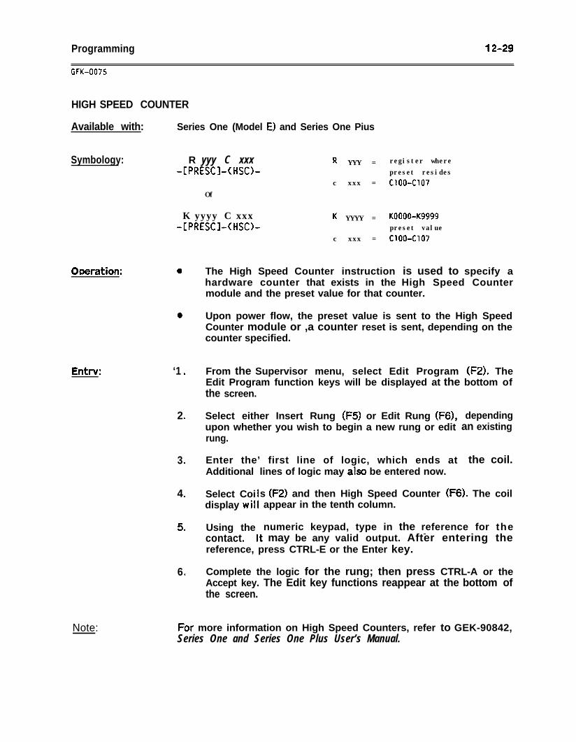
Programming 12-29
GFK-0075
HIGH SPEED COUNTER
Available with: Series One (Model E) and Series One Pius
Symbology: R yyy C xxx-[PRESCl-(HSCb
Of
R YYY = register wherepreset resides
c xxx = c1004107
K yyyy C xxx-IPRESCl-(HSO-
K YYYY = KOOObK9999preset value
c xxx = ClOO-Cl07
Ooefation:
E&v:
Note:
0 The High Speed Counter instruction is used to specify ahardware counter that exists in the High Speed Countermodule and the preset value for that counter.
0 Upon power flow, the preset value is sent to the High SpeedCounter module or ,a counter reset is sent, depending on thecounter specified.
‘1 .
2 .
3 .
4 .
5 .
6 .
From the Supervisor menu, select Edit Program (F2). TheEdit Program function keys will be displayed at the bottom ofthe screen.
Select either Insert Rung (F5) or Edit Rung (F6),upon whether you wish to begin a new rung or editrung.
dependingan existing
Enter the’ first line of logic, which ends at the coil.Additional lines of logic may also be entered now.
Select Coidisplay wit
s (FZ) and then High Speed Counter (F6). The coilappear in the tenth column.
Using the numeric keypad, type in the reference for the- _contact. It may be any valid output. After entering thereference, press CTRL-E or the Enter key.
Complete the logic for the rung; then press CTRL-A or theAccept key. The Edit key functions reappear at the bottom ofthe screen.
CIror more information on High Speed Counters, refer to GEK-90842,Series One and Series One Plus User’s Manual.
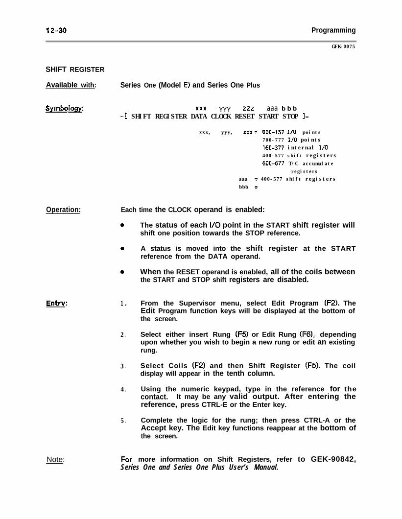
12-30 Programming
GFK-0075
SHIFT REGISTER
Available with: Series One (Model E) and Series One Plus
Symboiogy:
Operation: Each time the CLOCK operand is enabled:
Note:
xxx YYY zzz aaa b b b-1 SHIFT REGISTER DATA CLOCK RESET START STOP I-
xxx, yyy, zzz = 000-157 I/O points700-777 I/O points160-377 internal I/O400-577 shift registers600-677 T/C accumulate
registersaaa = 400-577 shift registersbbb =
1 0
2 .
3 .
4 .
5 .
For
The status of each I/O point in the START shift register willshift one position towards the STOP reference.
A status is moved into the shift register at the STARTreference from the DATA operand.
When the RESET operand is enabled, all of the coils betweenthe START and STOP shift registers are disabled.
From the Supervisor menu, select Edit Program (F2). TheEdit Program function keys will be displayed at the bottom ofthe screen.
Select either insert Rung (F5) or Edit Rung (F6), dependingupon whether you wish to begin a new rung or edit an existingrung.
Select Coils (F2) and then Shift Register (F5). The coildisplay will appear in the tenth column.
Using the numeric keypad, type in the reference for thecontact. It may be any valid output. After entering thereference, press CTRL-E or the Enter key.
Complete the logic for the rung; then press CTRL-A or theAccept key. The Edit key functions reappear at the bottom ofthe screen.
more information on Shift Registers, refer to GEK-90842,Series One and Series One Plus User’s Manual.
Data Operation Instructions 13-l
UK-0075
CHAPTER 13DATA OPERATION INSTRUCTIONS
FOR THE SERIES ONE PLUS PLC
in addition to the basic ladder diagram functions, the Series One Pius PLC has a group ofinstructions that include data moves, math functions, logic operations, conversion, andexternal fault diagnosis. These instructions provide the Series One Plus PLC with thecapability of performing various data operations. The instructions operate on multiplebits, rather than one bit at a time, and are available only with the Series One Plus PLC.
This chapter contains the following sections:
Section I. Data Operations: Section 1 describes how to use data operation instructionsto program the Series One Plus PLC.
Section 2. Data Move Operations: Sect ion 2 covers the Data Move functions available inthe Series One Plus PLC.
Section 3. Arithmetic Operations: Section 3 covers the Math functions available in theSeries One Plus PLC.
Section 4. Logic Operations: Section 4 covers the Logic operations available in theSeries One Plus PLC.
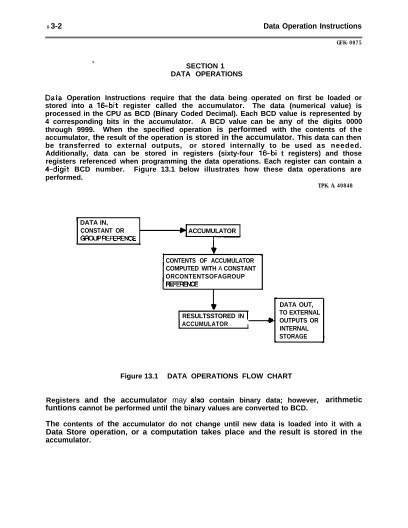
‘i 3-2 Data Operation Instructions
GFK-0075
r
SECTION 1DATA OPERATIONS
Dai;a Operation Instructions require that the data being operated on first be loaded orstored into a 16.bit register called the accumulator. The data (numerical value) isprocessed in the CPU as BCD (Binary Coded Decimal). Each BCD value is represented by4 corresponding bits in the accumulator. A BCD value can be any of the digits 0000through 9999. When the specified operation is performed with the contents of theaccumulator, the result of the operation is stored in the accumulator. This data can thenbe transferred to external outputs, or stored internally to be used as needed.Additionally, data can be stored in registers (sixty-four 160bi t registers) and thoseregisters referenced when programming the data operations. Each register can contain a4-digit BCD number. Figure 13.1 below illustrates how these data operations areperformed. .
TPK.A.40848
’ DATA IN,I
\ ,CONSTANT OR / b ACCUMULATORGf3oUPm
& \
CONTENTS OF ACCUMULATORCOMPUTED WITH A CONSTANTORCONTENTSOFAGROUP
1 RESULTSSTORED IN 1ACCUMULATOR I
DATA OUT,TO EXTERNALOUTPUTS ORINTERNALSTORAGE
Figure 13.1 DATA OPERATIONS FLOW CHART
Registers and the accumulator may also contain binary data; however,funtions cannot be performed until the binary values are converted to BCD.
arithmetic
The contents of the accumulator do not change until new data is loaded into it with aData Store operation, or a computation takes place and the result is stored in theaccumulator.
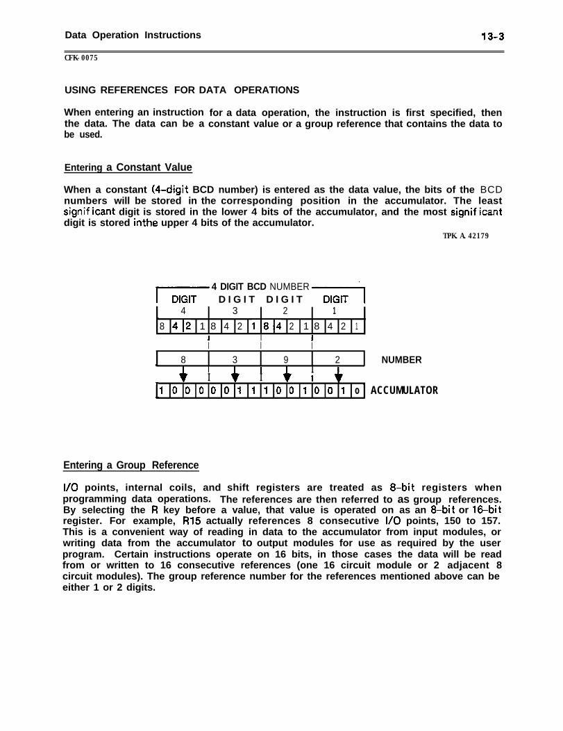
Data Operation Instructions 13-3
CFK-0075
USING REFERENCES FOR DATA OPERATIONS
When entering an instructionthe data. The data can be abe used.
for a data operation, the instruction is first specified, thenconstant value or a group reference that contains the data to
Entering a Constant Value
When a constant (40digit BCD number) is entered as the data value, the bits of the BCDnumbers will be stored in the corresponding position in the accumulator. The leastsignif icant digit is stored in the lower 4 bits of the accumulator, and the most signif icantdigit is stored inthe upper 4 bits of the accumulator.
TPK.A.42179
4 DIGIT BCD NUMBERE D I G I T D I G I T ‘Ft
4 3 2 1r8 412 1 8 4 2 1814 2 1 8 4 2 1
I I II I I.
8 3 9 2 NUMBERWI I II I I? I
1 0 o o o o 1 f 1 0 o 1 0 o 1 o ACCUMULATORP-
Entering a Group Reference
l/O points, internal coils, and shift registers are treated as 8-bit registers whenprogramming data operations. The references are then referred to as group references.By selecting the R key before a value, that value is operated on as an 8-bit or 160bitregister. For example, R15 actually references 8 consecutive I/O points, 150 to 157.This is a convenient way of reading in data to the accumulator from input modules, orwriting data from the accumulator to output modules for use as required by the userprogram. Certain instructions operate on 16 bits, in those cases the data will be readfrom or written to 16 consecutive references (one 16 circuit module or 2 adjacent 8circuit modules). The group reference number for the references mentioned above can beeither 1 or 2 digits.
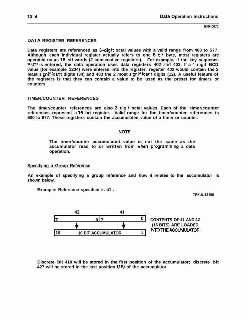
13-4 Data Operation Instructions
GFK-0075
DATA REGISTER REFERENCES
Data registers ate referenced as 3-digit octal values with a valid range from 400 to 577.Although each individual register actually refers to one 8-bit byte, most registers areoperated on as 16-bit words (2 consecutive registers). For example, if the key sequenceR402 is entered, the data operation uses data registers 402 and 403. If a 4-digit BCDvalue (for example 1234) were entered into the register, register 402 would contain the 2least signif icant digits (34) and 403 the 2 most signif icant digits (12). A useful feature ofthe registers is that they can contain a value to be used as the preset for timers orcounters.
TIMER/COUNTER REFERENCES
The timer/counter references are also 3-digit octal values. Each of the timer/counterreferences represent a 160bit register. Valid range for the timer/counter references is600 to 677. These registers contain the accumulated value of a timer or counter.
NOTE
The timer/counter accumulated value is not the same as theaccumulator read to or written from whenxrogramming a dataoperation.
Specifying a Group Reference
An example of specifying a group reference and how it relates to the accumulator isshown below.
Example: Reference specified is 41 lTPK.A.42156
42 41b /7 0 7 ol
CONTENTS OF 41 AND 42
+ +(16 BITS) ARE LOADED
16 16 BIT ACCUMULATOR 1 + INTOTHEACCUMULATOR\ _
Discrete bit 410 will be stored in the first position of the accumulator; discrete bit427 will be stored in the last position (16) of the accumulator.
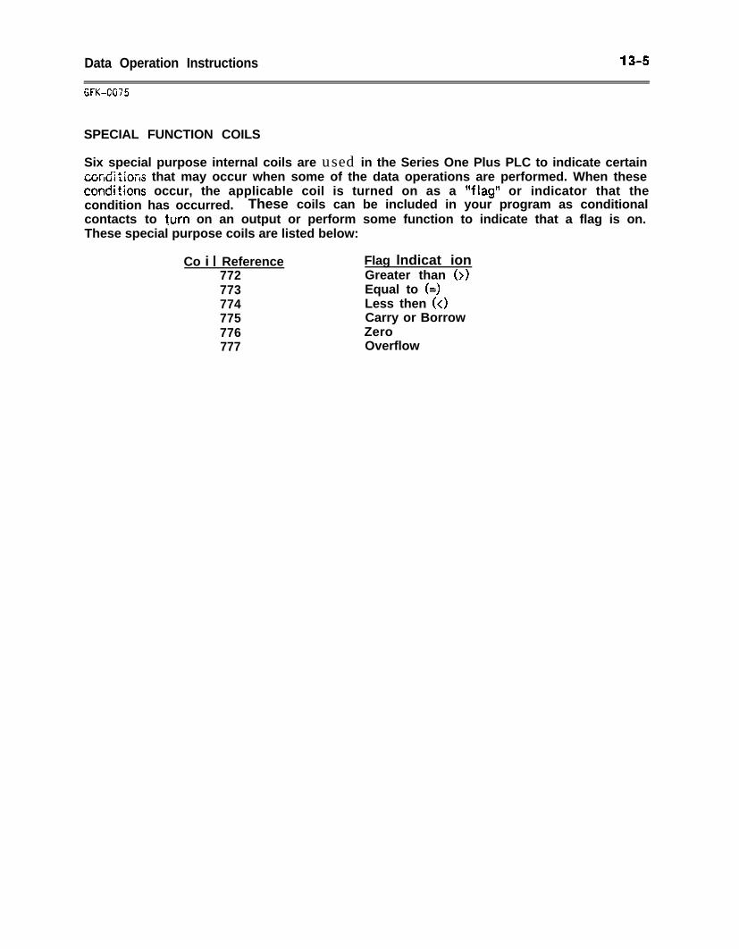
Data Operation Instructions 13-s
GFK-GG75
SPECIAL FUNCTION COILS
Six special purpose internal coils are used in the Series One Plus PLC to indicate certainc~r-ditims that may occur when some of the data operations are performed. When thesecondi?icns occur, the applicable coil is turned on as a “flag*’ or indicator that thecondition has occurred. These coils can be included in your program as conditionalcontacts to turn on an output or perform some function to indicate that a flag is on.These special purpose coils are listed below:
Co i I Reference Flag lndicat ion772 Greater than (>)773 Equal to (=)774 Less then (<I775 Carry or Borrow776 Zero777 Overflow
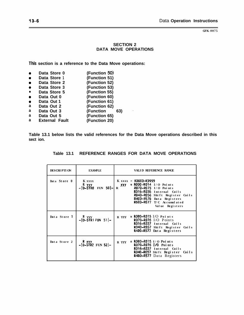
13-6 Data Operation Instructions
GFK-0075
SECTION 2DATA MOVE OPERATIONS
This section is a reference to the Data Move operations:
0 Data Store 00 Data Store 10 Data Store 20 Data Store 3l Data Store 50 Data Out 00 Data Out 1a Data Out 2a Data Out 3a Data Out 5a External Fault
(Function 50)(Function 51)(Function 52)(Function 53)(Function 55)(Function 60)(Function 61)(Function 62)(Function 63) .(Function 65)(Function 20)
Table 13.1 below lists the valid references for the Data Move operations described in thissect ion.
Table 13.1 REFERENCE RANGES FOR DATA MOVE OPERATIONS
DESCRIPTION EXAMPLE VALID REFERENCE RANGE
Data Store 0 K xxxx K xxxx = KOOOO-Kg999
-I;-& FUN 501- R "'= ROOO-R014 I/O Points'R070-R075 I/O PointsR016-R036 Internal CoilsR040-R056 Shift Register CoilsR400-R576 Data RegistersRbOO-R677 T/C Accumulated
Value Registers
Data Store 1 R YYY R YYY = ROOO-ROl5 I/O Points-JO-STR~ FUN 511- R070-R076 I/O Points
ROl6-R037 Internal CoilsR040-R057 Shift Register CoilsR400-R577 Data Registers
Data Store 2$&2 FUN 5210
R YYY = ROOO-R015 I/O PointsRO70-R076 I/O PointsR016-R037 Internal CoilsR040-R057 Shift Register CoilsR400-R577 Data Registers
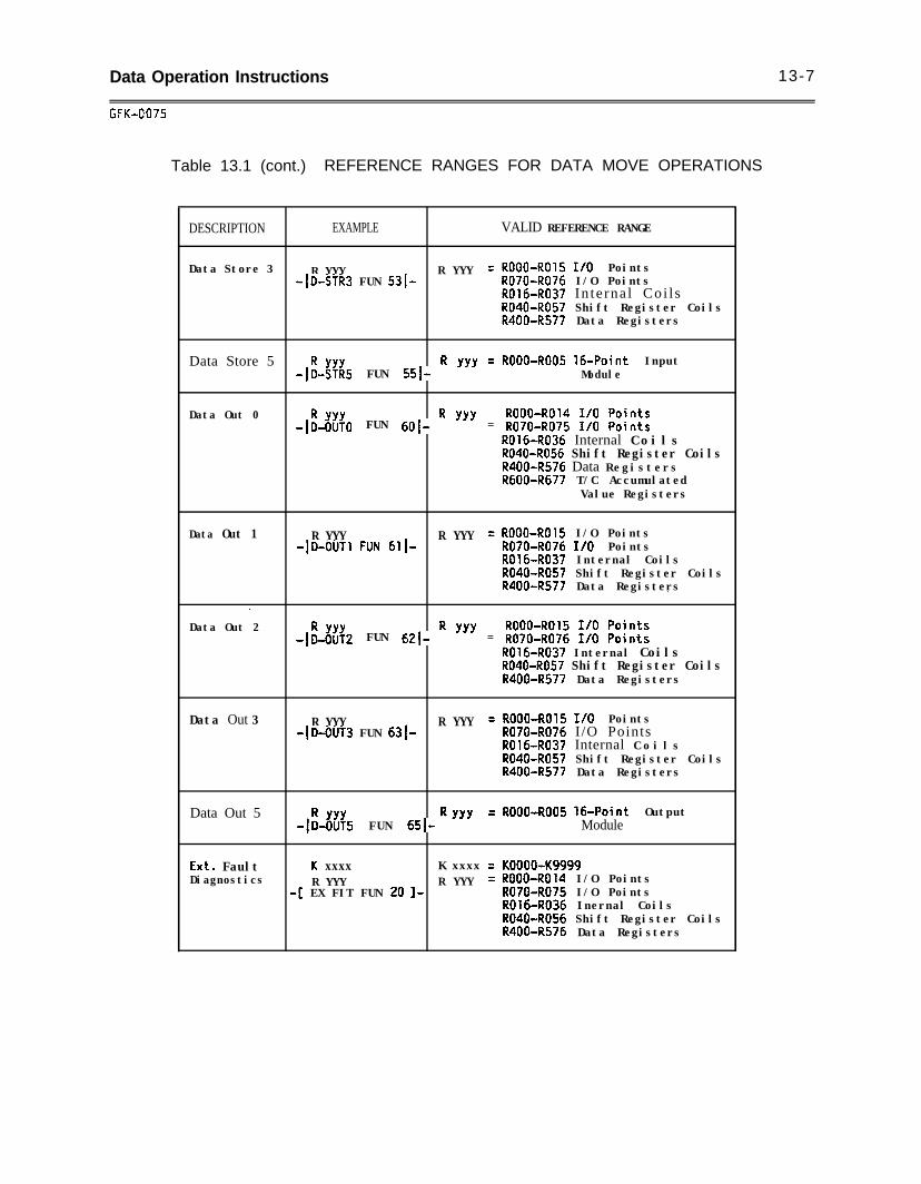
Data Operation Instructions 13-7
GFK-GO75
Table 13.1 (cont.) REFERENCE RANGES FOR DATA MOVE OPERATIONS
DESCRIPTION EXAMPLE VALID REFERENCE RANGE
Data Store 3 R YYY R YYY = ROOO-R015 I/O Points-(D-STR3 FUN 5310 R070-R076 I/O Points
R016-R037 In te rna l Coi l sR040-R057 Shift Register CoilsR400-R577 Data Registers
Data Store 5-$-;!~5 FUN Ssf- R "' -
- ROOO-R005 160Point InputModule
Data Out 0$&;O FUN 6()1- R "' = ;;;;:;i;; :;; ;$$;
R016-R036 Internal C o i l sR040-R056 Shift Register CoilsR400-R576 Data RegistersRdOO-R677 T/C Accumulated
Value Registers
Data Out 1 R YYY R YYY = ROOO-8015 I/O Points-ID-ouT~ FUN 611. R070-R076 I/O Points
R016-R037 Internal CoilsR040-R057 Shift Register CoilsR400-R577 Data Registers.
.Data Out 2
$& FUN 62(- R "' = ;;;i:;;;; ;;; ;;i;::R016-R037 Internal CoilsR040-R057 Shift Register CoilsR400-R577 Data Registers
Data Out 3 R YYY = ROOO-R015 I/O Points-(D-OUT3 FUN 6310.
R YYYR070-R076 I/O PointsR016-R037 Internal C o i l sR040-R057 Shift Register CoilsR400-R577 Data Registers
Data Out 5$-6;;5 FUN 6510 R “’
= ROOO-R005 160Point OutputModule
Ext. Fault u xxxx K xxxx = KOOOO-Kg999Diagnostics R YYY R YYY = ROOO-R014 I/O Points
-[ EX FIT FUN 20 l- R070-R075 I/O PointsR016-R036 Inernal CoilsR040-R056 Shift Register CoilsR400-R576 Data Registers
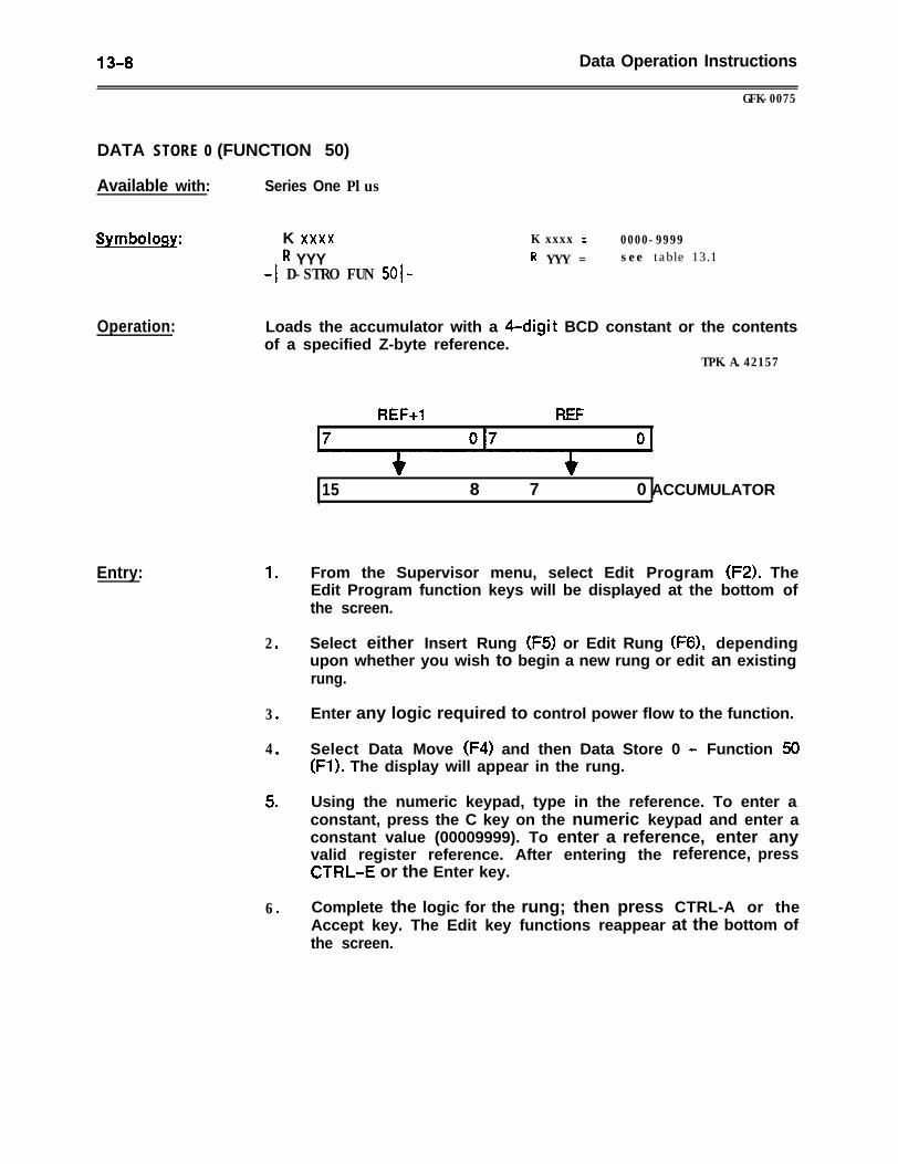
13-8 Data Operation Instructions
GFK-0075
DATA STORE 0 (FUNCTION 50)
Available with: Series One Plus
Symbology: K xxxxR YYY
-1 D-STRO FUN SOI-
K xxxx = 0000-9999R YYY = see table 13.1
Operation:
Entry:
Loads the accumulator with a 4-digit BCD constant or the contentsof a specified Z-byte reference.
TPK.A.42157
1 .
2 .
3 .
4 .
5 .
6 .
REF+l REF
15 8 7 0 ACCUMULATOR, b
From the Supervisor menu, select Edit Program (F2). TheEdit Program function keys will be displayed at the bottom ofthe screen.
Select either Insert Rung (F5) or Edit Rung (F6), dependingupon whether you wish to begin a new rung or edit an existingrung.
Enter any logic required to control power flow to the function.
Select Data Move (F4) and then Data Store 0 - Function 50(Fl). The display will appear in the rung.
Using the numeric keypad, type in the reference. To enter aconstant, press the C key on the numeric keypad and enter aconstant value (00009999). To enter a reference, enter anyvalid register reference. After entering theCTRL-E or the Enter key.
reference, press
Complete the logic for the rung; then pressAccept key. The Edit key functions reappearthe screen.
CTRL-A or theat the bottom of
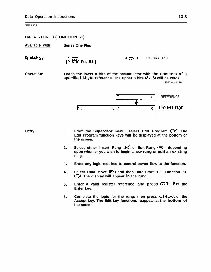
Data Operation Instructions 13-S
GFK-0075
DATA STORE I (FUNCTION 51)
Available with: Series One Plus
Symbology: R YYY-ID-STR~ FUN 51 I-
R YYY = see table 13.1
Operation: Loads the lower 8 bits of the accumulator with the contents of aspecified l-byte reference. The upper 8 bits (8-15) will be zeros.
TPK.A.42158
Entry:
c115 817
REFERENCE
ACCUMUIATOR
1 . From the Supervisor menu, select Edit Program (F2). TheEdit Program function keys will be displayed at the bottom ofthe screen.
2 . Select either Insert Rung (F5) or Edit Rung (F6), dependingupon whether you wish to begin a new rung or edit an existingrung.
. I
3 . Enter any logic required to control power flow to the function.
4 . Select Data Move (F4) and then Data Store 1 - Function 51(F3). The display will appear in the rung.
5 . Enter a valid register reference, and press CTRL-E or theEnter key.
6 . Complete the logic for the rung; then press CTRL-A or theAccept key. The Edit key functions reappear at the bottom ofthe screen.
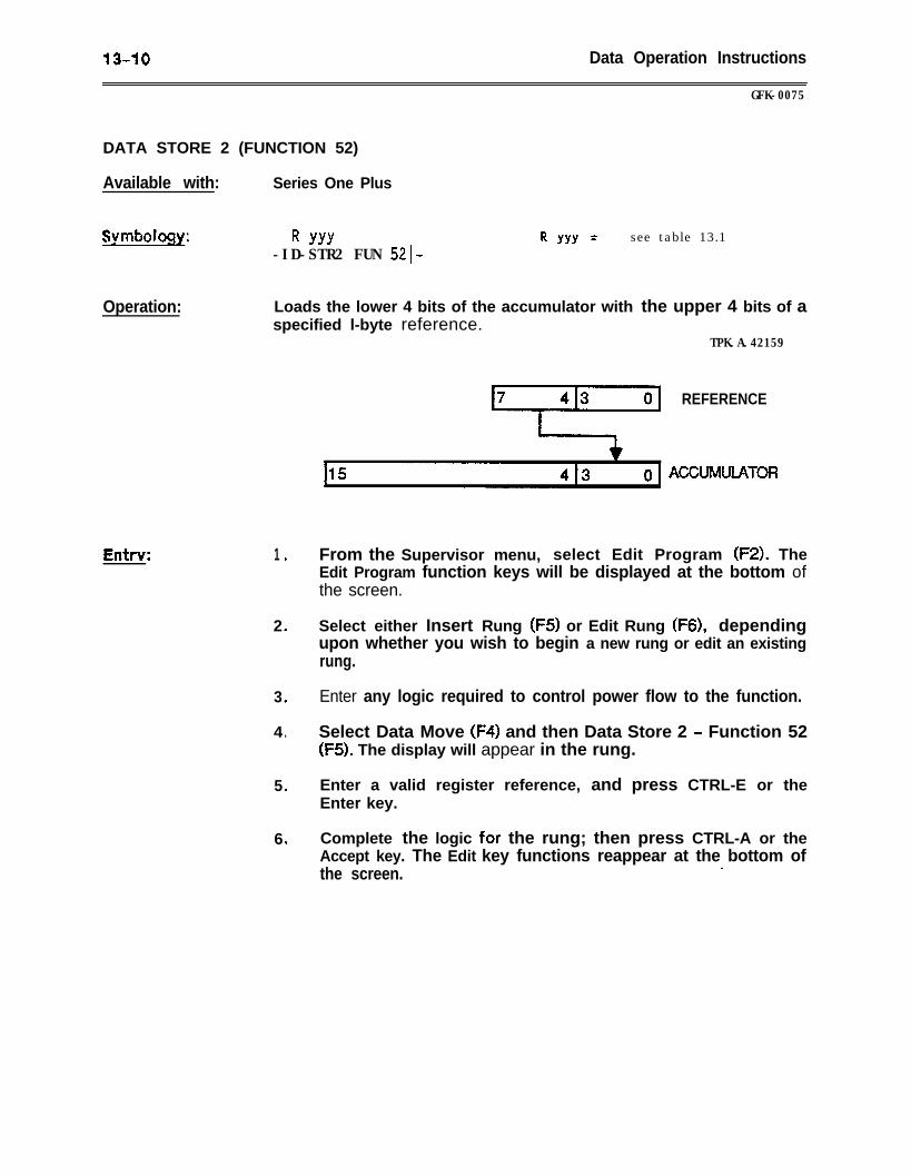
13-10 Data Operation Instructions
GFK-0075
DATA STORE 2 (FUNCTION 52)
Available with: Series One Plus
Symbology: R YYY-ID-STR2 FUN 521-
R YYY = see table 13.1
Operation: Loads the lower 4 bits of the accumulator with the upper 4 bits of aspecified l-byte reference.
TPK.A.42159
REFERENCE
Entrv:
ACCUMUlATOR
1 . From the Supervisor menu, select Edit Program (F2). TheEdit Program function keys will be displayed at the bottom ofthe screen.
2 . Select either Insert Rung (F5) or Edit Rung (F6), dependingupon whether you wish to begin a new rung or edit an existingrung.
3 . Enter any logic required to control power flow to the function.
4 . Select Data Move (F4) and then Data Store 2 - Function 52(F5). The display will appear in the rung.
5 . Enter a valid register reference, and press CTRL-E or theEnter key.
6 . Complete the logic for the rung; then press CTRL-A or theAccept key. The Edit key functions reappear at the bottom ofthe screen.
.
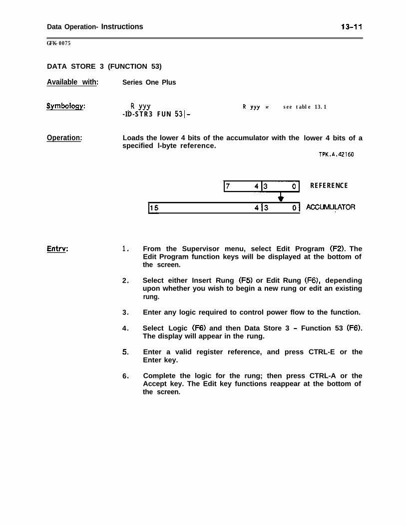
Data Operation- Instructions 13-11
GFK-0075
DATA STORE 3 (FUNCTION 53)
Available with: Series One Plus
Symbology: _ R YYY- ID-STR3 FUN 5310
R YYY = see table 13.1
Operation: Loads the lower 4 bits of the accumulator with thespecified l-byte reference.
Entrv:
413 01
lower 4 bits of a
TPK.A.42160
REFERENCE
ACCUMUVlrTORM
1 .
2 .
3 .
4 .
5 .
6 .
From the Supervisor menu, select Edit Program (FZ). TheEdit Program function keys will be displayed at the bottom ofthe screen.
Select either Insert Rung (F5) or Edit Rung (F6), dependingupon whether you wish to begin a new rung or edit an existingrung.
Enter any logic required to control power flow to the function.
Select Logic (F6) and then Data Store 3 - Function 53 (F6).The display will appear in the rung.
Enter a valid register reference, and press CTRL-E or theEnter key.
Complete the logic for the rung; then press CTRL-A or theAccept key. The Edit key functions reappear at the bottom ofthe screen.
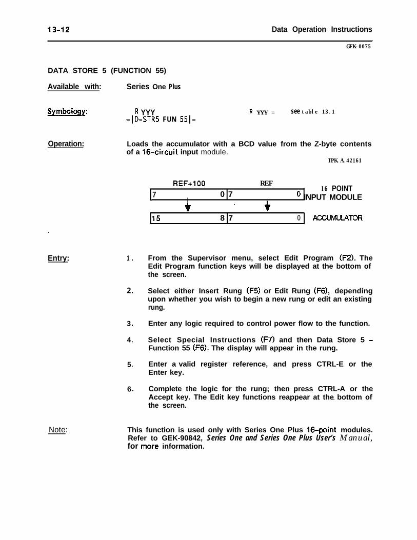
13-12 Data Operation Instructions
GFK-0075
DATA STORE 5 (FUNCTION 55)
Available with: Series One Plus
Symbdou: R YYY-1 D-STRS FUN 5510
R YYY = see table 13.1
Operation: Loads the accumulator with a BCD value from the Z-byte contentsof a 164rcuit input module.
TPK.A.42161
REF+lOO REF0 7
16 POINT7t ’ INPUT MODULEI I
Ir. f
15 8 7 0 ACCUMUIATOR
.
Entry: 1 .
Note:
2 .
3 .
4 .
5 .
6 .
From the Supervisor menu, select Edit Program (F2). TheEdit Program function keys will be displayed at the bottom ofthe screen.
Select either Insert Rung (F5) or Edit Rung (F6), dependingupon whether you wish to begin a new rung or edit an existingrung.
Enter any logic required to control power flow to the function.
Select Special Instructions (F7) and then Data Store 5 -Function 55 (F6). The display will appear in the rung.
Enter a valid register reference, and press CTRL-E or theEnter key.
Complete the logic for the rung; then press CTRL-A or theAccept key. The Edit key functions reappear at the bottom of_the screen.
This function is used only with Series One Plus 16.point modules.Refer to GEK-90842, Series One and Series One Plus User’s Manual,for mofe information.
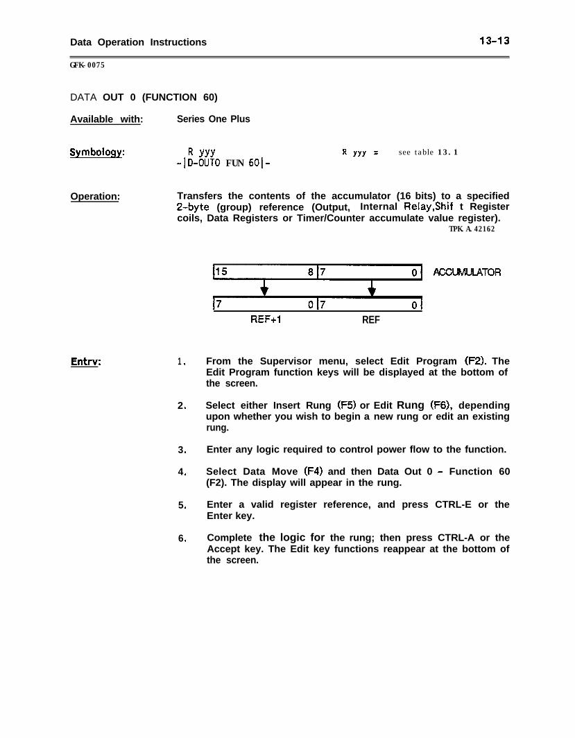
Data Operation Instructions 13-13
GFK-0075
DATA OUT 0 (FUNCTION 60)
Available with: Series One Plus
Symbology: R YYY-ID-OUT0 FUN 6010
R YYY = see table 13.1
Operation: Transfers the contents of the accumulator (16 bits) to a specified2-byte (group) reference (Output, Internal Relay,Shif t Registercoils, Data Registers or Timer/Counter accumulate value register).
TPK.A.42162
Entry: 1 .
2 .
3 .
4 .
5 .
6 .
ACCUhNJLATOR
REF+l REF
From the Supervisor menu, select Edit Program (F2). TheEdit Program function keys will be displayed at the bottom ofthe screen.
Select either Insert Rung (F5) or Edit Rung (F6), dependingupon whether you wish to begin a new rung or edit an existingrung.
Enter any logic required to control power flow to the function.
Select Data Move (F4) and then Data Out 0 - Function 60(F2). The display will appear in the rung.
Enter a valid register reference, and press CTRL-E or theEnter key.
Complete the logic for the rung; then press CTRL-A or theAccept key. The Edit key functions reappear at the bottom ofthe screen.
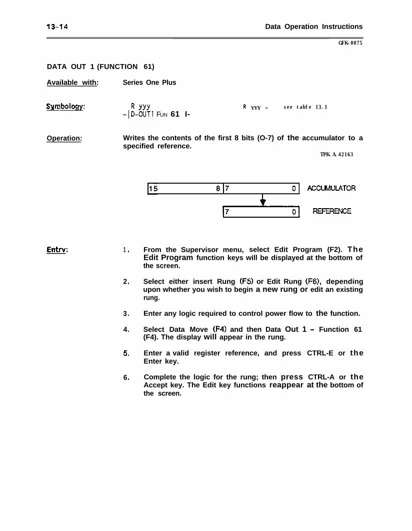
13-14 Data Operation Instructions
GFK-0075
DATA OUT 1 (FUNCTION 61)
Available with: Series One Plus
%m_boIogy:I - I? YYY+-0~Ti FUN 61 I-
f? YYY = see table 13.1
Operation: Writes the contents of the first 8 bits (O-7) of the accumulator to aspecified reference.
TPK.A.42163
8 179
0 ACCUMUIATOR
Entt-v: 1 .
2 .
3 .
4 .
5 .
6 .
From the Supervisor menu, select Edit Program (F2). TheEdit Program function keys will be displayed at the bottom ofthe screen.
Select either insert Rung (F5) or Edit Rung (F6), dependingupon whether you wish to begin a new rung or edit an existingrung.
Enter any logic required to control power flow to the function.
Select Data Move (F4) and then Data Out 1 - Function 61(F4). The display will appear in the rung.
Enter a valid register reference, and pressEnter key.
Complete the logic for the rung; then pressAccept key. The Edit key functions reappearthe screen.
CTRL-E or the
CTRL-A or theat the bottom of
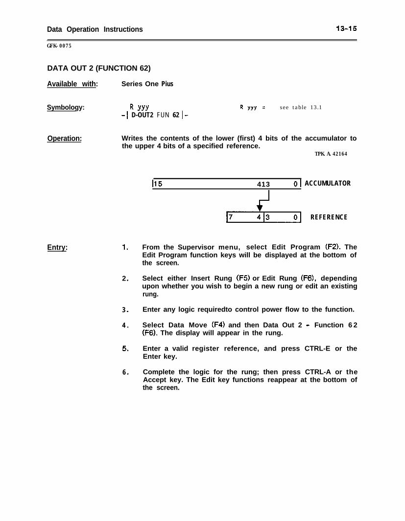
Data Operation Instructions 1345
GFK-0075
DATA OUT 2 (FUNCTION 62)
Available with: Series One Pius
Symbology: R YYY-1 D-OUT2 FUN 62 I-
R YYY = see table 13.1
Operation: Writes the contents of the lower (first) 4 bits of the accumulator tothe upper 4 bits of a specified reference.
TPK.A.42164
Entry: 1 .
2 .
3 .
4 .
5 .
6 .
115 413 01 ACCUMULATOR
p-$-y REFERENCE
From the Supervisor menu, select Edit Program (F2). TheEdit Program function keys will be displayed at the bottom ofthe screen.
Select either Insert Rung (F5) or Edit Rung (F6), dependingupon whether you wish to begin a new rung or edit an existingrung.
Enter any logic requiredto control power flow to the function.
Select Data Move (F4) and then Data Out 2 - Function 6 2(F6). The display will appear in the rung.
Enter a valid register reference, and press CTRL-E or theEnter key.
Complete the logic for the rung; then press CTRL-A or theAccept key. The Edit key functions reappear at the bottom ofthe screen.

13-16 Data Operation Instructions
GFK-0075
DATA OUT 3 (FUNCTION 63)
Available with: Series One Plus
Symbology: R YYY-1 D-OUT3 FUN 6310
R YYY = see table 13.1
Operation: Writes the contents of the lower 4 bits of the accumulator to thelower 4 bits of a specified reference.
TPK.A.42165
a 4
15 4 3 0 \
7 4 3 0.
ACCUMULATOR
REFERENCE
Entry: 1 . From the Supervisor menu, select Edit Program (FZ). TheEdit Program function keys will be displayed at the bottom ofthe screen.
2 . Select either Insert Rung (F5) or Edit Rung (F6), dependingupon whether you wish to begin a new rung or edit an existingrung.
3 . Enter any logic required to control power flow to the function.
4 . Select Logic (F6) and then Data Out 3 - Function 63 (F7). Thedisplay will appear in the rung.
5 . Enter a valid register reference, and press CTRL-E or theEnter key.
6 . Complete the logic for the rung; then press CTRL-A or theAccept key. The Edit key functions reappear at the bottom ofthe screen.
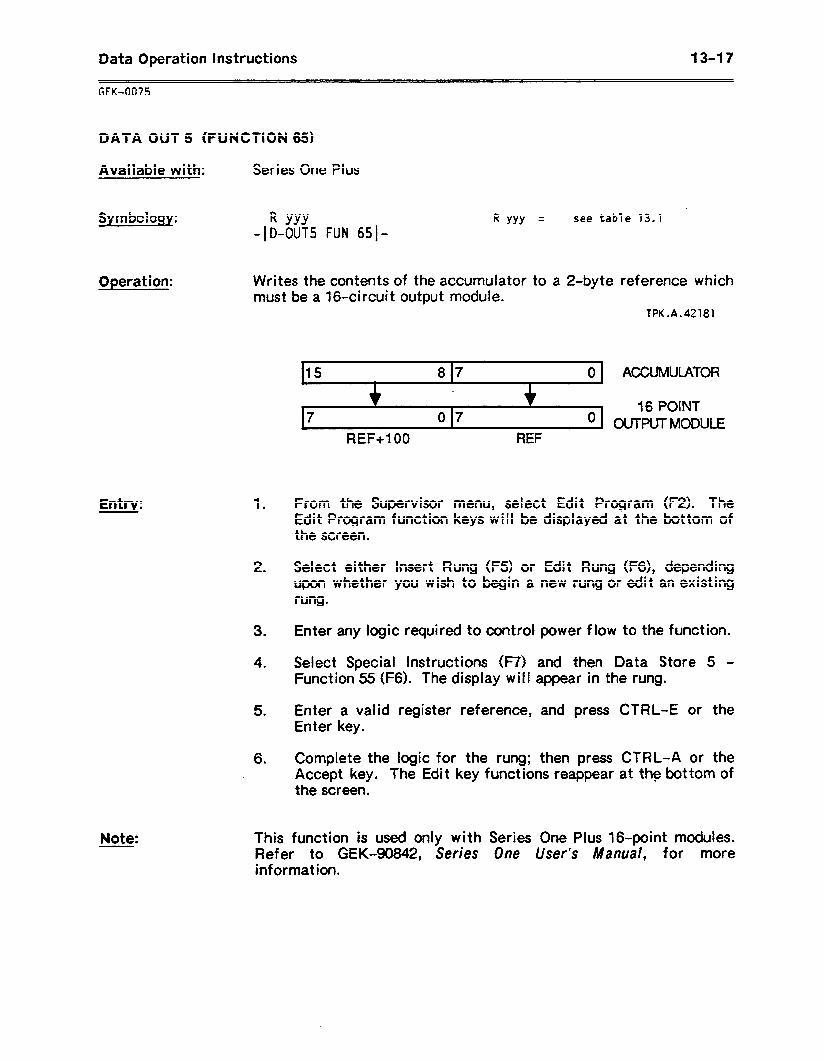
Data Operation Instructions 13-17
GFK-0075
DATA OUT 5 (FUNCTION 65)
Available with: Series One Plus
Sym bcf 0gy: R YYY -ID-OUTS FUN 6510
R YYY = see table 13.1
Opefat ion: Writes the contents of the accumulator to a 2-byte reference which must be a 16.circuit output module.
fPK.A.42181
Entry:
Note:
1 .
2 .
3 .
4 .
5 .
6 .
I15 8 17 0 1 ACCUMULATOR
07 16 POINT
’ \ OUTPUTMODULE REF+lOO REF
From the Supervisor menu, select Edit Program (F2). The Edit Program function keys wi II be displayed at the bottom of the screen.
Select either Insert Rung (F5) or Edit Rung (F6), depending upon whether you wish to begin a new rung or edit an existing rung.
Enter any logic required to control power flow to the function.
Select Special Instructions (F7) and then Data Store 5 - Function 55 (F6). The display will appear in the rung.
Enter a valid register reference, and press CTRL-E or the Enter key.
Complete the logic for the rung; then press CTRL-A or the Accept key. The Edit key functions reappear at the bottom of * the screen.
This function is used only with Series One Pius 16-point modules. Refer to GEK-90842, Series One User’s Manual, for more information.
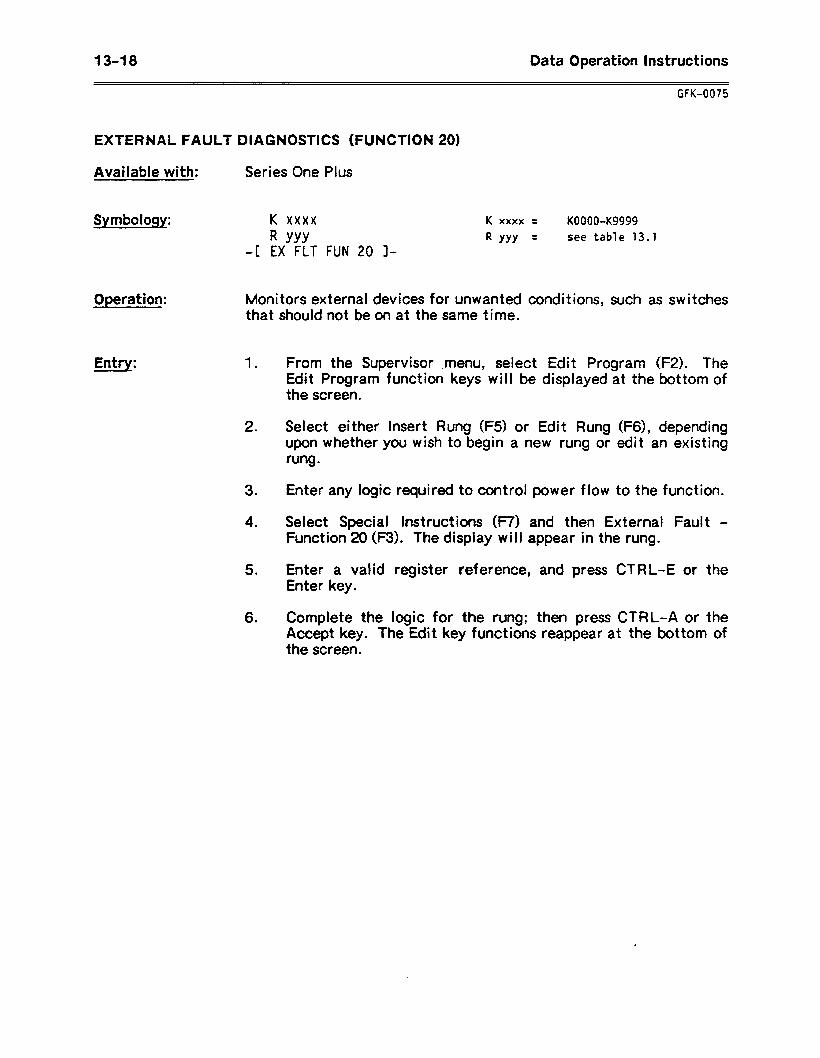
1348 Data Operation Instructions
UK-0075
EXTERNAL FAULT DIAGNOSTICS (FUNCTION 20)
Available with: Series One Plus
Symbology: K xxxx
R YYY -[ EX FLT FUN 20 I-
K xxxx = KOOOO-Kg999
R YYY = see table 13.1
Operation:
Entrv:
Monitors external devices for unwanted conditions, such as switches that should not be on at the same time.
1 .
2 .
3 .
4 .
5 .
6 .
From the Supervisor .menu, select Edit Program (FZ). The Edit Program function keys will be displayed at the bottom of the screen.
Select either Insert Rung (F5) or Edit Rung (F6), depending upon whether you wish to begin a new rung or edit an existing rung.
Enter any logic required to control power flow to the function.
Select Special Instructions (F7) and then External Fault - Function 20 (F3). The display will appear in the rung.
Enter a valid register reference, and press CTRL-E or the Enter key.
Complete the logic for the rung; then press CTRL-A or the Accept key. The Edit key functions reappear at the bottom of the screen.
Data Operation instructions 1349
SECTION 3 ARITHMETIC OPERATIONS
This section is a reference to the Arithmetic operations:
a Compare (Function 70) a Add (Function 71) 0 Subtract (Function 72) 0 Multiply (Function 73) 0 Divide (Function 74)
Table 13.2 on the following page lists the valid references for the Arithmetic operations described in this section.
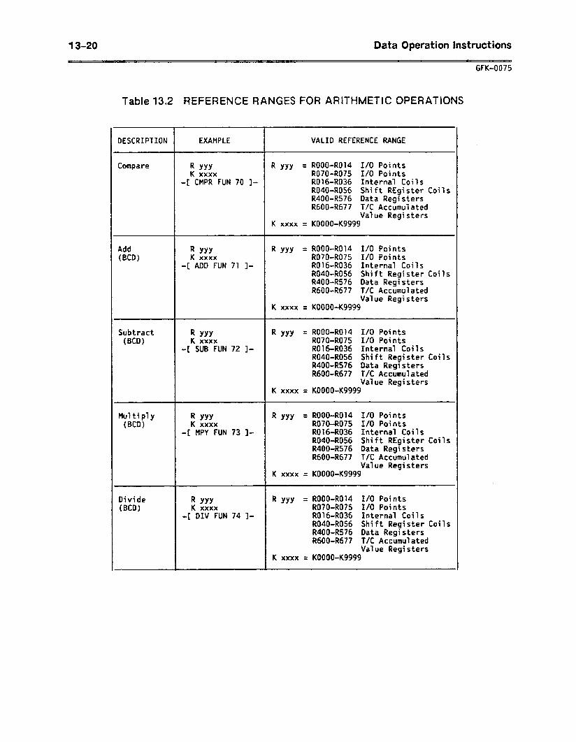
13-20 Data Operation Instructions
GFK-0075
Table 13.2 REFERENCE RANGES FOR ARITHMETIC OPERATIONS
DESCRIPTION EXAMPLE VALID REFERENCE RANGE
Compare R YYY R YYY = ROOO-R014 I/O Points K xxxx R070-R075 I/O Points
-[ CMPR FUN 70 ]- R016-R036 Internal Coils R040-R056 Shift REgi ster Coils R400-R576 Data Registers R600-R677 T/C Accumulated
Value Registers K xxxx = KOOOO-Kg999
Add (BCD)
R YYY R YYY = ROOO-R014 I/O Points K xxxx R070-R075 I/O Points
-[ ADD FUN 71 ]- R016-R036 Internal Coils R040-R056 Shift Register Coils R400-R576 Data Registers R600-R677 T/C Accumulated
Value Registers K xxxx = KOOOO-Kg999
Subtract (BCD)
R YYY R YYY = ROOO-R014 I/O Points K xxxx R070-R075 I/O Points
-[ SUB FUN 72 I- R016-R036 Internal Coils R040-R056 Shift Register Coils R400-R576 Data Registers R600-R677 T/C Accumulated
Value Registers K xxxx = KOOOO-Kg999
Mu7 ti ply (BCD)
R YYY R YYY = ROOO-R014 I/O Points K xxxx R070-R075 I/O Points
-[ MPY FUN 73 I- R016-R036 Internal Coils R040-R056 Shift REgister Coils R400-R576 Data Regi stem R600-R677 T/C Accumulated
Value Registers K xxxx = KOOOO-Kg999
Divide (BCD)
R YYY R YYY = ROOO-R014 I/O Points K xxxx R070-R075 I/O Points
-[ DIV FUN 74 l- R016-R036 Internal Coils R040-R056 Shift Register Coils R400-R576 Data Registers RdOO-R677 T/C Accumulated
Value Registers K xxxx = KOOOO-Kg999
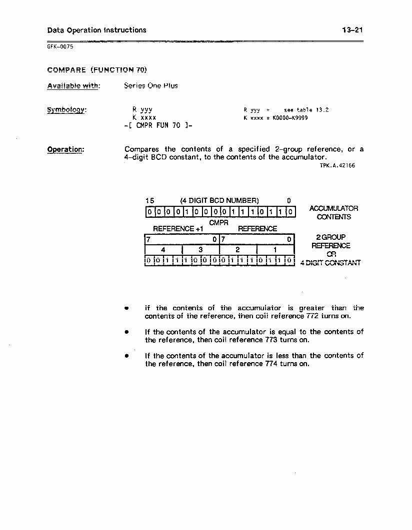
Data Operation Instructions 13-21
-- UK-0075
COMPARE (FUNCTION 70)
Available with: Series One Plus
Symbology: R YYY K xxxx
-[ CMPR FUN 70 I-
Operation:
R YYY = see table 13.2 K xxxx = KOOOO-Kg999
Compares the contents of a specified Z-group reference, or a 4-digit BCD constant, to the contents of the accumulator.
TPK.A.42166
15 (4 DIGIT BCD NUMBER) 0 \ 0
0000100001110110 ACCUMULATOR OOhENTS
CMPR REFERENCE +l REFERENCE
4
7 07 0 2 GROUP r I 4 3 2 I 1 REFERENCE L OR
10 0 1 1 1 0 0 0 0 1 1 1 0 1 1 0 \ 4 DlGtTmSTM
l If the contents of the accumulator is greater than the contents of the reference, then coil reference 772 turns on.
0 If the contents of the accumulator is equal to the contents of the reference, then coil reference 773 turns on.
0 If the contents of the accumulator is less than the contents of the reference, then coil reference 774 turns on.
13-22 9 Data Operation Instructions
UK-0075
COMPARE (FUNCTION 70) (Continued)
Entry: 1 .
2 .
3 .
4 .
5 .
6 .
From the Supervisor menu, select Edit Program (F2). The Edit Program function keys will be displayed at the bottom of the screen.
Select either Insert Rung (F5) or Edit Rung (F6), depending upon whether you wish to begin a new rung or edit an existing rung.
Enter any logic required to control power flow to the function.
Select Arithmetic (F3) and then Compare - Function 70 (F5). The Compare display appears.
Enter a valid register reference, and press CTRL-E or the Enter key.
Complete the logic for the rung; then press CTRL-A or the Accept key. The Edit key functions reappear at the bottom of the screen.
.
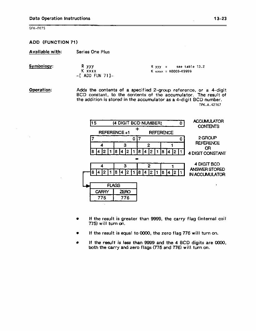
Data Operation Instructions 13-23
GFK-0075
ADD (FUNCTION 71)
Available with: Series One Plus
Symbology: R YYY K xxxx
-[ ADD FUN 71]-
Operation:
I? YYY = see table 13.2 K xxxx = KOOOO-K9999
Adds the contents of a specified 2-group reference, or a 4-digit BCD constant, to the contents of the accumulator. The result of the addition is stored in the accumulator as a 4-digit BCD number.
TPK.A.42167
15 (4 DIGIT BCD NUMBER) 0 ACCUMULATOR .
+ CONTENTS
REFERENCE +l -E
7 0 17 0
4 3 2 1
8421842184218421
.4 3 2 1
b .84218142184218421 8
2GROUP REFERENCE
OR 4 DIGIT CONSTANT
4 DIGIT BCD ANSVVER STORED IN ACCUMULATOR
If the result is greater than 9999, the carry flag (internal coi I 775) will turn on.
If the result is equal to 0000, the zero flag 776 will turn on.
t If the result is kss than 9999 and the 4 BCD digits are 0000, both the earty ati zero flags (775 and 776) will turn on.
13-24 Data Operation instructions -~~
GFK-0075
ADD (FUNCTION 71) (Continued)
Entry: 1 .
2 .
3 .
4 .
5 .
6 .
From the Supervisor menu, select Edit Program (F2). The Edit Program function keys will be displayed at the bottom of the screen.
Select either Insert Rung (F5) or Edit Rung (F6), depending upon whether you wish to begin a new rung or edit an existing rung.
Enter any logic required to control power flow to the function.
Select Arithmetic (F3) and then Add - Function 71 (Fl). The Addit ion display appears.
Enter a valid registei reference, and press CTRL-E or the Enter key.
Complete the logic for the rung; then press CTRL-A or the Accept key. The Edit key functions reappear at the bottom of the screen.
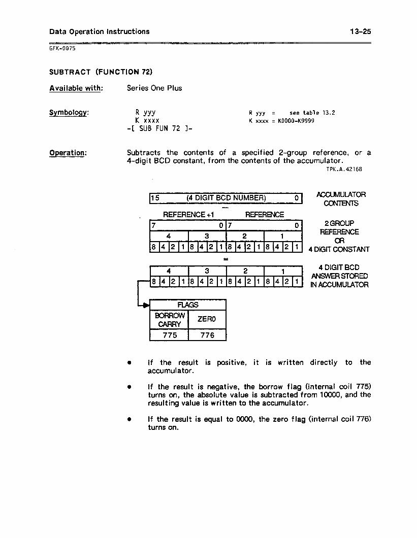
Data Operation instructions 13-25
GFK-0075
SUBTRACT (FUNCTION 72)
Available with: Series One Plus
Symbology: R YYY K xxxx
-I: SUB FUN 72 l-
Operation:
R YYY = see table 13.2 K xxxx = KOOOO-K9999
Subtracts the contents of a specified 2-group reference, or a 4-digit BCD constant, from the contents of the accumulator.
TPK.A.42168
15 (4 DIGIT BCD NUMBER) 0 I \
1 REFERENCE +1 - REFERENCE
F 017 I I
4 3 2 1
8421842184218421 e l
4 3 2 a
1 L . ~842181421842181421 I
4
lU%UMULATOR itNTs
2GROUP FWERENCE
a? DIGIT COhlSTANT
4 DIGIT BCD ANswERsroRED IN ACCUMULATOR
0 If the result is positive, it is written directly to the accumulator.
0 If the result is negative, the borrow flag (internal coil 775) turns on, the absolute value is subtracted from 10000, and the resulting value is written to the accumulator.
0 If the result is equal to 0000, the zero flag (internal coil 776) tufns on.
13-26 Data Operation Instructions
GFK-0075
SUBTRACT (FUNCTION 72) (Continued)
Entry: 1 .
2 .
3 .
4 .
5 .
6 .
From the Supervisor menu, select Edit Program (FZ). The Edit Program function keys will be displayed at the bottom of the screen.
Select either Insert Rung (F5) of Edit Rung (F6), depending upon whether you wish to begin a new rung or edit an existing rung.
Enter any logic required to control power flow to the function.
Select Arithmetic (F3) and then Subtract - Function 72 (FZ). The Subtraction display appears.
Enter a valid register Enter key.
reference, and press CTRL-E or the
Complete the logic for the rung; then press CTRL-A or the Accept key. The Edit key functions reappear at the bottom of the screen.
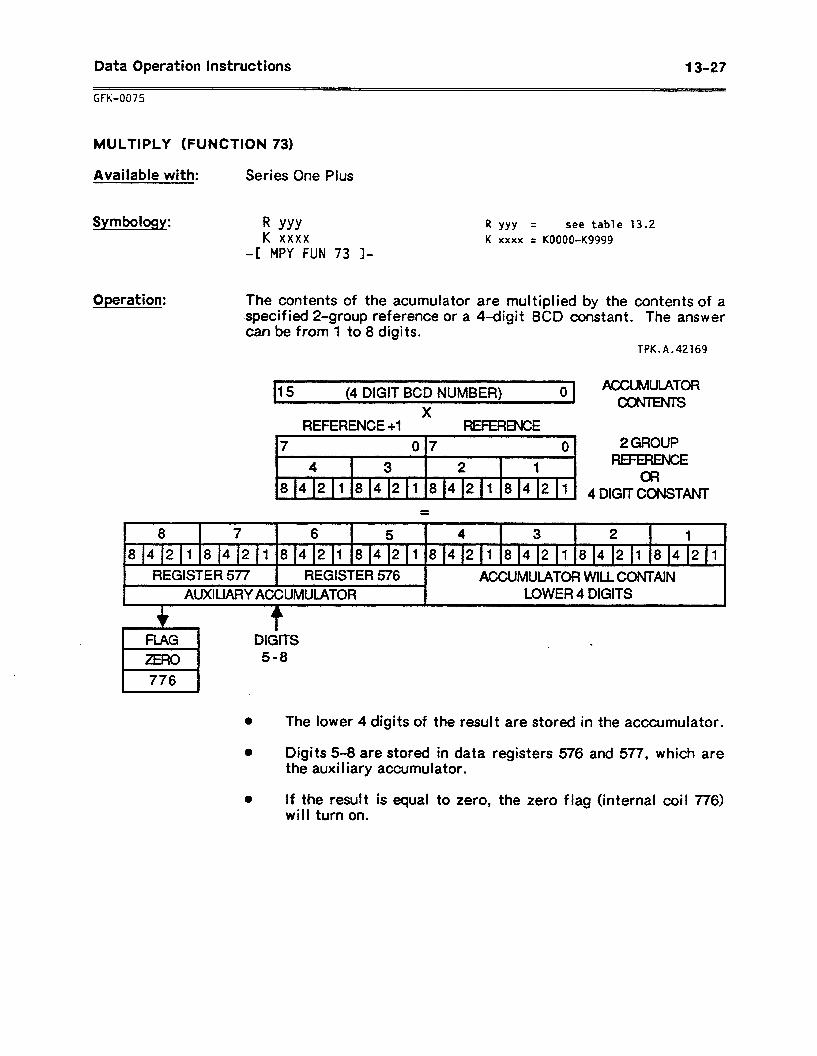
Data Operation instructions 13-27
MULTIPLY (FUNCTION 73)
Available with: Series One Plus
Symbology: R YYY K xxxx
-I MPY FUN 73 I-
R YYY = see table 13.2 K xxxx = KOOOCbK9999
Operation: The contents of the acumulator ate multiplied by the contents of a specified 2-group reference or a 4-digit BCD constant. The answer can De rrom 10 u algrrs.
TPK.A.42169
b
15 (4 DIGIT BCD NUMBER) 0’ ACCUMULATOR
V ItJws
REFERENCE +l REFERENCE 7 07 0 2 GROUP
1 4 3 2 1 REFERENCE 1 OR 8 412 1 8 4 2 1 8 4 211 8 4 2 1 A 4DlGmmTANJ-
8 7 6 5 4 3 2 1
r 84218)42184,2184218421842184218421
1 REGISTER 577 1 REGISTER 576 1 ACCUMULATOR WILLCONTAIN
I AUXIUARY AC%UMUlATaR - I LOWER 4 DIGITS
0 The lower 4 digits of the result are stored in the acccumuiator.
0 Digits 5-8 are stored in data registers 576 and 577, which are the auxi I iary accumulator.
0 If the result is equal to zero, the zero flag (internal coil 7%) will turn on.
13-28 Data Operation Instructions
GFK-0075
MULTIPLY (FUNCTION 73) (Continued)
Entry: 1 .
2 l
3 .
4 .
5 .
6 l
From the Supervisor menu, select Edit Program (FZ). The Edit Program function keys will be displayed at the bottom of the screen.
Select either Insert Rung (F5) or Edit Rung (F6), depending upon whether you wish to begin a new rung or edit an existing rung.
Enter any logic required to control power flow to the function.
Select Arithmetic (F3) and then Multiply - Function 73 (F3). The Multiplication display appears.
Enter a valid register reference, and press CTRL-E or the Enter key.
Complete the logic for the rung; then press CTRL-A or the Accept key. The Edit key functions reappear at the bottom of the screen.
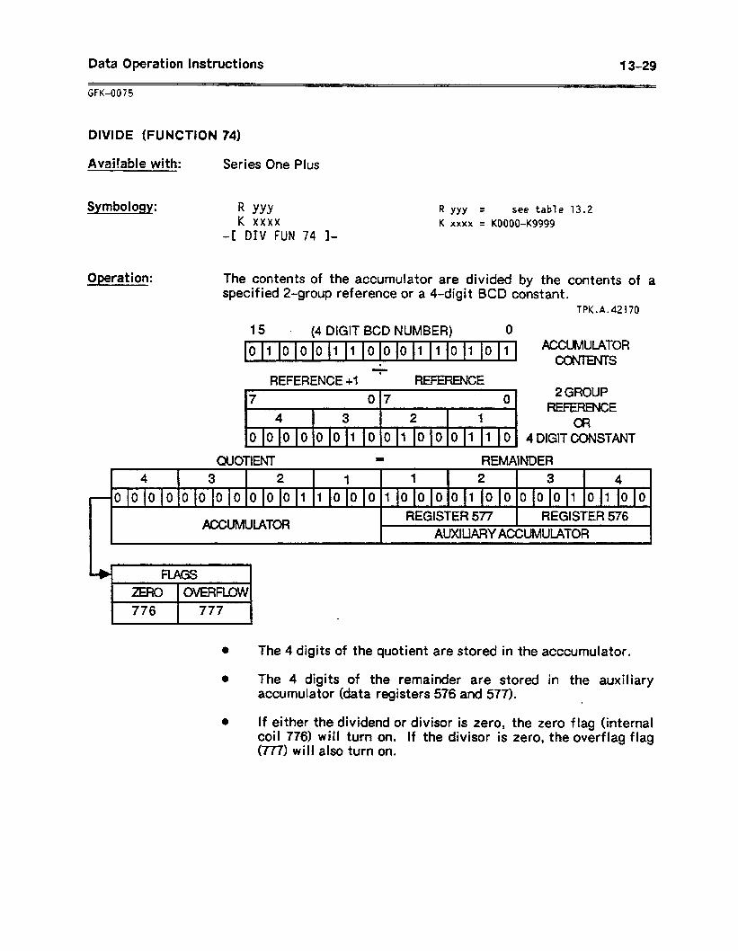
Data Operation Instructions 13-29
GFK-0075
DIVIDE (FUNCTION 74)
Avai!able with: Series One Plus
Symbology: R YYY K xxxx
4 DIV FUN 74 I-
R YYY = see table 13.2 K xxxx = KOOOO-Kg999
ODeration: The contents of the accumulator are divided by the contents of a specified 2-group reference or a 4-digit BCD constant.
fPK.A.42170
15 - (4 DIGIT BCD NUMBER) 0
01000110001.10101 ACCUMULATOR
. CONIENTS
REFERENCE +1 ’ REFERENCE \7 1 07 0 2 GROUP r 7 I REFERENCE
4 3 2 1 , , a? 0 0 010 0 0 1 0 0 1 0 0 0 1 1 0 4DlGlTCONSTANT
QUOTlENT - REMAINDER
4 3 2 1 1 2 3 4 1 0000000000011000100001000001010~0
ACCUMULATOR REGISTER 577 REGISTER 576 1 1 AUXILIARY ACCUMULATOR
776 I 777
l The 4 digits of the quotient are stored in the acccumulator.
0 The 4 digits of the remainder are stored in the auxiliary accumulator (data registers 576 and 577). .
l If either the dividend or divisor is zero, the zero flag (internal coil 776) will turn on. If the divisor is zero, the overf lag flag (777) will also turn on.
13-30 Data Operation Instructions
GfK-0075
DIVIDE (FUNCTION 74) (Continued)
Entry: 1 .
2 .
3 .
4 .
5 .
6 .
From the Supervisor menu, select Edit Program (F2). The Edit Program function keys will be displayed at the bottom of the screen.
Select either Insert Rung (FS) or Edit Rung (F6), depending upon whether you wish to begin a new rung or edit an existing rung l
Enter any logic required to control power flow to the function.
Select Arithmetic (F3) and then Divide - Function 74 (F4). The Division display appears.
Enter a valid register reference, and press CTRL-E or the Enter key.
Complete the logic for the rung; then press CTRL-A or the Accept key. The Edit key functions reappear at the bottom of the screen.
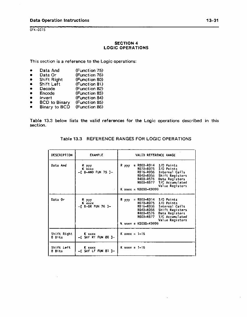
Data Operation Instructions 13-31
SECTION 4 LOGIC OPERATIONS
This section is a reference to the Logic operations:
Data And (Function 75) Data Or (Function 76) Shift Right (Function 80) Shift Left (Function 81) Decode (Function 82) Encode (Function 83) invert (Function 84) BCD to Binary (Function 85) Binary to BCD (Function 86)
Table 13.3 below lists the valid references for the Logic operations described in this sect ion.
Table 13.3 REFERENCE RANGES FOR LOGIC OPERATIONS
DESCRIPTION EXAMPLE VALID REFERENCE RANGE -
Data And R YYY R YYY = ROOO-R014 I/O Points K xxxx R070-R075 I/O Points
-[ D-AND FUN 75 ]- R016-R036 Internal Coils R040-R056 Shift Registers R400-R576 Data Registers R600-R677 T/C Accumulated
Value Registers . K xxxx = KOOOO-K9999
Data Or R YYY R YYY = ROOO-R014 I/O Points K xxxx R070-R075 I/O Points
-[ D-OR FUN 76 I- R016-R036 Internal Coils R040-R056 Shift Registers R400-R576 Data Registers R600-R677 T/C Accumulated
I
Value Registers K xxxx = KOOOO-K9999
Shift Right K xxxx K xxxx = l-16 8 Bits -[ SHF RT FUN 80 ]-
Shift Left K xxxx K xxxx = 1-16 8 Bits -[ SHF LF FUN 81 I-
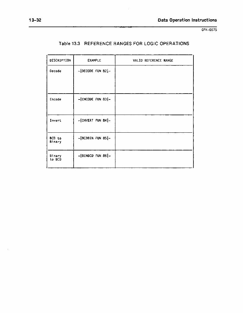
13-32 Data Operation Instructions
GFK-0075
Table 13.3 REFERENCE RANGES FOR LOGIC OPERATIONS
DESCRIPTION EXAMPLE VALID REFERENCE RANGE
Decode -IDECODE FUN 821.
Encode -1 ENCODE FUN 83j-
Invert -IINVERT FUN 84-
BCD to Binary
-~BCDBIN FUN 851-
Binary to BCD
-IBINBCD FUN 861.
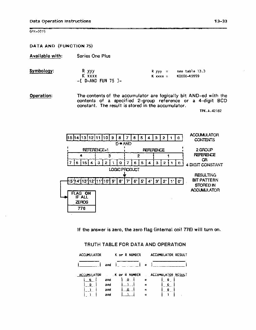
Data Operation Instructions 13-33
GfK-0075
DATA AND (FUNCTION 75)
Available with: Series One Plus
Symbology: R YYY K xxxx
-I: D-AND FUN 75 I-
R YYY = see table 13.3 K xxxx = KOOOO-Kg999
Operation: The contents of the accumulator are logically bit AND-ed with the contents of a specified 2-group reference or a 4-digit BCD constant. The result is stored in the accumulator.
TPK.A.42182
15 14 13112 ’
11 IO 9 8 17 6 5 4 3 2 I 0 ACCUMUlATOR
l CONTENTS
I I
DaAND
REFERENCE+1 I I t I 2GRoUP
4 3 2 1 I 1 76154321076543210
\ OR
1 4 DIGIT CONSTANT LOGICPRODUCT
4 RESULTING ,&,4’,3“,2 11’10’ 9’ 8’17’ 6’ 5’ 4’ 3’ 2’1 1’ 0’ _ Bm PAmERN * 1
STORED IN ACCUMULATOR
.
If the answer is zero, the zero flag (internal coil 776) will turn on.
TRUTH TABLE FOR DATA AND OPERATION
ACCUMULATOR K or R NUMBER ACCUtlULATOR RESULT
I I and I I = I I
ACCUHULATOR IIC or R NUWER ACCUMULATOR RESULT
i&f and 001 = IOI lol and 1-l = i--oI 111 and IA-I = lOI l-l and Ill = I 1 I
13-34 Data Operation Instructions
GFK-0075
DATA AND (FUNCTION 75) (Continued)
Entry: 1 .
2 .
3 .
4 .
5 .
6 .
From the Supervisor menu, select Edit Program (F2). The Edit Program function keys will be displayed at the bottom of the screen.
Select either Insert Rung (F5) or Edit Rung (F6), depending upon whether you wish to begin a new rung or edit an existing rung.
Enter the logic required to control power flow to the function.
Select Logic (F6) and then D-AND - Function 75 (Fl). The Logical AND display appears.
Enter a valid register reference, and press CTRL-E or the Enter key.
Complete the logic for the rung; then press CTRL-A or the Accept key. The Edit key functions reappear at the bottom of the screen.
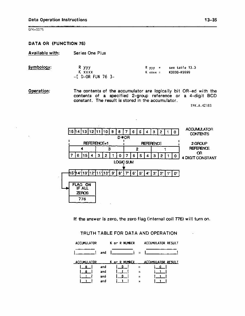
Data Operation Instructions 13-35
DATA OR (FUNCTION 76)
Available with: Series One Plus
Symbology: R YYY K xxxx
-t D-OR FUN 76 l-
R YYY = see table 13.3 K xxxx = KOOOO-Kg999
Operation: The contents of the accumulator are logically bit OR-ed with the contents of a specified 2-group reference or a 4-digit BCD constant. The result is stored in the accumulator.
TPK.A.42183
A 15 14 13 12 11 10 9 8 7 6 5 4 3 2 1 0
ACCUMULATOR / . CON?ENTS
D .OR I I REFERENCE+1
I I I I 2GROUP ,
4 3 2 1 , 7 6 15 4 3 2 1 1 0 7 6 5 4 3 2 1 0
OR . 1 4 DlGITCONSTANT
LOGIC SUM
5’14’ 13’ 12’ 13’10’ 9’ 8’ 7’ 6’ 5’ 4’ 3’ 2’ 1’ 0’ \ .
FLAG ON IF ALL
\
ZEROS
776
Of the answer is zero, the zero flag (internal coil 776) will turn on.
TRUTH TABLE FOR DATA AND OPERATION -
ACCUMULATOR K or R NUMBER ACCUMULATOR RESULT
I I and 1 I = I I
ACCUMULATOR K or R NWBER ACCUMUl ATCIR =WLT
lol and lol = IOI Iol and IrI = irl am! lOI =
111 111
111 and IL1 = - I 1 I

13-36 Data Operation Instructions
GFK-0075
DATA OR (FUNCTION 76) (Continued)
Entry: 1 .
2 .
3 .
4 .
5 .
6 .
From the Supervisor menu, select Edit Program (F2). The Edit Program function keys will be displayed at the bottom of the screen.
Select either Insert Rung (FS) or Edit Rung (F6), depending upon whether you wish to begin a new rung or edit an existing rung l
Enter the logic required to control power flow to the function.
Select Logic (F6) and then D-OR - Function 76 (F2). The Logical OR display appears.
Enter a valid register reference, and press CTRL-E or the Enter key.
Complete the logic for the rung; then press CTRL-A or the Accept key. The Edit key functions reappear at the bottom of the screen.
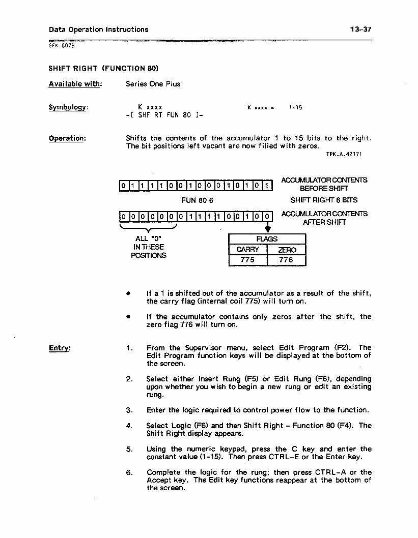
Data Operation Instructions 13-37
GFK-0075
SHIFT RIGHT (FUNCTION 80)
Available with: Series One Plus
Symbology: K xxxx -C SHF RT FUN 80 I-
K xxxx = l-15
Operation: Shifts the contents of the accumulator 1 to 15 bits to the right. The bit positions left vacant are now filled with zeros.
TPK.A.42171
/ ,o 111 11 0 0 10 0 0110 1011
ACCUMULATORS BEFORE SHIFT
FUN 80 6 SHIK RIGHT 6 BITS
b
00000~00/111100100 ' ACCUMULATORWNTENTS r l AFTER SHIFI-
ALL “0” IN THESE
PosmoNs
Entry:
0
1 .
2 .
3 .
4 .
5 .
6 .
If a 1 is shifted out of the accumulator as a result of the shift, the carry flag (internal coil 775) will turn on.
If the accumulator contains only zeros after the shift, the zero flag 776 will turn on.
From the Supervisor menu, select Edit Program (F2). The Edit Program function keys will be displayed at the bottom of the screen. .
Select either Insert Rung (F5) or Edit Rung (F6), depending upon whether you wish to begin a new rung or edit an existing rung.
Enter the logic required to control power flow to the function.
Setecf Logic (F6) and then Shift Right - Function 80 (F4). The Shift Right display appears.
Using the numeric keypad, press the C key and enter the constant value (l-15). Then press CTRL-E or the Enter key.
Complete the logic for the rung; then press CTRL-A or the Accept key. The Edit key functions reappear at the bottom of the screen.
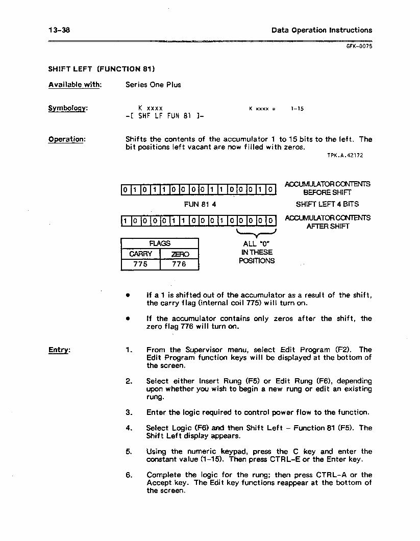
13-38 Data Operation Instructions
GFK-0075
SHIFT LEFT (FUNCTION 81)
Available with: Series One Plus
Symbology: K xxxx -I: SHF LF FUN 81 l-
K xxxx = l-15
Operation: Shifts the contents of the accumulator 1 to 15 bits to the left. The bit positions left vacant are now filled with zeros.
TPK.A.42172
\ 0101100001100010
4 AUXMUlATOFWWENTS
/ \ BEFORE SHIFT .
FUN 81 4 SHIFT LEFT 4 BITS
. 1000011000100000 A ACCUMUtAToRCOfWENTS
Entry:
. l
0
1 .
2 .
3 .
4 .
5 .
6 .
If a 1 is shifted out of the accumulator as a result of the shift, the carry flag (internal coi I 775) will turn on.
If the accumulator contains only zeros after the shift, the zero flag 776 will turn on.
From the Supervisor menu, select Edit Program (FZ). The Edit Program function keys will be displayed at the bottom of the screen.
Select either Insert Rung (F5) or Edit Rung (F6), depending upon whether you wish to begin a new rung or edit an existing rung.
Enter the logic required to control power flow to the function.
Select Logic (F6) WK! then Shift Left - Function 81 (F5). The Shift Left display appears.
Using the numeric keypad, press the C key and enter the constant value (I-15). Then press CTRL-E or the Enter key.
Complete the logic for the rung; then press CTRL-A or the Accept key. The Edit key functions reappear at the bottom of the screen.
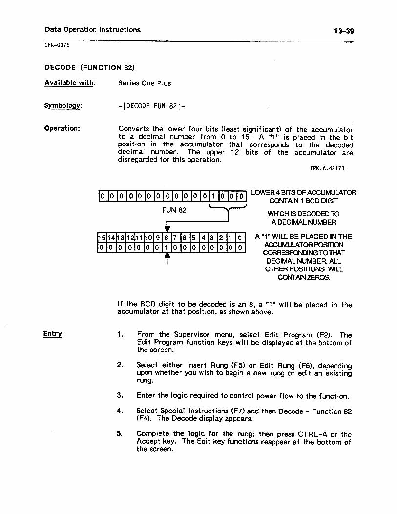
Data Operation Instructions 13-39
GFK-0075
DECODE (FUNCTION 82)
Available with: Series One Plus
Symbology: - 1 DECODE FUN 82 I-
Operation: Converts the lower four bits (least significant) of the accumulator to a decimal number from 0 to 15. A **V is placed in the bit position in the accumulator that corresponds to the decoded .decimal number. The upper 12 bits of the accumulator are disregarded for this operation.
TPK.A.42173
Entry:
. 0000~000000001(000 ’ LOWER 4 BITS OF ACCUMULATOR
CONTAIN 1 BCD DIGIT
FUN 82
/
151413121110 9 8 7 6 5 4 3 2 1 0 1 0000000100000000
t
WHICH IS DECODED TO A DECIMAL NUMBER
A “1” WILL BE PLACED IN THE ACCUMULATOR PosmoN CORRESPONDlNG~OTHAT
DECIMAL NUMBER. AU OTHER POSITIONS WILL
CONTAINZEROS.
If the BCD digit to be decoded is an 8, a “1 ‘I will be placed in the accumulator at that position, as shown above.
1 .
2 .
3 .
4 .
5 .
From the Supervisor menu, select Edit Program (F2). The Edit Program function keys will be displayed at the bottom of the screen.
Select either Insert Rung (F5) or Edit Rung (F6), depending upon whether you wish to begin a new rung or edit an existing rung.
Enter the logic required to control power flow to the function.
Select Special Instructions (F7) and then Decode - Function 82 (F4). The Decode display appears.
Complete the logic for the rung; then press CTRL-A or the Accept key. The Edit key functions reappear at the bottom of the screen.
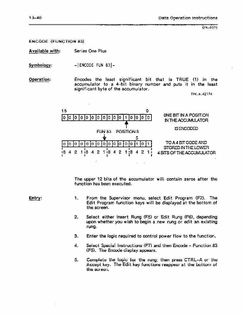
13-40 Data Operation instructions
GFK-0075
ENCODE (FUNCTION 83)
Available with: Series One Plus
Symbology: -1 ENCODE FUN 8310
Operation: Encodes the least significant bit that is TRUE (1) in the accumulator to a $-bit binary number and puts it in the least significant byte of the accumulator.
TPK.A.42174
Entry:
15 0 . 00000~00000010000
ONE BIT IN A POSITION I IN THE ACCUMULATOR
FUN 83 POSITION 5 lSENcoDED
5 I
000~000000000~0101 TO A 4 BlT CODE AND I :8
STORED INTHE LOWER 4 2 1 :8 4 2 118 4 4 2 1
D 1 1 2 118 i 4B~SOfTHEA~UMU~TOR
The upper 12 bits of the accumulator will contain zeros after the function has been executed.
1 .
2 .
3 .
4 .
5 l
From the Supervisor menu, select Edit Program (F2). The Edit Program function keys will be displayed at the bottom of the screen.
Select either Insert Rung (F5) or Edit Rung (F6), depending upon whether you wish to begin a new rung or edit an existing rung.
Enter the logic required to control power flow to the function.
Select Special Instructions (F7) and then Encode - Function 83 (F5). The Encode display appears.
Complete the logic for the rung; then press CTRL-A or the accept key. The Edit key functions reappear at the bottom of the screen.
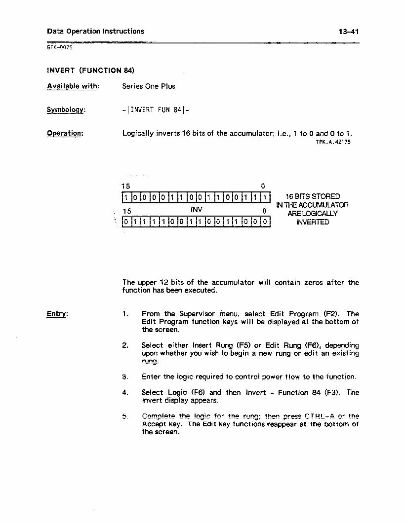
Data Operation instructions 13-41
INVERT (FUNCTION 841
Available with: Series One Plus
Symboiogy: -IINVERT FUN 8410
Operation: Logically inverts 16 bits of the accumulator; i.e., 1 to 0 and 0 to 1. TPK.A.42175
Entry:
15 0 . . 1000011001100111 16 BITS STORED
IN THE ACCUMULATOR ’ , 15 0
INV . ARELOGICALLY
!_ 0 1 1 111 0 0 1 1 0 011 1 0 0 0 INVERTED r \
The upper 12 bits of the accumulator will contain zeros after the function has been executed.
1 . From the Supervisor menu, select Edit Program (F2). The Edit Program function keys will be displayed at the bottom of the screen.
2 . Select either Insert Rung (FS) or Edit Rung (F6), depending upon whether you wish to begin a new rung or edit an existing rung.
3 . Enter the logic required to control power flow to the function.
4 . Select Logic (F6) and then Invert - Function 84 (F3). The Invert display appears.
5 . Complete the logic for the rung; then press CTRL-A or the Accept key. The Edit key functions reappear at the bottom of the screen.
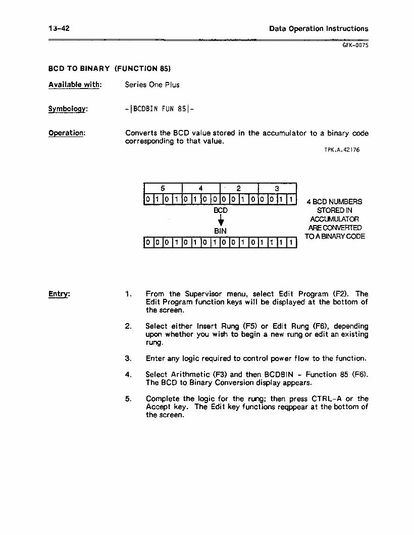
13-42 Data Operation instructions
GFK-0075
BCD TO BINARY (FUNCTION 85)
Available with: Series One Plus
Symboiogy: +CDBIN FUN 851-
Operation: Converts the BCD value stored in the accumulator to a binary code corresponding to that value.
TPK.A.42176
Entrv:
1 -r- ~~ ~~- = ~~ -~-
5 4 . 2 3 1 0101010000100011
v BCD
+ BIN
l
0001010100101111 v \
4 BCD NUMBERS STORED IN
AGWMUIATOR ARECONVERTED
TO A BINARY CODE
1 . From the Supervisor menu, select Edit Program (F2). The Edit Program function keys will be displayed at the bottom of the screen.
2 . Select either Insert Rung (F5) or Edit Rung (F6), depending upon whether you wish to begin a new rung or edit an existing rung.
3 . Enter any logic required to control power flow to the function.
4 . Select Arithmetic (F3) and then BCDBIN - Function 85 (F6). The BCD to Binary Conversion display appears.
5 . Complete the logic for the rung; then press CTRL-A or the Accept key. The Edit key functions reqppear at the bottom of the screen.
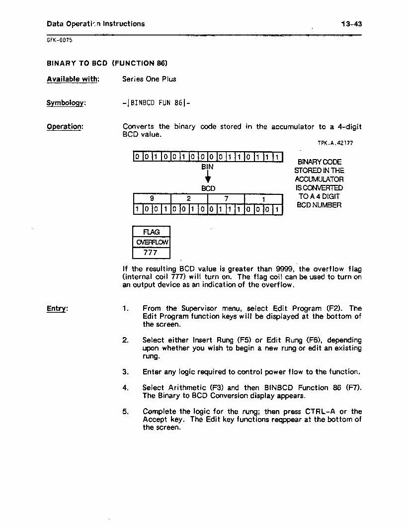
Data Operatkq Instructions 13-43 ,
GFK-0075
BINARY TO BCD (FUNCTION 86)
Available with: Series One Pius
Symboloqy: -1 BINBCD FUN 861-
Operation: Converts the binary code stored in the accumulator to a 4-digit BCD value.
TPK.A.42177
Entry:
0 011 lo 0 1 0 0 0 0 111 lo 111 1 /
9 2 7 1
1001001001110001
BINARYCODE STORED IN THE ACCWMATOR lSCONI/ERTED TO A 4 DIGIT BCD NUMBER
RAG
H_ * CWEFFLW
777
If the resulting BCD value is greater than 9999, the overflow flag (internal coil 777) will turn on. The flag coil can be used to turn on an output device as an indication of the overflow.
1 .
2 .
3 .
4 .
5 .
From the Supervisor menu, select Edit Program (F2). The Edit Program function keys will be displayed at the bottom of the screen.
Select either Insert Rung (F5) or Edit Rung (F6), depending upon whether you wish to begin a new rung or edit an existing rung.
Enter any logic required to control power flow to the function.
Select Arithmetic (F3) and then BINBCD Function 86 (F7). The Binary to BCD Conversion display appears.
Complete the logic for the rung; then press CTRL-A or the Accept key. The Edit key functions reqppear at the bottom of the screen.

Appendix A: Setup information A-1
GFK-0075
APPENDIX A SETUP INFORMATION
The following pages provide information needed to connect the Workmaster computer and other computers to the Series One or Series One Plus PLC and peripherals, such as an external disk drive or printer. included are port pin-outs, vendor part numbers for connectors and cables (GE Fanuc - NA cable numbers where applicable), and wiring diagrams.
This appendix contains the following sections:
Page
Section 1. Workmaster Factory-Installed Cards: Combination Adapter Card Diskette Drive Adapter Card Color/Graphics Monitor Adapter Card
Section 2. User-Installed Option Cards: 384K RAM Card Asynchronous/Joystick Card
Section 3. Connecting the Workmaster Computer to the Series One/One Plus PLC:
Section 4. Connectiner the Workmaster II Computer to the Series One/One Plus PLC:
Section 5. Connectina the IBM Personal Cornouter
A-2 A-6 A-7
A-10 A-10
A-14
A-20
to the Series One/One Pius PLC: A-21
_ Modems: Section 6 explains how to connect and use modems with Logicmaster 1 F soft ware.
Section 7. Multidrop Configuration: The Logicmaster 1 F system supports multidrop configuration up to eight CPUs and QCUs. Section 7 explains the hardware required and provides a cable drawing.
NOTE
The vendor part numbers for connector hardware and cables included in this appendix are for reference only. Inclusion of these part numbers is neither an endorsement nor a recommendation for their use.
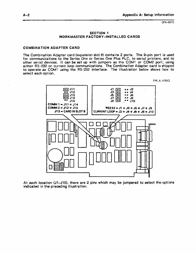
A-2 Appendix A: Setup Information
GFK-0075
SECTION 1 WORKMASTER FACTORY-INSTALLED CARDS
COMBINATION ADAPTER CARD
The Combination Adapter card (expansion slot 8) contains 2 ports. The g-pin port is used for communications to the Series One or Series One Plus PLC, to serial printers, and to other serial devices. It can be set up with jumpers as the COMl or COM2 port, using either M-232 or current loop communications. The Combination Adapter card is shipped to operate as COMl using the W-232 interface. The illustration below shows how to select each opt ion.
TPK.A.41043
177~311 0. J12 l . J13
6 l * 314
CotUIMl =Jll+J14 coMM2=J12+J15
313 = CARD IN SLdT 8
JllZl l oJ2 . l * 34 l * 36
37 l . .. JS I 39 tl l @ -. .a 310
RS232=31+ J3+ J5+ J7+ J9 CURRENT100P=32+34+36+38+310
7-
At each location (Jl-J15), there are 2 pins which may be jumpered to select the options indicated in the preceding illustration.
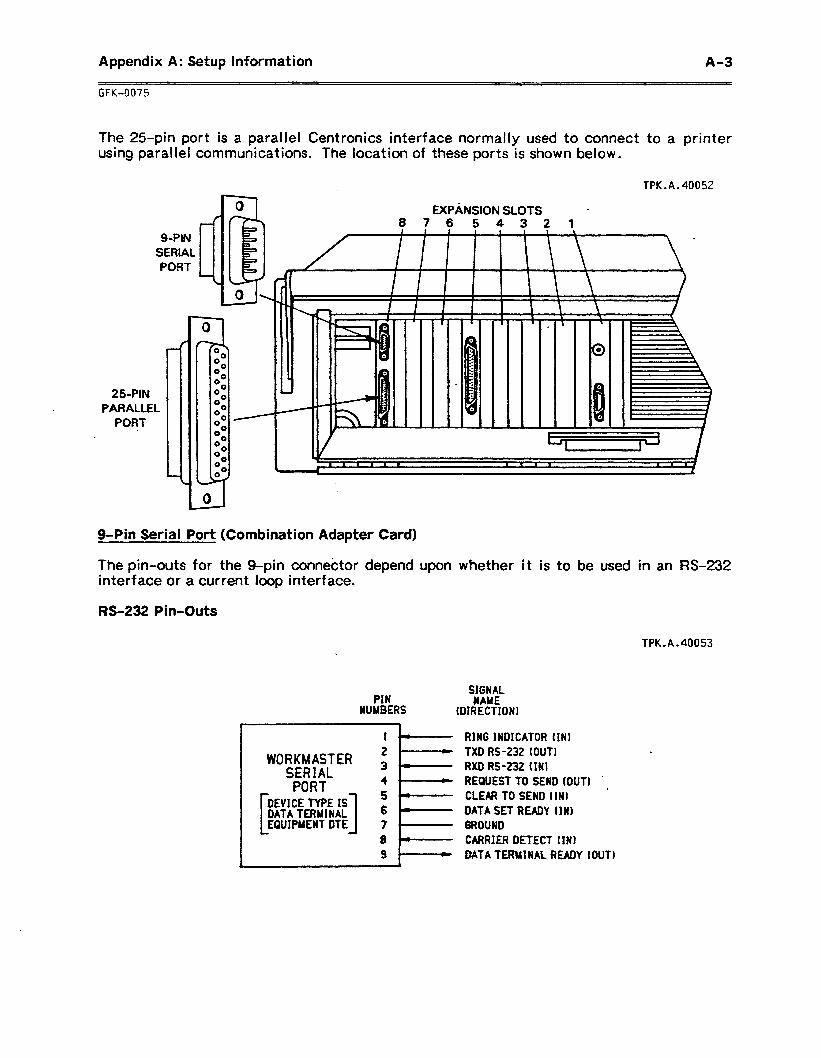
Appendix A: Setup Information A-3
GFK4075
The 25-pin port is a parallel Centronics interface normally used to connect to a printer using parallel communications. The location of these ports is shown below.
TPK.A.40052
EXPANSION SLOTS l
87654321
S-PIN SERIAL PORT
25PIN PARALLEL
PORT .
g-Pin Serial Port (Combination Adapter Card)
The pin-outs for the g-pin connector depend upon whether it is to be used in an RS-232 interface or a current loop interface.
M-232 Pin-Outs
TPK.A.40053
SIGNAL UAME
IDIRECTION
RING INDICATOR tINl TXD RS-232 (OUT1 .
RXD RS-232 (INI REQUEST TO SEND Wfl
WORKMASTER SERIAL PORT c
CLEAR TO SEND IIN1 DATA SET READY (IN) GROUND CARRIER DETECT (INI MTA TEftWINAL READY tOUTI
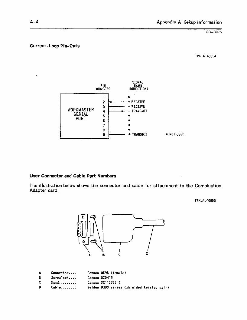
A-4 Appendix A: Setup information
GFK-0075
Current-Loop Pin-Outs
TPK.A.40054
SIGNAL PIN YAME
NUMBERS (DIRECTKINI
I 2 t)----- +RECEIVE
WORKMASTER : SERIAL
PORT 5 6
-RECEIVE -TRANSMIT + . +
7
l- +
8 +
9 + TRANSMIT + NOT USED
User Connector and Cable Part Numbers
The illustration below shows the connector and cable for attachment to the Combination Adapter card.
TPK.A.40055
A ConnectQr.. . * Cannon DE9S ( femal e) B Screwlock.. . . Cannon 020419
C Hood . . . . . . . . . Cannon DE1109634 D Cab1 e . . . . . . . . Belden 9300 series (shielded twisted pair)
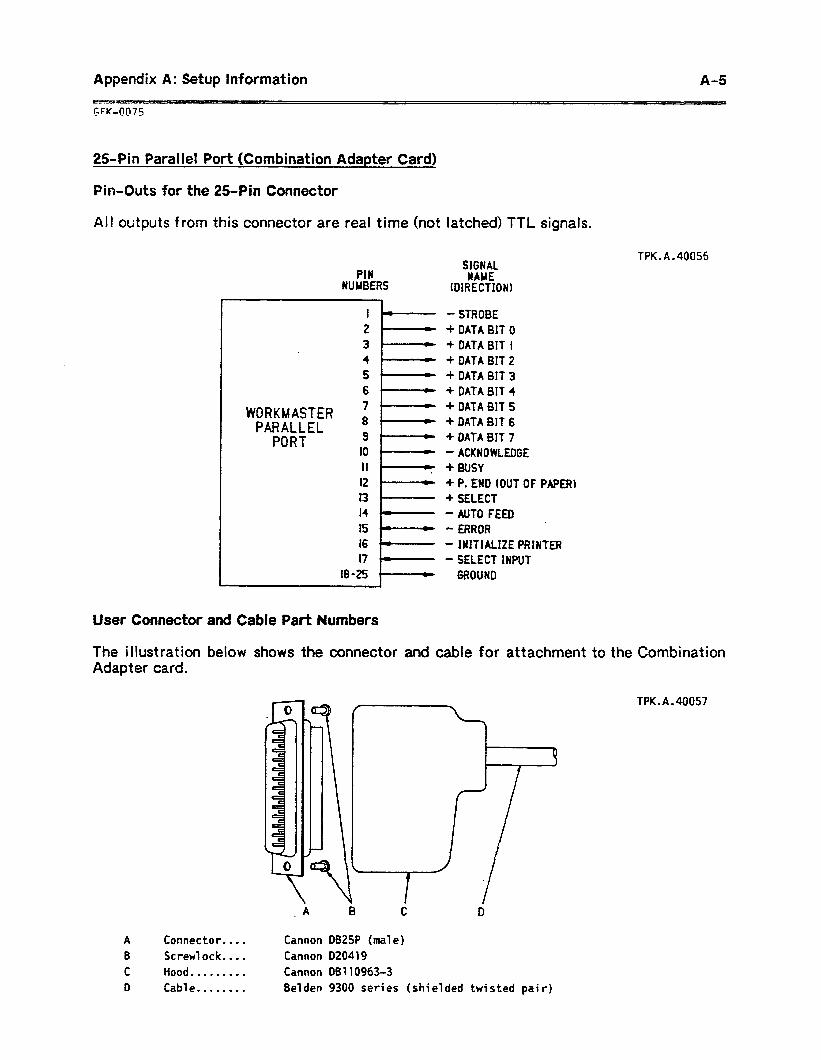
Appendix A: Setup Information W- GFK-QQ75
A-5
25.Pin Parallel Port (Combination Adapter Card)
Pin-Outs for the 25.Pin Connector
All outputs f ram this connector are real time (not
PIN NUMBERS
IL 2 ' 3- . 4 - 5+ 6 r
WORKMASTER 8’ L >
PARALLEL PORT 3
IO - II - * 12 ‘- 13 I4 v 15 - I6 r- 17 I-
18-25 I-
latched) TTL signals.
TPK.A.40056 SIGNAL NAME
IDIRECTIONl
-STROBE + DATA 0110 + DATA BIT 1 + DATA BIT 2 + DATA BIT 3 + DATA 817 4 + DATA MT 5 + DATA BIT 6 + DATA 01T 7 - ACKNOWLEDGE + BUSY + P. END (OUT OF PAPER) + SELECf - AUTO FEED - ERROR - INITIALIZE PRINTER - SELECT INPUT
GROUND
User Connector and Cable Part Numbers
The illustration below shows the connector and cable for attachment to the Combination Adapter card.
A Connector.. . . B Screwlock.. . . C Hood . . . . . . . . . D Cab1 e . . . . . . . .
_ A 0 C D
Cannon DB25P (ma1 e) Cannon 020419
Cannon 08110963-3
Be1 den 9300 series (shielded twisted pai r)
TPK.A.40057
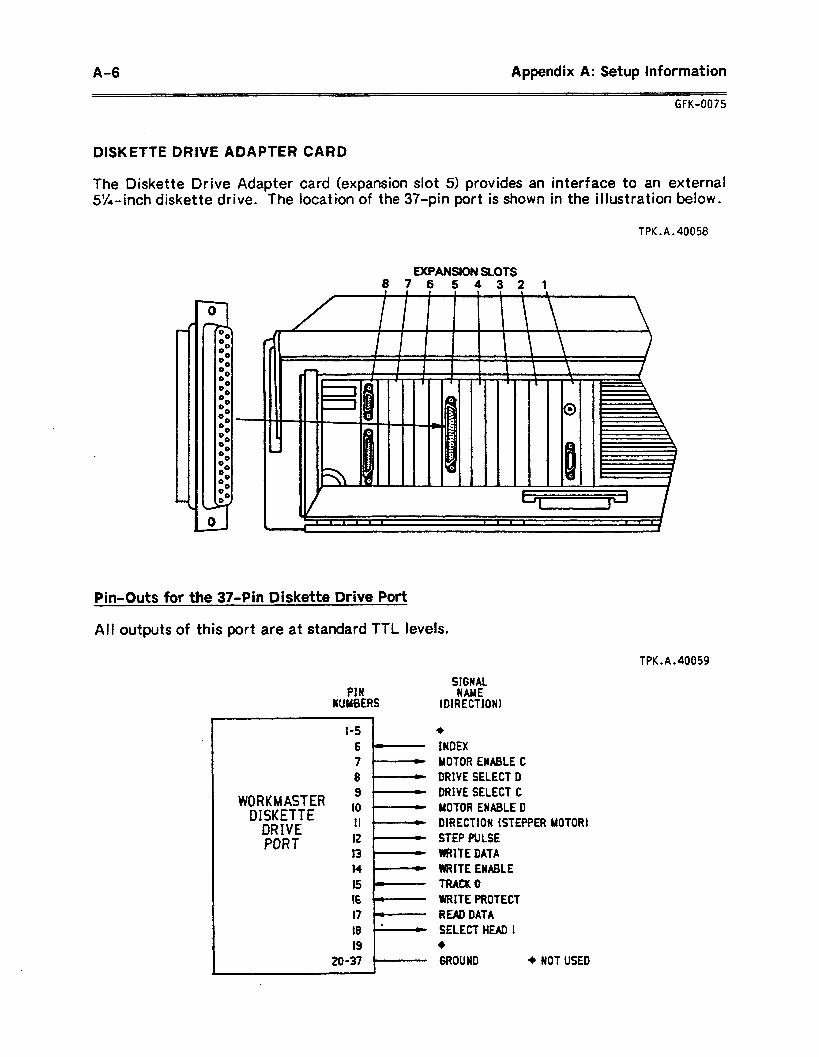
A-6 Appendix A: Setup Information
GFK-0075
DISKETTE DRIVE ADAPTER CARD
The Diskette Drive Adapter card (expansion slot 5) provides an interface to an external 5%~inch diskette drive. The location of the 37.pin port is shown in the illustration below.
TPK.A.40058
EXWWSIUN SLOTS 87654321
Pin-Outs for the 37.Pin Diskette Drive Port
All outputs of this port are at standard TTL levels.
TPK.A.40059
PIN WYBERS
WORKMASTER DISKETTE
DRIVE PORT
1-S
6
7
8 9
IO
11
12
13 I4 15 16 17 llr
I8 1.
19
20-37 1
SIGNAL NAME
HW?ECTIONl
+
INDEX MOTOR ENABLE C DRIVE SELECT D DRIVE SELECT C MOTOR ENABLE D DMECTION (STEPPER MOTOR) STEP PULSE WRITE DATA WRITE ENABLE TWX 0 WRITE PROTECT READ DATA SELECT HEAD 1 +
GROUND + NOT USED
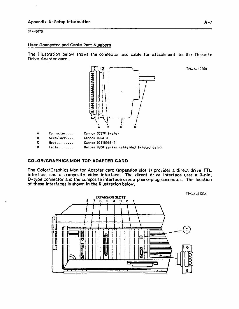
Appendix A: Setup Information A-7
GFK-0075
User Connector and Cable Part Numbers
The illustration below shows the connector and cable for attachment to the Diskette Drive Adapter card.
TPK.A.40060
Connector.. . . Screw1 ock.. . . Hood ,....... l
Cab1 e . . . . . . . .
Cannon DC37P (ma7 e) Cannon D20419
Cannon DC110963-4
Be’lden 9300 series (shielded twisted pai r)
COLOR/GRAPHICS MONITOR ADAPTER CARD
The Color/Graphics Monitor Adapter card (expansion slot 1) provides a direct drive TTL interface and a composite video interface. The direct drive interface uses a g-pin, D-type connector and the composite interface uses a phono-plug connector. The location of these interfaces is shown in the illustration below.
TPK.A.41234 EXPANSION SLOTS
S?654321
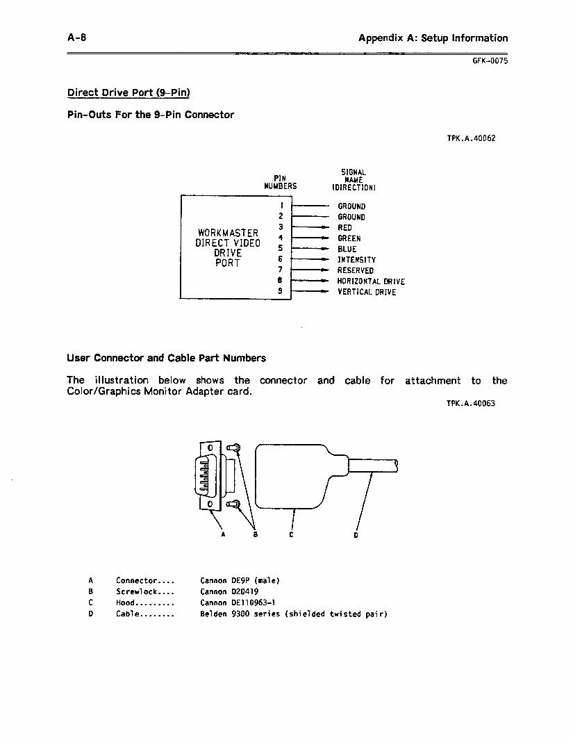
A-a Appendix A: Setup Information
GFK-0075
Direct Drive Port (9.Pin)
Pin-Outs For the g-Pin Connector
TPK.A.40062
PIN SIGNAL
NUMBERS NAME
1DIRECTIONI 7
I' GROUND 2' GROUND
WORKMASTER DIRECT VIDEO
DRIVE PORT
RED GREEN BLUE JNTENSITY RESERVED
I 8 HORIZONTAL DRIVE 9 VERTICALDRIVE
User Connector and Cable Part Numbers
The illustration below shows the connector and cable for attachment to the Color/Graphics Monitor Adapter card.
TPK.A.40063
A Connector.... Cannon DE9P (male) B Screwlock.. . . Cannon 020419
C Hood . . . . . . . . . Cannon DE1 10963-l 0 Cable . . . . . . . . Belden 9300 series (shielded twisted pai r)
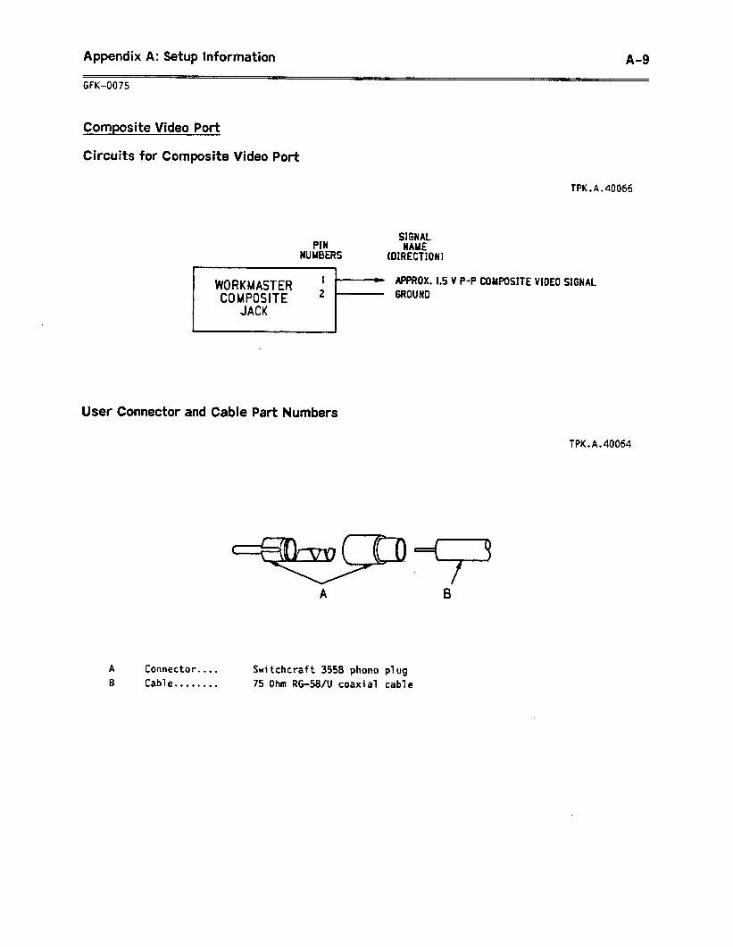
Appendix A: Setup Information A-9
GFK-0075
Composite Video Port
Circuits for Composite Video Port
TPK.A.40066
PIN WUYBERS
SIGNAL CSAUE
(DIRECTION)
APPROX.1.5 V P-P COMPOSITE VIDEO SIGNAL
User Connector and Cable Part Numbers
TPK.A.40064
A
B Connector....
Cable . . . . . . . . Switchcraft 3558 phono plug
75 Ohm R&58/U coaxial cable
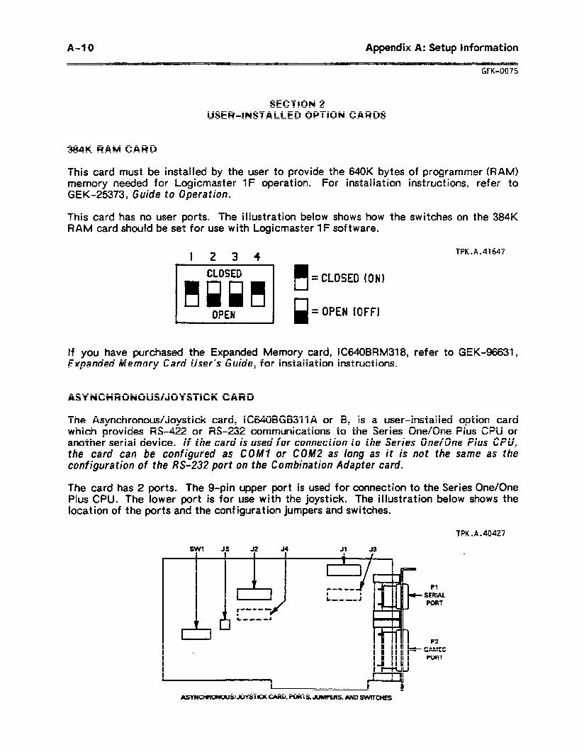
A-J 0 Appendix A: Setup Information
GFK-0075
SECTION 2 USER-INSTALLED OPTION CARDS
384K RAM CARD
This card must be installed by the user to provide the 640K bytes of programmer (RAM) memory needed for Logicmaster 1F operation. For installation instructions, refer to GEK-25373, Guide to Operation.
This card has no user ports. The illustration below shows how the switches on the 384K RAM card should be set for use with Logicmaster 1F software.
I 2 3 4
OPEN
TPK.A.41647
n =CLOSED ION) Id =OPEN (OFF1
If you have purchased the Expanded Memory card, IC640BRM318, refer to GEK-96631, Expanded Memory Card User’s Guide, for installation instructions.
ASYNCHRONOUS/JOYSTICK CARD
The Asynchronous/Joystick card, IC640BGB31lA or B, is a user-installed option card which provides W-422 or M-232 communications to the Series One/One Plus CPU or another serial device. If the card is used for connection to the Series One/One Plus CPU, the card can be configured as COW or COM2 as long as it is nut the same as the configuration of the RS-232 port on the Combination Adapter card.
The card has 2 ports. The g-pin upper port is used for connection to the Series One/One Pius CPU. The lower port is for use with the joystick. The illustration below shows the location of the ports and the configuration jumpers and switches.
TPK.A.40427
SW, 35 _ 52 34 Jl 33
P2 GAMES ?oRT
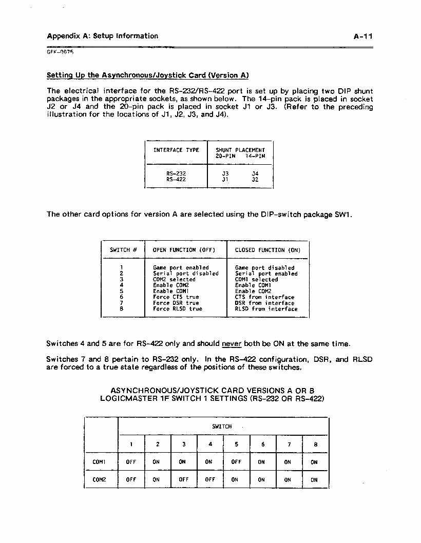
Appendix A: Setup information A-l 1
Setting Up the Asynchronous/Joystick Card (Version A)
The electrical interface for the RS-232/M-422 port is set up by placing two DIP shunt packages in the appropriate sockets, as shown below. The 14.pin pack is placed in socket J2 or J4 and the ZO-pin pack is placed in socket Jl or 33. (Refer to the preceding illustration for the locations of Jl, J2, J3, and J4).
INTERFACE TYPE
I
SHUNT PLACEMENT 200PIN M-PIN
I
RS-232 53 34 RS-422 31 32
The other card options for version A are selected using the DIP-switch package SWl.
SWITCH # OPEN FUNCTION (OFF) CLOSED FUNCTION (ON)
1 Game port enabled 2 Seri al port di sabl ed 3 COM2 se1 ected 4 Enable COM2 5 Enable COMI 6 Force CTS true 7 Force DSR true 8 Force RLSD true
Game port disabled Serial port enabled COMl se1 ected Enable COMl Enable COM2 CTS from interface OSR from interface RLSD from interface
Switches 4 and 5 are for M-422 only and should never both be ON at the same time.
Switches 7 and 8 pertain to RS-232 only. In the M-422 configuration, DSR, and RLSD are forced to a true state regardless of the positions of these switches.
ASYNCHRONOUS/JOYSTICK CARD VERSIONS A OR B LOGICMASTER 1F SWITCH 1 SETTINGS (RS-232 OR RS-422)
I SWITCH
1 2 3 4 5 6 7 8
COtll OFF ON ON ON OFF ON ON ON .
COM2 OFF ON OFF OFF ON ON ON ON
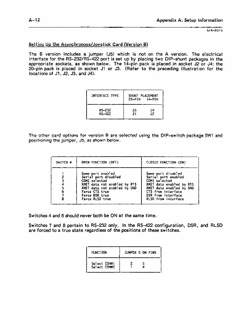
A-l 2 Appendix A: Setup Information
GFK-0075
Settins UP the Asvnchronous/Jovstick Card (Version 8)
The 8 version includes a jumper (J5) which is not on the A version. The electrical interface for the RS-232/R%422 port is set up by placing two DIP-shunt packages in the appropriate sockets, as shown below. The 14-pin pack is placed in socket 32 or J4; the 20.pin pack is placed in socket Jl or J3. (Refer to the preceding illustration for the locations of Jl , J2, J3, and 54).
INTERFACE TYPE SHUNT PLACEMENT 200PIN 140PIN
RS-232 33 34 RS-422 31 32
The other card options for version B are selected using the DIP-switch package SW1 and positioning the jumper, J5, as shown below.
SWITCH # OPEN FUNCTION (OFF) CLOSE0 FUNCTION (ON)
1 Game port enabled 2 Serial port di sabl ed 3 COM2 se1 ected 4 XMIT data not enabled by RTS 5 XMIT data not enabled by GND 6 Force CTS true 7 Force DSR true 8 Force RLSD true
Game port disabled Serial port enabled COMl se1 ected XMIT data enabled by RTS XMIT data enabled by GND CTS from interface DSR from interface RLSD from interface
Switches 4 and 5 should never both be ON at the same time.
Switches 7 and 8 pertain to RS-232 only. in the RS-422 configuration, DSR, and RLSD are forced to a true state regardless of the positions of these switches.
FUNCTION JUMPER 5 ON PINS
Se1 ect COMMl 2 3 Select COMMZ 1 4
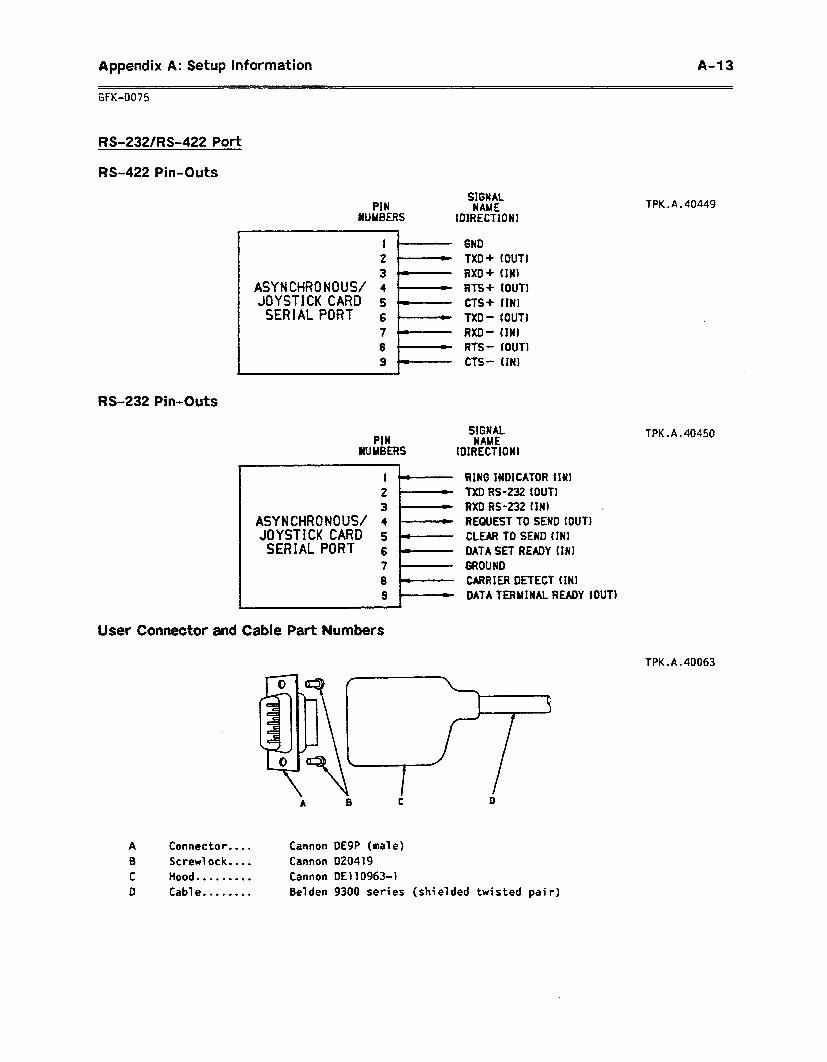
Appendix A: Setup Information A-l3
GFK-0075
RS-232/M-422 Port
RS-422 Pin-Outs
RS-232 Pin-Outs
User Connector and
SIGNAL MN NAME
NUMBERS fDIRECTiON1 TPK.A.40449
I I
2 - 3 4.
ASYNCHRONOUS/ 4 JOYSTICK CARD 5 SERIALPORT 6 _
7P- 8 I- 9 *
PIN
6ND TXD+ (OUT! RXD+ fINI RTS + (OUT) CTS+ IIN TXD - lOUTI RXD- fIN1 RTS- fOUT) CTS- fINI
SIGNAL NAME
NUMBERS fD1RECTIONI
I J- 2 - 3-
ASYNCHRONOUS/ 4 '1 JOYSTICK CARD s SERIALPORT 6
7 ” 8 9
Cable Part Numbers
RING lWDlCATOR fiNI TXD RS-232 IOUT) RXD RS-232 fINI . REQUEST TO SEND (OUT1 CLEAR TO SEND (tN1 DATA SET READY fINI GROUND CARRIER DETECT ffN1 DATA TERMINAL READY (OUT1
TPK.A.40450
TPK.A.40063
Connector.. . . Screwlock....
Hood . . . . . . . . . Cab1 e . . . . . . . .
Cannon DE9P (ma7 e)
Cannon 020419
Cannon DE1109634
Belden 9300 series (shielded twisted pai r)
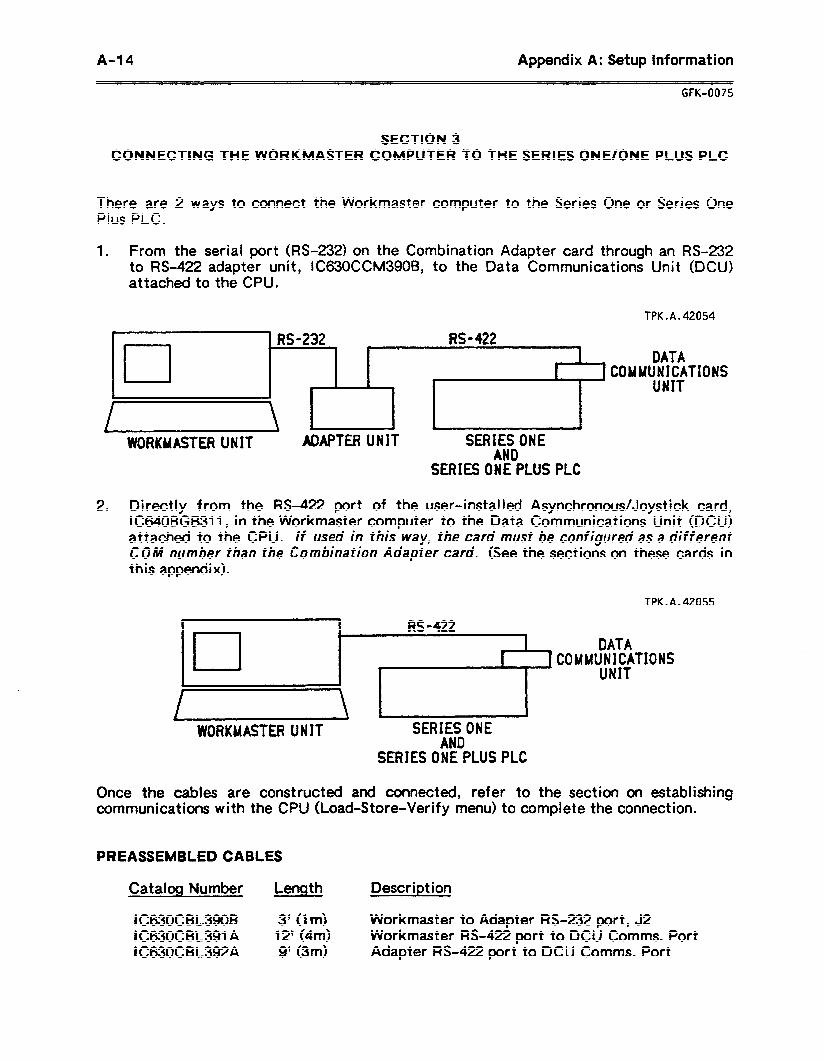
A-14 Appendix A: Setup information
GFK-0075
SECTION 3 CONNECTING THE WORKMASTER COMPUTER TO THE SERIES ONE/ONE PLUS PLC
There are 2 ways to connect the Workmaster computer to the Series One or Series One Plus PLC.
1 . From the serial port (RS-232) on the Combination Adapter card through an RS-232 to RS-422 adapter unit, IC630CCM390B, to the Data Communications Unit (DCU) attached to the CPU.
TPK.A.42054
cl RS-422
l
WORKUASTER UNIT ADAPTER UNIT SERIESONE AND
DATA UUNICATIONS
UNIT
SERIES ONE PLUS PLC
2 . Directly f ram the M-422 port of the user-installed Asynchronous/Joystick card, IC64OBGB311, in the Workmaster computer to the Data Communications Unit (DCU) attached to the CPU. If used in this way, the card must be configured as a different CO/U number than the Combination Adapter card. (See the sections on these cards in this appendix).
TPK.A.42055
9
cl
RS-422 I DATA
1 COMMUNICATIONS UNIT
WORKMASTER UNIT SERIES ONE AND
SERIESONEPLUS PLC
Once the cables are constructed and connected, refer to the section on establishing communications with the CPU (Load-Store-Verify menu) to complete the connection.
PREASSEMBLED CABLES
Catalog Number Length
IC630CBL39OB 3” 0mz IC630CBL391 A 129 (4m) lC630CBL392A 9’ (3m)
Description
Workmaster to Adapter M-232 port, J2 Workmaster RS-422 port to DCU Comms. Port Adapter RS-422 port to DCU Comms. Port
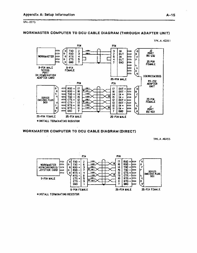
Appendix A: Setup Information A-15
_ GFK-0075
WORKMASTER COMPUTER TO DCU CABLE DIAGRAM (THROUGH ADAPTER UNIT)
TPK.A.42051
PIN PIN
0 TXD 2 -
2 ’ 3
0 RX0 3 - 0 RTS 4
0 CTS 5 0 GND 7
c
I J2 PORT
RS-232
25 PIN FEMALE
\LJ IC63OCCu3900
I E IWORKYASTER+
I I= 9-PIN YALE
SERIAL PORT
ON COWNATION ADAPTER CARD
g-PIN FEMALE E
1
N YALE
1 RS-232 ADAPTER
UNIT PIN PIN
I7 t6 I.4 15 I2 13 IO II 7
\ 0
0 ? 3
3
3 0
9
/ 0
0 C
r
t C
0
<
17 I6 I4 15 I2 13 IO II 7
RXD + - RXD - c TXD + = T)(D - f CTS + - CTS -
RTS + RTS - GND
OUT + OUT - IN + IN - OUT+ = OUT- = IN+ =
-IN- = GND =
SERIES OYUONE PLUS
DaJ 25 PIN
FEUALE
JI PORT
RS-422
25PIN FEMALE 25PIN MALE &PIN MALE
*INSTALL TERMINATING RESISTOR
WORKMASTER COMPUTER TO DCU CABLE DIAGRAM (DIRECT)
TPK.A.40455
/ol TXD+l 2 0 0
I TXD - 6 RX0 +
I 3
0 RXD - 7
<PIN PIN -
17 16 14 15 12 13
WORKMASTER ASYNCHRONOUS/ JOYSTICK CARD
/o 0
C r
t C 0
RXD + RXD - TX0 + TXD - CfS + = CTS - - RTS + - RTS -+ WD -
. N UALE
SERIES ONEAINEPLUS
DCU g-PIN MALE
25PIN FEMALE g-PIN FEMALE
WNSTALL TERMINATING RESISTOR
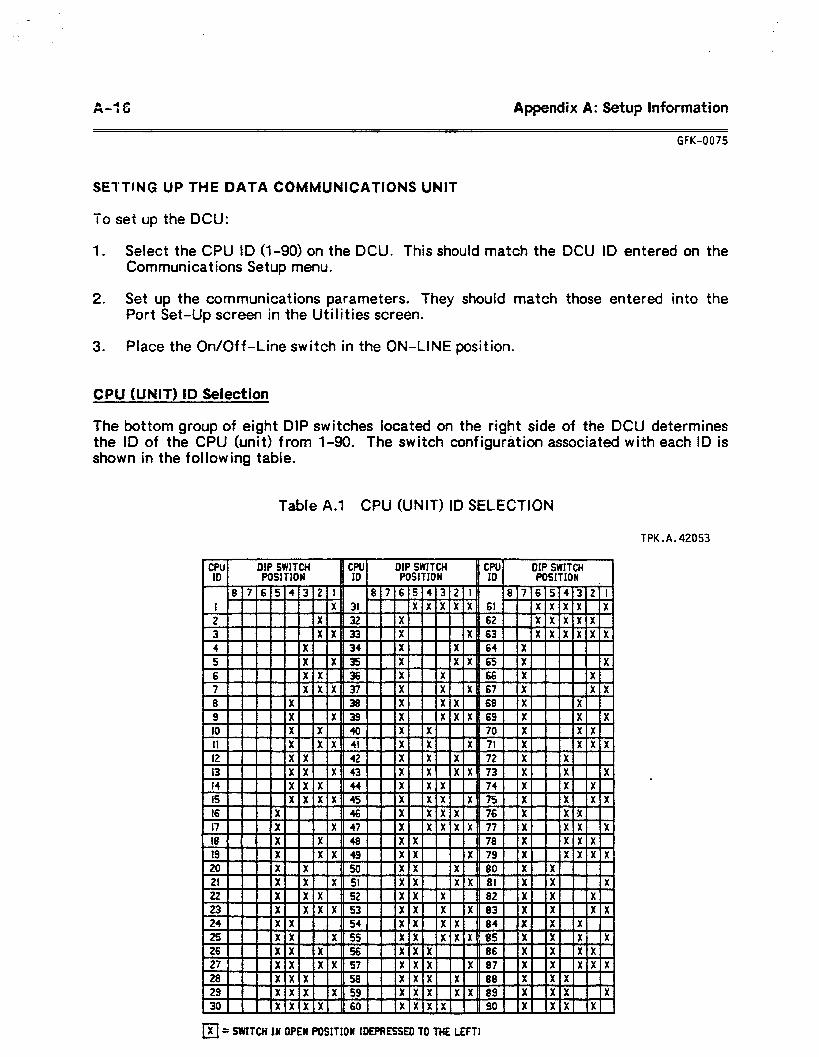
4 A-r 6 Appendix A: Setup Information
GFK-0075
SEWWIG UP THE DATA COMMUNICATIONS UNIT
To set up the DCU:
1 . Select the CPU ID (l-90) on the DCU. This should match the DCU ID entered on the Communications Setup menu.
2. Set up the communications parameters. They should match those entered into the Port Set-Up screen in the Utilities screen.
3 . Place the On/Off-Line switch in the ON-LINE position.
CPU (UNIT) ID Selection
The bottom group of eight DIP switches located on the right side of the DCU determines the ID of the CPU (unit) from l-90. The switch configuration associated with each ID is shown in the following table.
Table A.1 CPU (UNIT) ID SELECTION
TPK.A.42053
CPU ID
DIP SWITCH f CPU PoStffON ID
DIP SWITCH WSITlON
CPU' DIP SWITCH ID QOSITION
4 3 XX w X
X X
7 - 6 x X
-
4 X X X 5 -
T ,, .I” m.
i
XIX x x
* x x
0 X = SWITCH IN OPEU QOSITION 1DEPRESSED TO THE LEFT)
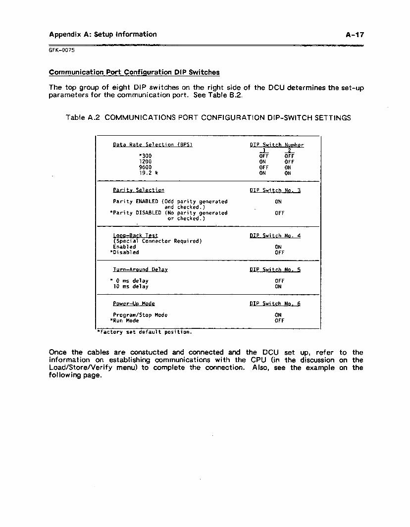
Appendix A: Setup information A47
GFK-0075
Communication Port Configuration DIP Switches
The top group of eight DIP switches on the right side of the DCU determines the set-up parameters for the communication port. See Table B.2.
Table A.2 COMMUNICATIONS PORT CONFIGURATION DIP-SWITCH SETTINGS
bta Rate Selection (BPS)
*300 1200 9600 19.2 k
PIP Switch Number 1
OFF 2 OFF
ON OFF OFF ON ON ON
Paritv Selection
Parity ENABLED (Odd parity generated and checked.)
*Parity DISABLED (No parity generated or checked.)
* ,
boo-Back Tect (Special Connector Required) Enabled
*Disabled
PIP Switch No. 3
ON
OFF
DIP Switch No. 4
ON OFF
Jurn-Around Del av
* 0 ms delay 10 ms delay
power-lh Mode
Program/Stop Mode *Run Mode
*Factory set default position.
PIP Switch No. 5
OFF ON
PIP Swi tch No. 6
ON OFF
Once the cables are constucted and connected and the DCU set up, refer information on establishing communications with the CPU (in the discussion Load/Store/Verify menu) to complete the connection. Also, see the example fol lowing page.
to the on the on the
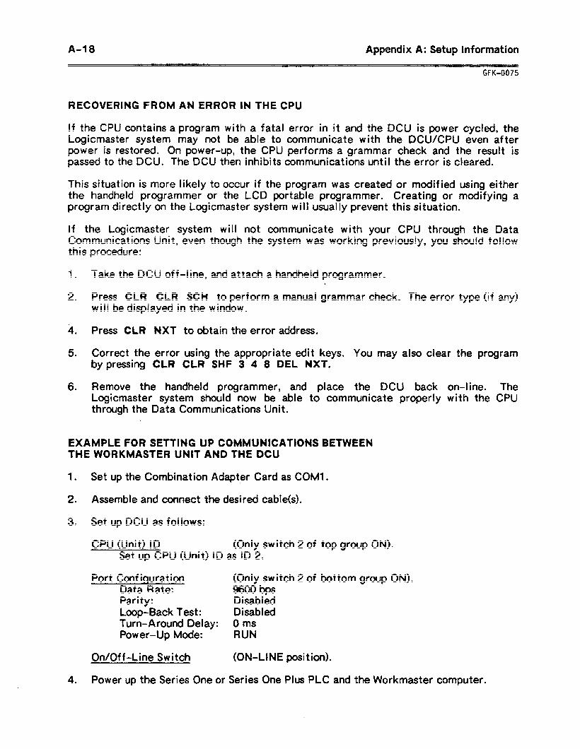
A-18 Appendix A: Setup Information
GFK-0075
RECOVERING FROM AN ERROR IN THE CPU
ff the CPU contains a program with a fatal error in it and the DCU is power cycled, the Logicmaster system may not be able to communicate with the DCUKPU even after power is restored. On power-up, the CPU performs a grammar check and the result is passed to the DCU. The DCU then inhibits communications until the error is cleared.
This situation is more likely to occur if the program was created or modified using either the handheld programmer or the LCD portable programmer. Creating or modifying a program directly on the Logicmaster system will usually prevent this situation.
If the Logicmaster system will not communicate with your CPU through the Data Communications Unit, even though the system was working previously, you should follow this procedure:
1 .
2 .
Take the DCU off-line, and attach a handheld programmer.
Press CLR CLR SCH to perform a manual grammar check. The error type (if any) will bedisplayed in the window.
. 4 .
5 .
Press CLR NXT to obtain the error address.
Correct the error using the appropriate edit keys. You may also clear the program by pressing CLR CLR SHF 3 4 8 DEL NXT.
6 . Remove the handheld programmer, and place the DCU back on-line. The Logicmaster system should now be able to communicate properly with the CPU through the Data Communications Unit.
EXAMPLE FOR SETTING UP COMMUNICATIONS BETWEEN THE WORKMASTER UNIT AND THE DCU
1 . Set up the Combination Adapter Card as COMl l . .
2 . Assemble and connect the desired cable(s).
3. Set up DCU as follows:
CPU (Unit) ID (Only switch 2 of top group ON). Set up CPU (Unit) ID as ID 2.
Port Configuration (Only switch 2 of bottom group ON). Data Rate: 9600 bps Parity: Disabled Loop-Back Test: Disabled Turn-Around Delay: 0 ms Power-Up Mode: RUN
On/Off-Line Switch (ON-LINE posit ion).
4 . Power up the Series One or Series One Plus PLC and the Workmaster computer.
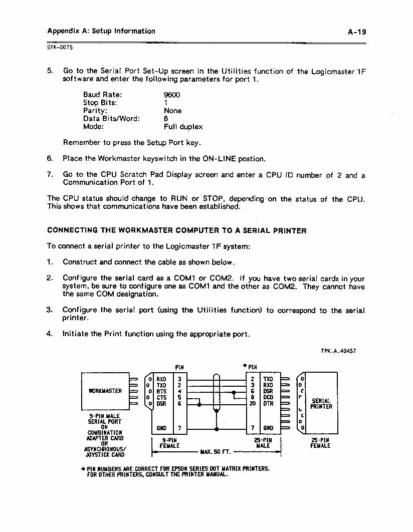
Appendix A: Setup Information A-19
GFK-0075
5 . Go to the Serial Port Set-Up screen in the Utilities function of the Logicmaster 1F software and enter the following parameters for port 1.
Baud Rate: 9600 Stop Bits: 1 Parity: None Data Bits/Word: 8 Mode: Full duplex
Remember to press the Setup Port key.
6 .
7 .
Place the Workmaster keyswitch in the ON-LINE postion.
Go to the CPU Scratch Pad Display screen and enter a CPU ID number of 2 and a Communication Port of 1.
The CPU status should change to RUN or STOP, depending on the status of the CPU. This shows that communications have been established.
CONNECTING THE WORKMASTER COMPUTER TO A SERIAL PRINTER
To connect a serial printer to the Logicmaster 1F system:
1 . Construct and connect the cable as shown below.
2. Configure the serial card as a COW or COM2. If you have two serial cards in your system, be sure to configure one as COMl and the other as COM2. They cannot have the same COM designation.
3. Configure the serial port (using the Utilities function) to correspond to the serial printer.
4. Initiate the Print function using the appropriate port.
WRKYASTER 0 TX0 0 RTS
I 0 CTS ODSR
‘I 6WD
+ PIN
9-PIN MALE SERIAL PORT
ON COMBINATION
ADAPTER CARD OR
ASYNCHRONOUS/ JDYSTICU CARD
TX0 = RX0
DCD DTR
6WD -
/ 0
0 C
P
t c
0 0
\
SERIAL PRINTER
TPK.A.40457
2%PIN FEMALE
+ PIN NUUBERS ARE CORRECT FOR EPSON SERIES DOT MATRIX PRINTERS. FOR OTHER PRINTERS, CONSULT THE PRINTER MANUAL.
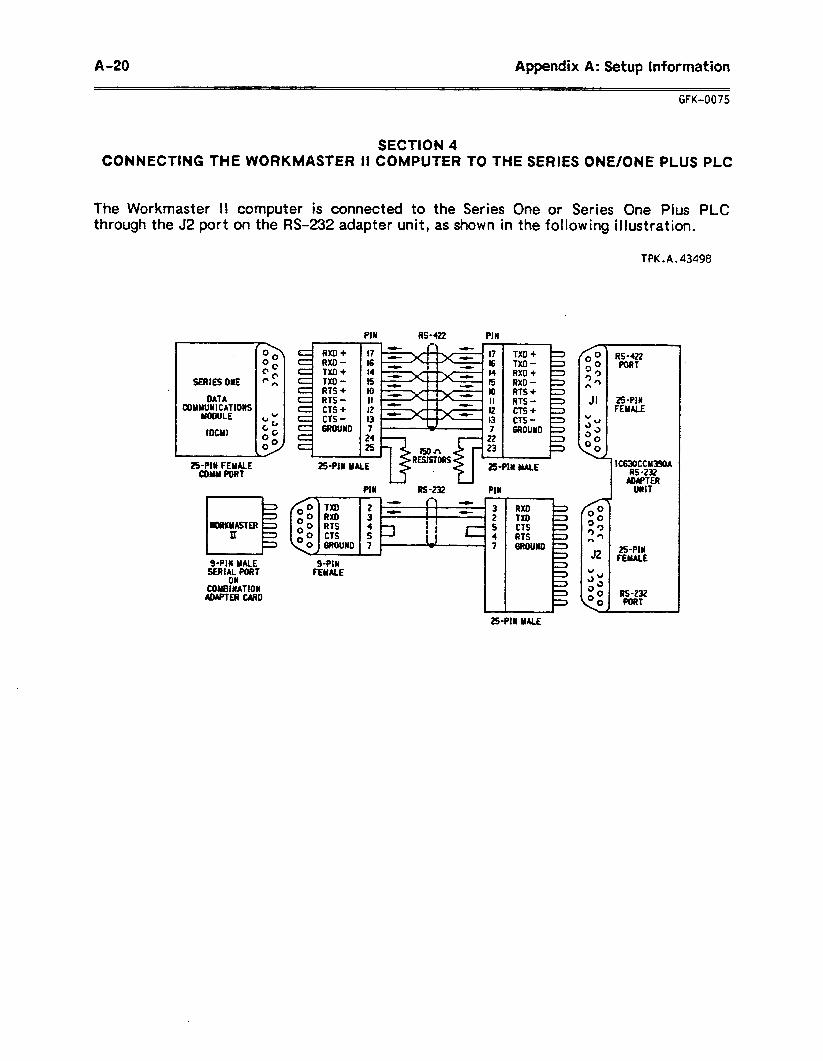
A-20 Appendix A: Setup Information
GFK-0075
SECTION 4 CONNECTING THE WORKMASTER II COMPUTER TO THE SERIES ONE/ONE PLUS PLC
The Workmaster II computer is connected to the Series One or Series One Plus PLC through the J2 port on the RS-232 adapter unit, as shown in the following illustration.
TPK.A.43498
SERIES ONE
DATA COM~UNIN~~IONS
IDCMI
C RXD+ RXD - TXD + TXD - RTS + RTS -
c cTs+
T PIN
17 I6
I: lo II I2 r3 7
25PIN MALE
it 16
I: 10 II 12 13 7
PIN
9-PtN FEMME
TXD + TX0 - RXD + RXD - RTS + RTS -
::c 6ROUND
- 3 2 5 4 7
RXD TXD CTS RTS BROUND
25PIN FEMALE
25P1N FEMME
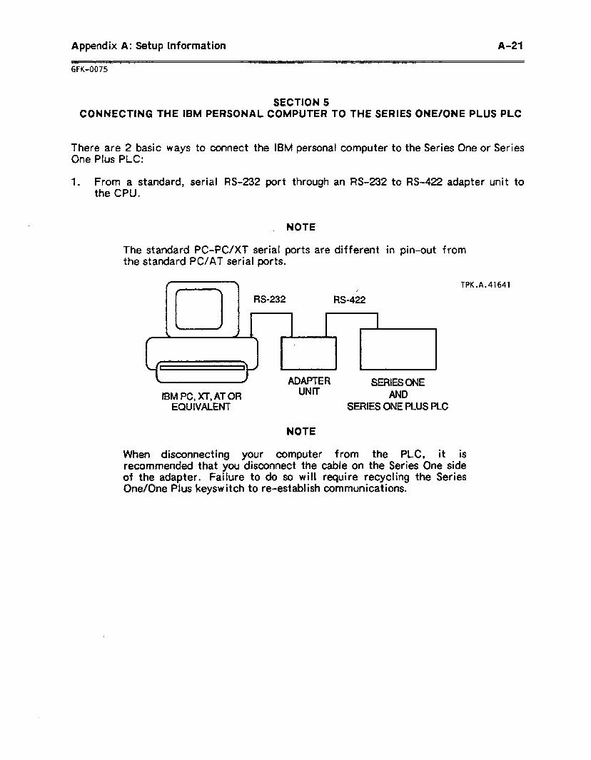
Appendix A: Setup Information A-21
GFK-0075
SECTION 5 CONNECTING THE IBM PERSONAL COMPUTER TO THE SERIES ONE/ONE PLUS PLC
There are 2 basic ways to connect the IBM personal computer to the Series One or Series
One Plus PLC:
1 . From a standard, serial RS-232 port through an M-232 to M-422 adapter unit to the CPU.
NOTE
The standard PC-PC/XT serial ports are different in pin-out from the standard PC/AT serial ports.
IBM PC, XT, AT OR EQUIVALENT
ADAPTER SERIES ONE UNIT AND
SERIES ONE PLUS PLC
TPK.A.41641
When disconnecting your computer’ from the PLC, it is recommended that you disconnect the cable on the Series One side of the adapter. Failure to do so will require recycling the Series One/One Plus keysw itch to re-establish communications.
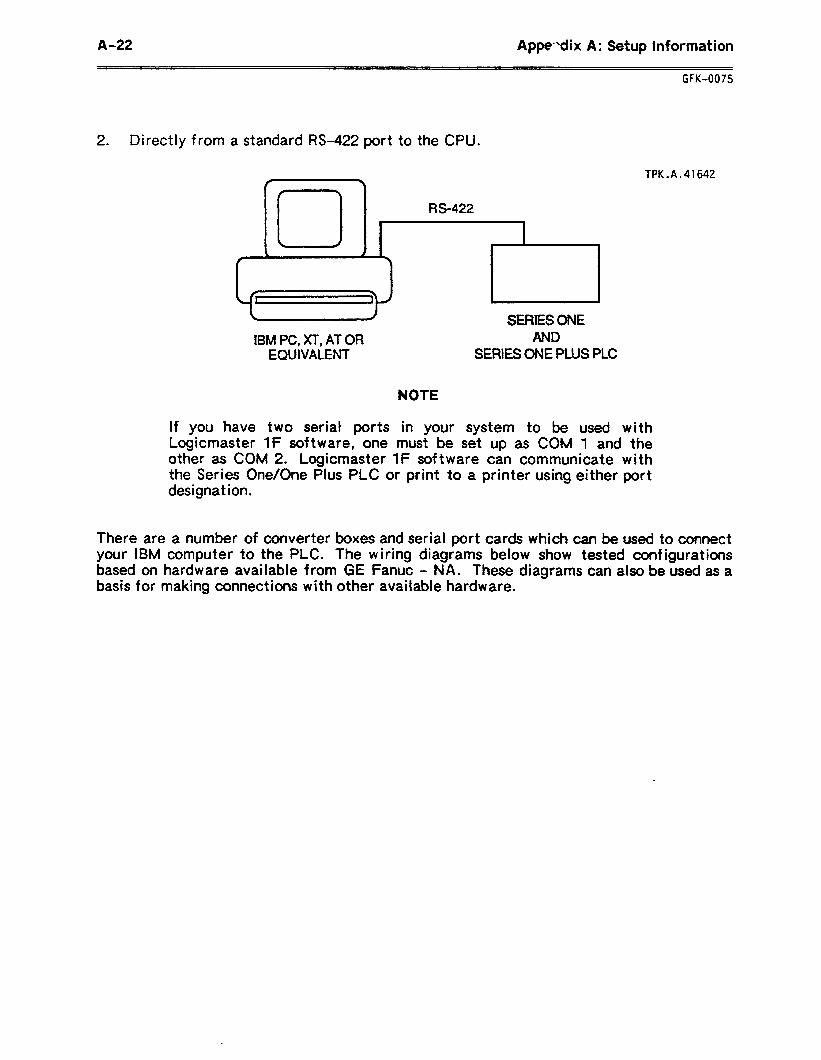
A-22 Appendix A: Setup Information
GFK-0075
2 l Directly from a standard IX-422 port to the CPU.
TPK.A.41642
RS-422
IBM PC, XT-, AT OR EQUIVALENT
SERIES ONE AND
SERIES ONE PLUS PLC
NOTE
If you have two serial ports in your system to be used with Logicmaster IF software, one must be set up as COM 1 and the other as COM 2. Logicmaster 1F software can communicate with the Series One/One Plus PLC or print to a printer using either port designat ion.
There are a number of converter boxes and serial port cards which can be used to connect your IBM computer to the PLC. The wiring diagrams below show tested configurations based on hardware available from GE Fanuc - NA. These diagrams can also be used as a basis for making connections with other available hardware.
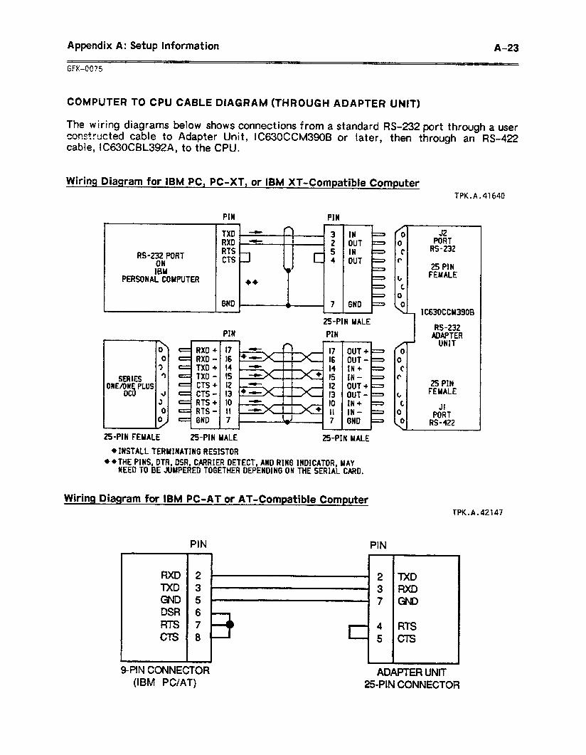
Appendix A: Setup Information A-23
COMPUTER TO CPU CABLE DIAGRAM (THROUGH ADAPTER UNIT)
The wiring diagrams below shows connections from a standard RS-232 port through a user pons+wcted cable to Adapter Unit, IC630CCM390B or later, then through an B-422 cabI& IC630CBL392A, to the CPU.
Wiring Diagram for IBM PC, PC-XT, or IBM XT-Compatible Computer TPK.A.41640
RS-232 PORT ON IBM
PERSONAL COUPUTER
PIN PIN 4 \
TX0 - l I w ’ 3 RX0 i - ! I 8 I 4 2 RTS CTS -zI
S
Li c 4
++
SERIES OWE/ONE PLUS
OCII
25PtN FEMALE
IN OUT IN OUT
PIN
25PIN MALE
PIN
2%PIN MALE
OUT+ 2 OUT-g SN + IN- = OUT+b OUT- = IN+ = IN- b GND =
.
( MALE
4 INSTALL TERMINATING RESISTOR **THE PINS, DTR, DSR, CARRIER DETECT, AND RING INDICATOR, MAY
NEED TO BE JUMPERED TOGETHER DEPENDING ON THE SERIAL CARD.
Wiring Diagram for IBM PC-AT or AT-Compatible Computer
PIN PIN
DSR RTS CTS
4 RTS 5 C-E
32 PORT
RS-232
25 PSN FEMALE
1 I C630CCM3900
RS-232 ADAPTER
UNIT
r I 25 PIN t I FEMALE
fPK.A.42147
9-PIN CONNECTOR ADAPTER UNIT (IBM PC/AT) 2SPIN CONNECTOR
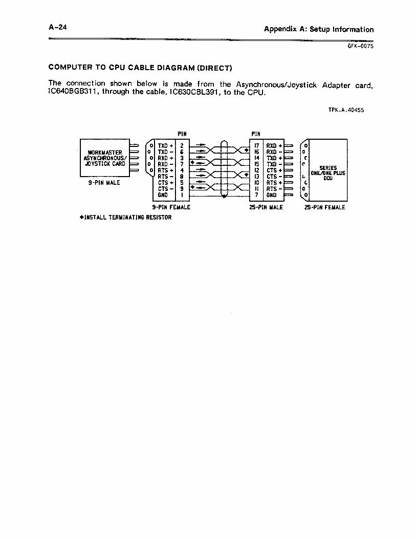
A-24 Appendix A: Setup Information
COMPUTER TO CPU CABLE DIAGRAM (DIRECT)
The connection shown below is made from the IC640BGB311 9 through the cable, lC630CBL391, to
AsynchronousIJoyst ick Adapter card, the CPU.
ASYNCHRONOUS/ JOYSTICK CARD
g-PIN MALE
TXD + TXD - RXD + RXD - RTS + RTS - CTS + CTS - GND
PIN PIN
GFK-0075
2 17 6 t6 3 I4 7 I5 4 12 8 13 5 IO 9 II
. RXD + - RXD - - TXD + = TXD - - CTS + - CTS - = RTS + -
g-PIN FEMALE 25PIN MALE
0 T- 0 c
TPK.A.40455
SERIES EmE PLUS
DCU
L 2%PIN FEMALE
L
+INSTALL TERMINATING RESISTOR
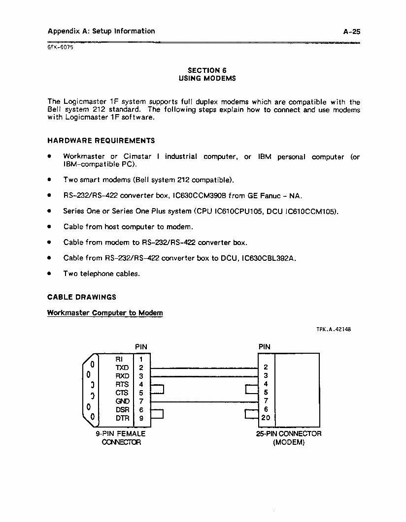
Appendix A: Setup Information A-25
GFK-0075
SECTION 6 USING MODEMS
The Logicmaster 1F system supports full duplex modems which are compatible with the Bell system 212 standard. The following steps explain how to connect and use modems with Logicmaster 1F software.
HARDWARE REQUIREMENTS
l Workmaster or Cimstar 1 industrial computer, or IBM personal computer (or IBM-compatible PC).
a Two smart modems (Bell system 212 compatible).
0 RS-232/i%-422 converter box, 1C630CCl~l39OB from GE Fanuc - NA.
0 Series One or Series One Plus system (CPU IC61OCPU105, DCU IC61OCCM105).
a Cable from host computer to modem.
0 Cable from modem to RS-232/F&422 converter box.
0 Cable from RS-232/R%422 converter box to DCU, iC630CBL392A.
l Two telephone cables.
CABLE DRAWINGS
Workmaster Computer to Modem
RI TXD RXD RTS CTS
TPK.A.42148
PIN PIN
6 9
g-PIN FEMALE -Ta
25PIN CONNECTOR (MODEM)
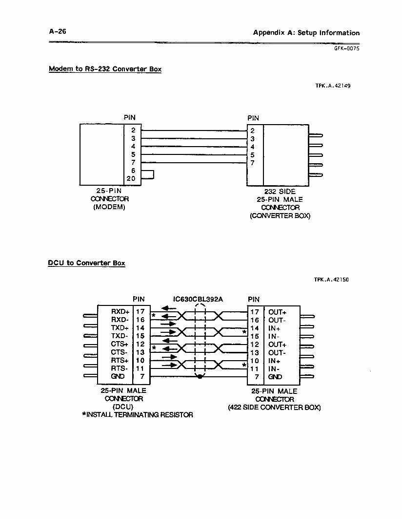
A-26 Appendix A: Setup Information
~~~ GFK-0075
Modem to M-232 Converter Box
TPK.A.42149
PIN PIN
. 250PIN
coNNE%ToR (MODEM)
2 3 4 5 7 6
20
25PIN MALE CONWZTOR
(CONVERTER BOX)
DCU to Converter Box
TPK.A.42150
PIN lC63OCBL392A PIN
RXD+
RXD- # 1 TXD+ t ’ TXD- t : CTS+
c : CTS- RTS+
t ’ RTS- t 1
25PIN hr
(DCU “INSTALL TERh
17 16 14 15 12 13 10 11
17 16 14 15 12 13 10 11
- OUT+ OUT- IN+ IN OUT + OUT- IN+ IN a&
I== f=
ALE ‘OR I INATING RESISTOR
25PIN MALE
(422 SIDE CONVERTER BOX)
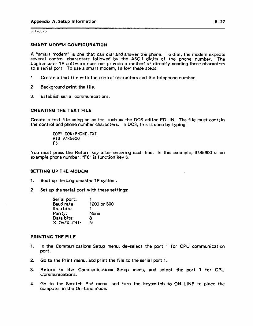
Appendix A: Setup Information A-27
GFK-0075
SMART MODEM CONFIGURATION
A “smart modem” is one that can dial and answer the phone. To dial, the modem expects several control characters followed by the ASCII digits of the phone number. The Logicmaster 1F software does not provide a method of directly sending these characters to a serial port. To use a smart modem, follow these steps:
1 . Create a text file with the control characters and the telephone number.
2 . Background print the file.
3 . Establish serial communications.
CREATING THE TEXT FILE
Create a text file using an editor, such as the DOS editor EDLIN. The file must contain the control and phone number characters. in DOS, this is done by typing:
COPY CON:PHONE.TXT ATD 9785600 F6
You must press the Return key after entering each line. In this example, 9785600 is an example phone number; ‘*F6” is function key 6.
SETTING UP THE MODEM
1 . Boot up the Logicmaster 1F system.
2. Set up the serial port with these settings:
Serial port: 1 Baud rate: 12000r300 Stop bits: 1 Parity: None Data bits: 8 X-On/X-Off : N
PRINTING THE FILE
1 . In the Communications Setup menu, de-select the port 1 for CPU communication port.
2 . Go to the Print menu, and print the file to the serial port 1.
3 . Return to the Communications Setup menu, and select the port 1 for CPU Communications.
4 . Go to the Scratch Pad menu, and turn the keyswitch to ON-LINE to place the computer in the On-Line mode.
A-28 Appendix A: Setup Information
GFK-0075
SECTION 7 MULTIDROP CONFIGURATION
The Logicmaster 1 F system supports multidrop configuration up to eight CPUs and eight DCUs. The following functions are provided in the multidrop configuration.
e Poll CPUIDCU. 0 Start/Stop CPU. a Load/Store/Verify operation with any CPU in the network. 0 Monitor the I/O, Register table. 0 On-l ine changes. 0 Password operation.
HARDWARE REQUIREMENTS
l Workmaster or Cimstar I industrial computer, IBM personal computer, or IBM-compatible computer (but not a Workmaster II computer).
l RS-422 serial port adapter (Game port card). l 8 Series One or Series One Plus PLC systems. l Cable from Workmaster to multiple CPUs.
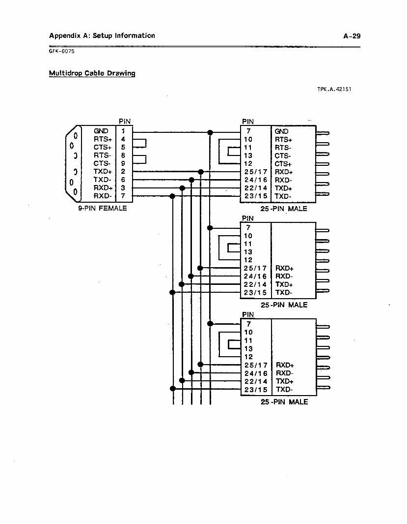
Appendix A: Setup Information A-29
GFK-0075
Multidrop Cable Drawing
RTS+ CTS+ RTS- CTS- TXD+ TXD- RXD+ RXD-
PIN PIN
1
g-PIN FEMALE
10 11 13 12 25117 24116 RXD- 22114 TXD+ 23115 TXD-
TPK.A.42151
25/l 7 24/l 6 22/l 4 23/l 5
IL
250PIN MALE
RXD+ RXD- TXD+ TXD-
25 -PIN MALE
4’
25 -PIN MALE

Appendix B: Glossary of Terms B-l
GFK-0075
APPENDIX B GLOSSARY OF TERMS
Address: A specific memory location.
AND (Logical): A mathematical operation between bits. All bits must be 1 for the result to be 1.
AND (Function): An operation that places two contacts or groups of contacts in series.
Constants: A predetermined value stored in a register. This value does not change.
Counter: A circuit internal to the PLC, which can be programmed to control other devices according to a preset number of on/off transitions.
Annotation: Explanatory text in a program. Annotation includes names, nicknames, rung explanations, and coil labels.
CPU: Central Processing Unit. The central device or controller that interprets user instruct ions, makes decisions, and executes the functions based on a stored program. This program specifies actions to be taken to all possible inputs.
ASCII: American Standard Code for lnformat ion Interchange. An eight-bit (7 bits plus 1 parity bit) code used for data.
Background: Some computer functions, such as background printing, can be performed in the “background” while other functions are being used.
CPU Version: The CPU contains operating instructions, called *‘f ifmwarefT. The version of the firmware in the CPU determines which program functions the CPU can perform.
Cross-Reference Table: A table that keeps track of program references.
Backup: A duplicate version of a program, Directory: A file which contains the created prior to editing the program. names and specifications of other files.
Baud: A unit of data tramsmission. Baud rate is the number of bits per second transmitted.
Discrete: Refers to the inputs and outputs in the system. The term lldiscrete” includes both real and internal l/O.
BCD: Binary Coded Decimal. A 4-bit system in which individual decimal digits (0 through 9) are represented by 4-bit binary numerals. For example, the number 43 is represented by OlOO(4) 001 l(3) in the BCD notation.
Disk: A hard disk or floppy diskette, used as an information storage and retrieval device.
DOS: Disk Operating System. A group of utility programs which provide the structure for system operations.
Bit: Binary Digit. This represents the smallest unit of data storage in memory. The value of a bit can be either 1 or 0.
Byte: A group of 8 consecutive bits operated on as a single unit.
Double Left Rail: The graphic representation of an area of ladder logic, the execution of which is under the control of an MCR function.
Byte Boundary: The bit which marks the beginning of a new 8-bit byte. For example, 1,9,17, etc.
Drive: A floppy-diskette drive or hard disk drive. The identification of the drive, such as Drive A.
B-2 Appendix 8: Glossary of Terms
Firmware: A series of software instructions contained in ROM (Read Only Memory). These instruct ions control internal operations.
I/O: Input/Output. That portion of the PLC to which field devices are connected. isolates the CPU from electrical noise.
Full Duplex: A method of data transmission. In full-duplex transmission, data may be sent and received in both direct ions, simultaneously.
l/O Scan: The CPU’s monitoring of all inputs and all outputs within a prescribed time.
Internal Reference: A program reference that does not represent a hardware device.
Function Key: A key (Fl-F8) whose function is controlled by software. This function which may change within the program. The Logicmaster 1 F software displays the current assignments of the function keys at the bottom of the screen.
INV (Logical Invert): A mathematical operation on bits in a matrix. All ones are replaced by zeros, and all zeros are replaced by ones. The results are placed in another matrix.
Group: A series of 8 consecutive K: An abbreviation for kilo or exactly references, such as I/O points or internal 1024 in the world of computers. Usually coi Is. related to 1024 words of memory.
Half-Duplex: A method of data transmission. In half-duplex transmission, data can only be sent in one direction at a time.
ladder Diagram: A graphic representation of decisional logic.
Hardware: Ail of the mechanical, electrical, and electronic devices in the PLC system and its application.
Line of Logic: A rung of ladder logic may contain up to 7 lines of logic in parallel. IX single line may contain up to 8 elements in series.
Help Screens: Instructive text screens, displayed by pressing the Help (FlO) key.
Load: The function used to transfer programs to the Logicmaster system’s RAM memory.
Input Devices: Devices that mechanically or electrically supply data to the PLC. Typical input devices are limit switches, pushbut tons, pressure switches, digital encoders, and analog devices.
Logic: A fixed set of responses (outputs) to various external conditions (inputs). Also referred to as the program.
Inputs: A signal, typically ON or OFF, that provides information to the PLC.
Master Software: The original Logicmaster 1 F software diskettes shipped from the factory.
Instruction: A word, wsually an acronym, or group of words and numerals that are part of a program entered into user memofy.
Memory: A physical place to store information, such as programs and/or data.
Memory Size: The number of registers of memory in the CPU.
Instruction Set: A group of program functions available in the Series One or Series One Pius CPU.
Millisecond (msec): One thousandth of a second (0.001 second).
GFK-0075
Appendix B: Glossary of Terms B-3
GFK-0075
Mnemonic: An abbreviation or other representat ion of a program instruct ion. The mnemonic appears in the ladder diagram where the function is used.
Mode Select Switch: The keyswitch on the front of the Workmaster computer that selects the mode of the Logicmaster 1F system. When using another type of computer, mode is selected in the software.
Monitor Mode: A mode of operation that allows the operating program to be monitored. No program changes can be made in Monitor mode.
OR (Logical): A mathematical operation between bits, whereby if any bit is a 1, the result will be a 1.
OR (Function): An operation that places two contacts or groups of contacts in parallel. Either controls the resultant status.
Off-Line Mode: A mode of operation used for program entry and editing, before the program is transferred to the CPU. This mode can be used for program development in a location remote from the CPU.
On-Line Changes: Changes to I/O or register references, and certain other changes, made when the Logicmaster 1F system is on-line to an operating CPU, and the programs in both are exactly the same.
On-Line Mode: A mode of operation that al lows observation of an operating program. Certain changes may be made to the program while it is operating.
Output: A signal, typically ON or OFF, originating from the PLC with user-supplied power that controls external devices based upon commands from the CPU.
Override: To remove control of an relay reference from its normal source. For instance, overridden relay inputs ignore information from input devices such as
l pushbuttons or limit switches.
Parity: A type of integrity check on data.
Peripheral Equipment: External. units that can communicate with a PLC.
PLC: A commonly-used abbreviation for Programmable Logic Cont rot ler.
Power Flow: In a ladder diagram, the symbolic flow of power represents the logical execution of pfogfam functions. For each function, it is important to know what happens when power is received, and under what conditions power flow is output.
Preset: A numerical value entered into a register which establishes a limit for counters or timers. A coil will energize when the stored value is reached.
Program: A sequence of functions and/or instructions entered into a programmable logic controller to be executed by the CPU for the purpose of controlling a machine or process.
Programmer: A device for entry, examination, and alteration of the PLC*s memory, including logic and storage areas.
Rail: The symbolic connection between ladder rungs. The left rail represents the positive power source.
RAM: Random Access Memory. In this manual, the term RAM is used to refer to the volatile memory of the computer. This memory stores the Logicmaster software, program files, and related data while power is applied to the system.
Read: To have data entered into a PLC from a peripheral unit.
Reference: An I/O or register address that supplies status or data to an instruction in a program.
Reference Tables: A group of formatted tables which can display the values of I/O and registers in the system.
B-4 Appendix B: Glossary of Terms
Register: A group of 16 consecutive bits Table: A group of consecutive storage in register memory. Each register is locat ions in memory. The beginning numbered, beginning at 0001. Register address and length of the table are memory is used for temporary storage of specified in the program. Data may be numerica! values, and for bit manipulation. accessed randomly in a table.
Retentive Output: An output that will remain on in its last state, even if power is removed.
Teach Mode: A function used to create customized key assignments for the Fl to F8 keys.
Rung: A unit of ladder logic. One rung may have up to 7 parallel lines of logic connected to the left rail, but these must combine so that there is just one connection to the right rail.
Thumbwheel Switch: A rotating numeric switch used to input numeric data to a PLC.
Scan: The CPU’s repeated execution of all program logic, I/O service, peripheral service, and self-testing. This occurs automatically, many times each second.
Timer: An internal function that can be used to control the operating cycle of other devices by a preset and accumulated time interval.
Scratch Pad: A memory storage area in the PLC, which stores the characteristics of the CPU. A similar function in the Logicmaster 1 F software is also called the Scratch Pad.
Verify: A function used to compare progtam content. The program in system RAM memory may be compared with a program f tom the CPU or from a disk drive.
View Mode: A playback display of the key functions defined in Teach mode.
Side File: A secondary ladder logic file, consisting of part of a ladder logic program. This file can be added to another program.
Status Line: The line at the top of the screen that shows the status of the CPU, the Logicmaster 1F mode, and other information.
Watch Dog Timer: A built-in timer which shuts down the CPU if the scan takes too long .
Word: A group of 16 consecutive bits in the Input or Output tables.
Store: The function used to transfer programs from the Logicmaster system’s RAM memory to the CPU or to disk.
Work Area: The data-entry display in the lower right corner of the screen. The work area has three lines: the text (top) line, the reference (center) line, and the value (bottom) I ine.
Supervisor Menu: The main menu in Logicmaster 1F software. It lists all the principal system functions, and the function keys that control those functions.
Write: To output or transfer data from the PLC to a peripheral unit.
GFK-0075
Appendix C: Keyboard Translator Chart c-1
GFK-0075
APPENDIX C KEYBOARD TRANSLATOR CHART
This appendix contains a keyboard translator chart to use with the IBM-PC, PC-XT, PC-AT, or IBM-compatible personal computer. The chart has been printed in triplicate to provide you with extra copies. The sheet has al so been formatted so that you can remove each copy of the chart from the manual for easier reference.
c-2 Appendix C: Keyboard Translator Chart
GFK-0075
THIS PAGE INTENTIONALLY LEFT BLANK.

Appendix C: Keyboard Translator Chart c-3
GFK-0075
TPK.A.42152

C-4 Appendix C: Keyboard Translator Chart
~~ UK-0075
Appendix 0: Software Function Key Flow Diagrams D-l
GFK-0075
APPENDIX 0 SOFTWARE FUNCTION KEY FLOW DIAGRAMS
The following diagrams illustrate the relationships between the software function keys. Position of functions within the diagram does not always represent actual key sequence.
Key
1 .
2 .
3 .
4 .
5 .
6 .
7 .
function availability depends on the following conditions:
Avai lable soft ware opt ions.
Scratch Pad content.
Cursor position.
Program logic at the cursor position.
Logicmaster 1F operating mode (computer keyswitch position).
CPU Memory Protect keysw i tch position.
instruction set selection.
If a key function does not display, check the list above.
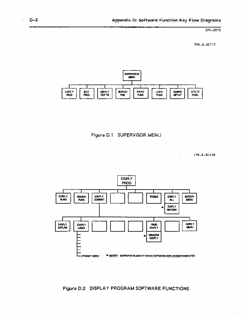
. D-2 Appendix D: Software Function Key Flow Diagrams -_ ~
GFK-0075
TPK.A.42117
Figure 0.1 SUPERVISOR MENU
TPK.A.42118
I I
I I I b \ \ , \ I , I 1
DISPLY DSPLY DISRY cuumwT *
I * DISPLY I I NICUNM
Figure 0.2 DISPLAY PROGRAM SOFTWARE FUNCTIONS
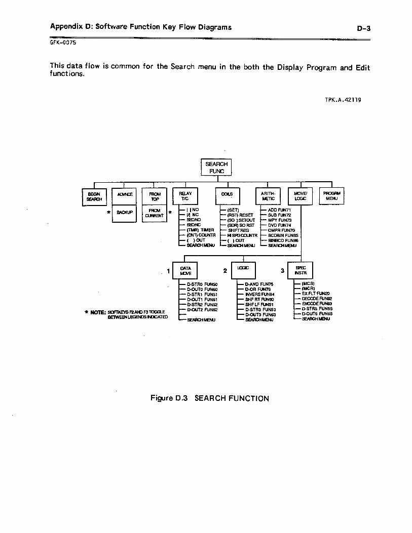
Appendix D: Software Function Key Flow Diagrams
r,FK-0975
D-3
This data flow is common for the Search menu in the both the Display Program and Edit functions.
fPK.A.42119
.
* NOTE:
I I . . DATA
3 MWE 2 - 3 sf6c NSTFI . * \ ,
- DSTRO FUNS0 - D-AND FlJN7S - WCS) - DCWTO FUN60 - D-OR FUN76 - WR)
7 D-STRl FUNS1 - INVERS FUN84 - EX FLT FUN20 - D-OUT1 FUN61 - SHF RT FUNBO -DECQDEFUN82 -D=STR2 FUNS2 - SHF LF FUN81 -ENCCDERJN83
sommsF2AmF3TmaE - DUJT2 FUN62 - D-STR3 FUNS3 - D-STRS FUNSS
BEIWEW~NICATED - o-OUT3 FUN63 - DXWTS FUN65 SMRCHMEJW -SmRcHMEw -sEARaIm
Figure D.3 SEARCH FUNCTION
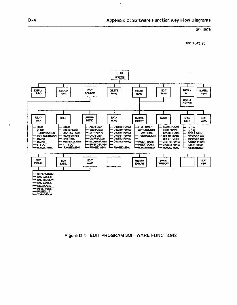
D-4 Appendix D: Software Function Key Flow Diagrams
GFK-0075
TPK.A.42120
SUPER!?
c MENU
I I I I , 1
I I . REIAY ARITH- (#TA TMwcu EDIT
+ \I MENU 4 / 1 . 4 I
-lINO - (SET) - ADD FUN71 - D-SfRO FUNS0 -(TM) TIMER -BAND RIIWS
-VI NC - (FM=) RESET -slJBFuN72 - o-OUT0 RJ?wo -(cNT)camTR -D-OR FUN76 (MC9
--SHUNT/OPEN - (SO ) SETOUT - MPY FUN73 e- BSTRt FUNS1 -TWWH TIMER
- (MCR) - WVERS FUN84 - B RT fum
-vERTcm&mPEN -(SOR)SORST -0VDfuN74 -tXU1FLN61 -Tl=iWlim -SHFRTFUN6Q wan SglNo - SHFTREG -CMPR FUN70 -PSTR2 FUN52 - -SHFLFFUIW - ~AJNB~ SBCINC - i+IS!‘Dm - BCDBIN FUN65 - m12 FUN62 I--W - D-STR3 FUNS3 - O_flRS WNSS
( )WT -( )m - BINBCO FUN86 - -D-CUT3 FUN63 - D-OUT FUN= WNGEDMENU -RwGQ&mlJ -wNGmnmu -RwGEDwMJ -Rm=Dmw -m4GQhmu
.
UPPERlLWER UNDCIDELC UND W/DEL W UND UDEL L DELKx/Kx. RESEBELECT PASTECUT ToPBoTTcw
Figure 0.4 EDIT PROGRAM SOFTWARE FUNCTIONS
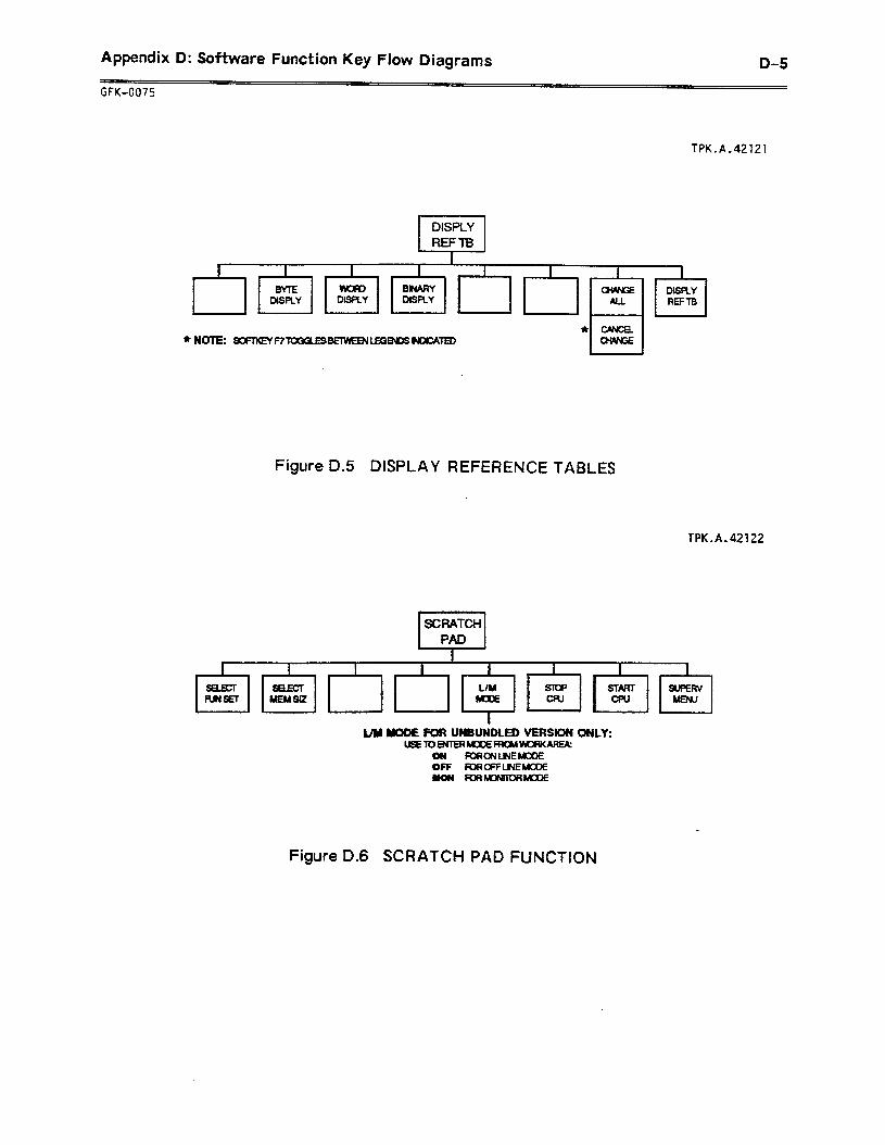
Appendix D: Software Function Key Flow Diagrams
CFK-0075
D-5
TPK.A.42121
* *NNOTE: XFMEY~~~OGOL~S- LEGBssNDcAED
DISPLY REF TB
Figure D.5 DISPLAY REFERENCE TABLES
TPK.A.42122
. I . I , I ,\ I I ,~ 1 I . * 1 .
L/M START FUNSET MEM SQ MENU
l 4 . . 4
I Oy YODE FOR UNBUNDLED VERSION ONLY:
UsEm~~FRoMwoRKAREIA: ow FUWNLNEMOOE Off KXNFFLJNEMOOE MON m~mclllooE
Figure D.6 SCRATCH PAD FUNCTION
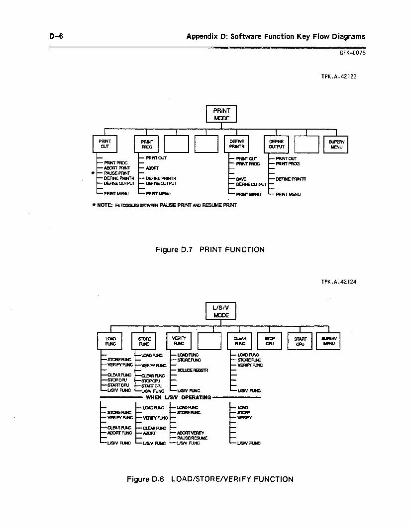
D-6 Appendix 0: Software Function Key Flow Diagrams
UK-0075
fPK.A.42123
I I
I I I I I \‘ I I DEF?dE
ENU t . . l
PRNTan PRNTPRm
DEF NE PRNTR DEFNE PRNTf3
tr: PRMOUT PRMmoG
t I- DEFREPRINTR
DEFNEanPur EFNEourPur
PRIM= MENU IE PRNTMENU
* NOTE: H~~~ESBETWEBI PAUSE PRINT AhD REWhdE PRJM
Figure D.7 PRINT FUNCTION
TPK.A.42124
WHEN L/S/V OPERATING
Figure 0.8 LOAD/STORE/VERIFY FUNCTION
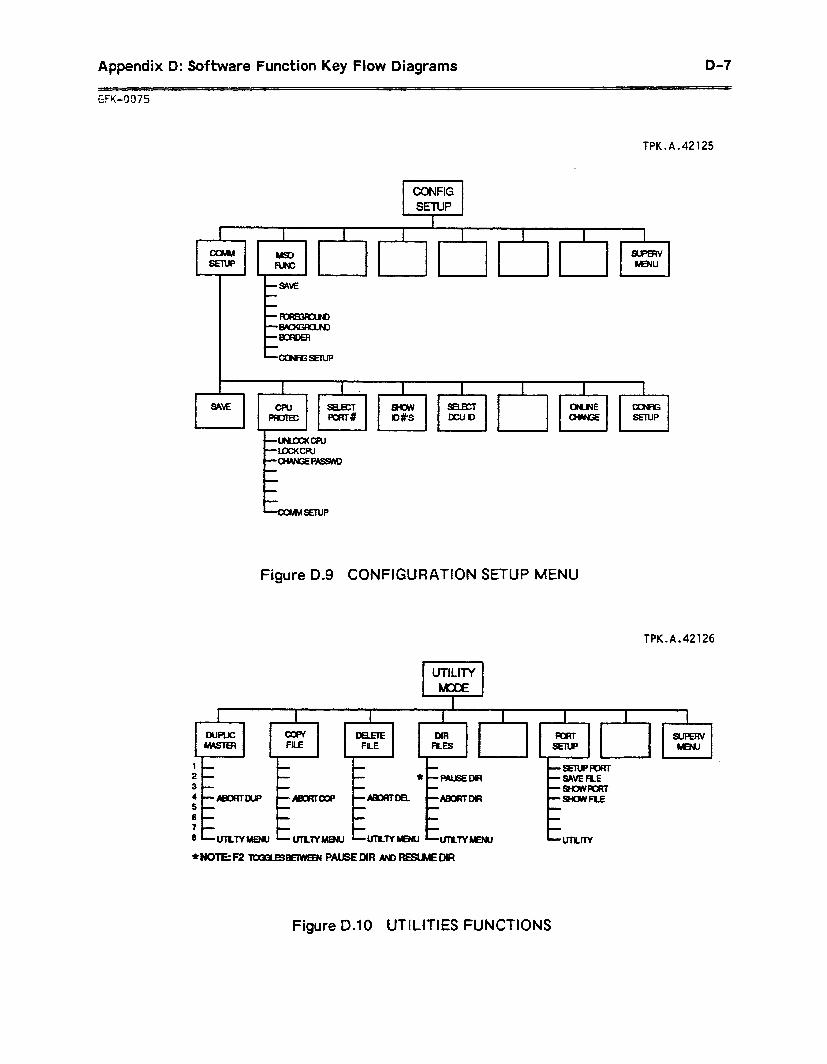
Appendix Q: Software Function Key Flow Diagrams o-7
TPK.A.42125
Figure D.9 CONFIGURATION SETUP MENU
TPK.A.42126
I \ I ) I I
DwLlc DIR FILE FJLE FLES
I . L I- - -
_’ ‘LItI
P- - - * -mu6EDlR 3- - - - 4 ABORTWP -ma? -Ammoa ABomDfR 5 6 - 7 - - 6 un=fYMENu -unlYMmu UnLlY~ -lmL7wmu hmLl7Y
*NOTES -emwmu PA&E DIR AND RESWEDIR
Figure D.10 UTILITIES FUNCTIONS

Appendix E: Logicmaster 1 Software Package E-l
~ -~- GFK-0075
APPENDIX E LOGICMASTER ONE SOFTWARE PACKAGE
The Logicmaster 1 Programming and Documentation package provides off-line programming and documentation for the Series One CPU (IC61OCPUlOl A, IC610CPU1016, and lC61OCPUlOlC). In general, the functions provided in this package operate the same as the Logicmaster 1F functions. This appendix describes the differences between the Logicmaster 1 F and Logicmaster 1 software. Where the requirements are the same for these two packages, no mention will be made and reference should be made to the appropriate section(s) of this manual. Help text is also available.
Once installed and/or set up properly, according to chapter 2 of this manual, the Logicmaster Programming software will operate in one of two ways:
1 . At the DOS prompt, enter LlWM to start the software for operation on the Workmaster or Cimstar I computer. The Logicmaster 1 software will recognize the Workmaster keyswitch.
2 . At the DOS prompt, enter LlPC to start the software for operation on a Workmaster II computer, an IBM-PC, PC-XT, or PC-AT computer, or on an IBM-compatible personal computer. Refer to section 6 of chapter 2 for alternate key sequences.
When installing Logicmaster 1 software on a hard disk, the Duplicate Master function automatically creates a subdirectory called Ll on the hard disk. You may wish to add this directory to a path statement. This will supply DOS with a path to the \Ll subdirectory f ram other directories. This is normally done by placing a path statement in the AUTOEXEC.BAT start-up file. For example: PATH \Ll.
DISPLAY PROGRAM
This function is not available in the Logicmaster 1 package.
REFERENCE TABLES
This function is not available in the Logicmaster 1 package.
The password function is not available in the Logicmaster 1 package.

E-2 Appendix E: Logicmaster 1 Software Package
GFK-0075
PROGF?AMMING
Chapter 12 presents general programming concepts and describes basic programming instructions. Refer to chapter 12 and the information provided here when programming the Series One PLC using Logicmaster 1 software.
The pages listed below provide a reference to the functions described in chapter 12.
Page
Normally Open Contact
Normally Closed Contact
Shunt/Open
Vertical/Open
Normally Open Sequencer
Normally Closed Sequencer
Master Control Start
Master Control’ Reset
out
Set
Reset .
12-22
Set Out 12-23
Set Out Reset 12-24
Timer 12-25
Thumbwheel Timer 12-26
Counter 12-27
Thumbwheel Counter 12-28
High Speed Counter 12-29
Shift Register 12-30
12-12
12-13
12-14
12-15
12-16
12-17
12-18
12-19
12-20
12-21
Refer to the table on the following pages for the valid references and ranges for these functions.
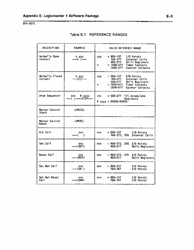
Appendix E: Logicmaster 1 Software Package E-3
GFK-0075
Table E.l REFERENCE RANGES
DESCRIPTION
Normally Open Contact
EXAMPLE VALID REFERENCE RANGE
XYY -- IT
YYY = 000-157 I/O Points 160-377 Internal Coils 4009577 Shift Registers
x = T600-677 Timer Contacts CdOO-677 Counter Contacts
Normally Closed Contact
XYY r/T
YYY = 000-157 I/O Points 160-377 Internal Coils 400-577 Shift Registers
X = T600-677 Timer Contacts C600-677 Counter Contacts
Drum Sequencer xxx K YYYY xxx = 600-677 T/C Accumulate -f ~--_-STEP- Registers
K YYYY = KOOOO-Kg999
Master Control -[MCS]- Start
Master Control Reset
-[MCR]-
Out Coil
Set Coil
Reset Coi 1
Set Out Coil
Set Out Reset Coil
xxx xxx = 000-157 I/O Points ( 1 160-373, 376 Internal Coils
xxx xxx = 000-373, 376 I/O Points -0( SET) 400-577 Shift Registers
xxx ’ xxx = 000-373, 376 I/O Points -(RST) 400-577 Shift Registers
xxx xxx = 000-157 I/O Points -(SO 1 700-767 I/O Points
xxx xxx = 000-157 I/O Points -(SOR) 700-767 I/O points
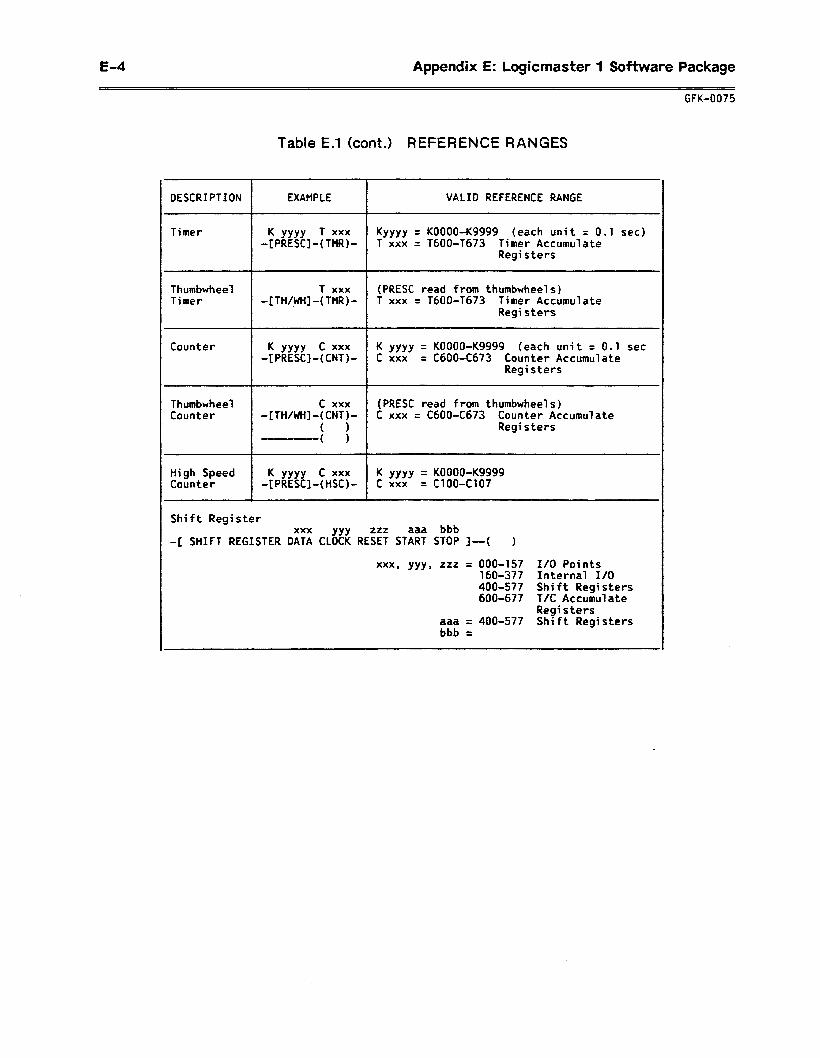
E-4 Appendix E: Logicmaster 1 Software Package
GFK-0075
Table E.l (cont.) REFERENCE RANGES
DESCRIPTION EXAMPLE VALID REFERENCE RANGE
Timer K YYYY T xxx KYYYY = KOOOO-Kg999 (each unit = 0.1 set) -[PRESC]-(TMR)- T xxx = T600-T673 Timer Accumulate
Registers
Thumbwheel T xxx (PRESC read from thumbwheels) Timer -[TH/WH]-( TMR)- T xxx = TdOO-T673 Timer Accumulate
Registers
Counter K YYYY c xxx K YYYY = KOOOO-Kg999 (each unit = 0.1 set -[PRESC]-(CNT)- C xxx = CdOO-C673 Counter Accumulate
Registers
Thumbwheel c xxx (PRESC read from thumbwheels) Counter -[TH/WH]-( CNT)- c xxx = CdOO-C673 Counter Accumulate
( 1 Registers ( )
High Speed K YYYY C xxx K YYYY = KOOOO-Kg999 Counter -[PRESC]-(HSC)- C xxx = C100-Cl07
Shift Register xxx YYY zzz aaa bbb
-[ SHIFT REGISTER DATA CLOCK RESET START STOP I-( )
xxx, yyy, zzz = 000-157 I/O Points 160-377 Internal I/O 400-577 Shift Registers 600-677 T/C Accumulate
Registers aaa = 400-577 Shift Registers bbb =
Appendix F: Logicmaster 1 Junior Software Package F-l
GFK-OQ75
APPENDIX F LOGICMASTER ONE JUNIOR SOFTWARE PACKAGE
The Logicmaster 1 Junior Programming and Documentation package provides off-line programming and documentation for the Series One Junior CPU (IC609SJRxx~). in general, the functions provided in this package operate the same as the Logicmaster 1 F functions. This appendix describes the differences between the Logicmaster 1F and Logicmaster 1 Junior software. Where the requirements are the same for these two packages, no mention will be made and reference should be made to the appropriate section(s) of this manual. Help text is also available.
__ -
Once installed and/or set up properly, according to chapter 2 of this manual, the Logicmaster Programming softwafe will operate in one of two ways:
1 . At the DOS prompt, enter LJRWM to start the software for operation on the Workmaster or Cimstar I computer. The Logicmaster 1 Junior software will recognize the Workmaster keyswitch.
2 . At the DOS prompt, enter LlPC to start the software for operation on a Workmaster Ii computer, an IBM-PC, PC-XT, or PC-AT computer, or on an IBM-compatible personal computer. Refer to section 6 of chapter 2 for alternate key sequences.
When installing Logicmaster 1 Junior software on a hard disk, the Duplicate Master function automatically creates a subdirectory called LJR on the hard disk. You may wish to add this directory to a path statement. This will supply DOS with d path to the \LJR subdirectory f ram other directories. This is normally done by placing a path statement in the AUTOEXEC.BAT start-up file. For example: PATH \LJR.
DISPLAY PROGRAM
This function is not available in the Logicmaster 1 Junior package.
This function is not available in the Logicmaster 1 Junior package.
COMMUNICATION SETUP
The password function is not available in the Logicmaster 1 Junior package.
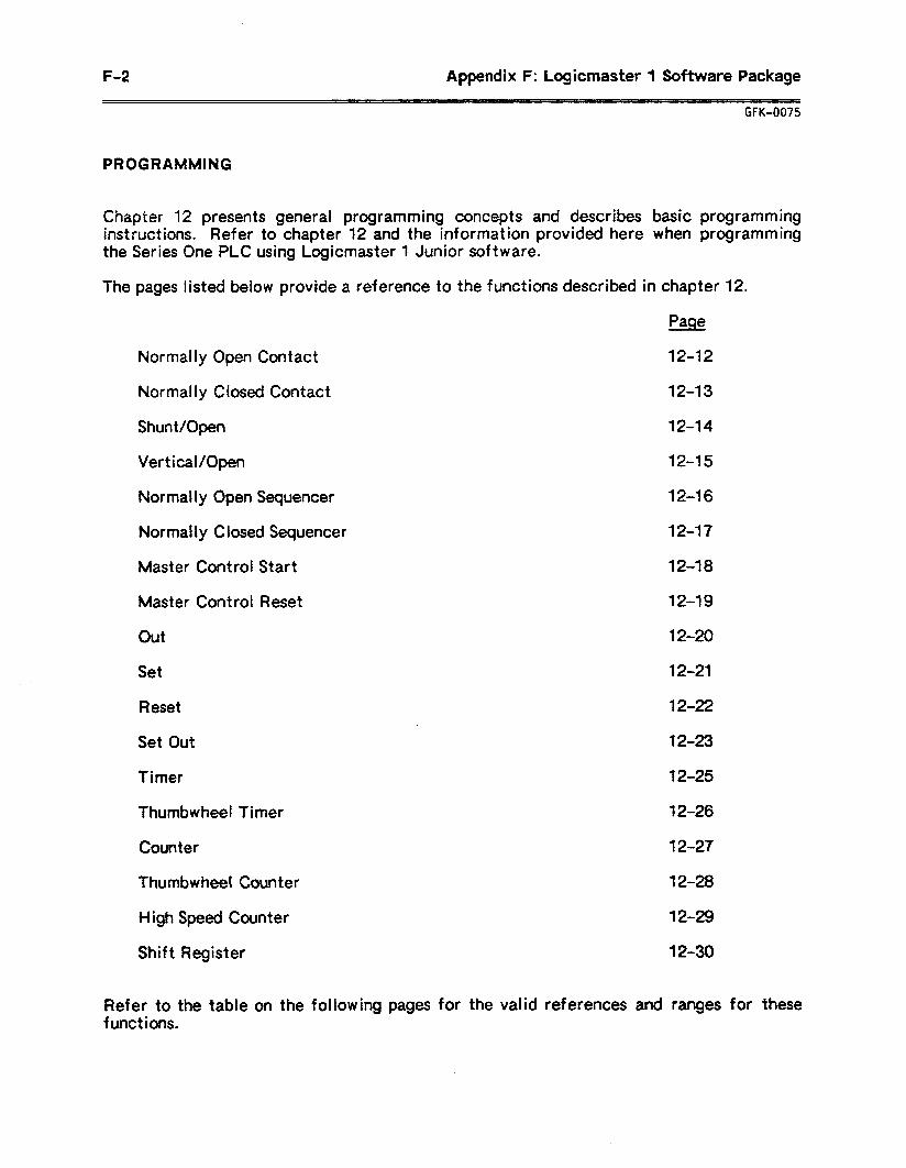
F-2 Appendix F: Logicmaster 1 Software Package
GFK-0075
PROGRAMMING
Chapter 12 presents general programming concepts and describes basic programming instructions. Refer to chapter 12 and the information provided here when programming the Series One PLC using Logicmaster 1 Junior software.
The pages listed below provide I
Normally Open Contact
Normally Closed Contact
Shunt/Open
Vertical/Open
Normally Open Sequencer
a reference to the functions described in chapter 12.
Page
12-12
12-13
12-14
12-15
12-16
Normally Closed Sequencer 12-17
Master Control Start 12-18
Master Control Reset 12-19
out 12-20
Set 12-21
Reset 12-22
Set Out 12-23
Timer 12-25
Thumbwheel Timer 12-26
Counter 12-27
Thumbwhee! Counter 12-28
High Speed Counter 12-29
Shift Register 12-30
Refer to the table on the following pages for the valid references and ranges for these functions.
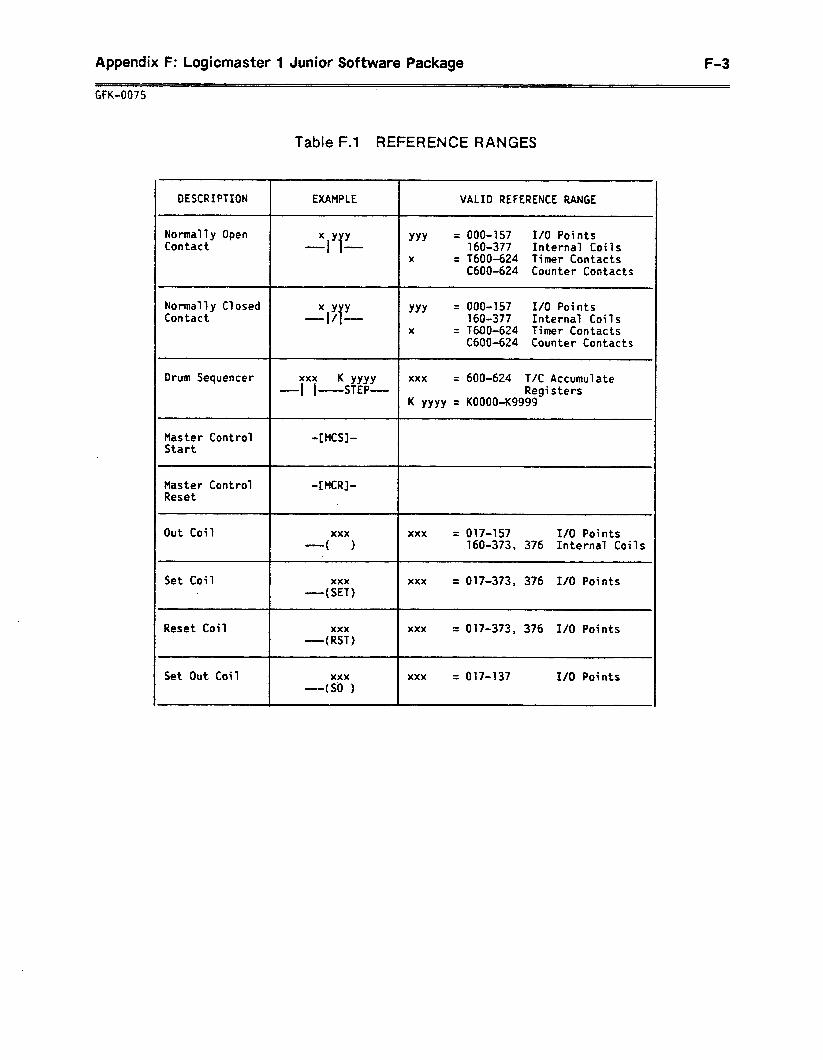
Appendix F: Logicmaster 1 Junior Software Package F-3
GFK-0075
Table F.l REFERENCE RANGES
oESCRIPTION
Normally Open Contact
EXAMPLE VALID REFERENCE RANGE
XYY IT
YYY = 000457 I/O Points 160-377 Internal Coils
X = f600-624 Timer Contacts C600-624 Counter Contacts
Normally Closed Contact
XYY YYY = 000-157 I/O Points
Iif 160-377 Internal Coils X = WOO-624 Timer Contacts
C600-624 Counter Contacts
Drum Sequencer
Master Control Start
xxx K YYYY xxx = 600-624 T/C Accumulate
I 1 -STEP- Registers K YYYY = KOOOO-Kg999
-[HCS]-
Master Control Reset
-[MCR]-
Out Coil
Set Coil .
Reset Coil
xxx ( )
xxx -(SET)
xxx -(RST)
xxx = 017457 I/O Points 160-373, 376 Internal Coils
xxx = 017-373, 376 I/O Points
xxx = 017-373, 376 I/O Points
Set Out Coil xxx -(SO )
xxx = 017-137 I/O Points
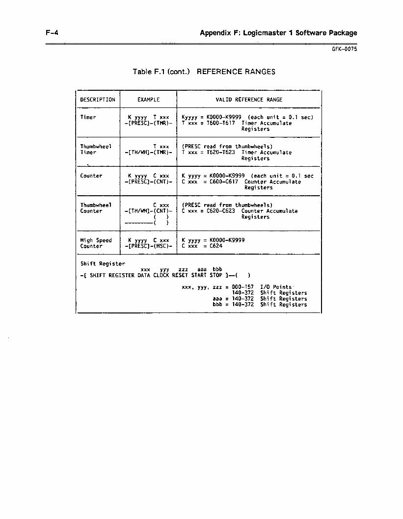
F-4 Appendix F: Logicmaster 1 Software Package
GFK-0075
Table F.1 (cont.) REFERENCE RANGES
DESCRIPTION EXAMPLE VALID REFERENCE RANGE
Timer K YYYY T xxx KYYYY = KOOOO-Kg999 (each unit = 0.1 set) -[PRESC]-(TMR)- T xxx = TdOO-T617 Timer Accumulate
Registers
Thumbwheel T xxx (PRESC read from thumbwheels) Timer -[TH/WH]-(TMR)- T xxx = T620-1623 Timer Accumulate
Registers *
Counter K YYYY c xxx K YYYY = KOOOO-Kg999 (each unit = 0.1 set -[PRESC]-(CNT)- c xxx = CdOO-C617 Counter Accumulate
Registers
Thumbwheel c xxx (PRESC read from thumbwheels) Counter -[fH/WH]-(CNT)- C xxx = C620-C623 Counter Accumulate
( 1 Registers . ( 1
High Speed K YYYY C xxx K YYYY = KOOOO-Kg999 Counter -[PRESC]-(HSC)- c xxx = C624
Shift Register xxx YYY zzz aaa bbb
-[ SHIFT REGISTER DATA CLOCK RESET START STOP I-( )
xxx, yyy, 222 = 000-157 I/O Points- 140-372 Shift Registers
aaa = 140-372 Shift Registers bbb = 140-372 Shift Registers
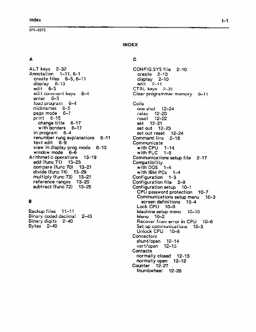
Index
GFK-0075
l-1
INDEX
A
ALT keys 2-32 Annotation l-11, 6-1
create files 6-5, 6-11 display 6-13 edit 6-3 edit comment keys 6-4 enter 6-3 load program 6-4 nicknames 6-5 .
page mode 6-7 print 6-15
change title 6-17 with borders 6-17
in program 6-4 renumber rung explanations 6-11 text edit 6-9 view in display prog mode 6-13 window mode 6-6
Arithmetic operations 13-19 add (func 71) 13-23 compare (func 70) 13-21 divide (func 74) 13-29 mutt iply (func 73) 13-27 reference t anges 13-20 subtract (func 72) 13-25
Backup files 11-11 Binary coded decimal 2-43 Binary digits Z-40 Bytes 2-40
C
CONFILSYS file Z-10 create Z-10 display Z-10 edit Z-11
CTRL keys 2-31 Clear programmer memory 9-11
Coi is one shot 12-24 relay 12-20 reset 12-22 set 12-21 set out 12-23 set out reset 12-24
Command line 2-18 Communicate
‘with CPU 1-14 with PLC 1-5
Communications setup file 2-17 Compatibility
with DOS 1-4 with IBM PCs 1-4
Configuration 1-3 Configuration file 2-9 Configuration setup 10-l
CPU password protection 10-7 Communications setup menu 10-3
screen definitions 1 o-4 Lock CPU 10-9 Machine setup menu lo-10 Menu 10-Z Recover from error in CPU 10-6 Set up communications 10-3 Unlock CPU 10-8
Connectors shunt/open 12-14 vert/open 12-15
Contacts normally closed 12-13 normally open 12-12
Counter 12-27 thumbwheel 12-28
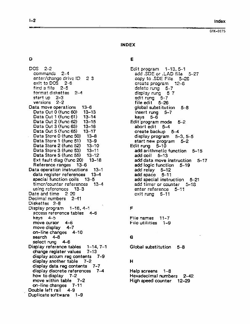
l-2 Index
DOS 2-2 commands 2-4 enter/change drive ID 2-3 exit to DOS 2-6 find a file 2-5 format diskettes 2-4 start up 2-3 versions 2-2
Data move operations 13-6 Data Out 0 (func 60) 13-13 Data Out 1 (func 61) 13-14 Data Out 2 (func 62) 13-15 Data Out 3 (func 63) 13-16 Data Out 5 (func 65) 13-17
- Data Store 0 (func 50) 13-8 Data Store 1 (func 51) 13-9 Data Store 2 (func 52) 13-10 Data Store 3 (func 53) 13-11 Data Store 5 (func 55) 13-12 Ext fault diag (func 20) 13-18 Reference 13-6 ranges
Data operation instructions 13-l data register references 13-4. special function coils 13-5 timer/counter references 13-4 using references 13-3
Date and time Z-20 Decimal numbers 2-41 Diskettes 2-8
% Display program 1-16, 4-1 access reference tables 4-6 keys 4-5 move cursor 4-6 move display 4-7 on-line changes 4-10 search 4-8 select 4-6 fung
Display reference tables l-14,7-1 change register values 7-l 3 display accum reg contents 7-9 display another table 7-2 display data reg contents 7-7 display discrete ref etences 7-4 how to display 7-2 move within table 7-2 on-line changes 7-11
Double left tail 4-9 . Duplicate software 1-9
UK-0075
INDEX
E
Edit program 1-13, 5-l add .SDE or .LAD file 5-27 copy to .SDE File 5-26 create program 12-6 delete rung 5-7 display rung 5-7 edit rung 5-7 file edit 5-26 global substitution 5-8 insert rung 5-7 keys 5-6
Edit ‘program mode 5-2 abort edit 5-4 create backup 5-4 display program 5-3, 5-5 start new program 5-2
Edit rung 5-10 add arithmetic function 5-l 5 add coil 5-13 add data move instruction 5-17 add logic function 5-l 9 add relay 5-12 add space 5-11 add special instruct ion 5-21 add timer or counter 5-l 8 enter reference 5-l 1 exit rung 5-11
F
File names 11-7 File utilities l-9
G w
Global substitution 5-8
Help screens 1-8 Hexadecimal numbers 2-42 High speed counter 12-29
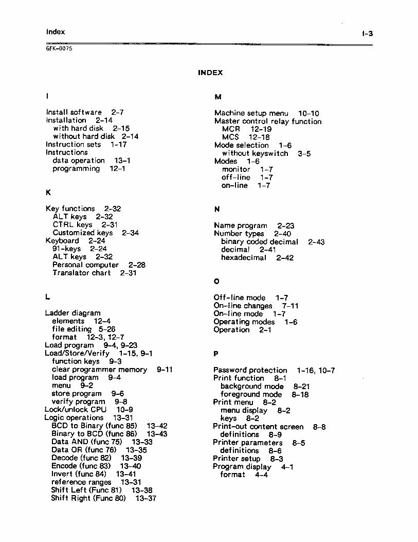
Index r-3
GFK-0075
I
lnstai I software 2-7 Installation 2-14
with hard disk 2-15 without hard disk 2-14
Instruction sets 1-17 instructions
data operation 13-l programming 12-1
K
Key functions 2-32 ALT keys 2-32 CTRL keys 2-31 Customized keys 2-34
Keyboard 2-24 91 -keys 2-24 ALT keys 2-32 Personal computer 2-28 Translator chart 2-31
L
Ladder diagram elements 12-4 file editing 5-26 format 12.3,12-7
Load program 9-4,9-23 Load/Store/Verify l-15, 9-1
function keys 9-3 clear programmer memory 9-11 load program 9-4 menu 9-2 store program 9-6 verify program 9-8
Lock/unlock CPU 1 O-9 Logic operations 13-31
BCD to Binary (func 85) 13-42 Binary to BCD (func 86) 13-43 Data AND (func 75) 13-33 Data OR (func 76) 13-35 Decode (func 82) 13-39 Encode (func 83) 13-40 her t (func 84) 13-41 reference ranges 13-31 Shift Left (Func 81) 13-38 Shift Right (Func 80) 13-37
Machine setup menu lo-10 Master control relay function
MCR 12-19 MCS 12-18
Mode select ion 1-6 without keyswitch 3-5
Modes mon off on-l
N
l-6- tor 1-7 ine l-7 ne 1-7
Name program 2-23 Number types 2-40
binary coded decimal 2-43 decimal 2-41 hexadecimal 2-42
Off-line mode 1-7 On-l ine changes 7-11 On-line mode l-7 Operating modes 1-6 Operation 2-1
Password protect ion l-1 6,1 O-7 Print function 8-1
background mode 8-21 foreground mode 8-18
Print menu 8-2 menu display 8-2 keys 8-2
Print-out content screen 8-8 definitions 8-9
Printer parameters 8-5 definitions 8-6
Printer setup 8-3 Program display 4-1
format 4-4
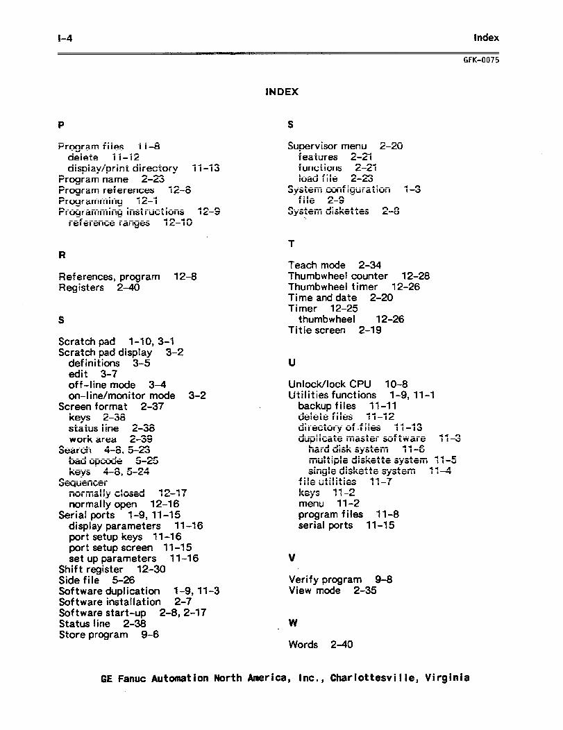
1-4 Index
P
Program files 11-8 delete 11-12 display/print directory 11-13
Program name 2-23 Program references 12-8 Programming 12-l Programming instruct ions 12-9
reference ranges 12-10
R
References, program 12-8 Registers 2-40
S
Scratch pad l-10, 3-1 Scratch pad display 3-2
definitions 3-5 edit 3-7 off-line mode 3-4 on-line/monitor mode 3-2
Screen format 2-37 keys 2-38 status I ine 2-38 work area 2-39
Search 4-8, 5-23 bad opcode 5-25 keys 4-8,5-24
Sequencer normally closed 12-17 normally open 12-16
Serial ports l-9,11-15 display parameters 11-l 6 port setup keys 11-16 port setup screen 11-15 set up parameters 11-16
Shift register 12-30 Side file 5-26 Software duplication 1-9, 11-3 Software installat ion 2-7 Software start-up 2-8, 2-17 Status line 2-38 Store program 9-6
GFK-0075
INDEX
S
Supervisor menu 2-20 features 2-21 functions 2-21 load file 2-23
System configuration l-3 file 2-9
System diskettes 2-8 0.
T
Teach mode 2-34 Thumbwheel counter 12-28 Thumbwheel timer 12-26 Time and date 2-20 Timer 12-25
thumbwheel 12-26 Title screen 2-19
U
Unlock/lock CPU 10-8 Utilities functions 1-9, 11-l
backup files 11-11 delete files 11-12 directory of -files 1 l-13 duplicate master software 11-3
hard disk system 11-6 multiple diskette system 11-5 single diskette system 11-4
file utilities 11-7 keys 1 l-2 menu 11-2 program files 11-8 serial ports 11-15
v
Verify program 9-8 View mode 2-35
W
Words 2-40
GE Fanuc Automation North America, Inc., CharIottesviIIe, Virginia


GE Fanuc Automation Notth America, Inc., Charlottesville, Wkghia ._

GFK-0075A
Related Documents