Logic and Digital Logic Logic and Digital Logic CPUs CPUs Patrice Koehl Computer Science UC Davis

Logic and Digital Logic CPUs
Dec 31, 2015
Logic and Digital Logic CPUs. Patrice Koehl Computer Science UC Davis. Basic Concepts (part II). Logic Proposition Operation on propositions Digital Logic The transistor Gates CPU Order of operations Speed. Basic Concepts (part II). Logic Proposition Operation on propositions - PowerPoint PPT Presentation
Welcome message from author
This document is posted to help you gain knowledge. Please leave a comment to let me know what you think about it! Share it to your friends and learn new things together.
Transcript

Logic and Digital LogicLogic and Digital LogicCPUsCPUs
Patrice KoehlComputer Science
UC Davis

Basic Concepts (part II)Basic Concepts (part II)
Logic◦Proposition◦Operation on propositions
Digital Logic- The transistor- Gates
CPU◦Order of operations◦Speed

Basic Concepts (part II)Basic Concepts (part II)
Logic◦Proposition◦Operation on propositions
Digital Logic- The transistor- Gates
CPU◦Order of operations◦Speed
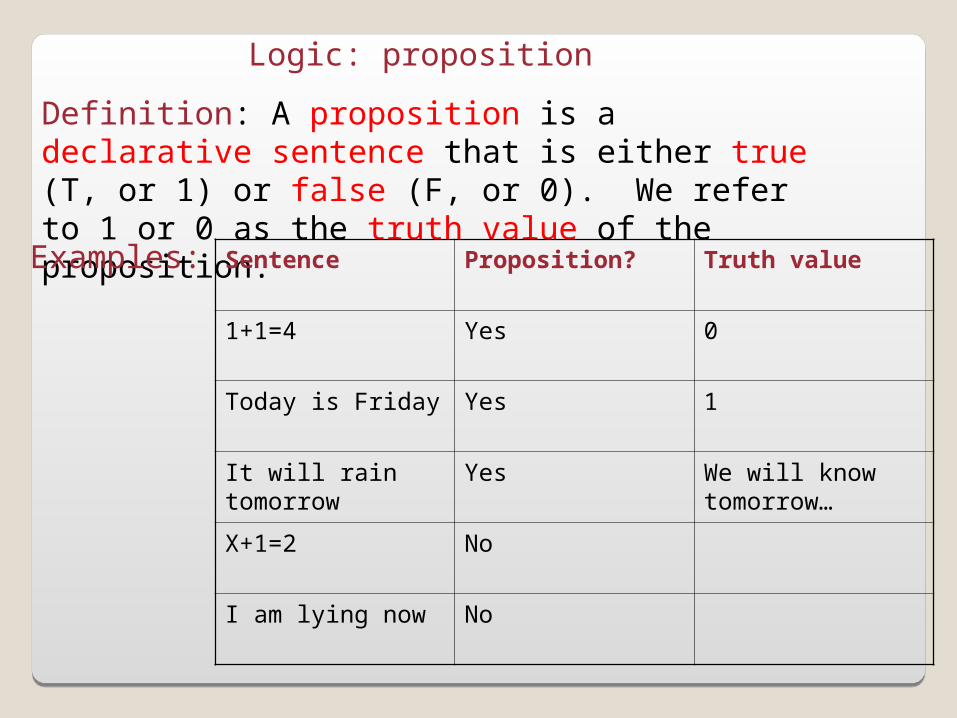
Logic: proposition
Definition: A proposition is a declarative sentence that is either true (T, or 1) or false (F, or 0). We refer to 1 or 0 as the truth value of the proposition.
Examples: Sentence Proposition? Truth value
1+1=4 Yes 0
Today is Friday Yes 1
It will rain tomorrow Yes We will know tomorrow…
X+1=2 No
I am lying now No
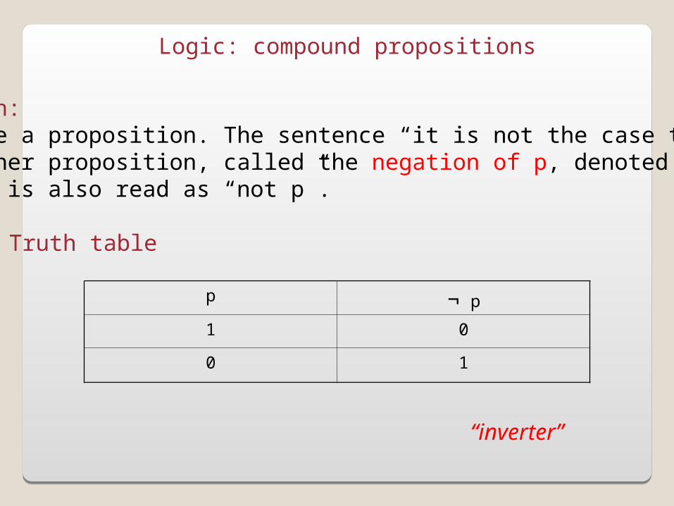
Logic: compound propositions
Negation:Let p be a proposition. The sentence “it is not the case that p” is another proposition, called the negation of p, denoted ¬p or~p. It is also read as “not p”.
Truth table
p ¬ p
1 0
0 1
“inverter”
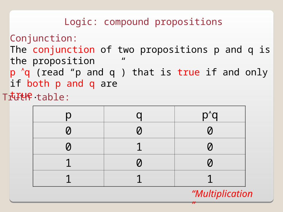
Logic: compound propositions
Conjunction:The conjunction of two propositions p and q is the propositionp q (read “p and q”) that is true if and only if both p and q aretrue.
Truth table:
p q pq
0 0 0
0 1 0
1 0 0
1 1 1“Multiplication”

Logic: compound propositions
Disjunction:The disjunction of two propositions p and q is the propositionp q (read “p or q”) that is true if and only if p or q, or both aretrue.
Truth table:
p q pq
0 0 0
0 1 1
1 0 1
1 1 1
“Addition”

Basic Concepts (part II)Basic Concepts (part II)
Logic◦Proposition◦Operation on propositions
Digital Logic- The transistor- Gates
CPU◦Order of operations◦Speed

The concept of pressure
When we remove the block, what is the effect on pressure?

The concept of pressure
Stays the same
Decreases

Electrical pressure: voltage
Vcc
Ground
Resistor
Switch
If switch is off (0) (equivalent tothe presence of the block)
Output
Voutput=Vcc high (i.e. 1)
If switch is on (1) (equivalent tothe absence of the block)
Voutput<<Vcc low (i.e. 0)
“Inverter”

The transistor
Base
Collector
Emitter
A transistor can be used as anelectronic switch:
-if Vbase is high, the current “flows” between the emitter and the collector (switch is on)
-If Vbase is low, the current does not pass (switch is off)

The not gate
Input: 0
1
Input: 1
0
Input Output
0 1
1 0

Input A Input B Output
1 1 0
1 0 1
0 1 1
0 0 1
The not-and (NAND) gate
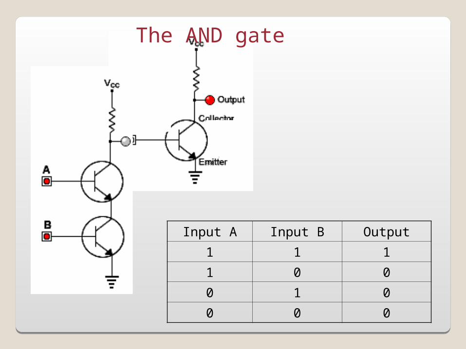
The AND gate
Input A Input B Output
1 1 1
1 0 0
0 1 0
0 0 0
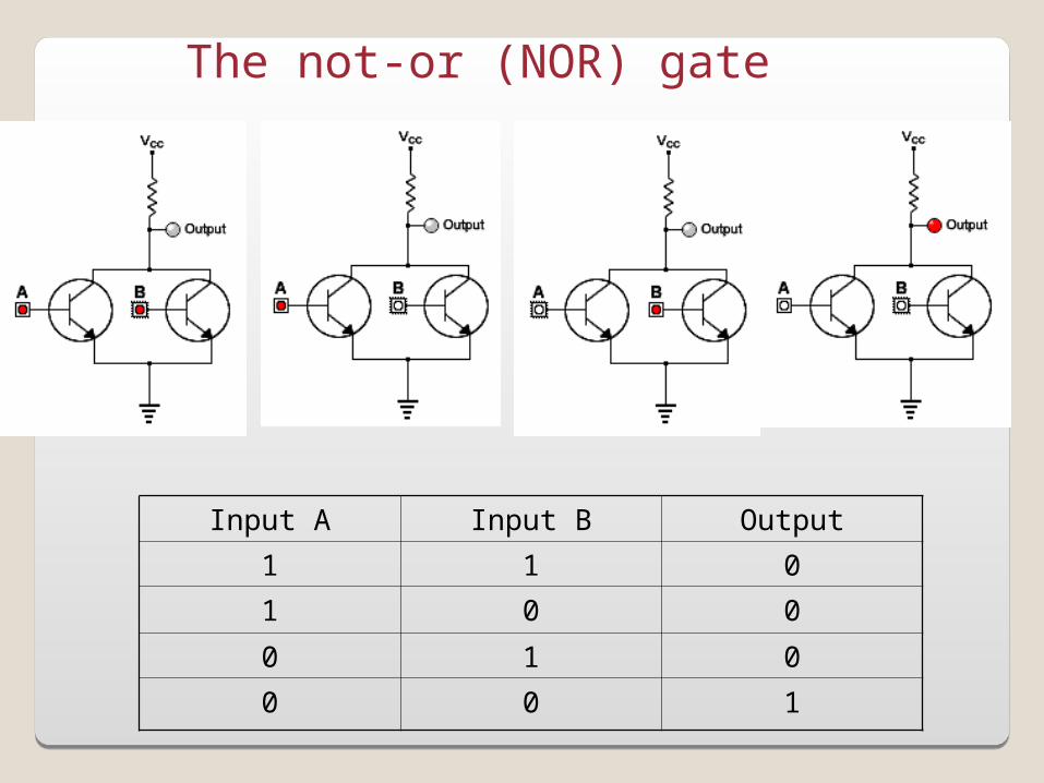
The not-or (NOR) gate
Input A Input B Output
1 1 0
1 0 0
0 1 0
0 0 1

The OR gate
Input A Input B Output
1 1 1
1 0 1
0 1 1
0 0 0
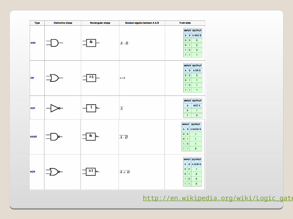
http://en.wikipedia.org/wiki/Logic_gate
Integrated Circuit- A computer central processing unit (CPU) is an electronic circuit combining millions of these logical digital gates and other electronic components.
-While the transistor was key to the development of computers, another major step was the possibility to miniaturized to the extreme the design of these electronic circuits: this was made possible by the invention of the Integrated Circuit (or IC, microcircuits, microchips, silicon chips or chips).
There has been several generations of IC:-SSI: small scale integration-MSI: medium scale integration-LSI: large scale integration-VLSI: very large scale integration
-Moore’s law (1965):“The complexity for minimum component costs has increased at a rate of roughly a factor of two per year. Certainly over the short term this rate can be expected to continue”


Basic Concepts (part II)Basic Concepts (part II)
Logic◦Proposition◦Operation on propositions
Digital Logic- The transistor- Gates
CPU◦Order of operations◦Speed

ALU Control
Memory
Input
Output
CPU
The Central Process Unit (CPU)
The CPU consists of three parts:-the Arithmetic Logic Unit (ALU)-The Control Unit-Memory
The Fetch/Execute Cycle
The CPU cycles through a series of operations or instructions,organized in a cycle, the Fetch/Execute cycle:
1. Instruction Fetch (IF)
2. Instruction Decode (DP)
3. Data Fetch (DF)
4. Instruction Execute (IE)
5. Result Return

Step 1: Instruction Fetch
Fetch instruction from memory position 2200:
Add numbers in memory positions 884 and 428, andstore results at position 800
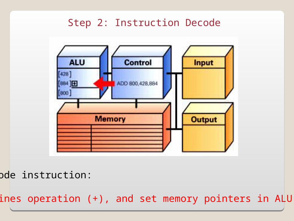
Step 2: Instruction Decode
Decode instruction:
Defines operation (+), and set memory pointers in ALU
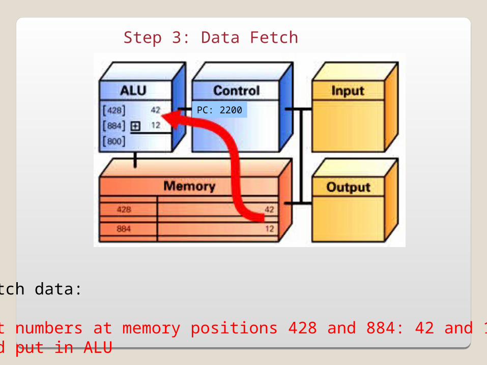
Step 3: Data Fetch
Fetch data:
Get numbers at memory positions 428 and 884: 42 and 12and put in ALU
PC: 2200
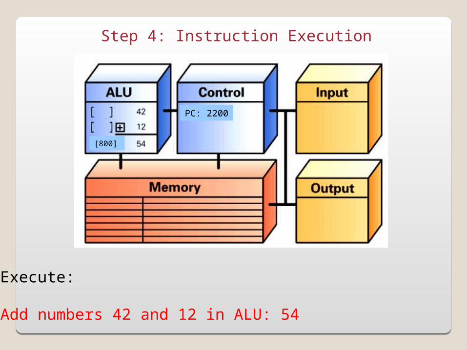
Step 4: Instruction Execution
Execute:
Add numbers 42 and 12 in ALU: 54
PC: 2200
[800]

Step 5: Return Result
Return:
Put results (54) in position 800 in memory
PC: 2200
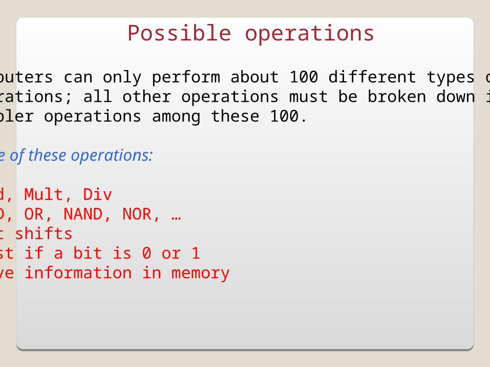
Possible operations
Computers can only perform about 100 different types ofoperations; all other operations must be broken down intosimpler operations among these 100.
Some of these operations:
-Add, Mult, Div-AND, OR, NAND, NOR, …-Bit shifts-Test if a bit is 0 or 1-Move information in memory-…

Repeating the F/E cycle
Computers get their impressive capabilities by performingmany of these F/E cycles per second.
The computer clock determines the rate of F/E cycles persecond; it is now expressed in GHz, i.e. in billions of cyclesper seconds!
Note that the rate given is not an exact measurement.
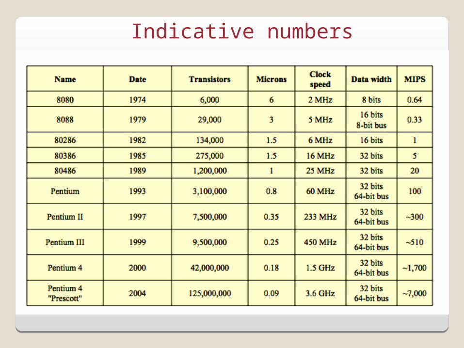
Indicative numbers

(http://en.wikipedia.org/wiki/Accelerating_change)

(http://en.wikipedia.org/wiki/Accelerating_change)
Related Documents