LOAD DISTRIBUTION IN EDGE-STIFFENING BEAM OF A SIMPLY SUPPORTED BRIDGE DECK IWAN PERMADI KUSUMA UNIVERSITI TEKNOLOGI MALAYSIA

Welcome message from author
This document is posted to help you gain knowledge. Please leave a comment to let me know what you think about it! Share it to your friends and learn new things together.
Transcript

LOAD DISTRIBUTION IN EDGE-STIFFENING
BEAM OF A SIMPLY SUPPORTED BRIDGE
DECK
IWAN PERMADI KUSUMA
UNIVERSITI TEKNOLOGI MALAYSIA

PSZ 19:16 (Pind. 1/97)
UNIVERSITI TEKNOLOGI MALAYSIA
BORANG PENGESAHAN STATUS TESIS LOAD DISTRIBUTION IN EDGE-STIFFENING BEAM OF ASIMPLY SUPPORTED BRIDGE DECK
SESI PENGAJIAN: 2004/2005
IWAN PERMADI KUSUMA (No. Passport : AG 674328)
Prof. Dr. AZLAN ABDUL RAHMAN

Prof. Dr. AZLAN ABDUL RAHMAN

LOAD DISTRIBUTION IN EDGE-STIFFENING BEAM OF A
SIMPLY SUPPORTED BRIDGE DECK
IWAN PERMADI KUSUMA
A project report submitted in partial fulfilment of the
requirements for the award of the degree of
Master of Engineering (Civil – Structure)
Fakulty of Civil Engineering
Universiti Teknologi Malaysia
March 2005

ii
I declare that this thesis entitled “Load Distribution In Edge-Stiffening Beam of a
Simply Supported Bridge Deck” is the result of my own Project
except as cited in the references. The thesis has not been accepted for any degree and
is not concurrently submitted in candidature of any other degree.
Tandatangan : ………………………
Nama Penulis : IWAN PERMADI KUSUMA
Tarikh : 18 March 2005

iii
ACKNOWLEDGEMENT
I am very grateful to Allah SWT for giving me the strength and the capability
to finish my master project dissertation. I wish to my sincere gratitude to my
supervisor, Prof. Dr. Azlan Abdul Rahman, of Faculty of Civil Engineering for his
guide, invaluable advice and useful suggestions during the conduct of this project.
Thanks are also due Ade and Wandi to helping me for any thing, to mak siti’s
family (along, anem, dura, vivi and ame), and to my friend in PPI for their generous
support. Many thanks to Nasir and Dony for help in the printing of the document.
Specially thanks to my beloved wife Sita Nurmari Putri Utami in yogyakarta,
and heartiest gratitude to my parent (Murtadi,- Sri Permata and Soegijanto – Sudi
Nurtini) as well as to my siplings (Mbak Angie- Mas Zain – Tole Ilham , Dik Epi
and Dik Inda) for their moral and the spiritual support throughtout my studies.
IWAN PERMADI KUSUMA
MARCH, 2005

iv
ABSTRACT
This study involves two distinct methods for analysis of a simply supported
bridge deck with or without edge-stiffening beam and the effect of edge-stiffening on
the longitudinal and transverse moments along the deck. An analysis of a slab bridge
with or without edge-stiffening beams is made and the result obtained from LUSAS
programs (Finite Element Method) are compared with those derived theoretically
(Load Distribution Method). The analysis considered HB loading acting on deck
bridge. The analysis is confined to the case where the effective depth of the bridge is
constant between the edge-stiffening. The degree of accuracy to be expected from the
theoretical analysis and the difference in the longitudinal and transverse bending
moment due to the effect of edge-stiffening beams are estimated. Part of the analysis
for the above problems involves the determination of longitudinal moment in the
corner or edge-stiffening beam.

v
ABSTRAK
Studi ini melibatkan dua metoda yang beda untuk analisa suatu jembatan
yang disokong secara mudah, dengan atau tanpa pengukuhan tepi (ketebalan di
samping jembtan) dan efek dari pengukuhan tepi pada gaya momen yang membujur
dan melintang sepanjang geladak itu. Suatu analisa dari papan jembatan dengan atau
tanpa pengukuhan tepi dibuat dan hasilnya diperoleh dari program LUSAS (Metode
Unsur Tak Terhingga) dibandingkan dengan hasil yang diperoleh secara teoritis
(Metoda Distribusi Beban). Analisa mempertimbangkan beban HB yang berada di
atas jembatan. Analisa terbatas pada kasus di mana ketebalan efektif dari jembatan
adalah tetap diantar pengukuhan tepi. Derajat ketepatan yang diharapkan dari analisa
secara teoritis dan perbedaan pada gaya momen yang membujur dan melintang
akibat dari adanya pengukuhan tepi dapat diperkirakan. Bagian dari analisa untuk
permasalahan di atas melibatkan penentuan dari gaya momen membujur di sudut
atau balok untuk pengukuhan tepi.

vi
CONTENTS
CHAPTER ITEM PAGE
ACKNOWLEDEMENT iii
ABSTRACT iv
ABSTRAK v
CONTENTS vi
LIST OF TABLES x
LIST OF FIGURE xi
LIST OF SYMBOLS xiv
LIST OF APPENDICES xv
PART ONE
INTRODUCTION
CHAPTER I INTRODUCTION 1
1.1. General 1
1.2. Importance of Study 2
1.3. Objectives of Study 2
1.4. Scope of Study 3
1.5. Methodology 3

vii
PART TWO
LITERATURE REVIEW
CHAPTER II METHODS FOR BRIDGE DECK ANALYSIS 6
2.1. Introduction 6
2.2. Types of Bridge Deck Construction 6
2.2.1 Solid Slab Deck 7
2.2.2 Voided Slab Deck 8
2.2.3 Beam-and-Slab Deck 9
2.3. Bridge Loading 10
2.4. Load Distribution Method 12
2.4.1 Distribution Coefficients 15
2.4.2 Maximum Longitudinal Moments 17
2.4.3 Maximum Transverse Moments 19
2.5. Finite Element Method 21
2.5.1 General Description of Method 22
2.5.2 Finite Element Program (LUSAS) 23
2.5.3 Input and Output 24
PART THREE
METHODOLOGY
CHAPTER III EDGE-STIFFENING IN CONCRETE BRIDGE DECKS 26
3.1. Introduction 26
3.2. Forms of Edge-Stiffening 26
3.3. Analytical Solution for Effect of Edge Stiffening 28
3.4. General Effects of Edge-Stiffening 31

viii
PART FOUR
RESULT AND DISCUSSION
CHAPTER IV CASE STUDY ON EFFECT OF EDGE-STIFFENING USING
LOAD DISTRIBUTION METHOD 35
4.1. Introduction 35
4.1.1 Deck Geometry (Case Study 1, 2, 3) 35
4.1.2 Loading 37
4.1.3 Moments 38
4.2. Results for Case 1 39
4.3. Results for Case 2 44
4.4. Results for Case 3 50
CHAPTER V ANALYSIS OF EFFECT OF EDGE-STIFFENING USING
FIFNITE ELEMENT METHOD 54
5.1 Introduction 54
5.1.1 Description of LUSAS Program 54
5.1.2 Deck Idealization (Case Study 1a, 2a, 3a) 55
5.1.3 Finite Element Model and Mesh Layout 55
5.1.4 Element Properties 55
5.1.5 Loading 56
5.1.6 Moment 56
5.2 Results for Case 1a 57
5.3 Results for Case 2a 58
5.4 Results for Case 3a 59

ix
CHAPTER VI DISCUSSION OF RESULTS 60
6.1 Result of both method 60
6.2 General Effect of Edge-Stiffening 63
6.3 Form of Edge-Stiffening 63
6.4 Method of Analysis 63
PART FIVE
CONCLUSION
CHAPTER VII CONCLUSIONS 65
7.1 General Conclusions 65
7.2 Recommendations for Future Work 66
PART SIX
REFRENCES
REFRENCES 67
PART SEVEN
APPENDICES
APPENDICES 68

x
LIST OF TABLE
TABLE NO. TITLE PAGE
2.1
4.1
4.2
4.3
4.4
4.5
5.1
5.2
5.3
6.1
6.2
Unit of HB loading
Value of Kmx0.25
Statical equivalent load position
Value of 25.0
Distribution coefficient
Statical equivalent load position
Maximum the bending moment for slab without edge
stiffening
Maximum bending moment for slab with edge stiffening
for Case 2a
Maximum bending moment for slab with edge stiffening
for Case 3a
Result of longitudinal and transverse moment with Load
Distribution Method
Result of longitudinal and transverse moment with Finite
Element Method
11
40
41
42
43
45
57
58
59
60
60

xi
LIST OF FIGURE
FIG. NO. TITLE PAGE
2.1
2.2
2.3
2.4
2.5
2.6
2.7
2.8
2.9
2.10
2.11
2.12
2.13
3.1
3.2
Cross section of bridge and solid slab deck
Cross section of bridge and voided slab deck
Cross section of bridge and slab deck: (a) T - beam bridge,
(b) Slab on steel beams, (c) Slab on prestress concrete
beams
HB Loading
HB in 1 National Lane
HB in 2 National Lane
Actual and effective width of deck
Standard positions or Reference Station
The positions of load: (a) The positions of the effective
width 2b, (b). Equivalent load positions
Typical distribution coefficient profiles for abnormal
loading
Position of wheels for maximum transverse moment at
centre of bridge
Elements type
Finite Element System
The form of edge stiffening of slab. (a) Edge beam
centroids on mid plane of slab. (b) edge beam centroids
above mid span of slab.
The modifity form of edge stiffening of slab. (a) Concrete
7
8
10
10
11
11
12
13
16
18
18
20
22
24
27

xii
3.3
3.4
4.1
4.2
4.3
4.4
4.5
4.6
4.7
4.8
4.9
5.1
5.2
5.3
5.4
5.5
6.1
box girder. (b) Steel buckle plate (c) Prestressed inverted
T-beam (composite) (d) Steel through deck
(a) Bridge considered in analysis. (b) Forces and moments
acting on bridge and edge beams
Superposition of symmetrical and asymmetrical edge
moments to obtain desired edge moments
Shows the dimension of the plan of concrete bridge deck
(a) Case study 1and (b) Case study 2 and 3
Cross section of bridge slab deck (a) Case study 1, (b) Case
study 2, (c) Case study 3
The arrangement of live load on plan on the deck for
longitudinal
The arrangement of live load on plan on the deck for
transverse
The condition maximum for longitudinal moment
The condition maximum for transverse moment
Distribution coefficient for actual load positions under the
wheels
Force acting on slab bridge at mid-span
Load positions and equivalent loads for maximum
transverse moment
The finite element model for the plan deck (a) without and
(b) with edge-stiffening
The model of HB loading in finite element (a) position for
longitudinal moment and (b) position for transverse
moment
Moment distribution in both directions for Case 1a
Moment distribution in both directions for Case 2a
Moment distribution in both directions for Case 3a
Shows the comparison between Case 1, 2 and 3 in
maximum bending moment of the longitudinal beams and
transverse bending moment for load distribution method
27
28
29
36
36
37
38
38
39
43
45
48
55
56
57
58
59
61

xiii
6.2
6.3
Shows the comparison between Case 1, 2 and 3 in
maximum bending moment of the longitudinal beams and
transverse bending moment for finite element method
Shows the comparison between load distribution method
and finite element method for Case 1, 2 and 3 in maximum
bending moment of the longitudinal beams and transverse
bending moment
61
62

xiv
LIST OF SYMBOLS
2a - Span Bridge
2b - Width Bridge
d - the slab depth
E - Young's modulus of the material of deck
G - modulus of rigidity or torsional modulus of the material of the deck
i - longitudinal second moment of area of the equivalent deck per
unit width
I - second moment of area of each longitudinal girder
io - longitudinal torsional stiffness per-unit length
j - transverse second moment of area of the equivalent deck
per unit length
J - the second moment of area of each transverse diaphragm or
cross beam
jo - transverse torsional stiffness per unit length
Ka - the distribution coefficient for the actual value of a.
Ko - distribution coefficient for a equal to 0.
K1 - distribution coefficient for a equal to 1.
lo - torsional stiffness constant of a longitudinal girder
p - spacing of longitudinal girders
q - spacing of stiffners i.e. diaphragms or cross beams

xv
LIST OF APPENDICES
APPENDIX TITLE PAGE
A
B
C
Coefficient of Lateral Distribution
Distribution Coefficient
Transfer Moment Coefficient
68
71
81
CHAPTER I
INTRODUCTION
1.1 General
A bridge is a permanent raised structure which allows people or vehicles to
cross an obstacle such as a river without blocking the way of traffic passing
underneath (Heinz Kurth 1976). And the construction of bridge comprises one
section of the work of the civil engineering which was has an immediate impact upon
the public. The reasons of the impact are not hard to find since most major bridge
combine a strong visual impression together with obvious benefit in the way of
improved communication.
Many bridges are designed to incorporate some forms of edge stiffening for
the need to accommodate services of various types, or deal with narrow or negligible
footpaths, (which permit excessive eccentricities of abnormal loads) or, in the case of
a railway over bridge, to provide a parapet specifically to prevent accidents.
Whatever the reason for its presence, the edge stiffening will considerably affect the
behaviour of the bridge structure under load and, of more importance; it can improve
the distribution characteristics of the bridge with regard to longitudinal moments.
However, the beneficial effects of edge stiffening can only be obtained by
ensuring a positive structural connection between any edge stiffening and the main
bridge structure and by analyzing in detail the entire structure. On the other hand
cases exist where the effective transverse stiffness of the main bridge structure is
maintained to the parapet beams. Then the effect of the stiffness beams at the edges

2
should be ignored. No theoretical analysis at present available to cover this particular
aspect of bridge design, though Massonnet [4] has extended his distribution analysis
to allow for the effect of edge beams in which no torsional stiffness is present.
Load distribution analysis includes the effect of torsion and covers the range
from a no torsion grillage to a full torsion slab. From this analysis it is possible to
assess the effect of torsion in the edge beams at the design stage and hence it will be
for the designer to use his judgement in deciding whether or not to include the
torsional effect. If the torsion is neglected, the analysis will yield results which would
be identical to those obtained by Massonet.
1.2 The Importance of the Study
The study will address some of the important aspect as follows:
The development of load distribution in edge-stiffening beam of a simply
supported bridge deck.
The analysis of bending moment in a bridge deck using load distribution
coefficients method and finite element method for comparison.
The example of design of a selected structure is illustrated.
To comparison of bending moments in bridge deck with edge-stiffening and
without edge stiffening.
1.3 Objectives
The objectives of this study are as follows:
To study various forms of edge-stiffening in concrete bridge deck

3
To analyse the bending moment in a bridge deck with and without edge
stiffening using load distribution coefficient (manual method) and finite
element method
To compare maximum moments in a bridge deck with and without edge
stiffening
1.4 Scope of the Study
In the beginning, complete sets of information on concrete deck bridge being
used and applied in Malaysia is collected. The public Work department ministry of
work and Malaysia provide all data about standard design of concrete deck bridge.
And the standard design is the studied. Several parameters which need to be studies
are finalized. Finally, the structures are modeled, in the putted with the different sets
of parameter and analysis using finite element software. LUSAS finite element
software has been used in the study. The scope of this study is:
A single span simply supported bridge
Effect of 45 unit HB live load only (BS 5400).
1.5 Methodology of the Study
In this project, the steps taken in studying load distribution in Edge-stiffening
beam of a simply supported bridge deck can be summarized into several steps as
below:

4
Problem Identification and Definition
Identify the problem through reading, discussion and observation of the
area studied.
Understand the background of the problem through literature studies.
Study the feasibility and the needs to carry out the research topic and the
scope.
Identify the title, scope, aim and objectives of the project.
Plan the methodology for the project.
Literature Survey
Search information from book, journals, articles, thesis, seminar notes or
conference paper, and internet.
Review of the various type of the bridge deck.
Understand the principles of load distribution.
Understand the basic principles of maximal bending moment in
longitudinal and transverse.
Understand the basic principles of the application of LUSAS programs.
Edge-Stiffening in Concrete Bridge Deck Analysis
Review the form of edge-stiffening.
Understand the basic steps analytical solution of edge-stiffening
Understand the principles effected of edge stiffening.
Design of deck
Deck without edge-stiffening beam.
Deck with edge-stiffening beam use form edge-stiffening 1.
Deck with edge-stiffening beam use form edge-stiffening 2.

5
Case Studies
Carry out the edge-stiffening on three selected case studies.
Calculate using load distribution method.
Calculate using Finite Element Method
Interpret the result of the analysis
Discussion
Discuss of comparison of the case studies.
Conclusions and Recommendations
Write an overall conclusion for this project. Give some recommendations for future research or project.

CHAPTER II
METHOD FOR BRIDGE DECK ANALYSIS
2.1 Introduction
2.2 Type of bridge Deck Construction
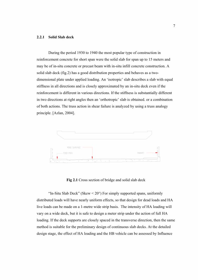
2.2.1 Solid Slab deck
Fig 2.1

2.2.2 Voided Slab Deck
Fig. 2.2

2.2.3 Beam and Slab Deck

Fig 2.3
2.3 Bridge Loading

1 m
3.5 moverallwidth
1 m
whichever dimensionproduces the most severeeffect on the memberunder consideration
6, 11, 16, 21 or 25 m1.8 m 1.8 m
axleUnits
1 m
CL
WheelaxleLC
axleLC
axleLC
Fig 2.4
Table 2.1
Central reserve No loading for global analysis
Overall vehiclelength for axlespacing having
most severe effect
Loaded length for intensity of HA UDL
Lane
Load
ing
are
inte
rcha
nge
a ble
for
mos
tse
vere
effe
ct
1/3 HA
1/3 HA
1/3 HA
No LoadingFull HA UDL HB vehicle
Full HA
1/3 HA
25 m
Nationallanes
No Loading Full HA UDL
25 m Nationallanes
Fig 2.5

are
inte
rcha
nge
abl e
for
mos
tse
vere
eff e
ct
1/3 HA
1/3 HA
1/3 HA
Central reserve No loading for global analysis
Full HA UDL
Full HA UDL
Overall vehiclelength for axlespacing having
most severe effect
1/3 HA
HB vehicleNo Loading 3.5 No Loading
Loaded length for intensity of HA UDL
25 m 25 m
Nationallanes
Full HA UDL
Full HA UDL
Nationallanes
Or vice-versaNational lanes
Nationallanes
are
inte
rcha
nge
able
for
mos
tse
vere
e ffe
ct
Central reserve No loading for global analysis
1/3 HA
1/3 HA
1/3 HA
Loaded length for intensity of HA UDL
Full HA UDL
1/3 HA UDLNo Loading
Or vice-versa 25 m
Overall vehiclelength for axlespacing having
most severe effect
No Loading3.5HB vehicle
Full HA
Full HA UDL
1/3 HA UDL
25 m
or
Fig 2.6
2.4 Load Distribution Method

Fig. 2.7

j
ix
a
b
a
b
p
Ii
q
Jj
dji

ixjxEx
jiGx oo
p
looi
2.4.1 Distribution Coefficients

Fig. 2.8
KKKK o

2.4.2 Maximum Longitudinal Moments

P1 32P P 4P
P P P P
b
andnn
(a)
(b)
Fig. 2.9
2.
Fig. 2.10 5
2.0
1.5
Ko-0.5
VA
LUE
OF
K
1.0
0.5
0
K1
K
REFERENCE STATION
b 3/4b b/4b/2-1.0
-b/2-b/40 -3/4b -b

b
p
b
p
2.4.3 Maximum Transverse Moments

Fig. 2.11
n a
xnbHnny
n n
a
xn
n
a
un
a
un
a
un
a
un
aHn

u u u u
a
u
a
u
a
u
a
u
a
bMy
a
u
a
u
a
u
a
u
etca
u
a
u
a
u
a
u
nnnn
2.5 Finite Element Method

2.5.1 General Description Of Method
Fig 2.12

2.5.2 Finite Element Program (LUSAS)
Volumes Surfaces Lines
Combined Lines Points

Pre-Processing Results-Processing
Finite Element Solver
Fig. 2.13
2.5.3 Input and Output

Ü Ü Ü
Ü
Ü

CHAPTER III
EDGE-STIFFENING IN CONCRETE BRIDGE DECKS
3.1 Introduction
A slab deck is able to carry a load near an edge if the edge is stiffened with a
beam. Additional of edge stiffening beam can influence the behaviour of bridge
structure.
3.2 Forms of Edge-Stiffening
Many contemporary bridges are constructed with some form edge-stiffening
in the form of deeper edge beams, fascia beams and increased structural depth for the
sidewalk slab. Figure 3.1 (a) shows a slab deck with edge stiffening beam which
have their centroids on the mid plane of the slab. The bending inertias of such beams
are calculated about the mid plane of the slab and the beam sections are fully
effective. Improved edge stiffening is achieved if the beams do not have their
centroids on the mid plane of slab as in figure 3.1(b) because the beams then act as L
beams with the slab deck acting to some extent as a flange. Under bending action, the
neutral axis remains near the mid plane of the slab in the central region and rises
towards the edges. The width of the slab that acts as flange to the edge beam is
restricted by the action of shear lag. And the modification of form edge stiffening as
show in figure 3.2

27
Figure 3.1 The form of edge stiffening of slab. (a) Edge beam centroids on midplane of slab. (b) edge beam centroids above mid span of slab.
(a)
(b)
(c)
(d)
Figure 3.2 The modifity form of edge stiffening of slab. (a) Concrete box girder. (b) Steel buckle plate (c) Prestressed inverted T-beam (composite)
(d) Steel through deck

28
3.3 Analytical Solution for Effect of Edge Stiffening
Consider the bridge with edge stiffening beams in Figure 3.3 (a). Let the span
of the bridge be 2a, the width of the uniform section of the bridge (i.e. excluding
width of edge beams) be 2b, the stiffness per unit length of the longitudinal section
be the second moment of area of the edge beams be and the torsional stiffness
of the edge beams be . The applied loading is represented by the four equal
loads P.
E E
EGJ
The edge beams can be isolated from the remainder of the bridge and edge
shear forces and moments introduced as shown in Figure 3.3 (b). These shear forces
and edge moments are assumed to be distributed sinusoid ally along the span.
The bridge can now be analysed using the results obtained in the previous
sections and the unknown shear forces F1 and F2 edge moments M1 and M2
determined from the compatibility equations for deflection and slope at the edges y=
+ b.
(a)
(b)
Figure 3.3 (a) Bridge considered in analysis. (b) Forces and moments acting
on bridge and edge beams
The shear forces F1 and F2 can be treated as applied loads on the bridge and
hence the deflection at the edge y=b due to all the applied loads can be written:

29
bbP
bby b
F
b
F
a
xaduetoP
a
x
b
aW
222sin
16
2sin
2
16 214
41
4
4
1 ……… (3.1)
Where H1 is the amplituded of the first term in the Fourier series for the applied
loads P.
The edge M1 and M2 can be considered in the form shown in Figure 3.4. This
method of superposing symmetrical edge moments enables the coefficients to be
used. Thus the deflection at the edge y=b due to the edge moments can be written:
a
xbbW b
Eb
Eby 2
sin'22
221
221
1 ……..…… (3.2)
Figure 3.4 Superposition of symmetrical and asymmetrical edge moments to obtain
desired edge moments.
The total deflection, give by the sum of equations (3.1) and (3.2), must equal
that of the edge beam at y=b under the action of the loading F1a
x
2sin . Therefore for
compatibility of deflection the following equations must be satisfied:
bbbEE b
F
b
FduetoP
ba
xa
a
xF
EI
a
2222sin
16
2sin
16 2114
4
14
4
ba
xbb
E
'2
sin2 2121
2
……..…… (3.3)

30
Similarly at y = -b:
bbbE b
F
b
FduetoP
ba
xa
a
xF
EI
a
2222sin
16
2sin
16 2114
4
24
4
ba
xbb
E
'2
sin2 2121
2
……..…… (3.4)
For slope compatibility at the edge y=b, it is found that for the bridge:
bbbaEby
FFduetoPx
s
a
y
W'''
2sin
`211
21
bbaE
xb'
2sin
2 2121 ………….…..…… (3.5)
For the torsional of the edge beam subjected to a twisting moment varying
sinusoid ally over the span, the angle of twist at any point may be determined by
considering the equilibrium condition of the edge beam with restraining couples
applied at its junction with the support diaphragms. Thus the edge beam rotation at a
distance x from the abutment may be shown to be.
a
a
E
x
GJ 2sin
22
1 ……………………….…….…..…… (3.6)
The compatibility equation for slope at y=b is therefore:
bbbaEa
a
E
FFduetoPxax
GJ'''
2sin
2sin
2211
22
1
bbaE
xb21212
sin2
…….…..… (3.7)
And similarly at y=-b:
bbbaEa
a
E
FFduetoPxax
GJ'''
2sin
2sin
2211
22
2
bbaE
xb21212
sin2
…….….…… (3.8)

31
Equations (3.3), (3.4), (3.7) and (3.8) enable the unknown edge effects, F1, F2,
M1and M2 to be determined. For this purpose it is sufficient to consider the mid-span
section of the bridge, i.e. x = a. Once these values have been determined the
deflections, the longitudinal and transverse moments at any point in the bridge, and
the bending and torsional moments at any point in the edge beams may be
determined by superposing the various effects.
To obtain a fully rigorous solution it would be necessary to consider the
various terms in the Fourier series for the load ; this would imply using values of the
coefficients K,K’, ,,,', and ' appropriate to values of the flexural parameter
of .,3,2, etc This would involve solving the compatibility for each term. The
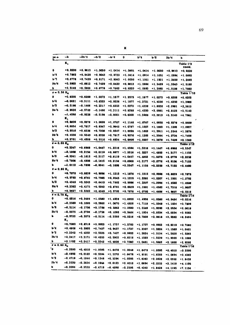
values of the coefficient are given in Graph 14-19.
At the junction of the edge stiffening and the main bridge structure an
implicit assumption has been made concerning the neutral axis. This that the natural
axis coincides in both the bridge and the edge stiffening member ; if any design it
does not then additional stresses will be set up locally which will modify, to a limited
extent, those given by the above analysis. Calculation of these stresses is not
practicable and nominal reinforcing steel should be included to cover this effect. In
general, however, the primary stresses in both the bridge and the edge beam will be
in accord with the above analysis.
In certain cases where the edge stiffening members is of considerable width
the edge shear forces, F, will induce both deflection and rotation of the edge
stiffening member. This effect can obviously be included in the above analysis if it
appears to be of significance.
3.4 General Effects of Edge-Stiffening
The detailed method of analysis given in the preceding sections can deal
satisfactorily with any of the edge conditions met in practice. However, in some

32
cases the full analysis may not be necessary and it then is sufficiently accurate to
consider only the effect of the edge shear forces F. In this case only deflection
compatibility need be considered at the two edges y = + b for this analysis only the
distribution coefficients K are required and the analysis may be out by omitting the
terms involving M1 and M2 in equations (3.3) and (3.4)
From experimental work that has been carried out it appears that the edge
moments may be neglected in the analysis when the ratio of the flexural to the
torsional stiffness of the edge beam is greater than about 5 provided that the flexural
stiffness/unit width of the edge beam is not considerably greater than that of the
equivalent orthotropic plate.
In general the effect of moderate edge stiffening is to reduce the maximum
longitudinal moments by between 20 and 30 per cent and to increase the maximum
transverse moments by about 5 per cent. The reduction in the longitudinal moments
is attributing able to :
(a) the decrease in the “ mean “ moment caused by the additional stiffness at the
edges, and
(b) the reduction in the maximum distribution coefficient due primarily to the edge
shear forces.
As in most engineering problems, the compatibility equations lead to a set of
simultaneous equations which tend to be ill-conditioned. Care should therefore be
exercised in solving these equations ; it is best to determine F1 and F2 first and
subsequently to back-substitute these values in the original equations to determine
M1 coefficients are approximately unity or less. It is also preferable to carry out the
solution on a desk calculating machine rather than a slide rule since a greater number
of decimal places can be used.
The method of analysis presented is in series form and therefore a rigorous
solution may only be obtained by considering the various terms in the series for the
applied load, edge shear forces and edge moments. By considering the centre of the
bridge, i.e. = a only the odd terms need be summed. While the first, third and fifth
terms of the series will led to a reasonably accurate solution, this implies solving
there sets of compability equations. This procedure may, in special circumstances, be

33
warranted but for most practical problems it is sufficiently accurate to consider only
the first term of the various series and apply certain correcting factors to the solution
so found.
If only the first term is used for the applied loads, edge shears and edge
moments and the compatibility equations for deflection and slope are solved, then the
deflection of both the edge beams and the bridge structure can be predicted with an
accuracy of within about 3 per cent. This follows from the consideration of Fourier
representations of various types of loading.
For the longitudinal moments, the Fourier representation does not given the
same accuracy as for deflection owing to the double differentiation involved.
However, the relation between the first term of the Fourier series for the “mean “
moment and the exact “ mean “ moment derived in the manner. Hence a factor can
be introduced to correct for the consideration of the first term only in the “mean “
moment. The same factor will be applicable to the edge shear forces F since Fouries
series for these are of the same form as that for the applied load. The second
correcting factor arises because only the first term is considered for the distribution
coefficient K; this factor of 1.1, but it must be noted that it only applies to the region
of maximum moment under or near the applied loads.
The design office analytical procedure for longitudinal moments may be
summarized as follow:
a) For the specific bridge and edge beams, derive the deflections and slope
compatibility equations and solve for the values of F and M applicable to the
first term of all the series involved;
b) Knowing F and H1derive the longitudinal moments at the standard positions due
to both the applied loads edge shear forces using the “ mean “ moment
appropriate to the first term of the series ; in this procedure the edge moments
are ignored since they give rise to no significant longitudinal moments;
c) Obtain the relation between the “ mean “ moment for the applied loading
deduced from the first term of the series, i.e. H1, and the exact procedure ;
d) Increase or decrease the total moments in (b) by the correcting factor found in
(c)

34
e) Increase the maximum moment found in (d) by 10 per cent.
For the transverse moment, therefore the relation between the total transverse of
the various terms in the series and therefore the relation between the total transverse
moment and that given by the first term of the series is known. This same relation
must apply to the transverse moment caused by the first term of the edge shear force
series; the total transverse moment can be derived.

CHAPTER IV
CASE STUDY ON EFFECT OF EDGE-STIFFENING USING LOAD
DISTRIBUTION METHOD
4.1 Introduction
4.1.1 Deck Geometry (Case study 1,2,3)

Fig. 4.1
Fig. 4.2

4.1.2 Loading
Fig. 4.3

Fig. 4.4
4.1.3 Moment
Fig. 4.5

Fig. 4.6
4.2 Result for Case 1
a
b
Longitudinal bending moment, Mx

Table 4.1

Table 4.2
xPxRA
P

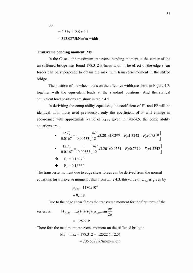
Transverse bending moment, My
Table 4.3

Fig. 4.7
Table 4.4

xxxx
My
4.3 Result for Case 2
bhi
mx
i
xhxbj
mxxx

Ex
xE
di
mi
bi
mi
Fig. 4.8

a
u
a
PH
xa
PH
bKbFKbbFbKpHI
ibF
bKbFKbbFbKpHI
ibF
xFxFxxPF
xFxFxxPF
Longitudinal bending moment, My

Kb
HaMx
a
x
xa
PH
a
Px
bx
aMx
PxxMx
b
Fx
a
xx
b
Fx
a
Pxx
Transverse bending moment, My

Fig. 4.9

Table 4.5
xFxFxxPF
xFxFxxPF
a
xxxFFbxM y

4.4 Result for Case 3
bhi
mx
i
xhxbj
mmxxx
Ex
xE
di
mi

bi
mi
a
u
a
PH
xa
PH
xFxFxxPF
xFxFxxPF

Longitudinal bending moment, My
Kb
HaMx
a
x
xa
PH
a
Px
bx
aMx
Pxx
xMx
b
Fx
a
Pxx
b
Fx
a
Pxx
Transverse bending moment, My
xFxFxxPF
xFxFxxPF
a
xxxFFbxM y

CHAPTER V
ANALYSIS OF EFFECT OF EDGE-STIFFENING USING FINITE
ELEMENT METHOD
5.1 Introduction
Today’s computer technology allows designs to be assessed much more
easily and quickly. Evaluating a complex engineering design by exact mathematical
models, however, is not a simple process.
5.1.1 Description of LUSAS Program
Compare to other FEM soft wares, LUSAS finite element software is very
user friendly. This software works in the window version, which is much simpler and
easier to use compared to other software. In the windows, the structures can be
modeled graphically and this is very helpful, especially to enable the user to view
and understand the models thoroughly.
By using the LUSAS software, both linear and non-linear analyses can be
performed. The attributes of the models are easy to create and they can be easily
assigned to the models by simply dragging the attributes’ icons to the models. This
finite elements software can model the concrete and steel structures, as long as their
material properties are known.

55
5.1.2 Deck Idealization (Case Study 1a, 2a, 3a)
A simply supported bridge structure consisting of an in-situ slab deck is to be
analysed. The geometry of the deck is as shown in Figure 4.1 and 4.2 in chapter IV.
5.1.3 Finite Element Model and Mesh Layout
LUSAS models are defined in terms of geometric features which must be
sub-divided into finite elements for solution. In this case regular meshing is used
with uniform spacing for beam and slab. Quadrilateral elements are used in this case
analysis, while for the generic element type thick shell is used and linear interpolar
linear order. Transitions pattern is used for the regular mesh. Figure 5.1 shows the
finite element model for the deck with and without edge-stiffening beam.
XY
Z (a) (b)XY
Z
Fig 5.1 The finite element model for the plan deck (a) without and (b) with edge-stiffening
5.1.4 Element Properties
Every part of a finite element model must be assigned a material property
dataset. LUSAS material datasets are defined from the Attributes menu. This case
use isotropic material with young modulus: 30E6, poison ratio: 0.2, mass density: 2.4
and coefficient of thermals expansions: -0.01E3. For the geometry of the deck model
surface element are used to represent the deck slab and the edge stiffening beam at

56
different level of eccentricities. Due to the ‘upstand ‘of the edge beam, Case 2 has an
eccentricity of -0.1 m, while Case 3 has no eccentricity due to symmetry of the
‘upstand’ and ‘downstand’ beam.
5.1.5 Loading
A HB load consists of coordinates defining the vertices (different to
geometric points defining the model), load intensity and local x, y and z position.
Any geometric points selected when the discrete loading dialog is initiated are
entered as coordinates. Point load defines a general set of discrete point loads in 3D
space. Each individual point load can have a separate load value. This case uses 16
distinct load values with the axle spacing as 6 and number of HB unit as 45. Figure
5.2 shows the HB position on the bridge deck.
XY
ZXY
Z (a) (b)
Fig 5.2. The model of HB loading in finite element (a) position for longitudinal moment and (b) position for transverse moment.
5.1.6 Moments
Several forms of result are be provided by the LUSAS solver. However, in
this study the consideration is given to maximum longitudinal bending moment and
maximum transverse bending moment in the bridge model Case 1, 2 and 3.
57
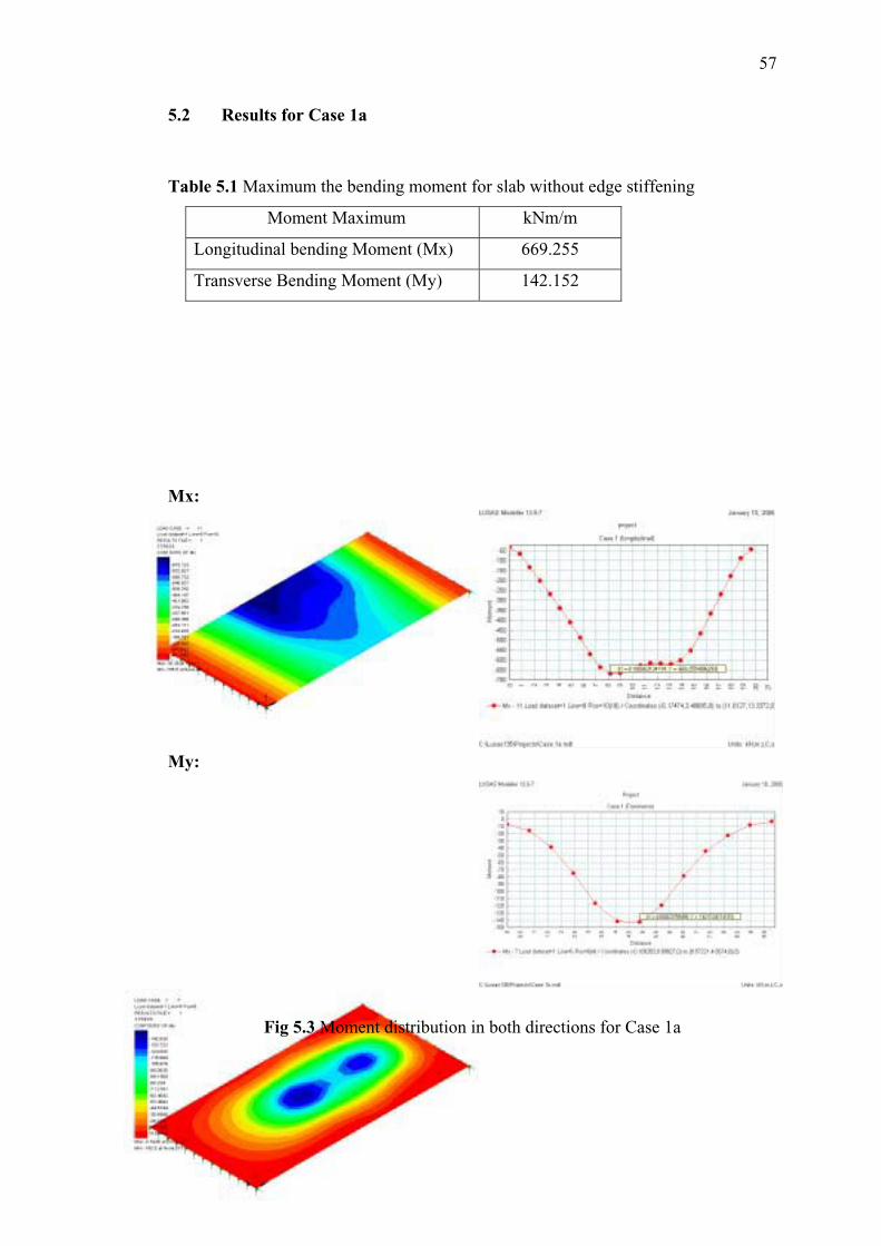
5.2 Results for Case 1a
Table 5.1 Maximum the bending moment for slab without edge stiffening
Moment Maximum kNm/m
Longitudinal bending Moment (Mx) 669.255
Transverse Bending Moment (My) 142.152
Mx:
My:
Fig 5.3 Moment distribution in both directions for Case 1a
58
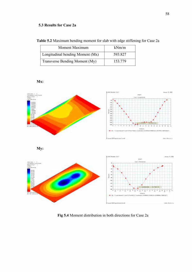
5.3 Results for Case 2a
Table 5.2 Maximum bending moment for slab with edge stiffening for Case 2a
Moment Maximum kNm/m
Longitudinal bending Moment (Mx) 593.827
Transverse Bending Moment (My) 153.779
Mx:
My:
Fig 5.4 Moment distribution in both directions for Case 2a
59
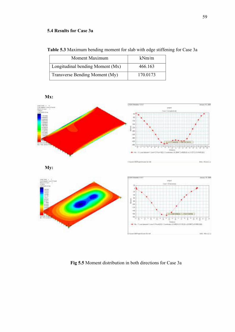
5.4 Results for Case 3a
Table 5.3 Maximum bending moment for slab with edge stiffening for Case 3a
Moment Maximum kNm/m
Longitudinal bending Moment (Mx) 466.163
Transverse Bending Moment (My) 170.0173
Mx:
My:
Fig 5.5 Moment distribution in both directions for Case 3a

CHAPTER VI
DISCUSSION OF RESULTS
6.1 Result of both method
The calculated values of longitudinal and transverse moments are
summarized in Table 6.1 for load distribution method and table 6.2 for finite element
method. In general the presence of edge-stiffening beam resulted in significant
reduction of longitudinal moment but a slight increase of transverse moment. Figure
6.1 and 6.2 shows comparisons of maximum longitudinal bending moment and
transverse bending moment obtains for deck bridge between both case for load
distribution method and finite element method.
Table 6.1 Result of longitudinal and transverse moment with Load Distribution Method
Moment CASE 1 CASE 2 % Difference CASE 3 % Difference % Difference
(kN/m / m-width) (kN/m / m-width) Cas e1-Cas e2 (kN/m / m-width) Cas e1-Cas e3 Cas e2-Cas e3
Longitudinal 754.8255 515.296 31.73 313.0875 58.52 39.24Transverse 178.312 186.7696 4.74 206.6878 15.91 10.66
Table 6.2 Result of longitudinal and transverse moment with Finite Element Method Moment CASE 1 CASE 2 % Difference CASE 3 % Difference % Difference
(kN/m / m-width) (kN/m / m-width) Cas e1-Cas e2 (kN/m / m-width) Cas e1-Cas e3 Cas e2-Cas e3
Longitudinal 669.345 592.619 11.46 465.803 30.41 21.40Transvere 142.512 153.779 7.91 170.0173 19.30 10.56

61
735.6814
515.296
313.0875
0100200300400500600700800
Mom
ent
Comparasion Longitudinal Moment
case 1 Case 2 Case3
178.312186.7696 206.6878
0
50
100
150
200
250
Mom
ent
Comparasion Transverse Moment
case 1 Case 2 Case3
Fig 6.1 shows the comparison between Case 1, 2 and 3 in maximum bending
moment of the longitudinal beams and transverse bending moment for load
distribution method
669.345
592.619465.803
0100200300
400500600700
Mom
ent
Comparasion Longitudinal Moment
case 1 Case 2 Case3
142.512153.779 170.0173
0
50
100
150
200M
omen
t
Comparasion Transverse Moment
case 1 Case 2 Case3
Fig 6.2 shows the comparison between Case 1, 2 and 3 in maximum bending
moment of the longitudinal beams and transverse bending moment for finite element
method
An analysis of a slab bridge with or without edge-stiffening beams is made
and the result obtained from LUSAS programs (Finite Element Method) are
compared with those derived theoretically (Load Distribution Method). Results for
the analysis of longitudinal and transverse moment are obtained from load
distribution method and finite element method. This will allow the assessment be
made on effect of edge-stiffening to both longitudinal and transverse moments.
Comparison between load distribution method and finite element method is show in
figure 6.3.

62
754.83669.345
515.296 592.619
313.0875
465.803
0100
200
300
400
500600
700
800
Mom
ent
Comparasion Longitudinal Moment
case 1 case 2 case 3
178.312142.512
186.7696153.779
206.6878
170.0173
0
50
100
150
200
250
Mom
ent
Comparasion Transverse Moment
case 1 case 2 case 3
Fig 6.3 shows the comparison between load distribution method and finite element
method for Case 1, 2 and 3 in maximum bending moment of the longitudinal beams
and transverse bending moment.

63
6.2 General Effect of Edge-Stiffening
In general the effect of edge-stiffening beam is to reduce the maximum
longitudinal moment and to increase the maximum transverse moment. From Table
6.1 and figure 6.1 it can be seen that the effect of edge-stiffening with a simple
‘upstand’ reduces the longitudinal moment by 31.73% and increases the transverse
moment by 4.74%. For Case 3, with the combination of ‘upstand’ and ‘downstand’,
there is further reduction of longitudinal moment by 58.52% and increase in
transverse moment by 10.66%. Table 6.2 and figure 6.2 are shows that effect edge-
stiffening with a simple ‘upstand’ reduces the longitudinal moment by 11.46% and
increase the transverse moment by 7.91%. By providing an additional ‘downstand’,
further reduction of longitudinal moment by 30.41% and increase the transverse
moment by 19.30%.
6.3 Form of Edge-Stiffening
The different form and size of edge-stiffening will influence of the
longitudinal and transverse moment. In Case 2 with ‘upstand’ (200x600mm)
compared With Case 3 with ‘upstand’ and ’downstand’ (200x1000mm) there is a
reduction in longitudinal moment by 39.2% for load distribution method and 21.4%
for finite element method, while the transverse moment increased by 10.66% for load
distribution method and 10.56% for Finite Element method.
6.4 Method of Analysis
For analysis of deck without edge-stiffening (Case 1), the values of
longitudinal and transverse moments obtained by load distribution method are bigger
that those obtained by finite element method. The difference is about 11.32 % for
longitudinal moment and 20 % for transverse moment. However, for the deck with

64
edge-stiffening (Case 2 and Case 3) the load distribution method given lower values
of longitudinal moment by about 15-48.7 % compared to finite element method. The
inverse is true for the transverse moment, whereby the values given by load
distribution method are higher by 17 %.

CHAPTER VII
CONCLUSIONS
7.1 General Conclusions
1. The general effect of edge-stiffening in bridge deck is to reduce the longitudinal
moment significantly. Although the transverse moment shows an increase, this
however, is less significant. The increase in transverse moment is offset by
advantageous reduction in longitudinal moment. Results from both method show
similar trend.
2. An edge-stiffening beam with a simple ‘upstand’ (200x600mm) reduced the
longitudinal moment by 11.46%-31.73% while the transverse moment increased
by 4.74%-7.91%. By providing an additional ‘downstand’ (200x1000mm),
further reduction of longitudinal moment is achieved by 30.41%-58.52%, which
is very significant. However this also results in significant increase in transverse
moment by 15.91%-19.3%. Although different form and size of edge-stiffening
beam will influence the moment, the choice will be dependent on various factors
such as technical requirement, nature of service to be provided and cost.
3. The effect of edge-stiffening is due to the modifying effects of the edge shear and
edge moment due to the presence of the edge beam.
4. In general, the values of moments obtained by load distribution method are
higher that those obtained by finite element method except for longitudinal
moments in edge-stiffening Case. The load distribution method uses simplified

66
equations of a complex edge shear forces and moment acting at edge beam.
Whereas finite element method is influenced by the quality of modeling, meshing
and choice of element type, material and support conditions.
7.2 Recommendations for future study
To improve the study on the effect edge-stiffening in bridge decks, some
recommendations are proposed to produce more comprehensive finding in future
study.
i. The comparison between different procedures used for other program finite
element such as COSMOS-M, NASTRAN, ABAQUS and ANSYS [5]
ii. Laboratory tests are can be used to carry out and for comparison and
verification with theoretical calculation (load distribution method) or finite
element method.

67
REFERENCE
LITTLE, G. and ROWE, R.E. The effect of edge-stiffening and eccentric
transverse prestress in bridge. London, Cement and Concrete Association, November
1957. Technical Report TRA/279.
ROWE, R.E. Concrete Bridge Design. London, C.R.Brooks Ltd.,1962.
BECKETT, D. An Introduction to Structural Design (1) Concrete Bridge.
Surrey University Press.,1973.
L.A. CLARK. Concrete Bridge Design to BS 5400. Construction Press., 1983
CUSENS, A.R. and PAMA, R.P. Bridge Deck Analysis. A Wiley-
Interscience Publication. 1975.
EDMUND C. HAMBLY. Bridge Deck Behaviour. Chapman and Hall Ltd 11
New Fetter Lane, London EC4P 4EE. 1976.
AZLAN, A.R (2004), Method of Load Distribution Coefficients for Bridge Deck Analysis,
Bridge Engineering Notes, Faculty of Civil Engineering, University Technology
Malaysia.

68
APPENDIX A
69

70

71
APPENDIX B

72

73

74

75

76

77

78

79

80

81

82
APPENDIX C

83

84

85

86

87

88

89
Related Documents