Journal of Engineering Sciences, Assiut University, Vol. 40, No 1, pp.93-108, January 2012 93 BEHAVIOR OF SIMPLY SUPPORTED COMPOSITE CONCRETE-STEEL BEAM WITH CORRUGATED WEB UNDER VERTICAL LOADS Atif M. Abdel Hafez a , M.M. Ahmed a , A.S. Alamary b , A.M. Mohmoud c a Associate Professor of structural Engineering, Assuit University b Associate Professor of structural Engineering, AL-Azhar University. c demonstrator of structural Engineering, AL-Azhar University. (Received October 31, 2011 Accepted November 29, 2011) This paper presents the behavior of simply supported concrete-steel composite beams with corrugated web under vertical loads using the commercial finite element (FE) software ANSYS. The three-dimensional (FE) model is used to simulate the overall flexural and shear behavior of simply supported composite beams with corrugated web subjected to vertical loads. This study covers: load deflection behavior and load strain curve. The reliability of the model is demonstrated by comparison with experimental results test carried out by author and others. Two identical composite beams with corrugated web were tested to failure under vertical loads. The comparison shows good agreement. A parametric study was undertaken using the validated model performed using finite element program. The parametric analysis was executed to study the effect of web thickness on the behavior of concrete-steel composite beam under vertical loads. The comparison between concrete-steel composite beam with corrugated and flat web was introduced in this paper. From this study, it can be concluded that, the corrugation in web increases the stiffness and ductility for composite beam. The increasing of corrugated web thickness increases the ultimate load and enhances the shear behavior of concrete-steel composite beam. KEYWORDS: Experimental tests, finite element analysis, composite beam, corrugated steel web, nonlinear analysis. 1. INTRODUCTION Steel girders have been used for many years; new generation of optimized steel girders was developed by the advances in structural and fabrication technology. One of the developments in structural steel during the past few years has been the availability of corrugated web I-beams. Economical design of steel girders normally requires thin webs. The use of corrugated webs is a possible way of achieving adequate out-of-plane stiffness without using stiffeners. Engineers have long realized that corrugation in webs increases their stability against buckling and can result in economical design. The web corrugation profile can be viewed as uniformly distributed stiffening in the transverse direction of the beam. When girders with corrugated webs are compared with those with stiffened flat webs, it can be found that trapezoidal corrugation in the web enables

Welcome message from author
This document is posted to help you gain knowledge. Please leave a comment to let me know what you think about it! Share it to your friends and learn new things together.
Transcript

Journal of Engineering Sciences, Assiut University, Vol. 40, No 1, pp.93-108, January 2012
93
BEHAVIOR OF SIMPLY SUPPORTED COMPOSITE CONCRETE-STEEL BEAM WITH CORRUGATED
WEB UNDER VERTICAL LOADS
Atif M. Abdel Hafeza, M.M. Ahmeda, A.S. Alamaryb, A.M. Mohmoudc
aAssociate Professor of structural Engineering, Assuit University
bAssociate Professor of structural Engineering, AL-Azhar University.
cdemonstrator of structural Engineering, AL-Azhar University.
(Received October 31, 2011 Accepted November 29, 2011)
This paper presents the behavior of simply supported concrete-steel
composite beams with corrugated web under vertical loads using the
commercial finite element (FE) software ANSYS. The three-dimensional
(FE) model is used to simulate the overall flexural and shear behavior
of simply supported composite beams with corrugated web subjected to
vertical loads. This study covers: load deflection behavior and load
strain curve. The reliability of the model is demonstrated by comparison
with experimental results test carried out by author and others. Two
identical composite beams with corrugated web were tested to failure
under vertical loads. The comparison shows good agreement. A
parametric study was undertaken using the validated model performed
using finite element program. The parametric analysis was executed to
study the effect of web thickness on the behavior of concrete-steel
composite beam under vertical loads. The comparison between
concrete-steel composite beam with corrugated and flat web was
introduced in this paper. From this study, it can be concluded that, the
corrugation in web increases the stiffness and ductility for composite
beam. The increasing of corrugated web thickness increases the
ultimate load and enhances the shear behavior of concrete-steel
composite beam.
KEYWORDS: Experimental tests, finite element analysis, composite
beam, corrugated steel web, nonlinear analysis.
1. INTRODUCTION
Steel girders have been used for many years; new generation of optimized steel girders
was developed by the advances in structural and fabrication technology. One of the
developments in structural steel during the past few years has been the availability of
corrugated web I-beams. Economical design of steel girders normally requires thin
webs. The use of corrugated webs is a possible way of achieving adequate out-of-plane
stiffness without using stiffeners. Engineers have long realized that corrugation in webs
increases their stability against buckling and can result in economical design. The web
corrugation profile can be viewed as uniformly distributed stiffening in the transverse
direction of the beam. When girders with corrugated webs are compared with those
with stiffened flat webs, it can be found that trapezoidal corrugation in the web enables
Atif M. Abdel Hafez, M.M.Ahmed, A.S.Alamary, and A.M.Mohmoud
94
the use of thinner webs without transversal stiffeners which eliminate the cost and time
[1]. Also these beams have 9 to 13% less weight than current traditionally stiffened
girders with flat webs [1]. Several previous studies [2-10] had been concerned on steel
girders with corrugated webs. Most of these were about the shear and bending behavior
of simply supported beams. Composite action between two materials enhances
structural efficiency by combining the structural elements to create a single composite
section. Composite beam designs provide a significant economy through reduced
material, more slender floor depths and faster construction. Moreover, this system is
well recognized in terms of the stiffness and strength improvements that can be
achieved when compared with non-composite solutions. Therefore, the objective of
this research is to study theoretically the influence of web corrugation on the structural
behavior of concrete-steel composite beam under vertical loads. In order to use steel-
concrete composite beam with corrugated web in practice, their behavior under shear
load needs to be investigated. These beams are used in bridges and large span
structures. In order to achieve economical design, the thickness of the web should be as
small as possible. However for thin webs, shear buckling is very likely to happen. For
steel-concrete composite beam with flat web, use of stiffeners in the web or increase
the web thickness is an effective way to increase the shear capacity. By the adoption of
corrugated web, thin web panel can also be used effectively and shear buckling can be
avoided. Corrugated web composite beams offer several advantages over the stiffened
flat web. The corrugations not only provided enhanced shear stability, but they also
eliminate the need for transverse stiffeners, thereby offering the potential for improved
fatigue life.
2. THEORETIACL APPROACH AND FINITE ELEMENT MODELING
It is widely known that laboratory tests require a great amount of time, are very
expensive and, in some cases, can even be impractical. Also it is well known that, the
finite element method becomes, in recent years, a powerful and useful tool for the
analysis of a wide range of engineering problems. A comprehensive finite element
model permits a considerable reduction in the number of experiments. Nevertheless, in
a complete investigation of any structural system, the experimental phase is essential.
Taking into account that numerical models should be based on reliable test results,
experimental and numerical / theoretical analyses complement each other in the
investigation of a particular structural phenomenon. In order to obtain reliable results
up to failure, finite element models must properly represent the constituent parts, adopt
adequate elements and use appropriate solution techniques. As the behavior of
composite beams presents significant nonlinear effects, it is fundamental that the
interaction of all different components should be properly modeled, as well as the
interface behavior. Once suitably validated, the model can be utilized to investigate
aspects of behavior in far more detail than is possible in laboratory work. For instance,
it permits the study of the sensitivity of response to variability of key component
characteristics, including material properties and shear stud layout. The present
investigation focuses on the modeling of concrete-steel composite beams with
corrugated web under vertical loading using the Finite element program ANSYS. A
three dimensional model is proposed, in which all the main structural parameters and
BEHAVIOR OF SIMPLY SUPPORTED COMPOSITE CONCRETE- … 95
associated nonlinearities are included (concrete slab, steel beam and shear connectors).
An eight-node solid element, SOLID65, was used to model the concrete. Each solid
element has eight nodes with three degrees of freedom at each node – translations in
the nodal x, y, and z directions. The element is capable of plastic deformation, cracking
in three orthogonal directions, and crushing.
LINK8 element was used to model the steel reinforcement. Two nodes are
required for this element. Each node has three degrees of freedom, – translations in the
nodal x, y, and z directions. The element is also capable of plastic deformation.
The finite element elastic-plastic shell (SHELL43) was considered for steel
section. The element SHELL43 is defined by four nodes having six degrees of freedom
at each node. The deformation shapes are linear in both in-plane directions. The
element allows for plasticity, creep, stress stiffening, large deflections, and large strain
capabilities.
A nonlinear spring (COMBIN39) was used to represent the shear connectors.
The element COMBIN39 is defined by two node points and a generalized force–deflection curve has longitudinal or tensional capability. The longitudinal option is a
uniaxial tension–compression element with up to three degrees of freedom
(translations) at each node.
In order to avoid numerical problems, the values measured in the experimental
tests for the material properties of the steel components (webs and flanges) are used in
the finite element analyses.
Displacement boundary conditions are needed to constrain the model to get a
unique solution. To ensure that the model acts in the same way as the experimental
beam boundary conditions need to be applied at the supports and loadings exist. The
support was modeled in such a way that a roller was created. A single line of nodes on
the plate were given constraint in the UY, and UZ directions, applied as constant
values of zero. By achievement this, the beam will be allowed to rotate at the support.
The force applied at ten nodes each node on the plate is one tenth of the actual force
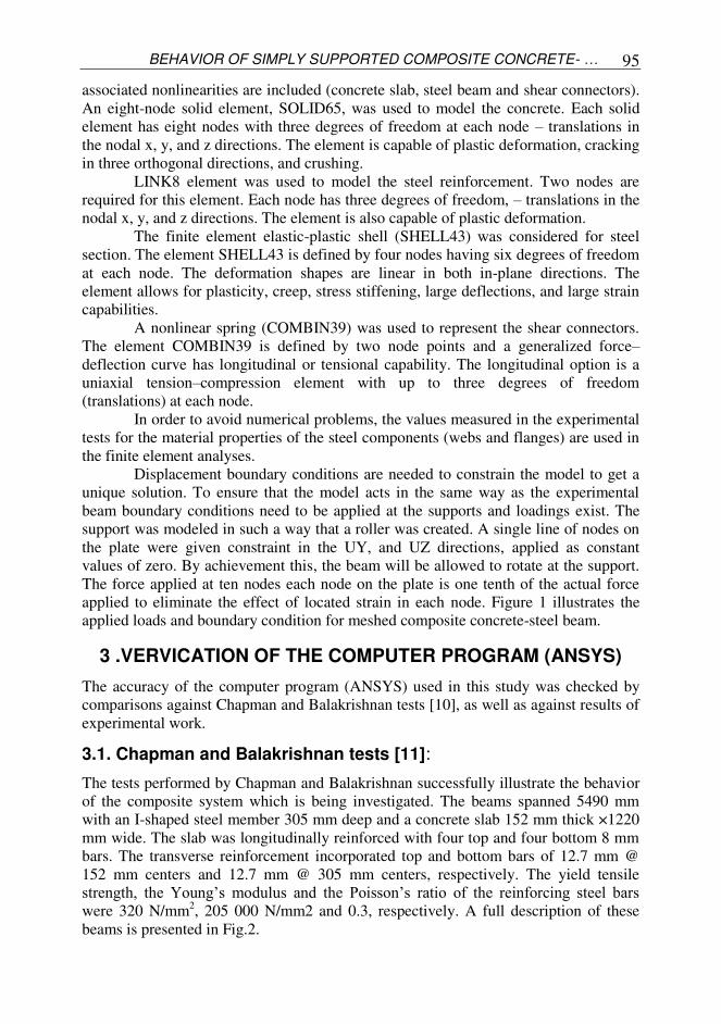
applied to eliminate the effect of located strain in each node. Figure 1 illustrates the
applied loads and boundary condition for meshed composite concrete-steel beam.
3 .VERVICATION OF THE COMPUTER PROGRAM (ANSYS)
The accuracy of the computer program (ANSYS) used in this study was checked by
comparisons against Chapman and Balakrishnan tests [10], as well as against results of
experimental work.
3.1. Chapman and Balakrishnan tests [11]:
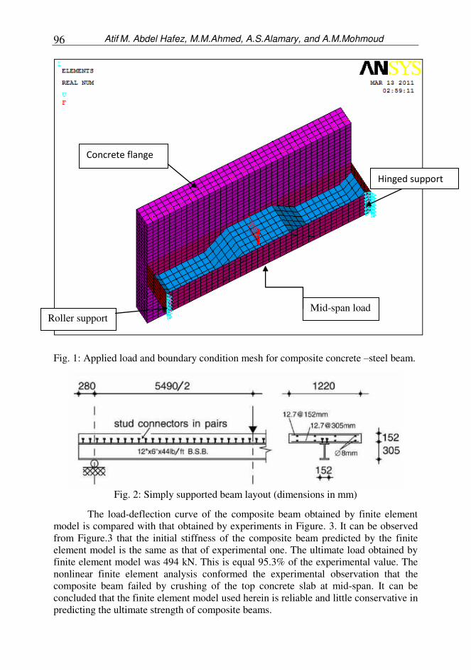
The tests performed by Chapman and Balakrishnan successfully illustrate the behavior
of the composite system which is being investigated. The beams spanned 5490 mm
with an I-shaped steel member 305 mm deep and a concrete slab 152 mm thick ×1220
mm wide. The slab was longitudinally reinforced with four top and four bottom 8 mm
bars. The transverse reinforcement incorporated top and bottom bars of 12.7 mm @
152 mm centers and 12.7 mm @ 305 mm centers, respectively. The yield tensile
strength, the Young’s modulus and the Poisson’s ratio of the reinforcing steel bars were 320 N/mm
2, 205 000 N/mm2 and 0.3, respectively. A full description of these
beams is presented in Fig.2.
Atif M. Abdel Hafez, M.M.Ahmed, A.S.Alamary, and A.M.Mohmoud
96
Fig. 1: Applied load and boundary condition mesh for composite concrete –steel beam.
Fig. 2: Simply supported beam layout (dimensions in mm)
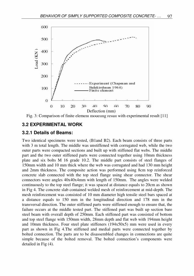
The load-deflection curve of the composite beam obtained by finite element
model is compared with that obtained by experiments in Figure. 3. It can be observed
from Figure.3 that the initial stiffness of the composite beam predicted by the finite
element model is the same as that of experimental one. The ultimate load obtained by
finite element model was 494 kN. This is equal 95.3% of the experimental value. The
nonlinear finite element analysis conformed the experimental observation that the
composite beam failed by crushing of the top concrete slab at mid-span. It can be
concluded that the finite element model used herein is reliable and little conservative in
predicting the ultimate strength of composite beams.
Roller support Mid-span load
Concrete flange
Hinged support
BEHAVIOR OF SIMPLY SUPPORTED COMPOSITE CONCRETE- … 97
Fig. 3: Comparison of finite element modeling result with experimental result [11]
3.2 EXPERIMENTAL WORK
3.2.1 Details of Beams:
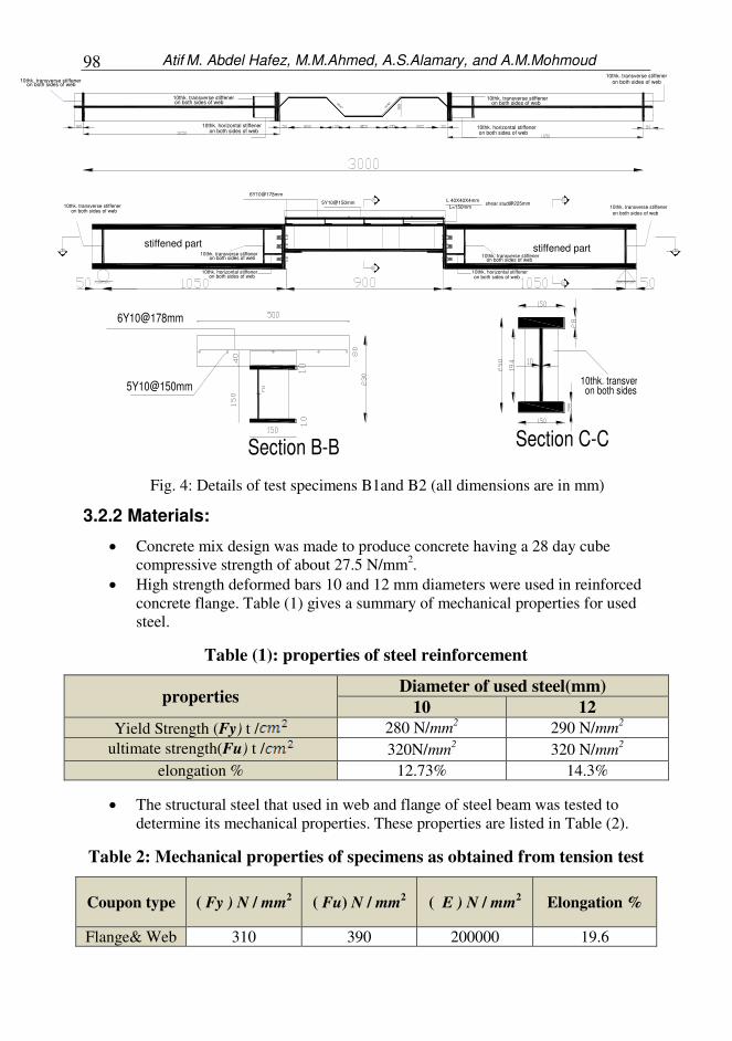
Two identical specimens were tested, (B1and B2). Each beam consists of three parts
with 3 m total length. The middle was unstiffened with corrugated web, while the two
outer parts were compacted sections and built up with stiffened flat webs. The middle
part and the two outer stiffened parts were connected together using 10mm thickness
plate and six bolts M 16 grade 10.2. The middle part consists of steel flanges of
150mm width and 10 mm thick where the web was corrugated and had 130 mm height
and 2mm thickness. The composite action was performed using 8cm top reinforced
concrete slab connected with the top steel flange using shear connector. The shear
connectors were angles 40x40x4mm with length of 150mm. The angles were welded
continuously to the top steel flange; it was spaced at distance equals to 20cm as shown
in Fig 4. The concrete slab contained welded mesh of reinforcement at mid-depth. The
mesh reinforcement was consisted of 10 mm diameter high tensile steel bars spaced at
a distance equals to 150 mm in the longitudinal direction and 178 mm in the
transversal direction. The outer stiffened parts were stiffened enough to ensure that, the
failure occurs at the middle tested part. The stiffened part was built up section bare
steel beam with overall depth of 250mm. Each stiffened part was consisted of bottom
and top steel flange with 150mm width, 28mm depth and flat web with 194mm height
and 10mm thickness. Four steel plate stiffeners (194x50x5) mm were used in every
part as shown in Fig 4.The stiffened and medial parts were connected together by
bolted connection. The parts are to be disassembled changes in connections are quite
simple because of the bolted removal. The bolted connection’s components were
detailed in Fig (4).
Deflection (mm)
Lo
ad (
KN
)
Atif M. Abdel Hafez, M.M.Ahmed, A.S.Alamary, and A.M.Mohmoud
98
3.2.2 Materials:
Concrete mix design was made to produce concrete having a 28 day cube
compressive strength of about 27.5 N/mm2.
High strength deformed bars 10 and 12 mm diameters were used in reinforced
concrete flange. Table (1) gives a summary of mechanical properties for used
steel.
Table (1): properties of steel reinforcement
properties Diameter of used steel(mm)
10 12
Yield Strength (Fy) t / 280 N/mm2
290 N/mm2
ultimate strength(Fu) t / 320N/mm2 320 N/mm
2
elongation % 12.73% 14.3%
The structural steel that used in web and flange of steel beam was tested to
determine its mechanical properties. These properties are listed in Table (2).
Table 2: Mechanical properties of specimens as obtained from tension test
Coupon type ( Fy ) N / mm2
( Fu) N / mm2 ( E ) N / mm
2 Elongation %
Flange& Web 310 390 200000 19.6
stiffened part stiffened part
10thk. transverse stiffener
10thk. transverse stiffener10thk. transverse stiffener
10thk. transverse stiffener
10thk. horizontal stiffeneron both sides of web
6Y10@178mm L 40X40X4mm
L=150mm shear stud@225mm
10thk. horizontal stiffeneron both sides of web
on both sides of web
on both sides of web
on both sides of web
on both sides of web
5Y10@150mm
10thk. transverse stiffeneron both sides of web
10thk. horizontal stiffeneron both sides of web
10thk. transverse stiffeneron both sides of web
10thk. horizontal stiffeneron both sides of web
10thk. transverse stiffeneron both sides of web
10thk. transverse stiffeneron both sides of web
6Y10@178mm
5Y10@150mm
Section B-B
10thk. transverse stion both sides
Section C-C
Fig. 4: Details of test specimens B1and B2 (all dimensions are in mm)
BEHAVIOR OF SIMPLY SUPPORTED COMPOSITE CONCRETE- … 99
3.2.3 Test procedure and Instrumentation:
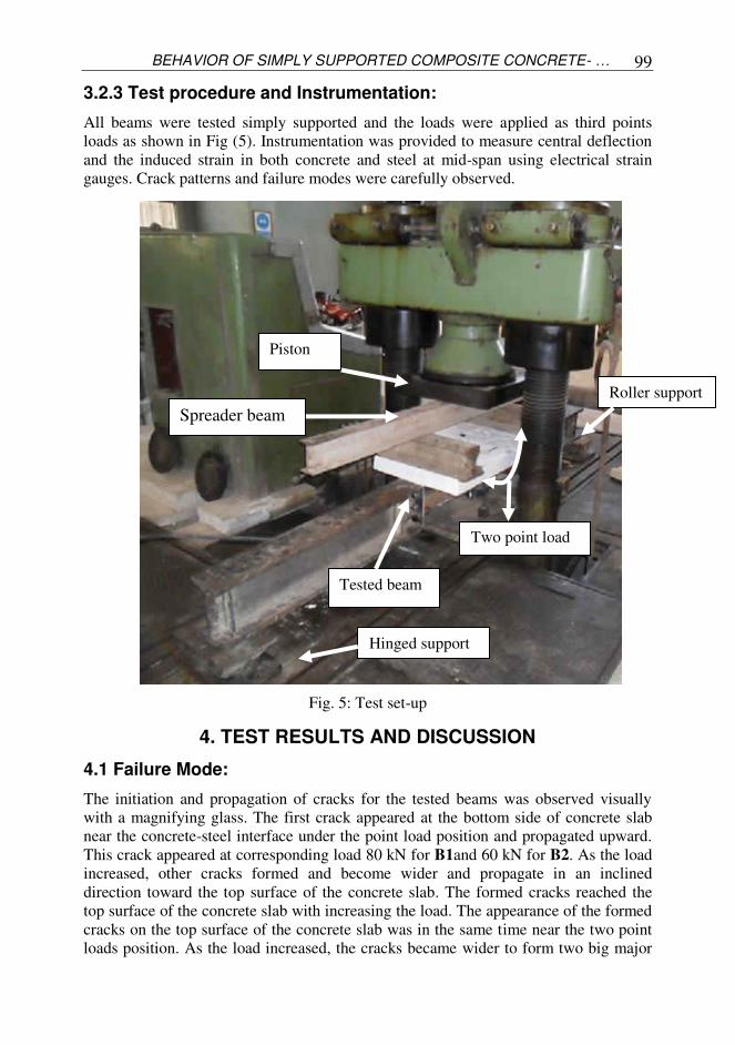
All beams were tested simply supported and the loads were applied as third points
loads as shown in Fig (5). Instrumentation was provided to measure central deflection
and the induced strain in both concrete and steel at mid-span using electrical strain
gauges. Crack patterns and failure modes were carefully observed.
Fig. 5: Test set-up
4. TEST RESULTS AND DISCUSSION
4.1 Failure Mode:
The initiation and propagation of cracks for the tested beams was observed visually
with a magnifying glass. The first crack appeared at the bottom side of concrete slab
near the concrete-steel interface under the point load position and propagated upward.
This crack appeared at corresponding load 80 kN for B1and 60 kN for B2. As the load
increased, other cracks formed and become wider and propagate in an inclined
direction toward the top surface of the concrete slab. The formed cracks reached the
top surface of the concrete slab with increasing the load. The appearance of the formed
cracks on the top surface of the concrete slab was in the same time near the two point
loads position. As the load increased, the cracks became wider to form two big major
Tested beam
Hinged support
Roller support
Two point load
Piston
Spreader beam
Atif M. Abdel Hafez, M.M.Ahmed, A.S.Alamary, and A.M.Mohmoud
100
cracks at each side of the concrete slab. The propagation of the major cracks was
toward the mid span and inclined with approximately 30 º on the longitudinal center
line of the concrete-steel composite beam. New minor cracks were observed with
increasing the load. The new formed cracks were neighbor and parallel to the major
cracks. The minor cracks were appeared at corresponding load equal to 120 kN for B1
and 100 kN for B2.Then the propagation of cracks stilled in the same manner with
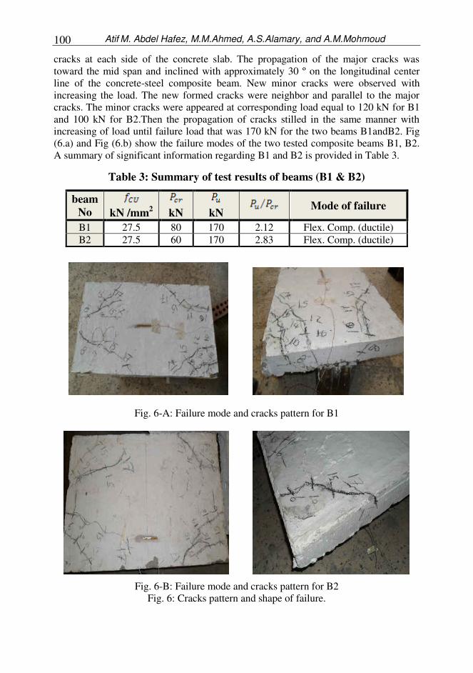
increasing of load until failure load that was 170 kN for the two beams B1andB2. Fig
(6.a) and Fig (6.b) show the failure modes of the two tested composite beams B1, B2.
A summary of significant information regarding B1 and B2 is provided in Table 3.
Table 3: Summary of test results of beams (B1 & B2)
Mode of failure
kN
kN
kN /mm2
beam
No
Flex. Comp. (ductile) 2.12 170 80 27.5 B1
Flex. Comp. (ductile) 2.83 170 60 27.5 B2
Fig. 6-A: Failure mode and cracks pattern for B1
Fig. 6-B: Failure mode and cracks pattern for B2
Fig. 6: Cracks pattern and shape of failure.
BEHAVIOR OF SIMPLY SUPPORTED COMPOSITE CONCRETE- … 101
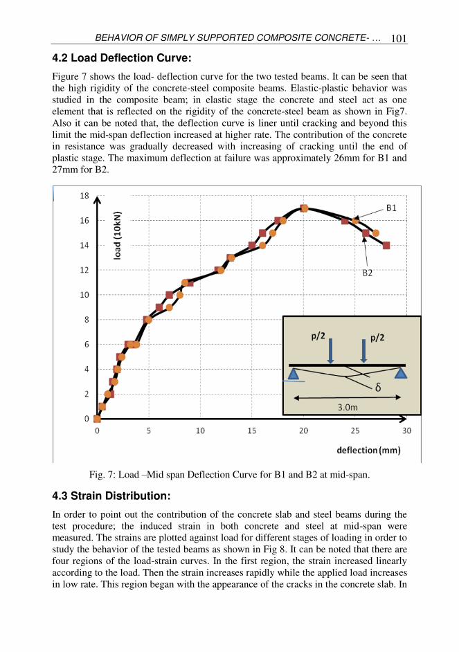
4.2 Load Deflection Curve:
Figure 7 shows the load- deflection curve for the two tested beams. It can be seen that
the high rigidity of the concrete-steel composite beams. Elastic-plastic behavior was
studied in the composite beam; in elastic stage the concrete and steel act as one
element that is reflected on the rigidity of the concrete-steel beam as shown in Fig7.
Also it can be noted that, the deflection curve is liner until cracking and beyond this
limit the mid-span deflection increased at higher rate. The contribution of the concrete
in resistance was gradually decreased with increasing of cracking until the end of
plastic stage. The maximum deflection at failure was approximately 26mm for B1 and
27mm for B2.
Fig. 7: Load –Mid span Deflection Curve for B1 and B2 at mid-span.
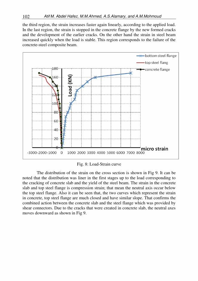
4.3 Strain Distribution:
In order to point out the contribution of the concrete slab and steel beams during the
test procedure; the induced strain in both concrete and steel at mid-span were
measured. The strains are plotted against load for different stages of loading in order to
study the behavior of the tested beams as shown in Fig 8. It can be noted that there are
four regions of the load-strain curves. In the first region, the strain increased linearly
according to the load. Then the strain increases rapidly while the applied load increases
in low rate. This region began with the appearance of the cracks in the concrete slab. In
Atif M. Abdel Hafez, M.M.Ahmed, A.S.Alamary, and A.M.Mohmoud
102
the third region, the strain increases faster again linearly, according to the applied load.
In the last region, the strain is stopped in the concrete flange by the new formed cracks
and the development of the earlier cracks. On the other hand the strain in steel beam
increased quickly when the load is stable. This region corresponds to the failure of the
concrete-steel composite beam.
Fig. 8: Load-Strain curve
The distribution of the strain on the cross section is shown in Fig 9. It can be
noted that the distribution was liner in the first stages up to the load corresponding to
the cracking of concrete slab and the yield of the steel beam. The strain in the concrete
slab and top steel flange is compression strain; that mean the neutral axis occur below
the top steel flange. Also it can be seen that, the two curves which represent the strain
in concrete, top steel flange are much closed and have similar slope. That confirms the
combined action between the concrete slab and the steel flange which was provided by
shear connectors. Due to the cracks that were created in concrete slab, the neutral axes
moves downward as shown in Fig 9.
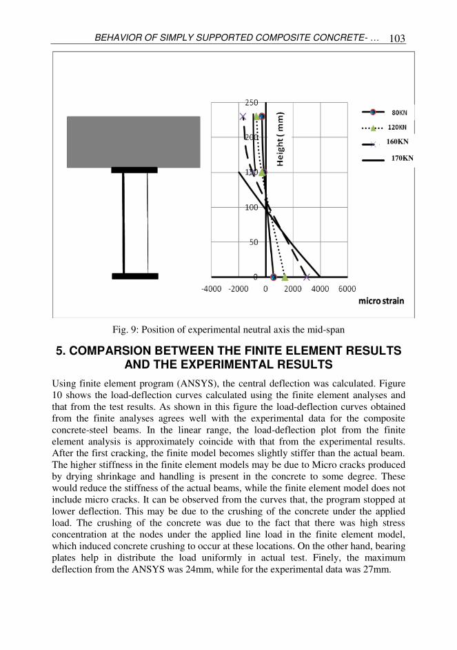
BEHAVIOR OF SIMPLY SUPPORTED COMPOSITE CONCRETE- … 103
Fig. 9: Position of experimental neutral axis the mid-span
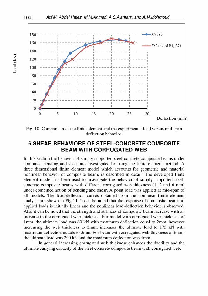
5. COMPARSION BETWEEN THE FINITE ELEMENT RESULTS AND THE EXPERIMENTAL RESULTS
Using finite element program (ANSYS), the central deflection was calculated. Figure
10 shows the load-deflection curves calculated using the finite element analyses and
that from the test results. As shown in this figure the load-deflection curves obtained
from the finite analyses agrees well with the experimental data for the composite
concrete-steel beams. In the linear range, the load-deflection plot from the finite
element analysis is approximately coincide with that from the experimental results.
After the first cracking, the finite model becomes slightly stiffer than the actual beam.
The higher stiffness in the finite element models may be due to Micro cracks produced
by drying shrinkage and handling is present in the concrete to some degree. These
would reduce the stiffness of the actual beams, while the finite element model does not
include micro cracks. It can be observed from the curves that, the program stopped at
lower deflection. This may be due to the crushing of the concrete under the applied
load. The crushing of the concrete was due to the fact that there was high stress
concentration at the nodes under the applied line load in the finite element model,
which induced concrete crushing to occur at these locations. On the other hand, bearing
plates help in distribute the load uniformly in actual test. Finely, the maximum
deflection from the ANSYS was 24mm, while for the experimental data was 27mm.
160KN
170KN
Atif M. Abdel Hafez, M.M.Ahmed, A.S.Alamary, and A.M.Mohmoud
104
Fig. 10: Comparison of the finite element and the experimental load versus mid-span
deflection behavior.
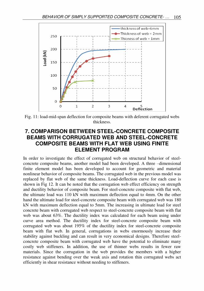
6 SHEAR BEHAVIORE OF STEEL-CONCRETE COMPOSITE BEAM WITH CORRUGATED WEB
In this section the behavior of simply supported steel-concrete composite beams under
combined bending and shear are investigated by using the finite element method. A
three dimensional finite element model which accounts for geometric and material
nonlinear behavior of composite beam, is described in detail. The developed finite
element model has been used to investigate the behavior of simply supported steel-
concrete composite beams with different corrugated web thickness (1, 2 and 6 mm)
under combined action of bending and shear. A point load was applied at mid-span of
all models. The load-deflection curves obtained from the nonlinear finite element
analysis are shown in Fig 11. It can be noted that the response of composite beams to
applied loads is initially linear and the nonlinear load-deflection behavior is observed.
Also it can be noted that the strength and stiffness of composite beam increase with an
increase in the corrugated web thickness. For model with corrugated web thickness of
1mm, the ultimate load was 80 kN with maximum deflection equal to 2mm. however
increasing the web thickness to 2mm, increases the ultimate load to 175 kN with
maximum deflection equals to 3mm. For beam with corrugated web thickness of 6mm,
the ultimate load was 200 kN and the maximum deflection was 4mm.
In general increasing corrugated web thickness enhances the ductility and the
ultimate carrying capacity of the steel-concrete composite beam with corrugated web.
Deflection (mm)
Lo
ad (
kN
)
BEHAVIOR OF SIMPLY SUPPORTED COMPOSITE CONCRETE- … 105
Fig. 11: load-mid-span deflection for composite beams with deferent corrugated webs
thickness.
7. COMPARISON BETWEEN STEEL-CONCRETE COMPOSITE BEAMS WITH CORRUGATED WEB AND STEEL-CONCRETE
COMPOSITE BEAMS WITH FLAT WEB USING FINITE ELEMENT PROGRAM
In order to investigate the effect of corrugated web on structural behavior of steel-
concrete composite beams, another model had been developed. A three –dimensional
finite element model has been developed to account for geometric and material
nonlinear behavior of composite beams. The corrugated web in the previous model was
replaced by flat web of the same thickness. Load-deflection curve for each case is
shown in Fig 12. It can be noted that the corrugation web effect efficiency on strength
and ductility behavior of composite beam. For steel-concrete composite with flat web,
the ultimate load was 110 kN with maximum deflection equal to 4mm. On the other
hand the ultimate load for steel-concrete composite beam with corrugated web was 180
kN with maximum deflection equal to 5mm. The increasing in ultimate load for steel
concrete beam with corrugated web respect to steel-concrete composite beam with flat
web was about 63%. The ductility index was calculated for each beam using under
curve area method. The ductility index for steel-concrete composite beam with
corrugated web was about 195% of the ductility index for steel-concrete composite
beam with flat web. In general, corrugations in webs enormously increase their
stability against buckling and can result in very economical designs. Therefore steel-
concrete composite beam with corrugated web have the potential to eliminate many
costly web stiffeners. In addition, the use of thinner webs results in fewer raw
materials. Since the corrugation in the web provides the members with a higher
resistance against bending over the weak axis and rotation thin corrugated webs act
efficiently in shear resistance without needing to stiffeners.

Atif M. Abdel Hafez, M.M.Ahmed, A.S.Alamary, and A.M.Mohmoud
106
Fig. 12: Load-mid-span Deflection for Composite Beams with Corrugated web & Flat
web.
CONCLUSIONS
Based on the results of theoretical and experimental studies on behavior of simply
supported composite concrete-steel beam with corrugated web under vertical loads the
following conclusions are made.
1. The FEA throw Ansys program can be used as a very useful tool in predicting
the failure load of composite concrete-steel beams with corrugated web and
can provide very detailed information for the distribution of stress / strain in
composite beams with corrugated web.
2. The thickness of corrugated web has a very little effect on flexural behavior for
composite concrete-steel beam with corrugated web.
3. There was clear increasing in ductility and ultimate load where corrugations in
webs enormously increase their stability against buckling and can result in
very economical designs.
4. The increasing in ultimate load for steel concrete beam with corrugated web
respect to steel-concrete composite beam with flat web was about 63%.
5. Increasing of corrugated web thickness enhances the shear behavior of steel-
concrete composite beam with corrugated web, increasing the ultimate load
and maximum deflection.
Deflection (mm)
Loa
d (
KN
)
BEHAVIOR OF SIMPLY SUPPORTED COMPOSITE CONCRETE- … 107
REFRENCES
1. Hamada, M., Nakayama, K., Kakihara, M., Saloh, K. and Ohtake, F.,
“Development of welded I-beam with corrugated web,” The Sumitomo Search, No. 29, pp 75-90, 1984.
2. Easley, J. T., “Buckling formulas for corrugated metal shear diaphragms”, Journal of the Structural Division, ASCE, St. 7, pp. 1403-1417, 1975.
3. Easley, J. and McFarland, D., “Buckling of Light – Gage Corrugated Shear
Diaphragms”, Journal of the Structural Division”. ASCE, Vol. 95 No. ST 7, pp.1497–1516, July 1969.S
4. Hlavacek, V., “Shear Instability of Orthotropic Panels,” Acta Technica CSAV, Prague Czechoslovakia, No. 1, 1968.
5. Smith, D. “Behavior of corrugated plates subjected to shear.” MSc thesis, Dept. of Cive Engr. Univ. of Maine, Orono, Maine, 1992.
6. Hamilton. R., "Behavior of Welded Girders with Corrugated Webs", areport
submitted to NSF. August 1993.
7. Elgaaly, M., "Shear Strength of Beams with Corrugated Webs," American Society
of Civil Engineers, Structural Journal, April 1996.
8. Lou, R. & Edlund, B., “Numerical simulation of shear tests on plate girders with
trapezoidally corrugated webs”, Division of Steel and Timber Structures, Chalmers University of Technology, Sweden, 1995
9. Elgaaly, M.,"Bending Strength of Beams with Corrugated Webs," American
Society of Civil Engineers, Structural Journal, June 1997.
10. El-Amin, F.M., Abdelkhalek, M.F., Ahmed,M.M. and Gad, S.R. (2008).
“Nonlinear Behavior of Cantilever Girders with Corrugated steel Webs” Journal of engineering sciences, JES, Assiut University, vol.36, no.6, November, pp. 1319-
1338.
11. Chapman JC, Balakrishnan S. Experiments on composite beams. The Structural
Engineer 1964;42(11):369–83.
Atif M. Abdel Hafez, M.M.Ahmed, A.S.Alamary, and A.M.Mohmoud
108
معرجة تحت تأثير بة من صلب وخرسانة ذات ااعصاب ا مر مرات ا ااحمال سلوك ارأسية ا
مر مرات ا سلوك ا ظرية ي دراسة عملية و بحث ا معرجة يهدف ا ة ذات ااعصاب ا بة من صلب وخرساهيار. رأسية حتي حدوث اا تحت تأثير ااحمال ا
ظريه تمت مازج دراسة بعمل اخطي ا تحليل ثاثي اابعاد ا محدد وباستخدام ا اصر ا ع مرتين بطريقة امرات. تلك ا حمل ااقصي تحديد ا محددة اصر ا ع سبطريقة ا هذ حيث تم دراسة ا قصي ائي وا ح لوك اا
برامج حصول عليها من ا تي تم ا تائج بتلك ا مستخدم بمقارة ا برامج ا تحقق من فاعلية ا مرات . وتم ا اهيار. معمل حتي اا فس اابعاد في ا مرتين ب عملي حيث تم اختبار برامج ودرحة ا وبااعتماد علي فاعلية ا
ه تم دراسة ت مقبو دقة ا قصا مرات في ا عصب علي سلوك ا مرات أثير سمك ا ك اجراء مقارة بين ا ذ وك تحت تأثير ااحمال مسطحه وذ معرجة وتلك ذات ااعصاب ا ة ذات ااعصاب ا بة من صلب وخرسا مر ا
رأسية ا
بحث مايلي:. تي تم استنباطها من ا نتائج ا ومن اهم ا
سلو - ه تأثير ضعيف علي ا عصب ةسمك ا بة من صلب وخرسا مر مرات ا ل ائي ح ك ااه بزيادة - قص. حيث ا ة في ا بة من صلب وخرسا مر مرات ا ه تأثير ملحوظ علي سلوك ا عصب سمك ا
مر. هيار ا ازم ا حمل ااقصي ا عصب يزداد ا سمك احمل ااقصي - سبة ا ظريا و حصول عليها عمليا و تي تم ا تائج ا مرات بمقارة ا ذي تتحمله هذ ا عملي ا ا
ها اتزيد عن برامج وجدت ا حصول عليه من ا ذي تم ا حمل ااقصي ا ي ا مائه. 2.1ا بامثل هذ - اخطي سلوك ا دراسة ا ظري برامج ا ن استخدام ا ة يم مرات بدرجة دقه مقبو تحت تأثير ا
مرات ذي تتحمله هذ ا حمل ااقصي ا تي قد تؤثر علي قيمة ا متغيرات ا دراسة ا ك ذ رأسية و ااحمال اتعرج. ل ا تعرج وش تعرج وزاوية ا عصب وعرض ا ة وسمك ا خرسا مثل مقاومة ا
Related Documents