On the Optimal Control of Switch-Mode DC-DC Converters Tobias Geyer, Georgios Papafotiou, and Manfred Morari Automatic Control Laboratory, Swiss Federal Institute of Technology (ETH) CH-8092 Zurich, Switzerland, {geyer,papafotiou,morari}@control.ee.ethz.ch Abstract. This paper presents a new solution approach to the optimal control problem of fixed frequency switch-mode DC-DC converters using hybrid systems methodologies. In particular, the notion of the N -step model is introduced to capture the hybrid nature of these systems, and an optimal control problem is formulated and solved online, which allows one to easily incorporate in the controller design safety constraints such as current limiting. Simulation results are provided that demonstrate the prospect of this approach. Keywords: Power Electronics, DC-DC Converters, Model Predictive Control, Hybrid Systems 1 Introduction Switch-mode DC-DC converters are power electronic circuits that are used in a large variety of applications due to their light weight, compact size and high efficiency and reliability. They constitute the enabling technology in computer power supplies, battery chargers, sensitive and demanding aerospace and medical applications, and variable speed DC motor drives. Their analysis and design both in the open and the closed loop have at- tracted a wide research interest, and the quest for efficient control techniques is of interest for both the research and the industrial community. Because the DC voltage at the input is unregulated (consider for example the result of an AC rectification) and the output power demand changes significantly over time con- stituting a time-varying load, the scope is to achieve output voltage regulation in the presence of input voltage and output load variations. The difficulties in controlling DC-DC converters arise from their hybrid nature. In general, these converters feature three different modes of operation, where each mode has an associated linear continuous-time dynamic. Furthermore, constraints are present which result from the converter topology. In particular, the manipulated vari- able (duty cycle) is bounded between zero and one, and in the discontinuous current mode a state (inductor current) is constrained to be nonnegative. Ad- ditional constraints are imposed as safety measures, such as current limiting or soft-starting, where the latter constitutes a constraint on the maximal derivative of the current during start-up. The control problem is further complicated by R. Alur and G.J. Pappas (Eds.): HSCC 2004, LNCS 2993, pp. 342–356, 2004. c Springer-Verlag Berlin Heidelberg 2004

Welcome message from author
This document is posted to help you gain knowledge. Please leave a comment to let me know what you think about it! Share it to your friends and learn new things together.
Transcript
On the Optimal Control ofSwitch-Mode DC-DC Converters
Tobias Geyer, Georgios Papafotiou, and Manfred Morari
Automatic Control Laboratory, Swiss Federal Institute of Technology (ETH)CH-8092 Zurich, Switzerland,
{geyer,papafotiou,morari}@control.ee.ethz.ch
Abstract. This paper presents a new solution approach to the optimalcontrol problem of fixed frequency switch-mode DC-DC converters usinghybrid systems methodologies. In particular, the notion of the N -stepmodel is introduced to capture the hybrid nature of these systems, andan optimal control problem is formulated and solved online, which allowsone to easily incorporate in the controller design safety constraints suchas current limiting. Simulation results are provided that demonstratethe prospect of this approach.
Keywords: Power Electronics, DC-DC Converters, Model PredictiveControl, Hybrid Systems
1 Introduction
Switch-mode DC-DC converters are power electronic circuits that are used ina large variety of applications due to their light weight, compact size and highefficiency and reliability. They constitute the enabling technology in computerpower supplies, battery chargers, sensitive and demanding aerospace and medicalapplications, and variable speed DC motor drives.
Their analysis and design both in the open and the closed loop have at-tracted a wide research interest, and the quest for efficient control techniques isof interest for both the research and the industrial community. Because the DCvoltage at the input is unregulated (consider for example the result of an ACrectification) and the output power demand changes significantly over time con-stituting a time-varying load, the scope is to achieve output voltage regulationin the presence of input voltage and output load variations. The difficulties incontrolling DC-DC converters arise from their hybrid nature. In general, theseconverters feature three different modes of operation, where each mode has anassociated linear continuous-time dynamic. Furthermore, constraints are presentwhich result from the converter topology. In particular, the manipulated vari-able (duty cycle) is bounded between zero and one, and in the discontinuouscurrent mode a state (inductor current) is constrained to be nonnegative. Ad-ditional constraints are imposed as safety measures, such as current limiting orsoft-starting, where the latter constitutes a constraint on the maximal derivativeof the current during start-up. The control problem is further complicated by
R. Alur and G.J. Pappas (Eds.): HSCC 2004, LNCS 2993, pp. 342–356, 2004.c© Springer-Verlag Berlin Heidelberg 2004
Verwendete Distiller 5.0.x Joboptions
Dieser Report wurde automatisch mit Hilfe der Adobe Acrobat Distiller Erweiterung "Distiller Secrets v1.0.5" der IMPRESSED GmbH erstellt. Sie koennen diese Startup-Datei für die Distiller Versionen 4.0.5 und 5.0.x kostenlos unter http://www.impressed.de herunterladen. ALLGEMEIN ---------------------------------------- Dateioptionen: Kompatibilität: PDF 1.3 Für schnelle Web-Anzeige optimieren: Nein Piktogramme einbetten: Nein Seiten automatisch drehen: Nein Seiten von: 1 Seiten bis: Alle Seiten Bund: Links Auflösung: [ 2400 2400 ] dpi Papierformat: [ 594.962 841.96 ] Punkt KOMPRIMIERUNG ---------------------------------------- Farbbilder: Downsampling: Ja Berechnungsmethode: Bikubische Neuberechnung Downsample-Auflösung: 300 dpi Downsampling für Bilder über: 450 dpi Komprimieren: Ja Automatische Bestimmung der Komprimierungsart: Ja JPEG-Qualität: Maximal Bitanzahl pro Pixel: Wie Original Bit Graustufenbilder: Downsampling: Ja Berechnungsmethode: Bikubische Neuberechnung Downsample-Auflösung: 300 dpi Downsampling für Bilder über: 450 dpi Komprimieren: Ja Automatische Bestimmung der Komprimierungsart: Ja JPEG-Qualität: Maximal Bitanzahl pro Pixel: Wie Original Bit Schwarzweiß-Bilder: Downsampling: Ja Berechnungsmethode: Bikubische Neuberechnung Downsample-Auflösung: 2400 dpi Downsampling für Bilder über: 3600 dpi Komprimieren: Ja Komprimierungsart: CCITT CCITT-Gruppe: 4 Graustufen glätten: Nein Text und Vektorgrafiken komprimieren: Ja SCHRIFTEN ---------------------------------------- Alle Schriften einbetten: Ja Untergruppen aller eingebetteten Schriften: Nein Wenn Einbetten fehlschlägt: Abbrechen Einbetten: Immer einbetten: [ /Courier-BoldOblique /Helvetica-BoldOblique /Courier /Helvetica-Bold /Times-Bold /Courier-Bold /Helvetica /Times-BoldItalic /Times-Roman /ZapfDingbats /Times-Italic /Helvetica-Oblique /Courier-Oblique /Symbol ] Nie einbetten: [ ] FARBE(N) ---------------------------------------- Farbmanagement: Farbumrechnungsmethode: Farbe nicht ändern Methode: Standard Geräteabhängige Daten: Einstellungen für Überdrucken beibehalten: Ja Unterfarbreduktion und Schwarzaufbau beibehalten: Ja Transferfunktionen: Anwenden Rastereinstellungen beibehalten: Ja ERWEITERT ---------------------------------------- Optionen: Prolog/Epilog verwenden: Ja PostScript-Datei darf Einstellungen überschreiben: Ja Level 2 copypage-Semantik beibehalten: Ja Portable Job Ticket in PDF-Datei speichern: Nein Illustrator-Überdruckmodus: Ja Farbverläufe zu weichen Nuancen konvertieren: Ja ASCII-Format: Nein Document Structuring Conventions (DSC): DSC-Kommentare verarbeiten: Ja DSC-Warnungen protokollieren: Nein Für EPS-Dateien Seitengröße ändern und Grafiken zentrieren: Ja EPS-Info von DSC beibehalten: Ja OPI-Kommentare beibehalten: Nein Dokumentinfo von DSC beibehalten: Ja ANDERE ---------------------------------------- Distiller-Kern Version: 5000 ZIP-Komprimierung verwenden: Ja Optimierungen deaktivieren: Nein Bildspeicher: 524288 Byte Farbbilder glätten: Nein Graustufenbilder glätten: Nein Bilder (< 257 Farben) in indizierten Farbraum konvertieren: Ja sRGB ICC-Profil: sRGB IEC61966-2.1 ENDE DES REPORTS ---------------------------------------- IMPRESSED GmbH Bahrenfelder Chaussee 49 22761 Hamburg, Germany Tel. +49 40 897189-0 Fax +49 40 897189-71 Email: [email protected] Web: www.impressed.de
Adobe Acrobat Distiller 5.0.x Joboption Datei
<< /ColorSettingsFile () /AntiAliasMonoImages false /CannotEmbedFontPolicy /Error /ParseDSCComments true /DoThumbnails false /CompressPages true /CalRGBProfile (sRGB IEC61966-2.1) /MaxSubsetPct 100 /EncodeColorImages true /GrayImageFilter /DCTEncode /Optimize false /ParseDSCCommentsForDocInfo true /EmitDSCWarnings false /CalGrayProfile () /NeverEmbed [ ] /GrayImageDownsampleThreshold 1.5 /UsePrologue true /GrayImageDict << /QFactor 0.9 /Blend 1 /HSamples [ 2 1 1 2 ] /VSamples [ 2 1 1 2 ] >> /AutoFilterColorImages true /sRGBProfile (sRGB IEC61966-2.1) /ColorImageDepth -1 /PreserveOverprintSettings true /AutoRotatePages /None /UCRandBGInfo /Preserve /EmbedAllFonts true /CompatibilityLevel 1.3 /StartPage 1 /AntiAliasColorImages false /CreateJobTicket false /ConvertImagesToIndexed true /ColorImageDownsampleType /Bicubic /ColorImageDownsampleThreshold 1.5 /MonoImageDownsampleType /Bicubic /DetectBlends true /GrayImageDownsampleType /Bicubic /PreserveEPSInfo true /GrayACSImageDict << /VSamples [ 1 1 1 1 ] /QFactor 0.15 /Blend 1 /HSamples [ 1 1 1 1 ] /ColorTransform 1 >> /ColorACSImageDict << /VSamples [ 1 1 1 1 ] /QFactor 0.15 /Blend 1 /HSamples [ 1 1 1 1 ] /ColorTransform 1 >> /PreserveCopyPage true /EncodeMonoImages true /ColorConversionStrategy /LeaveColorUnchanged /PreserveOPIComments false /AntiAliasGrayImages false /GrayImageDepth -1 /ColorImageResolution 300 /EndPage -1 /AutoPositionEPSFiles true /MonoImageDepth -1 /TransferFunctionInfo /Apply /EncodeGrayImages true /DownsampleGrayImages true /DownsampleMonoImages true /DownsampleColorImages true /MonoImageDownsampleThreshold 1.5 /MonoImageDict << /K -1 >> /Binding /Left /CalCMYKProfile (U.S. Web Coated (SWOP) v2) /MonoImageResolution 2400 /AutoFilterGrayImages true /AlwaysEmbed [ /Courier-BoldOblique /Helvetica-BoldOblique /Courier /Helvetica-Bold /Times-Bold /Courier-Bold /Helvetica /Times-BoldItalic /Times-Roman /ZapfDingbats /Times-Italic /Helvetica-Oblique /Courier-Oblique /Symbol ] /ImageMemory 524288 /SubsetFonts false /DefaultRenderingIntent /Default /OPM 1 /MonoImageFilter /CCITTFaxEncode /GrayImageResolution 300 /ColorImageFilter /DCTEncode /PreserveHalftoneInfo true /ColorImageDict << /QFactor 0.9 /Blend 1 /HSamples [ 2 1 1 2 ] /VSamples [ 2 1 1 2 ] >> /ASCII85EncodePages false /LockDistillerParams false >> setdistillerparams << /PageSize [ 595.276 841.890 ] /HWResolution [ 2400 2400 ] >> setpagedevice

On the Optimal Control of Switch-Mode DC-DC Converters 343
gross operating point changes due to input voltage and output load variations,and model uncertainties.
Fixed-frequency switch-mode DC-DC converters are switched circuits thattransfer power from a DC input to a load. Using a semiconductor switch that isperiodically switched on and off and a low-pass filtering stage with an inductorand a capacitor, a DC voltage with a small ripple is produced at the output. Theswitch is driven by a pulse sequence that has a constant frequency (period), theswitching frequency fs (switching period Ts), which characterizes the operationof the converter. The DC component of the output voltage can be regulatedthrough the duty cycle d that is defined by d = ton
Ts, where ton represents the
interval within the switching period during which the switch is in conduction.The main approach to model DC-DC converters is the method of state-space
averaging [19,4]. In order to bypass the difficulties posed by the hybrid natureof the system, an averaged continuous-time model is obtained that uses theduty cycle as an input and describes the system’s slow dynamics. The result ofthis procedure is still a nonlinear model due to the presence of multiplicativeterms involving the state variables and the duty cycle. The controller design iscarried out using linear control techniques for a model linearized around a specificoperating point. Apart from the limitations of this approximation, the averagingprocedure hides all information about the fast dynamics of the system, andfast instabilities like subharmonic oscillations are not captured. A more rigorousapproach is to describe the system with discrete-time models that map the statevariables from the beginning to the end of the switching period [11,14]. Thesemethods successfully describe many aspects of the complex DC-DC converters’dynamics and are very suitable for analyzing phenomena like subharmonic andchaotic oscillations that have been observed when DC-DC converters operatein closed loop [8]. Nevertheless, for design purposes they still carry the basicdisadvantage of being nonlinear with respect to the duty cycle, and therefore donot always offer a systematic approach to the controller design problem.
The main control objective for DC-DC converters is to drive the semiconduc-tor switch with a duty cycle such that the DC component of the output voltage isequal to its reference. This regulation needs to be maintained despite variationsin the load or the input voltage. The basic concept that is currently used forthe control of DC-DC converters is the Pulse Width Modulation (PWM): Theswitch is turned on at the beginning of each switching period, and it is turned offby the controller when a certain condition is fulfilled. A latch keeps the switchturned off until the beginning of the next period. With this formulation, thecontrol problem is to decide at which instant within the switching period theswitch should be turned off.
In practice a variety of different control strategies are used, categorized involtage and current mode control schemes [20]. They are all PI-type controllerstuned based on the above linearized average models. Simple rules, such as se-lecting a cross-over frequency an order of magnitude smaller than the switchingfrequency and a phase margin in the range of 45 to 60 degrees are used. Depend-ing on the converter topology and the control strategy selected, these tuning

344 T. Geyer, G. Papafotiou, and M. Morari
guidelines result in step responses with typical overshoots of up to five percentand settling times in the range of 5 − 30 switching periods.
In the literature a wide range of different strategies has been proposed forimproved controller design. The methods introduced vary from Fuzzy Logic [7]to Linear Quadratic Regulators (LQR) [15,16,5], and from non-linear controltechniques [21,22,9] to feedforward control [12,13]. The common element in allthese approaches is the use of simplified models for the description of the dynamicbehavior of switch-mode DC-DC converters. It is obvious that approximationslike the use of averaged or locally linearized models do not allow to capture thecomplex dynamics that stem from the hybrid nature of DC-DC converters, andunavoidably narrow the space of the explored phenomena producing results oflimited validity. In particular, for the LQR design in [15,16] discrete-time modelslinearized around an operating point are used, and for the nonlinear design in [21,22,9] the hybrid nature of the DC-DC converters is bypassed by using an averagedmodel for the controller design. Furthermore, none of the proposed controllersallows to address the issue of constraints in the design procedure. In more recentwork, the hybrid nature of DC-DC converters is addressed for modelling andcontroller design [23,17].
Motivated by these difficulties, we present in this paper a novel approachto the modelling and controller design problem for DC-DC converters, using asynchronous step-down DC-DC converter as an illustrative example. The con-verter is modelled as a hybrid system using the Mixed Logic Dynamic (MLD) [2]framework. This leads to a model that is valid for the whole operating regimeand captures the evolution of the state variables within the period. Based on theMLD model, we formulate and solve a finite time optimal control problem. Thisresults in a systematic controller design that achieves the objective of regulatingthe output voltage to the reference despite input voltage and output load vari-ations while satisfying the constraints. In particular, the control performancedoes not degrade for changing operating points.
The paper is organized in the following way: In Section 2, the synchronousstep-down converter is modelled in the MLD framework by introducing the no-tion of the N -step model. In Section 3, an optimal control problem incorporatingthe above mentioned control objectives is formulated. Simulation results illus-trating various aspects of the system’s behavior are given in Section 4. Finally,conclusions and further research directions are discussed in Section 5.
2 Modelling the Synchronous Converter
We start by modelling the synchronous step-down converter in continuous-time,and derive for each mode of operation the state-space equations. The modelincorporates the parasitic elements, in particular the internal resistance of theinductor and the Equivalent Series Resistance (ESR) of the capacitor.

On the Optimal Control of Switch-Mode DC-DC Converters 345
r�
x�
or ov
cv
+
-
D
S1
S2
DCsvi�
cr
cx+
-
Fig. 1. Topology of the step-down synchronous converter
2.1 Continuous-Time Model
The circuit topology of the synchronous step-down converter is shown in Fig. 1.Using normalized quantities, ro denotes the output load which we assume to beohmic, rc the ESR of the capacitor, r� is the internal resistance of the inductor,x� and xc represent the inductance and the capacitance of the low-pass filteringstage, and vs denotes the input voltage. For every period k, a duty cycle d(k)which is bounded between zero and one is chosen by the controller. For thetime interval kTs � t < (k + d(k))Ts the switch S1 is conducting and power istransferred from the input directly to the load. While S1 is on, the switch S2 isoff and the diode D is reversed biased. At the end of this interval, S1 is turnedoff and kept off until the beginning of the next cycle. The switch S2, whichoperates dually with respect to S1, is turned on for (k+d(k))Ts � t < (k+1)Ts.Together with the diode D, the switch S2 provides a path for the inductor’scurrent i� regardless whether the latter is positive or negative.
Defining x(t) = [i�(t) vc(t)]T as the state vector, where i�(t) is the inductorcurrent and vc(t) the capacitor voltage, and given the duty cycle d(k) during thek-th period, the system is described by the following set of affine continuous-timestate-space equations. While S1 is conducting, they amount to
x(t) = Fx(t) + fvs, kTs � t < (k + d(k))Ts, (1)
and if S1 is off, the system evolves autonomously, i.e.
x(t) = Fx(t), (k + d(k))Ts � t < (k + 1)Ts. (2)
where the matrices F and f are given by
F =[− 1
x�(r� + rorc
ro+rc) − 1
x�
ro
ro+rc1xc
ro
ro+rc− 1
xc
1ro+rc
], f =
[ 1x�
0
]. (3)
The output voltage vo(t) across the load ro is expressed as a function of thestates through
vo(t) = gT x(t) (4)

346 T. Geyer, G. Papafotiou, and M. Morari
with
g =[ rorc
ro+rc
ro
ro+rc
]T. (5)
The output variable which is of main interest from a control point of view, how-ever, is the output voltage error which is obtained by integrating the differencebetween the output voltage and its reference over the k-th switching period, i.e.
vo,err(k) =∫ (k+1)Ts
kTs
(vo(t) − vo,ref ) dt, (6)
where vo,ref denotes the reference of the output voltage.Summing up, the synchronous converter features two operation modes with
two different affine dynamics. Both modes differ only in the affine expressionand have the same output function. At the beginning of each period, always thefirst mode with (1) is active. The duty cycle d(k) determines the transition timefrom the first to the second mode which evolves according to (2).
It is important to note that in current practice the inductor current i�(k) andthe output voltage vo(k) can be directly measured. Based on these two measure-ments, the second state vc(k) can be easily computed. Alternatively, given thefact that the capacitor’s ESR is very small, assuming that the capacitor voltagevc(k) is equal to the output voltage vo(k) at the sampling instants k introducesonly a small error. Variations in the input voltage vs are also considered to bemeasurable in accordance with common practice [20].
The constraints that are present in the converter model come from two dif-ferent sources. By definition, the duty cycle d(k) is constrained between zero andone. The fact that the semiconductor devices and the load can physically handleonly a certain maximal current poses an additional upper bound on the inductorcurrent, given by i�(t) < i�,max. This constraint is known as the current limitand is application specific.
2.2 N-Step Discrete-Time Hybrid Model
The goal of this section is to derive a model of the synchronous step-downconverter that is suitable as a prediction model for the optimal control problemwhich we will formulate in the Section 3. This model should include the followingproperties. First, it is natural to formulate the model and the controller in thediscrete-time domain, as the manipulated variable given by the duty cycle isconstant within a period Ts and changes only at every time-instant kTs, k ∈ N.Second, it would be beneficial to capture the evolution of the states also withinone period, as this would enable us to impose constraints not only on the states attime-instants kTs but also on intermediate values. This is particularly importantfor the inductor current which can vary drastically within one period and wouldallow us to keep its peaks below the current limit. Third, the model needs toyield an approximation of the output voltage error. Most important, as theconverter is intrinsically hybrid in nature, we aim to retain the structure of thetwo operation modes and account for the hybrid character.

On the Optimal Control of Switch-Mode DC-DC Converters 347
(a) Evolution of the states (b) Position of the switch S1 and thenumber of the mode which is active inthe respective subperiod
Fig. 2. The N -step modelling approach visualized for the k-th period. The evolutionof the states of the continuous-time nonlinear model (solid lines) is compared withthe sequence of states of the discrete-time hybrid model (dashed lines) using N = 10subperiods, where the saw tooth shaped line represents i� and the smooth curve is vc.
Motivated by these considerations, we introduce the N -step modelling ap-proach that accounts for all the above requested properties by dividing the periodof length Ts into N subperiods of length τs = Ts/N with N ∈ N, N ≥ 2. Thisconcept is illustrated in Fig 2. We denote the states within a subperiod sampledwith τs by ξ(n), and we refer to the discrete time-instants of the subperiods byn, where n ∈ {0, 1, . . . , N − 1}. Furthermore, by definition, ξ(0) = x(k) andx(k + 1) = ξ(N − 1) hold.
Next, we introduce N binary variables
σn = true ⇐⇒ d(k) ≥ n
N, n = 0, . . . , N − 1 (7)
which represent the sampled switch position of S1 at time-instants nτs. Recallthat the switch S2 is dually operated with respect to S1.
For each subperiod, we introduce the two modes discussed above (switchclosed and open, respectively) plus an additional third mode that captures thetransition from mode 1 to 2. More specifically, the modes are (i) the switch S1remains closed for the whole subperiod, (ii) the switch S1 is open for the wholesubperiod, and (iii) the switch S1 is opening within the subperiod. Hence, forthe n-th subperiod, the state-update equations amount to
ξ(n + 1) =
Φ ξ(n) + Ψ, if σn ∧ σn+1,Φ ξ(n), if σn,Φ ξ(n) + Ψ(Nd(k) − n), if σn ∧ σn+1,
(8)
where Φ and Ψ are the discrete-time representations of F and f as defined in (3)with sampling time τs. The third (auxiliary) mode refers to the mode transition
348 T. Geyer, G. Papafotiou, and M. Morari
where the switch S1 opens within a subperiod. Note that if we are in the thirdmode, i.e. σn ∧ σn+1 holds, Nd(k) − n is bounded by zero and one. Thus,the third mode constitutes a weighted average of modes one and two. The errorintroduced by averaging can be made arbitrarily small by increasing N .
Using the sampled output voltage given by
vo(n) = gT ξ(n), (9)
we approximate the voltage error integral (6) for the k-th period in the followingway.
vo,err(k) =N−2∑n=0
vo(n) + vo(n + 1)2(N − 1)
− vo,ref (10)
In summary, the N -step modelling approach provides a description of thestate evolution within one period. In particular, the discrete-time sequence ofξ(n), n = 0, . . . , N − 1 is an accurate sampled representation of the continuous-time evolution of x(t) for t ∈ [kTs, (k + 1)Ts]. The only approximation that hasbeen introduced appears in the third mode of (8) when the switch S1 is turnedoff.
2.3 MLD Framework
The three operation modes of the N -step model call for appropriate mod-elling using hybrid methodologies. As basically all discrete-time hybrid mod-elling schemes can be transformed into each other, we employ the Mixed LogicalDynamic (MLD) framework as it allows for convenient modelling using Hysdel(HYbrid System DEscription Language) [24], and it is well-suited for optimalcontrol, namely Model Predictive Control (MPC) computations. In particular,efficient conversion tools are available [6] to transform MLD models into piece-wise affine (PWA) models. A PWA representation will be needed at a later stageto precompute offline the MPC feedback law for the whole state space that ren-ders the optimal controller applicable for online implementations with samplingtimes in the range of several µs [3].
The general MLD form of a hybrid system introduced in [2] is
x(k + 1) = Ax(k) + B1u(k) + B2δ(k) + B3z(k) (11a)y(k) = Cx(k) + D1u(k) + D2δ(k) + D3z(k) (11b)
E2δ(k) + E3z(k) ≤ E4x(k) + E1u(k) + E5, (11c)
where k ∈ N is again the discrete time-instant, and x ∈ Rnc × {0, 1}n� denotes
the states, u ∈ Rmc × {0, 1}m� the inputs and y ∈ R
pc × {0, 1}p� the outputs,with both continuous and binary components. Furthermore, δ ∈ {0, 1}r� andz ∈ R
rc represent binary and auxiliary continuous variables, respectively. Thesevariables are introduced when translating propositional logic or PWA functionsinto linear inequalities. All constraints on states, inputs and auxiliary variables
On the Optimal Control of Switch-Mode DC-DC Converters 349
are summarized in the inequality (11c). Note that the equations (11a) and (11b)are linear; the nonlinearity is hidden in the integrality constraints over the binaryvariables. We consider MLD systems that are completely well-posed [2], i.e. forgiven x(k) and u(k), the values of δ(k) and z(k) are uniquely defined by theinequality (11c). This assumption is not restrictive and is always satisfied whenreal plants are described in the MLD form [2].
The above procedure yields an MLD system with two states, 7N + 3 z-variables, N δ-variables and 24N + 18 inequality constraints. The derivation ofthe MLD system is performed by the compiler Hysdel generating the matricesof the MLD system starting from a high-level description of the system.
3 Optimal Control
3.1 Model Predictive Control
Model Predictive Control (MPC) has been used successfully for a long time inthe process industry and recently also for hybrid systems. As shown in [2], MPCis well suited for the control of hybrid systems described in the MLD framework.The control action is obtained by minimizing an objective function over a finiteor infinite horizon subject to the mixed-integer linear inequality constraints ofthe MLD model (11) and the physical constraints on the manipulated variables.Depending on the norm used in the objective function, this minimization problemamounts to solving a Mixed-Integer Linear Program (MILP) or Mixed-IntegerQuadratic Program (MIQP).
The major advantage of MPC is its straight-forward design procedure. Givena (linear or hybrid) model of the system, one only needs to set up an objectivefunction that incorporates the control objectives. Additional hard (physical)constraints can be easily dealt with by adding them as inequality constraints,whereas soft constraints can be accounted for in the objective function usingpenalties. For details concerning the set up of the MPC formulation in connectionwith MLD models, the reader is referred to [2] and [1]. Details about MPC canbe found in [18].
3.2 Optimal Control Problem
The control objectives are to regulate the average output voltage to its referenceas fast and with as little overshoot as possible, or equivalently, to minimize theoutput voltage error vo,err(k), despite changes in the input voltage vs or changesin the load resistance ro, and to respect the constraint on the inductor current.Let
∆d(k) = d(k) − d(k − 1) (12)
denote the difference between two consecutive duty cycles. To allow for aggressivecontrol moves when the voltage error is large but to force the controller to act

350 T. Geyer, G. Papafotiou, and M. Morari
cautiously if the output voltage is close to the reference and the voltage error issmall, we penalize a saturated version of ∆d(k) using the variable
εd(k) ={
∆d(k), if |∆d(k)| ≤ ∆dmax,∆dmax, else (13)
rather than ∆d(k) directly. To account for the bound i�,max on the inductorcurrent, we introduce the variable εi(k) that describes the degree of the violationof this constraint.
εi(k) ={
0, if i�(k) ≤ i�,max,i�(k) − i�,max, else (14)
By associating a large penalty weight with εi(k), the upper bound on the in-ductor current is modelled as a soft constraint. Note that for (14) an additionalbinary variable is not needed as it can be represented by a slack variable.
Define the penalty matrix Q = diag(q1, q2, q3) with q1, q2, q3 ∈ R+ and the
vector ε(k) = [vo,err(k), εd(k), εi(k)]T , with vo,err(k) as defined in (10). Con-sider the objective function
J(D(k), x(k), d(k − 1)) =L−1∑�=0
‖Q ε(k + |k)‖1 (15)
which penalizes the predicted evolution of ε(k + |k) from time-instant k onover the finite horizon L using the 1-norm. The control law at time-instant kis then obtained by minimizing the objective function (15) over the sequenceof control moves D(k) = [d(k), . . . , d(k + L − 1)]T subject to the mixed-integerlinear inequality constraints of the MLD model (11), the physical constraint onthe duty cycle d(k) ∈ [0, 1], and the expressions (12)-(14). As we are using the1-norm, this minimization problem is a Mixed-Integer Linear Program (MILP)for which efficient solvers exist.
4 Simulation Results
In this section, simulation results demonstrating the potential advantages of theproposed control methodology are presented. The circuit parameters used in thesimulations were chosen to represent a realistic problem set-up, describing forexample a 48 V to 32 V, 100 W step-down DC-DC converter. Expressed in theper unit system, they are given by xc = 600 p.u., x� = 3 p.u., rc = 0.005 p.u.and r� = 0.05 p.u. If not otherwise stated, the output resistance is given byro = 1 p.u. and the output voltage reference is vo,ref = 1.
The four cases included here represent different scenarios that are of interestin practical applications and pose performance challenges for any control scheme.In all cases, the current limit for the converter has been set to i�,max = 8 p.u.The penalty matrix is chosen to be Q = diag(5, 1, 1000), putting a rather smallweight on the changes of the manipulated variable and a very large penalty

On the Optimal Control of Switch-Mode DC-DC Converters 351
0 5 10 15 20 25 300
2
4
6
8
(a) Inductor current i�(t)
0 5 10 15 20 25 300
0.2
0.4
0.6
0.8
1
1.2
(b) Capacitor voltage vc(t) (continu-ous) and output voltage vo(t) (dash-dotted)
0 5 10 15 20 25 300
0.2
0.4
0.6
0.8
1
(c) Duty cycle d(t)
0 5 10 15 20 25 300.99
0.995
1
1.005
1.01
(d) Details of vc(t) (continuous) andvo(t) (dash-dotted)
Fig. 3. Step response of the converter in nominal operation
on the violation of the current limit. Furthermore, the saturation limit for themaximal cost on the changes in the control moves is chosen as ∆dmax = 0.02.The prediction horizon in all cases is L = 4. Although even 10 subperiods yieldvery accurate results, N = 20 subperiods are chosen for the N -step model to veryaccurately model the nonlinear dynamics. All the simulation results presentedin the following figures are normalized, including the time scale where one timeunit is equal to one switching period.
The first case presented in Fig. 3 shows the step response of the converter innominal operation during start-up. The initial state is given by x(0) = [0, 0]T ,the input voltage is vs = 1.5 p.u. and the reference for the output is vo,ref = 1 p.u.The current constraint is respected by the peaks of the inductor current during

352 T. Geyer, G. Papafotiou, and M. Morari
0 5 10 15 200.996
0.998
1
1.002
1.004
1.006
1.008
1.01
(a) Capacitor voltage vc(t) (continu-ous) and output voltage vo(t) (dotted)
0 5 10 15 200
0.2
0.4
0.6
0.8
1
(b) Duty cycle d(t)
Fig. 4. Response of the converter to a step change in the input voltage from vs =1.5 p.u. to vs = 3 p.u. at time-instant k = 4
start-up, and the output voltage reaches its steady state within 15 switching pe-riods with practically no overshoot. As mentioned in the introduction, settlingtimes of up to 30 periods and overshoots of 5 percent are commonly encounteredwhen using PI-type controllers. The difference between the ripples of the capac-itor and the input voltages is due to the presence of the ESR of the capacitorand is an inherent characteristic of switch-mode DC-DC converters. This alsoholds for the ripple that is observed in the inductor current.
In the second case, the converter is initially at steady state when a stepchange in the input voltage from vs = 1.5 p.u. to vs = 3 p.u. is applied at time-instant k = 4. As can be seen from Fig. 4, the output voltage remains practicallyunaffected and the controller finds the new steady state duty cycle very quickly.This new duty cycle is also responsible, due to the open-loop characteristicsof the converter, for a larger ripple in the inductor current. For such a rapidresponse to be possible, the input voltage vs is considered to be measurable andfed to the controller. This technique is also used in current practice, where vs
is measured and used in feed-forward schemes in order to achieve faster outputvoltage regulation with respect to input voltage changes [20].
In the following two cases, the response of the converter to output loadchanges is addressed. The load resistance ro can vary significantly over time,featuring both slow changes and step changes. Since the controller is designedthrough a model-based approach, it is important that some estimation proce-dure is employed in order to update the model used for the online optimization.The basic concept of such a scheme is briefly outlined here.
Given the measured states at time-instants k − 1 and k, and the duty cycleat time k −1, we observe the following. Firstly, for a given combination of statesx(k − 1), duty cycle d(k − 1) and load resistance ro(k − 1) at time-instant k − 1,computing the states at time-instants k is straightforward and involves only
On the Optimal Control of Switch-Mode DC-DC Converters 353
0 5 10 15 200.99
0.995
1
1.005
1.01
(a) Capacitor voltage vc(t) (continu-ous) and output voltage vo(t) (dotted)
0 5 10 15 200
0.2
0.4
0.6
0.8
1
(b) Duty cycle d(t)
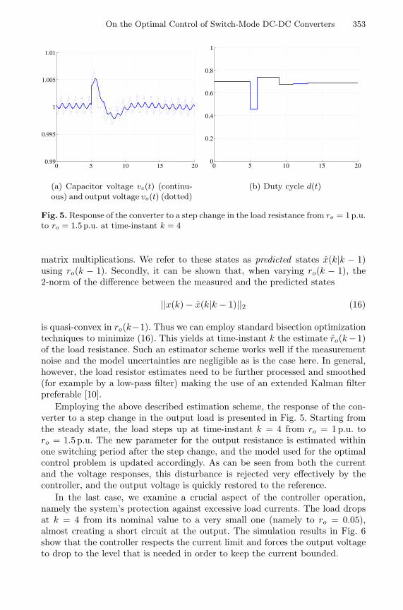
Fig. 5. Response of the converter to a step change in the load resistance from ro = 1 p.u.to ro = 1.5 p.u. at time-instant k = 4
matrix multiplications. We refer to these states as predicted states x(k|k − 1)using ro(k − 1). Secondly, it can be shown that, when varying ro(k − 1), the2-norm of the difference between the measured and the predicted states
||x(k) − x(k|k − 1)||2 (16)
is quasi-convex in ro(k−1). Thus we can employ standard bisection optimizationtechniques to minimize (16). This yields at time-instant k the estimate ro(k −1)of the load resistance. Such an estimator scheme works well if the measurementnoise and the model uncertainties are negligible as is the case here. In general,however, the load resistor estimates need to be further processed and smoothed(for example by a low-pass filter) making the use of an extended Kalman filterpreferable [10].
Employing the above described estimation scheme, the response of the con-verter to a step change in the output load is presented in Fig. 5. Starting fromthe steady state, the load steps up at time-instant k = 4 from ro = 1 p.u. toro = 1.5 p.u. The new parameter for the output resistance is estimated withinone switching period after the step change, and the model used for the optimalcontrol problem is updated accordingly. As can be seen from both the currentand the voltage responses, this disturbance is rejected very effectively by thecontroller, and the output voltage is quickly restored to the reference.
In the last case, we examine a crucial aspect of the controller operation,namely the system’s protection against excessive load currents. The load dropsat k = 4 from its nominal value to a very small one (namely to ro = 0.05),almost creating a short circuit at the output. The simulation results in Fig. 6show that the controller respects the current limit and forces the output voltageto drop to the level that is needed in order to keep the current bounded.

354 T. Geyer, G. Papafotiou, and M. Morari
0 5 10 15 20 25 30 35 40 45 500
2
4
6
8
(a) Inductor current i�(t)
0 5 10 15 20 25 30 35 40 45 500
0.2
0.4
0.6
0.8
1
1.2
(b) Capacitor voltage vc(t) (continu-ous) and output voltage vo(t) (dotted)
0 5 10 15 20 25 30 35 40 45 500
0.2
0.4
0.6
0.8
1
(c) Duty cycle d(t)
Fig. 6. Response of the converter to a step change in the load resistance from ro = 1 p.u.to ro = 0.05 p.u. at time-instant k = 4
This example shows that the two control objectives minimize the outputvoltage error and respect the constraint on the inductor current are potentiallycontradicting each other. By putting a very large penalty on the violation ofthe soft constraint, we have prioritized these objectives making sure that thelatter objective is always fulfilled and the converter is not destroyed by excessivecurrent. Such a feature is utilized in all practical applications through variousprotection schemes, but is usually not considered as part of the controller design.

On the Optimal Control of Switch-Mode DC-DC Converters 355
5 Conclusions and Outlook
In this paper, we have presented a new solution approach to the optimal con-trol problem of fixed frequency switch-mode DC-DC converters using hybridsystems methodologies. A novel N -step model was introduced to capture thehybrid nature of these systems within one switching period, and an optimal con-trol problem was formulated and solved online. The use of MPC has allowed usto explicitly take into account during the controller design physical constraints,such as the restriction of the duty cycle between zero and one, and safety con-straints, such as current limiting. Simulation results have been provided whichdemonstrate that this approach leads to a closed-loop system with very favorabledynamical properties.
This study has been limited to the case where the state-updates and the pro-posed load estimation scheme are considered to be ideal. These assumptions rep-resent shortcomings that in the course of further research need to be addressed.In particular, the robustness of the proposed control scheme with respect tomodel uncertainties and measurement noise, and the asymptotic stability of theclosed-loop system need to be investigated. Furthermore, the online solution ofthe optimal control problem requires computation times that are well abovethe sampling times used in real-life applications. Therefore, the experimentalverification of the foreseen benefits of the proposed approach also requires thecomputation of the optimal state-feedback control law parameterized over thestate space. This operation reduces the online optimization involving MILPs toa simple search in a look-up table requiring only matrix multiplications.
References
1. A. Bemporad, F. Borrelli, and M. Morari. Piecewise linear optimal controllers forhybrid systems. In Proceedings American Control Conference, pages 1190–1194,Chicago, IL, June 2000.
2. A. Bemporad and M. Morari. Control of systems integrating logic, dynamics, andconstraints. Automatica, 35(3):407–427, March 1999.
3. F. Borrelli. Constrained Optimal Control of Linear and Hybrid Systems, volume290 of Lecture Notes in Control and Information Sciences. Springer, 2003.
4. R.W. Erickson, S. Cuk, and R. D. Middlebrook. Large signal modeling and analysisof switching regulators. In IEEE Power Electronics Specialists Conference Records,pages 240–250, 1982.
5. F. Garofalo, P. Marino, S. Scala, and F. Vasca. Control of DC/DC converters withlinear optimal feedback and nonlinear feedforward. IEEE Transactions on PowerElectronics, 9(6):607–615, November 1994.
6. T. Geyer, F. D. Torrisi, and M. Morari. Efficient mode enumeration of composi-tional hybrid systems. In A. Pnueli and O. Maler, editors, Hybrid Systems: Com-putation and Control, volume 2623 of Lecture Notes in Computer Science, pages216–232. Springer-Verlag, 2003.
7. T. Gupta, R. R. Boudreaux, R. M. Nelms, and J. Y. Hung. Implementation of afuzzy controller for DC-DC converters using an inexpensive 8-b microcontroller.IEEE Transactions on Industrial Electronics, 44(5):661–669, October 1997.

356 T. Geyer, G. Papafotiou, and M. Morari
8. D. C. Hamill, J. H. B. Deane, and D. Jefferies. Modeling of chaotic DC-DC con-verters by iterated nonlinear mappings. IEEE Transactions on Power Electronics,7(1):25–36, January 1992.
9. S. Hiti and D. Borojevic. Robust nonlinear control for the boost converter. IEEETransactions on Power Electronics, 10(6):651–658, November 1995.
10. A. H. Jazwinski. Stochastic Processes and Filtering Theory. Academic Press, 1970.11. J.G. Kassakian, M.F. Schlecht, and G.C. Verghese. Principles of Power Electronics.
Addison-Wesley, 1991.12. M. K. Kazimierczuk and A. Massarini. Feedforward control dynamic of DC/DC
PWM boost converter. IEEE Transactions on Circuits and Systems-I: Fundamen-tal Theory and Applications, 44(2):143–149, February 1997.
13. M. K. Kazimierczuk and L. A. Starman. Dynamic performance of PWM DC/DCboost converter with input voltage feedforward control. IEEE Transactions onCircuits and Systems-I: Fundamental Theory and Applications, 46(12):1473–1481,December 1999.
14. G.Th. Kostakis, S.N. Manias, and N.I. Margaris. A generalized method for cal-culating the RMS values of switching power converters. IEEE Transactions onPower Electronics, 15(4):616–625, July 2000.
15. F. H. F. Leung, P. K. S. Tam, and C. K. Li. The control of switching DC-DCconverters – a general LQR problem. IEEE Transactions on Industrial Electronics,38(1):65–71, February 1991.
16. F. H. F. Leung, P. K. S. Tam, and C. K. Li. An improved LQR-based controllerfor switching DC-DC converters. IEEE Transactions on Industrial Electronics,40(5):521–528, October 1993.
17. B. Lincoln. Dynamic Programming and Time-Varying Delay Systems. PhD thesis,Department of Automatic Control, Lund Institute of Technology, Sweden, 2003.
18. J.M. Maciejowski. Predictive Control. Prentice Hall, 2002.19. R. D. Middlebrook and S. Cuk. A general unified approach to modeling switching
power converter stages. In IEEE Power Electronics Specialists Conference Records,pages 18–34, 1976.
20. N. Mohan, T. M. Undeland, and W. P. Robbins. Power Electronics: Converters,Applications and Design. Wiley, 1989.
21. H. S. Ramirez. Nonlinear P-I controller design for switchmode DC-to-DC powerconverters. 38(4):410–417, April 1991.
22. S. R. Sanders and G. C. Verghese. Lyapunov-based control for switched powerconverters. IEEE Transactions on Power Electronics, 7(1):17–23, January 1992.
23. M. Senesky, G. Eirea, and T. J. Koo. Hybrid modelling and control of powerelectronics. In A. Pnueli and O. Maler, editors, Hybrid Systems: Computationand Control, volume 2623 of Lecture Notes in Computer Science, pages 450–465.Springer-Verlag, 2003.
24. F.D. Torrisi and A. Bemporad. Hysdel — a tool for generating computationalhybrid models for analysis and synthesis problems. Technical Report AUT02-03,Automatic Control Laboratory ETH Zurich, http://control.ee.ethz.ch/, 2002.To appear in IEEE Transactions on Control Systems Technology.
Related Documents