231 Commerce Dr. Montgomeryville, PA 18936 Tel: 215-412-4445 Fax: 215-412-4409 Email: [email protected] 138 Industrial Loop West, Orange Park, FL 32073 Tel: 904-541-1655 Fax: 904-541-1657 Email: [email protected] *ALL STATED SPECIFICATIONS ARE SUBJECT TO UPDATE WITHOUT NOTICE OR OBLIGATION. B1, 4/F., Luen Ming Hing Factory Building 36 Mok Cheong St., To Kwa Wan, Kowloon, H. K. Tel: 852-2760-4188 Fax: 852-2760-4177 Email: [email protected] Website: www.firedamper.com Lloyd Industries Inc. 2017 APPLICATION SHEET CEILING RADIATION DAMPERS These ceiling dampers are Classified by Underwriters Laboratories, Inc. as to heat barriers in the Fire Resistance Directory under the category of Ceiling Dampers (CABS). Refer to the classification information in the back of the Fire Resistance Directory regarding the use of these dampers in the various floor-ceiling or roof-ceiling assemblies. Ceiling dampers and the associated components (surface mounted diffusers or grilles, ducts, etc.) which are to be constructed of steel, are installed in the ceiling to maintain the hourly ratings of the floor-ceiling or roof ceiling assemblies which are rated 3 hours or less. The damper/surface mounted diffuser shall be installed as shown on the installation sheet. The damper shall be installed as shown on the installation sheet. 12 SWG hanger wires, minimum of 3 wires are to be used to support the round ceiling dampers. Optional support method. The ceiling damper/ surface mounted diffuser assembly uses two #16 gauge cold-rolled steel support channels. The two 1-1/2 inch or 2 inch, No.16 gauge cold-rolled steel channels with 1/2 inch flanges, are to be attached to the top of the damper frame with 3/16" bolts of 3/8 inch minimum length. A minimum of two bolts per damper are required. Each channel is to be supported at each end by 12 SWG wire attached to the struc- tural members. All hanger wires shall be supported directly from the structural members of the floor or roof by vertical (not diagonal) hanger wires. Cold-rolled channels shall be used as required to insure that the grid and damper are supported from the structural members by vertical hanger wires (not diagonal). The flange on the surface mounted diffuser at the ceiling membrane level shall provide a minimal 1 inch. Support for the ceiling panels. Size of hole cut in the panel for passage of the duct drop shall be no more than 1/8 inch larger than opening for the damper. When cutting of a main runner or cross tee is needed, a 1/2 inch clearance must be maintained between the cut end of the main runner or cross tee and the damper. A 12 SWG hanger wire shall be installed near each end of the cut main runner or cross tee. No more than one main runner or cross tee may be cut when penetrating the ceiling membrane. The steel diffusers shall be attached to the damper with No. 8 sheet metal screws, 3/16" tubular steel rivets, 3/16" diameter by 1/2 inch long steel bolts, or 1/4" tack welds. Minimum of three connections, 6 inches OC. A steel clamp or No. 16 SWG minimum steel wire shall fasten the flex air duct to the damper when flex air ducts are used to connect the main duct to the damper/diffuser assembly. The flex air duct shall be Class 0 or 1 and bear the UL listing Mark- refer to the UL "Gas and oil Equipment Directory". Maximum length of flexible air duct shall not exceed 14 ft- 0 in. length. The flexible air duct shall not rest on the back surface of the ceiling grid or panels and provide a min. of 4" clearance. The flexible air duct shall not interfere with the closing of the damper. MODEL CRD-55 and CRD-55-EA (ROUND) NOTE: Figure 1– Application sheet shows ceiling plenum with non-ducted supply or return. See installation instructions (Figure 1A) for support channel method of installation used for ducted supply or return. 1. DAMPER 2. GRILLE FRAME (20 GAUGE MINIMUM) 3. CEILING GRID (UL CLASSIFIED) 4. 12 GAUGE STEEL WIRE 5. CEILING MATERIAL (UL CLASSIFIED) 6. HANGER STRAP ITEM FIGURE 1 Maximum Size Maximum Diameter Minimum Diameter 452 SQ.IN. 24” 4” ROUND CEILING DAMPER SIZE LIMITATION LLOYD INDUSTRIES INC. WWW.FIREDAMPER.COM INSTALLATION INSTRUCTIONS AND THE PRODUCTS SPECIFIED, ARE IN CONFORMANCE TO ALL OF UNDERWRITERS LABORATORIES REQUIREMENTS 555C 200

Welcome message from author
This document is posted to help you gain knowledge. Please leave a comment to let me know what you think about it! Share it to your friends and learn new things together.
Transcript

231 Commerce Dr. Montgomeryville, PA 18936
Tel: 215-412-4445 Fax: 215-412-4409
Email: [email protected]
138 Industrial Loop West, Orange Park, FL 32073
Tel: 904-541-1655 Fax: 904-541-1657
Email: [email protected]
*ALL STATED SPECIFICATIONS ARE SUBJECT TO UPDATE WITHOUT NOTICE OR OBLIGATION.
B1, 4/F., Luen Ming Hing Factory Building
36 Mok Cheong St.,
To Kwa Wan, Kowloon, H. K.
Tel: 852-2760-4188 Fax: 852-2760-4177
Email: [email protected] Website: www.firedamper.com
Lloyd Industries Inc. 2017
APPLICATION SHEET
CEILING RADIATION DAMPERS
These ceiling dampers are Classified by Underwriters Laboratories, Inc. as to heat barriers in the Fire Resistance Directory under the category of Ceiling
Dampers (CABS). Refer to the classification information in the back of the Fire Resistance Directory regarding the use of these dampers in the various
floor-ceiling or roof-ceiling assemblies. Ceiling dampers and the associated components (surface mounted diffusers or grilles, ducts, etc.) which are to be
constructed of steel, are installed in the ceiling to maintain the hourly ratings of the floor-ceiling or roof ceiling assemblies which are rated 3 hours or less.
The damper/surface mounted diffuser shall be installed as shown on the installation sheet. The damper shall be installed as shown on the installation sheet.
12 SWG hanger wires, minimum of 3 wires are to be used to support the round ceiling dampers.
Optional support method. The ceiling damper/ surface mounted diffuser assembly uses two #16 gauge cold-rolled steel support channels. The two 1-1/2
inch or 2 inch, No.16 gauge cold-rolled steel channels with 1/2 inch flanges, are to be attached to the top of the damper frame with 3/16" bolts of 3/8 inch
minimum length. A minimum of two bolts per damper are required. Each channel is to be supported at each end by 12 SWG wire attached to the struc-
tural members.
All hanger wires shall be supported directly from the structural members of the floor or roof by vertical (not diagonal) hanger wires. Cold-rolled channels
shall be used as required to insure that the grid and damper are supported from the structural members by vertical hanger wires (not diagonal).
The flange on the surface mounted diffuser at the ceiling membrane level shall provide a minimal 1 inch. Support for the ceiling panels. Size of hole cut
in the panel for passage of the duct drop shall be no more than 1/8 inch larger than opening for the damper.
When cutting of a main runner or cross tee is needed, a 1/2 inch clearance must be maintained between the cut end of the main runner or cross tee and the
damper. A 12 SWG hanger wire shall be installed near each end of the cut main runner or cross tee. No more than one main runner or cross tee may be cut
when penetrating the ceiling membrane.
The steel diffusers shall be attached to the damper with No. 8 sheet metal screws, 3/16" tubular steel rivets, 3/16" diameter by 1/2 inch long steel bolts, or
1/4" tack welds. Minimum of three connections, 6 inches OC. A steel clamp or No. 16 SWG minimum steel wire shall fasten the flex air duct to the
damper when flex air ducts are used to connect the main duct to the damper/diffuser assembly. The flex air duct shall be Class 0 or 1 and bear the UL
listing Mark- refer to the UL "Gas and oil Equipment Directory". Maximum length of flexible air duct shall not exceed 14 ft- 0 in. length. The flexible air
duct shall not rest on the back surface of the ceiling grid or panels and provide a min. of 4" clearance. The flexible air duct shall not interfere with the
closing of the damper.
MODEL CRD-55 and CRD-55-EA (ROUND)
NOTE:
Figure 1– Application sheet shows ceiling plenum
with non-ducted supply or return. See installation
instructions (Figure 1A) for support channel method
of installation used for ducted supply or return.
1. DAMPER
2. GRILLE FRAME (20 GAUGE MINIMUM)
3. CEILING GRID (UL CLASSIFIED)
4. 12 GAUGE STEEL WIRE
5. CEILING MATERIAL (UL CLASSIFIED)
6. HANGER STRAP
ITEM
FIGURE 1
Maximum Size Maximum Diameter Minimum Diameter
452 SQ.IN. 24” 4”
ROUND CEILING DAMPER SIZE LIMITATION
LLOYD INDUSTRIES INC. WWW.FIREDAMPER.COM
INSTALLATION INSTRUCTIONS
AND THE PRODUCTS SPECIFIED,
ARE IN CONFORMANCE TO ALL OF
UNDERWRITERS LABORATORIES
REQUIREMENTS 555C
200

These ceiling dampers are Classified by Underwriters Laboratories, Inc. as to
heat barriers in the Fire Resistance Directory under the category of Ceiling
Dampers (CABS). Refer to the Classification information in the back of the Fire
Resistance Directory regarding the use of these dampers in the various floor /
ceiling or Roof / ceiling assemblies. Ceiling dampers and the associated compo-
nents (surface mounted diffusers or grilles, ducts, etc.) which are to be con-
structed of steel, are installed in the ceiling to maintain the hourly ratings of the
floor-ceiling or roof-ceiling assemblies which are rated 3 hours or less.
Notes:
1. Before installing damper, Model 55 CRD (round), open blades and hook fusible link over link catch on opposite blade. Bend down link catch to secure link
in position.
2. Support the duct with (2) 16 Ga. cold-rolled steel support channels, 1-1/2 or 2 inches deep with 1/2 inch flanges. Place the support channels at the bottom of
the duct adjacent to both sides of the duct drop. Use 12 SWG galvanized steel hanger wire to independently support channels from the structural members of
the floor or roof above. All hanger wires shall supported directly from the structural members of the floor or the roof by vertical (not diagonal) hanger wires.
Cold-rolled channels shall be used as required to insure that the grid and damper are supported from the structural members by vertical hanger wires (not di-
agonal).
3. Install the ceiling damper in the duct drop using 3/16 inch diameter by 1/2 inch long steel bolts, No. 8 by 1/2 inch steel sheet metal screws or 3/16 inch di-
ameter by 1/2 inch long steel bolts, No. 8 by 1/2 inch steel sheet metal screws or 3/16 inch diameter steel rivets at 6 inches o.c. and a minimum of (3) places.
4. The clearance between each side of the ceiling damper and the duct drop shall be 1/8 inch maximum.
5. Maximum size of Model 55 CRD (round) is 24 inches in diameter.
6. Duct outlets in lay-in ceilings should be field located in an acoustical ceiling panel or tile. Where it is necessary to cut a main runner or cross tee, each cut
end shall be supported by a vertical 12 gauge hanger wire. A 1/2 inch clearance shall be maintained between the duct outlet and each cut end of main runner or
cross tee. The duct outlet shall be located so that no more than one main runner or cross tee is cut when penetrating the ceiling membrane.
7. Steel grille or diffuser to be attached to the duct drop or ceiling damper using No. 8 by 1/2 inch long sheet metal screws at 6 inches o.c. and a minimum of
(3) places.
231 Commerce Dr. Montgomeryville, PA 18936
Tel: 215-412-4445 Fax: 215-412-4409
Email: [email protected]
138 Industrial Loop West, Orange Park, FL 32073
Tel: 904-541-1655 Fax: 904-541-1657
Email: [email protected]
*ALL STATED SPECIFICATIONS ARE SUBJECT TO UPDATE WITHOUT NOTICE OR OBLIGATION.
B1, 4/F., Luen Ming Hing Factory Building
36 Mok Cheong St.,
To Kwa Wan, Kowloon, H. K.
Tel: 852-2760-4188 Fax: 852-2760-4177
Email: [email protected] Website: www.firedamper.com
Lloyd Industries Inc. 2017
INSTALLATION INSTRUCTIONS
CEILING RADIATION DAMPERS
MODEL CRD-55 and CRD-55-EA (ROUND)
1. MODEL 55 CRD (ROUND) CEILING RADIATION
DAMPER
2. STEEL DUCT DROP
3. BRANCH DUCT
4. 12 SWG HANGER WIRES (4) MIN REQUIRED
5. STEEL SUPPORT CHANNELS
6. MOUNTING FASTENERS (BOLTS, SCREWS, RIVETS)
7. SURFACE MOUNTED STEEL GRILLE OR DIFFUSER
8. CEILING : ACOUSTICAL PANEL (LAY-IN) ACOUSTI-
CAL TILE OR GYPSUM WALLBOARD
ITEM
Maximum Size Maximum Diameter Minimum Diameter
452 SQ.IN. 24” 4”
ROUND CEILING DAMPER SIZE LIMITATION
LLOYD INDUSTRIES INC. WWW.FIREDAMPER.COM
INSTALLATION INSTRUCTIONS
AND THE PRODUCTS SPECIFIED,
ARE IN CONFORMANCE TO ALL OF
UNDERWRITERS LABORATORIES
REQUIREMENTS 555C
201

231 Commerce Dr. Montgomeryville, PA 18936
Tel: 215-412-4445 Fax: 215-412-4409
Email: [email protected]
138 Industrial Loop West, Orange Park, FL 32073
Tel: 904-541-1655 Fax: 904-541-1657
Email: [email protected]
*ALL STATED SPECIFICATIONS ARE SUBJECT TO UPDATE WITHOUT NOTICE OR OBLIGATION.
B1, 4/F., Luen Ming Hing Factory Building
36 Mok Cheong St.,
To Kwa Wan, Kowloon, H. K.
Tel: 852-2760-4188 Fax: 852-2760-4177
Email: [email protected] Website: www.firedamper.com
Lloyd Industries Inc. 2017
APPLICATION SHEET
CEILING RADIATION DAMPERS
MODEL CRD-50 and CRD-50-EA (RECTANGULAR)
1. DAMPER
2. GRILLE FRAME (20 GAUGE MINIMUM)
3. CEILING GRID (UL CLASSIFIED)
4. 12 GAUGE STEEL WIRE
5. CEILING MATERIAL (UL CLASSIFIED)
ITEM
These ceiling dampers are Classified by Underwriters Laboratories, Inc. as to heat barriers in the Fire Resistance Directory under the
category of Ceiling Dampers (CABS). Refer to the Classification information in the back of the Fire Resistance Directory regarding the
use of these dampers in the various floor-ceiling or roof-ceiling assembles. Ceiling dampers and the associated components (surface
mounted diffusers or grilles, ducts, etc.) which are to be constructed of steel, are installed in the ceiling to maintain the hourly ratings of
the floor-ceiling assemblies which are rated 3 hours or less.
The damper/surface mounted diffuser shall be installed as shown on installation sheet. The damper on the opposite sides shall be con-
nected to support channels (16 MSG by 1-1/2 or 2 inch channel) with 3/16 inch diameter by 1/2 inch long steel bolts, No. 8 by 1/2 inch
steel sheet metal screws or 3/16 inch diameter steel rivets at 6 inches OC minimum 3 per side.
The damper assembly shall be hung with 12 SWG minimum hanger wires at each of the channel ends. All hanger wires shall be sup-
ported directly from the structural members of the floor or roof by vertical (not diagonal) hanger wires. Cold-rolled channels shall be
used as required to insure that the grid and damper are supported from the structural members by vertical hanger wires (not diagonal).
The flange on the surface mounted diffuser at the ceiling membranes level shall provide a minimum 1 inch. Support for the ceiling pan-
els. Size of hole cut in the panel for passage of the duct drop shall be more than 1/8 inch. Larger than opening for the damper.
When cutting of a main runner or cross tee is needed, a 1/2 inch clearance must be maintained between the cut end of the main runner or
cross tee and the damper. A 12 SWG hanger wire shall be installed near each end of the cut main runner or cross tee. No more than one
main runner or cross tee may be cut when penetrating the ceiling membrane.
The steel diffusers shall be attached to the damper with No. 8 sheet metal screws, 3/16" tubular steel rivets, 3/16 inch diameter by half
inch long steel bolts, or 1/4" tack welds. Minimum of three connections, 6 inches OC.
RECTANGULAR CEILING DAMPER SIZE LIMITATION
Maximum Size Maximum width Maximum length Minimum width Minimum length
576 SQ.IN. 24” 24” 4” 4”
LLOYD INDUSTRIES INC. WWW.FIREDAMPER.COM
INSTALLATION INSTRUCTIONS
AND THE PRODUCTS SPECIFIED,
ARE IN CONFORMANCE TO ALL OF
UNDERWRITERS LABORATORIES
REQUIREMENTS 555C
202

231 Commerce Dr. Montgomeryville, PA 18936
Tel: 215-412-4445 Fax: 215-412-4409
Email: [email protected]
138 Industrial Loop West, Orange Park, FL 32073
Tel: 904-541-1655 Fax: 904-541-1657
Email: [email protected]
*ALL STATED SPECIFICATIONS ARE SUBJECT TO UPDATE WITHOUT NOTICE OR OBLIGATION.
B1, 4/F., Luen Ming Hing Factory Building
36 Mok Cheong St.,
To Kwa Wan, Kowloon, H. K.
Tel: 852-2760-4188 Fax: 852-2760-4177
Email: [email protected] Website: www.firedamper.com
Lloyd Industries Inc. 2017
INSTALLATION INSTRUCTIONS
CEILING RADIATION DAMPERS
MODEL CRD-50 and CRD-50-EA (RECTANGULAR)
RECTANGULAR CEILING DAMPER SIZE LIMITATION
Maximum Size Maximum width Maximum length Minimum width Minimum length
576 SQ.IN. 24” 24” 4” 4”
1. MODEL 50 CRD (RECTANGULAR) CEILING RADIA-
TION DAMPER
2. STEEL DUCT DROP
3. BRANCH DUCT
4. 12 SWG HANGER WIRES (4) MIN REQUIRED
5. STEEL SUPPORT CHANNELS
6. MOUNTING FASTENERS (BOLTS, SCREWS, RIVETS)
7. SURFACE MOUNTED STEEL GRILLE OR DIFFUSER
8. CEILING : ACOUSTICAL PANEL (LAY-IN) ACOUSTI-
CAL TILE OR GYPSUM WALLBOARD
ITEM
These ceiling dampers are Classified by Underwriters Laboratories, Inc. as to
heat barriers in the Fire Resistance Directory under the category of Ceiling
Dampers (CABS). Refer to the Classification information in the back of the Fire
Resistance Directory regarding the use of these dampers in the various floor /
ceiling or Roof / ceiling assemblies. Ceiling dampers and the associated compo-
nents (surface mounted diffusers or grilles, ducts, etc.) which are to be con-
structed of steel, are installed in the ceiling to maintain the hourly ratings of the
floor-ceiling or roof-ceiling assemblies which are rated 3 hours or less.
Notes:
1. Before installing damper, Model 50 CRD (rectangular), open blades and hook fusible link over link catch on opposite blade. Bend down link catch to secure
link in position.
2. Support the duct with (2) 16 Ga. cold-rolled steel support channels, 1-1/2 or 2 inches deep with 1/2 inch flanges. Place the support channels at the bottom of
the duct adjacent to both sides of the duct drop. Use 12 SWG galvanized steel hanger wire to independently support channels from the structural members of
the floor or roof above. All hanger wires shall supported directly from the structural members of the floor or the roof by vertical (not diagonal) hanger wires.
Cold-rolled channels shall be used as required to insure that the grid and damper are supported from the structural members by vertical hanger wires (not di-
agonal).
3. Install the ceiling damper in the duct drop using 3/16 inch diameter by 1/2 inch long steel bolts, No. 8 by 1/2 inch steel sheet metal screws or 3/16 inch di-
ameter by 1/2 inch long steel bolts, No. 8 by 1/2 inch steel sheet metal screws or 3/16 inch diameter steel rivets at 6 inches o.c. and a minimum of (3) places.
4. The clearance between each side of the ceiling damper and the duct drop shall be 1/8 inch maximum.
5. Maximum size of Model 50 CRD (rectangular) is 24 inches x 24 inches.
6. Duct outlets in lay-in ceilings should be field located in an acoustical ceiling panel or tile. Where it is necessary to cut a main runner or cross tee, each cut
end shall be supported by a vertical 12 gauge hanger wire. A 1/2 inch clearance shall be maintained between the duct outlet and each cut end of main runner or
cross tee. The duct outlet shall be located so that no more than one main runner or cross tee is cut when penetrating the ceiling membrane.
7. Steel grille or diffuser to be attached to the duct drop or ceiling damper using No. 8 by 1/2 inch long sheet metal screws at 6 inches o.c. and a minimum of
(3) places.
LLOYD INDUSTRIES INC. WWW.FIREDAMPER.COM
INSTALLATION INSTRUCTIONS
AND THE PRODUCTS SPECIFIED,
ARE IN CONFORMANCE TO ALL OF
UNDERWRITERS LABORATORIES
REQUIREMENTS 555C
203
231 Commerce Dr. Montgomeryville, PA 18936
Tel: 215-412-4445 Fax: 215-412-4409
Email: [email protected]
138 Industrial Loop West, Orange Park, FL 32073
Tel: 904-541-1655 Fax: 904-541-1657
Email: [email protected]
*ALL STATED SPECIFICATIONS ARE SUBJECT TO UPDATE WITHOUT NOTICE OR OBLIGATION.
B1, 4/F., Luen Ming Hing Factory Building
36 Mok Cheong St.,
To Kwa Wan, Kowloon, H. K.
Tel: 852-2760-4188 Fax: 852-2760-4177
Email: [email protected] Website: www.firedamper.com
Lloyd Industries Inc. 2017
INSTALLATION INSTRUCTIONS
CEILING RADIATION DAMPERS
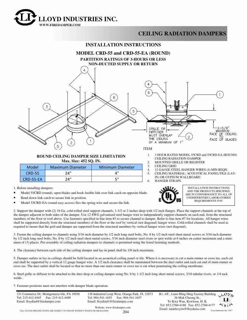
MODEL CRD-55 and CRD-55-EA (ROUND)
1. Before installing dampers:
• Model 55CRD (round), open blades and hook fusible link over link catch on opposite blade.
• Bend down link catch to secure link in position.
• Model 55CRD-EA (round easy access) flex the spring wire and secure the link.
2. Support the damper with (2) 16 Ga. cold-rolled steel support channels, 1-1/2 or 2 inches deep with 1/2 inch flanges. Place the support channels at the top of
the damper adjacent to both sides of the damper. Use 12 SWG galvanized steel hanger wire to independently support channels on each end, from the structural
members of the floor or roof above. Use fasteners specified in line item #3 to secure channel to damper. Refer to line item #7 for locations. All hanger wires
shall be supported directly from the structural members of the floor or the roof by vertical (not diagonal) hanger wires. Cold-rolled channels shall be used as
required to insure that the grid and damper are supported from the structural members by vertical hanger wires (not diagonal).
3. Fasten the ceiling damper to channels using 3/16 inch diameter by 1/2 inch long steel bolts, No. 8 by 1/2 inch steel sheet metal screws or 3/16 inch diameter
by 1/2 inch long steel bolts, No. 8 by 1/2 inch steel sheet metal screws, 3/16 inch diameter steel rivets or spot welds at 6 inches on center maximum and a mini-
mum of (3) places. Pre-assembly of ceiling radiation dampers to channels is permitted using the listed fastening methods.
4. The clearance between each side of the ceiling damper and lay-in panel shall be 1/8 inch maximum.
5. Damper outlets in lay-in ceilings should be field located in an acoustical ceiling panel or tile. Where it is necessary to cut a main runner or cross tee, each cut
end shall be supported by a vertical 12 gauge hanger wire. A 1/2 inch clearance shall be maintained between the duct outlet and each cut end of main runner or
cross tee. The duct outlet shall be located so that no more than one main runner or cross tee is cut when penetrating the ceiling membrane.
6. Steel grille or diffuser to be attached to the duct drop or ceiling damper using No. 8 by 1-1/2 inch long sheet metal screws, 3/16 tubular rivets, or 1/4 tack
welds .
7. Fastener positions must not interfere with damper blade operation.
PARTITION RATINGS OF 3-HOURS OR LESS
NON-DUCTED SUPPLY OR RETURN
1. 3 HOUR RATED MODEL 55CRD and 55CRD-EA (ROUND)
CEILING RADIATION DAMPER
2. MOUNTED GRILLE OR REGISTER
3. CEILING GRID
4. 12 GAUGE STEEL HANGER WIRES (4) MIN REQD.
5. CEILING MATERIAL: ACOUSTICAL PANEL/TILE (LAY-
IN) OR GYPSUM WALLBOARD
6. HANGER STRAPS
ITEM
Model Maximum Diameter Minimum Diameter
CRD-55 24" 4"
CRD-55-EA 24" 5"
ROUND CEILING DAMPER SIZE LIMITATION
Max. Size: 452 SQ. IN.
LLOYD INDUSTRIES INC. WWW.FIREDAMPER.COM
INSTALLATION INSTRUCTIONS
AND THE PRODUCTS SPECIFIED,
ARE IN CONFORMANCE TO ALL OF
UNDERWRITERS LABORATORIES
REQUIREMENTS 555C
204

231 Commerce Dr. Montgomeryville, PA 18936
Tel: 215-412-4445 Fax: 215-412-4409
Email: [email protected]
138 Industrial Loop West, Orange Park, FL 32073
Tel: 904-541-1655 Fax: 904-541-1657
Email: [email protected]
*ALL STATED SPECIFICATIONS ARE SUBJECT TO UPDATE WITHOUT NOTICE OR OBLIGATION.
B1, 4/F., Luen Ming Hing Factory Building
36 Mok Cheong St.,
To Kwa Wan, Kowloon, H. K.
Tel: 852-2760-4188 Fax: 852-2760-4177
Email: [email protected] Website: www.firedamper.com
Lloyd Industries Inc. 2017
INSTALLATION INSTRUCTIONS
CEILING RADIATION DAMPERS
MODEL CRD-55 and CRD-55-EA (ROUND)
1. Before installing dampers:
• Model CRD 55 (round), open blades and hook fusible link over link catch on opposite blade.
• Bend down link catch to secure link in position.
• Model CRD 55-EA (round easy access) flex the spring wire and secure the link.
2. Support the damper with (2) 16 Ga. cold-rolled steel support channels, 1-1/2 or 2 inches deep with 1/2 inch flanges. Place the support channels at the top of
the damper adjacent to both sides of the damper. Use 12 SWG galvanized steel hanger wire to independently support channels on each end, from the structural
members of the floor or roof above. Use fasteners specified in line item #3 to secure channel to damper. Refer to line item #7 for locations. All hanger wires
shall be supported directly from the structural members of the floor or the roof by vertical (not diagonal) hanger wires. Cold-rolled channels shall be used as
required to insure that the grid and damper are supported from the structural members by vertical hanger wires (not diagonal).
3. Fasten the ceiling damper to channels using 3/16 inch diameter by 1/2 inch long steel bolts, No. 8 by 1/2 inch steel sheet metal screws or 3/16 inch diameter
by 1/2 inch long steel bolts, No. 8 by 1/2 inch steel sheet metal screws, 3/16 inch diameter steel rivets or spot welds at 6 inches on center maximum and a mini-
mum of (3) places. Pre-assembly of ceiling radiation dampers to channels is permitted using the listed fastening methods.
4. The clearance between each side of the ceiling damper and lay-in panel shall be 1/8 inch maximum.
5. Damper outlets in lay-in ceilings should be field located in an acoustical ceiling panel or tile. Where it is necessary to cut a main runner or cross tee, each cut
end shall be supported by a vertical 12 gauge hanger wire. A 1/2 inch clearance shall be maintained between the duct outlet and each cut end of main runner or
cross tee. The duct outlet shall be located so that no more than one main runner or cross tee is cut when penetrating the ceiling membrane.
6. Steel grille or diffuser to be attached to the duct drop or ceiling damper using No. 8 by 1-1/2 inch long sheet metal screws, 3/16 tubular rivets, or 1/4 tack
welds .
7. Fastener positions must not interfere with damper blade operation.
PARTITION RATINGS OF 3-HOURS OR LESS
DUCTED SUPPLY OR RETURN
1. 3-HOUR RATED MODEL CRD 55 and CRD 55-EA (ROUND)
CEILING RADIATION DAMPER
2. STEEL DUCT DROP, SLEEVE (LESS #3 PLENUM PERMITTED) 3. BRANCH DUCT
4. 12 SWG HANGER WIRES (4) MIN REQD
5. STEEL SUPPORT CHANNELS
6. MOUNTING FASTENERS (BOLTS, SCREWS, RIVETS)
7. MOUNTED STEEL, GRILLE, DIFFUSER, OR DROP DUCTING
8. CEILING : ACOUSTICAL PANEL (LAY-IN) ACOUSTICAL TILE
OR GYPSUM WALLBOARD
ITEM
Model Maximum Diameter Minimum Diameter
CRD-55 24" 4"
CRD-55-EA 24" 5"
ROUND CEILING DAMPER SIZE LIMITATIONS
Max. Size: 452 SQ. IN.
LLOYD INDUSTRIES INC. WWW.FIREDAMPER.COM
INSTALLATION INSTRUCTIONS
AND THE PRODUCTS SPECIFIED,
ARE IN CONFORMANCE TO ALL OF
UNDERWRITERS LABORATORIES
REQUIREMENTS 555C
205

231 Commerce Dr. Montgomeryville, PA 18936
Tel: 215-412-4445 Fax: 215-412-4409
Email: [email protected]
138 Industrial Loop West, Orange Park, FL 32073
Tel: 904-541-1655 Fax: 904-541-1657
Email: [email protected]
*ALL STATED SPECIFICATIONS ARE SUBJECT TO UPDATE WITHOUT NOTICE OR OBLIGATION.
B1, 4/F., Luen Ming Hing Factory Building
36 Mok Cheong St.,
To Kwa Wan, Kowloon, H. K.
Tel: 852-2760-4188 Fax: 852-2760-4177
Email: [email protected] Website: www.firedamper.com
Lloyd Industries Inc. 2017
INSTALLATION INSTRUCTIONS
CEILING RADIATION DAMPERS
MODEL CRD-50 and CRD-50-EA (RECTANGULAR)
1. Before installing dampers:
• Model CRD 50 (rectangular), open blades and hook fusible link over link catch on opposite blade.
• Bend down link catch to secure link in position.
• Model CRD 50-EA (rectangular easy access) flex the spring wire and secure the link.
2. Support the damper with (2) 16 Ga. cold-rolled steel support channels, 1-1/2 or 2 inches deep with 1/2 inch flanges. Place the support channels at the top of
the damper adjacent to both sides of the damper. Use 12 SWG galvanized steel hanger wire to independently support channels on each end, from the structural
members of the floor or roof above. Use fasteners specified in line item #3 to secure channel to damper. Refer to line item #7 for locations. All hanger wires
shall be supported directly from the structural members of the floor or the roof by vertical (not diagonal) hanger wires. Cold-rolled channels shall be used as
required to insure that the grid and damper are supported from the structural members by vertical hanger wires (not diagonal).
3. Fasten the ceiling damper to channels using 3/16 inch diameter by 1/2 inch long steel bolts, No. 8 by 1/2 inch steel sheet metal screws or 3/16 inch diameter
by 1/2 inch long steel bolts, No. 8 by 1/2 inch steel sheet metal screws, 3/16 inch diameter steel rivets or spot welds at 6 inches on center maximum and a mini-
mum of (3) places. Pre-assembly of ceiling radiation dampers to channels is permitted using the listed fastening methods.
4. The clearance between each side of the ceiling damper and lay-in panel shall be 1/8 inch maximum.
5. Damper outlets in lay-in ceilings should be field located in an acoustical ceiling panel or tile. Where it is necessary to cut a main runner or cross tee, each cut
end shall be supported by a vertical 12 gauge hanger wire. A 1/2 inch clearance shall be maintained between the duct outlet and each cut end of main runner or
cross tee. The duct outlet shall be located so that no more than one main runner or cross tee is cut when penetrating the ceiling membrane.
6. Steel grille or diffuser to be attached to the duct drop or ceiling damper using No. 8 by 1-1/2 inch long sheet metal screws, 3/16 tubular rivets, or 1/4 tack
welds .
7. Fastener positions must not interfere with damper blade operation.
PARTITION RATINGS OF 3-HOURS OR LESS
DUCTED SUPPLY OR RETURN
1. 3-HOUR RATED MODEL CRD 50 and CRD 50-EA
(RECTANGULAR) CEILING RADIATION DAMPER
2. STEEL DUCT DROP, SLEEVE (LESS #3 PLENUM PERMITTED) 3. BRANCH DUCT, PLENUM
4. 12 SWG HANGER WIRES (4) MIN REQD
5. STEEL SUPPORT CHANNELS
6. MOUNTING FASTENERS (BOLTS, SCREWS, RIVETS)
7. MOUNTED STEEL, GRILLE, DIFFUSER, OR DROP DUCTING
8. CEILING : ACOUSTICAL PANEL (LAY-IN) ACOUSTICAL TILE
OR GYPSUM WALLBOARD
ITEM
RECTANGULAR CEILING DAMPER SIZE LIMITATIONS
Max. Size: 576 SQ. IN.
Model Max. Width Max. Length Min. Width Min. Length
CRD-50 24" 24" 4" 4"
CRD-50-EA 24" 24" 6" 6”
LLOYD INDUSTRIES INC. WWW.FIREDAMPER.COM
INSTALLATION INSTRUCTIONS
AND THE PRODUCTS SPECIFIED,
ARE IN CONFORMANCE TO ALL OF
UNDERWRITERS LABORATORIES
REQUIREMENTS 555C
206

ITEM
Model CRD50 and CRD50-EA Ceiling Radiation Dampers are Classified to
UL 555C as 3 HR or less heat barriers illustrated in the UL Fire Resistance Directory. Refer
to the partition classification information in the Fire Resistance Directory regarding the use of
these dampers in the various floor-ceiling and roof-ceiling assemblies. Ceiling dampers and
the associated components (diffusers, grilles, ducts, etc. which are to be constructed of steel
are installed in the ceiling to maintain the hourly ratings of these rated floor-ceiling, roof-
ceiling, assemblies. The combination of damper, partition, and installation establish this 3 HR
or less Underwriters Laboratory Fire Rating.
Lloyd Industries MODEL CRD50 and CRD50-EA are laboratory approved for installation in
all 3 hr. or less rated fire barriers listed in the Underwriters Laboratory Fire Resistance Direc-
tory, where fire barriers are shown with partition penetrations. Fire barriers without penetra-
tions, and fire barriers not listed in the UL Fire Resistance Directory are not approved for
installations and require the use of "Special" Assemblies such as CRD50-BT, and CRD55-BT
Laboratory Approved Assemblies, or approval of local authorities. (See spec sheets for CRD-
BT Assemblies)
Notes:
1. Before installing the damper, CRD Model 50 (rectangle), and CRD Model 50-EA (rectangle) open the blades and hook the fusible link over the link
catch on the opposite blade. Bend down the link catch to secure the link in position. For CRD Model 50-EA flex the spring wire and secure the link.
2. Measure the actual spacing between the joists or other structural members. Allowing for a 3.00" flange at each mounting point. Cut and bend the
angles on both ends to 90 degrees. or the appropriate angle required. Mounting angles are fastened to joists or other structural members with a mini-
mum of two fasteners for each mounting point using #6 common nails or #8 x 1-1/4" long screws.
3. CRD Model 50 and CRD Model 50-EA are connected to the mounting angles with sheet metal screws, rivets, or bolts. Two connections on each
angle as a minimum. Note: fastener positions must not interfere with the damper blade operation.
4. CRD Models 50 and CRD Model 50-EA are connected to the stabilizing angles with sheet metal screws, rivets, or bolts. One connection on each
angle as a minimum. The stabilizing angles are to be mounted with one face of the angle flush to the ceiling material. Note: fastener positions must
not interfere with the damper blade operation.
5. The installation mounting position of the closed damper blade face must not exceed 2-5/8" from the face of the rated barrier.
6. Install the ceiling damper in the duct drop using 3/16 inch diameter by 1/2 inch long steel bolts, No. 8 by 1/2 inch steel sheet metal screws or 3/16
inch diameter by 1/2 inch long steel bolts, No. 8 by 1/2 inch steel sheet metal screws or 3/16 inch diameter steel rivets at 6 inches o.c. and a minimum
of (3) places. For flexible ducting; connect with draw clamps, #16 SWG wire, or cable ties as per SMACMA Standards requirements.
7. The clearance between each side of the ceiling damper and the duct drop shall be 1/8 inch maximum.
8. The maximum size of CRD Model 50 (rectangle) and CRD Model 50-EA (rectangle) is 24" W x 24" H.
9. Steel/Alum. grille or diffuser to be attached to the duct drop or ceiling damper using No. 8 by 1-1/2 inch lg.sheet metal
231 Commerce Dr. Montgomeryville, PA 18936
Tel: 215-412-4445 Fax: 215-412-4409
Email: [email protected]
138 Industrial Loop West, Orange Park, FL 32073
Tel: 904-541-1655 Fax: 904-541-1657
Email: [email protected]
*ALL STATED SPECIFICATIONS ARE SUBJECT TO UPDATE WITHOUT NOTICE OR OBLIGATION.
B1, 4/F., Luen Ming Hing Factory Building
36 Mok Cheong St.,
To Kwa Wan, Kowloon, H. K.
Tel: 852-2760-4188 Fax: 852-2760-4177
Email: [email protected] Website: www.firedamper.com
Lloyd Industries Inc. 2017
CEILING RADIATION DAMPERS
1. MODEL 50 CRD (RECTANGLE) CEILING RADIATION
DAMPER
2. STEEL DUCT DROP(LESS #3 PLENUM PERMITTED)
3. BRANCH PLENUM, OR PLENUM BOOT
4. HANGER ANGLES (2) 1-1/2 X 1-1/2 X 16 GAUGE
5. #6 COMMON NAILS OR #8 X 1-1/4 SCREWS
6. MOUNTING FASTENERS (BOLTS, SCREWS, RIVETS)
7. STEEL GRILLE, DIFFUSER, OR DROP DUCTING
8. CEILING : GYPSUM WALLBOARD
ACOUSTICAL TILE OR ACOUSTICAL PANEL (LAY-IN)
9. JOISTS, TRUSSES, BEAMS
10. STABILIZING ANGLES (2) 1/2 X 1-1/2 X 16 GA. X 3"
11. MOUNTING FASTENERS (BOLTS, SCREWS, RIVETS)
LLOYD INDUSTRIES INC. WWW.FIREDAMPER.COM
INSTALLATION INSTRUCTIONS
AND THE PRODUCTS SPECIFIED,
ARE IN CONFORMANCE TO ALL OF
UNDERWRITERS LABORATORIES
REQUIREMENTS 555C
GENERAL INSTALLATION INSTRUCTIONS
MODEL CRD-50 and CRD-50-EA (RECTANGLE)
3 HOUR OR LESS RATED PARTITIONS
207

ITEM
Model CRD55 and CRD55-EA Ceiling Radiation Dampers are Classified to UL
555C as 3 HR or less heat barriers illustrated in the UL Fire Resistance Directory. Refer to
the partition classification information in the Fire Resistance Directory regarding the use of
these dampers in the various floor-ceiling and roof-ceiling assemblies. Ceiling dampers and
the associated components (diffusers, grilles, ducts, etc. which are to be constructed of steel
are installed in the ceiling to maintain the hourly ratings of these rated floor-ceiling, roof-
ceiling, assemblies. The combination of damper, partition, and installation establish this 3 HR
or less Underwriters Laboratory Fire Rating.
Lloyd Industries MODEL CRD55 and CRD55-EA are laboratory approved for installation in
all 3 hr. or less rated fire barriers listed in the Underwriters Laboratory Fire Resistance Direc-
tory, where fire barriers are shown with partition penetrations. Fire barriers without penetra-
tions, and fire barriers not listed in the UL Fire Resistance Directory are not approved for
installations and require the use of "Special" Assemblies such as CRD50-BT, and CRD55-BT
Laboratory Approved Assemblies, or approval of local authorities. (See spec sheets for CRD-
BT Assemblies)
Notes:
1. Before installing the damper, CRD Model 55 (round), and CRD Model 55-EA (round) open the blades and hook the fusible link over the link catch
on the opposite blade. Bend down the link catch to secure the link in position. For CRD Model 55-EA flex the spring wire and secure the link.
2. Measure the actual spacing between the joists or other structural members. Allowing for a 3.00" flange at each mounting point. Cut and bend the
angles on both ends to 90 degrees. or the appropriate angle required. Mounting angles are fastened to joists or other structural members with a mini-
mum of two fasteners for each mounting point using #6 common nails or #8 x 1-1/4" long screws.
3. CRD Model 55 and CRD Model 55-EA are connected to the mounting angles with sheet metal screws, rivets, or bolts. Two connections on each
angle as a minimum. Note: fastener positions must not interfere with the damper blade operation.
4. CRD Models 55 and CRD Model 55-EA are connected to the stabilizing angles with sheet metal screws, rivets, or bolts. One connection on each
angle as a minimum. The stabilizing angles are to be mounted with one face of the angle flush to the ceiling material. Note: fastener positions must
not interfere with the damper blade operation.
5. The installation mounting position of the closed damper blade face must not exceed 2-5/8" from the face of the rated barrier.
6. Install the ceiling damper in the duct drop using 3/16 inch diameter by 1/2 inch long steel bolts, No. 8 by 1/2 inch steel sheet metal screws or 3/16
inch diameter by 1/2 inch long steel bolts, No. 8 by 1/2 inch steel sheet metal screws or 3/16 inch diameter steel rivets at 6 inches o.c. and a minimum
of (3) places. For flexible ducting; connect with draw clamps, #16 SWG wire, or cable ties as per SMACMA Standards requirements.
7. The clearance between each side of the ceiling damper and the duct drop shall be 1/8 inch maximum.
8. The maximum size of CRD Model 55 (round) and CRD Model 55-EA (round) is 24” diameter.
9. Steel/Alum. grille or diffuser to be attached to the duct drop or ceiling damper using No. 8 by 1-1/2 inch lg.sheet metal
231 Commerce Dr. Montgomeryville, PA 18936
Tel: 215-412-4445 Fax: 215-412-4409
Email: [email protected]
138 Industrial Loop West, Orange Park, FL 32073
Tel: 904-541-1655 Fax: 904-541-1657
Email: [email protected]
*ALL STATED SPECIFICATIONS ARE SUBJECT TO UPDATE WITHOUT NOTICE OR OBLIGATION.
B1, 4/F., Luen Ming Hing Factory Building
36 Mok Cheong St.,
To Kwa Wan, Kowloon, H. K.
Tel: 852-2760-4188 Fax: 852-2760-4177
Email: [email protected] Website: www.firedamper.com
Lloyd Industries Inc. 2017
CEILING RADIATION DAMPERS
1. MODEL 55 CRD (ROUND) CEILING RADIATION DAMPER
2. STEEL DUCT DROP(LESS #3 PLENUM PERMITTED)
3. BRANCH PLENUM, OR PLENUM BOOT
4. HANGER ANGLES (2) 1-1/2 X 1-1/2 X 16 GAUGE
5. #6 COMMON NAILS OR #8 X 1-1/4 SCREWS
6. MOUNTING FASTENERS (BOLTS, SCREWS, RIVETS)
7. STEEL GRILLE, DIFFUSER, OR DROP DUCTING
8. CEILING : GYPSUM WALLBOARD
ACOUSTICAL TILE OR ACOUSTICAL PANEL (LAY-IN)
9. JOISTS, TRUSSES, BEAMS
10. STABILIZING ANGLES (2) 1/2 X 1-1/2 X 16 GA. X 3"
11. MOUNTING FASTENERS (BOLTS, SCREWS, RIVETS)
LLOYD INDUSTRIES INC. WWW.FIREDAMPER.COM
INSTALLATION INSTRUCTIONS
AND THE PRODUCTS SPECIFIED,
ARE IN CONFORMANCE TO ALL OF
UNDERWRITERS LABORATORIES
REQUIREMENTS 555C
GENERAL INSTALLATION INSTRUCTIONS
MODEL CRD-55 and CRD-55-EA (ROUND)
3 HOUR OR LESS RATED PARTITIONS
208
Related Documents