Page 1 of 22 LIST OF ANNEXURES SR. NO. NAME OF ANNEXURE I List of Products with their Production Capacity II Layout Map of the Plant III Brief Manufacturing Process Description IV Water, Fuel & Energy Requirements V Details of Stacks and Vents VI Details of Hazardous Waste Generation and Disposal VII Storage Details of Hazardous Chemical VIII Noise level at Different source within the premises IX Socio-economic Impacts X Proposed Terms of Reference for EIA studies XI Coal Analysis Certificate XII Water Supply Certificate XIII Copy of Plot Allotment Letter XIV Copy of CC&A XV Copy of NOC Amendment

Welcome message from author
This document is posted to help you gain knowledge. Please leave a comment to let me know what you think about it! Share it to your friends and learn new things together.
Transcript
Page 1 of 22
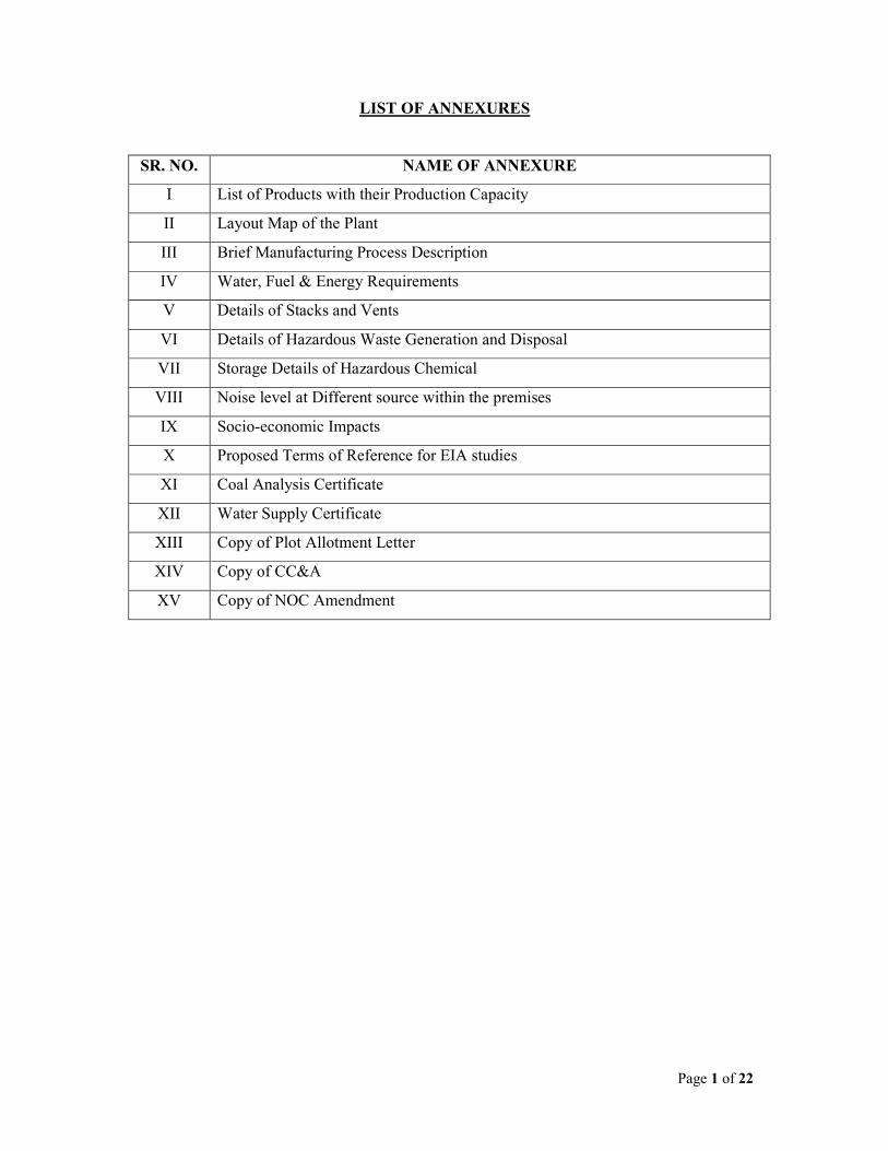
LIST OF ANNEXURES
SR. NO. NAME OF ANNEXURE
I List of Products with their Production Capacity
II Layout Map of the Plant
III Brief Manufacturing Process Description
IV Water, Fuel & Energy Requirements
V Details of Stacks and Vents
VI Details of Hazardous Waste Generation and Disposal
VII Storage Details of Hazardous Chemical
VIII Noise level at Different source within the premises
IX Socio-economic Impacts
X Proposed Terms of Reference for EIA studies
XI Coal Analysis Certificate
XII Water Supply Certificate
XIII Copy of Plot Allotment Letter
XIV Copy of CC&A
XV Copy of NOC Amendment
Page 2 of 22
ANNEXURE-I
_______________________________________________________________________
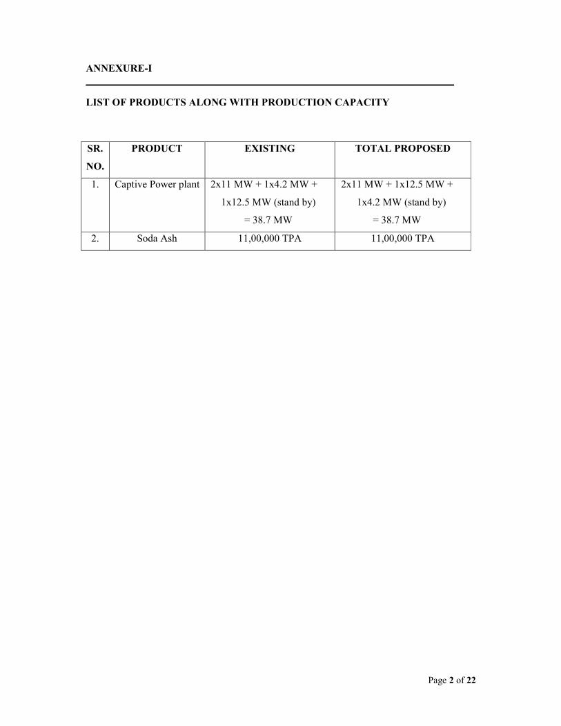
LIST OF PRODUCTS ALONG WITH PRODUCTION CAPACITY
SR.
NO.
PRODUCT EXISTING TOTAL PROPOSED
1. Captive Power plant 2x11 MW + 1x4.2 MW +
1x12.5 MW (stand by)
= 38.7 MW
2x11 MW + 1x12.5 MW +
1x4.2 MW (stand by)
= 38.7 MW
2. Soda Ash 11,00,000 TPA 11,00,000 TPA
Page 3 of 22
ANNEXURE-II
______________________________________________________________________
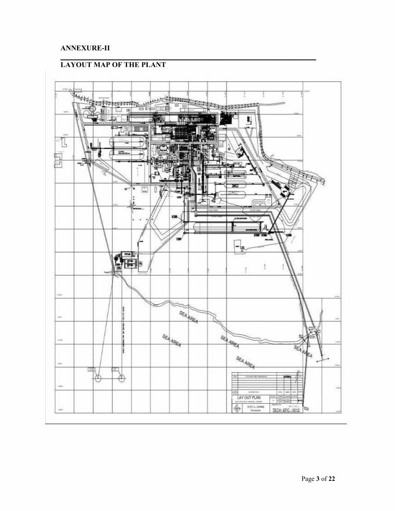
LAYOUT MAP OF THE PLANT
Page 4 of 22
ANNEXURE-III
_______________________________________________________________________
BRIEF MANUFACTURING PROCESS DESCRIPTION
SODA ASH
PROCESS DESCRIPTION:
Soda ash (Na2CO3) is manufactured from limestone, which is mainly composed of CaCO3
(88-90%) and MgCO3 (2-6%). The major impurities present in the mineral are silica (4-6%),
and Al2O3 + Fe2O3 (2%). Deposits of limestone occur in commercially exploitable quantities
at several sites in the Junagadh and Kachchh Districts. Other major raw materials used in the
process are common salt and coke. Common salt, which is produced from seawater in salt
pans through solar evaporation, contains NaCl (94%) and traces of other major metals in
seawater such as Ca (0.2%) and Mg (0.1%). Insoluble impurities namely sediment and sand
particles may constitute upto 0.4%. Coke and lignite used in the process have calorific value
6000 & 3000 Kcal/ Kg respectively while the nonvolatile residue in the fuel is mainly ash
(14%). Details of raw materials required to manufacture 1 t of soda ash are summarised
below:
Material Quantity
Salt 1.7 to1.8 t
Limestone 1.5 to 1.6 t
Coal + lignite 0.5 to 0.6 t
Freshwater 5 to 6 m3
Cooling seawater 140 to 150 m3
Ammonia 3 – 4 kg
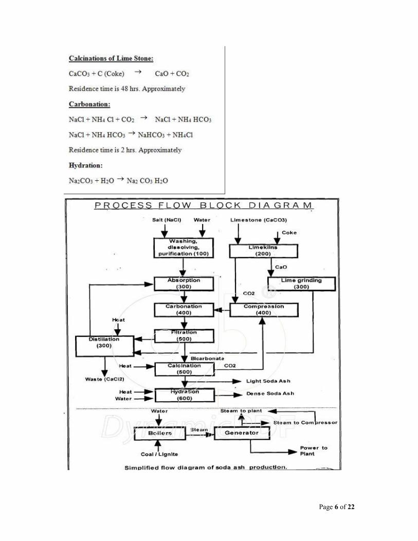
At GHCL, soda ash is produced by a continuous process as illustrated in simplified flow
diagram. The limestone and coke which are used as raw material and fuel respectively are
mixed in a definite proportion and charged to a vertical lime kiln where the mixture is burnt
using combustion air at 1000oC. Here, the limestone is decomposed to lime (CaO) and carbon
dioxide gas. Crude lime thus produced, is grounded and pulverized to an effective size of
0.15 mm. The kiln gas is fed to the compressors for carbonation.
The salt is fed at the rate of 100 - 130 t/h. The oversize salt is transported to the lump
crusher. The salt is then dissolved in raw water to produce the brine solution. Residual
impurities of calcium and magnesium compounds are removed from the brine by treating it
with milk of lime and soda ash. The purified brine is passed through packed towers along

Page 5 of 22
with ammonia that is supplied from the distillation plant to obtain the ammoniated brine. The
ammoniated brine is carbonated by passing through carbonating tower along with
compressed CO2 as well as CO2 recovered from the soda Ash calciner.
Temperature of the tower is controlled by the circulating sea water and chilled water. The
reaction taking place in the carbonating tower is as follows:
NH3 + CO2 + NaCl → NaHCO3 + NH4Cl + Energy
The major product Sodium Bicarbonate (NaHCO3) which is sparingly soluble in water
precipitates while NH4 Cl and other salts remain in mother liquor in the dissolved state. The
bicarbonate Slurry cold as magma is filtered in rotary. Vacuum filters and the bicarbonate
separated is washed with fresh water to remove trace impurities. The crude Bicarbonate thus
obtained is decomposed in a rotary tube steam heated calciner in to Soda Ash (Na2CO3) and
CO2 which is scrubbed, cooled and recycled to the CO2 Compressor. Apart from this the
product is sent to densification and the balance is cooled to ambient temperature and sent for
packing.
The mother liquor rich in NH4Cl and NH4OH is pumped to the Ammonia still where free
Ammonia is removed using gas heat exchangers; the remaining is treated with lime in
prelimer to liberate Ammonia via reaction.
CaO + 2NH4 Cl → CaCl2 + 2NH3 + H2O
The liberated Ammonia is recycled back to process and CaCl2 along with unreacted part of
NaCl, CaCO3 is the final waste.
List of unit operation along with chemical reaction & residence time is given as under.
List of Unit Operation
1. Dissolution of Salt in Water
2. Absorption of Brine
3. Distillation of Ammonia
4. Filtration of Draw Liquor
5. Drying of Monohydrate
Page 6 of 22
Page 7 of 22
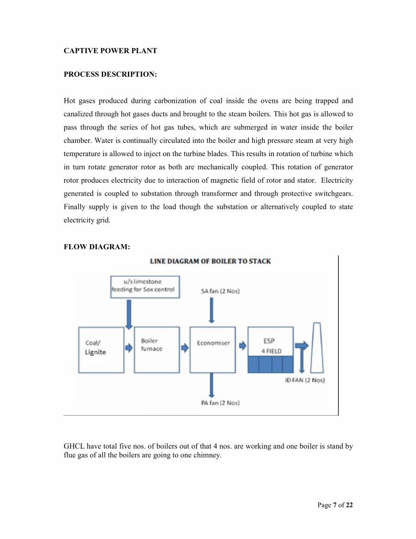
CAPTIVE POWER PLANT
PROCESS DESCRIPTION:
Hot gases produced during carbonization of coal inside the ovens are being trapped and
canalized through hot gases ducts and brought to the steam boilers. This hot gas is allowed to
pass through the series of hot gas tubes, which are submerged in water inside the boiler
chamber. Water is continually circulated into the boiler and high pressure steam at very high
temperature is allowed to inject on the turbine blades. This results in rotation of turbine which
in turn rotate generator rotor as both are mechanically coupled. This rotation of generator
rotor produces electricity due to interaction of magnetic field of rotor and stator. Electricity
generated is coupled to substation through transformer and through protective switchgears.
Finally supply is given to the load though the substation or alternatively coupled to state
electricity grid.
FLOW DIAGRAM:
GHCL have total five nos. of boilers out of that 4 nos. are working and one boiler is stand by
flue gas of all the boilers are going to one chimney.

Page 8 of 22
Details of the boilers are as follows:
1) LB-74, LB-75, LB-76
Type AFBC Boilers
Make M/s Cethar Vessels Limited
Capacity 90 TPH
Pressure 105 Kg/cm2
Temperature 505 ° C
2) LB-77
Type AFBC Boilers
Make Thermax Babcock & Wilcox Ltd
Capacity 90 TPH
Pressure 105 Kg/cm2
Temperature 505 ° C
3) LB-78
Type CFBC Boilers
Make Thermax Babcock & Wilcox Ltd
Capacity 125 TPH
Pressure 105 Kg/cm2
Temperature 505 ° C
4) Turbines
Make BHEL
Capacity 2x11 MW 1x4.2 MW 1x12.5 MW
(Stand by)
Power
Generation
6.6 KV 6.6. KV
Type Single extraction
back pressure
Double extraction
back pressure
Condensing
turbine
Page 9 of 22
ANNEXURE-IV
_______________________________________________________________________
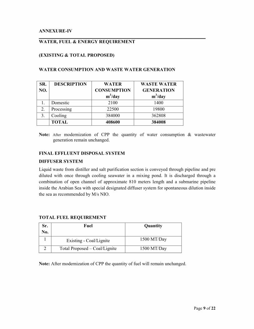
WATER, FUEL & ENERGY REQUIREMENT
(EXISTING & TOTAL PROPOSED)
WATER CONSUMPTION AND WASTE WATER GENERATION
SR.
NO.
DESCRIPTION WATER
CONSUMPTION
m3/day
WASTE WATER
GENERATION
m3/day
1. Domestic 2100 1400
2. Processing 22500 19800
3. Cooling 384000 362808
TOTAL 408600 384008
Note: After modernization of CPP the quantity of water consumption & wastewater
generation remain unchanged.
FINAL EFFLUENT DISPOSAL SYSTEM
DIFFUSER SYSTEM
Liquid waste from distiller and salt purification section is conveyed through pipeline and pre
diluted with once through cooling seawater in a mixing pond. It is discharged through a
combination of open channel of approximate 810 meters length and a submarine pipeline
inside the Arabian Sea with special designated diffuser system for spontaneous dilution inside
the sea as recommended by M/s NIO.
TOTAL FUEL REQUIREMENT
Sr.
No.
Fuel Quantity
1 Existing - Coal/Lignite 1500 MT/Day
2 Total Proposed – Coal/Lignite 1500 MT/Day
Note: After modernization of CPP the quantity of fuel will remain unchanged.
Page 10 of 22
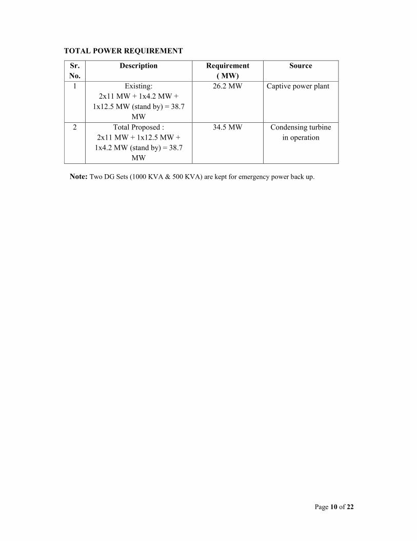
TOTAL POWER REQUIREMENT
Note: Two DG Sets (1000 KVA & 500 KVA) are kept for emergency power back up.
Sr.
No.
Description Requirement
( MW)
Source
1 Existing:
2x11 MW + 1x4.2 MW +
1x12.5 MW (stand by) = 38.7
MW
26.2 MW Captive power plant
2 Total Proposed :
2x11 MW + 1x12.5 MW +
1x4.2 MW (stand by) = 38.7
MW
34.5 MW Condensing turbine
in operation
Page 11 of 22
ANNEXURE-V
_______________________________________________________________________
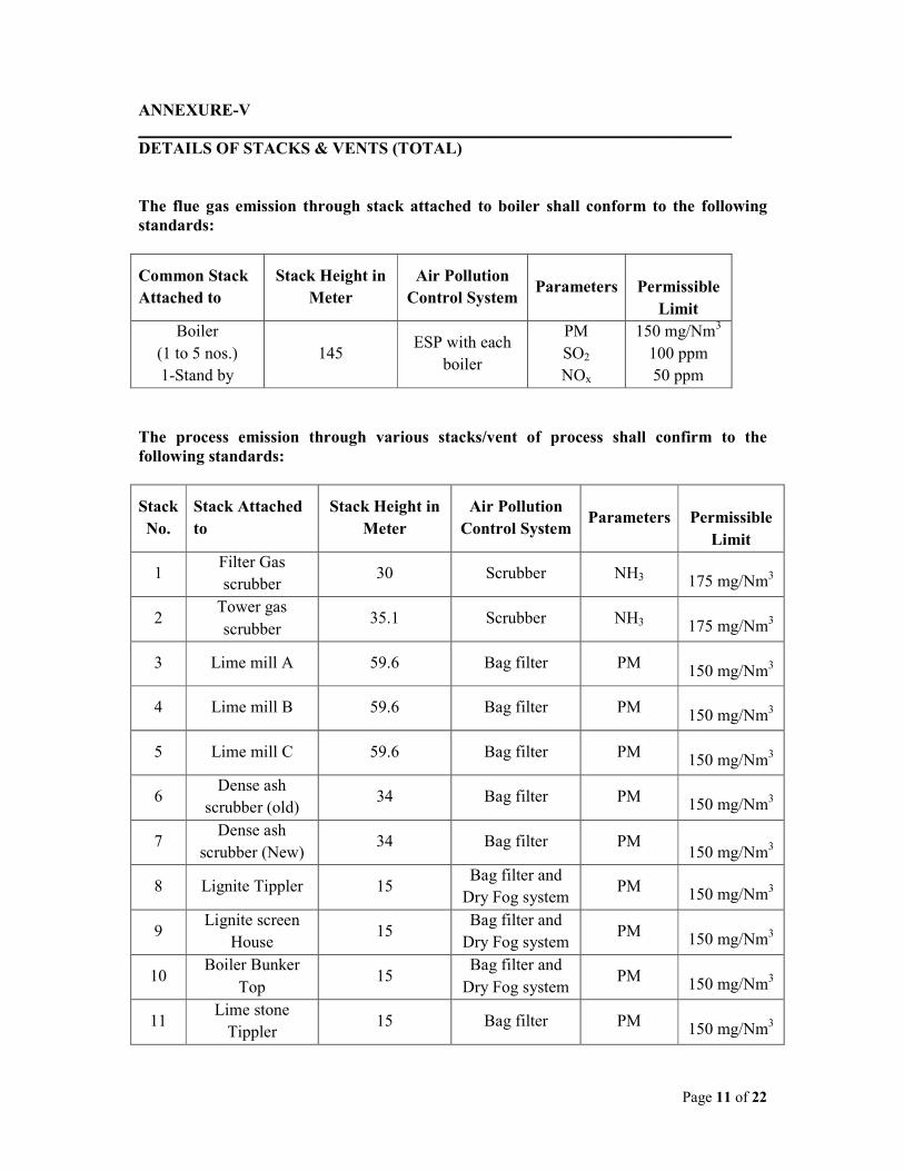
DETAILS OF STACKS & VENTS (TOTAL)
The flue gas emission through stack attached to boiler shall conform to the following
standards:
Common Stack
Attached to
Stack Height in
Meter
Air Pollution
Control System Parameters
Permissible
Limit
Boiler
(1 to 5 nos.)
1-Stand by
145 ESP with each
boiler
PM
SO2
NOx
150 mg/Nm3
100 ppm
50 ppm
The process emission through various stacks/vent of process shall confirm to the
following standards:
Stack
No.
Stack Attached
to
Stack Height in
Meter
Air Pollution
Control System Parameters
Permissible
Limit
1 Filter Gas
scrubber 30 Scrubber NH3
175 mg/Nm3
2 Tower gas
scrubber 35.1 Scrubber NH3
175 mg/Nm3
3 Lime mill A 59.6 Bag filter PM
150 mg/Nm3
4 Lime mill B 59.6 Bag filter PM
150 mg/Nm3
5 Lime mill C 59.6 Bag filter PM
150 mg/Nm3
6 Dense ash
scrubber (old) 34 Bag filter PM
150 mg/Nm3
7 Dense ash
scrubber (New) 34 Bag filter PM
150 mg/Nm3
8 Lignite Tippler 15 Bag filter and
Dry Fog system PM
150 mg/Nm3
9 Lignite screen
House 15
Bag filter and
Dry Fog system PM
150 mg/Nm3
10 Boiler Bunker
Top 15
Bag filter and
Dry Fog system PM
150 mg/Nm3
11 Lime stone
Tippler 15 Bag filter PM
150 mg/Nm3

Page 12 of 22
12 Limestone
screen house 15 Bag filter PM
150 mg/Nm3
13 Lignite feed
Building 15
Bag filter/
Dry Fog system PM
150 mg/Nm3
14 Belt 213 / lime
kiln DSL 15 Bag filter PM
150 mg/Nm3

Page 13 of 22
ANNEXURE-VI
_______________________________________________________________________
DETAILS OF HAZARDOUS WASTE GENERATION AND DISPOSAL
Non-hazardous Waste
SR.
NO.
NAME OF
WASTE
WASTE
CATEGORY
QUANTITY
MODE OF DISPOSAL
1 Used Oil 5.1 40.5 MT/Year Collection, Storage, Transportation
and selling to registered re-refiners
units
2 Used Battery 17 8 MT/Year Collection, Storage, Transportation
and selling to registered re-refiners
units
1 Fly Ash -- 88560 MT/Yea
Bricks manufacturing plant within
factory premises & sell to National
Highway Authority of India (NHAI)
for road construction.

Page 14 of 22
ANNEXURE-VII
_______________________________________________________________________
STORAGE & HANDLING DETAILS OF HAZARDOUS CHEMICALS
GHCL is handling Ammonia and it is used in process in small quantity Two storage tank for
storing Liquid Ammonia with licensed capacity of 75 MT of each has been provided. The
Inspector of Explosives, Government of Gujarat, approves the tank construction and layout.
• Out of Two tanks one tank is kept always empty. In case of any emergency, the liquid
Ammonia can be transferred from one tank to another.
• The tank is designed for the pressure higher than operating pressure and has been
fabricated by the explosive Department, approved manufacturer. The controller of the
Explosives is inspecting this and they are providing Approvals.
• All the Nozzles are provided with two isolation valves.
• Each tank is provided with two safety release valves.
• Specially designed excess flow prevention valves have been provided on both inlet and
outlet Nozzles of each tank.
• Ammonia can be easily absorbed in the water. Specially designed Fire Hydrant System
as per the Guideline of Tariff Advisory Committee is provided. This has got special jets
water to the height of 75 meters.
• All the electrical Lighting and fittings are of flameproff construction to avoid any
sparking.
• The operating staff is well trained to face any eventualities. Gas mark with breathing air
sets is readily available.
• Special task force has been formed to tackle any hazard.
• Regularly third party Safety Audits.
• GHCL has adopted fire hydrant system. It consists of network of 3.5 KM of hydrant
System and is governed by various codes and guidelines from Tariff Advisory
Committee.
SR.
NO.
NAME OF CHEMICAL TYPE OF
HAZARD
MODE OF
STORAGE
STORED
QUANTITY
1 Ammonia Toxic MS Tank
75 MT – Licensed
capacity
(2 Nos.)

Page 15 of 22
• Emergency organization has been formed to handle any possible hazards. The duties of
each personnel have been properly written.
• Assembly points are fixed. Provisions of both side roads have been made.
• Training and rehearsals are regular features.
• A booklet on the Ammonia has been prepared and distributed to the all-surrounding
areas to overcome any eventuality.

Page 16 of 22
ANNEXURE-VIII
_______________________________________________________________________
NOISE LEVEL AT DIFFERENT SOURCE WITHIN PREMISES
Various Location Noise Level are monitored and its results are given below.
Sr.
No.
Location
Noise Levels in dB (A)
1st
Monitoring 2nd
Monitoring
3rd
Monitoring
Day Night Day Night Day Night
1 Main Gate 73 62 78 68 80 65
2 HR building 68 58 72 59 67 58
3 Canteen 75 62 77 63 73 60
4 STP Plant
Colony-1
70 61 74 65 72 62
5 Boiler Area 71 68 76 66 79 71
6 Turbine area 82 80 81 83 85 84
7 Colony-2 67 62 71 62 70 64
8 Coal Storage
area
68 64 72 63 77 66
9 Pump Station 77 70 77 67 79 72
Following are the various remedial measured applied to reduce Noise Pollution.
Sr.
No.
Source of Pollution Remedial Measures
1 CO2 Compressors Noise Hood in the form of closed
enclosures
2 Kiln Blowers VFD & enclosures has been provided
3 Vacuum Pumps Enclosures has been provided
be attached to exiting coke oven batteries.
Page 17 of 22
ANNEXURE-IX
_______________________________________________________________________
SOCIO - ECONOMIC IMPACTS
1) EMPLOYMENT OPPORTUNITIES
During operation phase, skilled and unskilled manpower will be needed. This will
temporarily increase the employment opportunity. Secondary jobs are also bound to be
generated to provide day-to-day needs and services to the work force. This will also
temporarily increase the demand for essential daily utilities in the local market. The
manpower requirement for the proposed modernization is expected to generate some
permanent jobs and secondary jobs for the operation and maintenance of plant. This will
increase direct / indirect employment opportunities and ancillary business development to
some extent for the local population. This phase is expected to create a beneficial impact on
the local socio-economic environment.
2) INDUSTRIES
During operation of the project, the required skilled and unskilled laborers will be utilized
maximum from the local area. The increasing industrial activity will boost the commercial
and economical status of the locality, to some extent.
3) PUBLIC HEALTH
During operation period, workers will be provided with basic amenities like safe water
supply, low cost sanitation facilities, first aid, required personal protective equipment, etc.
Otherwise, there could be an increase in diseases related to personal hygiene. The company
will regularly examine, inspects and tests its emission from sources to make sure that the
emission is below the permissible limit. Hence, there will not be any significant change in the
status of sanitation and the community health of the area, as sufficient measures have been
taken and proposed under the EMP.
4) TRANSPORTATION AND COMMUNICATION
Since the proposed factory is having proper linkage for the transport and communication, the
development of this project will not cause any additional impact. In brief, as a result of the
modernization there will be no adverse impact on sanitation, communication and community
health, as sufficient measures have been proposed to be taken under the EMP. The proposed
modernization is not expected to make any significant change in the existing status of the
socio - economic environment of this region.
Page 18 of 22
ANNEXURE-X
_______________________________________________________________________
PROPOSED TERMS OF REFERENCE FOR EIA STUDIES
The Environmental Impact Assessment of the project shall examine the project’s potential
negative and positive environmental impacts and shall recommend any measure needed to
prevent, minimize, mitigate or compensate for adverse impacts and improve environmental
performance of the schemes. It should prevent future liabilities or expensive alternatives in
the project. Impact assessment requires as a sound knowledge and understanding of the
baseline situation and of the autonomous development situation.
The conduct of the assessment will be governed and content of the report will be specified by
following legislation and other relevant regulation, if applicable.
• Environmental Protection Act – 1986
• Water (Prevention and Control) of Pollution Act – 1974
• Air (Prevention and Control) of Pollution Act – 1981
• Hazardous Waste (Management & Handling) Amended Rules - 2003
• Environmental Impact Assessment Notification – 2006
METHODOLOGIES FOR EIA
Taking into consideration proposed project activities and guidelines, an area of 10 km radius
from the center of the project has been selected and is designated as the study area for the
purpose of rapid EIA studies.
BASE LINE CONDITION
The samples of ambient air, ground and surface water and soil are collected and analyzed as
per the standard methods for establishing the baseline data and to determine the impact of
proposed activity on the same.
AMBIENT AIR ENVIRONMENT
The air environment around the plant was studied by setting up eleven locations within the
study area of 10 Km radius from the project site and collection and monitoring the site
specific meteorological data, viz. wind speed, wind direction, humidity, rainfall and ambient
temperature was carried out. Design of network for ambient air quality monitoring locations
is based on guidelines provided by CPCB. The ambient air samples were collected and
Page 19 of 22
analyzed for SPM, RSPM, SO2, Nox, HCl and Cl for identification, prediction, evaluation
and assessment of potential impact on ambient air environment.
GROUND AND SURFACE WATER ENVIRONMENT
The water required for domestic and industrial use is being made available from surface
water. Hence, to assess the physico-chemical quality of the water, a number of water samples
were collected and analyzed for pollution parameters viz., pH, TDS, Turbidity, BOD3, COD,
Fluorides, Chlorides, Sulphates, Nitrates, Ammonical Nitrogen, Hardness, Alkalinity, Oil &
Grease and some heavy metals in order to find out the contamination, if any.
NOISE ENVIRONMENT
Noise pollution survey was conducted in the study zone. The anticipated noise sources were
industrial activities, which are likely to be increased due to proposed activity. Noise levels
were also recorded in surrounding villages for evaluating general scenario of the study area.
Hourly equivalent sound levels (Leq) were also recorded for calculating Day and Night noise
levels in the surrounding villages.
SOIL ENVIRONMENT
Soil sampling and analysis was carried out to assess physico-chemical characteristics of the
soils and delineate existing cropping pattern, existing land use and topography, within the
study area.
BIOLOGICAL ENVIRONMENT
Keeping in view, the importance of biological component of total environment due to the
proposed project, biological characterization of terrestrial and aquatic environments, changes
in species diversity of flora and fauna in terrestrial as well as aquatic systems were studied for
impact analysis due to proposed project activity, if any.
SOCIO-ECONOMIC ENVIRONMENT
Demographic and related socio-economic data was collected from census handbook to assess
socio-economic status of the study area. Assessment of impact on significant historical,
cultural, and archeological sites/places in the area and economic and employment benefit
arisen out from the project is given special attention.
Page 20 of 22
IDENTIFICATION OF POLLUTION SOURCE
Detailed study of manufacturing process for existing production scenario and post
modernization scenario is carried out along with input and output of materials, water, and
wastewater as well as infrastructure facilities available.
EVALUATION OF POLLUTION CONTROL AND ENVIRONMENTAL
MANAGEMENT SYSTEM
The qualitative and quantitative analysis of various pollution sources as well as evaluation of
pollution control system is carried out.
EVALUATION OF IMPACT
A comprehensive evaluation of environmental impact with reference to proposed
modernization activities is carried out.
PREPARATION OF ENVIRONMENTAL MANAGEMENT PLAN
A comprehensive Environmental Management Plan has been prepared covering all the
aspects of pollution prevention measures, Air and Water Pollution Control measures,
Hazardous Waste Management, Environmental Surveillance and Environmental Management
Plan.
Page 21 of 22
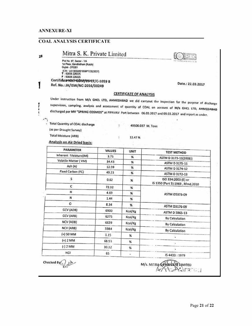
ANNEXURE-XI
_______________________________________________________________________
COAL ANALYSIS CERTIFICATE

Page 22 of 22
ANNEXURE-XII
_______________________________________________________________________
WATER SUPPLY CERTIFICATE
Related Documents