M-A5D35 Linux-Ready Cortex-A5 System on Module Hardware Guide Version: 1.0 2017 July

Welcome message from author
This document is posted to help you gain knowledge. Please leave a comment to let me know what you think about it! Share it to your friends and learn new things together.
Transcript

M-A5D35
Linux-Ready Cortex-A5
System on Module
Hardware Guide
Version: 1.0
2017 July

M-A5D35 User Guide
ARTILA 2
Trademarks
The Artila logo is a registered trademark of Artila Inc. All other trademarks or
registered marks in this manual belong to their respective manufacturers.
Disclaimer
Information in this document is subject to change without notice and does not
represent a commitment on the part of Artila.
Artila provides this document as is, without warranty of any kind, either expressed
or implied, including, but not limited to, its particular purpose. Artila reserves the
right to make improvements and/or changes to this manual, or to the products
and/or the programs described in this manual, at any time.
Information provided in this manual is intended to be accurate and reliable.
However, Artila assumes no responsibility for its use, or for any infringements on
the rights of third parties that may result from its use.
This product might include unintentional technical or typographical errors.
Changes are periodically made to the information herein to correct such errors,
and these changes are incorporated into new editions of the publication.

M-A5D35 User Guide
ARTILA 3
Document Amendment History
Revision Date Remark
V 0.1 2017 Jan. Initial
V 1.0 2017 Jul. Hardware Guide

M-A5D35 User Guide
ARTILA 4
Table of Contents
1. Introduction .................................................................................................. 5
1.1 Features .............................................................................................. 5
1.2 Specifications (Hardware) .................................................................... 5
1.3 Specifications (Software) ..................................................................... 7
1.4 Packing List ......................................................................................... 9
1.5 Optional ............................................................................................... 9
2. SAMA5D35: ARM Cortex-A5 MPU ............................................................... 10
2.1 SAMA5D35 Features ........................................................................... 10
2.2 SAMA5D35 Block Diagram .................................................................. 13
3. Layout ........................................................................................................... 14
3.1 Outlook ................................................................................................ 14
3.2 Dimensions .......................................................................................... 14
4. Pin Assignment and Definitions.................................................................. 15
4.1 Block Diagram ..................................................................................... 15
4.2 Connector Information ......................................................................... 15
4.3 Connector and PIN definition ............................................................... 15
4.3.1 Connector (CN1) ................................................................................. 16
4.3.2 Connector (CN2) ................................................................................. 17
5. Starter Kit...................................................................................................... 18
5.1 Features .............................................................................................. 18
5.2 I/O ports............................................................................................... 19
6. Initial Operation ............................................................................................ 20
6.1 Using Default Linux file system ............................................................ 20
6.2 Install Software Package ..................................................................... 20

M-A5D35 User Guide
ARTILA 5
1. Introduction
M-A5D35 is highly integrated, compact, low power consumption, the Linux-Ready
ARM Cortex-A5 System-on-Module.
It provides an ideal building block that easily integrates with a wide range of target
markets, such as industrial control, automation gateway and other applications.
Linux 4.9.X OS is pre-installed in the flash disk of M-A5D35 and many powerful utility
programs are also included. M-A5D35 is ready to drop in your design to save your
time in software porting and hardware debug.
1.1 Features
� ATSAMA5D35 ARM Thumb Processor with 536MHz, Memory Management Unit
� 32-KByte Data Cache and 32-KByte Instruction Cache
� 512MB SDRAM LPDDR2, 8GB eMMC Flash, 8MB DataFlash
� Dual Ethernet interface:
- One 10/100Mbps Ethernet with MAC/PHY and transformer,
- One Gigabit Ethernet with MAC/PHY and transformer
� Two USB 2.0 Hi-speed (480Mbps) Host Ports
� Multimedia Card Interface for SDHC memory card
� Four UARTs with hardware and software flow control
� On board Real Time Clock with Lithium battery
� I2C bus
� I2S bus
� 21 Programmable Digital I/O Port
� Serial Peripheral Interface (SPI) Ports
� Linux 4.4.X OS
1.2 Specifications (Hardware)
� CPU / Memory
� CPU: ATMEL ATSAMA5D35
� ARM Cortex-A5 Thumb Processor with Memory Management Unit (MMU)
� Clock: 536MHz
� SDRAM: 512MB, LPDDR2
� Flash: 8G eMMC Flash and 8MB DataFlash

M-A5D35 User Guide
ARTILA 6
� Network
� Ethernet: 10/100Mbps/Gigabit with MAC/PHY and Transformer
� PHY: Micrel KSZ8081RNAIA(10/100Mbps)
� LAN port Signal: ETH1_TXO0+, ETH1_TXO0-, ETH1_RXI0+, ETH1_RXI0-
� PHY: Micrel KSZ9031RNXCA (Gigabit)
� GLAN port Signal: GETH0_TX1+,GETH0_TX1-, GETH0_RX1+, GETH0_RX1-,
GETH0_TX2+,GETH0_TX2-, GETH0_RX2+, GETH0_RX2-
� Transformer: 1.5 KV isolation
� USB Port
� Host: USB 2.0 Hi speed (480Mbps) Host x2
� Signal: USB Host_1 Data+, USB Host_2 Data-, USB Host_2 Data+,
USB Host_2 Data-
� Device: DDP (data+), DDM (data-), UDIO (I/O)
� UART
� Four Universal Asynchronous Receiver and Transmitter
� Data Bits: 5 to 9 bits
� Parity: None, Even, Odd, Mark, Space
� Stop: 1, 1.5, 2 bits
� Baud Rate: Up to 921.6 Kbps
� Flow Control: RTS/CTS, XON/XOFF, None
� RS-485 Driver Control Signal (PD16,PB27,PE24,PE17)
� Signal Level: CMOS/3.3V compatible
� COM1: TXD, RXD, RTS (Software configurable RS-232/485 mode)
� COM2: TXD, RXD, RTS, CTS (Software configurable RS-232/485 mode)
� COM3: TXD, RXD, RTS, CTS (Software configurable RS-232/485 mode)
� COM4: TXD, RXD, RTS, CTS (Software configurable RS-232/485 mode)
� Programmable DIO
� 63 General Purpose I/O can be programmable as digital input or output
� Signal Level: CMOS/TTL Compatible
� Digital Input:
- Low level: -0.3V min / +0.8V max
- High level: +2.0V min / +3.6V max
� Digital Output:
- Low level: +0.4V max @ 8mA
- High level: +2.9V min @ 8mA
� Signal: GPIO – PA Number, PB Number, PC Number, PD Number,
PE Number

M-A5D35 User Guide
ARTILA 7
� SPI (Serial Peripheral Interface)
� Two chip Selects with external decoder
� Three wires signals: MISO, MOSI and CLK clock
� Signal: MISO, MOSI, CLK, CS0, CS1, CS2, CS3
� Supported Device: ATMEL DataFlash
� Predefine Pins
� Reset Button (CN1, pin#35, BTNRST# ), input
� Buzzer (CN1, pin#29, PD6/TIOB0), output
� System Ready LED (CN1, pin#19, PD5/TIOA0), output
� LAN Activity LED (CN1, pin#14, GLAN ACTLED1#, CN1 Pin#12 ELAN
ACTLED2#), output
� Debug Port
� Signal: Debug_TX, Debug_RX
� Connector: JP1
� Power
� Input: 4.75 to 5.25VDC (5V nominal)
� Consumption: 0.75W
1.3 Specifications (Software)
� Operation System
� Linux kernel 4.9.x
� Supports bootup from eMMC or SD card
� Boot Loader: Barebox
� File System: EXT4
� M-A5D35 uses ETX4 file system for the built-in flash memory disk.
� The files system is stored at NAND flash memory.
� Software Development
� Toolchain: gcc 6.2.0xx + glibc 2.24xx
� Supports in-place C/C++ code compilation
� Package Management
� Package repository: Artila self-maintained repository
� Command: Using standard apt-get command
� Popular Packages
� Web server: Apache/Nginx/Lighttpd
� Database: MySQL/SQLite3/PostgreSQL
� Script Language: PHP/Python/Perl/NodeJS
� Text editor: vim/nano/sed
� Administration: Webmin
M-A5D35 User Guide
ARTILA 8
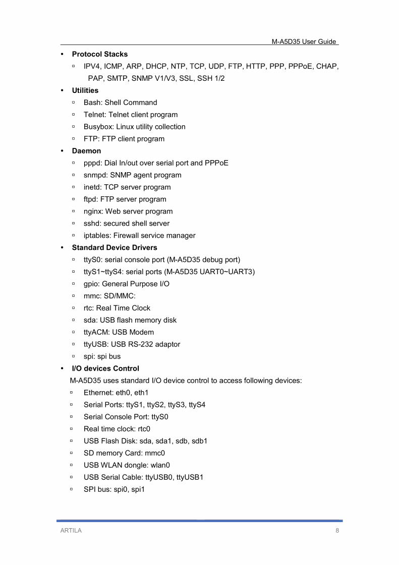
� Protocol Stacks
� IPV4, ICMP, ARP, DHCP, NTP, TCP, UDP, FTP, HTTP, PPP, PPPoE, CHAP,
PAP, SMTP, SNMP V1/V3, SSL, SSH 1/2
� Utilities
� Bash: Shell Command
� Telnet: Telnet client program
� Busybox: Linux utility collection
� FTP: FTP client program
� Daemon
� pppd: Dial In/out over serial port and PPPoE
� snmpd: SNMP agent program
� inetd: TCP server program
� ftpd: FTP server program
� nginx: Web server program
� sshd: secured shell server
� iptables: Firewall service manager
� Standard Device Drivers
� ttyS0: serial console port (M-A5D35 debug port)
� ttyS1~ttyS4: serial ports (M-A5D35 UART0~UART3)
� gpio: General Purpose I/O
� mmc: SD/MMC:
� rtc: Real Time Clock
� sda: USB flash memory disk
� ttyACM: USB Modem
� ttyUSB: USB RS-232 adaptor
� spi: spi bus
� I/O devices Control
M-A5D35 uses standard I/O device control to access following devices:
� Ethernet: eth0, eth1
� Serial Ports: ttyS1, ttyS2, ttyS3, ttyS4
� Serial Console Port: ttyS0
� Real time clock: rtc0
� USB Flash Disk: sda, sda1, sdb, sdb1
� SD memory Card: mmc0
� USB WLAN dongle: wlan0
� USB Serial Cable: ttyUSB0, ttyUSB1
� SPI bus: spi0, spi1
M-A5D35 User Guide
ARTILA 9
� Default Setting
� IP Default setting:
� eth0: DHCP
� eth1: 192.168.2.127 (Netmask: 255.255.255.0)
� ssh Login: root
� Password: root
� Terminal type: VT100
1.4 Packing List
� M-A5D35: Linux-ready Cortex-A5 536MHz SoM (System on Module) with 512MB
SDRAM, 8GB eMMC Flash
1.5 Optional
Accessory
� DK-35A (36-DK35A-000): DIN RAIL Mounting Kit
� PWR-12V-1A (31-62100-000): 110~240VAC to 12VDC 1A Power Adaptor
Starter Kit
� CB-Matrix-700 (M-A5D35 included), Linux
� 91-PHDF9-050: Console Cable (4Pin header to DB9 Female, 50cm)

M-A5D35 User Guide
ARTILA 10
2. SAMA5D35: ARM Cortex-A5 MPU
SAMA5D3 series is a high-performance, power-efficient embedded MPU based on
the ARM Cortex-A5 processor, achieving 536 MHz with power consumption levels
below 0.5 mW in low-power mode. The device features a floating point unit for
high-precision computing and accelerated data processing, and a high data
bandwidth architecture. It integrates advanced user interface and connectivity
peripherals and security features. Detail information, please refer to
http://www.microchip.com/wwwproducts/en/ATSAMA5D35
2.1 SAMA5D35 Features
Core
� ARM Cortex-A5 Processor with ARMv7-A Thumb-2 Instruction Set
� CPU Frequency up to 536 MHz
� 32 Kbyte Data Cache, 32 Kbyte Instruction Cache, Virtual Memory System
Architecture (VMSA)
� Fully Integrated MMU and Floating Point Unit (VFPv4)
Memories
� One 160 Kbyte Internal ROM Single-cycle Access at System Speed, Embedded
Boot Loader: Boot on 8-bit
� NAND Flash, SDCard, eMMC, serial DataFlash, selectable Order
� One 128 Kbyte Internal SRAM, Single-cycle Access at System Speed
� High Bandwidth 32-bit Multi-port Dynamic RAM Controller supporting 512 Mbyte 8
bank 32-bit or 2x16-bit
� SDRAM devices
� Independent Static Memory Controller with datapath scrambling and SLC/MLC
NAND Support with up to 24-bit
� Error Correction Code (PMECC)
System running up to 166 MHz
� Reset Controller, Shutdown Controller, Periodic Interval Timer, Watchdog Timer
and Real-time Clock
� Boot Mode Select Option, Remap Command
� Internal Low-power 32 kHz RC Oscillator and Fast 12 MHz RC Oscillator
� Selectable 32768 Hz Low-power Oscillator and 12 MHz Oscillator
� One 400 to 1000 MHz PLL for the System and one PLL at 480 MHz optimized for
USB High Speed
� 39 DMA Channels including two 8-channel 64-bit Central DMA Controllers

M-A5D35 User Guide
ARTILA 11
� 64-bit Advanced Interrupt Controller
� Three Programmable External Clock Signals
� Programmable Fuse Box with 256 fuse bits (of which 192 are available for users)
Low Power Management
� Shutdown Controller
� Battery Backup Registers
� Clock Generator and Power Management Controller
� Very Slow Clock Operating Mode, Software Programmable Power Optimization
Capabilities
Peripherals
� LCD TFT Controller with Overlay, Alpha-blending, Rotation, Scaling and Color
Space Conversion
� ITU-R BT. 601/656 Image Sensor Interface
� Three HS/FS/LS USB Ports with On-Chip Transceivers
� One Device Controller
� One Host Controller with Integrated Root Hub (3 Downstream Ports)
� One 10/100/1000 Mbps Gigabit Ethernet Media Access Controller (GMAC) with
IEEE1588 support
� One 10/100 Mbps Ethernet Media Access Controller (EMAC)
� Two CAN Controllers with 8 Mailboxes, fully compliant with CAN 2.0 Part A and
2.0 Part B
� Softmodem Interface
� Three High Speed Memory Card Hosts (eMMC 4.3 and SD 2.0)
� Two Master/Slave Serial Peripheral Interfaces
� Two Synchronous Serial Controllers
� Three Two-wire Interface up to 400 Kbit/s supporting I2C Protocol and SMBUS
� Four USARTs (ISO7816, IrDA , RS-485, SPI, Manchester and Modem Modes)
� Two UARTs
� One DBGU
� Two 3-channel 32-bit Timer/Counters
� One 4-channel 16-bit PWM Controller
� One 12-channel 12-bit Analog-to-Digital Converter with Resistive Touchscreen
function

M-A5D35 User Guide
ARTILA 12
Safety
� Power-on Reset Cells
� Independent Watchdog
� Main Crystal Clock Failure Detection
� Register Write Protection
� SHA: Supports Secure Hash Algorithm (SHA1, SHA224, SHA256, SHA384,
SHA512)
� Memory Management Unit
Security
� TRNG: True Random Number Generator
� Encryption Engine
� AES: 256-bit, 192-bit, 128-bit Key Algorithm, Compliant with FIPS PUB 197
Specifications
� DES: Two-key or Three-key Algorithms, Compliant with FIPS PUB 46-3
Specifications
� Atmel Boot Solution
I/O
� Five 32-bit Parallel Input/Output Controllers
� 160 I/Os
� Input Change Interrupt Capability on Each I/O Line, Selectable Schmitt Trigger
Inpu
� Individually Programmable Open-drain, Pull-up and Pull-down Resistor,
Synchronous Output, Filtering
� Slew Rate Control on High Speed I/Os
� Impedance Control on DDR I/Os

M-A5D35 User Guide
ARTILA 13
2.2 SAMA5D35 Block Diagram

M-A5D35 User Guide
ARTILA 14
3. Layout
3.1 Outlook
Top View
Bottom View
3.2 Dimensions
(unit:mm)

M-A5D35 User Guide
ARTILA 15
4. Pin Assignment and Definitions
4.1 Block Diagram
4.2 Connector Information
� 50pin dual raw female header
� Pitch: 1.27mm
� Current Rating: 1Amp
4.3 Connector and PIN definition
The M-A5D35 exposes a pair of 50pin connector, here is the connector information
and pin definition.

M-A5D35 User Guide
ARTILA 16
4.3.1 Connector (CN1)
CN1 includes signals: USB, GLAN, LAN, SPI, GPIO
CN1
GLAN_RX2- 1 2 GLAN_RX2+
GLAN_TX2- 3
4 GLAN_TX2+
GLAN_RX1- 5
6 GLAN_RX1+
GLAN_TX1- 7
8 GLAN_TX1+
GLAN_GND 9
10 GLAN_GND
LAN_TX+ 11
12 LAN_LED
LAN_TX- 13
14 GLAN_LED
LAN_RX+ 15
16 Debug_TX
LAN_RX- 17
18 Debug RX
(PD5) 19
20 (PE31) / IRQ
USB Device Data- 21
22 USB Device Data+
USB Host_1 Data+ 23
24 USB Host_2 Data+
USB Host_1 Data- 25
26 USB Host_2 Data-
(PD7) 27
28 PC22 or SPI_MISO
(PD6) 29
30 PC23 or SPI_MOSI
N/A 31
32 PC24 or SPI_CLK
N/A 33
34 PC25 or SPI_CS0
RST#1 35
36 PC26 or SPI_CS1
(PC29) 37
38 PC27 or SPI_CS2
(PC30) 39
40 PC28 or SPI_CS3
(PA30) 41
42 (PD19)
(PA31) 43
44 (PD20)
(PD30) 45
46 (PD21)
GND 47
48 GND
+5V 49 50 +5V

M-A5D35 User Guide
ARTILA 17
4.3.2 Connector (CN2)
CN2 includes signals: CAN, UART, VBAT, I2C, I2S, SD card
CN2
BAT_In 1 2 +5V
GND 3
4 GND
PD14 or CAN0_RXD 5
6 PB14 or CAN1_RXD
PD15 or CAN0_TXD 7
8 PB15 or CAN1_TXD
PD16 or COM1_RTS 9
10 PB26 or COM2_CTS
PD17 or COM1_RXD 11
12 PB27 or COM2_RTS
PD18 or COM1_TXD 13
14 PB28 or COM2_RXD
PE23 or COM3_CTS 15
16 PB29 or COM2_TXD
PE24 or COM3_RTS 17
18 PE16 or COM4_CTS
PE25 or COM3_RXD 19
20 PE17 or COM4_RTS
PE26 or COM3_TXD 21
22 PE18 or COM4_RXD
PA18 or I2C_Data 23
24 PE19 or COM4_TXD
PA19 or I2C_CLK 25
26 PC16 or I2S_TX_CLK
PD0 or SD_CMD 27
28 PC17 or I2S_TX_Sync
PD1 or SD_Data0 29
30 PC18 or I2S_TX_Data
PD2 or SD_Data1 31
32 PC19 or I2S_RX_CLK
PD3 or SD_Data2 33
34 PC20 or I2S_RX_Sync
PD4 or SD_Data3 35
36 PC21 or I2S_RX_Data
PD9 or SD_CLK 37
38 PD31 or Audio
PA27 or SD_CD 39
40 PA0
PA20 41
42 PA1
PA21 43
44 PA2
PA22 45
46 PA3
PA23 47
48 PA26
WDT Signal 49 50 NA
Note: pin7 also can be use as COM_CTS

M-A5D35 User Guide
ARTILA 18
5. Starter Kit
CB-Matrix-700 is an evaluation board for M-A5D35. It serves as a complete
development kit for evaluation and application development purposes.
5.1 Features
� Support M-A5D35 System On Module via two 50pins connector
� One Gigabit Ethernet port (RJ45)
� One 10/100Mbps Ethernet port (RJ45)
� Two USB 2.0 high speed (480Mbps) Host ports
� Four software configurable RS-232/485 serial ports
� One USB console port
� One microSD socket reserved
� Watch-Dog Timer
� Real Time Clock
� Buzzer
� +9VDC to +48VDC power input
� Pre-installed the Linux kernel 4.4.X and file system
� GNU toolchain available on Artila’s self-maintained repository
� Wall-mounting installation, Optional DIN-rail mounting kit
More comprehensive information can be found in the following documents and
resources at http://www.artila.com/en/p_matrix.html

M-A5D35 User Guide
ARTILA 19
5.2 I/O ports
Top View
Bottom View

M-A5D35 User Guide
ARTILA 20
6. Initial Operation
This guide provides initial information about how to use the CB-Matrix-700 starter kit
to start up M-A5D35 and initial operation with the supplied boot devices.
6.1 Using Default Linux file system
1. Power on M-A5D35, Console port automatically emulates an USB CDC/ACM
compatible serial device. (Both USB console & Debug console port)
2. Plug the console cable from console port to PC:
- USB console port (CN4), Micro-USB
- Debug console port (JP3), 4pin header. Refer to attached console cable.
3. Download any PC terminal program. Artila suggests to use “Putty”.
4. The serial communication parameters are: 115200, N81, VT100.
5. The identifier name on PC,
- On Linux system, the serial port name looks like ttyACM0, ttyACM1, etc.
- On OSX system, the serial port name looks like tty.usbmodem1421,
tty.usbmodem1422, etc.
- On Windows system, the serial port name looks like COM3, COM4, etc.
6.2 Install Software Package
M-A5D35/CB-Matrix-700 supports standard apt (Advanced Package Tool) package
management utility for installation, upgrade and remove software packages.
Artila supports apt configuration file also. You may have software support at
http://www.artila.com/download/A5D35/Linux/
Related Documents