LIGHT TOWER MLT4060 & MLT4080 OPERATING/PARTS MANUAL

Welcome message from author
This document is posted to help you gain knowledge. Please leave a comment to let me know what you think about it! Share it to your friends and learn new things together.
Transcript
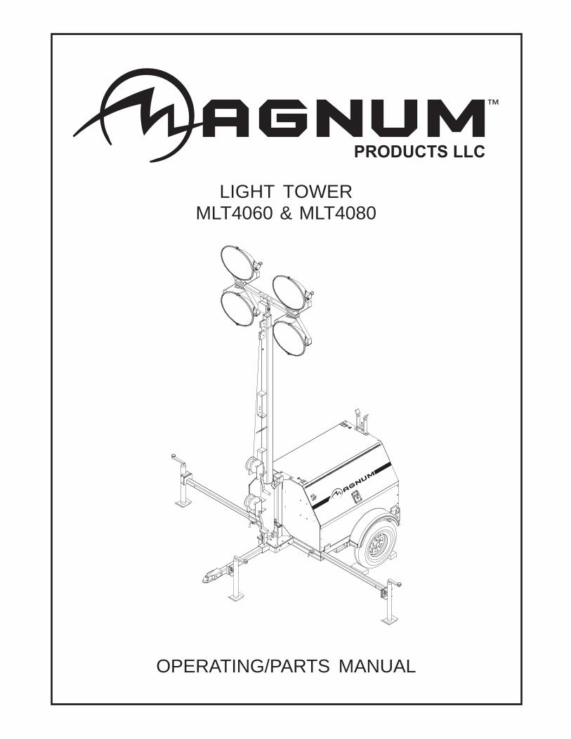
LIGHT TOWERMLT4060 & MLT4080
OPERATING/PARTS MANUAL

2
INTRODUCTION
This manual provides information and procedures to safely operate and maintain the light tower and generator. Foryour own safety and protection from physical injury, carefully read, understand, and observe the safety instructionsdescribed in this manual. The information contained in this manual was based on machines in production at thetime of publication. Magnum Products LLC reserves the right to change any portion of this information withoutnotice.
DO NOT MODIFY or use this equipment for any application other than which it was designed for.
Magnum Products LLC recommends that a trained and licensed professional perform all electrical wiring and testingfunctions. Any wiring should be in compliance with the United States National Electric Code (NEC), state and localcodes and Occupational Safety and Health Association (OSHA) guidelines.
Keep a copy of this manual with the unit at all times. Additional copies are available from Magnum Products LLC, orcan be found at www.m-p-llc.com. An engine operators manual was also supplied with the unit at the time ofshipment from the factory. The manual provides detailed operation and maintenance procedures for the engine.Additional copies of the engine operators manual are available from the engine manufacturer.
MAGNUM PRODUCTS LLC215 Power Drive • Berlin, WI 54923
U.S.A.Phone: 920-361-4442
Fax: 920-361-4416Toll Free: 1-800-926-9768
www.m-p-llc.com
WHEN CALLING FOR PARTS OR TECHNICAL SERVICE INFORMATION,PLEASE HAVE YOUR UNIT MODEL NUMBER AND SERIAL NUMBER READY.
CALIFORNIA PROPOSITION 65 WARNING:Diesel engine exhaust and some of its constituents are known to the stateof California to cause cancer, birth defects and other reproductive harm.
WARNING
Engine Make:
Engine Serial Number:
Engine Model Number:
Generator Make:
Generator Model Number:
Generator Serial Number:
Unit Model Number:
Unit Serial Number:
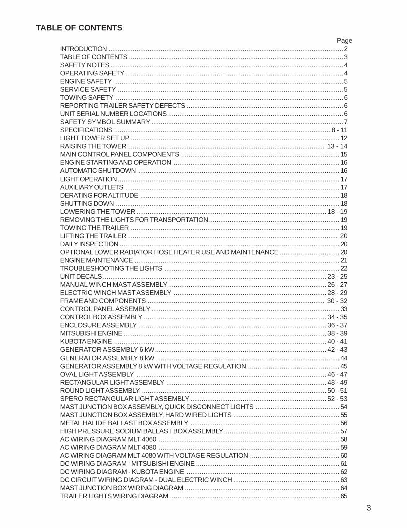
TABLE OF CONTENTS
PageINTRODUCTION ..............................................................................................................................2TABLE OF CONTENTS ...................................................................................................................3SAFETY NOTES.............................................................................................................................4OPERATING SAFETY.....................................................................................................................4ENGINE SAFETY ...........................................................................................................................5SERVICE SAFETY .........................................................................................................................5TOWING SAFETY ..........................................................................................................................6REPORTING TRAILER SAFETY DEFECTS ....................................................................................6UNIT SERIAL NUMBER LOCATIONS ..............................................................................................6SAFETY SYMBOL SUMMARY .......................................................................................................7SPECIFICATIONS .................................................................................................................... 8 - 11LIGHT TOWER SET UP ................................................................................................................ 12RAISING THE TOWER.......................................................................................................... 13 - 14MAIN CONTROL PANEL COMPONENTS ..................................................................................... 15ENGINE STARTING AND OPERATION ......................................................................................... 16AUTOMATIC SHUTDOWN ............................................................................................................ 16LIGHT OPERATION....................................................................................................................... 17AUXILIARY OUTLETS ................................................................................................................... 17DERATING FOR ALTITUDE ........................................................................................................... 18SHUTTING DOWN ........................................................................................................................ 18LOWERING THE TOWER ...................................................................................................... 18 - 19REMOVING THE LIGHTS FOR TRANSPORTATION...................................................................... 19TOWING THE TRAILER ................................................................................................................ 19LIFTING THE TRAILER................................................................................................................. 20DAILY INSPECTION ...................................................................................................................... 20OPTIONAL LOWER RADIATOR HOSE HEATER USE AND MAINTENANCE ................................ 20ENGINE MAINTENANCE .............................................................................................................. 21TROUBLESHOOTING THE LIGHTS .............................................................................................. 22UNIT DECALS ........................................................................................................................ 23 - 25MANUAL WINCH MAST ASSEMBLY..................................................................................... 26 - 27ELECTRIC WINCH MAST ASSEMBLY .................................................................................. 28 - 29FRAME AND COMPONENTS ............................................................................................... 30 - 32CONTROL PANEL ASSEMBLY ..................................................................................................... 33CONTROL BOX ASSEMBLY .................................................................................................. 34 - 35ENCLOSURE ASSEMBLY ..................................................................................................... 36 - 37MITSUBISHI ENGINE ............................................................................................................. 38 - 39KUBOTA ENGINE .................................................................................................................. 40 - 41GENERATOR ASSEMBLY 6 kW............................................................................................ 42 - 43GENERATOR ASSEMBLY 8 kW................................................................................................... 44GENERATOR ASSEMBLY 8 kW WITH VOLTAGE REGULATION ................................................. 45OVAL LIGHT ASSEMBLY ...................................................................................................... 46 - 47RECTANGULAR LIGHT ASSEMBLY ...................................................................................... 48 - 49ROUND LIGHT ASSEMBLY ................................................................................................... 50 - 51SPERO RECTANGULAR LIGHT ASSEMBLY ......................................................................... 52 - 53MAST JUNCTION BOX ASSEMBLY, QUICK DISCONNECT LIGHTS ............................................. 54MAST JUNCTION BOX ASSEMBLY, HARD WIRED LIGHTS ......................................................... 55METAL HALIDE BALLAST BOX ASSEMBLY ................................................................................ 56HIGH PRESSURE SODIUM BALLAST BOX ASSEMBLY.............................................................. 57AC WIRING DIAGRAM MLT 4060 ................................................................................................. 58AC WIRING DIAGRAM MLT 4080 ................................................................................................. 59AC WIRING DIAGRAM MLT 4080 WITH VOLTAGE REGULATION ................................................ 60DC WIRING DIAGRAM - MITSUBISHI ENGINE ............................................................................. 61DC WIRING DIAGRAM - KUBOTA ENGINE .................................................................................. 62DC CIRCUIT WIRING DIAGRAM - DUAL ELECTRIC WINCH ......................................................... 63MAST JUNCTION BOX WIRING DIAGRAM ................................................................................... 64TRAILER LIGHTS WIRING DIAGRAM ........................................................................................... 65
3
4
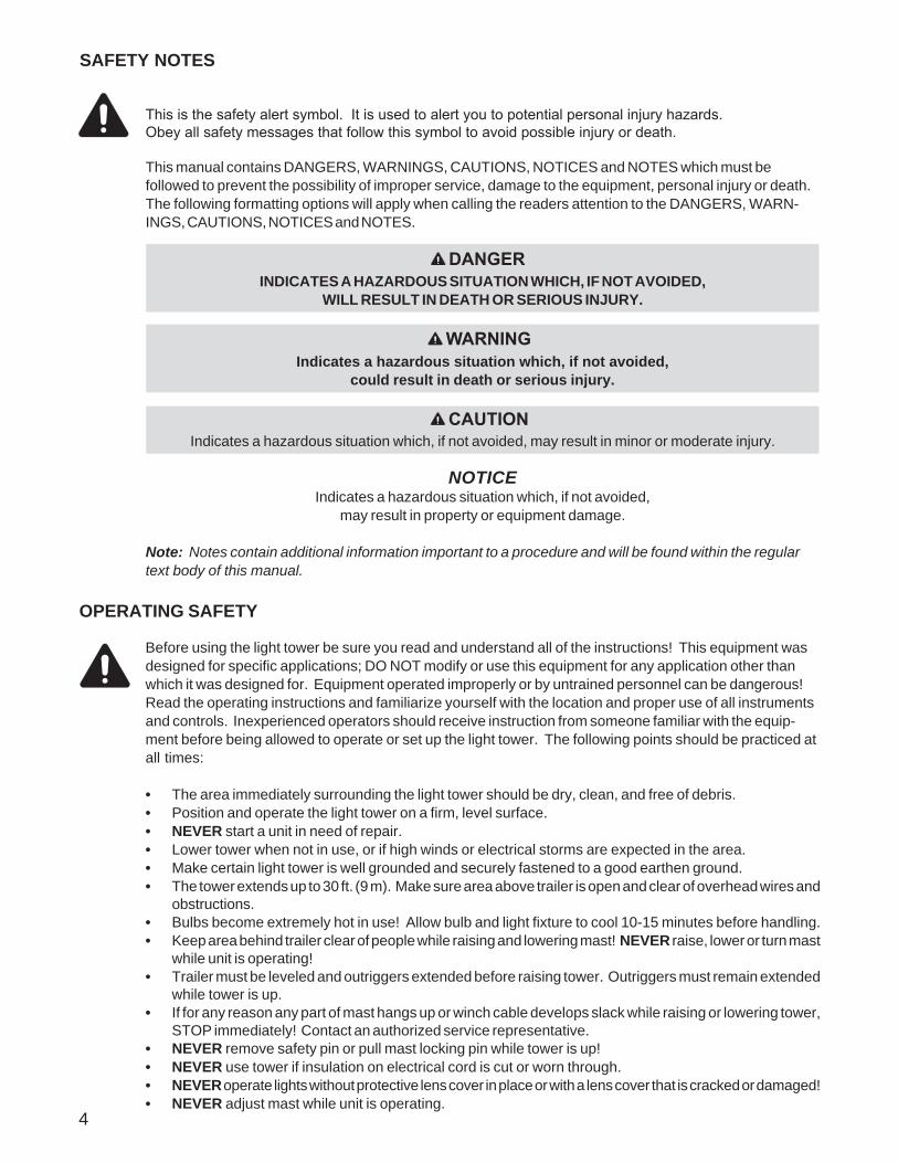
This is the safety alert symbol. It is used to alert you to potential personal injury hazards. Obey all safety messages that follow this symbol to avoid possible injury or death.
This manual contains DANGERS, WARNINGS, CAUTIONS, NOTICES and NOTES which must befollowed to prevent the possibility of improper service, damage to the equipment, personal injury or death.The following formatting options will apply when calling the readers attention to the DANGERS, WARN-INGS, CAUTIONS, NOTICES and NOTES.
SAFETY NOTES
NOTICEIndicates a hazardous situation which, if not avoided,
may result in property or equipment damage.
Note: Notes contain additional information important to a procedure and will be found within the regulartext body of this manual.
DANGERINDICATES A HAZARDOUS SITUATION WHICH, IF NOT AVOIDED,
WILL RESULT IN DEATH OR SERIOUS INJURY.
WARNINGIndicates a hazardous situation which, if not avoided,
could result in death or serious injury.
CAUTIONIndicates a hazardous situation which, if not avoided, may result in minor or moderate injury.
OPERATING SAFETY
Before using the light tower be sure you read and understand all of the instructions! This equipment wasdesigned for specific applications; DO NOT modify or use this equipment for any application other thanwhich it was designed for. Equipment operated improperly or by untrained personnel can be dangerous!Read the operating instructions and familiarize yourself with the location and proper use of all instrumentsand controls. Inexperienced operators should receive instruction from someone familiar with the equip-ment before being allowed to operate or set up the light tower. The following points should be practiced atall times:
• The area immediately surrounding the light tower should be dry, clean, and free of debris.• Position and operate the light tower on a firm, level surface.• NEVER start a unit in need of repair.• Lower tower when not in use, or if high winds or electrical storms are expected in the area.• Make certain light tower is well grounded and securely fastened to a good earthen ground.• The tower extends up to 30 ft. (9 m). Make sure area above trailer is open and clear of overhead wires and
obstructions.• Bulbs become extremely hot in use! Allow bulb and light fixture to cool 10-15 minutes before handling.• Keep area behind trailer clear of people while raising and lowering mast! NEVER raise, lower or turn mast
while unit is operating!• Trailer must be leveled and outriggers extended before raising tower. Outriggers must remain extended
while tower is up.• If for any reason any part of mast hangs up or winch cable develops slack while raising or lowering tower,
STOP immediately! Contact an authorized service representative.• NEVER remove safety pin or pull mast locking pin while tower is up!• NEVER use tower if insulation on electrical cord is cut or worn through.• NEVER operate lights without protective lens cover in place or with a lens cover that is cracked or damaged!• NEVER adjust mast while unit is operating.
5
Internal combustion engines present special hazards during operation and fueling! Failure to follow thesafety guidelines described below could result in severe injury or death. Also read and follow all safetywarnings described in the engine operator’s manual. A copy of this manual was supplied with unit when itwas shipped from the factory.
• DO NOT run engine indoors or in an area with poor ventilation unless exhaust hoses are used. Dieselengine exhaust contains carbon monoxide, a deadly, odorless and colorless gas which, if inhaled,can cause nausea, fainting or death. Make sure engine exhaust cannot seep into closed rooms orventilation equipment.
• DO NOT fill fuel tank near an open flame, while smoking, or while engine is running. DO NOT fill tankin an enclosed area with poor ventilation.
• DO NOT operate with the fuel tank cap loose or missing.• DO NOT touch or lean against hot exhaust pipes or engine cylinders.• DO NOT clean air filter with gasoline or other types of low flash point solvents.• DO NOT remove engine coolant cap while engine is hot.• Keep area around exhaust pipes and air ducts free of debris to reduce the chance of an accidental
fire.• Prolonged exposure to sound levels in excess of 85 DBA can cause permanent hearing loss. Wear
hearing protection when working around a running engine. DO NOT operate the unit without afunctional exhaust system.
• Batteries contain sulfuric acid which can cause severe injury or death. Sulfuric acid can cause eyedamage, burn flesh or eat holes in clothing. Protective eye wear and clothing are necessary whenworking on or around the battery. Always disconnect the NEGATIVE (-) battery cable from thecorresponding terminal before performing any service on the engine or other components.
• Shut the engine down if any of the following conditions exist during operation:1. Noticeable change in engine speed.2. Loss of electrical output.3. Equipment connected to the generator overheats.4. Sparking occurs.5. Engine misfires or there is excessive engine/generator vibration.6. Operating on a combustible surface.7. Protective covers are loose or missing.8. If the ambient air temperature is above 110° F.
ENGINE SAFETY
This unit uses high voltage circuits capable of causing serious injury or death. Only a qualified electricianshould troubleshoot or repair electrical problems occurring in this equipment.
• Before servicing light tower, make sure the engine start switch is turned to OFF, circuit breakers areopen (off) and the negative terminal on the battery is disconnected. NEVER perform even routineservice (oil/filter changes, cleaning, etc.) unless all electrical components are shut down.
• NEVER allow water to accumulate around the base of the light tower. If water is present, DO NOTservice!
• NEVER service electrical components if clothing or skin is wet. If the unit is stored outside, checkthe engine and generator for any moisture and dry the unit before use.
• NEVER wash the unit with a power washer or high pressure hose.• Open main circuit breaker before disconnecting battery cables.• Keep hands, feet, and loose clothing away from moving parts on generator and engine.• Replace all guards and safety devices immediately after servicing.• Make sure slings, chains, hooks, ramps, jacks, and other types of lifting devices are attached
securely and have enough weight-bearing capacity to lift or hold the equipment safely. Alwaysremain aware of the position of other people around you when lifting the equipment.
SERVICE SAFETY
MANUFACTURED BY/FABRIQUE PAR:
GVWR/PNBV:
DATE OF MFG:COLD INFL. PRESS./PRESS.
DE GONF A FROIDGAWR/PNBE TIRE/PNEU RIM/JANTE KPA(PSI/LPC) SGL/DUAL
THIS VIEHICLE CONFORS TO ALL APPLICABLE STANDARDS PRESCRIBED UNDER THE CANADIAN MOTOR VIEHICLE SAFETY REGULATIONSIN ECCEFT ON THE DATE OF MANUFACTURE. / CE VEHICULE EST CONFORME A TOUTES LES NORMES QUI LUI SONT APPLICABLES ENVERTU DU REGLEMENT SUR LA VEHICULES DES AUTOMOBILES DU CANADA EN VIGUEUR A LA DATE SA FABRICATION.THIS VIEHICLE CONFORMS TO ALL APPLICABLE U.S. FEDERAL MOTOR VEHICLE SAFETY STANDARDS (FMVSS) IN EFFECT ON THE DATE OFMANUFACTURE SHOWN ABOVE.
V.I.N./N.I.V.: TYPE/TYPE DE VEHICULE:
MANUFACTURED BY/FABRIQUE PAR:
GVWR/PNBV:
DATE OF MFG:COLD INFL. PRESS./PRESS.
DE GONF A FROIDGAWR/PNBE TIRE/PNEU RIM/JANTE KPA(PSI/LPC) SGL/DUAL
THIS VIEHICLE CONFORS TO ALL APPLICABLE STANDARDS PRESCRIBED UNDER THE CANADIAN MOTOR VIEHICLE SAFETY REGULATIONSIN ECCEFT ON THE DATE OF MANUFACTURE. / CE VEHICULE EST CONFORME A TOUTES LES NORMES QUI LUI SONT APPLICABLES ENVERTU DU REGLEMENT SUR LA VEHICULES DES AUTOMOBILES DU CANADA EN VIGUEUR A LA DATE SA FABRICATION.THIS VIEHICLE CONFORMS TO ALL APPLICABLE U.S. FEDERAL MOTOR VEHICLE SAFETY STANDARDS (FMVSS) IN EFFECT ON THE DATE OFMANUFACTURE SHOWN ABOVE.V.I.N./N.I.V.: TYPE/TYPE DE VEHICULE:
Serial Number
kg lbs
rpm hz amb. temp.
VA
Model
RATING: CONT. STAND BY3 Phase 1 Phase
KVA
LR 114630-1
FOR ELECTRICAL EQUIPMENT ONLY.POUR MATERIAL
ELECTRIQUE SEULEMENT.
MADE IN USA PRODUCTS LLC215 Power DriveBerlin, WI 549231-800-926-9768
TM
Mfg. Code
VA
KW
®
Serial Number
kg lbs
rpm hz amb. temp.
VA
Model
RATING: CONT. STAND BY3 Phase 1 Phase
KVA
LR 114630-1
FOR ELECTRICAL EQUIPMENT ONLY.POUR MATERIAL
ELECTRIQUE SEULEMENT.
MADE IN USA PRODUCTS LLC215 Power DriveBerlin, WI 549231-800-926-9768
TM
Mfg. Code
VA
KW
®
Unit ID TagV.I.N. TagLocated on inside
of panel.
6
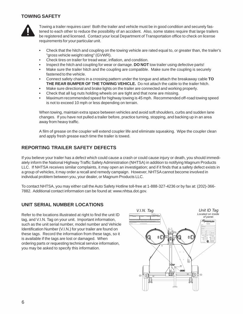
Towing a trailer requires care! Both the trailer and vehicle must be in good condition and securely fas-tened to each other to reduce the possibility of an accident. Also, some states require that large trailersbe registered and licensed. Contact your local Department of Transportation office to check on licenserequirements for your particular unit.
• Check that the hitch and coupling on the towing vehicle are rated equal to, or greater than, the trailer's"gross vehicle weight rating" (GVWR).
• Check tires on trailer for tread wear, inflation, and condition.• Inspect the hitch and coupling for wear or damage. DO NOT tow trailer using defective parts!• Make sure the trailer hitch and the coupling are compatible. Make sure the coupling is securely
fastened to the vehicle.• Connect safety chains in a crossing pattern under the tongue and attach the breakaway cable TO
THE REAR BUMPER OF THE TOWING VEHICLE. Do not attach the cable to the trailer hitch.• Make sure directional and brake lights on the trailer are connected and working properly.• Check that all lug nuts holding wheels on are tight and that none are missing.• Maximum recommended speed for highway towing is 45 mph. Recommended off-road towing speed
is not to exceed 10 mph or less depending on terrain.
When towing, maintain extra space between vehicles and avoid soft shoulders, curbs and sudden lanechanges. If you have not pulled a trailer before, practice turning, stopping, and backing up in an areaaway from heavy traffic.
A film of grease on the coupler will extend coupler life and eliminate squeaking. Wipe the coupler cleanand apply fresh grease each time the trailer is towed.
TOWING SAFETY
REPORTING TRAILER SAFETY DEFECTS
If you believe your trailer has a defect which could cause a crash or could cause injury or death, you should immedi-ately inform the National Highway Traffic Safety Administration (NHTSA) in addition to notifying Magnum ProductsLLC. If NHTSA receives similar complaints, it may open an investigation; and if it finds that a safety defect exists ina group of vehicles, it may order a recall and remedy campaign. However, NHTSA cannot become involved inindividual problem between you, your dealer, or Magnum Products LLC.
To contact NHTSA, you may either call the Auto Safety Hotline toll-free at 1-888-327-4236 or by fax at: (202)-366-7882. Additional contact information can be found at: www.nhtsa.dot.gov.
UNIT SERIAL NUMBER LOCATIONS
Refer to the locations illustrated at right to find the unit IDtag, and V.I.N. Tag on your unit. Important information,such as the unit serial number, model number and VehicleIdentification Number (V.I.N.) for your trailer are found onthese tags. Record the information from these tags, so itis available if the tags are lost or damaged. Whenordering parts or requesting technical service information,you may be asked to specify this information.
7
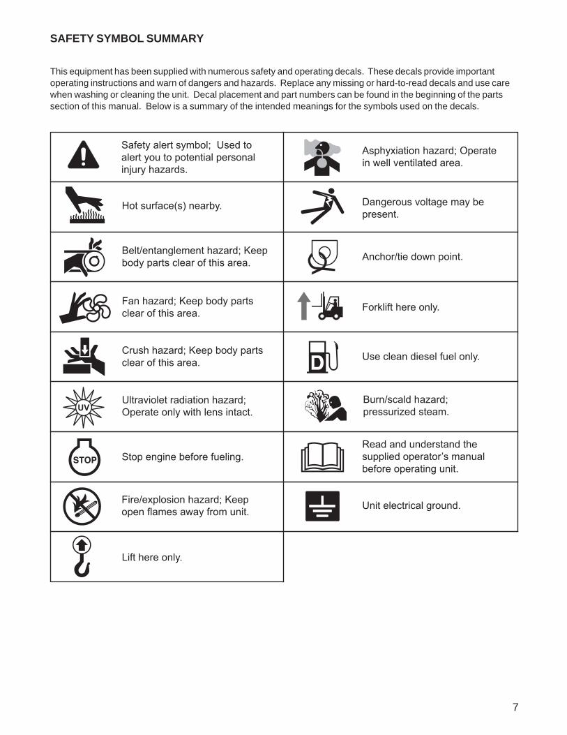
SAFETY SYMBOL SUMMARY
This equipment has been supplied with numerous safety and operating decals. These decals provide importantoperating instructions and warn of dangers and hazards. Replace any missing or hard-to-read decals and use carewhen washing or cleaning the unit. Decal placement and part numbers can be found in the beginning of the partssection of this manual. Below is a summary of the intended meanings for the symbols used on the decals.
UV
Hot surface(s) nearby.
Fire/explosion hazard; Keep open flames away from unit.
Read and understand the supplied operator’s manual before operating unit.
Ultraviolet radiation hazard; Operate only with lens intact.
Use clean diesel fuel only.
Unit electrical ground.
Anchor/tie down point.
Lift here only.
Asphyxiation hazard; Operate in well ventilated area.
Dangerous voltage may bepresent.
Crush hazard; Keep body partsclear of this area.
Burn/scald hazard; pressurized steam.
Fan hazard; Keep body parts clear of this area. Forklift here only.
Belt/entanglement hazard; Keep body parts clear of this area.
Safety alert symbol; Used to alert you to potential personal injury hazards.
Stop engine before fueling.
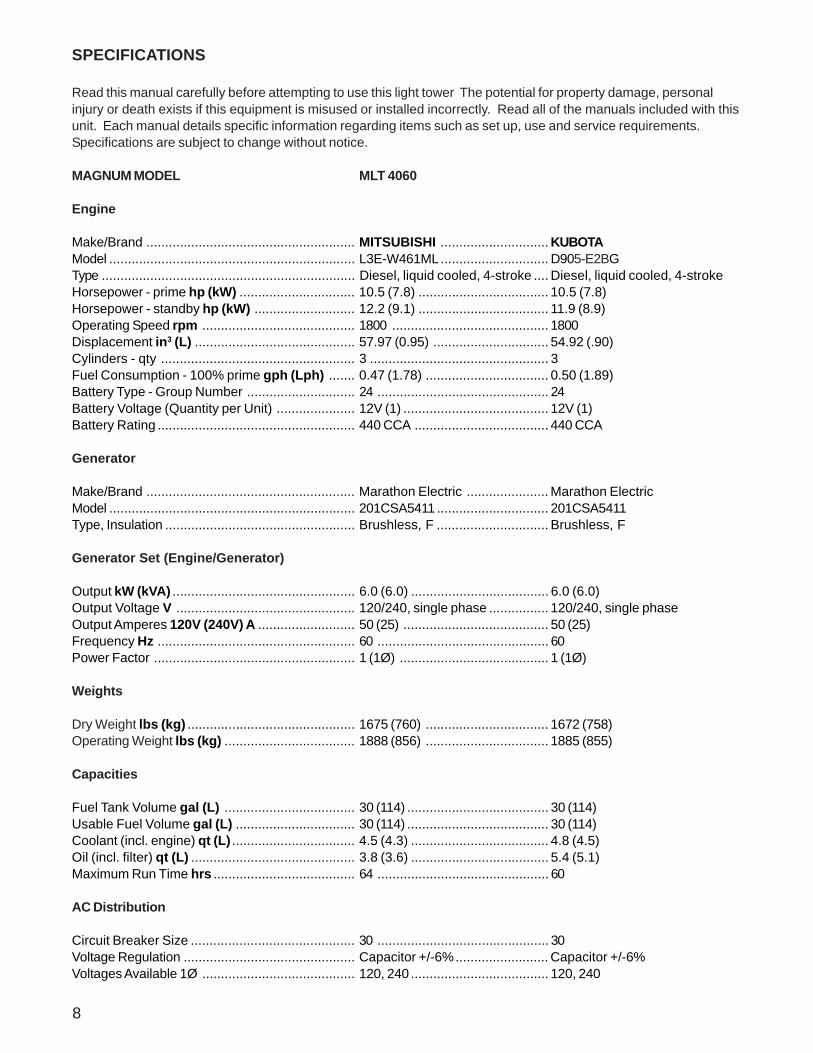
SPECIFICATIONS
Read this manual carefully before attempting to use this light tower The potential for property damage, personalinjury or death exists if this equipment is misused or installed incorrectly. Read all of the manuals included with thisunit. Each manual details specific information regarding items such as set up, use and service requirements.Specifications are subject to change without notice.
MAGNUM MODEL MLT 4060
Engine
Make/Brand ........................................................ MITSUBISHI ............................. KUBOTAModel .................................................................. L3E-W461ML............................. D905-E2BGType .................................................................... Diesel, liquid cooled, 4-stroke .... Diesel, liquid cooled, 4-strokeHorsepower - prime hp (kW) ............................... 10.5 (7.8) ................................... 10.5 (7.8)Horsepower - standby hp (kW) ........................... 12.2 (9.1) ................................... 11.9 (8.9)Operating Speed rpm ......................................... 1800 .......................................... 1800Displacement in3 (L) ........................................... 57.97 (0.95) ............................... 54.92 (.90)Cylinders - qty .................................................... 3 ................................................ 3Fuel Consumption - 100% prime gph (Lph) ....... 0.47 (1.78) ................................. 0.50 (1.89)Battery Type - Group Number ............................. 24 .............................................. 24Battery Voltage (Quantity per Unit) ..................... 12V (1) ....................................... 12V (1)Battery Rating ..................................................... 440 CCA .................................... 440 CCA
Generator
Make/Brand ........................................................ Marathon Electric ...................... Marathon ElectricModel .................................................................. 201CSA5411 .............................. 201CSA5411Type, Insulation ................................................... Brushless, F .............................. Brushless, F
Generator Set (Engine/Generator)
Output kW (kVA) ................................................. 6.0 (6.0) ..................................... 6.0 (6.0)Output Voltage V ................................................ 120/240, single phase ................ 120/240, single phaseOutput Amperes 120V (240V) A .......................... 50 (25) ....................................... 50 (25)Frequency Hz ..................................................... 60 .............................................. 60Power Factor ...................................................... 1 (1Ø) ........................................ 1 (1Ø)
Weights
Dry Weight lbs (kg) ............................................. 1675 (760) ................................. 1672 (758)Operating Weight lbs (kg) ................................... 1888 (856) ................................. 1885 (855)
Capacities
Fuel Tank Volume gal (L) ................................... 30 (114) ...................................... 30 (114)Usable Fuel Volume gal (L) ................................ 30 (114) ...................................... 30 (114)Coolant (incl. engine) qt (L) ................................. 4.5 (4.3) ..................................... 4.8 (4.5)Oil (incl. filter) qt (L) ............................................ 3.8 (3.6) ..................................... 5.4 (5.1)Maximum Run Time hrs ...................................... 64 .............................................. 60
AC Distribution
Circuit Breaker Size ............................................ 30 .............................................. 30Voltage Regulation .............................................. Capacitor +/-6%......................... Capacitor +/-6%Voltages Available 1Ø ......................................... 120, 240 ..................................... 120, 240
8

9
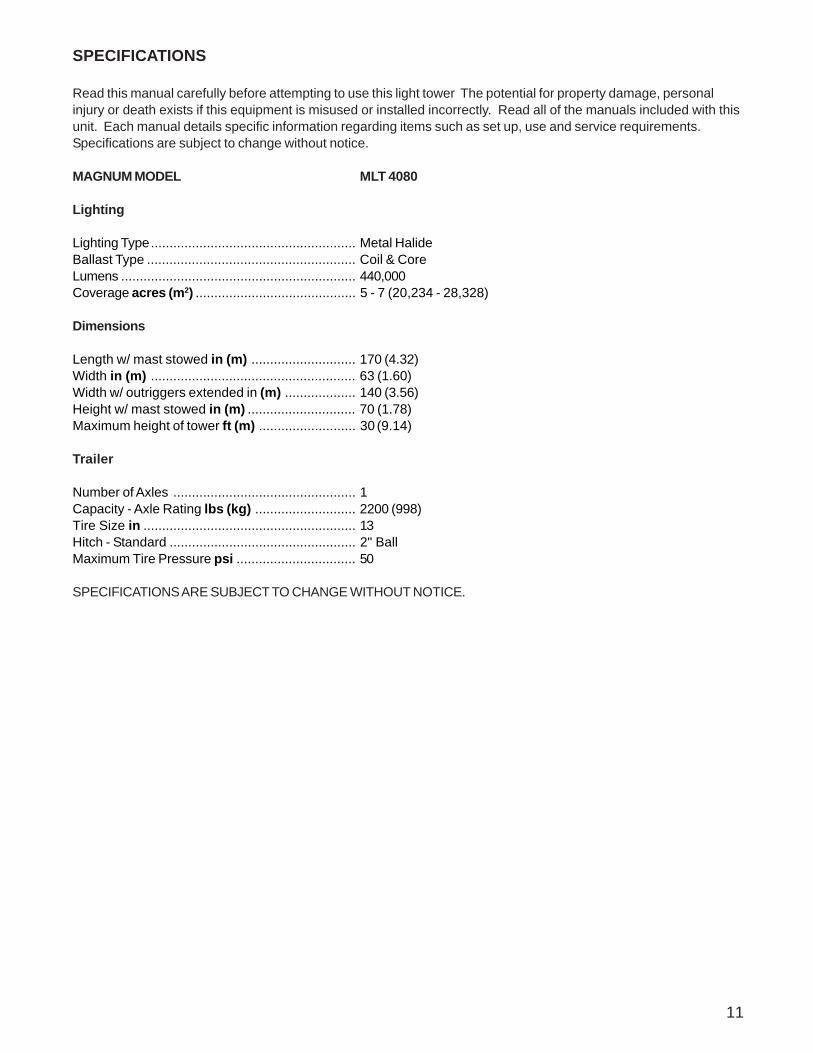
SPECIFICATIONS
Read this manual carefully before attempting to use this light tower The potential for property damage, personalinjury or death exists if this equipment is misused or installed incorrectly. Read all of the manuals included with thisunit. Each manual details specific information regarding items such as set up, use and service requirements.Specifications are subject to change without notice.
MAGNUM MODEL MLT 4060
Lighting
Lighting Type....................................................... Metal HalideBallast Type ........................................................ Coil & CoreLumens ............................................................... 440,000Coverage acres (m2) ........................................... 5 - 7 (20,234 - 28,328)
Dimensions
Length w/ mast stowed in (m) ............................ 170 (4.32)Width in (m) ....................................................... 63 (1.60)Width w/ outriggers extended in (m) ................... 140 (3.56)Height w/ mast stowed in (m) ............................. 70 (1.78)Maximum height of tower ft (m) .......................... 30 (9.14)
Trailer
Number of Axles ................................................. 1Capacity - Axle Rating lbs (kg) ........................... 2200 (998)Tire Size in ......................................................... 13Hitch - Standard .................................................. 2" BallMaximum Tire Pressure psi ................................ 50
SPECIFICATIONS ARE SUBJECT TO CHANGE WITHOUT NOTICE.

10
SPECIFICATIONS
Read this manual carefully before attempting to use this light tower The potential for property damage, personalinjury or death exists if this equipment is misused or installed incorrectly. Read all of the manuals included with thisunit. Each manual details specific information regarding items such as set up, use and service requirements.Specifications are subject to change without notice.
MAGNUM MODEL MLT 4080
Engine
Make/Brand ........................................................ MITSUBISHIModel .................................................................. L3E-W461MLType .................................................................... Diesel, liquid cooled, 4-strokeHorsepower - prime hp (kW) ............................... 10.5 (7.8)Horsepower - standby hp (kW) ........................... 12.2 (9.1)Operating Speed rpm ......................................... 1800Displacement in3 (L) ........................................... 57.97 (0.95)Cylinders - qty .................................................... 3Fuel Consumption - 100% prime gph (Lph) ....... 0.63 (2.38)Battery Type - Group Number ............................. 24Battery Voltage (Quantity per Unit) ..................... 12V (1)Battery Rating ..................................................... 440 CCA
Generator
Make/Brand ........................................................ Marathon ElectricModel .................................................................. 332CSA5211Type, Insulation ................................................... Brushless, F
Generator Set (Engine/Generator)
Output kW (kVA) ................................................. 7.3 (7.3)Output Voltage V ................................................ 120/240, single phaseOutput Amperes 120V (240V) A .......................... 61 (30)Frequency Hz ..................................................... 60Power Factor ...................................................... 1 (1Ø)
Weights
Dry Weight lbs (kg) ............................................. 1695 (769)Operating Weight lbs (kg) ................................... 1908 (865)
Capacities
Fuel Tank Volume gal (L) ................................... 30 (114)Usable Fuel Volume gal (L) ................................ 30 (114)Coolant (incl. engine) qt (L) ................................. 4.5 (4.3)Oil (incl. filter) qt (L) ............................................ 3.8 (3.6)Maximum Run Time hrs ...................................... 48
AC Distribution
Circuit Breaker Size ............................................ 40Voltage Regulation .............................................. Capacitor +/-6%Voltages Available 1Ø ......................................... 120, 240
11
SPECIFICATIONS
Read this manual carefully before attempting to use this light tower The potential for property damage, personalinjury or death exists if this equipment is misused or installed incorrectly. Read all of the manuals included with thisunit. Each manual details specific information regarding items such as set up, use and service requirements.Specifications are subject to change without notice.
MAGNUM MODEL MLT 4080
Lighting
Lighting Type....................................................... Metal HalideBallast Type ........................................................ Coil & CoreLumens ............................................................... 440,000Coverage acres (m2) ........................................... 5 - 7 (20,234 - 28,328)
Dimensions
Length w/ mast stowed in (m) ............................ 170 (4.32)Width in (m) ....................................................... 63 (1.60)Width w/ outriggers extended in (m) ................... 140 (3.56)Height w/ mast stowed in (m) ............................. 70 (1.78)Maximum height of tower ft (m) .......................... 30 (9.14)
Trailer
Number of Axles ................................................. 1Capacity - Axle Rating lbs (kg) ........................... 2200 (998)Tire Size in ......................................................... 13Hitch - Standard .................................................. 2" BallMaximum Tire Pressure psi ................................ 50
SPECIFICATIONS ARE SUBJECT TO CHANGE WITHOUT NOTICE.
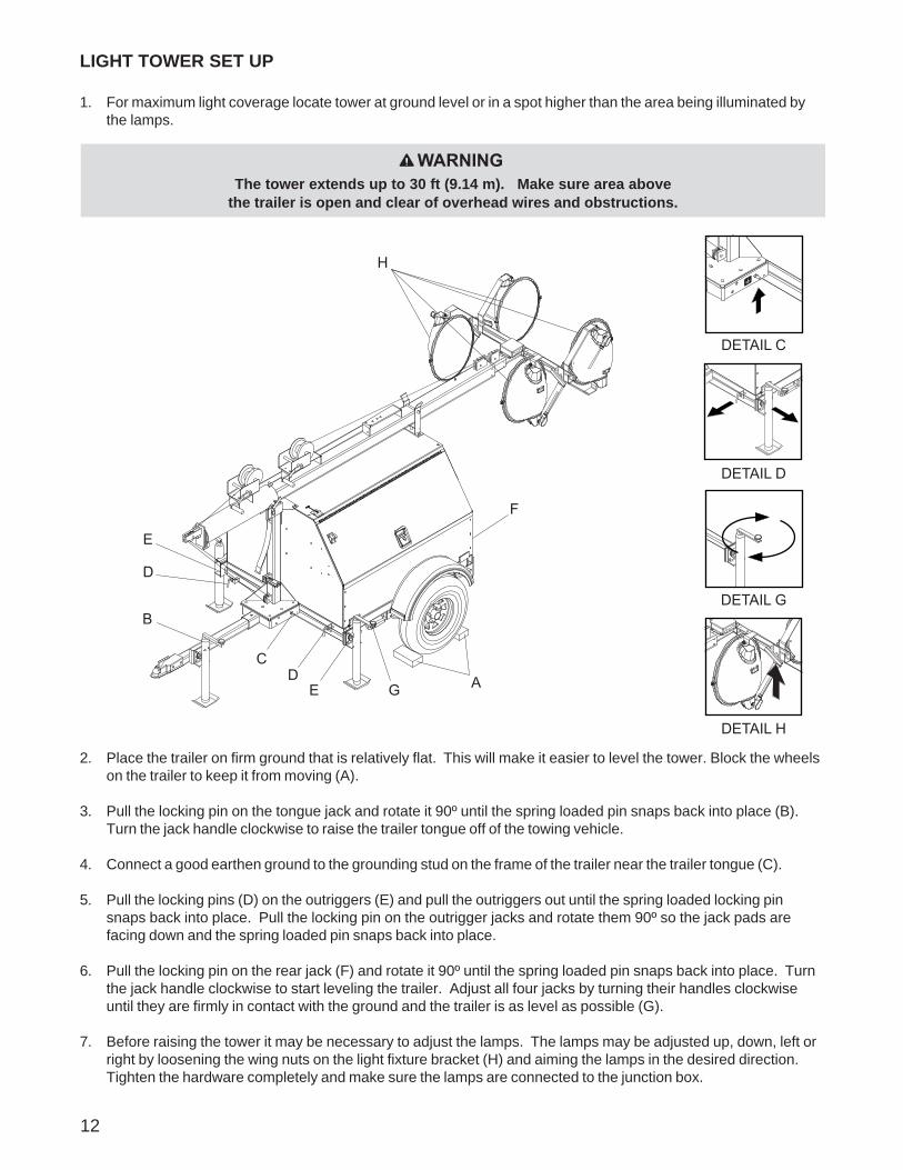
LIGHT TOWER SET UP
1. For maximum light coverage locate tower at ground level or in a spot higher than the area being illuminated bythe lamps.
2. Place the trailer on firm ground that is relatively flat. This will make it easier to level the tower. Block the wheelson the trailer to keep it from moving (A).
3. Pull the locking pin on the tongue jack and rotate it 90º until the spring loaded pin snaps back into place (B).Turn the jack handle clockwise to raise the trailer tongue off of the towing vehicle.
4. Connect a good earthen ground to the grounding stud on the frame of the trailer near the trailer tongue (C).
5. Pull the locking pins (D) on the outriggers (E) and pull the outriggers out until the spring loaded locking pinsnaps back into place. Pull the locking pin on the outrigger jacks and rotate them 90º so the jack pads arefacing down and the spring loaded pin snaps back into place.
6. Pull the locking pin on the rear jack (F) and rotate it 90º until the spring loaded pin snaps back into place. Turnthe jack handle clockwise to start leveling the trailer. Adjust all four jacks by turning their handles clockwiseuntil they are firmly in contact with the ground and the trailer is as level as possible (G).
7. Before raising the tower it may be necessary to adjust the lamps. The lamps may be adjusted up, down, left orright by loosening the wing nuts on the light fixture bracket (H) and aiming the lamps in the desired direction.Tighten the hardware completely and make sure the lamps are connected to the junction box.
12
The tower extends up to 30 ft (9.14 m). Make sure area abovethe trailer is open and clear of overhead wires and obstructions.
WARNING
DETAIL C
DETAIL D
DETAIL G
DETAIL H
H
F
AGED
C
B
D
E
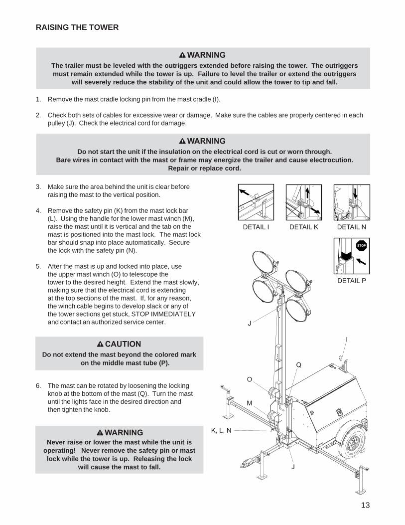
1. Remove the mast cradle locking pin from the mast cradle (I).
2. Check both sets of cables for excessive wear or damage. Make sure the cables are properly centered in eachpulley (J). Check the electrical cord for damage.
3. Make sure the area behind the unit is clear beforeraising the mast to the vertical position.
4. Remove the safety pin (K) from the mast lock bar(L). Using the handle for the lower mast winch (M),raise the mast until it is vertical and the tab on themast is positioned into the mast lock. The mast lockbar should snap into place automatically. Securethe lock with the safety pin (N).
5. After the mast is up and locked into place, usethe upper mast winch (O) to telescope thetower to the desired height. Extend the mast slowly,making sure that the electrical cord is extendingat the top sections of the mast. If, for any reason,the winch cable begins to develop slack or any ofthe tower sections get stuck, STOP IMMEDIATELYand contact an authorized service center.
6. The mast can be rotated by loosening the lockingknob at the bottom of the mast (Q). Turn the mastuntil the lights face in the desired direction andthen tighten the knob.
I
J
J
K, L, N
M
O
Q
13
The trailer must be leveled with the outriggers extended before raising the tower. The outriggersmust remain extended while the tower is up. Failure to level the trailer or extend the outriggers
will severely reduce the stability of the unit and could allow the tower to tip and fall.
WARNING
Do not start the unit if the insulation on the electrical cord is cut or worn through.Bare wires in contact with the mast or frame may energize the trailer and cause electrocution.
Repair or replace cord.
WARNING
RAISING THE TOWER
CAUTIONDo not extend the mast beyond the colored mark
on the middle mast tube (P).
Never raise or lower the mast while the unit isoperating! Never remove the safety pin or mastlock while the tower is up. Releasing the lock
will cause the mast to fall.
WARNING
DETAIL I DETAIL K
STOP
DETAIL N
DETAIL P
V
U
S
R,T W
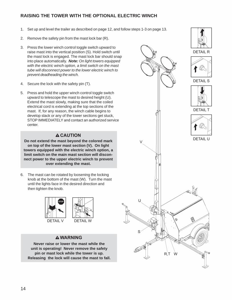
1. Set up and level the trailer as described on page 12, and follow steps 1-3 on page 13.
2. Remove the safety pin from the mast lock bar (R).
3. Press the lower winch control toggle switch upward toraise mast into the vertical position (S). Hold switch untilthe mast lock is engaged. The mast lock bar should snapinto place automatically. Note: On light towers equippedwith the electric winch option, a limit switch on the masttube will disconnect power to the lower electric winch toprevent deadheading the winch.
4. Secure the lock with the safety pin (T).
5. Press and hold the upper winch control toggle switchupward to telescope the mast to desired height (U).Extend the mast slowly, making sure that the coiledelectrical cord is extending at the top sections of themast. If, for any reason, the winch cable begins todevelop slack or any of the tower sections get stuck,STOP IMMEDIATELY and contact an authorized servicecenter.
6. The mast can be rotated by loosening the lockingknob at the bottom of the mast (W). Turn the mastuntil the lights face in the desired direction andthen tighten the knob.
14
WARNINGNever raise or lower the mast while the
unit is operating! Never remove the safetypin or mast lock while the tower is up.
Releasing the lock will cause the mast to fall.
RAISING THE TOWER WITH THE OPTIONAL ELECTRIC WINCH
CAUTIONDo not extend the mast beyond the colored mark
on top of the lower mast section (V). On lighttowers equipped with the electric winch option, alimit switch on the main mast section will discon-nect power to the upper electric winch to prevent
over extending the mast.
DETAIL R
DETAIL S
DETAIL T
DETAIL U
STOP
DETAIL V DETAIL W
15
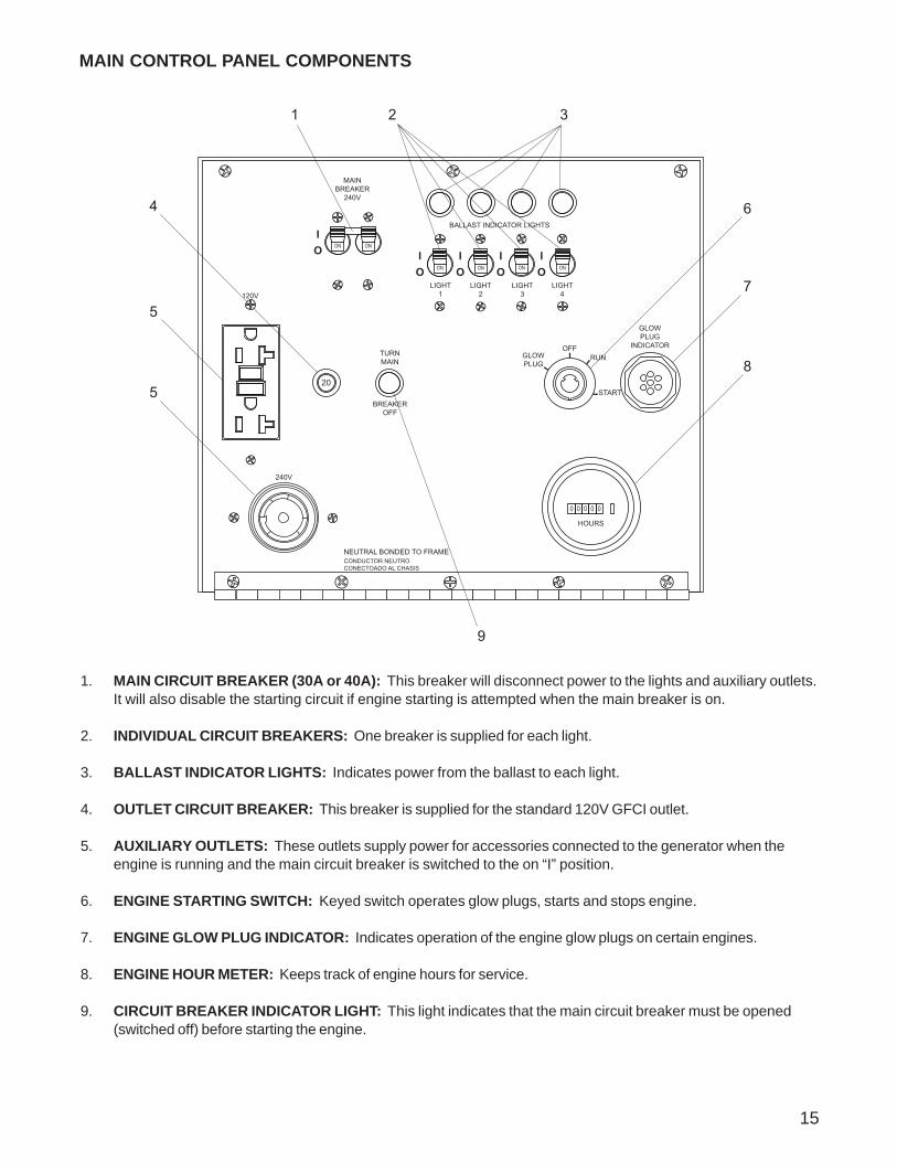
1. MAIN CIRCUIT BREAKER (30A or 40A): This breaker will disconnect power to the lights and auxiliary outlets.It will also disable the starting circuit if engine starting is attempted when the main breaker is on.
2. INDIVIDUAL CIRCUIT BREAKERS: One breaker is supplied for each light.
3. BALLAST INDICATOR LIGHTS: Indicates power from the ballast to each light.
4. OUTLET CIRCUIT BREAKER: This breaker is supplied for the standard 120V GFCI outlet.
5. AUXILIARY OUTLETS: These outlets supply power for accessories connected to the generator when theengine is running and the main circuit breaker is switched to the on “I” position.
6. ENGINE STARTING SWITCH: Keyed switch operates glow plugs, starts and stops engine.
7. ENGINE GLOW PLUG INDICATOR: Indicates operation of the engine glow plugs on certain engines.
8. ENGINE HOUR METER: Keeps track of engine hours for service.
9. CIRCUIT BREAKER INDICATOR LIGHT: This light indicates that the main circuit breaker must be opened(switched off) before starting the engine.
MAIN CONTROL PANEL COMPONENTS
ON ON
MAINBREAKER
240V
IO
0 0 00 0
HOURS
20
ONONON ON
LIGHT1
LIGHT2
LIGHT3
LIGHT4
BALLAST INDICATOR LIGHTS
IO
IO
IO
IO
GLOWPLUG
INDICATORGLOWPLUG
OFFRUN
START
120V
240V
NEUTRAL BONDED TO FRAMECONDUCTOR NEUTROCONECTOADO AL CHASIS
TURNMAIN
BREAKEROFF
1 2 3
6
7
8
9
5
5
4
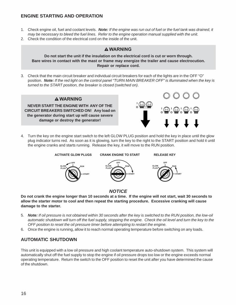
1. Check engine oil, fuel and coolant levels. Note: If the engine was run out of fuel or the fuel tank was drained, itmay be necessary to bleed the fuel lines. Refer to the engine operation manual supplied with the unit.
2. Check the condition of the electrical cord on the inside of the unit.
3. Check that the main circuit breaker and individual circuit breakers for each of the lights are in the OFF “O”position. Note: If the red light on the control panel “TURN MAIN BREAKER OFF” is illuminated when the key isturned to the START position, the breaker is closed (switched on).
4. Turn the key on the engine start switch to the left GLOW PLUG position and hold the key in place until the glowplug indicator turns red. As soon as it is glowing, turn the key to the right to the START position and hold it untilthe engine cranks and starts running. Release the key, it will move to the RUN position.
NOTICEDo not crank the engine longer than 10 seconds at a time. If the engine will not start, wait 30 seconds toallow the starter motor to cool and then repeat the starting procedure. Excessive cranking will causedamage to the starter.
5. Note: If oil pressure is not obtained within 30 seconds after the key is switched to the RUN position, the low-oilautomatic shutdown will turn off the fuel supply, stopping the engine. Check the oil level and turn the key to theOFF position to reset the oil pressure timer before attempting to restart the engine.
6. Once the engine is running, allow it to reach normal operating temperature before switching on any loads.
AUTOMATIC SHUTDOWN
This unit is equipped with a low oil pressure and high coolant temperature auto-shutdown system. This system willautomatically shut off the fuel supply to stop the engine if oil pressure drops too low or the engine exceeds normaloperating temperature. Return the switch to the OFF position to reset the unit after you have determined the causeof the shutdown.
16
ENGINE STARTING AND OPERATION
GLOWPLUG
OFF
RUN
START
GLOWPLUG
OFF
RUN
START
GLOWPLUG
OFF
RUN
START
RELEASE KEYACTIVATE GLOW PLUGS CRANK ENGINE TO START
Do not start the unit if the insulation on the electrical cord is cut or worn through.Bare wires in contact with the mast or frame may energize the trailer and cause electrocution.
Repair or replace cord.
WARNING
NEVER START THE ENGINE WITH ANY OF THECIRCUIT BREAKERS SWITCHED ON! Any load on
the generator during start up will cause severedamage or destroy the generator!
WARNING

20
120V
240V
120V GFCI OUTLET
240V TWIST-LOCKOUTLET
1. Once the engine is up to temperature and running smoothly,switch main circuit breaker (1) to the ON “I” position.
2. With main circuit breaker on, switch each individual circuitbreaker for the lights (2) to ON “I”, one at a time.
3. The ballast indicator lights (3) will come on momentarily as thelights strike. As the lights warm up, the ballast indicator lightswill continue to get brighter and then remain on. This confirmsthat power is coming from the ballasts to the lights.
4. If an indicator light does not come on, the ballast may need to beserviced. If the indicator light comes on and stays lit but therelated light is not illuminated, check the bulb or the mast wiring.
5. The lights require a warm up period of 5-15 minutes before theyreach full output. If the lights are shutdown, they require a cool-down period of approximately 10 minutes before they can beswitched on again.
6. The light tower uses four 1000W bulbs. When checking or replacing the bulbs, wipe them with a clean cloth toavoid leaving any grease, oil residue or fingerprints on the glass. Any residue can create a hot spot on the bulb,causing premature bulb failure.
AUXILIARY OUTLETS
The control panel is equipped with two outlets for runningaccessories or tools from the generator. Power is supplied tothe outlets any time the engine is running and the main circuitbreaker is switched ON “I”. Note: Do not pull more than 1000Wfrom each outlet when the lights are on. This will overload thegenerator and cause the main circuit breaker to trip. Should thebreaker trip, switch off the lights, remove some of the load tothe outlets and wait 10 minutes for the bulbs to cool beforeturning them back on.
With all of the lights off, the full generator output may be usedwith the optional 240V twist-lock outlet.
17
Bulbs become extremely hot in use! Allow bulb fixture to cool 10-15 minutes before handling.
WARNING
NEVER OPERATE THE LIGHTS WITHOUT THE PROTECTIVE LENS COVER OR WITH A LENSCOVER THAT IS CRACKED OR DAMAGED! The bulbs in the light fixtures produce high
temperatures and operate under pressure. A broken or missing lens cover could cause thebulbs to shatter, causing injury.
WARNING
LIGHT OPERATION
ON ON
MAINBREAKER
240V
IO
0 0 00 0
HOURS
20
ONONON ON
LIGHT1
LIGHT2
LIGHT3
LIGHT4
BALLAST INDICATOR LIGHTS
IO
IO
IO
IO
GLOWPLUG
INDICATORGLOWPLUG
OFFRUN
START
120V
240V
NEUTRAL BONDED TO FRAMECONDUCTOR NEUTROCONECTOADO AL CHASIS
TURNMAIN
BREAKEROFF
1 2 3
18
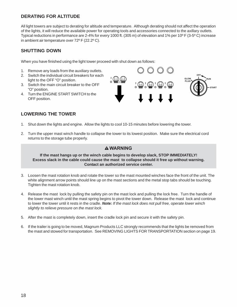
DERATING FOR ALTITUDE
All light towers are subject to derating for altitude and temperature. Although derating should not affect the operationof the lights, it will reduce the available power for operating tools and accessories connected to the axillary outlets.Typical reductions in performance are 2-4% for every 1000 ft. (305 m) of elevation and 1% per 10º F (3-5º C) increasein ambient air temperature over 72º F (22.2º C).
SHUTTING DOWN
When you have finished using the light tower proceed with shut down as follows:
1. Remove any loads from the auxiliary outlets.2. Switch the individual circuit breakers for each
light to the OFF “O” position.3. Switch the main circuit breaker to the OFF
“O” position.4. Turn the ENGINE START SWITCH to the
OFF position.
LOWERING THE TOWER
1. Shut down the lights and engine. Allow the lights to cool 10-15 minutes before lowering the tower.
2. Turn the upper mast winch handle to collapse the tower to its lowest position. Make sure the electrical cordreturns to the storage tube properly.
3. Loosen the mast rotation knob and rotate the tower so the mast mounted winches face the front of the unit. Thewhite alignment arrow points should line up on the mast sections and the metal stop tabs should be touching.Tighten the mast rotation knob.
4. Release the mast lock by pulling the safety pin on the mast lock and pulling the lock free. Turn the handle ofthe lower mast winch until the mast spring begins to pivot the tower down. Release the mast lock and continueto lower the tower until it rests in the cradle. Note: If the mast lock does not pull free, operate lower winchslightly to relieve pressure on the mast lock.
5. After the mast is completely down, insert the cradle lock pin and secure it with the safety pin.
6. If the trailer is going to be moved, Magnum Products LLC strongly recommends that the lights be removed fromthe mast and stowed for transportation. See REMOVING LIGHTS FOR TRANSPORTATION section on page 19.
WARNINGIf the mast hangs up or the winch cable begins to develop slack, STOP IMMEDIATELY!
Excess slack in the cable could cause the mast to collapse should it free up without warning.Contact an authorized service center.

19
LOWERING THE TOWER EQUIPPED WITH THE OPTIONAL ELECTRIC WINCH
1. Shut down the lights and engine. Allow the lights to cool 10-15 minutes before lowering the tower.2. Loosen the mast rotation knob and rotate the tower so the mast mounted winches face the front of the unit. The
white alignment arrow points should line up on the mast sections and the metal stop tabs should be touching.Tighten the mast rotation knob.
3. Press and hold the upper winch control toggle switch downward to collapse the mast to its lowest level. Makesure the coiled electrical cord on the top sections of the mast does not get tangled on the mast sections. Note:Some electric winch models are equipped with an anti-backlash safety limit switch. This switch will disconnectpower to the winch if excess cable slack is detected, preventing accidental lowering of the tower. If, for anyreason, the cable begins to develop slack or any of the tower sections get stuck, STOP IMMEDIATELY andcontact an authorized service center.
4. Release the mast lock bar by pulling the safety pin on the mast lock and pulling the lock bar free. Lower themast by holding the lower winch control toggle switch to the right until the mast is resting in the transport cradle.Note: If the lock bar does not pull free, activate lower winch slightly to relieve pressure on the mast lock bar.
5. After the mast is completely down, insert the cradle lock pin and secure it with the safety pin.6. If the trailer is going to be moved, Magnum Products LLC strongly recommends that the lights be removed from
the mast and stowed for transportation.
REMOVING THE LIGHTS FOR TRANSPORTATION
1. On units equipped with quick disconnect fittings for the lights, disconnect the powercords from the junction box at the top of the mast. Replace the dust caps on thejunction box. On hard wired units, remove the junction box cover, located on the top ofthe mast, and disconnect ONLY the mast light wires from the terminal blocks. Torelease the mast light wires from the terminal blocks, flip the locking levers down andpull out the appropriate wires (A).
2. Remove the lights by removing the wing nut that holds the light fixture bracket to thecross tube. Attach the lights to the storage brackets (if equipped) located on the masttube on either side of the central lifting eye.
TOWING THE TRAILER
Once the engine is shut down and the mast and lights are properly stowed, the trailer can be made ready for transport.
1. Raise the rear jack completely and release the locking pin to rotate it up into the travel position. Make sure thelocking pin snaps into place.
2. Raise the outrigger jacks completely and release the jack locking pin to swing the jacks up into the travelposition. Make sure the locking pins snap into place. Release the outrigger locking pins and slide theoutriggers into the trailer frame until the locking pins snap into place.
3. Use the drawbar jack to raise or lower the trailer onto the hitch of the towing vehicle. Lock the hitch couplingand attach the safety chains or cables to the vehicle. Release the jack locking pin and rotate the jack into thetravel position. Make sure the locking pin snaps into place.
4. To ensure proper operation of the jacks, lube the grease fittings located on the leveling jacks.5. Connect any trailer wiring to the tow vehicle. Check for proper operation of the stop and signal lights.6. Make sure the cradle locking pin is in place.7. Make sure the doors are properly latched.8. If the trailer is going to be driven over rough ground, remove the bulbs from the light fixtures.9. Check for proper inflation of the trailer tires. The maximum tire inflation is 50 psi.10. Attach a red flag to the end of the mast before towing.11. Maximum recommended speed for highway towing is 45 mph. Recommended off-road towing speed is not to
exceed 10 mph or less depending on terrain.
A
20
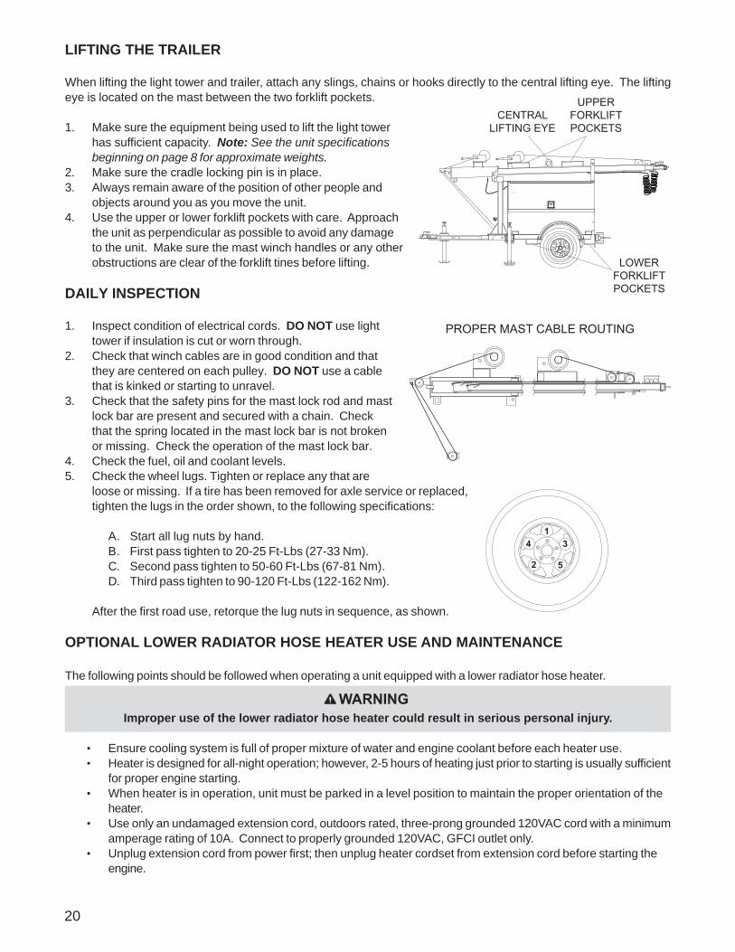
LIFTING THE TRAILER
When lifting the light tower and trailer, attach any slings, chains or hooks directly to the central lifting eye. The liftingeye is located on the mast between the two forklift pockets.
1. Make sure the equipment being used to lift the light towerhas sufficient capacity. Note: See the unit specificationsbeginning on page 8 for approximate weights.
2. Make sure the cradle locking pin is in place.3. Always remain aware of the position of other people and
objects around you as you move the unit.4. Use the upper or lower forklift pockets with care. Approach
the unit as perpendicular as possible to avoid any damageto the unit. Make sure the mast winch handles or any otherobstructions are clear of the forklift tines before lifting.
DAILY INSPECTION
1. Inspect condition of electrical cords. DO NOT use lighttower if insulation is cut or worn through.
2. Check that winch cables are in good condition and thatthey are centered on each pulley. DO NOT use a cablethat is kinked or starting to unravel.
3. Check that the safety pins for the mast lock rod and mastlock bar are present and secured with a chain. Checkthat the spring located in the mast lock bar is not brokenor missing. Check the operation of the mast lock bar.
4. Check the fuel, oil and coolant levels.5. Check the wheel lugs. Tighten or replace any that are
loose or missing. If a tire has been removed for axle service or replaced,tighten the lugs in the order shown, to the following specifications:
A. Start all lug nuts by hand.B. First pass tighten to 20-25 Ft-Lbs (27-33 Nm).C. Second pass tighten to 50-60 Ft-Lbs (67-81 Nm).D. Third pass tighten to 90-120 Ft-Lbs (122-162 Nm).
After the first road use, retorque the lug nuts in sequence, as shown.
OPTIONAL LOWER RADIATOR HOSE HEATER USE AND MAINTENANCE
The following points should be followed when operating a unit equipped with a lower radiator hose heater.
• Ensure cooling system is full of proper mixture of water and engine coolant before each heater use.• Heater is designed for all-night operation; however, 2-5 hours of heating just prior to starting is usually sufficient
for proper engine starting.• When heater is in operation, unit must be parked in a level position to maintain the proper orientation of the
heater.• Use only an undamaged extension cord, outdoors rated, three-prong grounded 120VAC cord with a minimum
amperage rating of 10A. Connect to properly grounded 120VAC, GFCI outlet only.• Unplug extension cord from power first; then unplug heater cordset from extension cord before starting the
engine.
CENTRALLIFTING EYE
UPPERFORKLIFTPOCKETS
LOWERFORKLIFTPOCKETS
5 2
3 4 1
Improper use of the lower radiator hose heater could result in serious personal injury.
WARNING
PROPER MAST CABLE ROUTING
21
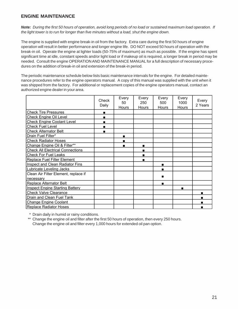
* Drain daily in humid or rainy conditions.** Change the engine oil and filter after the first 50 hours of operation, then every 250 hours.
Change the engine oil and filter every 1,000 hours for extended oil pan option.
Check Daily
Every50
Hours
Every250
Hours
Every500
Hours
Every1000Hours
Every2 Years
Check Tire Pressures ■Check Engine Oil Level ■Check Engine Coolant Level ■Check Fuel Level ■Check Alternator Belt ■Drain Fuel Filter* ■Check Radiator Hoses ■Change Engine Oil & Filter** ■ ■Check All Electrical Connections ■Check For Fuel Leaks ■Replace Fuel Filter Element ■Inspect and Clean Radiator Fins ■ Lubricate Leveling Jacks ■ Clean Air Filter Element, replace if necessary ■
Replace Alternator Belt ■ Inspect Engine Starting Battery ■ Check Valve Clearance ■ Drain and Clean Fuel Tank ■ Change Engine Coolant ■ Replace Radiator Hoses ■
ENGINE MAINTENANCE
Note: During the first 50 hours of operation, avoid long periods of no load or sustained maximum load operation. Ifthe light tower is to run for longer than five minutes without a load, shut the engine down.
The engine is supplied with engine break-in oil from the factory. Extra care during the first 50 hours of engineoperation will result in better performance and longer engine life. DO NOT exceed 50 hours of operation with thebreak-in oil. Operate the engine at lighter loads (50-75% of maximum) as much as possible. If the engine has spentsignificant time at idle, constant speeds and/or light load or if makeup oil is required, a longer break in period may beneeded. Consult the engine OPERATION AND MAINTENANCE MANUAL for a full description of necessary proce-dures on the addition of break-in oil and extension of the break-in period.
The periodic maintenance schedule below lists basic maintenance intervals for the engine. For detailed mainte-nance procedures refer to the engine operators manual. A copy of this manual was supplied with the unit when itwas shipped from the factory. For additional or replacement copies of the engine operators manual, contact anauthorized engine dealer in your area.
22
TROUBLESHOOTING THE LIGHTS
MAST LIGHTS OFF BUT BALLAST INDICATORS ON CONTROL PANEL ARE ON:
1. Mast light is too hot. Allow light to cool 10-15 minutes before restarting.2. Faulty bulb connection. Check that the bulb is tight in the socket.3. Bulb broken. Check for broken arc tube or outer bulb jacket, broken or loose components in bulb
envelope or blackening/deposits inside tube.4. Check the connections inside the mast junction box and each mast light housing/socket.5. Check the mast electrical cord for damage and check the cord connections inside the control box.
MAST LIGHTS OFF AND BALLAST INDICATORS ON CONTROL PANEL ARE OFF:
1. Check the connections inside the control box and inside each ballast box.2. Generator output incorrect. Check the incoming voltage to the ballast by checking the available voltage
on the duplex receptacle. Incoming voltage should be 120V +/- 5V. If voltage is incorrect engine speedmay need to be adjusted or generator may require service. Contact Magnum Products TechnicalService Department for more information.
3. Low transformer output. The voltage from the transformer should read approximately 400 VAC as thelight “strikes” (induces an arc), then drop and slowly rise back up to stabilize at 240-260 VAC. On quickdisconnect models, measure across the junction box terminals when the light is unplugged. On hardwired models, remove the mast junction box cover and insert the wire probes into the connector blocksfor the lights and ground. If proper voltage is not achieved, perform capacitor check to determine if thecapacitor or coil needs to be replaced.
MAST LIGHTS ON BUT THE LIGHT OUTPUT IS LOW:
1. Fixture or lens dirty. Clean reflective surface inside fixture and both inside and outside surface of glasslens.
2. Bulb worn. Replace bulb due to normal use.3. Check the mast coil cord, mast junction box and mast light connections.4. Generator output incorrect. Check the incoming voltage to the ballast. Incoming voltage should be 120V
+/- 5V. If voltage is incorrect engine speed may need to be adjusted or generator may require service.5. Low transformer output. Perform transformer check as described above.
If problems persist, contact Magnum Products Technical Service for assistance.
DANGERHIGH VOLTAGE! THIS UNIT USES HIGH VOLTAGE CIRCUITS CAPABLE OF CAUSING SERIOUSINJURY OR DEATH. ONLY A QUALIFIED ELECTRICIAN SHOULD TROUBLESHOOT OR REPAIR
ELECTRICAL PROBLEMS OCCURRING IN THIS EQUIPMENT.
1
3
2
4
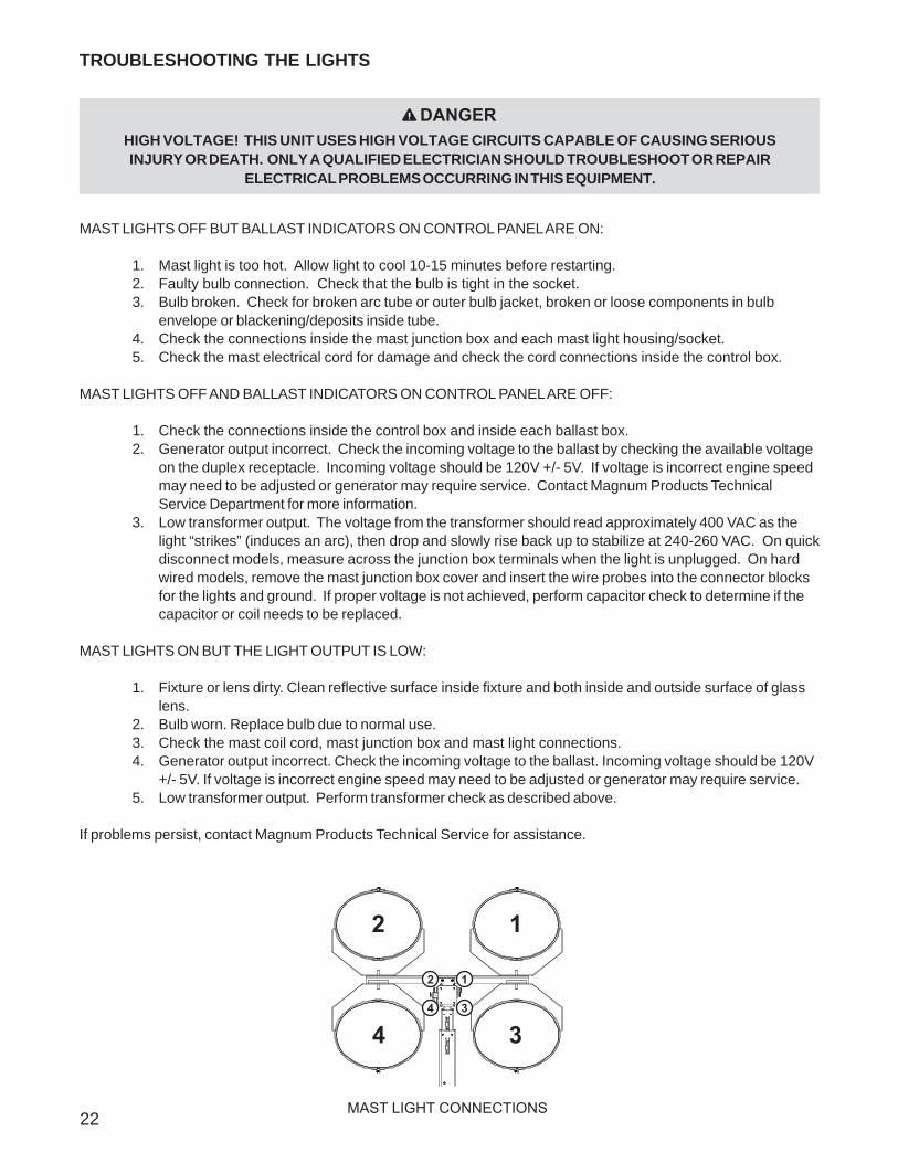
MAST LIGHT CONNECTIONS
23
UNIT DECALS
ITEM NO. PART NO. QTY DESCRIPTION1 12141 1 Decal set, LT eng/safety 4-lang2 11275 1 Decal, Magnum logo w/ web - red vinyl3 12262 1 Decal, 4000/5000 set up 4-lang (manual winch)4 12880 1 Decal, instruction 4000/5000 4-lang (electric winch)5 12140 1 Decal set, common mast 4-lang6 13614 1 Decal, mast junction box wiring - 4 light (for units
with 2, 3 & 5 pos. locking terminal blocks)
www.m-p-llc.com
WARNING
WARNUNG
ADVERTENCIA
ADVERTISSEMENT
STAND CLEAR OF FRONT AND REAR OF MACHINEWHEN MAST IS BEING TILTED UP OR DOWN.
AUFENTHALT INVORDERER ODER HINTERER UMGEBUNGDES GERÄTES VERMEIDEN WÄHREND MAST HOCH ODERNIEDER GESCHWENKT WIRD.
MANTENGASE ALEJADO DE LA PARTE DELANTERA OTRASERA DE LA MAQUINA MIENTRAS QUE SE ESTAPROCEDIENDO A LEVANTAR EL MASTIL A LA POSICION VERTICAL O VOLCARLO A LA POSICION HORIZONTAL.
TENEZ-VOUS A DISTANCE DE L’AVANT ET DEL’ARRIERE DE LA MACHINE PENDANT LE BASCULEMENTDU MAT DANS UN SENS OU DANS L’AUTRE.
ADVERTENCIAWARNUNG
ADVERTISSEMENT
WARNING
1
1
2
Located onElectric Winches
MAST CONTROLMAST-STEUERUNGCONTROL DEL MÁSTILCOMMANDE DE MÂT
TO VERTICAL
TO HORIZONTAL
MAST TELESCOPEMAST-TELESKOP
MAST TELESCOPETÉLESCOPE DE MÂT
TELESCOPE UP
TELESCOPE DOWN
ALWAYS KEEP TENSION ON CABLES! SLACK MAY CAUSE CABLEDAMAGE AND EXCESSIVE WEAR!
¡CSIEMPRE TENSIÓN DE LA SUBSISTENCIA EN LOS CABLES! ¡CCAUSA FLOJA CABLEDAMAGE DE MAYO Y DESGASTE EXCESIVO!
TOUJOURS TENSION DE SUBSISTANCE SUR DES CÂBLES ! CAUSE LÂCHE CABLEDAMAGE DE MAI ET USAGE EXCESSIF !
IMMER UNTERHALT-SPANNUNG AUF KABELN! LOCKERE MAI URSACHE CABLEDAMAGE UND ÜBERMÄSSIGE ABNUTZUNG!
DO NOT MOVE UNIT WITH TOWER UP!UNIT MUST BE MOVED WITH MAST DOWN ANDSECURE IN CRADLE!
NE BOUGEZ PAS D'UNITÉ AVEC LA TOUR EN HAUT! L'UNITÉ PEUT SEULEMENT ÊTRE BOUGÉE AVECLE MÂT EN BAS ET PROTÉGÉ DANS LE BERCEAU!
BEWEGEN SIE EINHEIT MIT DEM TURM NICHT!EINHEIT KANN NUR MIT DEM MAST BEWEGT WERDEN UNTEN UND GESICHERT IN DER WIEGE!
¡NO MUEVA UNIDAD CON TORRE!UNIDAD PUEDE SER SÓLO MOVIDA CON MÁSTIL¡ABAJO Y ASEGURADO EN CUNA!
DANGER
GEFHAR
PELIGRO
DANGER
N'INSTALLEZ PAS L'UNITÉ EN FORT VENT OUPENDANT LES ORAGES ÉLECTRIQUES ! VÉRIFIEZ LES OBSTRUCTIONS AÉRIENNESAVANT UTILISATION !
¡CNO INSTALE LA UNIDAD EN FUERTE VIENTOO DURANTE TORMENTAS ELÉCTRICAS!¡CCOMPRUEBE PARA SABER SI HAYOBSTRUCCIONES DE ARRIBA ANTES DE USAR!
DO NOT SET UP UNIT IN HIGH WIND ORDURING ELECTRICAL STORMS!CHECK FOR OVERHEAD OBSTRUCTIONSBEFORE USING!
DANGER
STELLEN SIE NICHT MASSEINHEIT IM STARKENWIND ODER WÄHREND DER ELEKTRISCHENSTÜRME AUF!ÜBERPRÜFEN SIE AUF OBENLIEGENDEHINDERNISSE, BEVOR SIE VERWENDEN!
GEFHAR
PELIGRO
DANGER
1
1
1
4 44
3 4
3 4
This decal is also located on the
bottom side of mast
1. READ OPERATOR'S MANUAL.2. USE HITCH RATER FOR TRAILER'S "GROSS VEHICLE WEIGHT RATING".3. SECURELY ATTACH TRAILER TO TOW VEHICLE.4. ATTACH SAFETY CHAINS USING A CROSS PATTERN.5. ATTACH BREAKDOWN CHAIN TO VEHICLE.6. CHECK TRAILER LIGHTS.
TOWING INSTRUCTIONSINSTRUCCIONES DE REMOLQUE1. LEA EL MANUAL DEL OPERARIO.2. UTILICE UN ACOPLE CORRECTAMENTE CLASIFICADO PARA LA "CLASE DE PESO BRUTO" DEL VEHICULO DE REMOLQUE3. ASEGURESE DE ACOPLAR CORRECTAMENTE EL REMOLQUE AL VEHICULO DE REMOLQUE.4. FIJE EN CRUZ LAS CADENAS DE SEGURIDAD.5. FIJE EN EL VEHICULO DE REMOLQUE LA CADENA DE DESPRENDIMIENTO.6. CONTROLE LAS LUCES DEL REMOLQUE.
ABSCHLEPPINSTRUKTIONEN1. LIRE LA NOTICE D’EMPLOI.2. UTILISER UN CROCHET D’ATTELAGE CONFORME AU DEBIT NOMINAL DU POIDS BRUT DE VEHICULE DU VEHICULE TRACTEUR.3. ATTACHER LA REMORQUE FERMEMENT AU VEHICULE TRACTEUR.4. ATTACHER LES CHAINES DE SURETE EN UTILISANT UNE METHODE CROISEE.5. ATTACHER LA CHAINE DE REMORQUAGE AU VEHICULE.6. VERIFIER LES LAMPES DE LA REMORQUE.
INSTRUCTIONS DE REMORQUAGE1. BETRIEBSVORSCHRIFT LESEN.2. ANHÄNGEVORRICHTUNG VERWENDEN, DIE DER GESAMTBETRIEBSGEWICHTSKLASSE ENTSPRICHT .3. ANHÄNGER SICHER AM ZUGFAHRZEUG BEFESTIGEN.4. SICHERHEITSKETTEN KREUZWEISE ANBRINGEN.5. ABREISSKETTE AM FAHRZEUG ANBRINGEN.6. ANHÄNGERLEUCHTEN PRÜFEN.
N'ENLEVEZ PAS !
GEFAHR
PELIGRO
DANGER
DANGERDO NOT REMOVE!
ENTFERNEN SIE NICHT!
NO QUITE!
DA
NG
ER
GE
FAH
RP
ELI
GR
OD
AN
GE
R
WA
RN
ING
WA
RN
UN
G
AD
VE
RTE
NC
IA
AD
VE
RTIS
SE
ME
NT
STAND
CLEAR
OF FR
ON
T AND
REAR
OF M
ACH
INE
WH
EN M
AST IS BEING
TILTED U
P OR
DO
WN
.
AUFEN
THALT IN
VOR
DER
ER O
DER
HIN
TERER
UM
GEBU
NG
DES G
ERÄTES VER
MEID
EN W
ÄHR
END
MAST H
OC
H O
DER
NIED
ER G
ESCH
WEN
KT WIR
D.
MAN
TENG
ASE ALEJADO
DE LA PAR
TE DELAN
TERA O
TRASER
A DE LA M
AQU
INA M
IENTR
AS QU
E SE ESTAPR
OC
EDIEN
DO
A LEVANTAR
EL MASTIL A LA PO
SICIO
N
VERTIC
AL O VO
LCAR
LO A LA PO
SICIO
N H
OR
IZON
TAL.
TENEZ-VO
US A D
ISTANC
E DE L’AVAN
T ET DE
L’ARR
IERE D
E LA MAC
HIN
E PEND
ANT LE BASC
ULEM
ENT
DU
MAT D
ANS U
N SEN
S OU
DAN
S L’AUTR
E.
5
5 5
5
Located on inside cover of mast junction box.
6

Located on inside of door:
CERCIÓRESE DE QUE EL INTERRUPTOR PRINCIPAL ESTÉAPAGADO ANTES DE ENCENDER EL MOTOR.
MAKE SURE MAIN CIRCUITBREAKER IS OFF BEFORESTARTING ENGINE.
TURNMAIN
BREAKEROFF
TURNMAIN
BREAKEROFF READ AND UNDERSTAND THE SUPPLIED OPERATOR’S MANUAL
BEFORE OPERATINGTHIS MACHINE. FAILURE TO DO SO INCREASES THE RISK OF INJURY TO YOURSELF OR OTHERS.
LIRE ET COMPRENDRE LA NOTICE D’EMPLOI FOURNIE AVEC LAMACHINE AVANT DE LA METTRE EN SERVICE. A DEFAUT. VOUSAUGMENTERIEZ LE RISQUE DE VOUS EXPOSER ET LES AUTRESA DES BLESSURES.
LEA Y ENTIENDA EL MANUAL DE OPERACION PROVISTO CON ELEQUIPO ANTES DE QUE OPERE ESTE EQUIPO. DE NO HACERSEASI. PODRIA AUMENTAR EL RIESGO DE DAÑOS PERSONALES YA OTRAS PERSONAS.
VOR INBETRIEBNAHME DIESES GERÄTES BEIGEFÜGTE BETRIEBSVOR-SCHRIFT LESEN UND VERSTEHEN. NICHTBEFOLGUNG ERHÖHT DASRISIKO ZU EIGENER VERLETZUNG ODER ANDERER.
ÜBERZEUGEN SIE SICH HAUPTSTROMKREISBRECHERIST VON VORHER STARTMOTOR.
ASSUREZ-VOUS LE CIRCUIT PRINCIPALLE BRISANTEST D'AUPARAVANT MOTEUR DE DÉPART.
WARNUNG
ADVERTENCIA
ADVERTISSEMENT
ADVERTENCIA
ADVERTISSEMENT
WARNUNG
WARNING WARNING
OFF OFFIO
SHUT DOWN/GESCHLOSSEN/ARRÊTÉ/APAGADO
IO I
OIO
IO
IO
IO I
OIO
IO
IO
ALL CIRCUIT BREAKERS OFF!ALLE CIRCUITBREAKERS WEG!TOUS LES DISJONCTEURS AU LOIN ! TODOS LOS INTERRUPTORES APAGADO!
START ENGINE/LASSEN SIE MASCHINE AN/METTEZ EN MARCHE LE MOTEUR/ENCIENDA EL MOTOR.
GLOWPLUG
OFF
RUN
START
RELEASE KEY
LASSEN SIE TASTE LOSLIBÉREZ LA CLEFLANCE LA LLAVE
GLOWPLUG
OFF
RUN
START
ACTIVATE GLOW PLUGS
AKTIVIEREN SIE GLÜHKERZENACTIVEZ LES PRISES DE LUEUR
ACTIVE LOS ENCHUFESDE RESPLANDOR.
GLOWPLUG
OFF
RUN
START
CRANK ENGINE TO START
REIZBARE MASCHINE ZUM ZU BEGINNENMOTEUR DÉTRAQUÉ À COMMENCERPONGA EL MOTOR PARA COMENZAR.
TURN CIRCUIT BREAKERS ON.SCHALTEN SIE CIRCUIT BREAKERS EIN!ALLUMEZ LES DISJONCTEURSGIRE LOS INTERRUPTORES.
1
2
3
4
6
5
STOP ENGINE.STOPPEN SIE MASCHINE.ARRÊTEZ LE MOTEURAPAGUE EL MOTOR.
GLOWPLUG
OFF
RUN
START
BEFORE STARTING THE ENGINE/BEVOR DIE MASCHINE ANGELASSEN WIRDAVANT DE METTRE EN MARCHE LE MOTEUR/ANTES DE ENCENDER EL MOTOR:
ENGINE OPERATION/MASCHINE BETRIEB/OPÉRATION DE MOTEUR/OPERACIÓN DEL MOTOR:
1. CHECK FUEL LEVEL. Überprüfen Sie Kraftstoffniveau. Vérifiez le niveau de carburant. Compruebe el nivel del combustible.2. CHECK ENGINE OIL LEVEL. Überprüfen Sie Triebwerkölstand. Vérifiez le niveau d'huile à moteur. Compruebe el nivel del aceite de motor.
3. CHECK COOLANT LEVEL. Überprüfen Sie Kühlmittelniveau. Vérifiez le niveau de liquide réfrigérant. Compruebe el nivel del liquido refrigerador.4. MAKE SURE MAIN CIRCUIT BREAKER IS OFF. Stellen Sie sicher, daß Hauptschutzschalter aus ist. Assurez-vous que le disjoncteur principal est éteint. Cerciorese de que el interruptor principal esté apagado.
!
IO I
OIO
IO
IO
ALL CIRCUIT BREAKERS OFF!ALLE CIRCUITBREAKERS WEG!TOUS LES DISJONCTEURS AU LOIN ! TODOS LOS INTERRUPTORES APAGADO!
SECURE MAST IN TRANSPORTLOCK BEFORE LIFTING OR TOWING!
DEN MAST VOR DEM ANHEBEN ODERABSCHLEPPEN IN DERTRANSPORTHALTERUNG SICHERN!
VERROUILLEZ SOLIDEMENT LE MATPOUR LE TRANSPORT AVANT DELE HISSER OU DE LE REMORQUER.
ADVERTENCIA
WARNUNG
ADVERTISSEMENT
FIJE EL MASTIL EN LA TRABA DETRANSPORTE ANTES DE REMOLCARO LEVANTAR EL MISMO.
WARNING
CO
NTAC
T WITH
OVER
HEAD
ELECTR
ICAL PO
WER
LINES W
ILL CAU
SE SERIO
US IN
JUR
Y OR
DEATH
.D
O N
OT PO
SITION
LIGH
T TOW
ER U
ND
ER ELEC
TRIC
ALPO
WER
LINES.
KON
TAKT MIT O
BERIR
DISC
HEN
STRO
MFR
EILEITUN
GEN
KANN
ZU SC
HW
EREN
VERLETZU
NG
ENO
DER
TOD
FÜH
REN
. NIEM
ALS BELEUTU
NG
STUR
MU
NTER
ELEKTRISC
HEN
LEITUN
GEN
AUFSTELLEN
.
EL CO
NTAC
TO C
ON
CABLES ELEC
TRIC
OS D
ETEN
DID
O AER
EO C
ON
DU
CIR
A A GR
AVES HER
IDAS O
MU
ERTE. N
UN
CA U
BIQU
E LA TOR
RE D
E LUZ D
EBAJOD
E CABLES ELEC
TRIC
OS D
E TEND
IDO
AEREO
.
TOU
T CO
NTAC
T AVEC D
ES CABLES ELEC
TRIQ
UES
AERIEN
S PEUT PR
OVO
QU
ER D
E SERIEU
SESBLESSU
RES ET M
EME LA M
OR
T. NE PO
SITION
NEZ
PAS LE MAT D
ECLAIR
AGE SO
US D
ES CABLES
ELECTR
IQU
ES AERIEN
S. DA
NG
ER
GE
FAH
R
PE
LIGR
O
CO
MP
LETE
LY LOW
ER
TOW
ER
BE
FOR
E TILTIN
G M
AS
T.TILTIN
G A
N E
XTE
ND
ED
MA
ST C
OU
LD C
AU
SE
SE
RIO
US
INJU
RY O
R D
EATH
.
VOR
DEM
EINSC
HW
ENKEN
DES M
ASTES, BELEU
CH
TUN
GSTU
RM
GAN
Z NIED
ERLASSEN
. EIN
SCH
WEN
KUN
G D
ES VERLÄN
GERTEN
MASTES KAN
N
SCH
WER
E VERLETZU
NG
OD
ER TO
D H
ERVOR
RU
FEN.
BA
JE E
L MA
STIL C
OM
PLE
TAM
EN
TE A
NTE
S D
E
VO
LCA
RLO
A LA PO
SIC
ION
HO
RIZO
NTA
L. EL V
OLC
AR
UN
MA
STIL E
XTE
ND
IDO
PU
ED
E LLE
GA
R A C
AU
SA
R G
RAV
ES
HE
RID
AS
O M
UE
RTE
.
RA
BA
ISS
EZ C
OM
PLE
TEM
EN
T LE M
AT AVAN
T DE
LEB
AS
CU
LER
. LE G
AS
CU
LEM
EN
T D’U
N M
AT DE
PLO
YE
PE
UT P
RO
VO
QU
ER
DE
SE
RIE
US
ES
BLE
SS
UR
ES
ET M
EM
ELA M
OR
T.
DA
NG
ER
DA
NG
ER
GE
FAH
R
PE
LIGR
O
DA
NG
ER
A NON-SECURED, FALLING MAST WILLCAUSE SERIOUS INJURY OR DEATH IF A PERSON IS HIT. TO SECURE MAST, INSERTTHE LOCK BAR INTO MAST MOUNTEDBRACKET THEN INSERT PIN.
EIN UNGESICHERTER HERABFALLENDERMAST KANN SCHWERE, ODERVERLETZUNGEN VERURSACHEN, WENNER AUF EINE PERSON FÄLLT. ZUMSICHERN DES MASTES DIEVERRIEGELUNGSSTANGE IN DIEMASTMONTIERTE HALTERUNG STECKENUND DANN DEN SICHERUNGSSTIFTEINSTECKEN.
UN MASTIL INCORRECTAMENTE FIJADOPODRIA CAUSAR LESIONES SEVERAS OMUERTE AL CAER SOBRE UNA PERSONA.PARA FIJAR EL MASTIL, INTRODUZCAPRIMERO EL PERNO DE BLOQUEODENTRO DE LA PIEZA DE FIJACIONDEL MASTIL Y LUEGO COLOQUE ELPASADOR DE SEGURIDAD.
LA CHUTE D’UN MAT MAL FIXE SURUNE PERSONNE PEUT ENTRAINER DESBLESSURES GRAVES OU LA MORT.POUR FIXER SOLIDEMENT LE MAT,INSEREZ LA BARRE DE VERROUILLAGEDANS LE SUPPORT DU MAT, PUISINSEREZ LA BROCHE.
GEFAHR
PELIGRO
DANGER
DANGER
DANGER
GEFAHRPELIGRODANGER
WARNING
WARNUNG
ADVERTISSEMENT
ADVERTENCIA
WARNUNG
ADVERTISSEMENT
ADVERTENCIA
WARNING
ELECTRICAL STORAGE DEVICE WITHIN. CONTACT A QUALIFIED ELECTRICIANFOR SERVICE OR TO OPEN ELECTRICAL BOX. ELECTRIC SHOCK WILL CAUSESERIOUS INJURY OR DEATH.
ENTHÄLT ELEKTRISCHES SPEICHERGERÄT. ZUR WARTUNG ODER ZUM ÖFFNEN DES ELEKTROGEHÄUSES EINEN GESCHULTEN ELEKTRIKER ZU RATE ZIEHEN. ELEKTRISCHE SCHLÄGE VERURSACHEN SCHWERE ODER TÖDLICHEVERLETZUNGEN.
DISPOSITIVO DE ALMACENAJE ELECTRICO EN EL INTERIOR. PARA TRABAJOSDE MANTENIMIENTO O PARA ABRIR LA CAJA ELECTRICA CONSULTE A UNELECTRICISTA CAPACITADO. SACUDIDAS ELECTRICAS PUEDEN CAUSARSEVERAS LESIONES O MUERTE.
DISPOSITIF ELECTRIQUE DE STOCKAGE A L’INTERIEUR. CONTACTEZ UNELECTRICIEN QUALIFIE POUR REPARER OU OUVRIR LE BOITIER ELECTRIQUE.UNE DECHARGE ELECTRIQUE ENTRAINERA DES BLESSURES GRAVES OULA MORT.
DANGER
DANGER
GEFAHR
PELIGRO
Located onControl Box
Located onManual Holder
1
11
1 1
1
2
2
2
2
2
2
2
2
2
2
2
3
4
UNIT DECALS
24
ITEM NO. PART NO. QTY DESCRIPTION1 12140 1 Decal set, common mast 4-lang2 12141 1 Decal set, LT eng/safety 4-lang3 16488 1 Decal, Magnum logo w/ red stripe4 12142 1 Decal, ground
SECURE MAST IN TRANSPORTLOCK BEFORE LIFTING OR TOWING!
DEN MAST VOR DEM ANHEBEN ODERABSCHLEPPEN IN DERTRANSPORTHALTERUNG SICHERN!
VERROUILLEZ SOLIDEMENT LE MATPOUR LE TRANSPORT AVANT DELE HISSER OU DE LE REMORQUER.
ADVERTENCIA
WARNUNG
ADVERTISSEMENT
FIJE EL MASTIL EN LA TRABA DETRANSPORTE ANTES DE REMOLCARO LEVANTAR EL MISMO.
WARNING
Inside, Front Panel
WARNING
WARNUNG
ADVERTISSEMENTADVERTENCIA
DIESEL DIESEL
DANGERGEFAHRPELIGRODANGER
DANGER
GEFAHRPELIGRODANGER
ADVERTENCIAWARNUNG
ADVERTISSEMENT
WARNING
WARNING
WARNUNG
ADVERTISSEMENT
ADVERTENCIA
WARNUNG
ADVERTISSEMENT
ADVERTENCIA
WARNING
WARNUNG
ADVERTISSEMENT
WARNING
ADVERTENCIA
1 1
1 1
2
22
3
2
2
2 2
2
2
UNIT DECALS
25
ITEM NO. PART NO. QTY DESCRIPTION1 12140 1 Decal set, common mast 4-lang2 12141 1 Decal set, LT eng/safety 4-lang3 16488 1 Decal, Magnum logo w/ red stripe
26
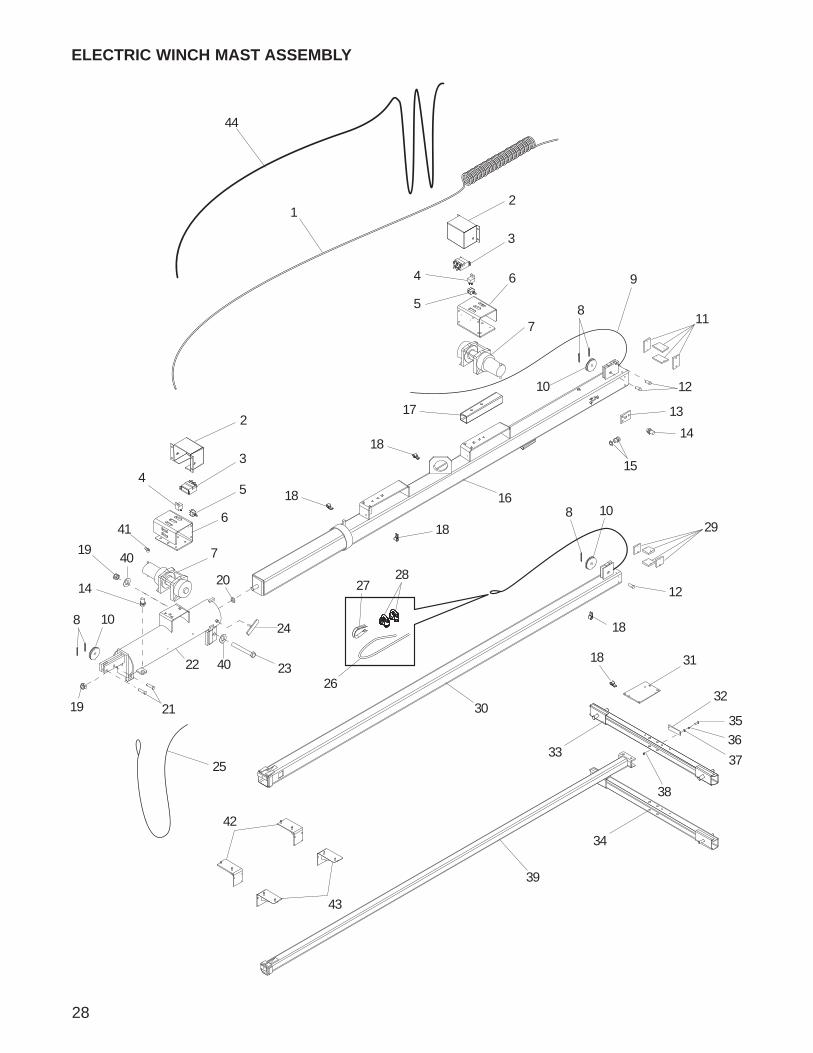
MANUAL WINCH MAST ASSEMBLY
1
2
3
5
6
9
7
8
33
103
4
11
12
13 14
15
16
7
17
18
8
17
19
20
78
25
21
22
23
24
20
2 27
20
20
20
34
35
36
28
29
30
31
32
32
26
27
ITEM NO. PART NO. QTY DESCRIPTION1 11954 1 Coil cord, mast2 16600 2 Winch, manual3 60584 2 Nut, .750-10 nylock G5 yellow zinc4 11902B 1 Weldment, mast tube5 11649Z 1 Weldment, t-bolt6 15292 1 Screw, .750-10X6.500 hx hd SS7 15380 4 Pin, cotter - .125X1.2508 14262 2 Sheave, 3 in.9 60247 1 Washer, flat .75010 14234 2 Pin, clevis .500 x 2.0011 14798 1 Cable, .188 in. X 16 ft. steel w/teardrop12 14151 1 Cable, .188 in. X 11 ft. steel w/ball swedge13 15003 1 Thimble, cable - .18814 15002 2 Clip, wire rope .18815 11933B 1 Weldment, mast - 4.0016 14439 1 Strain relief - .50 NPT, .50 cord, water tight17 15015 3 Pin, clevis .500 x 1.2518 15014 4 Shim, 2 x 3 x .281 GSM19 15013 4 Shim, 2 x 2 x .344 GSM20 16143 5 Clamp, tubing .50021 11934B 1 Weldment, mast - 3.0022 16257B 1 Weldment, mast - 2.0023 12095B 1 Bracket, junction box24 15829 1 Reflector, red25 13527B 1 Weldment, mast crossbar (3/4” studs)26 12751B 1 Weldment, mast crossbar (1/2” studs)27 15006 1 Cable - .188 in. X 27 ft. galv steel w/swedge28 60397 1 Screw, 10-32X1.000 pan hd phil29 60252 2 Washer, split lock #1030 60237 2 Washer, flat #1031 14231 2 Nut, 10-32 hx32 60744 2 Washer, flat .750ID/1.25OD/.06th delrin33 15623 2 Winch handle, 9.00 in long
OPTIONAL FEATURES:34 15612 1 Cable, 16-7 cold mast drape35 12456B 2 Weldment, light storage (rectangular light)
13869B 2 Weldment, light storage (RH oval light)36 12457B 2 Weldment, light storage (rectangular light)
13870B 2 Weldment, light storage (LH oval light)
1500614151
14798
28
1
3
19
24
23
8
22
19
8
10
8 10
11
12
26
29
18
28
21
15
16
2720
25
10
30
39
31
33
32
18
12
18
18
18
5
2
14
13
64
ELECTRIC WINCH MAST ASSEMBLY
42
43
44
9
7
17
3
5
2
6
4
7
14
35
36
37
38
40
40
34
41
29
ITEM NO. PART NO. QTY DESCRIPTION1 11954 1 Coil cord2 12875B 2 Cover, winch contactor3 11293 2 Contactor, electric winch - warn4 65049 2 Relay, 12V 30/40A N.O. w/diode5 65707 2 Switch, toggle - SPDT spring weatherproof6 12872B 2 Bracket, winch mounting7 12874 2 Winch, electric - 770 lb. hoist8 15380 5 Pin, cotter - .125X1.2509 15006 1 Cable, .188 in. x 27 ft. w/ball swedge10 14262 3 Sheave, 3 in.11 15014 4 Shim, 2 x 3 x .281 GSM12 15015 3 Pin, clevis .500 x 1.2513 65510B 1 Bracket, sensor mtg14 65511 2 Sensor, proximity15 14439 1 Strain relief- .50 NPT, .50 cord16 12085B 1 Weldment, 4.00 mast - Electric Winch17 11967B 1 Channel, electric winch mount18 16143 2 Clamp, tubing .50019 60584 2 Nut, .750-10 nylock G5 yellow zinc20 60247 1 Washer, flat .75021 14234 2 Pin, clevis .500 x 2.0022 12876B 1 Weldment, mast tube - Electric Winch23 15292 1 Screw, 750-10 x 6.50 hx hd SS24 11649Z 1 Weldment, t-bolt25 14798 1 Cable - .188 in. X 16 ft. steel w/teardrop26 14151 1 Cable - .188 in. X 11 ft. steel w/swedge27 15003 1 Thimble, cable - .18828 15002 2 Clip, wire rope - .188 single saddle29 15013 4 Shim, 2 x 2 x .344 GSM30 12084B 1 Weldment, 3.00 mast31 12095 1 Bracket, junction box32 15829 1 Reflector, red33 13527B 1 Weldment, mast crossbar (3/4” studs)34 12751B 1 Weldment, mast crossbar (1/2” stud)35 60397 1 Screw, 10-32X1.000 pan hd phil36 60252 2 Washer, split lock #1037 60237 2 Washer, flat #1038 14231 2 Nut, 10-32 hx39 16257B 1 Weldment, mast - 2”40 60744 2 Washer, flat .750ID/1.25OD/.06th delrin41 12922 4 Boot, battery cable - red
OPTIONAL FEATURES:42 12456B 2 Weldment, light storage (rectangular light)
13869B 2 Weldment, light storage (RH oval light)43 12457B 2 Weldment, light storage (rectangular light)
13870B 2 Weldment, light storage (LH oval light)44 15612 1 Cable, 16-7 cold mast drape
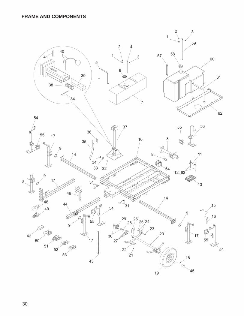
30
FRAME AND COMPONENTS
1
2 4
3
12 3
5
6
7
89
9
10
11
12, 63
13
14
14
16
17
9
17
9
17
18
19
20
15
2122
24
23
2526
27
2829
30
31
31
3233
34
34
3637
38
39
40
35
41
42
44
45
43
46
47
48
49
5051
5253
54
55
55
54
55
54
55
57 58
59
60
61
62
56
8
9
64
31
ITEM NO. PART NO. QTY DESCRIPTION1 16270 1 Fitting, .375MNPT to .250 FNPT straight2 16271 1 Fitting, 90-.250NPTX.188 barb3 15142 1 Fitting, strt-.250NPTX.312 barb4 13500 1 Fuel, pick-up tube - 14.00 in.5 13616B 2 Strap, fuel tank - 30 gal tank w/sump6 12137 1 Cap, fuel tank - vent 3.5 dia grn7 12646 1 Tank, fuel - 30 gal poly8 14223 2 Jack, sidewind - 2000lb - snap ring mounted9 14326 5 Ring, retaining10 11563B 1 Weldment, chassis11 14682 1 Bracket, battery hold-down12 60820 2 Bolt, J - .250-20 X 9.0013 14145 1 Battery tray14 12408Z 2 Weldment, outrigger15 23505 4 Cable, pin tether 12"16 23256 4 Pin, jack - 2000# tube mtd17 14222 3 Jack, top wind - 2000lb - snap ring mounted18 60096 10 Nut, .500-20 wheel lug19 15976 2 Wheel, ST175/80D13 bias tubeless 5 hole20 16593 1 Axle - 2200 lb. 56TC 45SC21 11279 8 Axis axle nut (Ubolt) 3500lb22 11278 2 Axis axle tie - plate 3500lb23 60503 6 Screw, .562-18 hx shackle GR524 19637 4 Plate, shackle bracket25 60504 6 Nut, .562-18 hx shackle lock26 11277 4 Axis axle u-bolt 3500lb27 60674 10 Stud, wheel - .500-20 GR828 13000 2 Axis axle seal - 2200#29 11276 2 Axis axle hub w/races 3500lb30 11511 4 Axis axle roller bearing31 14324 2 Kit, plunger32 15015 1 Pin, clevis - .500 DIA X 1.25033 14261 1 Sheave - 2 in.34 15380 2 Pin, cotter - .125X1.25035 14845B 1 Spring, kickback - 50 lb.36 11554Z 1 Spacer plate - kick-back spring37 11057B 1 Weldment, mast post38 14275 1 Spring - 2.7539 14663Z 1 Bar, latch40 14403 1 Pin, cotterless - .312 X 1.000
60707 1 Chain, sash - no 8 stainless steel60706 1 Ring, split - 1.00 SS
41 15165 1 Pin, roll - .250X1.250 plain42 16830 1 Coupler - 2.00 ball/2.50 channel43 23367 1 Chain, safety - 7,800 lbs. rated44 12420B 1 Weldment, removable tongue45 12460 2 Axle wheel bearing cap
OPTIONAL FEATURES:46 12235B 1 Weldment, spare tire holder47 11368B 1 Weldment, tongue - adjustable hitch w/storage48 19335B 1 Hitch, pintle eye (adj) - 3.00 ID49 19518 1 Coupler, adjustable - 2 in. ball
Continued on next page.
colsonmader
Comment on Text
Steve J. said this nut is good on these units, DO NOT change to 11203.
colsonmader
Cross-Out
colsonmader
Typewritten Text
11202
colsonmader
Cross-Out
colsonmader
Typewritten Text
11201
colsonmader
Cross-Out
colsonmader
Inserted Text
2200lb
colsonmader
Cross-Out
colsonmader
Inserted Text
2200lb
colsonmader
Cross-Out
even though the description for this part is 3500lb, it is used for the 2200lb trailer as well. To avoid confusion, just remove the 3500lb part of the description.
colsonmader
Sticky Note
Item 22 and 26 changes as per Tara S. and Steve J.
colsonmader
Cross-Out
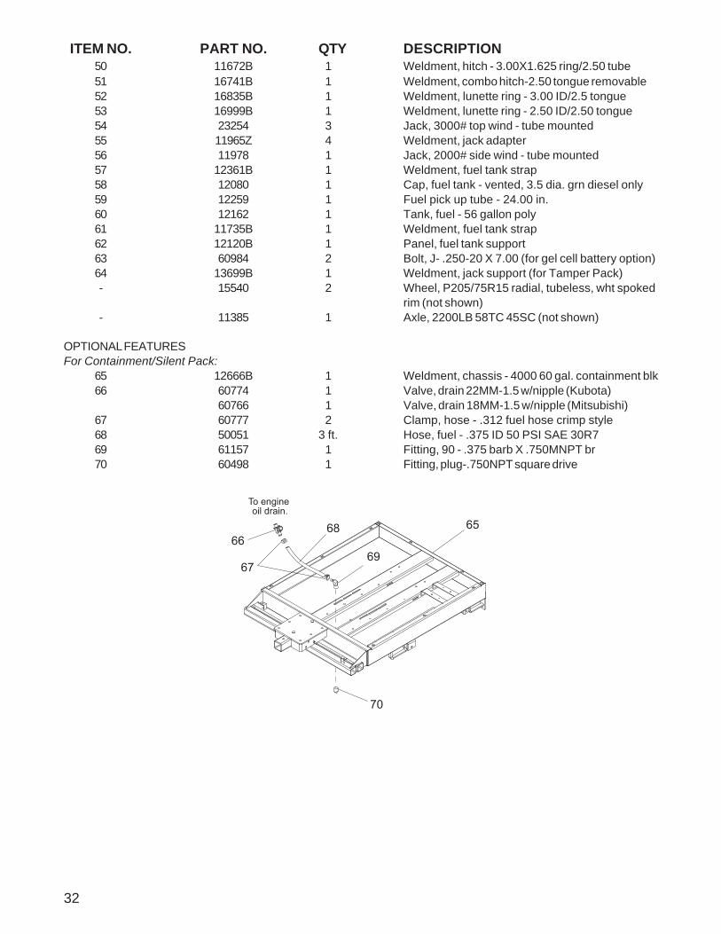
ITEM NO. PART NO. QTY DESCRIPTION50 11672B 1 Weldment, hitch - 3.00X1.625 ring/2.50 tube51 16741B 1 Weldment, combo hitch-2.50 tongue removable52 16835B 1 Weldment, lunette ring - 3.00 ID/2.5 tongue53 16999B 1 Weldment, lunette ring - 2.50 ID/2.50 tongue54 23254 3 Jack, 3000# top wind - tube mounted55 11965Z 4 Weldment, jack adapter56 11978 1 Jack, 2000# side wind - tube mounted57 12361B 1 Weldment, fuel tank strap58 12080 1 Cap, fuel tank - vented, 3.5 dia. grn diesel only59 12259 1 Fuel pick up tube - 24.00 in.60 12162 1 Tank, fuel - 56 gallon poly61 11735B 1 Weldment, fuel tank strap62 12120B 1 Panel, fuel tank support63 60984 2 Bolt, J- .250-20 X 7.00 (for gel cell battery option)64 13699B 1 Weldment, jack support (for Tamper Pack)- 15540 2 Wheel, P205/75R15 radial, tubeless, wht spoked
rim (not shown)- 11385 1 Axle, 2200LB 58TC 45SC (not shown)
OPTIONAL FEATURESFor Containment/Silent Pack:
65 12666B 1 Weldment, chassis - 4000 60 gal. containment blk66 60774 1 Valve, drain 22MM-1.5 w/nipple (Kubota)
60766 1 Valve, drain 18MM-1.5 w/nipple (Mitsubishi)67 60777 2 Clamp, hose - .312 fuel hose crimp style68 50051 3 ft. Hose, fuel - .375 ID 50 PSI SAE 30R769 61157 1 Fitting, 90 - .375 barb X .750MNPT br70 60498 1 Fitting, plug-.750NPT square drive
32
To engine oil drain.
70
6566
67
68
69
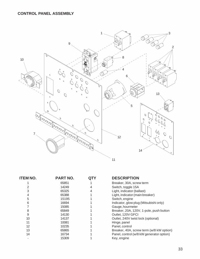
ITEM NO. PART NO. QTY DESCRIPTION1 65851 1 Breaker, 30A, screw term2 14249 4 Switch, toggle 15A3 65325 4 Light, indicator (ballast)4 65388 1 Light, indicator (main breaker)5 15195 1 Switch, engine6 16694 1 Indicator, glow plug (Mitsubishi only)7 15085 1 Gauge, hourmeter8 65849 1 Breaker, 20A, 120V, 1-pole, push button9 14130 1 Outlet, 120V GFCI10 14137 1 Outlet, 240V twist lock (optional)11 10081 1 Hinge, panel12 10235 1 Panel, control13 65865 1 Breaker, 40A, screw term (w/8 kW option)14 16734 1 Panel, control (w/8 kW generator option)- 15309 1 Key, engine
11
4
8
9
12
1
2
3
5
6
7
10
CONTROL PANEL ASSEMBLY
13
14
33
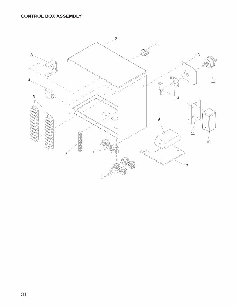
12
3
4
5
1
76
CONTROL BOX ASSEMBLY
8
9
10
11
12
13
14
34
ITEM NO. PART NO. QTY DESCRIPTION1 14202 5 Strain relief - .375 Romex w/nut2 14257B 1 Box, control3 14201 1 Relay, auto shutdown4 14841 1 Breaker, 10A5 14203 2 Strip, terminal6 14204 1 Bar, ground7 14219 2 Strain relief - .75 Romex w/nut
OPTIONAL FEATURES:8 12429B 1 Bracket, battery charger9 65326 1 Charger, battery - 2 amp, 3 stage10 11947 1 Light, interior with switch11 11949B 1 Bracket, control box light mount12 65498 1 Switch, disconnect13 11929B 1 Bracket, battery lock-out switch14 65499 1 Switch, lockout lever kit
35
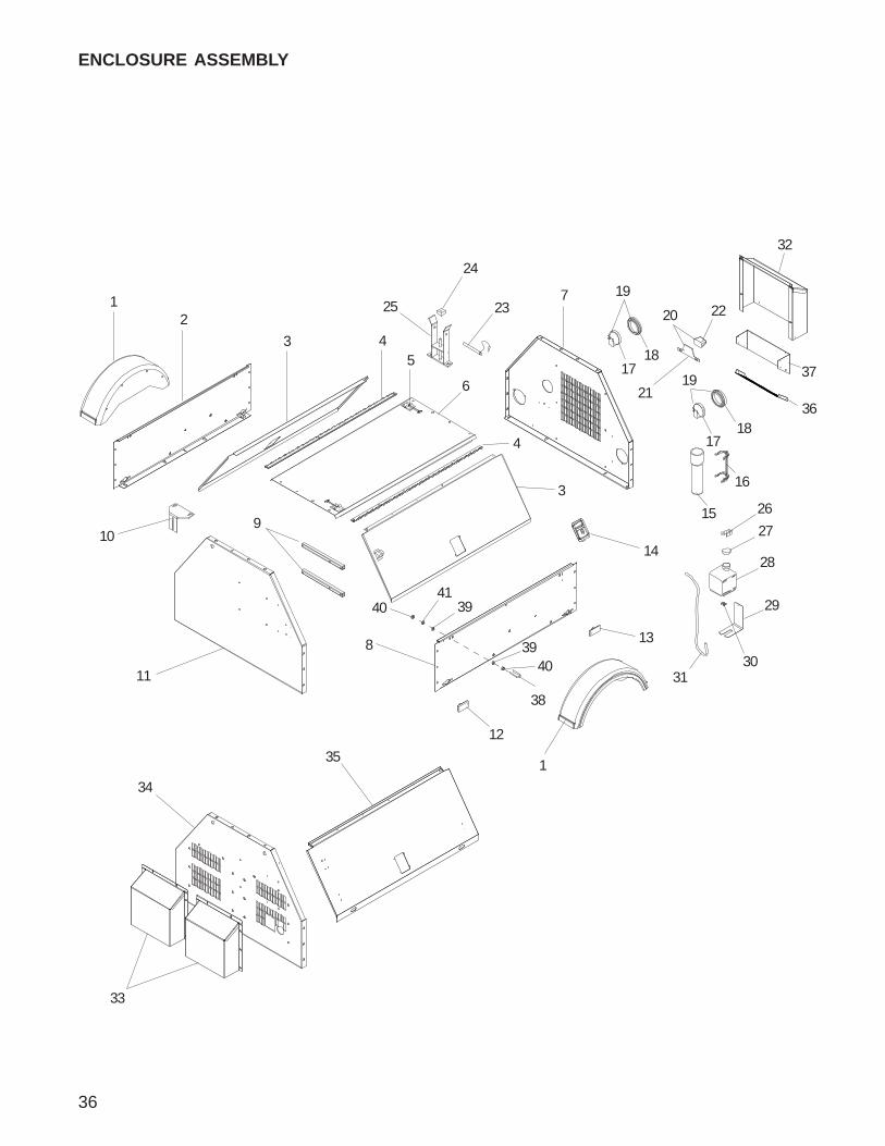
36
ENCLOSURE ASSEMBLY
3
8
1
12
21
4
9
7
10
35
34
11
15
16
6
13
3
4 1718
19
14
1718
19
20
21
22
32
23
24
25
5
33
28
27
26
3130
29
39
38
37
36
4041
39
40
37
ITEM NO. PART NO. QTY DESCRIPTION1 16560 2 Fender, plastic - 13 in. tire2 12025W 1 Panel, right side sheetmetal3 16591 2 Panel, door4 16598 2 Hinge, door - .188 pin, 48.5 long5 12605 2 Door latch SS6 16538W 1 Panel, top7 11684W 1 Panel, rear8 11677W 1 Panel, left side9 11543B 2 Spacer, control box10 14459B 1 Bracket, door adjustment11 12012W 1 Panel, front sheetmetal12 65407 2 Light, clearance marker - amber13 65406 2 Light, clearance marker - red14 15123 2 Latch, paddle w/ 7 lb. spring15 11121 1 Tube, black manual holder16 11222 1 Bracket, manual holder17 10220 2 Light, rear tail/turn18 10221 2 Grommet, rear light, rubber 4.5”19 10219 2 Assy, rear tail/turn light, 3-wire with plug20 10223 1 Assy, license plate light/bracket, 2-wire21 10224 1 Bracket, license plate22 10225 1 Light, license bracket23 11292 1 Pin, mast cradle w/chain & hook24 11935 1 Pad, rubber - 2.00 X 2.00 X 1.0025 11753Z 1 Weldment, cradle26 19714 1 Cap, overflow bottle27 19726 1 Clamp, overflow bottle28 20287 1 Jug, overflow 2 qt (.5 gal)29 22419B 1 Bracket, support overflow jug .5 gal30 60777 1 Clamp, hose - .312 fuel hose crimp style31 19220 1 Hose, overflow- 14410 1 Assembly, overflow jug 1.5 qt. (items 30-35)- 11382W 1 Panel, side - right w/15” tire (opt, not shown)- 11383W 1 Panel, side - left w/15” tire (opt, not shown)- 11381 2 Fender, plastic - 15 in. tire (opt, not shown)
OPTIONAL FEATURESFor Containment/Silent Pack:
32 12189W 1 Duct, radiator guard33 16469W 2 Duct, front34 12754W 1 Panel, front 4000 containment35 16739W 2 Panel, door - U bolt lock
For Tamper Pack:36 12837W 1 Grate, duct - white37 13868W 1 Panel, duct grate bracket - tamper pack38 60200 2 Bolt, U .250-20 X .750 X 1.2539 60243 8 Washer, .250 flat .735/.060 USS40 60284 8 Nut, .250-20 hex G541 60286 4 Washer, .250 split lock
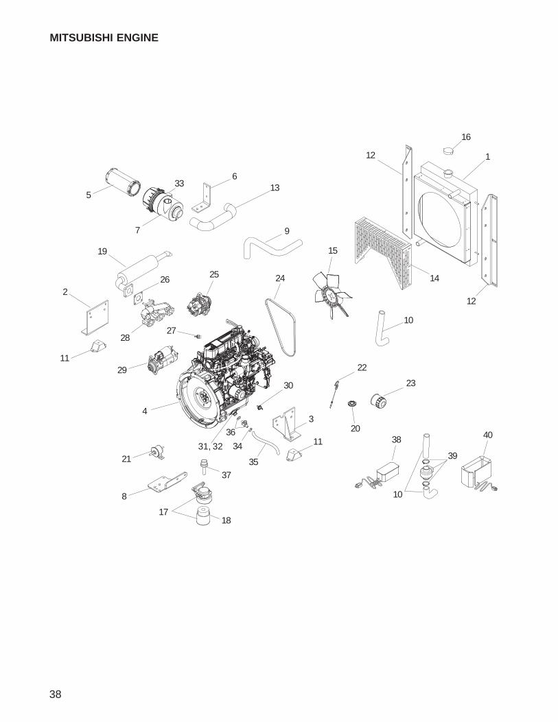
38
MITSUBISHI ENGINE
1
7
3
5
6
4
2
9
8
10
11
11
12
12
16
17
15
20
13
14
21 39
38 40
23
2425
22
27
19
18
29
30
36
26
28
31, 32
37
10
33
34
35
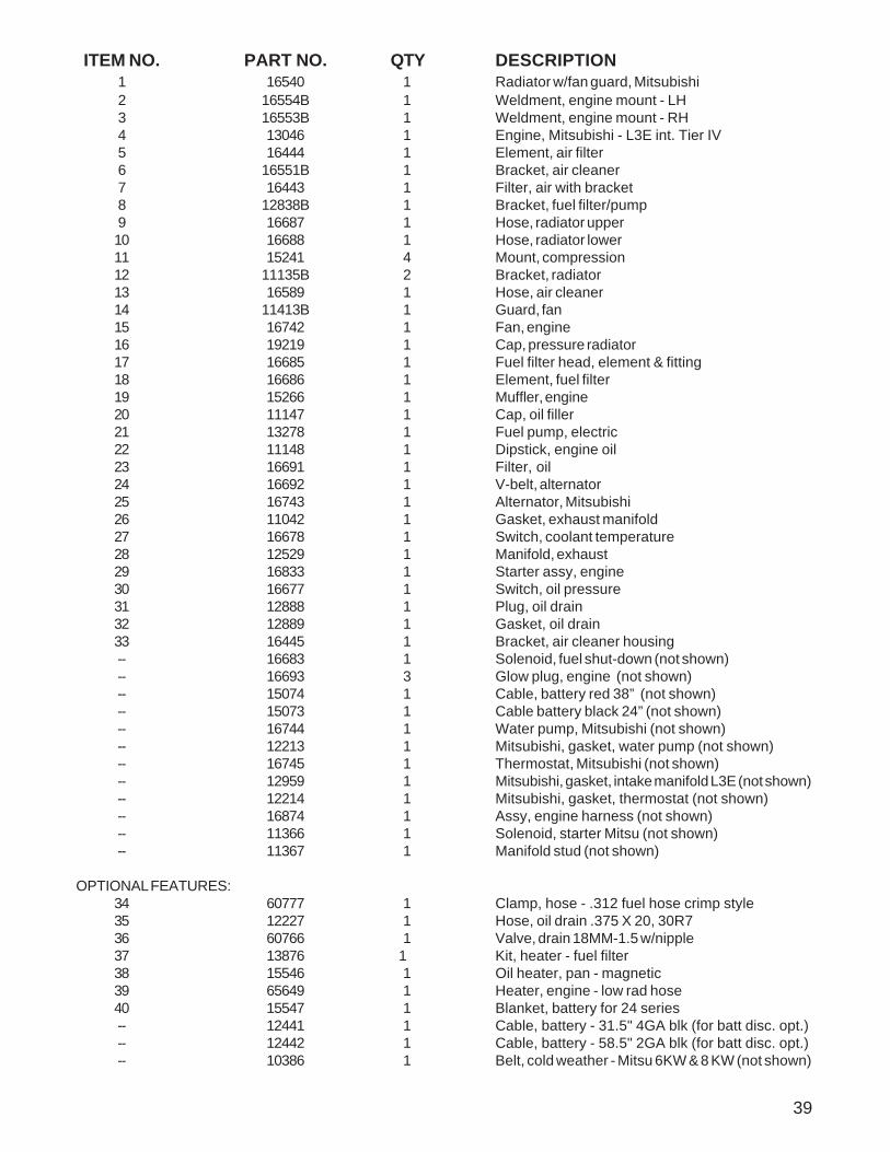
39
ITEM NO. PART NO. QTY DESCRIPTION1 16540 1 Radiator w/fan guard, Mitsubishi2 16554B 1 Weldment, engine mount - LH3 16553B 1 Weldment, engine mount - RH4 13046 1 Engine, Mitsubishi - L3E int. Tier IV5 16444 1 Element, air filter6 16551B 1 Bracket, air cleaner7 16443 1 Filter, air with bracket8 12838B 1 Bracket, fuel filter/pump9 16687 1 Hose, radiator upper10 16688 1 Hose, radiator lower11 15241 4 Mount, compression12 11135B 2 Bracket, radiator13 16589 1 Hose, air cleaner14 11413B 1 Guard, fan15 16742 1 Fan, engine16 19219 1 Cap, pressure radiator17 16685 1 Fuel filter head, element & fitting18 16686 1 Element, fuel filter19 15266 1 Muffler, engine20 11147 1 Cap, oil filler21 13278 1 Fuel pump, electric22 11148 1 Dipstick, engine oil23 16691 1 Filter, oil24 16692 1 V-belt, alternator25 16743 1 Alternator, Mitsubishi26 11042 1 Gasket, exhaust manifold27 16678 1 Switch, coolant temperature28 12529 1 Manifold, exhaust29 16833 1 Starter assy, engine30 16677 1 Switch, oil pressure31 12888 1 Plug, oil drain32 12889 1 Gasket, oil drain33 16445 1 Bracket, air cleaner housing-- 16683 1 Solenoid, fuel shut-down (not shown)-- 16693 3 Glow plug, engine (not shown)-- 15074 1 Cable, battery red 38” (not shown)-- 15073 1 Cable battery black 24” (not shown)-- 16744 1 Water pump, Mitsubishi (not shown)-- 12213 1 Mitsubishi, gasket, water pump (not shown)-- 16745 1 Thermostat, Mitsubishi (not shown)-- 12959 1 Mitsubishi, gasket, intake manifold L3E (not shown)-- 12214 1 Mitsubishi, gasket, thermostat (not shown)-- 16874 1 Assy, engine harness (not shown)-- 11366 1 Solenoid, starter Mitsu (not shown)-- 11367 1 Manifold stud (not shown)
OPTIONAL FEATURES:34 60777 1 Clamp, hose - .312 fuel hose crimp style35 12227 1 Hose, oil drain .375 X 20, 30R736 60766 1 Valve, drain 18MM-1.5 w/nipple37 13876 1 Kit, heater - fuel filter38 15546 1 Oil heater, pan - magnetic39 65649 1 Heater, engine - low rad hose40 15547 1 Blanket, battery for 24 series-- 12441 1 Cable, battery - 31.5" 4GA blk (for batt disc. opt.)-- 12442 1 Cable, battery - 58.5" 2GA blk (for batt disc. opt.)-- 10386 1 Belt, cold weather - Mitsu 6KW & 8 KW (not shown)
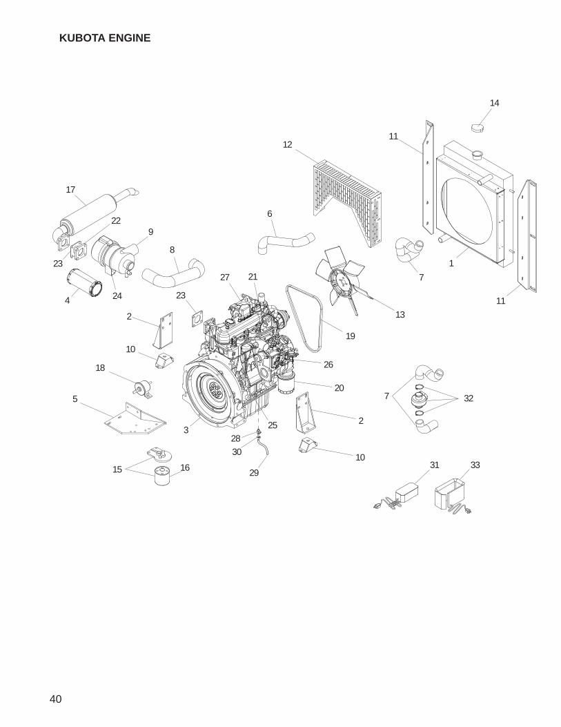
40
KUBOTA ENGINE
1
9
8
10
7
3
5
6
4
2
11
11
10
2
17
14
13
15
12
16
18
19
20
21
22
23
2324
25
26
27
28
29
30
33
32
31
7

41
ITEM NO. PART NO. QTY DESCRIPTION1 16540 1 Radiator, with fan guard2 12338B 2 Weldment, engine mount3 12286 1 Engine, Kubota D9054 16444 1 Element, air filter5 13483B 1 Weldment, filter bracket6 16687 1 Hose, radiator upper7 12350 1 Hose, radiator lower8 16589 1 Hose, air cleaner9 16443 1 Filter, air with bracket10 15241 4 Compression mount11 11135B 2 Bracket, radiator12 11413B 1 Fan Guard13 15495 1 Kubota D905 pusher fan14 19219 1 Cap, pressure radiator 14 psi15 13481 1 Kubota fuel filter assembly, D90516 13515 1 Fuel filter element17 15021 1 Muffler, engine18 13278* 1 Kubota, fuel pump, electric19 11628 1 Kubota D905 V-belt20 15146 1 Filter, oil21 12484 1 Cap, oil filler22 11475 1 Flange, exhaust23 11042 2 Gasket, exhaust manifold24 16445 1 Bracket, air cleaner housing25 12483 1 Dipstick, engine oil26 13018 1 Solenoid, fuel shutdown (2 wire)27 12486 1 Alternator-- 13526 1 Kubota, joint eye, double port (not shown)-- 15375 1 Switch, oil pressure (not shown)-- 14099 1 Switch, coolant temperature (not shown)-- 15074 1 Cable, battery red 38” (not shown)-- 15073 1 Cable, battery black 24" (not shown)-- 65996 1 Assy, engine harness (not shown)* SEE NOTE 3 Glow plug, engine (not shown)* SEE NOTE 1 Starter, engine (not shown)* SEE NOTE 1 Kubota, water pump (not shown)* SEE NOTE 1 Kubota, water pump gasket (not shown)* SEE NOTE 1 Thermostat assy, (not shown)
*NOTE: Some Kubota engine parts are serial number specific. Please contact Kubota Engine America Corp. orthe Magnum Products Technical Service Department at 1-800-926-9768 for information regarding engine parts.
OPTIONAL FEATURES:28 60774 1 Valve, drain 22MM-1.5 w/nipple29 12227 1 Hose, oil drain .375 X 20, 30R730 60777 1 Clamp, hose - .312 fuel hose crimp style31 15546 1 Oil heater, pan - magnetic32 65649 1 Heater, engine - low rad hose33 15547 1 Blanket, battery for 24 series-- 11930 1 Cable, battery - 19" 4ga blk w/heat shrink 3/8"(for
batt disc. opt.) (not shown)
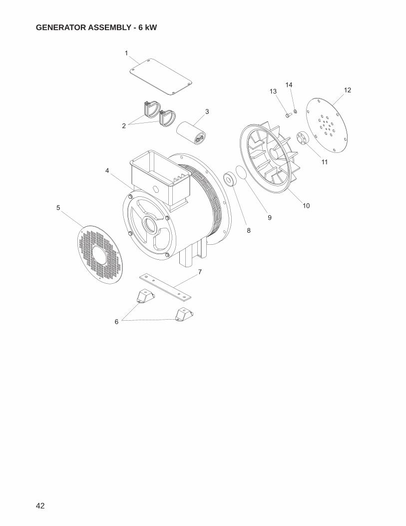
42
GENERATOR ASSEMBLY - 6 kW
1
2
4
3
5
6
7
8
9
10
11
121314
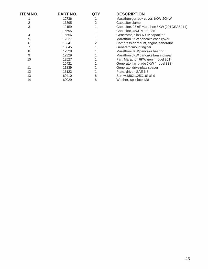
43
ITEM NO. PART NO. QTY DESCRIPTION1 12736 1 Marathon gen box cover, 6KW-20KW2 16395 2 Capacitor clamp3 12159 1 Capacitor, 25 uF Marathon 6KW (201CSA5411)
15695 1 Capacitor, 45uF Marathon4 16556 1 Generator, 6 kW 60Hz capacitor5 12327 1 Marathon 6KW pancake case cover6 15241 2 Compression mount, engine/generator7 15045 1 Generator mounting bar8 12328 1 Marathon 6KW pancake bearing9 12329 1 Marathon 6KW pancake bearing seal10 12527 1 Fan, Marathon 6KW gen (model 201)
16421 1 Generator fan blade 6KW (model 332)11 11339 1 Generator drive plate spacer12 16123 1 Plate, drive - SAE 6.513 60410 6 Screw, M8X1.25X16 hx hd14 60029 6 Washer, split lock M8
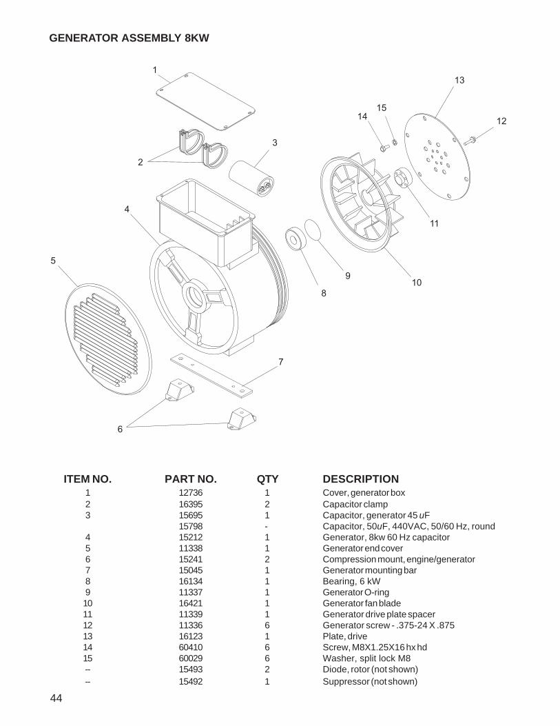
44
ITEM NO. PART NO. QTY DESCRIPTION1 12736 1 Cover, generator box2 16395 2 Capacitor clamp3 15695 1 Capacitor, generator 45 uF
15798 - Capacitor, 50uF, 440VAC, 50/60 Hz, round4 15212 1 Generator, 8kw 60 Hz capacitor5 11338 1 Generator end cover6 15241 2 Compression mount, engine/generator7 15045 1 Generator mounting bar8 16134 1 Bearing, 6 kW9 11337 1 Generator O-ring10 16421 1 Generator fan blade11 11339 1 Generator drive plate spacer12 11336 6 Generator screw - .375-24 X .87513 16123 1 Plate, drive14 60410 6 Screw, M8X1.25X16 hx hd15 60029 6 Washer, split lock M8-- 15493 2 Diode, rotor (not shown)-- 15492 1 Suppressor (not shown)
GENERATOR ASSEMBLY 8KW
1
2
4
3
5
6
7
8
910
11
12
13
1415
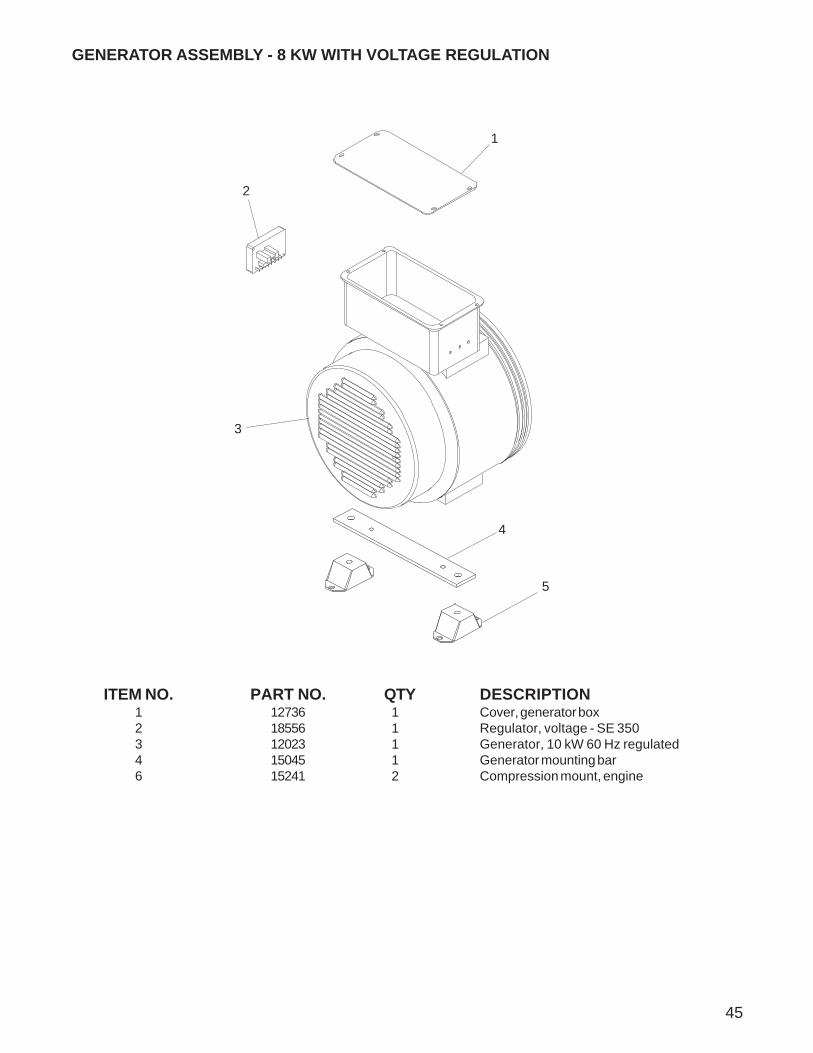
45
GENERATOR ASSEMBLY - 8 KW WITH VOLTAGE REGULATION
3
5
2
1
4
ITEM NO. PART NO. QTY DESCRIPTION1 12736 1 Cover, generator box2 18556 1 Regulator, voltage - SE 3503 12023 1 Generator, 10 kW 60 Hz regulated4 15045 1 Generator mounting bar6 15241 2 Compression mount, engine
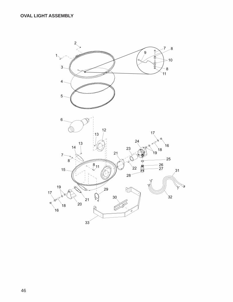
OVAL LIGHT ASSEMBLY
31
3
4
1
2
6
8
5
7
11
12
10
9
8
1314
13
21
17
19
1618
278 11
8
2021
24
25
15 22
7
1719
1618
23
26
33
28
3230
29
46

ITEM NO. PART NO. QTY DESCRIPTION1 60304 1 Screw, M5 x 25 pan hd phillips2 60447 1 Nut, M5 nylock3 13367 1 Assembly, aluminum ring4 13369 1 Lens, glass oval5 13373 1 Gasket, lens oval6 11391 1 Bulb, 1000W MH short length7 13399 2 Screw, M4 x 18 pan hd phillips8 60067 4 Washer, #10 flat .435/.060 SS9 13370 1 Assembly, tether10 13372 2 Washer, #4 nylon11 60051 2 Nut, M4 nylock12 13376 1 Bracket, socket end plate13 13388 10 Screw, M5 x 12 slotted hex w/flange14 13377 1 Bracket, end plate15 13366 1 Housing16 60307 2 Nut, 500-13 nylk G5 ZC17 60309 2 Washer, .500 flat 1.060/.090 ZC SAE18 13392 2 Stud, trunnion19 13390 4 Washer, nylon (for part number 13392)20 13374 1 Support, housing/trunnion21 13378 2 Gasket, silicone22 13393 2 Screw, M5 x 12 phillips green23 13381 1 Socket, bulb24 13375 1 Support, housing/trunnion25 15861 1 Nut, special, .500 NPT lock (LN101SC)26 13386 1 Fitting, nipple27 13387 1 Connector, weather tight28 15864 1 Strain relief, .50 NPT watertight .270/.464 ID29 13892 1 Support, bulb - oval light30 13403 4 Handle, T - oval light (wing nut)31 13383 1 Cord, power quick disconnect32 13438 1 Cord, power hard wired33 13368 1 Trunnion, oval light-- 13311 4 Assembly, light fixture - 1000W MH hard wired
oval (items 1-30, 32)-- 13312 1 Assy, light fixture - 1000W MH quick disc.oval
(items 1-31)
47
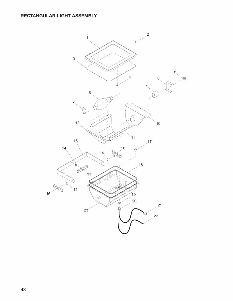
48
12
4
3
5
6
7
8
9
10
11
12
13
14
1414
16
1617
18
19
20
15
21
2223
RECTANGULAR LIGHT ASSEMBLY
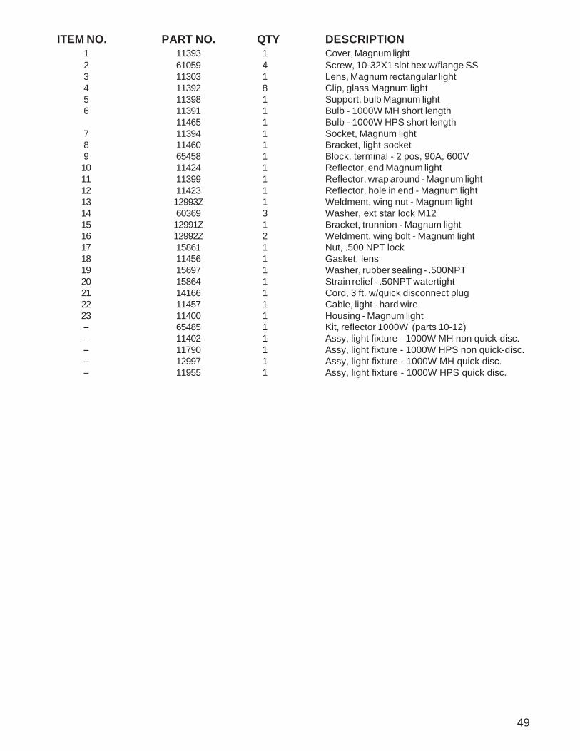
49
ITEM NO. PART NO. QTY DESCRIPTION1 11393 1 Cover, Magnum light2 61059 4 Screw, 10-32X1 slot hex w/flange SS3 11303 1 Lens, Magnum rectangular light4 11392 8 Clip, glass Magnum light5 11398 1 Support, bulb Magnum light6 11391 1 Bulb - 1000W MH short length
11465 1 Bulb - 1000W HPS short length7 11394 1 Socket, Magnum light8 11460 1 Bracket, light socket9 65458 1 Block, terminal - 2 pos, 90A, 600V10 11424 1 Reflector, end Magnum light11 11399 1 Reflector, wrap around - Magnum light12 11423 1 Reflector, hole in end - Magnum light13 12993Z 1 Weldment, wing nut - Magnum light14 60369 3 Washer, ext star lock M1215 12991Z 1 Bracket, trunnion - Magnum light16 12992Z 2 Weldment, wing bolt - Magnum light17 15861 1 Nut, .500 NPT lock18 11456 1 Gasket, lens19 15697 1 Washer, rubber sealing - .500NPT20 15864 1 Strain relief - .50NPT watertight21 14166 1 Cord, 3 ft. w/quick disconnect plug22 11457 1 Cable, light - hard wire23 11400 1 Housing - Magnum light-- 65485 1 Kit, reflector 1000W (parts 10-12)-- 11402 1 Assy, light fixture - 1000W MH non quick-disc.-- 11790 1 Assy, light fixture - 1000W HPS non quick-disc.-- 12997 1 Assy, light fixture - 1000W MH quick disc.-- 11955 1 Assy, light fixture - 1000W HPS quick disc.
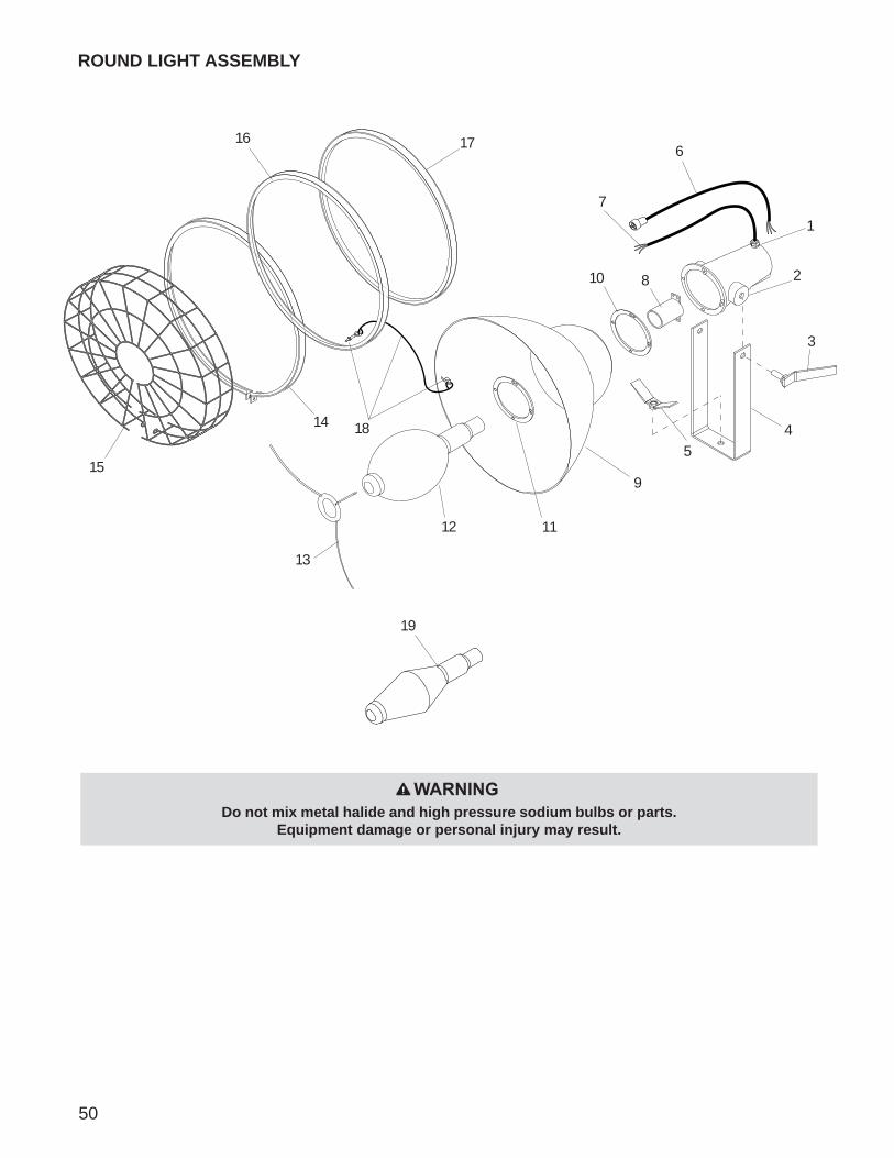
50
ROUND LIGHT ASSEMBLY
1
2
3
5
7
810
9
1112
13
17
14
15
418
616
Do not mix metal halide and high pressure sodium bulbs or parts.Equipment damage or personal injury may result.
WARNING
19
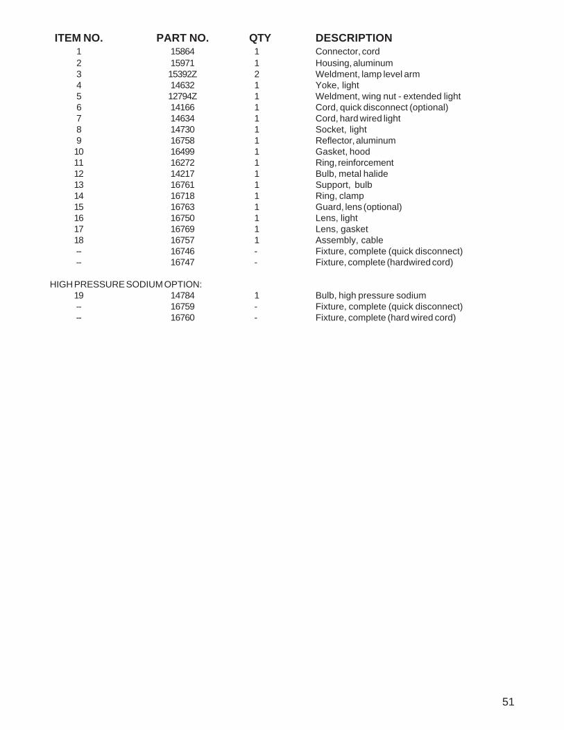
51
ITEM NO. PART NO. QTY DESCRIPTION1 15864 1 Connector, cord2 15971 1 Housing, aluminum3 15392Z 2 Weldment, lamp level arm4 14632 1 Yoke, light5 12794Z 1 Weldment, wing nut - extended light6 14166 1 Cord, quick disconnect (optional)7 14634 1 Cord, hard wired light8 14730 1 Socket, light9 16758 1 Reflector, aluminum10 16499 1 Gasket, hood11 16272 1 Ring, reinforcement12 14217 1 Bulb, metal halide13 16761 1 Support, bulb14 16718 1 Ring, clamp15 16763 1 Guard, lens (optional)16 16750 1 Lens, light17 16769 1 Lens, gasket18 16757 1 Assembly, cable-- 16746 - Fixture, complete (quick disconnect)-- 16747 - Fixture, complete (hardwired cord)
HIGH PRESSURE SODIUM OPTION:19 14784 1 Bulb, high pressure sodium-- 16759 - Fixture, complete (quick disconnect)-- 16760 - Fixture, complete (hard wired cord)

52
3
4
7
811
12
1
2
5
6
9
1013
14
SPERO RECTANGULAR LIGHT ASSEMBLY
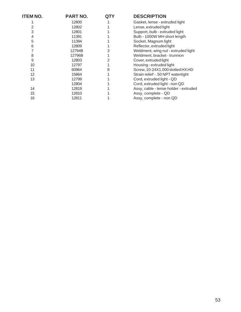
53
ITEM NO. PART NO. QTY DESCRIPTION1 12800 1 Gasket, lense - extruded light2 12802 1 Lense, extruded light3 12801 1 Support, bulb - extruded light4 11391 1 Bulb - 1000W MH short length5 11394 1 Socket, Magnum light6 12809 1 Reflector, extruded light7 12794B 3 Weldment, wing nut - extruded light8 12796B 1 Weldment, bracket - trunnion9 12803 2 Cover, extruded light10 12797 1 Housing - extruded light11 60964 8 Screw, 10-24X1.000 slotted HX HD12 15864 1 Strain relief - .50 NPT watertight13 12799 1 Cord, extruded light - QD
12804 1 Cord, extruded light - non QD14 12819 1 Assy, cable - lense holder - extruded15 12810 1 Assy, complete - QD16 12811 1 Assy, complete - non QD
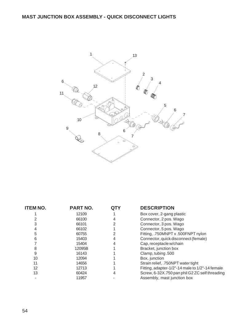
54
ITEM NO. PART NO. QTY DESCRIPTION1 12109 1 Box cover, 2-gang plastic2 66100 4 Connector, 2 pos. Wago3 66101 2 Connector, 3 pos. Wago4 66102 1 Connector, 5 pos. Wago5 60755 2 Fitting, .750MNPT x .500FNPT nylon6 15403 4 Connector, quick disconnect (female)7 15404 4 Cap, receptacle w/chain8 12095B 1 Bracket, junction box9 16143 1 Clamp, tubing .50010 12094 1 Box, junction11 14656 1 Strain relief, .750NPT water tight12 12713 1 Fitting, adapter-1/2"-14 male to 1/2"-14 female13 60424 4 Screw, 6-32X.750 pan phil G2 ZC self threading- 11957 - Assembly, mast junction box
MAST JUNCTION BOX ASSEMBLY - QUICK DISCONNECT LIGHTS
65
98
10
67
7
11
1
612
43
2
13
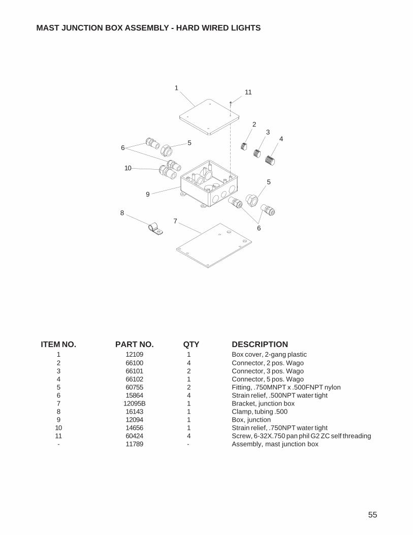
55
ITEM NO. PART NO. QTY DESCRIPTION1 12109 1 Box cover, 2-gang plastic2 66100 4 Connector, 2 pos. Wago3 66101 2 Connector, 3 pos. Wago4 66102 1 Connector, 5 pos. Wago5 60755 2 Fitting, .750MNPT x .500FNPT nylon6 15864 4 Strain relief, .500NPT water tight7 12095B 1 Bracket, junction box8 16143 1 Clamp, tubing .5009 12094 1 Box, junction10 14656 1 Strain relief, .750NPT water tight11 60424 4 Screw, 6-32X.750 pan phil G2 ZC self threading- 11789 - Assembly, mast junction box
5
87
9
6
5
10
1
6
MAST JUNCTION BOX ASSEMBLY - HARD WIRED LIGHTS
43
2
11
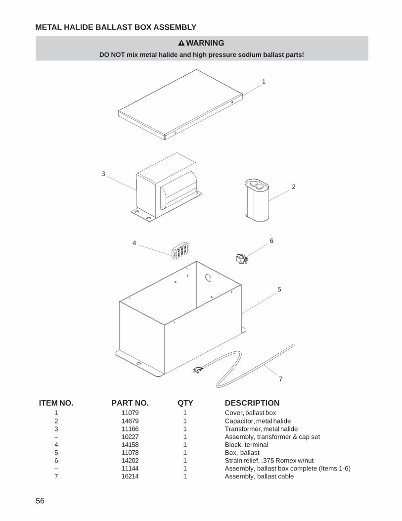
56
METAL HALIDE BALLAST BOX ASSEMBLY
ITEM NO. PART NO. QTY DESCRIPTION1 11079 1 Cover, ballast box2 14679 1 Capacitor, metal halide3 11166 1 Transformer, metal halide-- 10227 1 Assembly, transformer & cap set4 14158 1 Block, terminal5 11078 1 Box, ballast6 14202 1 Strain relief, .375 Romex w/nut-- 11144 1 Assembly, ballast box complete (Items 1-6)7 16214 1 Assembly, ballast cable
4
1
5
3
2
6
7
WARNINGDO NOT mix metal halide and high pressure sodium ballast parts!
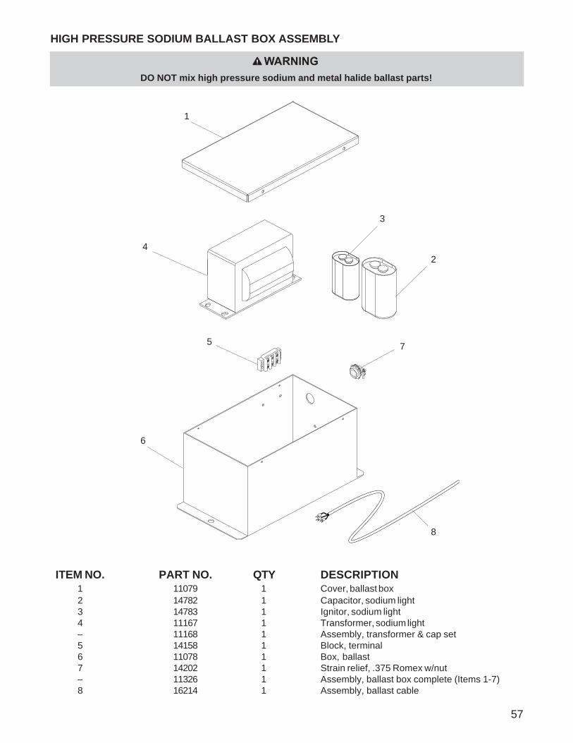
57
ITEM NO. PART NO. QTY DESCRIPTION1 11079 1 Cover, ballast box2 14782 1 Capacitor, sodium light3 14783 1 Ignitor, sodium light4 11167 1 Transformer, sodium light-- 11168 1 Assembly, transformer & cap set5 14158 1 Block, terminal6 11078 1 Box, ballast7 14202 1 Strain relief, .375 Romex w/nut-- 11326 1 Assembly, ballast box complete (Items 1-7)8 16214 1 Assembly, ballast cable
HIGH PRESSURE SODIUM BALLAST BOX ASSEMBLY
4
3
6
2
5
1
7
8
WARNINGDO NOT mix high pressure sodium and metal halide ballast parts!

AC WIRING DIAGRAM MLT 4060
58
MA
ST
PO
WE
R C
OR
D
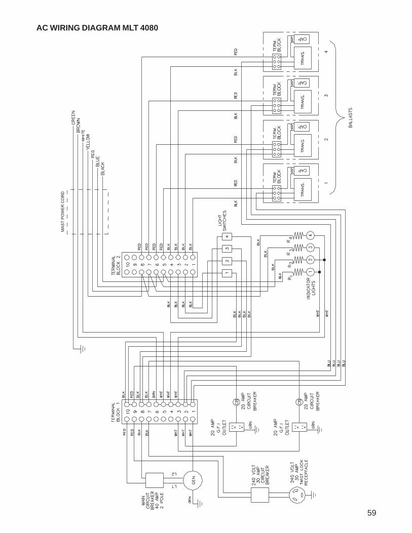
AC WIRING DIAGRAM MLT 4080
59
MA
ST
PO
WE
R C
OR
D

AC WIRING DIAGRAM - MLT 4080 WITH VOLTAGE REGULATION
MA
ST
PO
WE
R C
OR
D
WH
TW
HT
L2L1 G
EN
GR
D
F+F-
76
43
V-R
EG
60
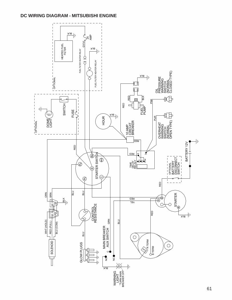
DC WIRING DIAGRAM - MITSUBISHI ENGINE
61
OP
TIO
NA
L
OP
TIO
NA
L
BAT
TER
Y DI
SCO
NNEC
TS
WIT
CH
RE
D
73
CO
M
N/C
N/O
STA
RTE
R
STA
RTE
R S
WIT
CH
DO
ME
LIG
HT
SW
ITC
H
FUS
E
BLK
HO
UR
OIL
PR
ES
SU
RE
WA
RN
ING
SW
ITC
H(N
OR
MA
LC
LOS
ED
TY
PE
)
BLK
RE
D
BLK
RE
D
FUE
LP
UM
P
PN
K
10 A
MP
CIR
CU
ITB
RE
AK
ER
TIM
E
DE
LAY
RE
LALY
RED
RED
PU
R
OV
ER
HE
ATW
AR
NIN
GS
WIT
CH
(NO
RM
AL
OP
EN
TY
PE
)
BAT
TER
Y 12
V
BLK
RE
D
REDYEL
WA
RN
ING
LIG
HT
“TU
RN
MA
INB
RE
AK
ER
OFF
”
BLK
C
NC
NO
B T
ER
MR T
ER
M
RE
D
BLU
GR
N
MA
IN B
RE
AK
ER
AU
X S
WIT
CH
GLO
W P
LUG
SB
LU
CO
NTR
OL
RE
SIS
TAN
CE
BLU
BLU
BLK
BR
N
OR
N
BLU
(CO
M)
RE
D (P
ULL
)
WH
T (H
OLD
)
SOLE
NOID
HE
ATE
D F
UE
L FI
LTE
R
BLK
GY
/VI
25
AM
P
FUE
L FI
LTE
R H
EAT
ER
RE
LAY
FUEL
FIL
TER
HEAT
ER R
ELAY
BLK
OP
TIO
NA
L
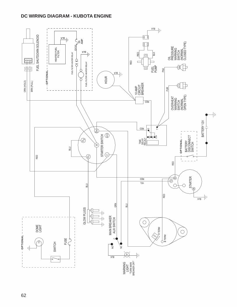
DC WIRING DIAGRAM - KUBOTA ENGINE
62
FUSE
SWIT
CH
DOME
LIG
HT
OP
TIO
NA
L
BLU
BLU
GLOW
PLU
GS
MAIN
BRE
AKER
AU
X SW
ITCH
GR
N
BLU
RED
R TE
RM
B TE
RM
NO
NC
C
BLK
WAR
NING
LIG
HT
“TUR
N MA
IN
BREA
KER
OFF”
YELRED
RED
BLK
BATT
ERY
12V
OVER
HEAT
W
ARNI
NG
SWIT
CH
(NOR
MAL
OPEN
TYP
E)
PUR
RED
RED
TIME
DE
LAY
RELA
LY
10 A
MP
CIRC
UIT
BREA
KER
PNK
FUEL
PU
MP
RED
BLK
RED
BLK
OIL
PRES
SURE
W
ARNI
NG
SWIT
CH
(NOR
MAL
CLOS
ED T
YPE)
HOUR
BLK
STAR
TER
SWIT
CH
STAR
TER
N/O
N/C
COM
3 7
BATT
ERY
DI
SCON
NECT
SW
ITCH
OP
TIO
NA
L
FUEL
SHU
TDOW
N SO
LENO
ID
ORN
(HOL
D)
BRN
(PUL
L)
RED
HE
ATE
D F
UE
L FI
LTE
R
BLK
GY
/VI
25
AM
P
FUE
L FI
LTE
R H
EAT
ER
RE
LAY
FUEL
FIL
TER
HEAT
ER R
ELAY
BLK
OP
TIO
NA
L
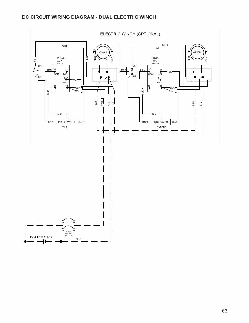
63
DC CIRCUIT WIRING DIAGRAM - DUAL ELECTRIC WINCH
BATTERY 12V
ELECTRIC WINCH (OPTIONAL)
BRN
BLKBREAKERS
50 AMPCIRCUIT
BRN
REDBRN
WHT
BRN
WHT
RE
D
RE
D
2
RE
D
1
BLK
2 1
RE
D
BLK
RED
PROX.AUXRELAY
30 87
87A
8586
PROX SWITCH
BLK
BLU
BLK
COM N/O
N/C
+ -
VIO
BLK
BLU
TILT
WINCH
EXTEND
WINCH
N/C
PROX SWITCH
BLK
BLU
BLK
86
+BLK
85
- BLU
RELAY
87AN/OCOM
30 87YEL
PROX.AUX
UP
DN
UP
DN
RE
D
RE
D
BLK
BLK
RE
D
BLK
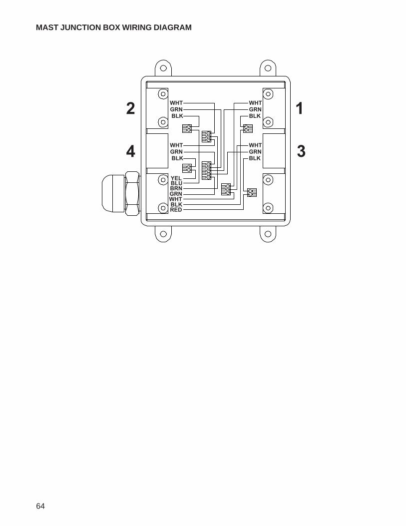
MAST JUNCTION BOX WIRING DIAGRAM
64
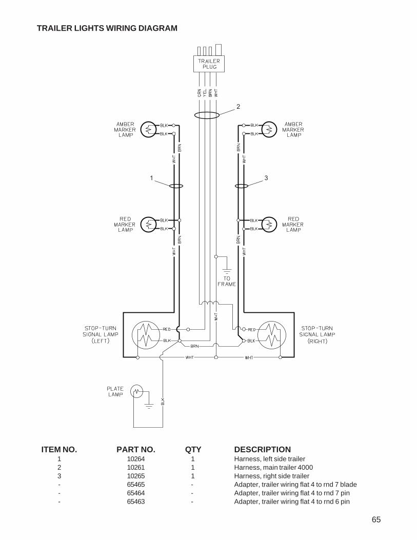
65
TRAILER LIGHTS WIRING DIAGRAM
ITEM NO. PART NO. QTY DESCRIPTION1 10264 1 Harness, left side trailer2 10261 1 Harness, main trailer 40003 10265 1 Harness, right side trailer- 65465 - Adapter, trailer wiring flat 4 to rnd 7 blade- 65464 - Adapter, trailer wiring flat 4 to rnd 7 pin- 65463 - Adapter, trailer wiring flat 4 to rnd 6 pin
1 3
2

66
NOTES:

67
SERVICE LOG
OIL GRADE AND TYPE: BRAND:
COOLANT MIXTURE: BRAND:

REV: OPART NO: 1673208.29.08
Related Documents