LHC LHC Upgrade & Crab Cavities Rama Calaga, CERN ICFA Deflecting Cavity Workshop, Jul 18, 2012 LHC Performance, few comments Upgrade & Overview Crab Scheme, Present Status, Next Steps

Welcome message from author
This document is posted to help you gain knowledge. Please leave a comment to let me know what you think about it! Share it to your friends and learn new things together.
Transcript

LHC
LHC Upgrade & Crab CavitiesRama Calaga, CERNICFA Deflecting Cavity Workshop, Jul 18, 2012
LHC Performance, few comments
Upgrade & Overview
Crab Scheme, Present Status, Next Steps

Present Performance
2011: 7TeV CM → Delivered approx 6 fb-1
2012: 8TeV CM → Delivered 7 fb-1 already in june, one track for 15 fb-1
Courtesy: LHC-OP

R. Hawkins (for ATLAS), ICHEP2012m
H = 126.5 GeV
J. Incandela (for CMS), ICHEP2012m
H = 125.3 GeV
SM Higgs Search Announcement
Both experiments with ~5 significance level
2011+2012 Data

Why Upgrade in 2023 ?1. Experiments request 3000 fb-1 by 20302. Statistical halving time very large2. Life expectancy of IR magnets (~700 fb-1)3. Detector upgrade & increase physics potential
Courtesy: L. Rossi

LINAC4(160 MeV H-)
~2014+
CERN Accelerator Chain
Booster (1.2→2 GeV)~2018
SPS Enhancements(ecloud, Impedance)
~2012-2022
HL-LHC, (IR Upgrade)(Goal: 2 x 1035 cm-2 s-1)
Upgrades
~2022
* Reduction + Crab Crossing

2
LHC Collisions
Φ=σ zσ x
ϕc
σ eff=√σ x2+σ z
2ϕc2
Piwinski angle
Upgrade: reduce * (by factor 2-4)Consequence → approx double the crossing angle (10 sep)
Ineffective Overlap
Note: don't forget hour-glass effect (~15% loss for */z)

Some Numbers
2012 mid-2014 2023
Energy 4 TeV 7 TeV 7 TeV
* [cm] 60 55 15
2 [rad] 313 247 473
R(z =7.55cm) 0.85 0.82 ~0.37
Pile-Up 20-25 ~60 140
2 ϕ≃d.√ϵ/βip(Assume: N = 2.5 m, d=10)
very inefficient
L=LHO . RΦ
A total of 1.2 km of the LHC ring to upgraded~800 MCHF (10 yrs)
IP

Pile up is serious for detectors & their design
Presently:We use leveling with sub- offsets at LHCb
Upgrade:Leveling with crossing angle (natural with crabs)Leveling with * → constant luminous region + crabs for HO

5th Workshop: LHC-CC11, Nov 20111. LHC Performance & Limitations2. Deflecting Cavity Design3. Fabrication of prototypes & Cryomodules4. SPS beam tests5. Optics & non-linear issues6. Machine protection7. Impedance & beam-beam issues8. Planning & upgrade
Full Summary Report:https://indico.cern.ch/materialDisplay.py?materialId=paper&confId=149614
Proposed in 2005 → 5 yrs of conceptual designs → Baseline upgrade scheme(5 dedicated workshops, Unkown number of papers/presentations)

Voltage = 3 MV/cavity (2-3 cavities /module)
Frequency = 400 MHz, Transverse Diameter < 300mm
Operating Temp = 2 K
Qext = 106, R/Q ~300
RF power source = 60 kW (< 18 kW nominal)
Cavity tuning/detuning ~ ± 1.5kHz (or multiples of it)
β-functions at Crab location: 3.8-4.3 km
Basic Parameters

Cavity Voltage
~6MV/ IP-side (2 cavities)
add a cavity

Pillbox Cavity
beam
Transverse Cross Section, squash
beam in/out of the plane
TM01
0
TE11
1
TM11
0
TE01
1
freq spectrum
TM01
1
TM21
0
TM11
0Y
f res∝1R
R (independent of length)
crabbing mode (HOM)
R: 400 MHz ~ 610mm 800 MHz ~ 305mm
Too big for IR regions

Lengler et al., NIM 164 (1979)Karlsruhe-CERN RF Separator
“ 1st ” SRF Deflector
Assembly into cryostat
RF separator for 10-40 GeV/c from the SPSUnknown heavy particles, baryonic states/exchange, K± & p-bar
F = 2.865 GHzVT = 2 MV/m (104 cells)
Still in use at U-70 setup at IHEP

KEK Freq: 508.9 MHzPower: 50-120 kW (Qext: 2x10⁵, BW: 2.55 kHz)
“ 1st” e± Crab Cavity
Feb 2007
LONG R&D, but short lifetime(2007-2010)
Complex HOM Damping Scheme
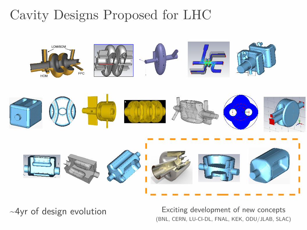
Cavity Designs Proposed for LHC
~4yr of design evolution Exciting development of new concepts(BNL, CERN, LU-CI-DL, FNAL, KEK, ODU/JLAB, SLAC)

“ Its strongly reentrant form makes the field pattern at the outer radius predominately TEM with the consequence of only moderate current flow”
E. Haebel
Freq = 100 MHzGap Voltage = 0.5 MVPbeam = 200 kW(1.6 MW @400 MHZ, NC Cavities)
/4
More History

/4 TEM Resonator
V 0
ab
~/4 gap
Z 0=V 0/ I 0
Frequency resonator lengthHOMs widely spaced
BNL: I. Ben-Zvi et al.
Pedestal to cancel Ez
Z 0 tan(β l)=1
ωC gap
290 mm 405 mm350 mm
Studied various topologies

HT
HTgap
o=0-200i=0-50
HB
HTgap
i=0-50 o=0-200
Asym Vs Sym ¼Wave
142.
5 m
m ~6mm space
122
mm
154 mm
3mm beam pipe
405 mm 337 mm
142.5 mm
Type III, Asym Type II, SymEpk 43 MV/m 32.3 MV/mBpk 61 mT 57.3 mTVacc 120 kV 0.0 V1st HOM 657 MHz 582 MHz
Prototype symmetric structure:Long. voltage is zeroBetter for non-linearity
But loss of mode separation &compactness vertically
3mm beam pipe

V0
I0
-I0
~/2
/2 TEM Resonator
Two /4 resonators → /2 Downside HOM (TE11 like) for deflection More elegant is to use two /2 resonators
Single /2 Two /2
SLAC, Z. Li ODU, J. Delayen
~/2
Z. Li, J. Delayen et al.
Now evolved into symmetric ridge waveguideFor compactness in both transverse directions
Also, Initially proposed by F. Caspers (Crab WS 2008)
ODU-SLAC

/4 = 187.5 mm
Courtesy G. Burt, B. Hall4Rod /4 Resonator
Four co-linear /4 resonators 500 MHz CEBAF Separator
Ultra compact, conical resonators for mechanical stability
Downside is the deflecting mode is not the lowest order mode
4 eigenmodes, mode 2 is our crab mode
LU-DI-JLab

Performance Chart
Double Ridge(ODU-SLAC)
4-Rod(UK)
¼ Wave(BNL)
Cavity Radius [mm] 147.5 143/118 142.5Cavity length [mm] 597 500 331Beam Pipe [mm] 84 84 84Peak E-Field [MV/m] 34 32 32Peak B-Field [mT] 61 60.5 57RT/Q [] 336 915 395Nearest Mode [MHz] 584 371-378 582
Kick Voltage: 3 MV, 400 MHzGeo
met
rical
RF
<150 mm
B1 B2
< 50 MV/m
< 80 mT
Apologies, if numbers are not latest(Pl. correct me so I can update this table)

Low
Field
High
Fiel
d
MultipactingM
ediu
m F
ield
SLAC codes to compare three cavities (Z. Li)Benchmark with measurements
4-Rod Double Ridge Quarter Wave
17 M
V/m
12 M
V/m
7 M
V/m

mTm/mn-1 MBRC 4-Rod Pbar/DRidge ¼-wave
b2 55 0 0 114
b3 7510 900 3200 1260
b4 82700 0 0 1760
b5 2.9x10⁶ -2.4x10⁶ -0.5x10⁶ -0.2x10⁶
b6 52x106 0 0 -1.7x10⁶
b7 560x106 -650x106 -14x106 0
RF Multipoles Courtesy: A. Grudiev et. al
Q ~ 10-3
~ 10-3
Like IR magnets, higher order components of the deflecting field importantLong term simulations underway to determine tolerances
Mitigation by shaping

Impedance Thresholds
Longitudinal impedance2.4 M total (7 TeV)
Strongest monopole mode:R/Q=200 → Qe<1x10³
Damping → Qe < 100-500
Transverse
Courtesy: Burov, Shaposhnikova
HOM
HOM
HOM
HOM
Crab
Strongest dipole mode:Z < 0.6 M/m (0.58 GHz)(Qext = 500)
Longitudinal

HOM probe
Input
HOM Broadband
LOM
3-5 stage ChebyshevHigh pass filter loops
HOM Damping
4 Symmetric couplers on the end caps
(2-stage high pass)
Symmetric HOM/LOM couplers on cavity body
Approx: R/Q=200 → Qe<1x10³
56 MHz RHIC Prototype
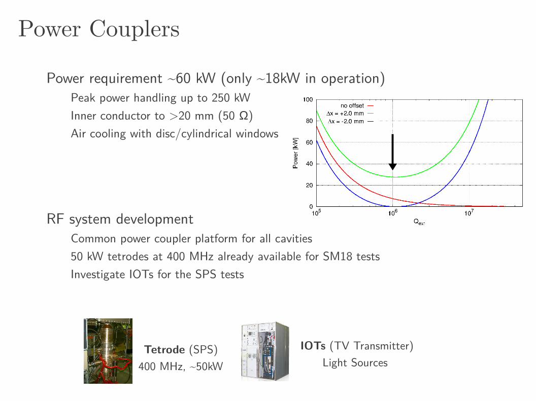
Power Couplers
Power requirement ~60 kW (only ~18kW in operation)Peak power handling up to 250 kWInner conductor to >20 mm (50 Ω)Air cooling with disc/cylindrical windows
RF system developmentCommon power coupler platform for all cavities50 kW tetrodes at 400 MHz already available for SM18 testsInvestigate IOTs for the SPS tests
IOTs (TV Transmitter)Light Sources
Tetrode (SPS)400 MHz, ~50kW

RF Noise
Δ x IP=θck RF
δϕ
ΔV TV T
≪ 1tan (θ/2)
σ x*
σ z
For example:c=570rad; V/V=0.4%x*=7m, x*=7.55cm
err=1.2rad
Amplitude jitter
Phase jitterFor example: = 0.0050, c=570radx
IP = 0.3m (5% of x
*)
LHC Main RF, = 0.0050 at 400 MHz (Philippe)(summing noise at all betatron bands from DC→300kHz)
Note: IOTs & SSAs are less noisy + betatron comb (0.001)

Cavity Tuning
Push/pull on cavity ridges
Scissor jack type mechanism
CEBAF Tuner
In operation ± 3kHzStatic: ~100 kHz
Cold stepper motors
Push/pull Blade like tuner
SM
SM
SM
SM

Overall Planning
Cavity Validation
SPSBeam Tests
Prototype Cryomodule
Final Implementation(2022-23?)
Production
LS1 LS2 LS3
Cavity Testing2012 2013 2014 2015 2016 2017 2018-23
SM18 CM Tests
Crab Cavity prototypes, SM18/SPS tests 2012 2013 2014 2015 2016
LS1
CC vertical tests in SM18
Test cryostat design
Test cryostat construction
SM18 test of proto cryomodule
SPS Beam testing
SPS Cryo 2k & upgrade (Details from Cryo)
Vacuum work at SPS (2-3 weeks needed)
SLAC Collimator installation in SPS (TbD)
RF Power installation in SPS

UK 4Rod cavityNiobium cavities finishedChemical surface treatment (now at Niowave)Heat treatment and testing at CERN (Aug 2012)
ODU-SLAC Dbl ridge cavity Niobium cavities finishedBCP & testing at Niowave & Jlab (Jul 2012)
BNL Quarter Wave CavityCall for fabrication released Cavity expected before the end of the year
Present Status
LARP +SBIR/STTR
EuCARD(+CERN)

Nb rods from solid Ingot via EDM(significant material saving)
4R Prototype Courtesy: G. Burt, Niowave
Cavity shipped to CERN (end of July) for surface treatment & testing

ODU-SLAC: Double RidgeCourtesy:J. Delayan, Niowave
Jan 2012
NiowaveSTTR, Phase I/II
May 2012

Prototype Vertical Testing, SM18
Aim: Field tests of all 3 cavities by summer 2013Characterization of surface properties
Multipacting, optical inspection, additional processingField ramping, cycling, stability and quench margin
CERN Preparations for SM18 testsBCP of the cavities, EP is needed but not easy due to geometryHigh temp vacuum baking + HPR RF Power: Recuperating 400 MHz tetrodes used for LHC-RFCryo: Existing (2-4K) + a new dedicated 2K cryostat in 2013Instrumentation: RF, second sound, T-mapping & optical LLRF & services: Mostly exist from present testing

ISO4ISO5
ISO4/5
HPR
UPW
ISO5OIHIE-ISOLDEISO5
Optical Telescope
CERN SM18 Facility & Upgrade
T-Mapping + 2nd SoundTest Stand
Courtesy: J. Chambrillon, K-M. Schirm
3D bead-pull

Cryomodule Development
Initiating a joint effort with US and European partners
Next StepsInitial concepts in 6-8 months (FNAL, SBIR, Triumph, CEA-CNRS)Immediate task to identify constraints (environmental & RF)Engineering meeting at the end of 2012 for conceptual review
Some initial work done for elliptical cavitiesFNAL (Y. Yakovlev et. al), 2010 ODU-Niowave: SBIR, Phase I
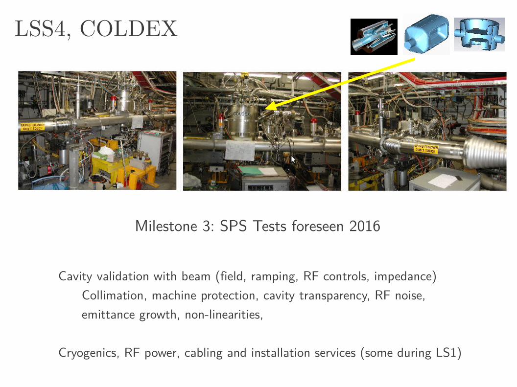
LSS4, COLDEX
Cavity validation with beam (field, ramping, RF controls, impedance)Collimation, machine protection, cavity transparency, RF noise, emittance growth, non-linearities,
Cryogenics, RF power, cabling and installation services (some during LS1)
Milestone 3: SPS Tests foreseen 2016

Next Steps
Cavities, end of 2012Two prototypes at hand and 3rd to come soonCavity testing is the immediate focus → 1st milestone (end of year)
Cryomodule, end of 2014 Establishing joint collaborations with N.A. (FNAL, Triumph) & Euorpe (CEA-CNRS/IN2P3), more welcomeNext step to review conceptual designs
SPS/LHC Tests, end of 2016-17Preparation (cabling, RF, cryo etc..) in SPS will start 2013

H. Padamsee et al., PAC95Example: Cavity Quench
Transient cavity Q meas. from high power RF pulses → thermal breakdownNominally performed during cavity processing (Tstart 2K)Determine the “ Hc
RF ” limit for 2K
LARP contribution to either quench studies and/or machine protection, highly desired
~150 s (2 turns)
Operating field
Breakdown field lower close Tc
~50 s (1/2 turn)

5 db
m/d
iv
500 kHz
500 kHz
RF Noise, LHC with 1-T feedbackP. Baudrenghien
Selective reduction at all frev lines (V=1.5MV, QL=60k)
Using a betatron comb, we can expect ~16dB reduction at selective frequencies

4 LHC Cavities in SPS
RF Power
SPS, BA4 Setup (1998)
Y-Chamber like, similar to present COLDEX
Courtesy E. Montesinos
50 kW Tetrode
Cryo-Line
Crab cavity test setup in SPS will look similar
Related Documents