S. S. PAPADOPULOS & ASSOCIATES. INC. CONSULTING GROUND-WATER HYDROLOGISTS Site: >M:^M^C&^ Break: .««^«a__£hi£^ Other: S. S. PAPADOPULOS S. P. LARSON C. B. ANDREWS December 23, 1991 Ms. Susan Hoff Regional Project Manager U.S. Environmental Protection Agency Region VU 726 Minnesota Avenue Kansas City, MO 66101 Re: Final Quality Assurance/Sampling and Analysis Plan ^^flW 0.^ 1931 Dear Ms. Hoff: Attached you wUl find sbc copies of tlie final C^ality Assurance/Sampling and Analysis Plan (QA/SAP), pursuant to Paragraph 38, Section Vm ofthe Administrative Order on Consent, U.S. EPA Docket No. Vn-92-F-O, dated November 19,1991. This final QA/SAP has been modified to reflect the comments contained in your letter to Mr. Steven P. Larson, received in this office December 20, 1991, which stated that the U.S. EPA "...approves with comment the November 1991 Draft Quality Assurance/Sampling and Analysis Plan (QA/'SAP) for die Ground Water Operable Unir at the FAR- \L\R-CO subsite, Hastings Ground Water Contamination site." Your comments also were discussed by us over the telephone on December 20, 1991. Bids are being solicited from drilling companies at this time. As soon as the bids have been returned by the companies and a drilling contractor has been selected, personnel qualifications for the selected drilling company will be submitted to the EPA for review and approval. If you have questions or wish additional information, please call me or Steve Larson at 301/468-5760. Very truly yours, S.S. PAPADOPULOS & ASSOCIATES, INC. \n^\ 189351 Claudia Stone Senior Hydrogeologist cc: William T. Session 1 2 2 5 0 ROCKVILLE PIKE, SUITE 2 9 0 , ROCKVILLE, MARYLAND 2 0 8 5 2 ( 3 0 1 ) 4 6 8 - 5 7 6 0 FAX ( 3 0 1 ) 8 8 1 - 0 8 3 2

Welcome message from author
This document is posted to help you gain knowledge. Please leave a comment to let me know what you think about it! Share it to your friends and learn new things together.
Transcript

S. S. PAPADOPULOS & ASSOCIATES. INC. C O N S U L T I N G G R O U N D - W A T E R H Y D R O L O G I S T S
Site: >M:^M^C&^
Break: .««^«a__£hi£^ Other:
S. S. PAPADOPULOS S. P. LARSON C. B. ANDREWS
December 23, 1991
Ms. Susan Hoff Regional Project Manager U.S. Environmental Protection Agency Region VU 726 Minnesota Avenue Kansas City, MO 66101
Re: Final Quality Assurance/Sampling and Analysis Plan
^ flW 0.^ 1931
Dear Ms. Hoff:
Attached you wUl find sbc copies of tlie final C^ality Assurance/Sampling and Analysis Plan (QA/SAP), pursuant to Paragraph 38, Section Vm ofthe Administrative Order on Consent, U.S. EPA Docket No. Vn-92-F-O, dated November 19,1991. This final QA/SAP has been modified to reflect the comments contained in your letter to Mr. Steven P. Larson, received in this office December 20, 1991, which stated that the U.S. EPA "...approves with comment the November 1991 Draft Quality Assurance/Sampling and Analysis Plan (QA/'SAP) for die Ground Water Operable Unir at the FAR-\L\R-CO subsite, Hastings Ground Water Contamination site." Your comments also were discussed by us over the telephone on December 20, 1991.
Bids are being solicited from drilling companies at this time. As soon as the bids have been returned by the companies and a drilling contractor has been selected, personnel qualifications for the selected drilling company will be submitted to the EPA for review and approval.
If you have questions or wish additional information, please call me or Steve Larson at 301/468-5760.
Very truly yours,
S.S. PAPADOPULOS & ASSOCIATES, INC.
\ n ^ \
189351
Claudia Stone Senior Hydrogeologist
cc: William T. Session
1 2250 ROCKVILLE PIKE, SUITE 290, ROCKVILLE, MARYLAND 20852 ( 3 0 1 ) 4 6 8 - 5 7 6 0 FAX (301 )881 -0832

FINAL QUALITY ASSURANCE/SAMPLING AND ANALYSIS PLAN FOR THE GROUND WATER
OPERABLE UNIT AT THE FAR-MAR-CO SUBSITE HASTINGS GROUND WATER CONTAMINATION SITE
HASTINGS, NEBRASKA
DECEMBER, 1991
Prepared for: Morrison Enterprises
Prepared by: S. S. PAPADOPULOS & ASSOCIATES, INC.
12250 Rockville Pike, Suite 290 Rockville, Maryland 20852
(301) 468-5760

TABLE OF CONTENTS
Page
LIST OF TABLES iv
LIST OF FIGURES iv
REPORT
1.0 INTRODUCTION 1
2.0 DATA QUALITY OBJECTIVES 3
2.1 Ground Water Chemistry 4 2.2 Soil Sample Chemistry 4 2.3 Well-Head Survey and Water-Level Measurements 5 2.4 Aquifer Characteristics 5
3.0 WELL DRILLING/INSTALLATION 6
3.1 Drilling Procedures 6 3.2 Lithologic Logging 7 3.3 Monitoring Well Installation 8
3.3.1 Selection and Installation of Well Casing and Screen 9 3.3.2 Placement of Annular Sealants 10
3.4 Well Development 11
4.0 SOIL SAMPLING 12
4.1 Instrument and Detection Limits 13
4.2 Sampling and Analytical Procedures 14
5.0 GROUND-WATER SAMPLING 17
6.0 WATER- AND LIQUID-LEVEL MEASUREMENTS 18
7.0 ESTIMATING AQUIFER CHARACTERISTICS 20
8.0 WELL-COMPLETION DOCUMENTATION 21

TABLE OF CONTENTS Continued
Page
9.0 FIELD-ACTIVITY DOCUMENTATION 22
9.1 Water-Level Measurements 22 9.2 Ground-Water Sampling 23 9.3 Instrument Calibration 24
10.0 DECONTAMINATION 25
10.1 Equipment Decontamination 25
10.2 Personnel Decontamination 26
11.0 LABORATORY-TESTING PROCEDURES 27
11.1 Ground-Water Samples from Wells 27
11.2 Soil Samples 27
12.0 QUALITY-CONTROL SAMPLING 28
12.1 Field DupUcates 28 12.2 Equipment Rinsate Blanks 28
12.3 Volatile Organic Trip Blanks 29
13.0 AUDITS OF PROJECT ACTIVITIES 30
14.0 PREVENTIVE MAINTENANCE AND CORRECTIVE ACTION 32 14.1 Preventive Maintenance 32 14.2 Corrective Action 32
15.0 DATA HANDLDsfG AND ASSESSMENT OF PRECISION, ACCURACY AND COMPLETENESS 33 15.1 Precision 33 15.2 Accuracy 34 15.3 Completeness 34
16.0 REFERENCES 35
u

TABLE OF CONTENTS Continued
ATTACHMENT A Drilling Specifications
ATTACHMENT B Documentation Forms
ATTACHMENT C Ground Water Sampling Plan
ATTACHMENT D State of Nebraska, Ruling of Substantial Equivalence on WeU-Completion Methods
m

LIST OF TABLES
Table 2-1 Data Quality Objectives for Soil and Ground-Water Samples
Table 2-2 WeUs for WeU-Head Survey and Water-Level Measurements
Table 3-1 Monitoring WeU Locations, Construction Details, and Rationale
Table 9-1 Field Equipment Maintenance Schedule
LIST OF FIGURES
Figure 1-1 City of Hastings
Figure 3-1 Proposed Monitoring WeU Locations
Figure 3-2 . Monitoring WeU Construction DetaUs
IV

1.0 INTRODUCTION
This QuaUty Assurance/Sampling and Analysis Plan (QA/SAP) provides procedures for field
activities to he performed at the FAR-MAR-CO subsite of the city of Hastings ground water
contamination site (Figure 1-1). These procedures are presented in sufficient detail such that data
coUection activities can be tracked and the quaUty of these activities can be assured. This QA/SAP
is written using guidelines issued by the U.S. Environmental Protection Agency, Interim Guidelines
and Specifications for Preparing QuaUty Assurance Project Plans, QAMS-005/80 (February 1983),
and incorporates by reference appUcable portions of other subsite documents, such as the Final Work
Plan for a Ground Water Remedial Investigation/FeasibiUty Study at the FAR-MAR-CO Subsite
(Morrison Enterprises, August 1991). Therefore, discussions of site background and project
organization incorporated in the Work Plan are not reiterated herein.
DriUing specifications for this investigation are contained in Attachment A; various forms that
may h& used to document activities for the FAR-MAR-CO subsite are contained in Attachment B;
groimd-water sampling, handling, and tracking procedures are contained in Attachment C.
Attachment C is the Ground-Water Sampling Plan developed for Morrison Enterprises (ME) for
ground-water sampling at the FAR-MAR-CO subsite.
Revisions to this plan may be required as new or unique field activities are initiated or
procedures are changed. Revisions to this QA/SAP wUl be reviewed and approved by the EPA
Remedial Project Manager (RPM) prior to implementation. Other EPA program or project-level
personnel may review this plan and its revisions at the discretion and direction of the RPM.
The work to be completed is in support of the Remedial Investigation/FeasibUity Study for
the FAR-MAR-CO subsite. SpecificaUy, the work includes:
• Installing seven monitoring weUs
• Preparing Uthologic logs of boreholes

CoUecting undisturbed soU samples
Measming head space for soU samples coUected below the water table
Slug testing selected weUs
Surveying weU-heads for location and elevation
Measuring of water levels
CoUecting ground water samples from the newly instaUed weUs
Estimating transmissivity of the aquifer either through review of municipal-weU specific-capacity data and/or slug testing selected weUs
Video logging or otherwise documenting weU completion detaUs of one irrigation (I-49) and one domestic well (D-8)

2.0 DATA QUALITY OBJECTIVES
Data quaUty objectives (DQO) are quaUtative and quantitative statements that specify the
quality of the data required to support agency decisions during remedial response activities. Table
2-1 summarizes the chemical data to be coUected for the FAR-MAR-CO subsite. AU chemical data
collected at the site wUl be coUected, analyzed, validated, and tracked using CLP or equivalent
analytical procedures that provide data of suitable quaUty to satisfy the requirements of the EPA. ME
wUl ensure that the selected laboratory participates in the CPL or an equivalent program and has an
EPA approved QuaUty Assurance Plan in place. DQO Level HI wUl be used, but DQO Level FV
documentation wiU be retained by the laboratory on disk for at least 10 years.
Attainment of precision, accuracy and completeness goals ensures that aU measurements are
representative of the media being sampled and the conditions being measured. Definitions of these
parameters that apply to the project are summarized below:
• Precision A measurement of die degree of agreement of data that is quantitatively assessed based on the standard deviation.
c • Accuracy The agreement of a measurement with an accepted reference or true value.
• Completeness The amount of vaUd data obtained from a prescrit)ed measurement system throughout the project as compared with that expected and required to meet the project goals.
The above parameters are discussed in Section 15.0.
Representative field and laboratory data wUl be assured through the use of consistent methods
of data coUection, which involve well installation, sampling procedures, and sample preservation;
these methods are discussed in subsequent sections and in Appendix C. ComparabUity of data
throughout the scope of the project wUl be assured by foUowing established protocols for sample
coUection and analysis and by recording field and laboratory data in consistent units.

2.1 Ground Water Chemistry
New monitoring weUs wiU be instaUed at the FAR-MAR-CO subsite to provide additional
sampling locations for estimating the areal extent and concentration of the organic plume known to
be present at the site. These data also wUl be used to estimate the volume and areal extent of
contaminated ground water requiring treatment. Criteria for placement of these weUs have been
detaUed in Section 5.2 and Table 5-2 of the Work Plan.
The newly installed monitoring weUs wiU be sampled once at the completion of weU
instaUation/development and again at a time that coordinates with the EPA's quarterly sampling at
FAR-MAR-CO and other Hastings subsites. This sampling wiU not take place in the faU. AU
ground-water samples wiU be analyzed for volatUe organic compounds (VOCs) and ethylene
dibromide (EDB) in order to refine the nature and horizontal and vertical extent of contamination
associated with the FAR-MAR-CO subsite. Samples for the analysis of routine water-quality
parameters (major anions, cations, dissolved siUca, total dissolved soUds, alkalinity) wiU be collected
from selected new monitoring weUs to provide information for site characterization and screening of
remedial altematives. Ground-water sampling is discussed in Section 5.0 and Attachment C;
analytical procedures are discussed in Section 11.0.
2.2 Soil Sample Chemistry
SoU samples wiU be coUected from boreholes from selected depths below the water table to
determine total organic carbon (TOC) in soils. AdditionaUy, as described in more detail in Section
4.0, selected soU samples wiU be placed in glass containers witii teflon-lined caps, and headspace
samples from these containers wUl be analyzed in the field using a portable Gas Chromatograph (GC).

2.3 Well-Head Survey and Water-Level Measurements
A comprehensive well-head survey wiU be conducted of selected existing and newly installed
monitoring wells and pertinent industrial, domestic, and irrigation weUs. The weUs to be surveyed
are listed in Table 2-2. The accuracy and precision of the survey data must meet requirements
outiined in the siuA ey subcontract. The survey wUl provide accurate datum elevations for
construction of piezometric surface maps. The ground-water flow direction and hydrauUc gradient
wiU be determined on the basis of water-level measurements from these measurement points.
Water levels wiU be measured after well development, prior to initial sampling, and then
monthly. The wells to be measured for this investigation are Usted in Table 2-2. The procedures to
be used for water-level measurements are described in Section 6.0 and Attachment C.
2.4 Aquifer Characteristics
The transmissivity of the aquifer wUl be estimated from slug testing selected weUs and from
a review of the municipal-well specific-capacity data. Specific capacity is the pumping rate of the
weU divided by the drawdown, usually reported as gaUons per minute per foot of drawdown. These
data generaUy include the pumping rate, drawdown, and length of the test. The procedures for
estimating aquifer characteristics are,discussed in Section 7.0.
3.0 WELL DRILLING/INSTALLATION
The minimum guidelines that ME wiU foUow in instaUing weUs and logging boreholes at the
FAR-MAR-CO subsite are described below. The driUing specifications for this project are included
as Attachment A to this QA/SAP. ME wiU be responsible for selecting the driUer, ensuring the drUler
adheres to the drUling specifications, and ensuring that changes made in the field are consistent with
the original specifications or are cleared with the RPM prior to execution.
The estimated locations, construction detaUs, and rationale for the proposed monitoring weUs
are summarized on Figures 3-1 and 3-2 and in Table 3-1. The new monitoring weUs wUl be sited
to better define the extent of affected ground water in areas downgradient from the FAR-MAR-CO
subsite. A well wUI also be instaUed north of weU MW-14 to provide information on groimd-water
conditions in that area. The new wells downgradient of die site wiU be instaUed in a step-wise
fashion along the apparent axis of ground-water migration from the source area. The drilling wiU
begin at the proposed site closest to the subsite and proceed to the east. The final locations for weUs
to the north and south of the axis of migration, as weU as the final location of the deep weU along
the axis of migration wUl be based on the contaminant levels found in the headspace from soU
samples measured in the field. Those soU samples wUl be coUected from the step-wise soU borings.
The contaminant-level criteria for locating the borings is detaUed in Section 5.2 of the Work Plan.
The remaining subsections of Section 3.0 present the procedures for driUing and logging of
the boreholes and weU instaUation and development. Section 4.0 describes coUection of soU samples,
and Section 5.0 discusses coUection of groimd-water samples.
3.1 Drilling Procedures
Boreholes for the monitoring weUs wtU be driUed using the hoUow stem auger, dual waU
hammer, reverse rotary or cable tool driUing method. The selected drilling method wUl be based on
the reconimendations of the driller and compatibUity of the driUing method with sample-coUection

techniques. If the geologic conditions encountered at the subsite are different from those expected,
the drilling methods may be changed for subsequent boreholes.
It is anticipated that the boreholes wUl be driUed by hoUow-stem continuous-flight auger with
minimal addition of water. Inside diameter of the hoUow-stem auger (necessary to instaU 2-inch
tubing) shaU be approximately 6 inches, and the outside diameter shaU be approximately 10 inches.
The CME-75 and Acker-Soil-Max auger drUl rigs have 11,(XK) ft-lbs of torque, which is sufficient
to achieve the anticipated (iriUing depths.
A spUt-spoon sampler wUl be driven ahead of the driU bit during driUing to coUect
undisturbed soil samples from below the water table. SoU samples wiU be used for Uthologic logging,
and chemical analysis. Soil sampling is further discussed in Sections 4.0.
The area under the back of the drUling rig and the area surrounding the borehole wUl be
covered in plastic sheeting prior to initiation of drilling; This covering wUl safeguard against
contaminating the groimd with cuttings, driUing fluids, or hydrauUc oUs and make cleanup of the
drUling site easier. All weU drilling equipment wUl be inspected for damage and steam cleaned prior
to and between use at aU weU-instaUation sites. -
3.2 Lithologic Logging
The on-site geologist wiU be responsible for directing drilUng operations, coUecting,
describing, and labeling aU driU cuttings and spUt-spoon samples, and compUing the Uthologic log
of each boring. AdditionaUy, the geologist wiU document aU drilling, sampling, decontamination, and
borehole grouting activities in a field log.
The logging wiU be accomplished by monitoring the driU cuttings above the water table
during driUing to note lithologic changes, describing the spUt-spoon samples that wiU be collected at
five-foot intervals below the water table, and monitoring the drilling rig performance and penetration
rates. A general Uthologic log using the Unified SoU Classification System (USCS) system wUl be
generated for each borehole based on the above data. InitiaUy the geologist wUl describe the basic

lithology ofthe driU cuttings or split-spoon sample using the USCS system. The foUowing Uthologic
information wUl be recorded on the logging form:
USCS group symbol (GW, SW, ML, etc.)
SoU type
Color
Grain size
Sorting (weU-graded, poorly-graded)
Obvious odor
OVA readings
Blow courts
Moisture content
Sample type (cuttings, spUt-spoon)
The geologist wUl work closely with the driUer to identify changes in the rate of drilling
penetration and to estimate the lag time required for cuttings to be brought to the surface.
Information regarding the weU location, driUing method, penetration rate, blow count, etc. also wiU
be recorded on the logging form, as shown in Attachment B.
3.3 Monitoring WeU Installation
Once the desired depth ofthe borehole is reached, aU cuttings and slough wUl be cleaned from
the borehole. For weUs to be placed at the base of the aquifer, driUing wUl continue untU the on-site
geologist confirms the aUuvium/bedrock contact through visual logging of the cuttings and/or changes
in the rate of drilling penetration, along with information on the area geology. In cases where the
borehole has penetrated the bedrock by less than five feet, the borehole wUl be backfiUed to the
aUuvium/bedrock contact using filter pack material and the weU completed. In cases where the
8

borehole penetrated the bedrock by more than five feet, or the borehole appears to have encountered
highly permeable lens within the bedrock, the borehole wUl be backfUled with cement/bentonite slurry
or Volclay grout to just above the aUuvium/bedrock contact. Once the bentonite or Volclay has
cured, several feet of fUter pack wiU be placed atop the grout and the remainder of the weU
completed.
The instaUation of all monitoring weUs wUl begin immediately after borehole completion. If
the completed borehole must be left open over night, it wiU be cleaned out prior to weU instaUation.
Once instaUation commences, at a minimum the casing/screen material, natural filter pack, and
bentonite seal wUl be instaUed before any break in the instaUation activities occurs. A schematic
weU-construction diagram is shown on Figure 3-2.
3.3.1 Selection and Installation of Well Casing and Screen
AU weU-construction materials wUl be steam cleaned and inspected for damage prior to
instaUation. The diameter and lengths of individual casing and screen sections wiU be verified by
measurement. The weU casing and screen then wUl be assembled and instaUed in the weU. Flush-
threaded Schedule 40 PVC casing and continuous slot Schedule 40 PVC screen wiU be used. The
screen slot size wUl be 0.01 inch. The screen slot size was based on reviewing the results of prior
grain size analyses and previous weU-completion practices for monitoring weUs at the FAR-MAR-CO
subsite, and has been approved by the EPA. Screens wUl be 10 feet long. CentraUzers wiU be placed
at the top and bottom of the screen, and every 40 feet along the casing.
Stringers of sUty clayey sand and clayey sUt have been identified in the area underlying the
FAR-MAR-CO subsite and vicinity and have been inferred to represent aquicludes or aquitards.
South of the subsite at the Hastings East Industrial Park similar stringers have been recognized.
These clayey interbeds wiU be identified by logging drill cuttings and are not anticipated to be
problematical during the present investigation. Monitoring weUs wiU not be screened across such
layers, but wUl be placed above or below them at the interval that most closely approximates the
EPA-approved weU depth.
After the screen and casing have been placed in the borehole, the well wiU be completed by
natural development. The annulus around the well screen and casing wUl be naturaUy developed by
aUowing the formation material to coUapse around the screen and casing. This method was
determined by the state of Nebraska, Department of Health, to be substantiaUy equivalent to Nebraska
regulations governing the completion of monitoring wells. The determination by the state is contained
in a letter dated July 31, 1991, a copy of which is reproduced in Attachment D.
The natural-development method consists of carefully pulling back the augers to expose the
screen and encouraging the formation material to coUapse and settle around the screen by pumping
or surging the weU. Once the formation material has settled to a level of about 3 feet above the
screen, a 3- to 4-foot-thick seal of bentonite peUets or chips wUl be emplaced by tremie. The
remaining annulus surrounding the blank casing also wUl be backfiUed by natural development in the
manner just described. It may be necessary to add water and clean fUter pack material to ensure
complete backfilling of the annular space. City of Hastings water wiU be used in that event, and
volumes of water used wiU be recorded in the field log book. AU formation and seal heights wiU be
measured by a weighted tape to ensure their level as the well is completed.
3.3.2 Placement of Surface Annular Sealants
The top 10 feet of the armulus around the casing wiU be sealed using either a cement-
bentonite grout consisting of 3 percent bentonite and 7 to 8 gallons of water per 94-pound sack of
cement or 23 gaUons of water for each 50-pound sack of Volclay grout. The grout wiU be placed
by tremie tube, if necessary. The decision to complete each weU above grade widi a stick up or
below grade with a flush-mounted vault box wUl be based upon surface conditions encountered at
each drill site.
10

AU monitoring weUs wUl have a concrete surface seal that wUl completely cover all conductor
casings. The concrete pad wUl be 5 inches thick, and it wiU be sloped to divert water away from the
weU casing. AdditionaUy, the inner casing wUl be enclosed by 6-inch diameter protective steel casing
with a locking cap. Each weU wiU be protected by four posts placed in the concrete pad. The weU
identification number wUl be marked permanently on the inside and outside of the protective casing
and wiU be written in the concrete pad. A steel pin wUl be placed in the concrete pad at a location
suitable for representing ground surface elevation.
A record of the completion activities of each weU wUl be kept in the field log and on a weU
completion diagram. An example well-completion diagram is shown in Attachment B. This record
wUl include the volume of water introduced to the borehole during completion activities. WeU
locations, top-of-casing (inner and outer) elevations, and ground-surface elevations wUl be surveyed
by a licensed surveyor after all of the weUs have been completed.
3.4 Well Development
Once the well has been constructed it wUl be developed to remove fluids introduced during
drilling, if any, and to remove any fine materials that may be blocking the aquifer. The wells wiU
be developed by bailing, surging, and/or overpumping, or an appropriate combination of these
methods until the produced water is relatively free of fines. Use of formation water for weU
development is anticipated, due to the high permeabUity of die formations in the Hastings area. If
weUs are completed in low-yielding zones, clean water of known chemical quaUty wiU be used to
facUitate weU development. Water wUl most likely be obtained from the Hastings city water supply.
The quantity of water added to the weU wiU be recorded and every attempt wiU be made to remove
aU water added during weU completion. If water is added to the weU during drilling, weU
development wUl continue until indicator parameters ^pH, electrical conductivity, and temperature)
have StabUized.
11

4.0 SOIL SAMPLING
Undisturbed soU samples wUl be collected from boreholes using a spUt spoon to aUow detaUed
classification of material types and to obtain soU samples for total organic carbon analysis. These
samples wiU be coUected at 5-foot intervals below the water table, using an 18-inch or 24-inch long
sampler. Section 11.0 discusses laboratory testing procedures for soil samples.
Once the water table has been reached, the borehole wiU be cleaned of aU cuttings. SpUt-
spoon samples wiU be coUected in a 2-inch diameter sampler driven into the undisturbed sediment
with a 140-pound hammer falling freely through a 30-inch drop (in accordance with ASTM D1586).
The number of blows necessary to drive each 6-inch increment of the sampler wUl be recorded by
both the drUler and the on-site geologist. This information wiU be used to help identify the sediment
type and compile the Uthologic log. Samples wiU be logged, preserved and labeUed as follows.
Material from the spUt spoon wUl be scanned as quickly as possible upon retrieval for the
presence of organic vapors by moving a flame or photo ionization detector (FID or PID) along the
opened spoon. Special care wiU be taken to minimize opportunities for volatile organic compounds
to escape from the sample by volatUization. Immediately after organic-vapor scanning, a portion of
the material from each spoon wiU be placed into two sealed glass containers with a sepmm (such as
a 40-ml vial). One container wiU be retained for back-up purposes. One container of each sample
wiU be heated for a short time and an aliquot of the headspace in the container wUl be removed using
a gas tight syringe and analyzed using a portable GC. The material to be analyzed by this method
wiU be selected from areas along the spoon having the greatest moisture content and/or the maximum
spikes on the FID/PID. The soU samples wiU be analyzed by the GC for carbon tetraciUoride and
ethylene dibromide.
12

4.1 Instrument and Detection Limits
The instrument considered to carry out the field analyses is a Photovac lOS, portable GC
equipped with a phonoionization (PID) detector and a 10.6 eV excitation lamp. The apparatus is
equipped with an isothermal oven permitting analyses to be performed at constant temperature (10
to 40 degrees C). The chromatographic separation takes place in wide-bore capUlary columns (.053
mm I.D., usuaUy 30 feet long). The detection limits reported by the manufacturer for the chemicals
of concem for the vapor phase, and those calculated for the corresponding aqueous phase at
equiUbrium, are given below:
EDB: 10 to 50 ppb (wt/wt) in the vapor phase, corresponding to approximately 0.3 to 1.5
ppb (wt/wt) in the aqueous phase at equUibrium (dimensionless KH = 0.045)
CCI4: 200 to 300 ppb (wt/wt) in the vapor phase, corresponding to approximately 0.2 to 1.1
ppb (wt/wt) in the aqueous phase at equUibrium (dimensionless KH = 1.09)
The detection Umit of the instmment can be improved for CCI4 by using an optional 11.7 eV
excitation lamp (instead ofthe 10.6 eV). However, the 11.7 eV excitation lamp is reported to be less
reliable than the standard 10.6 eV lamp (fluctuation of excitation power, short Ufe duration). The
standard 10.6 eV excitation lamp wUl be used for this survey. The achievable detection Umit for both
EDB and CCI4 is approximately 1 ppb in water (the analyses are actuaUy performed on the gas phase
in equiUbrium with water), which should aUow the characterization of a contaminated ground-water
plume weU into the low ppb range.
An additional gain in detection Umit (5 to 10 times for the compounds of concem) can be
achieved, if necessary, by adding methanol to the samples in their sealed containers. Methanol has
the effect of promoting the partitioning of the volatUe organic compounds of concem to the vapor
phase, thereby increasing their concentration in the vapor phase relative to the water and soU matrix.
For the field work at Hastings, we do not anticipate the use of the methanol-addition method because
of the relatively low detection Umits achievable for the compounds of concem with the proposed
13

analytical procedure (GC/PID). If the methanol-addition method is used the procedure wiU be
documented in the laboratory field book.
4.2 Sampling and Analytical Procedures
The GC wiU be calibrated in the field by injection of the vapor of standards containing a
known concentration of the chemicals of concems. Fresh standards wiU be prepared once a week by
dUution of known amounts of EDB and CCI4 in water. Vials sealed with teflon-coated mbber septa,
identical to the vials to be used for the collection of samples in the field, wUl be used to prepare and
store the standards. The vials wUl be stored up-side down to minimize losses with time, and kept
cold when not in use. In addition, caUbration gas standards (e.g. Scott's Specialty Gases grade)
containing benzene and xylenes wUl be used to caUbrate the relative retention times and response
factors of the apparams in the field.
Selected standards (including blanks) wUl be injected prior to and after analysis of groups of
two to four samples to determine the shift in response of the apparatus. If any significant shift (e.g.
more than 25 percent variation on selected caUbration peaks) is observed between the injection of two
series of selected standards, a dupUcate selected standard injection wUl be performed for confirmation.
A conformed shift in response wiU be used for correcting the results of the samples analyzed between
the injections of the two sets of selected standards. The shift in response wUl be assumed to be linear
with time and the corrections wiU be applied on the basis of the time of injection of each individual
sample.
A complete caUbration of the apparatus wUl take place at least twice daily. The
chromatographic base line wiU be detemiined by monitoring the carrier gas (ultra zero air). The
equipment blank wUl consist of injecting ultra pure nitrogen gas, which wiU be first introduced in a
sealed sampUng vial (equipment blank vial); it wiU be handled simUarly to the standards and samples
for analysis. Ambient air wiU be injected at least four times daily to characterize atmospheric
background. Gas-tight syringes (HamUton) wUl be used to transfer and inject vapor standards and
14

samples; the injection volumes are expected to be between 100 and 1,000 microliters. In addition to
the injection of variable volumes, extra nitrogen (e.g. Scott's Specialty Gases) wiU be avaUable for
dilution, if required.
Samples wUl be taken as soon as avaUable (from the spUt-spoon), and introduced into glass
containers. The glass containers wUl be sealed immediately with teflon-coated septa to prevent
volatUization ofthe compounds ofconcem. The volume ofthe glass containers wUl be approximately
250 ml. The samples wiU be allowed to equiUbrate at room temperature, after which vapor samples
wUl be taken through the septum with a gas-tight syringe for analysis. Duplicate and triplicate
analyses wUl be performed for approximately 10 percent of the samples analyzed. For the first few
samples, several vapor samples taken at different times during the equiUbration period wiU be
analyzed to determine the time required to achieve equiUbrium in the sampling jars. Ambient air
temperature in the locale were the samples wUl be stored to equUibrate wUl be monitored on a regular
basis and reported in the field book.
The field geochemist wUl be trained to perform repairs on the field GC (gas leaks,
programming, and minor repairs), and as a precaution arrangements wiU be made ahead of time to
insure avaUabiUty of a spare field GC from the manufacturer. Should the apparatus become non-
repairable in the field, a replacement wUl be ordered from the manufacturer for next-day delivery.
In that evenmality all unanalyzed samples wUl be stored together with standards in a cool location
for next-day analysis.
SoU samples for total organic carbon analysis wiU be taken from the area of the split spoon
having the highest moisture content and/or the highest spike on the FID/PID. The samples wUl be
coUected directiy from the opened spoon into wide-mouth glass jars with teflon-lined caps and stored
in a chUled cooler for transport to the laboratory. The selection of which of the samples are to be
analyzed wUl be made in the field and wUl be based on a combination of the weU location and the
results of the field testing.
15
Material from the shoe at the bottom-most end of the sampler (deepest part driven) wiU be
extracted and used for Uthologic description. The percent recovery (length of core recovered divided
by length pressed) wiU be recorded for each sample. The sampler wUl be decontaminated between
samples by washing with nonphosphate detergent and triple rinsing in organic-free DI water or by
steam cleaning.
AU samples wUl be marked with the project number, borehole number, sample number, depth
interval, and time and date of sample coUection and sampler's initials using a black indelible marker.
This information also wiU be recorded in the field log book (see Attachment C for procedures).
16

5.0 GROUND-WATER SAMPLING
Ground-water samples wiU be coUected from the newly installed monitoring weUs twice
during this investigation. The wells first wiU be sampled foUowing instaUation/development, and
again at a time that coordinates with the EPA's quarterly sampling at FAR-MAR-CO and other
Hastings subsites. Wells wUl be sampled in the order of cleanest to least clean. Decontamination
procedures are discussed in Section 10.0.
During the monitoring weU sampling program, every effort wUl be made to preserve the
integrity of the ground-water samples and to avoid cross-contamination of samples from nondedicated
equipment. Sampling techniques that minimize disturbance of the ground water in the weU wUl be
used to aid in coUection of a representative ground water sample and to prevent volatUization of
organics. ME procedures for ground-water sampling (well purging, sampling, sample handling and
documentation, etc.), are provided in Attachment C to this QA/SAP. These procedures follow DQO
Analytical Level IH procedures, unless modified, and wUl be reviewed with die EPA prior to
sampling. DQO Analytical Level FV documentation wUl be retained on disk by the laboratory for
at least 10 years.
Samples wtU be analyzed for volatile organics and ethylene dibromide. AdditionaUy, water
samples from two or three selected weUs wUl be analyzed for major anions (chloride, fluoride, sulfate,
bicarbonate, carbonate), major cations (calcium, magnesium, sodium, potassium, iron), total dissolved
soUds, dissolved siUca, and alkalinity. The specific analytical methods requested for these
constituents and the sampling containers, preservatives, and holding times are listed in Table 2-1 and
discussed in Section 9.0. Analyses of field quaUty-control samples such as equipment rinsate blanks,
trip (travel) blanks, and field dupUcate samples wUl be performed to assess data quaUty; these
procedures are discussed in Section 12.0.
17

6.0 WATER- AND LIQUID-LEVEL MEASUREMENTS
Water levels wiU be measured in the new monitoring weUs and in selected other wells in the
FAR-MAR-CO subsite area. The weUs to be measured are Usted in Table 2-2. The new monitoring
weUs wiU be measured after weU development and before sample coUection, and all of the Usted
weUs wiU be measured again about one mondi later (a total of two measurements). Thereafter, water
levels wUl be measured monthly. The procedures for water-level measurement are outlined in
Attachment C.
If the water-level probe indicates that there may be floating product on the water, the weU wiU
be sounded for the presence of Ught, nonaqueous phase Uquids (LNAPL) using an oil/water interface
probe. If a chemical analysis shows a very high concentration of one constituent, indicative of a
dense nonaqueous phase liquid (DNAPL), the well thereafter wUl be sounded with an oU/water
interface probe. The procedures for measuring separate phase liquids are outlined below:
• Lower probe into weU until first signal (Ught or buzzer) is noted. Move probe up and
down in hole to be sure of the exact measurement of the first signal. Record the
depth of the probe when the signal was noted. This is the depth to the top of the
LNAPL.
• Continue lowering probe untU second signal (Ught or buzzer) is noted. Determine
exact depth of signal and record as noted above. This is the depth to water.
• The thickness of LNAPL is (calculated by subtracting the depth to LNAPL from the
depth to water.
18

• Because the LNAPL layer wiU depress the water table somewhat, depending on the
thickness of the LNAPL, the water level measurement must be corrected.
• DNAPL measurements are conducted in a simUar manner, only at the bottom of the
weU.
If nonaqueous-phase Uquid is found in a monitoring weU, it wiU be sampled using a procedure
approved by EPA.
The weUs wiU not be routinely checked for separate phase Uquids due to the difficulty in
decontaminating the oil/water interface probe after it has encountered separate phase liquids. Placing
this probe in a "clean" well may contaminate the weU.
19

7.0 ESTIMATING AQUIFER CHARACTERISTICS
Although the aquifer transmissivity may be too high, slug testing wiU be attempted in selected
weUs in the FAR-MAR-CO subsite area to aid in quantifying transmissivity of the aquifer. The slug
tests wUl be performed by quickly lowering a weighted pipe of known volume into the weU and
recording the rise and subsequent decline in water level with a pressure transducer and data logger.
Data wiU also be recorded when the weighted pipe is removed from the weU and the water level faUs
and subsequently recovers. If slug-testing results from one or two wells are of acceptable quaUty and
reUabiUty, slug tests wiU be conducted on subsequent weUs as weU.
The instaUation records and results of specific capacity tests conducted on municipal weUs
in the Hastings area wUl be reviewed by ME or its representatives. Hastings UtUities periodicaUy
tests the municipal weUs for specific capacity and reports the data as gaUons per minute per foot of
drawdown. These data wUl be used to estimate transmissivity of the aquifer, as high specific
capacities usuaUy indicate high transmissivities and low specific capacities usually indicate low
transmissivities.
Six graphs presented in Walton (1970) plot transmissivity versus specific capacity, each for
a specified period of pumping. A separate graph is necessary for each pumping period because
specific capacity decreases with the length of pumping, due to the continuaUy increasing drawdown
as the cone of influence of the well expands. A line corresponding to the estimated storage
coefficient is drawn on the figure most closely representing the pumping period of the specific
capacity test. The transmissivity is then selected from the point of intersection of the storage line and
the known specific capacity. The estimates of transmissivity are probably accurate to within an order
of magnimde of the tme value.
20

8.0 WELL-COMPLETION DOCUMENTATION
The UtUity of including existing wells in a monitoring network is a function of the weU
location, the manner in which the weU was completed, and the condition of the weU. Two weUs in
particular, D-8 and 1-49, are in locations suitable for their inclusion in the network of monitoring
weUs for the FAR-MAR-CO subsite. The fact that both weUs are used on a regular basis verifies that
they are in good working order. However, details of how the wells were completed (casing diameter,
screened interval, total depth, etc.) are unknown. ME wUl attempt to obtain weU-completion records
by contacting the owners, the driUers and/or the appropriate state and federal agencies for that
information. The information wiU be verified to the extent possible by sounding the weUs, examining
surface casings, and reviewing records of weU yield.
If the above information (casing diameter, screened interval, total depth, etc.) is not avaUable,
the wells wiU be logged with a down-hole video camera and the results recorded on VCR tape. The
video logging wUl be performed under contract by a firm experienced in video logging and data
interpretation. ME wUl supervise the video logging operation to ensure adherence to contract
specifications.
21

9.0 FIELD-ACTIVITY DOCUMENTATION
Two types of records wiU be maintained for the FAR-MAR-CO project: field forms and log
books. The field forms comprise the boring logs, weU-constmction diagrams, and sample-collection
and chain-of-custody sheets. Three project log books wiU be dedicated to recording (1) general
project activities, (2) driUing and sampling activities, and (3) health-and-safety and equipment-
caUbration activities. AU log books wiU be bound and have sequentiaUy numbered pages. Entries
wiU be written in indeUble ink and wiU be signed and dated daUy by the field persormel recording
the information. Corrections to log entries wiU be made by crossing out incorrect entries with one
line and initialing and dating the strike-out. The correct entry then wUl be made. At the end of each
day, any unused space at the bottom of the last page used wiU be "Zed" out, initiaUed, and dated by
the last person using die logbook. The procedures used for measuring water levels and collecting
water-quaUty samples wiU be documented at the time those activities occur in the field.
The log books wiU not dupUcate information recorded on the field forms. Field forms wiU
be returned to the field headquarters at the end of each day; copies of the logs books and field forms
wiU be provided to the project manager on a weekly basis. Samples of field forms are shown in
Attachment B.
9.1 Water-Level Measurements
Water-level measurements wiU be recorded on both the field log shown in Attachment B and
in the log book. The recorded information shaU include the project name, the field term, and for each
water-level measurement: the date, time, well number, tape reading at measuring point (i.e. the depth
to water in feet at the measuring point), the amount of wetted tape (unless a direct reading tape is
used), and the total weU depth, which wUl be sounded using the same procedure and the same
weighted tape used for the water-level measurement. A remarks column wUl be used to note any
22

unusual conditions such as rain, very hot or very cold weather, high wind, and material floating on
water surface, which could conceivably affect the water-level measurement.
9.2 Ground-Water Sampling
Ground-water sample collection wUl be documented by recording the label information and
the foUowing additional information on the field form and/or in the project notebook:
weather conditions
condition of weU cap, weU and general surroundings
total measured weU deptii (feet)
depth to water (feet)
sampling method and equipment
pH, temperature, conductivity, and FID/PID readings
purge method, equipment and volume (gaUons)
beginning and ending purge times (HH:MM)
number and sizes of sample containers
number and sizes of shipping containers
cooling method
shipping method
analyses requested
laboratory name and address
sampler's name
other information, as necessary
QuaUty-assurance samples (rinsate blanks and duplicates) wiU be coUected, handled, and
documented in the same careful manner as the routine ground-water samples.
23

9.3 Instrument Calibration
Proper caUbration and maintenance of field and laboratory instmments and proper recordation
of such procedures are important parts of a data-quality program. The caUbration and maintenance
procedures used for field instmments shall be those specified by the instmment manufacturer (see
Table 9-1). CaUbration and maintenance procedures and frequencies shaU be recorded in the
appropriate log book at the time the work is performed. CaUbration and maintenance of laboratory
instmments is the responsibiUty of the laboratory itself. Information on caUbration procedures and
frequencies shaU be in accordance with manufacturers' specifications, and shaU be provided by the
laboratory as part of its QuaUty Assurance/QuaUty Control Program.
24

10.0 DECONTAMINATION
The decontamination program wUl ensure that aU equipment and materials required for weU
driUing, instaUation, development, measuring and sampling wiU be cleaned before use and that
decontamination procedures used by personnel and for personnel-protective equipment foUow standard
decontamination protocol.
10.1 Equipment Decontamination
The sampling equipment wUl be decontaminated prior to use in each weU, either by steam
cleaning or by the foUowing procedure:
Wash with water and a nonphosphate detergent such as Alconox;
Triple rinse with deionized water;
Air dry or wipe dry with clean paper towels.
The sampling and measuring equipment shall be transported to each site precleaned and
wrapped in plastic bags for protection from contaminants untU used. The sample containers shaU be
received from the analytical laboratory in sealed cartons, precleaned according to standard EPA
laboratory protocol.
The driUing rig and aU downhole equipment wiU be thoroughly steam cleaned by the
subcontractor prior to bringing the equipment to the subsite. When it arrives at the subsite the
downhole and drilling equipment wiU be inspected by the on-site geologist and then given a cursory
steam cleaning as a precaution. The produced water wUl be discharged to the immediate
surroundings. The back of the drUling rig and aU downhole equipment also wUl be steam cleaned
between boreholes. Additional decontamination (steam cleaning) of downhole equipment wUl be
required when undisturbed soU samples and ground-water samples are coUected for chemical analysis.
25

The decontamination process wiU minimize waste water and the need for special handling by
differentiating between the purposes of the decontamination operations, as follows:
• Basic decontamination is the removal of contaminants present at levels that
might adversely impact human health or the environment. The wastes from
this level of decontamination would be captured and tested prior to disposal
or discharge.
• Advanced decontamination is the special cleaning of equipment to ensure
that cross-contamination at the ppm or ppb level wUl does not occur. Wastes
from this activity wUl typicaUy be Umited quantities of hot water or steam and
may be discharged to the immediate surroundings.
10.2 Personnel Decontamination
Persoimel wiU foUow standard decontamination protocol, which includes washing hands and
face before leaving the site. Personnel protective equipment (PPE) shaU be removed before leaving
the work area. Gloves, boots, safety glasses, and hard hat shaU be washed with nonphosphate
detergent and water, and if wom, Tyvek coveraUs shaU be removed and discarded. Respirators, if
used, shaU be decontaminated according to the manufacturer's specifications.
26

11.0 LABORATORY-TESTING PROCEDURES
Ground-water and selected soU samples coUected during this investigation wiU be analyzed
at an EPA Contract Laboratory Program (CLP) laboratory or a laboratory with equivalent QA/QC
(DQO Analytical Level IH) procedures. The chemical analyses wUl be conducted in accordance with
documented and approved procedures as described by EPA, ASTM or other generaUy accepted
agencies. AU analytical testing wiU be controUed by a formal laboratory QC program, which includes
the use of laboratory and field blanks, dupUcates, check samples, and spiked samples.
If changes in the methods, reporting Umits, or QA parameters or limits are to be made, ME
or its representatives must approve them verbally beforehand, foUowed by a written explanation from
the laboratory. In addition, the client services representative of the analytical laboratory wiU contact
the Project Manager or the QA/QC Officer, if die laboratory staff has any reason to suspect any data.
11.1 Ground-Water Samples from Wells
Ground-water samples wUl be collected from the newly installed weUs twice. One duplicate,
one equipment blank, and at least one trip blank wUl be analyzed during each event. All samples wiU
be analyzed for volatile organic compounds and ethylene dibroinide. In addition, two or three
samples wiU be analyzed for major anions (chloride, fluoride, sulfate, bicarbonate, carbonate) and
cations (calcium, magnesium, sodium, potassium, iron), dissolved sUica, total dissolved soUds, and
alkalinity. Table 2-1 lists the analytes requested, analytical procedures, and sample parameters.
11.2 Soil Samples
Four or five soU samples collected from below the water table in selected boreholes wiU be
analyzed for total organic carbon. The samples wiU be collected, handled and analyzed in accordance
with CLP or equivalent analytical (DQO Analytical Level HI) procedures.
27

12.0 QUALITY-CONTROL SAMPLING
/
Samples collected or generated by the field team to detemiine the quaUty assurance/quality
control (QA/QC) of the sampling and analysis efforts include field dupUcates, equipment rinsate
blanks, and volatile organic trip blanks. Each of these samples is discussed specificaUy to the FAR
MAR-CO subsite, below.
12.1 Field Duplicates
Field dupUcates are samples coUected at the same space and time as the original investigative
samples. DupUcate samples are coUected in such a manner that they are equaUy representative of the
parameter(s) of interest for a given point in space and time. Field duplicate samples provide precision
information on homogeneity, handling, shipping, storage, preservation, and analysis. The frequency
of field dupUcates wiU be one for each sampling round including the equipment rinsate blanks. Seven
samples (one per weU) wUl constitute a sampling round. One dupUcate per seven samples constitutes
a sample-dupUcation rate of 14 percent.
12.2 Equipment Rinsate Blanks
Equipment rinsate blanks are samples coUected to evaluate the efficiency of equipment
decontamination. These samples are coUected by pouring clean laboratory water into the
decontaminated equipment and catching the runoff in the sample botties. Equipment rinsate samples
wiU be collected at a frequency of one for each sampling round. Therefore, one equipment rinsate
blank wiU be coUected during each round of weU and soil sampling.
28

12.3 Volatile Organic Trip Blanks
Trip blanks generaUy pertain to volatUe organic compounds only. Trip blanks are prepared
prior to the sampling event and are kept with the investigative samples throughout the sampling event.
They are then packaged for shipment with the other samples and sent for analysis. Trip blanks are
analyzed on a frequency of one for every sample cooler sent to the laboratory. Trip blanks are used
to detect cross-contamination that may occur during shipping and handling of the investigative
samples. Up to five trip blanks are anticipated during the ground-water and soU sampling events.
29

13.0 AUDITS OF PROJECT ACTIVITIES
Audits wUl be performed by the Project Manager, QA/QC Officer, and/or the Field Project
Manager to evaluate all components of the measurement systems and to monitor the performance of
aU systems once they are operational. Systems audits wUl be conducted by the Project Manager,
QA/QC Officer, and/or the Field Project Manager before the systems are operational and periodicaUy
throughout the project. Performance audits likewise wUl be conducted on a regular, periodic basis
(weekly or bi-weekly) throughout the project. One field audit may be performed by the project
QA/QC Officer during this investigation. The field QA checklist is contained in Attachment B.
The audit activities to be performed shaU include an objective evaluation of all methodologies,
practices, procedures, instmments, instmctions and activities to be utUized during the field work and
afterwards during data reduction, vaUdation and interpretation. AU data wUl be reviewed to identify
results that deviate from estabUshed trends. Documents and records wUl be examined to the depth
necessary to determine if the QA/QC program is effective and properly implemented. Any problem
identified by the Project Manager, the QA/QC Officer br Field Project Manager wiU be addressed
immediately, and an audit report shall be prepared detaUing the problem and its resolution.
Field measurements of pH, temperature, specific conductance, and water levels wUl be read
directiy in the imits of final use. The field geologist wiU be responsible for monitoring the coUection
andreporting of field data, and wUl review aU field measurement data to identify anomalous data at
the time of measurement and remeasure a particular parameter, if appropriate. AU field data wUl be
recorded on field data sheets as they are collected and wiU be maintained in die office project file.
The Project Manager or QA/QC Officer wUl review field procedures and compare all field data to
previous measurements to vaUdate aU field data.
30

Results of laboratory analyses wUl be reported in units of final use. Laboratory calculations
wiU be performed in accordance with those prescribed for a given analytical method or in
conformance with acceptable laboratory standards at the time the calculation is performed. The
QA/CJC Officer wiU obtain and review raw data from the analytical laboratory to verify the accuracy
of data reduction. Raw data wiU be kept on fUe at the laboratory for at least ten years. The original
validated analytical results wUl be stored in the office project file.
The Project Manager, QA/QC Officer, or other appropriate project persormel wiU be assigned
by the Project Manger to review the laboratory data for vaUdation purposes. Specific procedures for
evaluating the accuracy and precision of the data are discussed in Section 15.0. Should comparison
of data to previous measurements or known conditions at the site indicate anomaUes, the laboratory
wiU be instmcted to review the submitted data along with die mediods used to obtain the data.
31

14.0 PREVENTIVE MAINTENANCE AND CORRECTIVE ACTION
14.1 Preventive Maintenance
Field equipment wiU be checked as required on a routine maintenance schedule and prior to
commencing field activities. Spare parts, including batteries, pH and conductivity meter probes, and
other items required for coUecting field data wUl be stored with field equipment to reduce down time.
The Field Project Manager wUl report aU equipment maintenance and/or replacement needs to the
QA/QC Officer and record the information on the field log or report. The maintenance schedule for
field equipment is Usted in Table 9-1. Laboratories wiU perform preventive maintenance as
prescribed in their laboratory QuaUty-Assurance Manual.
14.2 Corrective Action
Corrective action may be initiated if the precision and accuracy goals Usted in Table 15-1 are
not achieved. The initial step in corrective action wiU be to instmct the analytical laboratory to
examine the procedures to assess whether analytical or computational errors caused the anomalous
results. At the same time, sample collection and handling procedures wUl be reviewed to assess
whether the anomalous results could be attributed to those procedures. If no error in laboratory
procedures or sample collection and handling procedures can be identified, the Project Manager wiU
review the results and assess whether re-analysis or re-sampUng is required. Laboratory corrective
actions wiU be presented in the laboratory's QuaUty-Assurance Manual.
32

15.0 DATA HANDLING AND ASSESSMENT OF PRECISION, ACCURACY, AND COMPLETENESS
The data generated during this investigation wiU require minimal data reduction. The
measured depths to water wUI be reduced to water-level elevations above mean sea level by
subtracting the depth to water from the measuring-point elevation. Data vaUdation methods are
described below and the data-reporting scheme wUl foUow the EPA guidelines, as described in the
Work Plan.
The vaUdity of data is measured in terms of precision, accuracy, and completeness. Described
below are ways in which these three parameters wUl be evaluated for project data.
15.1 Precision
Data precision is estimated by comparing analytical results from duplicate samples. The
comparison is made by calculating the relative percent difference (RPD) given by:
RPD % - ' ^ ^ ^ ^ " ^ ^ x l D D
where Sj = sample Sj = duplicate
Alternatively, die relative standard deviation (RSD) may be used as foUows:
RPD % = ^ ^ x l O O
where SD = standard deviation X = mean
33

The precision wUl be periodically calculated and reviewed by the Project Manager and/or the
QA/QC Officer and corrective action wUl be taken as necessary. If data generated from analytical
procedures appear to deviate significantly, the Project Manager or the QA/QC Officer wiU request
a review of field and laboratory procedures to evaluate the cause of such deviations, and corrective
actions wiU be implemented.
15.2 Accuracy
Data accuracy is assessed on the basis of recoveries, expressed as the percentage of the tme
(known) concentration, from laboratory-spiked samples and QA/QC samples generated by the
analytical laboratories. The recovery equation is:
R% =ji^xiOO
where A = measured concentration after spiking B = background concentration T = known tme value of spike
This information wiU be periodicaUy reviewed by the Project Manager and/or the QA/QC
Officer. If data appear to deviate significandy from previous trends, the Project Manager or the
QA/QC Officer wUl review field or laboratory procedures with the appropriate personnel to evaluate
the cause of such deviations, and appropriate corrective actions wiU be implemented as needed.
15.3 Completeness
Completeness of the data generated during this ground-water investigation wUl be monitored
by the Project Manager and/or QA/QC Officer relative to the amount expected to be generated.
Corrective actions wUl be implemented as needed if the data are not complete.
34

16.0 REFERENCES
Morrison Enterprises, August 1991, Final Work Plan for a Ground-Water Remedial Investigation/ Feasibility Study at the FAR-MAR-CO Subsite, Hastings Ground Water Contamination Site, Hastings, Nebraska, prepared by S. S. Papadopulos & Associates, Inc.
Morrison Enterprises, August 1991, Ground-Water Sampling Plan for Ground-Water Investigation at the FAR-MAR-CO Subsite, prepared by S. S. Papadopulos «fe Associates, Inc. (in review)
Walton, WUUam, 1970, Groundwater Resource Evaluation. McGraw-HUl, Inc.
U.S. Environmental Protection Agency, Febmary 1983, Interim Guidelines and Specifications for Preparing Quality Assurance Project Plans, EPA-600/4-83-004 (QAMS-005/80).
35

TABLE 2-1. DATA QUALITY OBJECTIVES FOR SOIL AND GROUND-WATER SAMPLES FAR-MAR-CO SUBSITE. HASTINGS. NEBRASKA
MATRIX
SOIL
GROUND WATER
ANALYTE
Total Organic Carbon
Ethylene Dibromide
Volatile Organics aromatic aliphatic
General Parameters major cations major anions
chloride fluoride sulfate carbonate/bicarb. dissolved silica dissolved solids alkalinity
SAMPT.F, CONTAINER
(a)
Glass/TLC
Glass VOA/TS
Glass VOA/TS
Polyethylene Polyethylene
(a) TLC = Teflon-Lined Cap; TS = Teflon Septem (b) All samples cooled to 4 deg. C, in addition to other pro< (c) Detection limit is standard for method.
SAMPT.R QUANlilY
25 gm
4 X 40 ml
4 X 40 ml
1 litre llitre
:edures, as list
MAXIMUM HOLDING
TIME
14 days
7 days
7 days 14 days
28 days <as listed>
28 days 28 days 28 days 28 days 28 days 7 days 14 days
ed.
PRESERV. METHOD
(b)
(b)
(b)
Nitric acid <as lisied>
(b) (b) (b)
(b) Nitric acid/filt
(b) (b)
ANALYTICAL PROCEDURE
EPA 9060
EPA 504
EPA 8260
ICAP or AA <as listed>
EPA 325.3 EPA 340.2 EPA 375.2 EPA 310.1 EPA 370.1/200. EPA 160.1 EPA 310.1
DETECnON LIMIT
I mg/kg
20 ppt or 1 pp
5-10 ppb or Ippb
(c) <aslisted>
lmg/1 0.5 mg/l 10 mg/l
(c) (c)
(c) (c)
NUMBER OF
SAMPLES
4 to 5
7
7
2 to 3 2 t o 3
NUMBER OF SAMP EVENTS
I
2
2
1 1

TABLE 2.2
WELLS FOR WELL-HEAD SURVEY AND WATER-LEVEL MEASUREMENTS
FAR-MAR-CO SUBSITE, HASTINGS, NEBRASKA
WeU Name
IN-9
rr-Hi
rr-H2
MW-25*
MW-26*
MW-27
MW-28
1-4
1-8
MW-8*
MW-14*
MW-15*
MW-16*
MW-18*
D-8
1-49
1-50
MQ-1 through MQ-7
WeU Type
Industrial
FT Monitoring Well
n Monitoring Well
EPA Monitoring WeU
EPA Monitoring WeU
EPA Monitoring Well
EPA Montoring Well
Irrigation
Irrigation
EPA Monitoring WeU
EPA Monitoring Well
EPA Monitoring Well
EPA Monitoring WeU
EPA Monitoring WeU
Domestic
Irrigation
Irrigation
M-Q Monitoring Wells
* Water-level measurement only

TABLE 3-1.
MONITORING WELL LOCATIONS, CONSTRUCTION DETAILS AND RATIONALE
WeU Name
MQ-1
MQ-2 (a)
MQ-3 (a)
MQ-4
MQ-5
MQ-6
MQ-7
Location
apparent plume axis; ~600 ft east of by-pass road
apparent plume axis; distance east of by-pass road to be determined
apparent plume axis; distance east of by-pass road to be determined
north edge of apparent plume; distance to be determined
south edge of apparent plume; distance to be determined
north of MW-14
apparent plume axis; distance east of by-pass road to be determined
Constmction DetaUs
150 ft deep 2" pvc 10 ft screen
150 ft deep 2" pvc 10 ft screen
150 ft deep 2" pvc 10 ft screen
150 ft deep 2" pvc 10 ft screen
150 ft deep 2" pvc 10 ft screen
150 ft deep 2" pvc 10 ft screen
180 ft deep 2" pvc 10 ft screen
Rationale
evaluate extent of shaUow downgradient affected ground water
evaluate extent of shaUow downgradient affected ground water
evaluate extent of shaUow downgradient affected ground water
evaluate shaUow down-gradient, north edge of plume
evaluate shaUow down-gradient, south edge of plume
evaluate north extent of shaUow affected ground water north of MW-14
evaluate extent of deep downgradient affected ground water
(a) WeUs 1, 2 and 3 wiU be installed in a step-wise fashion from west to east; weUs 2 and 3 wUl be instaUed only if the well to the west has affected ground water.

TABLE 9-1
FIELD EQUIPMENT MAINTENANCE SCHEDULE
Item Maintenance Task Minimum Task Frequency
Spare Parts
Water-Level Measurement
Steel Surveyor Tape Inspection, Monthly or prior Complete reel and Cleaning to each use tape, lead weights,
chalk
Water-Sampling Equipment
BaUers
Pumps
Visual Inspection
Visual Inspection
Quarterly or prior Additional bailers to each use
Quarterly or prior Additional pumps to each use
Water-OuaUtv Equipment
pH Meter and Thermistor Assembly
Conductivity Meter
CaUbration
CaUbration check
DaUy or prior to each use
DaUy or prior to each use
Spare batteries, pH electrode, gel
Spare batteries, conductivity
electrode

P % ^ APPflOaMAlE AflEA OF SUBSIIE
q 0! OS 1 uiii:
= 1
S.S. PAPADOPULOS & ASSOCIATES. INC. CONBULTINQ OHCXINO-WATER HYOnOLOOIBTS
CITY OF HASTINGS
FIQURE
1-1

0W-2S 0W-2D
• ^
MW-S
MW-19
MW-24
e ....;;;:; ,:::: - W - MW-18 (((_.
\ ,:::;. MW|08^1j DW-1«
C 3 C ^ . MW-7 MW-25 I I
MW-6 • MW-17J ^ 1 1
MW-2H
MW-15
MW-16
EXPLANATION
• EPA monitoring well -^ Municipal well e State monitoring well - f CMS well o Proposed shallow monitoring well © Proposed deep monitoring well
MO-1 O
MW-26
N
OMQ-4
MQ-2 0 0
MO-7
MQ-5 O
Scale
MQ-3 O
MW-27
MW-2B CMS-24
1000 2000
feet
S.S. PAPADOPULOS & ASSOCIATES, INC. CONSULTING GROUND-WATER HYDROLOGISTS
PROPOSED MONITORING WELL LOCATIONS
FIGURE
3-1

LOCKING STEEL PROTECTIVE COVER
VENTED CAP X
r ^<rr77^. f 3 / V
^ ^ 2 = ^
'y
ts
:W
2" - 4 ' 5' THICK CONCRETE PAD
• /
i
•
CONCRETE IN UPPER 10-
2" FLUSH-JOINT PVC PIPE
HOLLOW-STEM AUGER BOREHOLE
MANHOLE COVER
LOCKING PROTECTIVE CAP \_
WATER-TIGHT CAPS;
7/777/7/
CONCRETE AROUND MANHOLES
NATURAL FORMATION MATERIAL
ALTERNATE SURFACE COMPLETION
BENTONITE PELLET/CHIP SEAL (3-4')
NATURAL FORMATION MATERIAL
2" FLUSH-JOINT PVC SCREEN (10' LENGTH)
NOTE: NOT TO SCALE
S.S. PAPADOPULOS & ASSOCIATES. INC. CONSULTING GROUND-WATER HYDROLOGISTS
TYPICAL MONITORING WELL CONSTRUCTION
FIGURE
3-2

APPENDIX A
DRILLING SPECIFICATIONS

CONTENTS
SPECIFIC DRILLING SPJECIFICATIONS PAGE
S-1.0 Scope of Work S-l
S-2.0 Site Location — S-l
S-3.0 Drilling Conditions S-2
S-4.0 Well Locations and Depdis S-2
S-5.0 Method of DriUing and Completion S-3
S-5.1 Monitoring WeU DrilUng S-3
S-5.2 Lithologic Logging S-4
S-5.3 Monitoring Well Completion S-5
S-5.4 Installation of WeU Casing and Screen S-5
S-5.5 Natural Well Development S-6
S-5.6 Surface Completion S-6
S-5.7 Well Protection S-7
S-5.8 WeU Development S-7
S-5.9 Plumbness and AUgnment S-8
S-6.0 Soil and Ground-Water SampUng S-8
S-6.1 SoU Sampling S-8
S-6.2 Ground-Water Sampling - S-8
S-7.0 MobiUzation and Demobilization S-9
S-8.0 Abandonment S-9
S-9.0 Records and Samples S-9

CONTENTS
PAGE
S-10.0 Protection of Water Quality S-10
S-10.1 Foreign Substances S-10
S-l0.2 Water for Drilling Operations S-10
S-l 1.0 Equipment Cleaning S-10
S-12.0 Confidentiality S-11

SPECIFIC DRILLING SPECIFICATIONS
S-1.0 SCOPE OF WORK I
The work contemplated during this field investigation comprises the foUowing activities:
S-1.1 DriU seven (7) monitoring weUs; one (1) shaU be to an approximate depth of 180 feet,
and six (6) weUs shall be to an approximate depth of 150 feet.
S-1.2 CoUect drUl cuttings at 5-foot intervals above the water table, or as otherwise directed
by the Geologist.
S-1.3 CoUect spUt-spoon soU samples at 5-foot intervals beneath the water table, or as
otherwise directed by the Geologist.
S-1.4 Install 2-inch diameter, Schedule 40 PVC flush-threaded casing and screen in seven
(7) monitoring weUs.
S-1.5 Develop seven (7) monitoring wells.
S-1.6 Install steel protective casing and constmct a protective concrete apron with bumper
guards at each well site.
S-1.7 Clean up each driU site prior to moving to the next.
S-2.0 SITE LOCATION
The Hastings Ground-Water Contamination Site is located in and immediately east of the city
of Hastings, Nebraska. Hastings is in south-central Nebraska, along State Routes 6 and 281. The
FAR-MAR-CO Subsite is at the east end of the Hastings Ground-Water Contamination Site.

S-3.0 DRILLING CONDITIONS
The Hastings site is underlain by unconsoUdated sands, silts, clays, and gravels of the
Pleistocene and PUocene/Miocene ages. These unconsoUdated sediments are known locaUy as the
Peoria Loess, Loveland Loess, Sappa formation, and an unnamed fluvial sand unit. The
unconsoUdated materials extend to depths of greater than 240 feet below ground surface, the
maximum depth driUed in any of the monitoring weUs to date. Bedrock beneath the unconsoUdated
material is the Niobrara formation of Cretaceous age. The Niobrara formation has not been
penetrated by any drUl holes on site. It is estimated that all drUling wUl be in unconsoUdated
materials. Past drilling experience indicates that the formations are subject to caving when drUled.
A generaUzed cross section of the lithologies expected to be encountered is shown on Figure S-l.
The water table is at an approximate depth of 120 to 130 feet below ground surface
throughout the project area. The unconsoUdated sediments below the water table are highly
permeable, and weUs completed in these units are reported to have the potential of producing flows
on the order of a thousand gallons per minute.
S-4.0 WELL LOCATIONS AND DEPTHS
The precise number and locations of the monitoring weUs to be drUled under this contract wiU
depend on field conditions and upon contaminant-level criteria, as detaUed in Section 5.2 ofthe Work
Plan. The Geologist wiU stake the location for a monitoring weU prior to driUing. Well depths shaU
be to about 150 feet for six monitoring weUs and to about 180 feet for one monitoring well.
S-2
S-5.0 METHOD OF DRILLING AND COMPLETION
S-5.1 Monitoring Well Drilling
The proposed monitoring wells shall be driUed by the hoUow-stem-auger method, although
reconimendations by the Contractor for another drUling method wUl be reviewed. The drilUng
method recommended must compatible with the required soU-sample collection techniques.
AdditionaUy, if the geologic conditions encountered at the subsite are different from those expected,
the driUing method may be changed for subsequent monitoring weUs.
Inside diameter of the hoUow stem auger (necessary to install 2-inch tubing) shaU be
approximately 6 inches, and the outside diameter shaU be approximately 10 inches.
It is anticipated that the boreholes wiU be driUed with minimal addition of water. If water
is used during driUing, it wiU be of potable quality, suppUed by the city of Hastings. If water is used
the Geologist wiU monitor the quantity of water that is added to the borehole during driUing, and an
attempt wUl be made to pump out an equivalent volume of water during weU development.
Starting at the water table, an 18-inch or 24-inch long spUt-spoon sampler wUl be driven
ahead of the driU bit to collect undisturbed soU samples from below die water table. SoU samples
wUl be used for Uthologic logging and chemical analysis. SoU sampling is further discussed in
Section S-6.1.
The area under the back of the drUling rig and the area surrounding the borehole wUl be
covered in plastic sheeting prior to initiation of drilling. This covering wUl safeguard against
contaminating the ground widi cuttings, driUing fluids, or hydrauUc oUs and make cleanup of the
drUling site easier. All weU-drilUng equipment wUl be inspected for damage and steam cleaned prior
to and between use at aU weU-instaUation sites.
S-3
S-5.2 Lithologic Logging
The Geologist wiU be responsible for directing driUing operations, collecting, describing, and
labeling aU drill cuttings and spUt-spoon samples, and compUing the Uthologic log of each boring.
AdditionaUy, the Geologist wUl document aU drUling, sampling, and decontamination activities in a
field log.
The logging wUl be accompUshed by monitoring the driU cuttings above the water table
during drUling to note lithologic changes, describing the spUt-spoon samples that wiU be collected at
5-foot intervals below the water table, and monitoring the driUing rig performance and penetration
rates. The Geologist wUl describe the basic Uthology of the driU cuttings or split-spoon sample using
the Unified SoU Classification System (USCS). The following lithologic information wUl be recorded
on the logging form:
USCS group symbol (GW, SW, ML, etc.)
SoU type
Color
Grain size
Sorting
Moisture content
Sample type (cuttings, spUt-spoon)
The Geologist wUl work closely with the Contractor to identify changes in Uthology through
changes in the rate of drUUng penetration and to estimate the lag time required for cuttings to be
brought to the surface. Information regarding the weU location, driUing method, penetration rate, etc.
also wUl be recorded on the logging form, as shown on Figure S-2.
S-4
S-5.3 Monitoring Well Completion
Once the desired depth of the borehole has been reached, all cuttings and slough wiU be
cleaned from the borehole. For weUs to be placed at the base of the aquifer, drilling wiU continue
until the Geologist confirms the aUuvium/bedrock contact through visual logging of the cuttings
and/or changes in the rate of drUling penetration together with information on the area geology. In
cases where die borehole has penetrated die bedrock by less than 5 feet, the borehole wUl be
backfUled to the alluvium/bedrock contact using fUter pack material and the well completed. If
bedrock is penetrated by more than 5 feet, the borehole wiU be backfUled to the aUuvium/bedrock
contact using a cement/bentonite or Volclay grout and the well completed when the grout has cured.
The instaUation of all monitoring weUs wiU begin immediately after borehole completion. If
the completed borehole must be left open over night, it wUl be cleaned out prior to well instaUation.
Once instaUation commences, at a minimum the casing and screen, namral formation material
surrounding the screen, and the bentonite seal wiU be instaUed before any break in the instaUation
activities occurs. A schematic well-constmction diagram is shown on Figure S-3.
S-5.4 Installation of Well Casing and Screen
AU well-constmction materials wUl be steam cleaned and inspected for damage prior to
instaUation. The diameter and lengths of individual casing and screen sections wiU be verified by the
Geologist by measurement. The weU casing and screen then wUl be assembled and instaUed in the
weU through the augers, before the augers are removed. Flush-threaded, 2-inch-diameter, Schedule
40 PVC casing and 0.01-inch continuous-slot, 2-inch-diameter, Schedule 40 PVC screen wUl be used.
Screens wUl be 10 feet long. Unpainted centralizers wiU be placed at the top and bottom of the
screen, and every 40 feet along the casing.
S-5

S-5-5 Natural Well Development
After the screen and casing have been placed in the borehole, the weU wiU be completed by
natural development. The method shall consist of puUing back the augers to expose the screen and
encouraging the formation material to coUapse and settle around the screen by pumping or surging
the weU. Once the formation material has settled to a level of about 3 feet above the screen, a 3- to
5-foot-thick seal of bentonite peUets or chips wiU be emplaced by tremie. The remaining annulus
surrounding the blank casing also wiU be completed by namral development, by slowly pulling back
the augers and aUowing the formation materials to collapse around the blank casing. If necessary,
city water and clean artificial filter-pack material may be used to ensure that the annular space is
completely fUled and bridging does not occur. This method of natural well completion has been
declared by the state of Nebraska to be substantiaUy equivalent to methods prescribed in state
regulations. A copy of the letter from the state so stating is shown as Figure S-4.
If it is necessary to introduce water to reduce the possibUity of bridging and to ensure a
competent completion, die Geologist wiU monitor the amount of water used, and an attempt wUl be
made to pump out an equivalent volume during well development. Throughout this operation, aU
formation and seal heights wUl be measured by a weighted tape to ensure their level.
If the namral formation material does not cave in around the casing above the water table, the
aimular space wUl be filled from bottom up by tremie pipe with high-soUds-content grout. The tremie
wiU be withdrawn as the grout fUls the space.
S-5.6 Surface Completion
The top 10 feet of the annulus around the casing wUl be sealed using either a cement-
bentonite grout consisting of 3 percent bentonite and 7 to 8 gaUons of water per 94-pound sack of
Type n Portland cement or 23 gaUons of water for each 50-pound sack of Volclay grout. The grout
wUl be placed by tremie mbe, if necessary. The decision to complete each weU above grade with a
S-6

stick up or below grade with a flush-mounted vault box wUl be based upon surface conditions
encountered at each drUl site.
S-5.7 Well Protection
If a monitoring weU is completed above grade, the iimer 2-inch diameter PVC casing wUl be
enclosed by a 6-inch diameter protective steel casing with a locking cap. If a monitoring well is
completed below grade, the inner 2-inch diameter PVC casing wiU be protected by a water-tight,
heavy-duty, flush-mounted vault box. AU monitoring weUs wUl have the added protection of a 5-
inch-thick concrete surface pad and four bumper posts. The concrete pad wUl be sloped to divert
water away from the weU casing. The weU identification number wiU be marked permanently on the
inside and outside of the protective casing and wUl be written in the concrete pad. A steel pin wiU
be placed in the concrete pad at a location suitable for establishing the ground-surface elevation.
S-5.8 Well Development
Once the well has been constmcted it wUl be developed to remove fluids introduced during
drUling, if any, and to remove any fine materials that may be blocking the aquifer or the filter pack
of the weU. The weUs wiU be developed by bailing, surging, overpumping, or an appropriate
combination of these methods, untU the produced water is relatively free of fines. Use of formation
water for weU development is anticipated due to the high permeabUity of the formations in the
Hastings area. If wells are completed in low yielding zones, potable water wUl be used to facUitate
weU development. Water wiU be obtained from the Hastings city water supply. The quantity of
water added to the weU wiU be recorded and every attempt wiU be made to remove aU water added
during weU completion. If water is added to the well during driUing or completion, well development
wUl continue until indicator parameters (pH, electrical conductivity, and temperature) have stabUized.
S-7

S-5.9 Plumbness and Alignment
If a monitoring weU is not 150 feet deep (six weUs) or 180 feet deep (one weU) or of a depth
as otherwise directed by the Geologist, sufficiently plumb, and free from obstmctions, it shall be
declared abandoned.
S-6.0 SOIL AND GROUND-WATER SAMPLING
S-6.1 Soil Sampling
Above the water table, the Contractor shaU take samples of driU cuttings at 5-foot intervals,
and they shall be saved and maintained on site. These samples shaU be at least 1-pint size, shall be
kept in clean sample bags and clearly labeled as to monitoring-well number, sample depth, and date.
Once the water table has been reached, the borehole wiU be cleaned of aU cuttings.
Undisturbed soU samples wUl be collected from boreholes beneath the water table, at 5-foot intervals,
using an 18-inch or 24-inch long spUt-spoon to aUow detaUed classification of materials and to obtain
soU samples for chemical analysis. The soil samples wiU be coUected using a 2-inch diameter split-
spoon sampler driven into the undisturbed sediment with a 140-pound hammer faUing freely through
a 30-inch drop (in accordance with ASTM D1586). The number of blows necessary to drive each
6-inch increment of the sampler wUl be recorded by both the Contractor and the Geologist. This
information wUl be used to help identify the sediment type and compUe the lithologic log. Samples
wiU be logged, preserved and labeUed in the manner prescribed in the QuaUty Assurance/SampUng
and Analysis Plan (QA/SAP). All sampling wiU be conducted under the direction of the Geologist.
S-6.2 Ground-Water Sampling
Samples of ground water wUl be coUected under the direction ofthe Geologist, foUowing weU
development. Samples wiU be preserved and labelled by the Geologist in the manner prescribed in
die QA/SAP.
S-8

s-7.0 MOBILIZATION AND DEMOBILIZATION
The Contractor shaU provide the well-driUing rig(s), tools, and all other equipment, materials
and suppUes required for drUling and completing the monitoring weUs and for cleaning equipment
and material, and she/he shall move aU such equipment and supplies to the site. AU equipment shaU
be in good condition and properly maintained. Upon completion of the work the Contractor shaU
remove aU equipment and materials from the premises promptly and leave the site in a neat and
orderly fashion. The Contractor shall remove and dispose of aU debris to the satisfaction of the
Geologist.
S-8.0 ABANDONMENT
In the event that the Contractor should fail to complete a weU as specified, or should he
abandon a weU because of loss of tools or equipment, or for any other cause, the Contractor, tf
requested and as directed by the Geologist, shaU salvage and remove such tools as can be salvaged
and abandon the well pursuant to the abandonment procedures of the state of Nebraska.
S-9.0 RECORDS AND SAMPLES
A log or record shall be kept by the Contractor's driUer on a form suitable to the state of
Nebraska and the Geologist, which shaU indicate for each well the general character, thickness and
type of material encountered, changes in driU-penetration rate, the depth of "first" water, the depth
at which the water level stands in each weU at the beginning and end of the shift, and the namre and
extent of aU other work performed, including the exact time spent on each item of work. The log
also shall record the depth interval from which aU samples were taken, the type of sample, and the
amounts of water used. The log shall be kept carefully and accurately at the time the work is being
S-9

done. A copy of the log shall be maintained at aU times at the job site and shall be avaUable at any
time for inspection by the Geologist. The Contractor shaU further file with the appropriate state of
Nebraska agencies the necessary logs and records in a form required by said agencies.
S-10.0 PROTECTION OF WATER QUALITY
S-10.1 Foreign Substances
The Contractor shaU take aU necessary precautions to prevent contamination of the water in
the weUs by the introduction of any foreign substances, including contaminated water, detergents,
gasoUne, cable lubricants, hammer oU, etc. Any such substances that must be used shaU be precisely
described and identified and approved by die Geologist prior to use.
S-10.2 Water for Drilling Operations
The Contractor shaU be responsible for fumishing water required for drUling, cleaning or
testing the weU. Water introduced into the weU during any operation shaU be potable, obtained from
the city of Hastings, and transported in clean vessels.
S-11.0 EQUIPMENT CLEANING
AU driUing equipment shaU be cleaned before being used in this project and after each weU
is completed before moving to a new weU site. The cleaning operation wiU include removal of aU
soU with a high pressure, low volume, water wash, if necessary, and then decontamination with a
steam cleaner. All equipment used in the driUing program or instaUed in the monitoring weUs,
including auger flights, driU bits, casing, screen, and sampling equipment, wiU be steam cleaned
before being used. All equipment must undergo an inspection by the Geologist before entering the
site and before moving to a new weU location.
S-10

s-12.0 CONFIDENTIALITY
The Contractor shall not, without the prior consent of the Geologist in each instance, describe
to any third person any of die detaUs or characteristics of the work. The Contractor, its employees
and representatives wiU hold in confidence and not use or reveal to others, any proprietary technology
or other data that may come into its or their possession of knowledge in connection with the work.
S-11

1840
§1820
^1800
1760
1740
1720
1700
18B0
1660 >-
SOT
'o
7^
ESSSt
"o
MW-26
3S
1^ , . . c : o : j e i
sp ^
APPROXIMATE WATER LEVEL
MW-27
»!«
, . . c
IB
i i ^
i
1920
1900
I S M
1880
1840
1820
1800
1780
1760
1740
1720
1700
1680
1660
i£SEm
H3H1 SM - sniy
fP I* * v.nna Mndo, t i t y doMv lino londo lo •/• l .piootlclty. mlc o l t i . Ulcocoouo oouo flno oond or
londo. lllUTM.
H;,Ti3 SW - Wdl grddcd sondl. Crovvlly "^^ifTI •onda, flltf* or no f^mu.
r~~~\ SP - Poorly f rodwl
j r a g SC - aoyay oondi. t H i S Sand-cloy mlituroo.
t / Z C { ' " •d ium plo.llcrty. trovolly. T/^r/^l aondy, oMy and loon cloyo.
K f ^ A CH - Inorqonic oandt. V/y/-yA Sond-clov mlxluroo.
1 1 NO DAT*
r / ^ B ==^111::;^
B o l a
M W I 7 " ^ " ^ - i * . , , ^
« m 1 i — ' - i i • <
KMIj 1' - Mtf M ^ n I M M . L M
L,___: joa=«!^««-
MW.M
A il
M
II
J l II II
I II II II
S. S. P A P A D O P U L O S & A S S O C I A T E S . INC . CONSULTING GROUND WATCfl HVOROLOCISTS
Geologic Cross Section Dovmgradient from FAR-MAR-CO Subsite, Hastings, Nebraska FIGURE
s-1

UJ O
' i!?
K IU a. tf)
« I S <-) O z _ J —
Q. i n
ii Z E
z o c c
u o
Oa £ -1 O VI -1 IM Z u UJ o £ a u
LOG OF BORING No. DATE DRILLED:
DESCRIPTION:
EQUIPMENT:
ELEVATION:
o u
a z
Txij SUMMAKT jtpvucs ONLr *T rue i.oo>noN or rrns KKI IW: AHO AT THC rme or omu.iMC sussuarACi CONOI' IOHS MAT o i r r t * AT o f " e " IOCAHOHJ AHO MAT CHANCE AT TNU LCCAncN wirx r»c 'ASSJUiE or TIME TME DATA roESEjiTto is A siupunCATiok or ACTUAL CONOITIOMS INCOUNTEOEO
S. S. PAPADOPULOS & ASSOCIATES. INC. Figure S-2. Sample Boring Log

LOCKING STEEL PROTECTIVE COVER
VENTED CAP v ^
lr \ 5- THICK CONCRETE PAD
V ^ CONCRETE IN UPPER 10*
i i ;
• 2" FLUSH-JOINT PVC PIPE
HOLLOW-STEM AUGER BOREHOLE
NATURAL FORMATION MATERIAL
UANHOLE COVER
LOCKING PROTECTIVE CAP . L
WATER-TIGHT CAP
CONCRETE AROUND MANHOLES
ALTERNATc SUfVACc CCMPLHTION
BENTONPTE PELLET/CHIP SEAL (3-4")
, NATURAL FORMATION MATERIAL
r FLUSH-JOINT PVC SCREEN (10' LENGTH)
NOTE: NOT TO SCALE
S.S. PAPADOPULOS & ASSOCIATES, INC. CONSULTING OnOUNO-WATEH HYDnOLOQISTS
TYPICAL MONITORING WELL CONSTRUCTION
FIGURE
s-3
STATE OF NEBRASKA Figure S-4. Declaratory Ruling
E. Benjamin Nelson Governor
DEPARTMENT OF HEALTH Gregg F. Wright, M.D., M.Ed.
Director 301 Centennial Mall South
PO. Box 95007 Lincoln, Nebraska 68509-5007
Fax (402) 471-0383
(A02.) A71-2541
July 31, 1991
Ms. Claudia Stone Senior Hydrogeologist S.S. Papadopulos & Associates, Inc. 12250 Rockville Pike, Suite 290 Rockville, MD 20852
RE: Water Veil Standards - Declaratory Ruling - Monitoring Veils, Hastings Ground Vater Contamination Site; Hastings, NE
Dear Ms. Stone:
This is in response to your request for a declaratory ruling received by Mike Ventink of our North Platte office, regarding construction aspects of the above-referenced proposed monitoring wells.
Based upon information submitted to this office, your proposal for alternate grouting and natural development appears to be substantially equivalent under the following conditions.
1. The lower bentonite seal shall extend upward to a point above the static water level.
2. Bentonite pellets/chips shall be placed in a manner to avoid bridging.
3. If casing is terminated above ground, casing shall extend a minimum of 12 inches above ground.
4. Borehole cuttings shall not be used as backfill material of the annular space.
5. All other requirements of Title 178, NAC 12 shall be complied vith.
7. A copy of each well log shall be submitted to this office following completion of the wells.
If you have any questions, please contact this office.
Sincerely,
Rod Tremblay, Geologist Section Supervisor Vater Veil Standards
RT:jet ! An Equal Opponumty.--Affirmative Action Emphyer
rL/Sj pnnleo on r«cvcl*o paper

ATTACHMENT B
DOCUMENTATION FORMS

S. S. PAPADOPULOS & ASSOCIATES. INC.
QUALITY ASSURANCE CHECKLIST
DOCUMENTS ON SITE:
1. QA/SAP:
2. WOTk Plan:
3. H & S Plan:
4. Log Books:
5. Field Forms:
COMMENTS:
YES NO
YES NO
YES NO
YES NO
YES NO
EQUIPMENT ON SITE:
6. FID/PID: YES NO
7. pH, Conductivity/
Temperature Meters: YES NO
8. WL Measuring Equipment: YES NO
9. Purge Pumps: YES NO
10. Sample Bottles/Labels: YES NO
11. Coolers/Ice/Blue Ice: YES NO
12. Safety Tape/Bags/Etc: YES NO
COMMENTS:
INSTRUMENT CALIBRATION:
13. PID/FID: YES NO
14. pH Meter: YES NO
15. Conductivity/ Temperature Meter: YES NO
16. Record Measurements: YES NO
COMMENTS:
DATE: TIME:
FIELDQAOFHCER:_

QUALITY ASSURANCE CHECKLIST (continued)
PROCEDURES, WATER-LEVEL MEASUREMENTS:
17. Measure Ambient Air Quality: YES NO
18. Measure Well-Head Space: YES NO
19. Measure Depth to Water. YES NO
20. Measure Well Total Depth: YES NO
21. Calculate WL Elevation: YES NO
22. Record Measurements on Field
COMMENTS:
Forms/in Log Book: YES NO
PROCEDURES, GROUND-WATER SAMPLING:
23. Calculate Purge Volume: YES NO
COMMENTS:
24.
25.
26.
27.
28.
29.
30.
31.
32.
33.
Purge Well: YES
Measure pH, Conductivity/Temperature of Grab Samples YES
Collect Water Sample:
Inspect VOA Vial:
Label Containers:
Wrap/Place in 4°C Cooler:
Record Information on Field Forms/in Log Book:
Fill In Chain of Custody:
Decontaminate Equipment:
Collect Rinsate Sample:
YES
YES
YES
YES
YES
YES
YES
YES
NO
NO
NO
NO
NO
NO
NO
NO
NO
NO
DATE: TIME:
FIELDQAOFFICER:.

SAMPLING EOUIPMENT CHECKLIST
ITEM QUANTITY CHECK
I. Safety Equipment
1. Tyvek 2. Gloves (vinyl or latex -F nitrile) 3. Boots (outer) 4. Respirator 5. Hard Hat «fe Liner 6. Safety Glasses 7. Rain Gear
n. Sampling Equipment
1. Keck Pump (car battery operated for 2" well) 2. Red jacket (4" weU) 3. Bailers (1 1/2" Teflon or Disposable) 4. Bailers (3/4-1" stainless steel) 5. Twine (nylon rope) 6. pH meter or paper 7. Temperature probe 8. , Specific conductivity meter (& solution) 9. Tip or HNu meter
in. Decontamination Equipment & Supplies
1. Chemicals
a. Acetone b. Distilled water c. Soap (lab) or Alonox d. O.IN Nitric acid e. Methanol
2, Equipment and Supplies
a. Steam Jenny on wheels b. Generator (min, 4000 watt & 15 amp) c. Sump Pump d. Garden hose e. Power and extension cord f. Barrels g. pails

# 1 ^ ^ ^ S. S. PAPADOPULOS & ASSOCIATES. INC.
P r n j p r t :
Piftirt Rf iprRsentat iv6(R):
T i m e On S i te : F rom T o ; F r o m
Project No:
Day
To ;
Daily Report
Report No.
Date-
F r o m T o
W P f l t h f t r
F n i i i p m e n t In Ll.se:
Visitors:
Work In Progress/Completed
Special Conditions/Corrective Work Required:
Reviewed By: Date
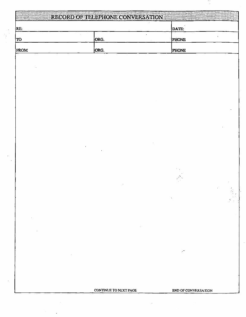
RECORD OF TELEPHOm COITOB^
RE: DATE:
TO ORG. PHONE
FROM ORG. PHONE
CONTINUE TO NEXT PAGE END OF CONVERSATION

S. S. PAPADOPULOS & ASSOCIATES. INC.
PROJECT
DRILLING I
FROM TO
IE CORD
STRATA THICK
DRILLER
DESCRIPTION REMARKS
' • )
OWNER NUMBER
DATE COMPLETED
DRILLING METHOD
CASING STRI NG -F -F -F -F -f-
" TYPE DIAM.
DEPTH -FHT ABOVE LS
MP ELEVATION
SCREEN
TYPE DIAM.
LENGTH SLOT
DEPTH SET FROM TO
GRAVEL RECORD METHOD
TYPE # OF BAGS
DEPTH BOTTOM TOP
BENTONITE SEAL
DEPTH BOTTOM TOP
GROUT RECORD
TYPE . // OF BAGS
DEPTH BOTTOM TOP
DEVELOPMENT RECORD DATE
TIME METHOD(S)
PUMPING RATE D/D
HOW MEASURED?
O T T T ? UtAD . 1
.. SITE MAP 1 y - - ; 1 i I i 1 1 1 1 : :
1 : ; : 1 1 1 ; 1 :
1 1 ; ! 1 1 : : :
i i '. '. 1 1 '
1 i t 1 i i i i 1 1
i 1 i i 1 1 : ' '
1 : i : : i i : i :
: 1 1 1 1 1 1 i ' :
' I 1 i : ! i 1 : !
< 1 1 1 i 1 1 1 .' : ;
1 1 1 1 1 ! 1 i M
1 1 ! M 1 ! :
' f i l l i !
; 1 1 , 1 • : 1
• ! ! 1 1 ,
1 — : — : — : — : — : — i 1 — 1 — I
1 1 : i M ! M
i ! : ! 1 1 i 1 1
1 1 • . : ' • 1
1 1 1 ; ; i ! 1
1 I • • ; ; 1 ! I
1 i , < 1 : ; i i
: i i : i : 1 1 i
: 1 : : 1 > 1 1 !
I 1 : : 1 I 1 i i
1 1 ' . i 1 1 1 1
1 1 ! ! i ! i 1 1
' 1 ! ' 1 : > 1 1
1 1 • 1 i 1 ; ; t i : . : 1 ' ' 1 1
M i l ; - • • M
1 • t ; 1 •• ! : 1 1
1 ' i ' 1 ' ' 1 < 1
: ; 1 : : ; • : I
1 i : ! i • ' • 1
i i i i i i : : • i : : 1 i i ' • ' • 1
1 1 1 1 1 :• : ^ i •
l i i l i l l : :
1 1 I 1 : : ; : •
1 1 ' '1 I ' l '
i 1 1 1 1 ; • ' •. :
. . : ! ; ! 1 .' ... J - _
REMARKS
WATER LEVEL
NUMBER

UJ a (A
UJ
o z li Z CC
X u a u. UJ
o z
z o
oc p UJ o
OC u 5 o a f - I o u> - I IM Z Ui Ui Q 3 a. u
LOG OF BORING No. DATE DRILLED:
DESCRIPTION:
EQUIPMENT:
ELEVATION:
oc o
z o o
o z
THIS SUMMASY APPLIES ONLT AT TME LOCATION OF THIS SORING ANO AT THE TIME OF ORILLING SUBSURFACE CONDITIONS MAY DIFFER AT OTHER LOCATIONS AND MAY CHANGE AT THIS LOCATION WITH THE PASSAGE OF TIME THE OATA PRESENTED IS A SIMPLIFICATIOU OF ACTUAL CONDITIONS ENCOUNTERED
S. S. P A P A D O P U L O S & A S S O C I A T E S . I N C .

CONSTRUCTION LOG OF WELL No.
2 ra O
ffl
> S a. Q.
<
ffl
£ ra a. o
Well Type-
Casing Type:
Casing Dia: _
Casing Lengths:
Screen Size:.
Screen Length:
Tailpipe Length:
Locking Cover Type:
Locking Cover Stickup (-i-)/Depression ( - ) :
Filter Material:
Filter Volume:
Seal Material:
Seal Volume:
Grout Material:
Grout Volume:.
Bore Dia:
Total Depth:
Comments:
DEPTH IN
FEET Date Completed:
••::••:•' » » • •
•/:•
Ji;x:->;S
GROUT
SEAL
FILTER
TME OAT* PRESENTED IS A SIMPLIFICATION OF ACTUAL CONDITIONS. THIS SUMMARY APPLIES ONLY AT TME LOCATION OF TMIS WELL AT THE TIME OF CONSTRUCTION CONDIT IONS S H O W N MAY C H A N G E WITH THE PASSAGE OF TIME.
S. S. PAPADOPULOS & ASSOCIATES. INC.

S. S. PAPADOPULOS & ASSOCIATES. INC. Field Water Level
Measurements
DATE:
PERSONNEL:
WEATHER:
PROJECT No.
HOW MEASURED/DEVICE:
LAST CALIBRATION DATE:
COMMENTS:
Time Well No.
Predicced or Measured Tide Level*
Top of Casing Elevacion (Measuring Poinc)
Depch Below Top of
Casing (MP) Wacer Level Elevacioa
* TIDE TABLE REFERENCE:

S. S. PAF'ADOPULOS ft ASSOCIATES. INC.
Date.
Project Name
Sample Location
Project No
Weather Conditions.
Observations/Comments.
Samples Collected By QUALITY CONTROL
Purging/Sampling Method.
Method to Measure Water Level
Pump Lines or Bailer Ropes: new cleaned d e d i c a t e d _ _ _
Method of Cleaning Bailer/Pump -.
pH Meter No Date Calibrated.
Sp Conductance Meter No. Date Calibrated
PURGING AND SAMPLING DATA
Water Level (below MP) Start End
Measuring Point (MP).
Water Purging & Sampling Log
Time Pump Rate (gpm)
Discharge (gallons)
pH Temp CC)
Sp Cond ttmhcs/cm)
Color Odor Turbidity
Total Discharge. Casing Volumes.
Method of Disposal of Discharge Water,
Sheet. of

s s PAPADOPULOS ft ASSOCIATES. INC S a m p l I n Q aHci A n d l y s l s R e q u e s t
Collector Date Sampled Tine hours
Affiliation of Sampler
Address .
number street city s t a t e z i p
Telephone ( ) Company Contact
LABORATORY SAMPLE COLLECTOR'S TYPE OF NUMBER SAMPLE NO. SAMPLE* FIELD INFORMATION**
Analysis Requested
Special Handling and/or Storage
PART II: LABORATORY SECTION*^
Received by Title Date
Analysis Required
* Indicate whether sample Is soil, sludge, etc. **Use back of page for additional Information relative to sample location.

S. S. PAPADOPULOS ft ASSOCIATES. INC. Field Sample Data
Date SSP&A Unique Sample No,
SITE DATA Project Name & Location
Sample Source: No. Description
Source Depth Diameter Screened In terva l
Weather Condi t ions
Comments
HNu Readings: Background Headspace Discharge
METHOD Water-Level Measurement Method
Purging and Sampling Equipment
Method o f Cleaning
pH Meter No. Cal ib ra ted
S p e c i f i c Conductance Meter No,
Thermometer Type
Cal ibrated
FIELD OBSERVATIONS Color
Discharge Measurement
Odor Turbidi ty
Depth to Water
Purge Rate
pH
Sample from
_ Date
Time
Time
Volume
Spec i f i c Conductance Temperature
PREPARATION Filter
Depth of Intake
How ?
Additives
Sample Containers
STORAGE HANDLING Shipping Container Cooling
Cour-ier
Laboratory Name & Address
REMARKS
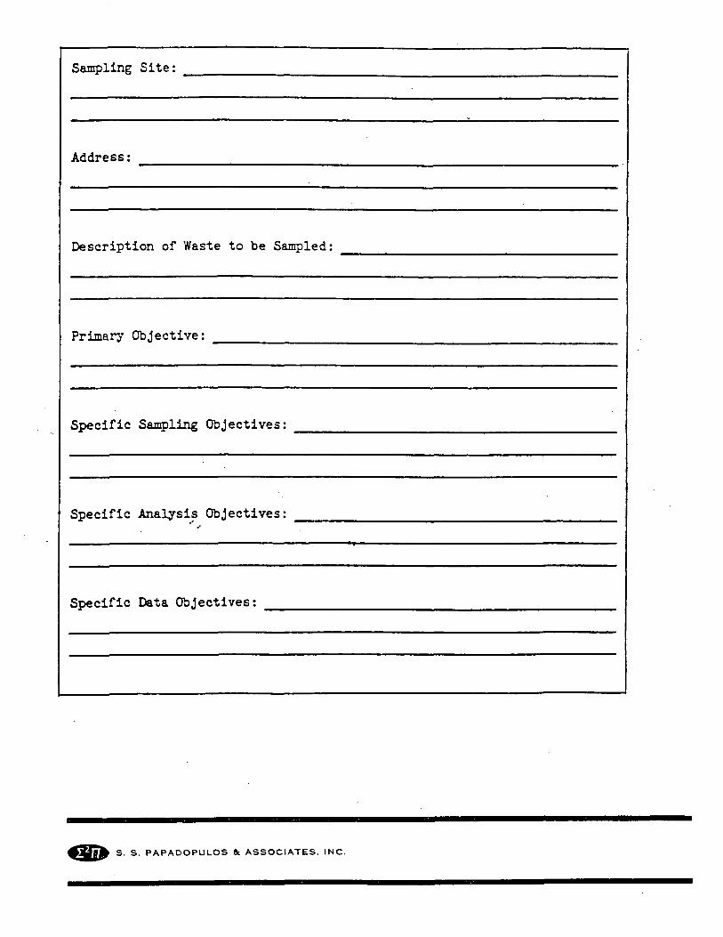
Sampling Site;
Address;
Description of Waste to be Sampled:
Primary Objective:
Specific Sampling Objectives:
Specific Analysis Objectives:
Specific Data Objectives:
S. S. PAPADOPULOS ft ASSOCIATES. INC.

S. S. PAPADOPULOS ft ASSOCIATES. INC. Chain Of Custody Record
Project No.
Date
TIME SAMPLE NUMBER
CONTAINER SIZE
ANALYZE FOR
Relinquished by: (signature)
Relinquished by: (signature)
Relinquished by: (signature)
DateyTime
Date/Time
Date/Time
Sample Point:
PRESERVATIVE
Received by: (signature)
Received by: (signature)
Received by: (signature)
HOLDING TIME
REMARKS
/
Receiver represents:
Receiver represents:
Receiver represents:

ATTACHMENT C
GROUND-WATER SAMPLING PLAN

CONTENTS
1.0 INTRODUCTION 1
2.0 WATER-LEVEL MEASUREMENTS 2
2.1 Water-Level-Measuring Equipment 2
2.2 Measurement Procedures 3
3.0 GROUND-WATER SAMPLING 5
3.1 Ground-Water Sampling Equipment 5
3.2 WeU Purging 6
3.3 Sampling Procedures 7
3.4 Sample Containers, Labeling, and Handling 8
3.5 Transportation of Samples 8
3.6 Chain-of-Custody Procedures 9

1.0 INTRODUCTION
The objective of sampling is to provide information about ground-water quality in the
immediate vicinity of the FAR-MAR-CO Subsite, Hastings Ground-Water Contamination Site,
Hastings, Nebraska. This protocol describes the procedures that will be used for collecting samples
of groimd water from, and measiuing water levels in the newly installed monitoring wells.
All samples wiU be analyzed for volatile organic compounds and ethylene dibromide, and two
or three samples will be analyzed for major cations and major anions, dissolved silica, dissolved
solids, and alkalinity. The analytical methods have been specified in the Quality Assiu'ance/Sampling
and Analysis Plan QA/SAP (Morrison-Enterprises, December 1991). In addition, specific
conductivity, temperature and pH will be measured in the field at the time each sample is coUected.

2.0 WATER-LEVEL MEASUREMENTS
Measurements of the water level in weUs serve the dual purpose of determining the slope
(gradient) and configuration of the water table or potentiometric surface, and the changes with time
of the water level in the measured weU. AU newly instaUed monitoring weUs at the FAR-MAR-CO
subsite wiU be measured for these purposes at the frequency specified in the Work Plan (M-Q, 1991).
The measuring point on each weU wiU be marked with a notch or permanent painted,
generaUy at a high point on the weU casing, and its elevation wiU be determined during the weU
survey. As the water table or potentiometric surface commonly has an average slope of about 0.01
to 0.1 (10 to 100 ft per 1,000 ft) or less, water-level measurements wiU be made to a precision of
0.01 feet in order to permit proper definition of the hydrauUc gradient.
2.1 Water-Level-Measuring Equipment
The required water-level-measuring equipment consists of:
• a tape reel with a 100- to 150-foot engineer's steel tape, preferably black, with raised
markings, graduated in feet, with at least 1 foot graduated in 1/lOOths of a foot;
• a spare tape in case of loss or breakage;
• a supply of fishing-line lead weights and swivels;
• a supply of carpenter's blue chalk (soUd); and
• an electronic water-level indicator.
A slender lead weight is attached to the ring at the end of the tape to insure plumbness and
to permit some feel for obstructions. The blue chalk is used to coat the end of the tape inserted into
the water. The electronic water-level probe is for backup purposes; it wiU be used according to
manufacturer's specifications.

2.2 Measurement Procedures
Each time a weU is approached to be measured it wUl be visuaUy inspected to make sure that
the measuring point has not been changed nor the weU vandalized. The weU wiU be measured with
a clean, decontaminated tape to protect the quaUty of the water in the weU. Before inserting the tape
into the next weU, at least 3 feet wiU be washed with detergent and water, triple rinsed with deionized
water, and wiped dry with clean paper towels. Water levels wiU be measured in each weU prior to
purging and sampling.
The approximate depth to water wiU be known within 3 or 4 feet from information on the
local hydrogeology, from previous measurements in the weU, if any, and from measiu-ements in
nearby weUs. The chalked end of the tape wiU be lowered carefuUy to within 4 or 5 feet of the
estimated water level, then one or two feet at a time to find the water surface by feel and by the
sound of the weight striking water.
The tape wiU be held so that it hangs verticaUy below the measiuing point (MP); it wiU not
be held so that the tape rubs against the inside of the casing opposite from the operator. The tape
wiU be lowered slowly, under firm control, the last couple of inches to the even foot on the measuring
point, to prevent overshooting. Also the tape wiU be held on the MP for about 3 seconds to make
certain the chalk is wetted. Care wiU be exercised that the tape does not faU below the "held" point
when beginning retrieval.
The tape wiU be retrieved, and the amount of wetted chalk wiU be recorded. During retrieval
the steel tape wUl not be drawn across the top of the casing with such force that the tape retains a
curl and wiU no longer hang verticaUy in the weU. This practice can also cause the tape to rub
against the far side of the casing, smearing the reading.
As a standard of good practice, the observer wiU make two measurements. If two
measurements of static water level made within 2 or 3 minutes do not agree within about 0.01 foot

(generaUy regarded as the practical Umit of precision), measurements wUl be continued untU the
reason for the lack of agreement is determined or until the results are shown to be reliable. The same
measuring point, which wUl be clearly marked on the casing, wiU be used for aU measurements.
At the time each water level is measured, the depth of the weU wUl be sounded, using the
same procedure and the same weighted tape. That depth wUl be recorded on the same field log and
in the same log book as the water-level measurement, along with any unusual conditions that may
have been noted.
Floating product is not expected to be encountered in any weU. In the event that floating
product is encountered, an oil/water interface probe wiU be used in that well to measure the depth to
product and water and, if possible, the product thickness.
Water levels wiU be recorded on both the field log shown in Attachment B and in the field
log book, as described in Section 9.1 of the QA/SAP.

3.0 GROUND-WATER SAMPLING
During the ground-water sampling activities, every effort wiU be made to ensure the integrity
of samples by minimizing disturbance of water being sampled that might volatUize organics.
Rigorous decontamination procedures wUl be followed to avoid any contamination of samples from
equipment used between weUs.
3.1 Ground-Water SampUng Equipment
Sufficient sampling equipment wUl be prepared and available to collect ground-water samples
from the monitoring weUs. The wells wiU be sampled using equipment and procedures that wUl not
contaminate the ground-water sample to be coUected. Clean sampling equipment wUl be wrapped
in plastic bags when brought to the weU and wUl be removed from the wrapping only prior to being
placed in the weU. If it is necessary to place equipment on the ground before it is used in the weU,
it wUl be placed on a plastic dropcloth spread on the ground to prevent contamination. Suitable
equipment for sample collection is described below:
c
• a 1,000-mL teflon baUer, equipped with a bottom-emptying valve, suspended from a
new, clean length of polypropylene rope,
• a Grundfos 316 StaiiUess Steel and Teflon Redi-Flo2 pump with Teflon tubing,
• a Johnson-Keck or equivalent submersible stainless steel pump with teflon tubing and
plastic coated electrical lines.
The choice of equipment typically depends on the depth to water and the volume of water to
be purged. The substantial depth to water at the FAR-MAR-CO subsite dictates that the wells most
likely wiU be purged with a Redi-Flo2 pump and sampled from the pump-discharge orifice. The
Redi-Flo2 pump is 1.8 inches in diameter and 11 inches taU. It is capable of a flow rate of 6 gpm
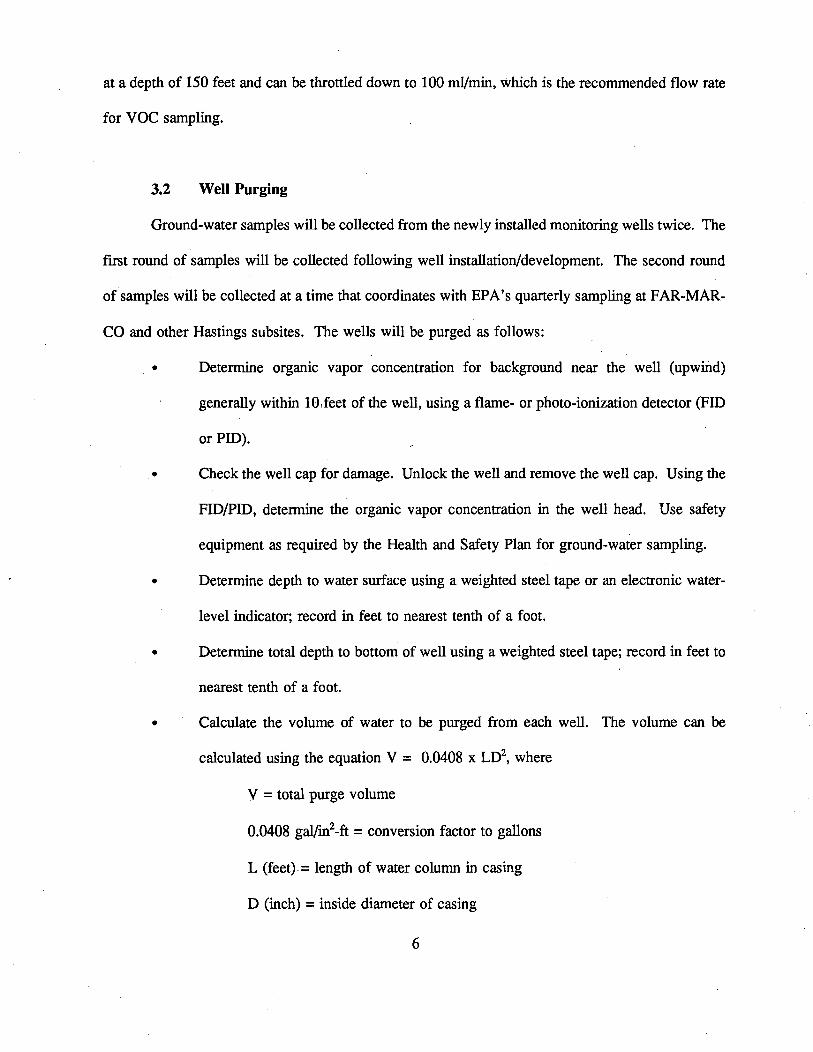
at a depth of 150 feet and can be throttled down to 100 ml/min, which is the recommended flow rate
for VOC sampling.
3.2 Well Purging
Ground-water samples wiU be coUected from the newly instaUed monitoring wells twice. The
first round of samples wUl be coUected foUowing weU instaUation/development. The second round
of samples wUl be coUected at a time that coordinates with EPA's quarterly sampling at FAR-MAR
CO and other Hastings subsites. The wells wUl be purged as follows:
• Determine organic vapor concentration for background near the weU (upwind)
generaUy within 10,feet of the weU, using a flame- or photo-ionization detector (FID
or PID).
• Check the weU cap for damage. Unlock the weU and remove the well cap. Using the
FID/PID, determine the organic vapor concentration in the weU head. Use safety
equipment as required by the Health and Safety Plan for ground-water sampling.
• Determine depth to water surface using a weighted steel tape or an electronic water-
level indicator; record in feet to nearest tenth of a foot.
• Determine total depth to bottom of weU using a weighted steel tape; record in feet to
nearest tenth of a foot.
• Calculate the volume of water to be purged from each weU. The volume can be
calculated using the equation V = 0.0408 x LD , where
V = total purge volume
0.0408 gal/in^-ft = conversion factor to gaUons
L (feet) = length of water column in casing
D (inch) = inside diameter of casing

The weUs installed during this field investigation require approximately 15 to 20 gaUons of water, to
be purged from each prior to sampling.
• Purge the appropriate volume from each weU. Specific conductance, temperature and
pH wiU be measured periodicaUy during purging to assure that water quality has
StabiUzed. Wells wiU be considered successfuUy purged when the discharge water has
chemicaUy stabilized with regard to the three monitored parameters and a minimum
of three casing volumes has been removed. If chemical stabiUty has not been attained
after four casing volumes of water have been removed, sampling can be started, and
notes wiU be made clearly describing the stabUization problem (U.S. Geological
Survey, 1989).
• For low yielding weUs evacuate to dryness once. As soon as the water level in the
weU has recovered sufficiently to obtain an adequate sample volume, coUect the
sample.
3.3 Sampling Procedures
Sampling wUl be performed using protocol that is comparable to the EPA methods described
in "RCRA Ground-Water Monitoring Technical Enforcement Guidance Document" (EPA, 1986).
Ground-water sample collection wUl be documented as described in Section 9.1 of the QA/SAP. The
sampling procedures shaU be as foUows:
• Lower the pump assembly to the depth where it is adjacent to the midpoint of the well
screen. Record the depth and time, and start the pump.
• Take periodic grab samples and measure temperature, conductivity, and pH. When
these parameters have stabUized and a sufficient volume of water has been removed

from the weU, coUect the sample from the pump-outlet orifice directly into the sample
container. FUl sample containers untU a convex meniscus forms at the top. Cap the
container, and then invert and inspect VOA vial for air bubbles in the sample. If air
bubbles are present, coUect another sample, repeating the same operations, ,untU a
bubble-free sample is obtained.
• Tum off the pump, record the time and the volume of purge water. Remove the
pump assembly from the well.
• Cap the weU, lock the well cover, and ensure no sampling equipment or discarded
sampling suppUes have been inadvertently left in the vicinity of the weU head.
• CarefuUy label, log in, and package the sample bottles in their respective coolers.
3.4 Sample Containers, Labeling, and Handling
The size and type of containers and the preservation and handling of samples wiU be
determined pursuant to EPA guidance and in cooperation with the contract laboratory. The number
and size of containers for each sample are Usted in the QA/SAP.
Sample containers wiU be properly labeled and numbered with a unique tag at the time of
sampling. The container label wUl contain the date and time of sampling, the well number, the
analysis to be performed, a unique sample number, and the initials of the sampler. Additional detaUs
on documenting ground-water-sampling procedures are contained in Section 5.0. of the QA/SAP.
3.5 Transportation of Samples
As soon as properly labeled, a sample wiU be place in a resealable plastic baggie, and then
in the shipping container with plastic bubble wrap, as necessary, for cooUng and transportation to the
laboratory. The shipping container wiU be cooled with ice or blue ice and strapped with security tape.
8

Samples wiU be shipped or carried to the laboratory by common carrier or courier, using routine
chain-of-custody procedures.
3.6 Chain-of-Custody Procedures
Samples wUl remain in the possession of field personnel from the time of coUection untU they
are turned over to a courier or common carrier for shipment to the laboratory. Should it become
necessary to refrigerate samples over night for early moming ship ping, the samples wiU be wrapped
for protection in appropriate packaging or left in the cooler and sealed with safety tape. When
retrieved, the safety tape wUl be thoroughly inspected for signs of damage or tampering.

ATTACHMENT D
STATE OF NEBRASKA, RULING OF SUBSTANTIAL EQUIVALENCE ON WELL-COMPLETION METHODS

STATE OF NEBRASKA
E. Benjamin Governor
Nelson
DEPARTMENT OF HEALTH Gregg F. Wright, M.D., M.Ed.
Director 301 Centenniai Mall South
P.O. Box 95007 Lincoln, Nebraska 68509-5007
Fax (402) 471-0383
(402) 471-2541
July 31, 1991
Ms. Claudia Stone Senior Hydrogeologist S.S. Papadopulos & Associates, Inc. 12250 Rockville Pike, Suite 290 Rockville, MD 20852
RE: Water Veil Standards - Declaratory Ruling - Monitoring Wells, Hastings Ground Water Contamination Site; Hastings, NE
Dear Ms. Stone:
This is in response to your request for a declaratory ruling received by Mike Wentink of our North Platte office, regarding construction aspects of the above-referenced proposed monitoring wells.
Based upon information submitted to this office, your proposal for alternate grouting and natural development appears to be substantially equivalent under the following conditions.
1. The lower bentonite seal shall extend upward to a point above the static water level.
2. Bentonite pellets/chips shall be placed in a manner to avoid bridging.
3. If casing is terminated above ground, casing shall extend a minimum of 12 inches above ground.
4. Borehole cuttings shall not be used as backfill material of the annular space.
5. All other requirements of Title 178, NAC 12 shall be complied with.
7. A copy of each well log shall be submitted to this office following completion of the wells.
If you have any questions, please contact this office.
Sincerely,
Rod Tremblay, Geologist Section Supervisor Water Well Standards
RT:jet An Equal Opportunity/Affirmative Action Employer
Q l ^ printed on recycled paper
Related Documents