A9TRA JET CORPORATION LETTER OF TRANSMITTAL TO: HOLDERS OF 112411124A WESTWIND MANUALS Included with the enclosed Revised Service Data Book Index Pages are current revision listings for the Westwind manuals and microfiche. Please compare these listings to your manuals to ensure they are current. It is also recommended you compare the Service Data Indexes to your Service Data Books to ensure this data is current. Please send any discrepancies or missing publication requests to: Astra Jet Corporation Technical Publications Post Office Box 10086 Wilmington, DE 19850 or FAX to: 302-324-5159, Attention: Technical Publications Post Office Box 1 0086, Wil mington, Delowore 1 9850 278 Quigley Blvd., New Costle, Delo,vore 19720 Tel. (302) 324-5150 Fox. (302) 324-5159

Welcome message from author
This document is posted to help you gain knowledge. Please leave a comment to let me know what you think about it! Share it to your friends and learn new things together.
Transcript
A9TRA JET CORPORATION
LETTER OF TRANSMITTAL
TO: HOLDERS OF 112411124A WESTWIND MANUALS
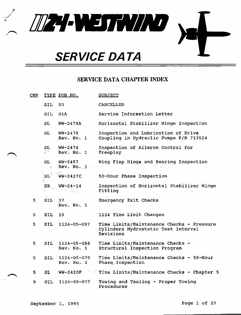
Included with the enclosed Revised Service Data Book Index Pages are current revisionlistings for the Westwind manuals and microfiche. Please compare these listings toyour manuals to ensure they are current.
It is also recommended you compare the Service Data Indexes to your Service DataBooks to ensure this data is current.
Please send any discrepancies or missing publication requests to:
Astra Jet CorporationTechnical PublicationsPost Office Box 10086Wilmington, DE 19850
or FAX to: 302-324-5159, Attention: Technical Publications
Post Office Box 1 0086, Wil mington, Delowore 1 9850
278 Quigley Blvd., New Costle, Delo,vore 19720Tel. (302) 324-5150
Fox. (302) 324-5159

61 \u: wir;9 DioT'^-
t- t c I'e . lri /. ,4a"o q I
r/a+.,,"( -^l ft eE tsd- |
+ fe, qo
/) /A 4ra 1z/ef-l
Lan 2on" D." /,
<aa(A <
tp.t - 2?- o('rfel/ a I
@ )lG/ e4 F^q7 A/J f */, /ro'te. Cdrter i" sr" I o';a'
(rc c tof6)to/1 1se /,/ a ce(l": ' (auul 0ar Cot'o"'an
P.e 7 "'r
't
/(r tt r, - t 5--oat
lla,l - 2:' 0'll
ll 'l,q - 2.1- o'{3
llLy_3y-o't-7ItaY-j'l-o6rt( t\ -tu' o qo
llJ\-p3Ll- o?q
It^y-tt- to3
ll:'( -at-ol
-{Ll_il7
to/z t/te l-br ' < ?- l' lt rz ' Tu( ' Ae7^'' a J-4f ra'cqai (frr6 a"771
6/l,,rtr, 6y 1t<ss aQ CTt(x^) Catttto/ tlc^J u't"'<e Co^rmt;
6 1 r/Cz irr-r-e r/ G,,,,a'tor T i'lJ c ;s,.urr w;rt7 y'4o Jt-ltc ct-ta t
l't/ tt/at tl)a'o' fro*" :o"" -! '-;tfovet'.tc'r -Qr Co s' &lr
atrctr+ 4att- $e(e't' vaP/Loc s t'ti+ctt'a2 J-t\y avt''"*"r'
1/?/"1 -Tce* Qc*;" PA c//E/uo fra+):Tce' esri-rct'\ po t al';/ '7
q/ tTal - ,.( AF c eo7/) . .t ^./: ce.a-a;a lalp Tnsn'"'"'t5'Fo^t I i 'o- 4 ':t - e xcha".f o o*. t
-Co^/*'/ P/P lN lloo )'na' i'o.:'
tl/e6/qc, flfatorJs + t'1'ot tirlt ''.ouiy Et s'7-rbLt nr>1 / hvtJ qeV hc"'""-
( ttc 7o7t)
e 1 t+/q2 T t,7lr cooroti ' Pet'::, Ui^]3 ,!!,',r'r,:::'tl'i lcr 'rol + wn;c4! j'lzL;l'-tzt5
I " -r. _'|-
-T ^t )Qrlt"ri / 'tAUct"a"-t
5 tr.,,- '-**-r )
,/ _ je-l(6 t ( 4t , "/ ^r '1i"e'. i"nt' t/
t f2.i/q Y La"t"'7 * 'f o tLri1 """ni
!; ""\
-; TTT{
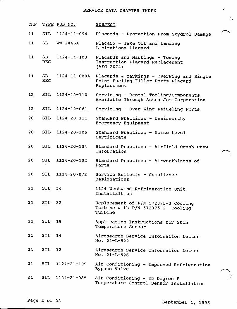
SERVICE DATA
CHP TYPE PUB NO.
SIL 03
SIL O1.A
sL wvl-24794
sL ww-2478Rev. No.
sL ww-z474Rev. No.
sL ww-2457Rev. No.
sL ww-2427C
sB wvt-24-L4
SIL
SBRVICE DATA CIIAPTER INDEX
SUBJECT
CANCELLED
Service Information Letter
Horizontal Stabilizer Hinge Inspection
Inspection and Lubrication of DriveCoupling in Hydraulic Purnps P/N 7L3524
fnspection of Aileron Control forFreeplay
Wing Flap Hinge and Bearing Inspection
50-Hour Phase Inspection
Inspection of Horizontal Stabilizer HingeFitting
Emergency Exit Checks
LL24 Time Linit Changes
Tine Limits/Maintenance Checks - PressureCylinders Hydrostatic Test IntervalRevisions
Time Lirnits/Maintenance ChecksStructural Inspection Program
Time Limits/Maintenance Checks SO-HourPhase Inspection
Tirne Limits/Maintenance Checks - Chapter 5
Towing and Taxiing - Proper TowingProcedures
5 SIL
5 SIL
37Rev. No. 1
15
LL24-05-O97
5
9
srL 1124-05-088Rev. No. 1
srL LLz4-05-079Rev. No. 2
sL ww-2420F
srL LLz4-09-077
September L, 1995 Page 1 of 23
SERVICE DATA CHAPTER INDEX
CHP TYPE PUB NO. SUBJECT
11 SIL LtzA-LL-OgA Placards - Protection Frorn Skydrol Damage
lL SL WW-2445A Placard - Take Off and LandingLinitations Placard
1l- SB 1124-11-103 Placards and Markings - TowingREC Instruction Placard Replacement
(AFC 2O7 4)
1-1 sB LL24-LL-088A Placards & Markings - overwing and singreREC Point Fueling Fi11er Ports placard
Replacement
L2 srl L124-L2-LL0 servicing - Rentar Tooling/cornponentsAvailable Through Astra Jet Corporation
L2 SIL LL24-L2-O6L Servicing - Over Wing Refueling ports
20 SIL LL24-20-l-11 Standard Practices - UnairworthyEmergency Equipnent
20 SIL L\24-20-106 Standard Practices - Noise LevelCertificate
20 SIL LL24-20-104 Standard Practices - Airfield Crash CrewInformation
20 sIL LL24-20-102 ;::l3"ru
Practices - Airworrhiness of
20 SIL LL24-2O-O72 Service Bulletin - ComplianceDesignations
2L SIL 36 LL24 Westwind Refrigeration UnitInstallaltion
21, SIL 32 Replacement of P/N 572375-3 CoolingTurbine with P/N 572375-2 CoolingTurbine
Application Instructions for SkinTemperature Sensor
Airesearch Service Information LetterNo. 2L-L-522
Airesearch Service Information LetterNo. 2t-L-526
2L SIL ]-9
2L SIL 14
2L SrL 12
2L SIL LL24-21--109 Air Conditioning - fmproved RefrigerationBypass Valve
2L srl, LL24-2r--085 Air conditioning - 35 Degree FTenperature Control Senscjr Installation
Page 2 of 23 September L, 1995
SERVICE DATA CHAPTER TNDEX
CHP TYPE PUB NO. SUBJECT
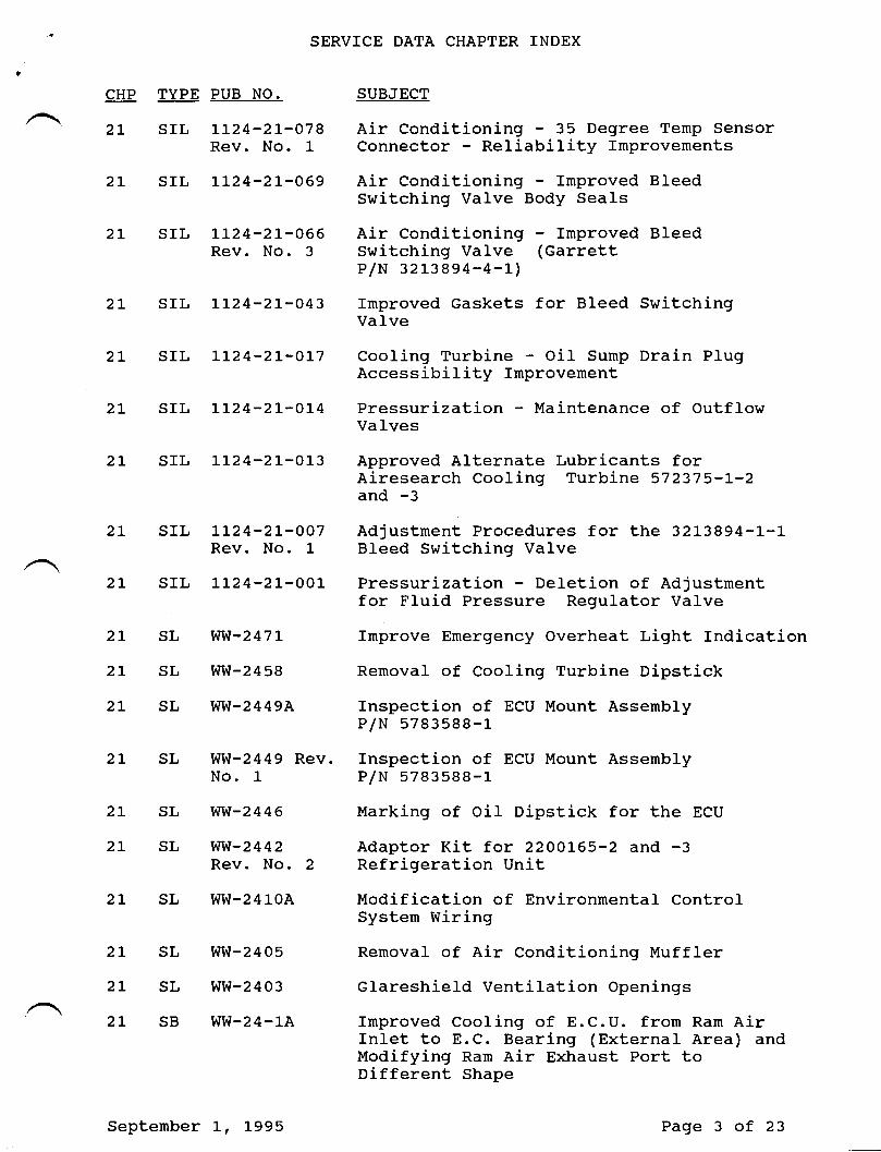
2L SIL LL24-21--078 Air Conditioning - 35 Degree Temp SensorRev. No. 1 Connector 'Reliability Improvements
2L SfL LL24-21-069 Air Conditioning - Improved BleedSwitching Valve Body Seals
2L SfL LI24-21--066 Air Conditioning - Irnproved BleedRev. No. 3 Switching Valve (Garrett
P/N 32L38e4-4-L)
2L SIL LL24-21--043 Improved Gaskets for Bleed SwitchingValve
2L SIL LL24-2L-OL7 Cooling Turbine - OiI Sump Drain PlugAccessibility Improvement
2L SIL LL24-21-01-4 Pressurization - Maintenance of OutflowVaIves
2L SfL LL24-21-013 Approved Alternate Lubricants forAiresearch Cooling Turbine 572375-L-2and -3
2L SfL Lt24-21-007 Adjustnent Procedures for the 32L3894-L-LRev. No. 1 Bleed Switching Valve
2L SIL LL24-2L-001- Pressurization - Deletion of Adjustrnentfor Fluid Pressure Regulator Va1ve
2t SL WW-247L Improve Emergency Overheat Light Indication2L SL WW-2458 Removal of Cooling Turbj-ne Dipstick
2L SL WW-2449A Inspection of ECU Mount AssernblyP/N 5783588-r_
2I SL WW-2449 Rev. Inspection of ECU Mount AssemblyNo. 1 P/N 5783588-L
2L SL VM-2446 Marking of OiI Dipstick for the ECU
2L SL VIW-2442 Adaptor Kit for 22OOL65-2 and -3Rev. No. 2 Refrigeration Unit
2L SL WW-241-0A Modification of Environrnental ControlSystern Wiring
2L SL WW-2405 Removal of Air Conditioning Muffler
2L SL WW-2403 Glareshield Ventilation Openings
2L SB WW-24-1A Improved Cooling of E.C.U. from Ram AirInlet to E.C. Bearing (External Area) andModifying Ran Air Exhaust Port toDifferent Shape
September I, L995 Page 3 of 23
SERVICE DATA CHAPTER INDEX
CHP TYPE PUB NO. SUBJECT
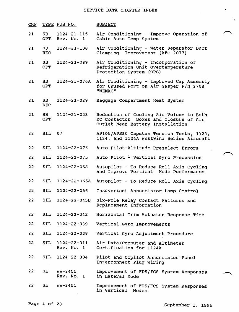
2L SB LL24-21-115 Air Conditioning - Improve Operation ofOPT Rev. No. 1 Cabin Auto Tenp Systen
2L SB LL24-21-108 Air Conditioning - Water Separator DuctREC Clarnping Improvement (AFC 2077,
2L SB LL24-21-089 Air Conditioning - Incorporation ofOPT Refrigeration Unit Overtemperature
Protection System (OPS)
2L SB LL24-21-076A Air Conditioning - fmproved Cap AssenblyOPT for Unused Port on Air Gasper P/N 27Og
ilWEMACrl
2L SB IL24-2L-O29 Baggage Compartrnent Heat SystemREC
2L SB LL24-2L-028 Reduction of Cooling Air Volume to BothOPT DC Contactor Boxes and Closure of Air
Outlet Near Battery Installation22 SIL 07 AP105/APS80 Capstan Tension Tests , LL23,
LL24, and LI24A Westwind Series Aircraft22 SIL tl24-22-O76 Auto Pilot-Altitude Preselect Errors
22 SfL It24-22-O75 Auto Pilot : Vertical Gyro Precession
22 SIL LL24-22-O68 Autopilot - To Reduce RoII Axis Cyclingand fmprove Vertical Mode Performance
22 SIL LL24-22-065A Autopilot - To Reduce Roll Axis Cycling
22 SfL IL24-22-O56 Inadvertent Annunciator Larnp Control
22 SfL Lt24-22-O458 Six-PoIe Relay Contact Failures andReplacement Information
22 SIL LL24-22-O42 Horizontal Trim Actuator Response Time
22 SIL LL24-22-O39 Vertical Gyro Improvements
22 SIL LL24-22-O38 Vertical Gyro Adjustrnent procedure
22 SfL IL24-22-OLL Air Data/Cornputer and AltimeterRev. No. 1 Certification for LL24A
22 srl LL24-22-oo4 Pilot and copirot Annunciator panelInterconnect plug Wiring
22 sL ww-2455 rmprovement of FDS/Fcs system ResponsesRev. No. i- in Lateral Mode
22 sL ww-2451 rmprovement of FDs/rcs systen Responsesin Vertical Modes
Page 4 of 23 Septernber L, 1995
SERVICE DATA CHAPTER INDEX
CHP TYPE PUB NO. SUBJECT
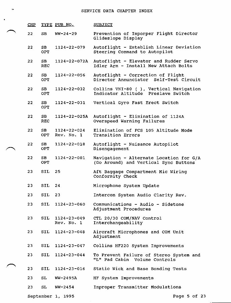
22 SB WW-24-29 Prevention of Imporper Flight DirectorGlideslope Display
22 SB LL24-22-O79 Autoflight - Establi.sh Linear DeviationOPT Steering Command to Autopllot
22 SB LL24-22-O72A Autoflight - Elevator and Rudder ServoREC ldler Arm - Install New Attach Bolts
22 SB LL24-22-O56 Autoflight - Correction of FlightoPT Director Annunci-ator Self-Test Circuit
22 SB LI24-22-O32 Collins VNI-80 ( ), Vertical NavigationOPT fndicator Altitude Preslave Switch
22 SB LL24-22-O3L Vertical Gyro Fast Erect SwitchOPT
22 SB LL24-22-025A Autoflight - Eliminatj.on of LL24AREC Overspeed Warning Failures
22 SB LL24-22-O24 Elirnination of FCS 105 Altitude ModeOPT Rev. No. 1 Transition Errors
22 SB LL24-22-01-8 Autoflight - Nuisance AutopilotOPT Disengagement
22 SB LL24-22-OOL Navigation - Alternate Location for G/AOPT (Go Around) and Vertical Sync Buttons
23 SIL 25 Aft Baggage Compartment Mic WiringConformity Check
23 SIL 24 Microphone System Update
23 SIL 23 Intercon System Audio Clarity Rev.
23 SIL LI24-23-060 Communications - Audio SidetoneAdjustment Procedures
23 SIL LL24-23-O49 CTL 2O/3O COM/NAV ControlRev. No. 1 Interchangeability
23 SIL Lt24-23-048 Aircraft Microphones and COM UnitAdjustnent
23 SIL LL24-23-O47 Collins HF22O Systern Improvements
23 SIL LL24-23-O44 To Prevent Failure of Stereo System andrrl,rr Pad Cabin Volume Controls
' 23 SIL L124-23-015 Static Wick and Base Bonding Tests
23 SL WW-2495A HF System Improvenents
23 SL V'IW-2454 Improper Transmitter Modulations
September L, 1995 Page 5 of 23
SERVICE DATA CHAPTER INDEX
CHP TVPE PUB NO. SUBJECT
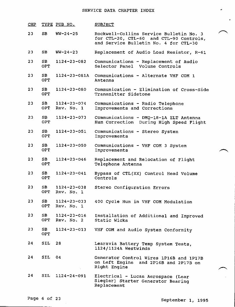
23 SB WW-24-25 Rockwell-Collins Service Bulletin No. 3 ,Afor CTL-20, CTL-60 and CTL-90 Controls,and Service Bulletin No. 4 for CTL-30
23 SB WVI-24-23 Replacement of Audio Load Resistor, R-61
23 SB Lt24-23-082 Communications - Replacement of AudioOPT Selector Panel Volume Controls
23 SB LL24-23-081A Communications - Alternate VHF COM t-OPT Antenna
23 SB Ll24-23-080 Communication Elimination of Cross-SideOPT Transmitter Sidetone
23 SB 1L24-23-O74 Communications - Radio TelephoneOPT Rev. No. 1- Improvements and Corrections
23 SB 1L24-23-073 Communications - DMQ-L8-1A ELT AntennaOPT Hum Correction During High Speed Flight,
23 SB LL24-23-051 Communications Stereo SystemOPT Improvements
23 SB 1-1-24-23-050 Communications - VHF COM 3 SystemOPT Improvements
23 SB L124-23-046 Replacement and Relocation of flightOPT Telephone Antenna
23 SB LL24-23-O4L Bypass of CTL(XX) Control Head VolumeOPT Controls
23 SB LL24-23-038 Stereo Configuration ErrorsOPT Rev. No. 1
23 sB LL24-23-033 400 cycre Hurn in vHF coM ModurationOPT Rev. No. 1
23 SB LL24-23-01-6 Installation of Additional and ImprovedOPT Rev. No. 2 Static Wicks
23 sB 1'L24-23-013 vHF coM and Audio system conformityOPT
24 SIL 2A Learavia Battery Tenp System Tests,LL24/LL24A Westwinds
24 srl, 04 Generator contror wires 1pt-6B and 1pt-78on Left Engine and 2p1GB and 2p17B onRight Engine
24 srl, 1L24-24-091- Erectricar - Lucas Aerospace (LearSiegler) Starter Generator BearingReplacement
Page 6 of 23 Septenber I, L995
24
24
24
24
24 SB WVI-24-26
24 SB WW-24-20Rev. No.
SERVICE DATA CHAPTER INDEX
SUBJECT
AC Static Inverter ImProvements
Storage of Nickel Cadniurn AircraftBatteries
Minirnizing Precipitation StaticInterference through Proper AircraftBonding
Distribution Bus Circuit BreakerInspection
Alternate Part for Engine Pylon FirewallBulkhead Connectors J313 and J314
Inspection and Test of Priority BusDiodes
Battery Switch Wiring Modification
External Power Control CircuitImprovement
Feeder Protector Relay MountingImprovements
Generator Cable Shield
One Time Inspection and Protection ofWire Bundle Routed above Cockpit OverheadCircuit Breakers
One Tirne Inspection of Wire Bundle Routedabove rrNo Smoking-Fasten Seat BeltsrlWarning Sign for Chafing
Replacement of Generator Start Contactor(csc)
External Power Fuse Replacement
General Electric DC Starter GeneratorModel 2CM5O4D2D Lirnitations and AmmeterMarkings
Removal of Zener Diodes and Resistorsfrom Air Data Power Supply Circuits
Part I - fnspection of Electrical Wiresfor Chafing Against Upper Hot LiquidContainer in calley, Part II - Reroutingof Electrical Wiring Behind Hot LiquidContainer Compartments of GaIleYP/N CMA521288
CHP TYPE PUB NO.
24 SrL LL24-24-O54
srL LL24-24-O37
srL LL24-24-O23
24
24
24
24
24
24
sIL LLz4-24-019B
srL II24-24-OO6
srL ]-L24-24-O05Rev. No. 1
sL ww-2496
sL ww-2485
sL ww-2483Rev. No. 1
sL ww-2480
sL ww-2473
24 SL WW-2467
sL ww-2461Rev. No. L
SL Wtl-242L
24
24
24 SB WW-24-27
September L, L995 Page 7 of 23
SERVTCE DATA CHAPTER INDEX
CHP TYPE PUB NO. SUBJECT
24 SB WW-24-L2 Inspection of Generator Circuit ResistorsR-11 and R-12
24 sB wvl-24-4B rnspection of Generator control unitsRev. No. L
24 SB LI24-24-L2O Electrical power Improved GroundOPT Returns
24 sB LL24-24-o75 Erectricar power - cockpit Voice andREC Rev. No. 1 Flight Data Recorder Bus Change
24 sB LL24-24-o65 DC Electricar systern - Remote circuitREC Breaker Random Tripping
24 sB Ll24-24-o54 Erectrical power - Fuer euantity and rrrOPT Rev. No. 1 Gauges to priority Bus
24 SB L124-24-O43 Starter/Generator Field Circuit WiringOPT Rev. No. 2 Modification
24 sB ]-]-24-24-008 rnstallation of Larger capacity priorityREc Rev. No. 2 Bus Diodes and Erimination of Ground
Pressure Bumps
25 srl, lL24-25-096 Equipment/Furnishings Extended overWater Operations, Safety and Survival Equiprnent
25 srl, LL24-25-095 Equiprnent/Furnishings - Monogram series15500 Toilet Maintenance
25 SIL LI24-25-059 portable Fire ExtinguishersRev. No. 1
25 SIL LL24'25-055 Sherwood Toilet P/N 205L Timer Failures25 srl, L124-25-o27 rnproved stereo speaker crarity25 srl, LL24-25-010 passenger seat Recrine control
Removal/ Insta llation Improvement
25 sL wvl-2447 rnspection of seat Belt Attaching Boltfor Looseness
25 sB ww-24-22 rnspection of pirot and copirot seatAttachrnent
25 sB L1-24-25-LL7 Equipment/Furnishing - passenger LifeOpT Vest Accessibility25 sB LL24-25-085 Equipment/Furnishings - crew seat slideOPT Release Arm Assembly Irnprovement
25 sB Lr24-25-063A Equipnent/Furnishings - Hot LiquidopT containerPage 8 of 23 September L, 1995
SERVICE DATA CHAPTER INDEX
CHP TYPE PUB NO. SUBJECT
25 SB LL24-25-OO6 Cockpit Panels Installation/ReworkREC
26 SL Ww-2499 Modification of Left Engine B1eed AirRev. No. 1 Leak Detector fnstallation
26 SB L124-26-119 Fire Protection - Inspection of Aft FireREC Extinguisher Line in Left and Right
Engine Pylons
26 SB LL24-26-O22 Fire Protection - Addition of SonalertOPT Rev. No. 2 Horn to Fire Warning System
27 SIL 18 Flap System Flex Shaft Pin ReplacementRev. No. L
27 sIL IL24-27-LO7 Flight Controls - Riqht Inboard FIapFlexible Drive Shaft Routing
27 SfL LL24-27-O7O Flight Controls Suggested SpecialtyTooling for Control Systern Free PIayMeasurement
27 SIL LL24-27-064 Horizontal Trirn Actuator - Axial PIay
27 SIL LL24-27-O63 To Announce the Availability of a New EMIFilter
27 SIL LL24-27-O57 Rudder and Tabs Synchronization of DuaIActuators
27 SfL LL24-27-O3O Measurement Limits of Aileron Trirn andRev. No. 1 Servo Tab Free Play
27 SIL LL24-27-o28 FIap Limit Switch ReplacementRev. No. 1
27 SIL LI24-27-OO2 Flap Asymrnetry Comparator Control BoxFailures and Nuisance FIap ImbalanceWarnings
27 SL WW-24105 Fliqht Controls - Horizontal StabilizerAura1 Warning Horn Replacement
27 sL WW-2493 Replacement of Both Flap LinearRev. No. 2 Potentiometers P/N 4 833523-1 with New
P/N 4 833s23-50r-
27 SL WW-2489A Horizontal Trin Electrical WiringModification
27 SL WW-2464 Replacernent of Trirn Tab Actuator Rod EndRev. No. 1 Assy
27 SL WW-2448 Flap Gear Box - Position TransrnitterProtection
September L, 1995 Page 9 of 23
SERVICE DATA CHAPTER INDEX
CHP TYPE PUB NO. SUBJECT
27 sL ww-2424D rnspection and Lubrication of wing FlapFlexible Drive-Shafts
27 sL ww-2423 FIap Control Circuit Breaker Replacernent
27 sB ww-24-19 rnspection of Aileron contror purreyP/N 3533O32-L
27 SB Ww-24-Ll- Replacement of Aileron Control Chain AssyP/N 3533516-l- and SprocketP/N 2533049-501_ in Flight Control Columns
27 SB LL24-27-L29 Flight Controls - Aileron Push-Pull TubeMAN and Guide Roller fnspection
27 SB LL24-27-LO4 Flight Controls - Relocate BondingREC Rev. No. 2 Jurnpers Between Horizontal and Vertical
Stabilizers and Control Surfaces(AFc t-056)
27 SB LL24'27-Loo Flight Controls - Replacement of Left andMAN Rev. No. 2 Right Aileron contror Rod Assembries
P/N 513506-503
27 SB Ll24-27-O95 Flight Controls F44-L4 Rod-EndsREC Inspection/Replacement
27 sB LL24-27-o86 Flight contrors rnspection and/orREC Replacement of LH and RH Elevator
Reducer Tube Collars
27 SB L124-27-O62 F1ight Controls Speed BrakeREC Inadvertent Deployment
27 sB LL24-27-j6L Friqht controls - wing Flap Actuators,OPT Improvement/Repair
27 SB LL24-27-OL7 Flight Controls - Modification of RudderREC Servo Trim Tab
27 sB Lr24-27-oL2 Flap Acatuator rmprovement and Repair
27 sB LL24-27-oo3 Fright contrors Frap Vane rnspection28 SrL 30 Use of BIOBOR@JF Fuel Additive
Rev. No. L
28 SIL 2OB Intertechnique Fuel Boost pumps,P/N 5653744-I, -501_ and -503 -grush Inspection
28 SIL l7 LL24 Westwind FueI Management procedure
28 srl, L124-29-Lo3 Fuer rmproved Fuer Boost purnpRev. No. 1
28 srl 1L24-28-o9o Fuel FueI Dunp Stop Level Switch precautionsPage 10 of 23 september I, 1995
SERVICE DATA CHAPTER INDEX
CHP TYPE PUB NO. SUBJECT
28 SIL LL24-28-O62 To Announce the Availability of a NewFueI Vent Valve
28 SIL LL24-28-O26 Replacement of Firewall FueI Shut-OffValve Light Circuit RelaY
28 SIL LL24-28-O2OA FueI - Durnp Valve fnterchangeability
28 SIL LL24-28-OO9 Wing FueI Probe Gasket, Left and RightOutboard
28 SL WVI-2472 fnstallation of Cable Clanp on Fuel BoostPump Ground Wires
28 sL Ww-2436 fnstallation of Additional Wiring in FueIMeasurement System
28 SL WW-2434 Retrofit Installation of Redesigned FueISump and New Main Boost Punps
28 SL WW-24L8 FueI Vent Valve SeaI Replacernent
28 SL WW-24L2 Engine FueI Cornputer-Filter Installation
28 SB LL24-28-LO6 Fuel - Tip Tank Sealing of Float SwitchREC Wire Conduit
28 SB LL24-28-098 FueI - Preventing FueI Spillage throughOPT Vent Systern During Refueling or Transfer
Operations (AFC 2O74)
28 SB LL24-28-087 Fuel - Removal of EMI Filters fromREc Intertechnique Boost Pump Circuit
28 SB IL24-28-O83 Fuel - Modification of FueI Transfer Punp
28 SB LL24-28-O78 Fuel - FueI Status System ImprovementsOPT
28 SB LL24-28-O35 Elinination of Erratic FueI QuantityOPT Rev. No. 1 Indications
28 SB 1L24-28-OO2 Inspection of FueI Surnp Check Valve LeverREC Rev. No. l- and Installation of Manual Lever Handle
Stop
29 SIL LL24-29-LOB Hydraulic Power Self-Sealing Couplings(Quick-Disconnects) Basic Overhaul Manual
29 SIL L124-29-074 Hydraulic - Approved Use of TeflonBack-Up O-Rings
29 SIL Lt24-29-O67 Hydraulic Power Suggested Inspectj-onMethods for Aft Fuselage (Station 316)Hydraulic Lines
Septernber L, 1995 Page 11 of 23
CHP TYPE
29 SIL
PUB NO.
tLz4-29-OsL
SERVICE DATA CHAPTER INDEX
SUBJECT
Hydraulic Power Emergency HydraulicPurnp Shaft Seal Drain Fitting - ProperInstallation InstructionsHydraulic Hose Inspection
Retrofit to Ernergency Hydraulic PurnpP lN 4713010-503
Modification of Hydraulic QuickDisconnect Fitting InstallationOne Time Inspection and Installation ofTie-Wrap on Hydraulic Tubes in Wing RootAdjacent to Wing Rib (sTA. Xw-33. ooo)
Hydraulic Systern Attenuator fnstallation
Installation of Additional Check Valvesinto Hydraulic Reservoir PressurizationSource
Hydraulic Reservoir StandpipeModification - Installation of AdditionalFilter Gasket and Replacement of FilterElement
Chafing of Tubes near R.H. Engine pylon
Chafing of Tubes in L.H. Engine pylon andRelocation of Nitrogen Gauges andCharging Valves
Engine Driven Hydraulic purnp Bypass portPlug Replacement
Emergency Hydraulic Purnp protective CoverInstallation
Ice and Rain Protection Engine Hp Bleedrnanifold Assembly
Pitot and AOA Heat LirnitationsPower Plant - Inspection and Replacementof crumman Engine fnlet Anti-fce ValvesManufactured by Sterer Engineeringand Manufacturing Co., Serial Numbers001- through 478
Removal of Vertical Stabilizer DeicerBoot
SL29
SL
SL
29 SL
29 SL
29 SBOPT
30 SIL
30 SIL
30 sL
ww-2492
ww-2482Rev. No. 1
ww-2481
ww-2466
ww-2429Rev. No. 1
ww-2415
29
29
29
29
29
29
29 SL
sL ww-24t tB
ww-24-10Rev. No. 1
ww-24-6
ww-24-5Rev. No. L
LL24-29-01_4Rev. No. 1
LL24-3 0-080
rLz4-3 0-003
hn^f-24106
SB
SB
SB
30 sL ww-2465
Page L2 of 23 September L, 1995
SERVTCE DATA CHAPTER INDEX
CHP TYPE PUB NO. SUBJECT
' \ 30 SL ww-24s6 Pitot Heat off Warning Light Installation
30 SL WW-2444 Replacement and/or Rewiring of NAC/ENGAnti-Ice Control Switches
30 SL WW-2430 Re-Calibration of Deice High PressureSwitch
30 SL WVI-2425 Installation of Additi.onal Purging HoIein Birdproof Windshield
30 SB LL24-30-O9O Ice and Rain - NAC/ENG Anti-fce - SwitchoPT Rev. No. 1 Reliability (AFc 2o7t)
30 SB LL24-30-066A Ice and Rain Protection AOA and SAT TASREC Rev. No. 1 Probes Heat Wiring Improvement
30 SB LL24-30-036 Ice and Rain, PART I Windshield HeatREC Rev. No. l- Control Wiring Modification, PART II
Windshield Heat Cycling Contractorrnspection and/or Replacement
31 SIL 1-124-31-093 Indicating - Recording Systerns - CockpitVoice Recorder Underwater Acoustic BeaconFieId Maintenance
32 SIL 31A Replacement of Brake Assembly to AxleMounting Bolts
32 SIL 27 Upper and Lower NLG Bearing Precautj-ons
32 SIL LL CoId Weather Tire Precautions
32 SIL 05 Nose Wheel Steering System
32 SIL LL24-32-100 Landing Gear - Wheel Inspection AndOverhaul Schedules
32 SIL LL24-32-O98 Landing Gear - Nose Wheel Bolt HoleRepair
32 SIL LL24-32-O89 Landing Gear - MLG Tire Shoulder Cracks
32 SIL 1L24-32-O41 Goodyear Nose Gear Bearing Seals
32 SIL LL24-32-O33 Main/Nose Landing Gear - Revised LimitSwitch Adjustnents
32 SIL LL24-32-O22 Steering Yoke - Grease FittingReplacement
32 SL WW-24107 Landing Gear - Addition of OptionalAnti-skid Indicator Lights
32 SL WW-24L03 Inspection and Replacement of BrakeAssernbly to AxIe Mounting Bolts
September I, L995 Page l'3 of 23
32
CHP TYPE
32 SL
32 SL
32 SL
SL
32 SL
32 SL
SL
SL
32 SL
32 SL
32 SL
32
32
SB
SB
32 SBOPT
32 SBREC
Page L4 of
PUB NO.
ww-24 101
ww-24 L00
ww-2494Rev. No. 3
ww-2491Rev. No. 1
ww-2488
ww-2486
ww-2477Rev. No. 1
ww-2439A
ww-24 3 1
ww-2428Rev. No. 1
ww-2426Rev. No. 1
ww-24 13
ww-24098
ww-2402Rev. No. 1A
ww-2 4-28ARev. No. 1
ww-24-15Rev. No. 1
ww-24-9Rev. No. 1
LL24-3 2-110
LL24-32-LO5Rev. No. 1
23
SERVICE DATA CHAPTER TNDEX
SUBJECT
Typical Repairs for MLG Strut Door
58 Degree Nose cear Steering Modification
One Time Replacement of MLG ActuatingCylinder Inboard Attach Bo1ts, Inspectionof Inboard and Outboard MLG ActuatingCylinder Attach Points and LubricationRequirements for the Attach Points
Inspection and Lubrication of NLG Upperand Lower Outer Body Bearings and UpperBearing Retaining Nut SeaI Improvement
Goodyear Service Bulletin LL24-32-3
Moisture Drain for Main Landing GearAxIes
Nose Landing Gear Door Bellcrank AttachBoIt Check
Availability of Improved Main LandingGear Piston Plug and Retaining BoIt
Installation of Brake Wiring SupportBracket
Gear Horn Override System Installation
Nose Wheel Steering SensitivityImprovement
Wire Chafing in Nose Gear WelI
Nose Gear Steering Rol1 pin Replacementat Steering Wheel and Universal JointMain Landing Gear - ParallelisrnRequirements
Landing Gear-fnspectin of Nose LandingGear Outer Strut-Body Forging
Power Brake Valve - Replacement of poppetRetainer Pin P/N 117W50D12
Modification of Main Landing Gear
Landing Gear - Ernergency Gear Down Handle
Landing Gear - Nose Landing Gear DoorModification (AFC 1055)
32
32
SL32
32
32
32
Septenber I, 1995
SERVICE DATA CHAPTER INDEX
CHP TYPE PUB NO. SUBJECT
32 SB LI24-32-O96 Landing Gear - F44-14 Rod-EndsREC Inspection/Replacement
32 SB LI24-32-O94 Landing Gear - Selector Valve Arm -REC Secure RoII Pin (AFc 2063)
32 SB IL24-32-O45 Inspection of MLG Actuating CylinderREC Rev. No. 1 fnboard Rod-End Bearings and Attach Bolts
32 SB LL24-32-O3O Rerouting of Nose Landing Gear WiringOPT Rev. No. 1 Harness
32 SB 1L24-32-oo9 Gear Warning Horn Autonatic DisableOPT
33 SIL LL24-33-l0L Lighting - Alternate Cockpit Map Light
33 SfL LL24-33-099 Lights - Cabin Fluorescent Support SystemParts Upgrade/Replacement
33 SIL Ll24-33-099 Lights - Cabin Fluorescent Support SysternRev. No. 1 Parts Upgrade/Replacement
33 SIL LL24-33-084 Lighting - Tip Tank Strobe Light Wiring
33 SIL LL24-33-058 Electrical Noise Radiation from CabinFluorescent Lighting Systern
33 SIL 1124-33-032 Lighting - Cockpit Glareshield -Floodlight Improvement
33 SIL LL24-33-O25 Failure of Aircraft System and Lamp TestRev. No. L Function
33 SIL LL24-33-008 Staco Switch and Lamp Assemblies
33 SL WW-2484 Deletion of Glareshield Lighting ForwardRev. No. 1 Pressure Bulkhead Connector
33 SL WW-2463 Replacement of PS-274A Power Supp1y (MFG.Rev. No. 1 EMP) with Power Supply LT-52A (MFG. KGS)
33 SL WVI-24L7 Drainage for Upper Anti-Collision LightMechanism
33 SB I124-33-L22 Lights - Tip Tank Strobe Light WiringREC Conduit
33 SB LL24-33-L21 Lights - Cabin Fluorescent LightingREC Support Systern Improvement
33 SB lL24-33-069 Lights - Change in Power Source for CabinOPT Lighting Systen
33 SB Lt24-33-050 Lights Instrument Light Intensity andOPT Dimmer Balance
Septernber L, L995 Page 15 of 23
SERVICE DATA CHAPTER INDEX
CHP TYPE PUB NO. SUBJECT
33 SB LL24-33-058 Lights Corrections and fmprovements tooPT Rev. No. 2 Dinning Systern for Avionics Digital
Displays
33 SB lL24-33-034 Logo Light ModificationOPT Rev. No. 1
33 SB LL24-33-010 Emergency and Entrance Light ModuleREC Rev. No. 2 Corrections
34 SIL 35 Vibration Level for #Z Altineter
34 SIL 34 Internittent Collins Rack MountConnectors
34 SIL 26 #L or #Z Cornpass Systern - DG SwitchModification
34 SrL 22 Sperry GH14A/B Attitude GyroInstallations
34 SIL 2L NCS3]-A Read Out Problems
34 SIL L3 Rockwell-Co1lins WXR300 Radar SystemRev. No. 1 Dessicant Replacernent
34 SIL l-0 Ledex Rotary Solinoid FailureRev. No. 2
34 SIL 09 Reduction of Pitch Bumps, LL24 WestwindSeries
34 SfL 08 Manual VOR/RNAV Select, LL24 WestwindSeries
34 SIL 06 ADF 60 Accurdcy, 1-L24 Westwind Series
34 SIL LL24-34-LL2 Navigation - Weather Radar Antenna
34 SIL LL24-34-086 Navigation - Weather Radar AntennaRev. No. 1
34 SIL IL24-34-O73 Weather Radar - Collins IND-300 WeatherRev. No. 1 Radar Tndicator Mandatory Service
Bulletin34 srl, LL24-34-053 FMS-90/LRN-85/cNS-s00 Backlighting34 SfL LL24-34-052 NCS/FMS Electro-Magnetic Interference
Rev. No. l- Problems
34 SIL LL24-34-O5O HSf-84/REU-84 Modification/Status Changes
34 SIL tL24-34-O46 NCS3l/A Slant Range Correction34 srl LL24-34-o4o Radar stabirization rmprovements
Fage 16 of 23 September L, 1995
SERVICE DATA CHAPTER TNDEX
CHP TYPE PUB NO. SUBJECT
34 SIL LL24-34-O36 AOA System - Component Replacernent
34 SIL LL24-34-O3l-A Pilot and Copilot Annunciator Panel CableRev. No. 1 Bundle Chafing/Shorting
34 SIL LL24-34-O2L Installation of Chafe-Guard Material onWire Bundles at Station 269 NearEmergency Gyro Power SuPPlY
34 SIL Ll24-34-012 Coaxial Cable ClanpingRev. No. 1
34 SL hnd-241.08 Navigation - Improved Pitot/Static SystenDrain
34 SL WW-2460A Navigation Equipment - Installation ofGuard to Prevent GNS 500A RCU MountingLatch Interference
34 SL WW-2453 Reduction of Noise Spillover into AudioSystem
34 SL WVI-2452 Improvement in System Reliability andRev. No. 1 Operation (NCS3L/3LA)
34 SL WW-2422 Angle of Attack AdjustmentRev. No. l-
34 SL WW-24L4 Inspection of Angle of Attack Indexes
34 SB IL24-34-109 Navigation - Static Port Tubing SlopeoPT Inspection and Correction
34 SB Lt24-34-O99 Navigation - Pitot Head Exchange ofREC Certain Aero Instruments Company
P/N PHl100 Pitot Heads
34 SB IL24-34-O7L Navigation - Copilot's Altirneter PartREC Rev. No. 1 Number Changes
34 SB Lt24-34-O7O Navigation - VLF/Onega ReceiverOPT Performance Improvement
34 SB LL24-34-O67 Navigation - Retrofit of Collins VerticalOPT Gyro(s) and frnproved Vertical cyro Mounting
34 SB LL24-34-O64 Navigation - Repeat VOR/LOC SwitchingOPT Rev. No. 1 Improvements
34 SB LL24-34-O57 Navigation - NCS-31 Display and LogicOPT Rev. No. 1 Power Supply Improvements
34 SB 1L24-34-055 Navigation - FMS-90/LRN-85 ImprovementsREC
Septernber L, 1995 Page L7 of 23
SERVICE DATA CHAPTER TNDEX
CHP TYPE PUB NO. SUBJECT
34 SB LL24-34-053 Navigation - Compass and ADF/RMI SystemOPT fmprovements
34 SB lL24-34-O52 Navigation - Glideslope Raw DataOPT Scalloping
34 SB LL24-34-O49 Navigation - Radar WaveguideOPT Pressuri-zation and Installation of Silica
GeI Container Assembly
34 SB lL24-34-O48 Collins VNI-80 VerticalNavigationOPT Rev. No. 1 Indicator Operation Improvement
34 SB 1L24-34-O47 Navigation - Static Source ImprovernentREC Rev. No. 1 for Copilot's Altiineter
34 SB LL24-34-O44 33LA-9c HSI Distance Display ImprovementsOPT Rev. No. 1
34 SB LL24-34-039 Navigation FPA-80 Option ImprovementsOPT
34 SB II24-34-O27 Enable GNS-500A Series 38 Bank CommandOPT Option for Flight Director Systern
34 SB LL24-34-O23 Navigation - Elimination of lrnproper MachREC Warnings
34 SB ll24-34-Ol-5 VOR/LOC Antenna Bonding and PhasingOPT Rev. NO. l-
35 SfL IL24-35-087 Oxygen Eros Mc-Series Mask - RegulatorAssembly Service Bulletin MA/B/CL0-35-29
35 SIL LL24-35-083 Oxygen Shutoff Valve Lubrication35 SIL LL24-35-082 Oxygen-EROS MC-series Mask-Regulator
Assembly Overhaul fnterval fncrease
35 SIL 1L24-35-035 Stowage of Eros Oxygen MaskP/N MC-1013-12
35 SIL LL24-35-015 Oxygen Systern - Time Unit Changes
35 SL WW-24104 Installation of Surge Valve in PassengerOxygen Systen
35 SB LL24-35-o77 oxygen - Cabin Altitude Pressure Switch -OPT Remote Test Connection Installation39 sL Ww-2475 Installation of Diode in Flap Contactor Box
39 SL WW-2468 Inspection of Leach Re1ay SocketRev. No. 1 P/N So-1059-89L2
Page 18 of 23 September L, 1995
SERVICE DATA CHAPTER INDEX
CHP TYPE PUB NO. SUBJECT
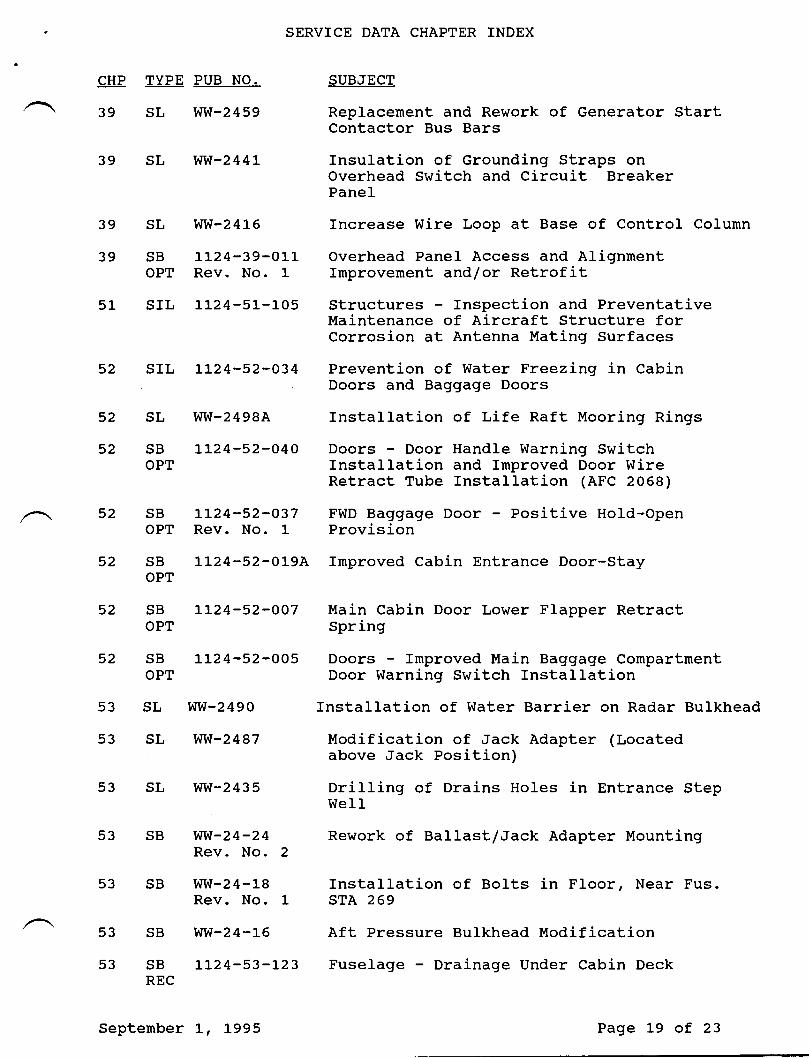
39 SL WW-2459 Replacernent and Rework of Generator StartContactor Bus Bars
39 SL rtIW-244L Insulation of Grounding Straps onOverhead Switch and Circuit BreakerPanel
39 SL WW-2416 Increase Wire Loop at Base of Control Column
39 SB LL24-39-OLL Overhead Panel Access and AlignmentOPT Rev. No. 1 Improvement and/or Retrofit
51 SIL 1124-51-105 Structures Inspection and PreventativeMaintenance of Aircraft Structure forCorrosion at Antenna Mating Surfaces
52 SIL LL24-52-O34 Prevention of Water Freezing in CabinDoors and Baggage Doors
52 SL WW'2498A Installation of Life Raft Mooring Rings
52 SB LL24-52-O4O Doors Door Handle Warning SwitchOPT Installation and fmproved Door Wire
Retract Tube Installation (AFC 2068)
52 SB LL24-52-O37 FWD Baggage Door - Positive Hold-OpenOPT Rev. No. 1 Provision
52 SB 1L24-52-019A fnproved Cabin Entrance Door-StayOPT
52 SB IL24-52-OO7 Main Cabin Door Lower Flapper RetractOPT Spring
52 SB L124-52-005 Doors Improved Main Baggage CompartmentOPT Door Warning Switch Installation
53 SL WW-2490 fnstallation of Water Barrier on Radar Bulkhead
53 SL WW-2487 Modification of Jack Adapter (Locatedabove Jack Position)
53 SL WW-2435 Drilling of Drains Holes in Entrance StepWell
53 SB WVI-24-24 Rework of Ballast/Jack Adapter MountingRev. No. 2
53 SB WW-24-18 fnstallation of Bolts in Floor, Near Fus.Rev. No. l- STA 269
53 SB WW-24-l-6 Aft Pressure Bulkhead Modification
53 SB LL24-53-L23 Fuselage - Drainage Under Cabin DeckREC
September 1, 1995 Page 19 of 23
SERVICE DATA CHAPTER TNDEX
CHP TYPE PUB NO. SUBJECT
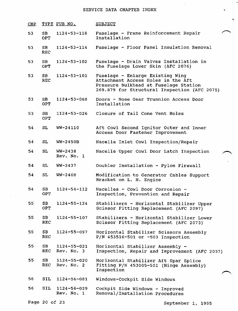
53 SB LL24-53-118 Fuselage - Frame Reinforcement RepairOPT Installation
53 SB LL24-53-114 Fuselage - Floor Panel Insulation RemovalREC
53 SB LL24-53-LO2 Fuselage - Drain Valves Installation inOPT the Fuselage Lower Skin (AFC 2076)
53 SB 1l-24-53-1-01 Fuselage - Enlarge Existing WingREC Attachment Access Ho1es in the Aft
Pressure Bulkhead at Fuselage Station269.879 for Structural Inspection (AFC 2075)
53 SB 1124-53-068 Doors - Nose cear Trunnion Access DoorOPT Installation
53 SB L124-53-O26 Closure of TaiI Cone Vent HolesOPT
54 SL WW-24L1-O Aft CowI Second Ignitor Outer and InnerAccess Door Fastener fmprovement
54 SL WW-24508 Nacelle fnlet CowI Inspection/Repair
54 SL WW-2438 Nacelle Upper CowI Door Latch InspectionRev. No. 1
54 SL WW-2437 Doubler Installation - Pylon Firewall
54 SL WW-2408 Modification to Generator Cables SupportBracket on L. H. Engine
54 SB LL24-54-LL2 Nacelles - Cowl Door CorrosionOPT fnspection, Prevention and Repair
55 SB LL24-55-t24 Stabilizers - Horizontal Stabilizer UpperOPT Scissor Fitting Replacement (AFC 2097)
55 SB LL24-55-l-07 Stabilizers - Horizontal Stabilizer LowerREC Scissor Fitting Replacement (AFC 2073)
55 SB LL24-55-O97 Horizontal Stabilizer Scissors AssenblyREC P/N 4535L6-501_ or -503 Inspection
55 SB LL24-55-O2L Horizontal Stabilizer Assembly -REC Rev. No. 3 fnspection, Repair and fmprovement (AFC 2037)
55 SB LL24-55-O2O Horizontal Stabilizer Aft Spar SpliceREC Rev. No. 2 Fitting P/N 453005-501 (Hinge Assernbly)
Inspection
56 SIL 1L24-56-081 Windows-Cockpit Side Windows
55 SIL LL24-56-O29 Cockpit Side Windows ImprovedRev. No. 1 Removal/Installation procedures
Page 20 of 23 September L, Lg95
SERVTCE DATA CHAPTER INDEX
CHP TYPE PUB NO. SUBJECT
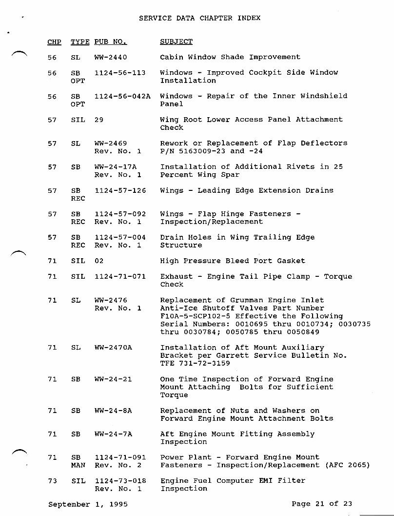
/ \ 56 SL WW-244O Cabin Window Shade Improvement
56 SB LI24-56-LL3 Windows lrnproved Cockpit Side WindowOPT Installation
55 SB LL24-56-}42A Windows - Repair of the Inner WindshieldOPT PANEI
57 SIL 29 Wing Root Lower Access Panel AttachrnentCheck
57 SL WVI-2469 Rework or Replacernent of FIap DeflectorsRev. No. l- P/N 51-63009-23 and -24
57 SB WW-24-17A Installation of Additional Rivets in 25Rev. No. 1 Percent Wing Spar
57 SB LL24-57-I26 Wings - Leading Edge Extension DrainsREC
57 SB LL24-57-O92 Wings FIap Hinge FastenersREC Rev. No. 1 Inspection/Replacement
57 SB LL24-57-OO4 Drain Holes in Wing Trailing EdgeREC Rev. No. 1 Structure
7L SIL 02 Hiqh Pressure Bleed Port Gasket
7L SIL LL24-7L-O71 Exhaust Engine Tail Pipe Clanp - TorqueCheck
7L SL WW-2476 Replacement of crumnan Engine InletRev. No. 1 Anti-Ice Shutoff Valves Part Number
FI-0A-5-SCPL02-5 Effective the FollowingSerial Numbers: 00L0695 thru 00LO734; 0030735thru 0030784; 0050785 thru 0050849
7L SL WW-2470A Installation of Aft Mount AuxiliaryBracket per Garrett Service Bulletin No.TFE 73L-72-3Is9
7L SB WW-24-2L One Tirne Inspection of Forward EngineMount Attaching Bolts for SufficientTorque
7L SB WW-24-8A Replacement of Nuts and Washers onForward Engine Mount Attachment Bolts
7L SB WW-24-7A Aft Engine Mount Fitting AssernblyInspection
7L SB LL24-71--09L Power Plant Forward Engine MountMAN Rev. No. 2 Fasteners Inspection/Replacement (AFC 20651
73 SIL LL24-73-01-8 Engine FueI Conputer EMI FilterRev. No. l- Inspection
September L, l-995 Page 2L of 23
SERVICE DATA CHAPTER INDEX
CHP TYPE PUB NO. SUBJECT
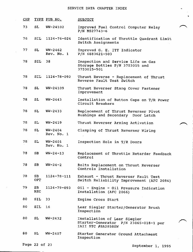
73 SL WW-241O2 Improved Fuel Control Computer RelayP/N MS27743-6
76 SIL L124-76-024 Identification of Throttle Quadrant LirnitSwitch Assignments
77 SL WW-2462 Improved G. E. fTT IndicatorRev. No. 1 P/N 688362L-503
78 SIL 38 Inspection and Service Life on GasStorage Bottles P/N 3753015 and37 53015-501
78 srl, LL24-78-o92 Thrust Reverse - Replacement of ThrustReverse Fault Test Switch
78 SL WW-241-09 Thrust Reverser Stang Cover FastenerImprovement
78 sL ww-2443 rnstalration of Button caps on T/R powerCircuit Breakers
78 SL WW-2433 Replacernent of Thrust Reverser pivotBushings and Secondary Door Latch
78 SL WW-241-9 Thrust Reverser Arming Activation78 SL WW-2404 Clamping of Thrust Reverser Wiring
Rev. No. 1
78 SL WW-2401 Inspection HoIe in T/R DoorsRev. No, 1
78 SB WW-24-l-3 Replacernent of Throttle Retarder FeedbackControl
78 sB ww-24-2 Bolts Repracement on Thrust ReverserControls fnstallation
78 sB LL24-78-LLL Exhaust - Thrust Reverser Faurt restoPT switch Reliabirity rmprovement (AFc 2oB4)
79 sB tL24-79-093 oit Engine - oir pressure rndicationREc Installation (AFC 2066)
80 SIL 33 Engine Cross Start80 srl., L6 Lear siegler starter/Generator Brush
Inspection
80 SL WW-2432 Installation of Lear Siegler ,^.Starter-Generator p/N 23065-018-L perIAII STC #SA2858SW
80 sL ww-24o7 starter Generator Ground Attachmentfnspection
Page 22 of 23 Septernber L, Lggs
SERVICE DATA CHAPTER INDEX
CHP TYPE PUB NO. SUBJECT
, 80 SL WW-2406 50 Hour Inspection of General ElectricRev. No. 1 Model 2CVI5O4D2D Starter-Generator's
Brushes and Commutators
80 SB WW-24-3 Installation of Frame Block for ExternalRev. No. 1 Ground to Starter-Generator
Septernber L, 1995 Page 23 of 23
( nI{SERY'CEINFORMATION LETTER
NO.
tr24-2r-wr
rt24-27-002
t124-30-003
tt24-22404
l124-24-005Rev. No. 1
IL24-24-006
rr24-2t-007Rev. No. 1
1124-33-008
r124-28-009
1,124-254t0
tt24-22-0tlRev. No. I
tL24-34-0t2Rev. No. I
DATE
Mar 15/84
Nov 9/84
Nov 19/84
Dec 3/84
Jun 20/85
Dec 1l/84
Aug 9/85
Dec 18/84
Dec 13/84
Dec 18/84
Feb 17186
Apr 5/85
SBRVICE INFORMATION LETTER INDEX
SUBJEC'T
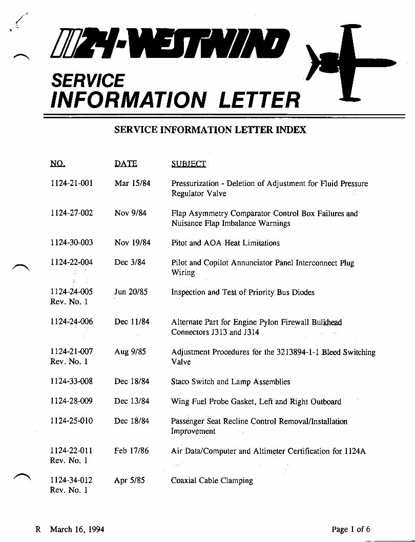
Pressurization - Deletion of Adjustment for Fluid PressureRegulator Valve
Flap Asymmetry Comparator Control Box Failures and
Nuisance Flap Imbalance Warnings
Pitot and AOA Heat Limitations
Pilot and Copilot Annunciator Panel Interconnect PlugWiring
Inspection and Test of Priority Bus Diodes
Alternate Part for Engine Pylon Firewall Bulk{readConnectors J313 and J314
Adjustment Procedures for the 3213894-1-1 Bleed SwitchingValve
Staco Switch and Lamp Assemblies
Wing Fuel Probe Gasket, Left and Right Outboard
Passenger Seat Recline Control Removal/InstallationImprovement
Air Data/Computer and Altimeter Certification for ll24|
Coaxial Cable Clamping
R March 16, 1994 Page I of6
SERVTCE INFORMATION LETTER INDEX
NO. DATF SUBJECT
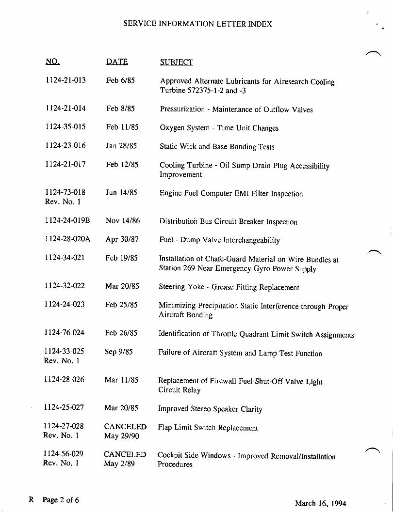
1124-21-013 Feb 6/85 Approved Alternate Lubricants for Airesearch CoolingTurbine 572375-L-2 and -3
1124-21414 Feb 8/85 Pressurization - Maintenance of Outflow Valves
tl24-35-015 Feb I l/85 Oxygen System - Time Unir Changes
1124-23-016 Jan 28/85 Sratic wick and Base Bonding Tesrs
ll24-21-0l7 Feb l2l85 Cooling Turbine - Oil Sump Drain Plug AccessibiliryImprovement
1124-73-018 Jun 14185 Engine Fuel Computer EMI Filter InspectionRev. No. I
1124-24-0198 Nov 14186 Distributioh Bus Circuit Breaker Inspecrion
1124-28-020{ Apr 30/87 Fuel - Dump valve Interchangeability
lL24-34-021 Feb 19/85 Installation of Chafe-Guard Material on Wire Bundles atStation 269 Near Emergency Gyro power Supply
1124-32422 Mar 20185 Steering yoke - Grease Fitting Replacement
1124-24-023 Feb 25185 Minimizing Precipitation Static Interference through properAircraft Bonding
1124-76-024 Feb 26185 Identification of Throttle Quadrant Limit Switch Assignments
1124-33-025 Sep 9/85 Failure of Aircraft System and Lamp Test FunctionRev. No. I
1124-28-026 Mar 11/85 Replacement of Firewall Fuel Shut-Off Valve LightCiicuit Relay
1124-25-027 Mar 20185 Improved stereo speaker clarity
1124-27428 CANCELED Flap Limit switch ReplacemenrRev. No. 1 May 29190
1124-56-029 CANCELED Cockpit Side Windows - Improved Removal/InstallationRev. No. I May 2189 procedures
R Page2 of 6 March 16, 1994
SERVICE INFORMATION LETTER INDEX
NO. DATE SUBJECT
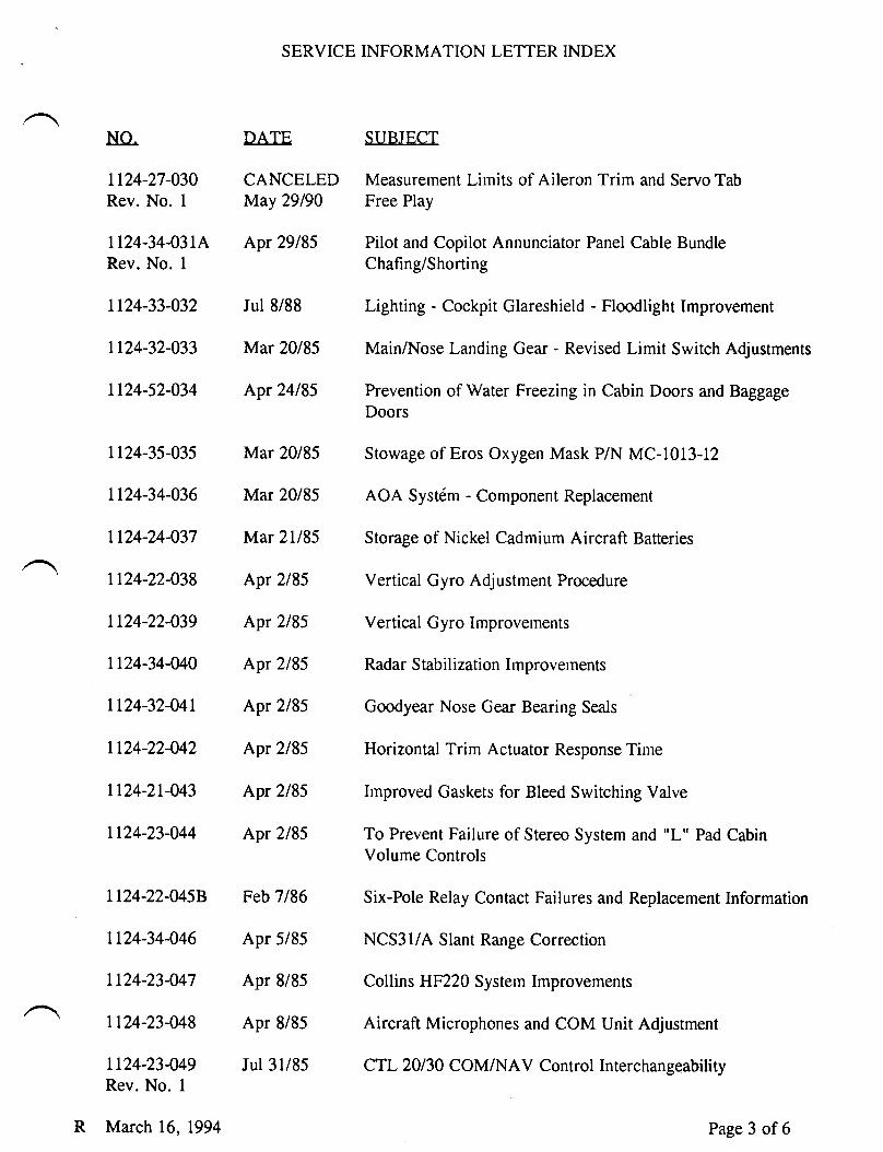
Lt24-27-030 CANCELED Measurement Limits of Aileron Trim and Servo TabRev. No. 1 May 29190 Free Play
1124-34-031{ Apr 29185 Pilot and Copilot Annunciator Panel Cable BundleRev. No. I Chafing/Shorting
Ll24-33-032 Jul 8/88 Lighting - Cockpit Glareshield - Floodlight Improvement
Ll24-32-033 Mar 20185 Main/Nose Landing Gear - Revised Limit Switch Adjustments
1124-52-034 Apr 24185 Prevention of Water Freezing in Cabin Doors and BaggageDoors
1124-35-035 Mar 20185 Stowage of Eros Oxygen Mask P/N MC-1013-12
1124-34-036 Mar 20185 AOA Syst6m - Component Replacement
1124-24-037 Mar 21185 Storage of Nickel Cadmium Aircraft Batteries
1124-22-038 Apr 2185 Vertical Gyro Adjustment Procedure
Ll24-22-039 Apr 2185 Vertical Gyro Improvements
1124-34-040 Apr 2185 Radar Stabilization Improvements
1124-32-041 Apr 2185 Goodyear Nose Gear Bearing Seals
Ll24-22-042 Apr 2185 Horizontal Trim Actuator Response Time
1124-21-043 Apr 2185 lnproved Gaskets for Bleed Switching Valve
1124-23-044 Apr 2/85 To Prevent Failure of Stereo System and "L" Pad CabinVolume Controls
1124-22-0458 Feb 7/86 Six-Pole Relay Contact Failures and Replacement Information
1124-34-046 Apr 5/85 NCS3llA Slant Range Correction
1124-23-047 Apr 8/85 Collins HF220 Sysrem Improvemenrs
1124-23-048 Apr 8/85 Aircraft Microphones and COM Unit Adjustment
1124-23449 Jul 31/85 CTL20130 COM/NAV Control InterchangeabilityRev. No. 1
R March 16, 1994 Page 3 of6
SERVICE INFORMATION LETTER INDEX
NO. DATE SITBJECT
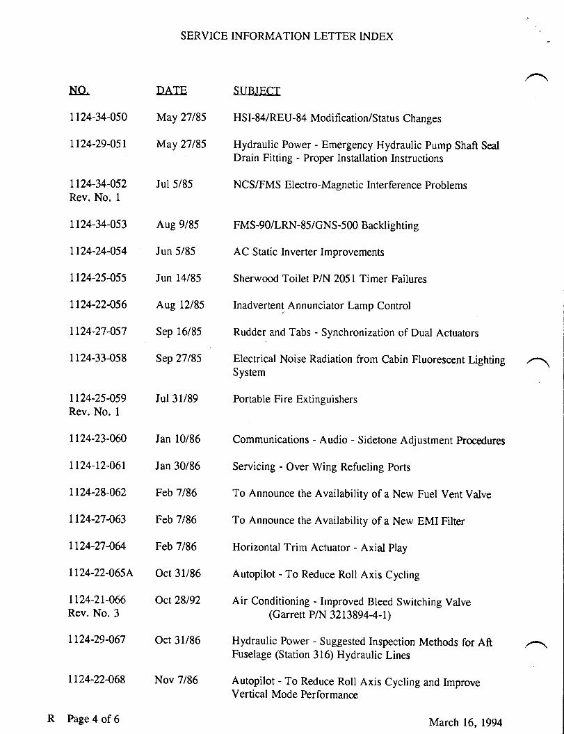
1124-34-050 May 27185 HSI-84/REU-84 Modification/Status Changes
1124-29-051 May 27185 Hydraulic Power - Emergency Hydraulic Pump Shaft SealDrain Fitting - Proper Installation Instructions
1124-34-052 Jul 5/85 NCS/FMS Electro-Magnetic Interference ProblemsRev. No. 1
1124-34-053 Aug 9/85 FMS-90/LRN-85/GNS-500 Backlighting
1124-24-054 Jun 5/85 AC Static Inverter Improvements
tt24-25455 Jun 14185 Sherwood Toilet P/N 2051 Timer Failures
1124-22-056 Aug 12185 Inadvertent Annunciator Lamp Control
1124'27457 Sep 16/85 Rudder and Tabs - Synchronization of Dual Actuators
1124-33-058 Sep 27185 Electrical Noise Radiation from Cabin Fluorescent LightingSystem
1124-25-059 Jul 31/89 Portable Fire ExringuishersRev. No. 1
1124-23-060 Jan 10/86 Communications - Audio - Sidetone Adjustment Procedures
1124-12-061 Jan 30/86 servicing - over wing Refueling porrs
1124-28-062 Feb 7/86 To Announce the Availability of a New Fuel Vent Valve
1124-27-063 Feb 7/86 To Announce the Availability of a New EMI Filter
1124-27-064 Feb 7/86 Horizonral Trim Actuaror - Axial play
1124-22-065{ oct 31/86 Autopilot - To Reduce Roll Axis cycling
1124-21-066 Oct28l92 Air Conditioning - hnproved Bleed Switching ValveRev. No. 3 lGarreff p/N 3213g94-4-t)
1124'29-067 Oct 31/86 Hydraulic Power - Suggested Inspection Methods for AftFuselage (Station 316) Hydraulic Lines
1124-22-068 Nov 7186 Autopilot - To Reduce Roll Axis Cycling and ImproveVertical Mode Performance
R Page 4 of 6 March 16, Lgg4
SERVICE INFORMATION LETTER INDEX
NO. DATF SIIBJECT
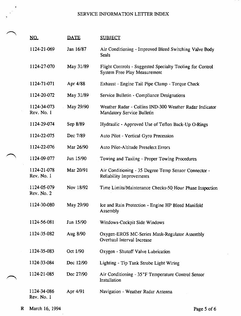
1124-21469 Jan 16187 Air Conditioning - Improved Bleed Switching Valve BodySeals
1124-27470 May 3ll89 Flight Controls - Suggested Specialty Tooling for ControlSystem Free Play Measurement
Ll24-71-071 Apr 4188 Exhaust - Engine Tail Pipe Clamp - Torque Check
1124-20-072 May 31/89 Service Bulletin - Compliance Designations
1124-34-073 May 29190 Weather Radar - Collins IND-300 Weather Radar IndicatorRev. No. I Mandatory Service Bulletin
LL24-29474 Sep 8/89 Hydraulic - Approved Use of Teflon Back-Up O-Rings
1124-22-075 Dec7189 Auto Pilot - Vertical Gyro Precession
1124-22-076 Mar 26/90 Auto Pilot-Altitude Preselect Errors
' 1124-W-077 Jun 15/90 Towing and Taxiing - Proper Towing Procedures
ll24-2l-078 Mar 20191 Air Conditioning - 35 Degree Temp Sensor Connector -Rev. No. 1 Reliability Improvements
112445-079 Nov 18/92 Time Lirnits/Maintenance Checks-50 Hour Phase InspectionRev. No. 2
1124-30-080 May 29190 Ice and Rain Protection - Engine HP Bleed ManifoldAssembly
1124-56-081 Jun 15/90 Windows-Cockpit Side Windows
1124-35-082 Aug 8/90 Oxygen-EROS MC-Series Mask-Regulator AssemblyOverhaul Interval Increase
1124-35-083 Oct 1/90 Oxygen - Shutoff Valve Lubricarion
tl24-33-084 Dec L2/90 Lighting - Tip Tank Strobe Light Wiring
,,.- 1124-21'085 Dec 21190 Air Conditioning - 35"F Temperature Control Sensor' \ Installation
Ll24-34-086 Apr 4l9l Navigation - Weather Radar AnrennaRev. No. I
R March 16,1994 Page 5 of 6
-lSERVICE INFORMATION LETTER INDEX
NO. DATE SUBJECT
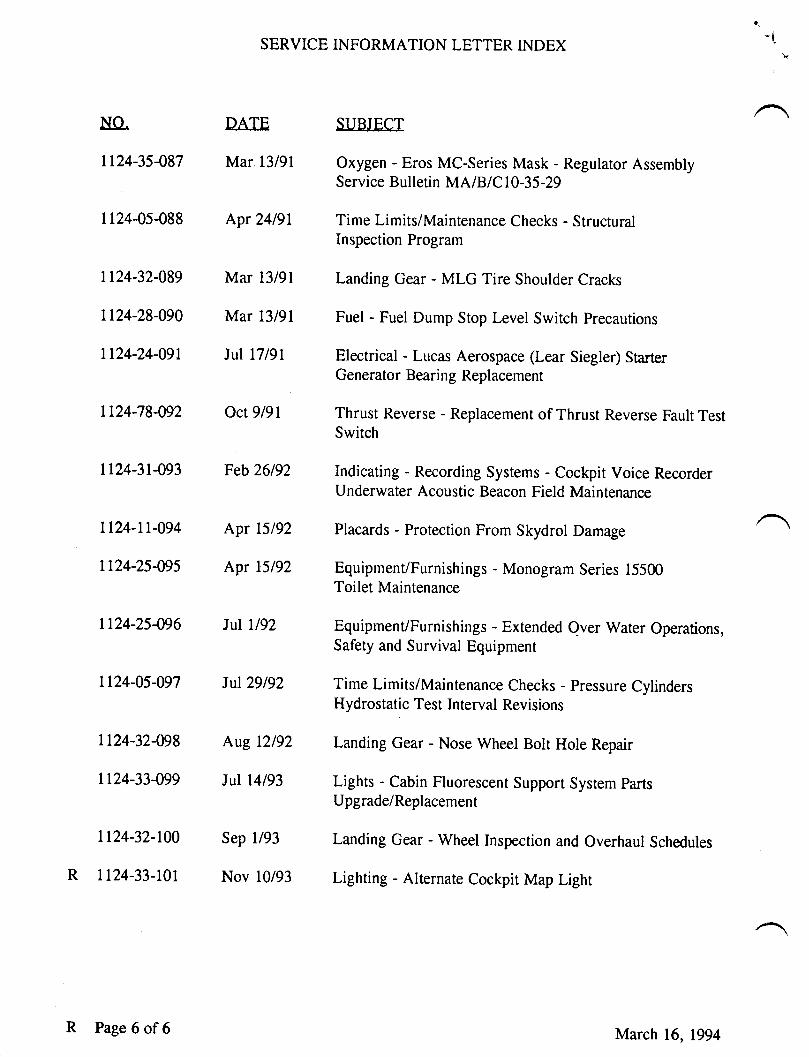
LL24-35487 Mar 13/91 Oxygen - Eros MC-Series Mask - Regulator AssemblyService Bulletin MA/B/C I 0 -35 -29
1124-05-088 Apr 24191 Time Limits/Maintenance Checks - StructuralInspection Program
1124-32-089 Mar 13/91 Landing Gear - MLG Tire Shoulder Cracks
Lt24-28-090 Mar 13/91 Fuel - Fuel Dump Stop Level Switch Precautions
1124-24-091 Jul l7l9L Electrical - Lucas Aerospace (Lear Siegler) SrarterGenerator Bearing Replacement
It24'78-092 Oct 9/91 Thrust Reverse - Replacement of Thrust Reverse Fault TestSwitch
1124-31-093 Feb 26192 Indicating - Recording Systems - Cockpit Voice RecorderUnderwater Acoustic Beacon Field Maintenance
1124-11-094 Apr 15192 Placards - Protection From Skydrol Damage
1124-25-095 Apr 15192 Equipment/Furnishings - Monogram Series 15500Toilet Maintenance
1124-25-096 luI ll92 Equipment/Furnishings - Extended Over Water Operations,Safety and Survival Equipment
1124-05-097 JuI29l92 Time Limits/Maintenance Checks - Pressure CylindersHydrostatic Test Interval Revisions
1124-32-098 Aug 12192 Landing Gear - Nose Wheel Bolt Hole Repair
1124-33-099 Jul 14193 Lights - Cabin Fluorescent Support Sysrem parts
Upgrade/Replacement
1124-32-100 Sep l/93 Landing Gear - Wheel Inspection and Overhaul Schedules
R ll24-33-lol Nov 10193 Lighting - Alternate cockpit Map Lighr
R Page 6 of6 March 16, 1994
IllJ tilIl
SERY'CEINFORMATION LETTER
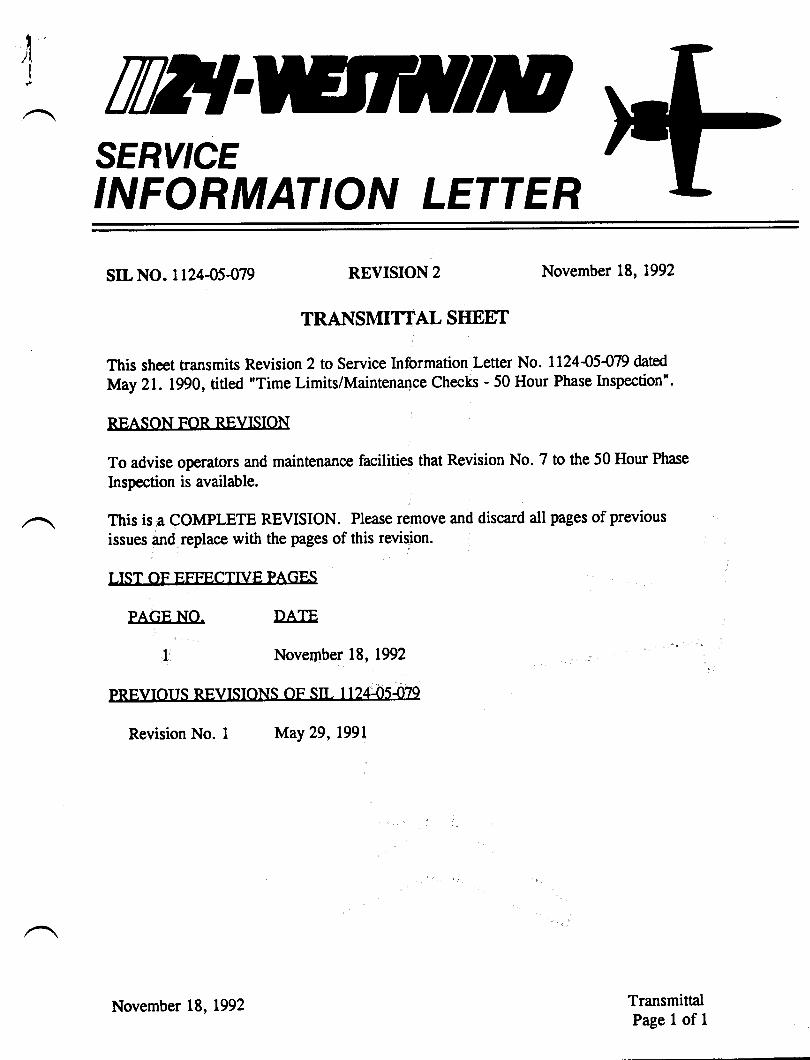
sIL NO. L12445479 REVISION 2
TRANSIVilTTAL SIIEET
November 18, L992
This sheet transmits Revision 2 to Service Information Letter No. 112445479 datfd
May 21. 1990, titled "Time Limits/Maintenance Checks - 50 Hour Phase Inspection".
RFASON FOR RFVISION
To advise operators and maintenance facilities that Revision No. 7 to the 50 Hour Phase
Inspection is available.
This is a COMPLETE REVISION. Please remove and discard all pages of previous
issues and replace with the pages of this revision.
I IST OF FFFFCTTVE PAGBS
PAGF NO. DATF
November 18, t992
PRFVIOIIS RFVTSIONS OF STI I 12445470
Revision No. I May 29, L99l
TransmittalPage I of 1
November L8, L992
-/
, TWTSERY'CEINFORMATION LETTER
srL No. 112445479 May 29,1990
. 50 HOI]R PHASESU&IECT: TIME LIMITS/MAINTENANCE CHECKSINSPECTION
EFFECTIVITY: MODEL 1124 AND LT24A WESTWIND, aII SETiAI NUMbCTS.
A. REASON
To advise operators and maintenance facilities that Revision No. 7 to the 50
Hour Phase Inspection has been issued.
B. REFERENCE
Ll24tlL24A Westwind Maintenance Manual, Chapter 5-10-00 through 5-30-00.
ll24lll24| Westwind Maintenance Manual, Temporary Revision No. 5-6.
PIJBLICATIONS AFFECTED
50 Hour Phase Inspection.
DESCRIPTION
The 50 Hour Phase Inspection has been revised to Revision No. 7. This revision
incorporates ll24l 1124A Westwind Maintenance Manual, Temporary Revision
No. 5-6 into the 50 Hour Phase Inspection Program.
One copy of Revision No. 7 to the 50 Hour Phase Inspection is available to each
current Service Data Book subscriber at no charge. To receive your copy' please
calt Astra Jet Corporation, Technical Publications, 302-324-5t50.
c.
D.
May 21, 1990
Revision 2. November 18. 1992
str- 112445479Pase 1 of 1
TW{SERY'CEINFORMATION LETTER
SER.VICE INFORMATION I,ETTER, NO. 112445488 April 24, L99l
SU&IECT: TIME LIMITS - MAINTENANCE CI{ECKS - STRUCTURALINSPECTION PROGRAM
EFT'ECTIVITY: Model ll24lll24A WESTWINDS, all serial numbers.
A. REASON
To emphasize that it is MANDATORY to comply with the Structural InspectionProgram, Section 540-00 through 54045 of the ll24lLI24A WestwindMaintenance Manual.
B. REFERENCE
ll24lll24| Westwind Maintenance Manual, Chapter 540{0 through 540{5.Nondestructive Testing Manual.Federal Aviation Regulation (FAR) Part 91, Sub Part D (Current Revision).Civil Aviation Administration of Israel, Airworthiness Directive No. 91{1.
C. PUBLICATIONS AFFECTED
NONE
D. DESCRIPTION
This SIL is issued to emphasize that to be in compliance with current FederalAviation Regulation (FAR) Part 91, sub part D, it is MANDATORY to complywith the Structural lnspection Program, Section 5-40-00 through 540-05 of theLl24lIl24A Maintenance Manual at intervals specified therein. The SfructuralInspection Program is also referred to in the General section of the LL24lll24A50 Hour Phase Inspection Program.
April 24, L99t677
srl. 1124-05-088Page 1 of2
SERVICE INFORMATION LETTER NO. 1124{5{88
Inspection of aircraft structure must be done in accordance with ttreNondestructive Testing Manual, at intervals specified in the Structural InspctionProgram.
Aircraft registered in countries other than the United States are advised that theCivil Aviation Administration of Israel has issued an Airworthiness Directive,No. 91{1, dated March 11, 1991, mandating compliance of the structuralInspection Program.
srl- I12445488Page 2 of 2
April 24,1991
TW]SERY'CEINFORMATION LETTER
SERVICE INFORMATION LETTER NO. 1124-05-097 Iuly 29, 1992
SUBJECT:
EFFECTIVITY:
A. REASON
IuIy 29,19925201,
TIME LIMITS/MAINTENANCE CHECKS - PRESSI]RECYLINDERS HYDROSTATIC TEST INTERVAL REVISIONS
MODEL lI24l1,L24A WESTWIND. all serial numbers.
To announce revisions to pressure cylinders hydrostatic test intervals.
B. REFERENCE
I t24 I I l24A Westwind Maintenance Manual, Chapter 5- 1 0-00.Federal Aviation Administration Order 8000.40C.
C. PUBLICATIONSAFFECTED
lI24 I ll24A Westwind Maintenance Manual, Chapter 5- 1 0-00.
D. DESCRIPTION
The Federal Aviation Administration has issued FAA Order 8000.40C addressing"Maintenance of pressure cylinders in use as aircraft equipment." Previously, itwas permissible to leave a pressurized container in service past its hydrostatic testdate, provided there was no visible damage and it was properly charged.According to this FAA Order, 8000.40C, "pressure cylinders used as aircraftequipment may no longer remain in service beyond their hydrostatic test date,regardless of the state of charge of the cylinder."
Effective immediately, compliance of hydrostatic testing of pressure cylindersshall be as follows:
(1) Fire Extinguisher Containers.
(a) For containers last hydrostatic tested before IuIy 29,1988, containers are
due hydrostatic test before July 29, 1993.
sL 1124-05-097Page I of 2
SERVICE INFORMATION LETTER NO. 112445-ry7
(b) For containers last hydrostatic tested after July 29,1988, containers are
due hydrostatic test at five (5) years.
(2) Gas Storage Cylinder @mergency Gear Down and Thrust Reverser).
(a) For cylinders last hydrostatic tested before I:uIy 29,1990, cylinders aredue hydrostatic test before Iily 29,1993.
(b) For cylinders last hydrostatic tested after July 29,1990, cylinders are duehydrostatic test at three (3) years.
A revision to the ll24llI24A Westwind Maintenance Manual, Chapter 5-10{0,with these changes, has been issued.
srl- 1124-05-097Page 2 of 2
Iuly 29, 1992
n2{SERY'CEINFORMATION LETTER
SERVICE INT'ORMATION LETTER NO. 1124-09-W7 June 15, 1990
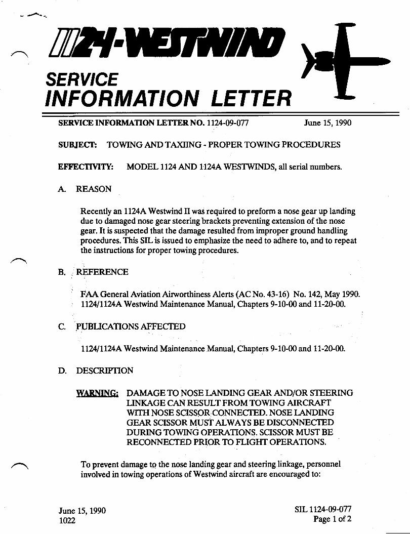
SUBJECT: TOWING AIID TA)ilING - PROPER TOWING PROCEDURES
EFFECTTVIIY: MODEL 1124 AND IIUAWEST\ryINDS, all serial numbers.
A REASON
Recently anlL24AWestrrind II was required to preform a nose gear up landingdue to damaged nose gear steering brackets preventing extension of the nosegear. It is suspected that the damage resulted from improper ground handlingprocedures. This SILis issued to emphasizetbe need to adhere to, and to repeatthe instructions for proper towing procedures.
B. REFERENCE
FAA General Aviation Airworthiness Alerts (AC No. 43-L6) No. 142, May 1990.
ll%l Ll?l[Westrvind Maintenance Manual, Chapters 9- t0-00 and 1 1-20-00.
C. PUBLICATIONSAITECTED
llZ4t Ll24 AWestrvind Maintenance Manual, Chapters 9- 10-00 and 1 1-20-00.
D. DESCRIPTION
IVARNING: DAMAGE TO NOSE I-ANDING GEAR AND/OR STEERINGLINKAGE CAN RESULT FROM TOWING AIRCRAFTWITII NOSE SCISSOR CONNECTED. NOSE I-ANDINGGEAR SCISSOR MUSTALWAYS BE DISCONNECTEDDURING TOWING OPERATIONS. SCISSOR MUST BERECONNECTED PRIOR TO FLIGI{T OPERATIONS.
To prevent damage to the nose landing gear and steering linkage, personnelinvolved in towing operations of Westrvind aircraft are encouraged to:
June 15,1990Lmz
sIL 1124-09-077Page I of 2
SERVICE INFORMATION LETTER NO. 1124-09-077
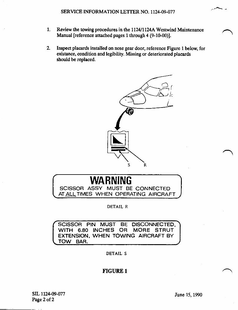
Review the towing procedures in the Ll24lll24lWestrvind MaintenanceManual [reference attached pages 1 through 4 (9-1G00)].
Inspect placards installed on nose gear door, reference Figure 1 below, forexistance, condition and legibility. Missing or deteriorated placardsshould be replaced.
WARNINGSCISSOR ASSY MUST BE CONNECTEDAT ALL TIMES WHEN OPERATING ATBCRAFT
DETAIL R
SCISSOR PIN MUST BE DISCONNECTED.WITH 6.80 INCHES OR MORE STRUTEXTENSION, WHEN TOWING AIRCRAFT BYTOW BAR.
DETAIL S
srLrru-w-w7Page2of 2
tr---=t
FIGURE T
June 15, 1990
r \r]
mnHfllpISRAIT AIRCRAf T INDUSTRITS tIO
MAINTENAI\ICEMANUAL
TOWTNG - DESCRIPTION/OPERATION
R l. General
R A. Towing the aircraft over hard, flat surfaces is accomplished at theR nose gear for normaL naintenance and ramp functions.
R B. I{tren the aircraft has left a hard, flat surface runway and hasR becme nired in soft sand, mud or snolr, the aircraft must be towedR aft from the main gears. Ttre nose gear tow bar should be used onlyR for eteering while the aircraft is being towed.
R C. Provision is nade on the nose gear for attaching a tow barR (P/N 5753517) for towing and pushing the aircraft either by hand orR with a towing vehicle.
R NOTE: Ttre tow bar is standard iseue and must be carried aboard theR aircraft at all times. If tow bar is removed fron theR storage'placed on aircraft, its weight must be subtractedR from baeic operating weight.
R 2. Towing (See Figure 1)
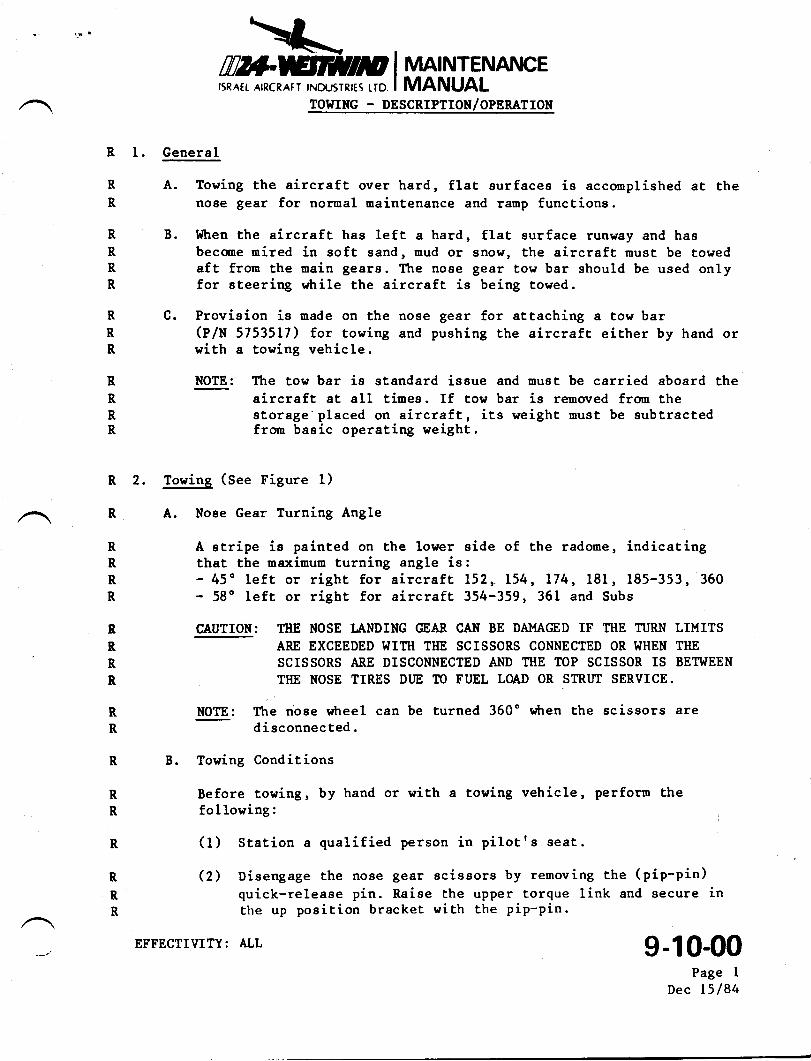
R A. Nose Gear Turning Angle
R A stripe is painted on the lower eide of the radome, indicatingR that the maximum turning angle is:R - 45o left or right for aircraf,t I52,. 154, L74, 181, 185-353, 360R - 58o left or righE for aircraf.t 354-359, 361 and Subs
B IAUTIONt TIIE NOSE LANDING GEAR CAN BE DAMAGED IF I'IIE TURN LIMITSR ARE EXCEEDED WITH THE SCISSORS CONNECTED OR I{HEN TIIER SCISSORS ARE DISCONNECTED AND TIIE TOP SCISSOR IS BETIilEEN
R TIIE NOSE TIRES DIJE TO FUEL LOAD OR STRUT SERVICE.
R Wr Ttre nose wtreel can be turned 360" wtren Lhe scissors areR disconnected.
R B. Towing Conditions
R Before towing, by hand or with a towing vehicle, perform theR following:
R (1) Station a qualified person in pilotfs seat.
R Q) Disengage the nose gear eciseors by removing the (pip-pin)quick-releaae pin. Raise the upper torque link and aecure inthe up poaition bracket with the pip-pin.
R
R
g-10-00Page I
Dec l5l84
EFFECTIVITY: ALL
\:,I#Bin p i rtnar rurENAr\tcErsR^rr ATRcRATT tNcusTRrrs rro I MANUAL
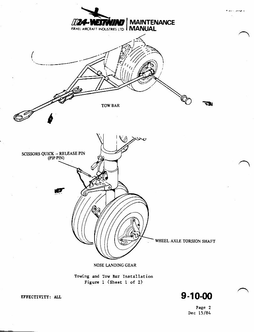
TOW BAR
:VSCISSORS QUICK _ RELEASE PIN
(PIP PIN)
NOSE I..A,NDING GEAR
Towing and Tow Bar InetallationFigure I (Sheet I of 2)
g
=jU
WHEEL AXLE TORSION SHAFT
9-10-00Page 2
Dec 15/84
EFFECTIIIITY: ALL
-E
mrfr.HrtlpISRATt AIRCRAFT INOUSTRITS I.ID
MAINTENANCEMANUAL
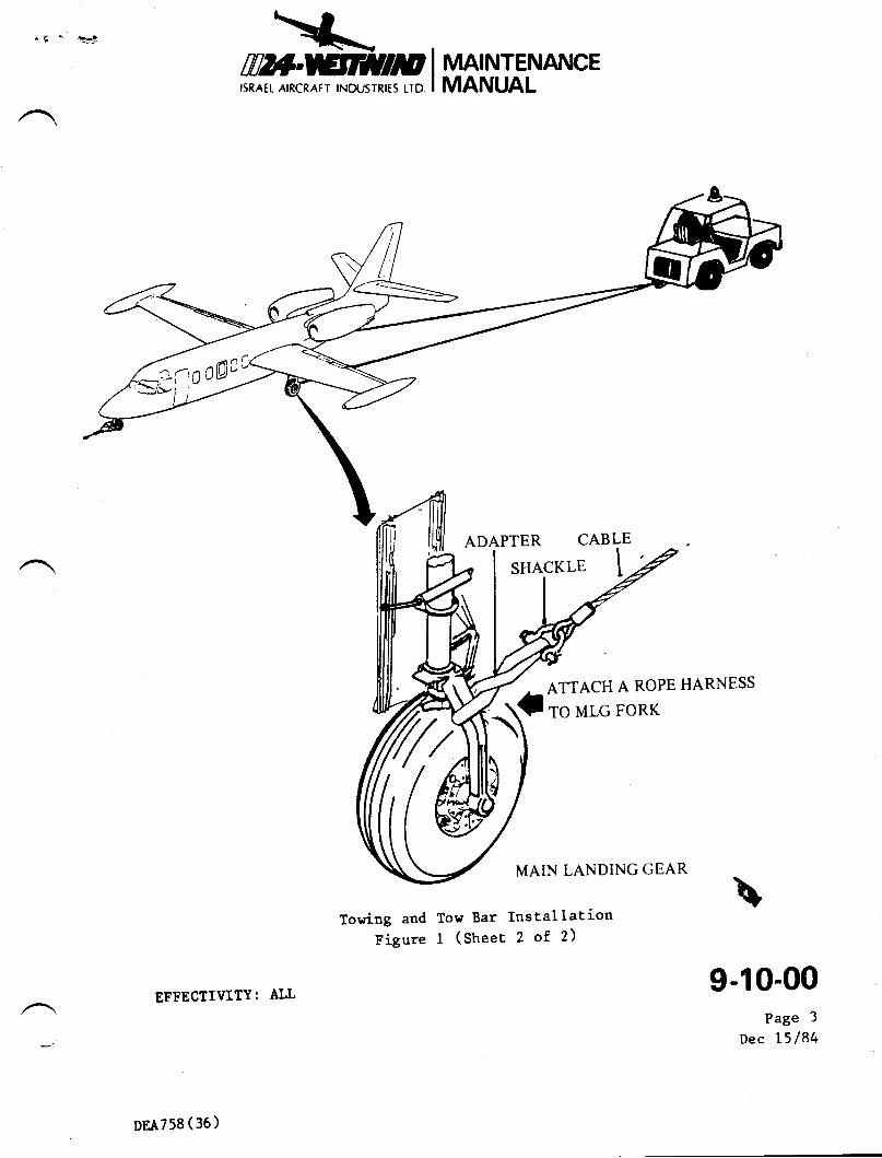
ADAPTER CABLE
SHACKLE T
ATTACH A ROPE HARNESS
TO MLG FORK
MAIN LANDING GEAR
Towing and Tow Bar InstallationFigure I (street 2 of 2)
EFFECTIVITY: ALL9-10-00
Page 3
Dec l5l84
'/- atnl,:zfto0A":
DEA758 ( 36 )
\-,=h_\---rffi?nHEinm I MA|NTENANCE
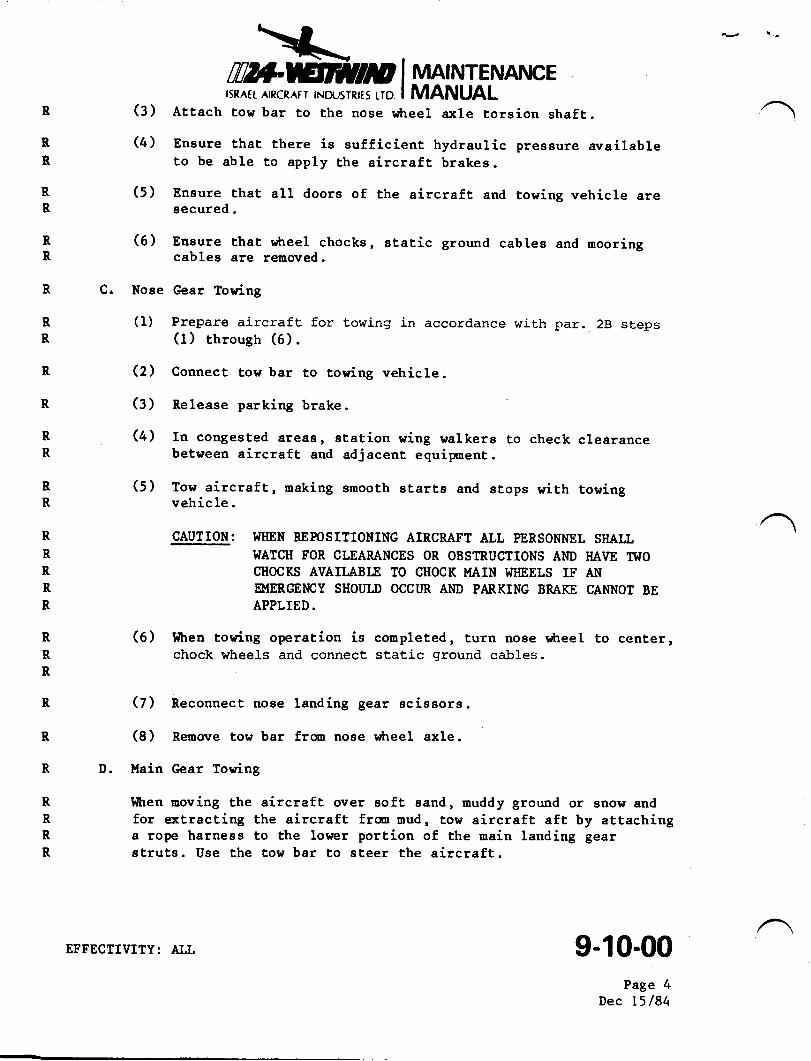
I5RATI. AIRCRAIT INOIJ5TRITS LID I MANUALR (3) Attach tow bar to the nose rdtreel a:<1e torsion ehaft.
R (4) Ensure that there is eufficient hydraulic presgure availableR to be able to apply the aircraft brakes.
R (5) Eneure that all doors of the aircraft and towing vehicle areR secured.
R (6) Ensure that r*reel chocks, static ground cables and nooringR cables are removed.
R C. Nose Gear Towing
R (1) Prepare aircraft for towing in accordance with par. 28 stepsR (1) through (6).
R (2) Connect tow bar to towing vehicle.
R (3) Release parking brake
R (4) In congested areas, station wing walkers to check clearanceR between aircraft and adjacent equipnent.
R (5) Tow aircraft, naking smooth starte and stops with towingR vehicle.
R CAUTION: WIIEN REPOSITIONING AIRCRAFT ALL PERSONNEL SHALLR I{ATCH FOR CLEARANCES OR OBSTRUCTIONS AIID HAVE II{OR CHOCKS AVAII.ABTE TO CIIOCK MAIN I.IIIEELS IF ANR EMERGEI{CY SHOIILD OCCUR AI{D PARKING BRAKE CANNOT BER APPLIED.
R (6) I'ltren towing operation is completed, turn noee L'heel to center,R chock wheels and connect static ground cables.R
R (7) Reconnect noee landing gear scissors.
R (8 ) Remorre tow bar from nose wtreel axle .
R D. Main C;ear Towing
R l{tren moving the aircraft over soft Band, muddy ground or snow andR for extracting the aircraft frm mud, tow aircraft aft by attachingR a rope harnees to the lower portion of the main landing gearR struts. Use the tow bar to steer the aircraft.
4- l.
9-10-00Page 4
Dec l5l84
EFFECTIVITY: ALL
TWTSERY'CEINFORMATION LETTER
srr, No. I124-12-06I
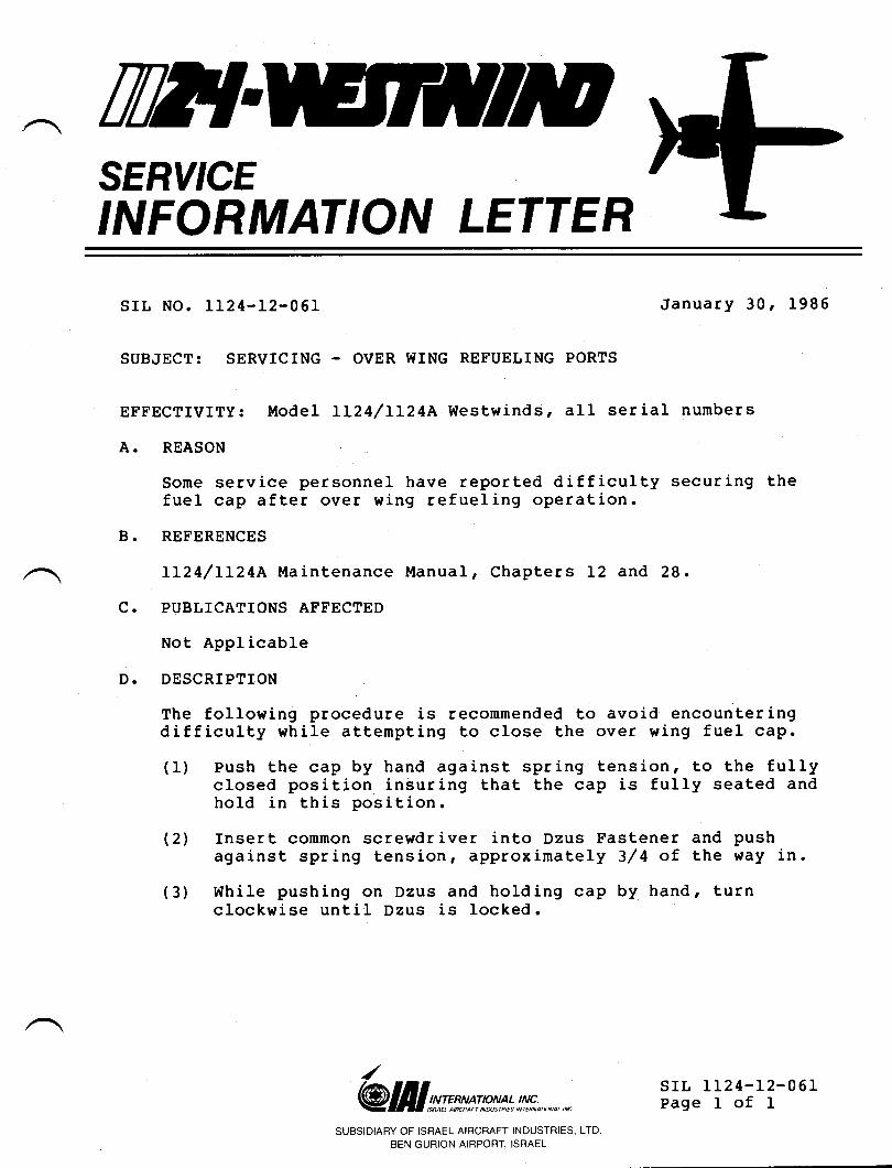
SUBJECT: SERVICING - OVER WING REFUELING PORTS
January 30 r 1985
EI'FECTIVITY: ModeI LL24lLL24A Westwinds, all serial numbers
A. REASON
Some service personnel have reported difficulty securing thefuel cap after over wing refueling operation.
B. REFERENCES
LL24/LL24A Maintenance llanual, Chapters L2 and 28.
PUBLICATIONS AFFECTED
Not Applicable
DESCRIPTION
The following procedure is recommended to avoid encounteringdifficulty while attempting to close the over wing fuel caP.
(1) Push the cap by hand against spring tension' to the fullyclosed position insuring that the cap is fully seated andhold in this position.
(21 Insert conmon screwdriver into Dzus Fastener and pushaga inst spr ing tens ion , approx imately 3/ 4 of the ',{ay in .
(3) While pushing on Dzus and holding cap by hand, turnclockwise until Dzus is locked.
c.
D.
/
@ lI I st:n*s !p*t* l!Y;, ^.,, *SUBSIDIARY OF ISRAEL AIRCRAFT INDUSTRIES, LTD
BEN GURION AIRPORT, ISRAEL
srL 1124-12-06rPage I of I
IWTSERY'CEINFORMATION LETTER
A.
B.
c.
D.
SERVICE INTORMATION LETTER NO. 1124-20-072 May 31, 1989
SUBJECT: SERVICE BULLETIN COMPLIANCE DESIGNATIONS
EFFECTMTY: MODET 112411124 l{estwind, alI serial numbers
REASON
To introduce a nevr ||I'{ANDATORY" compliance designation anddefine all the compliance designations.
REFERENCE
None.
PUBLICATION AFFECTED
Service bulletins as deemed necessary.
DESCRIPTION
Service bulletins will now have one of the three followingcompliance designations :
OPTIONAL
The "optional" category indicates that implementation of theservice bulletin is at the discretion of the user.
The "OptionaI" category is used for modifications which someusers, may not need or benefit from. However, themodification is stiIl considered an improvement for theaffected aircraft.
@ III srme** !,!!u';n *.,, *SUBSIDIARY OF ISRAEL AIRCRAFT INDUSTRIES, LTD.
BEN GURIoN AtRPoRr, ISRAEL SIL 1124-24-072Pase 1 of 2
/
SERVICE INFORMATION LETTER 1124-20-072
RECOMI{ENDED
The "Recommended" category indicates that all users ofaffected aircraft should implement the service bulletin attheir earliest convenience-
The "Recommended" category is used to improve operatlonof the affected aircraft.
MANDATORY
The "Mandatory" category indicatesaffected type and S/N are urged tofor compliance is included.
that all aircraft ofcomply. A period or date
The "Mandatory'r category is used when rAr assesses thatcompliance is essential to meet desired reliability,maintenance or performance design criteria of the aircraft.All registered owners of affected aircraft will be notifiedof the existence, reason for, availability, and complianceinstructions of a "Mandatoryrt service bulletin.The FAA considers a service bulretin to be mandatory basedon the following criteria:1 - service bulletins listed in the Type certificate Data
Sheet
2 service bulletins referenced in AD notes
3 - inspection in accordance with a service bulretin ifit is listed in the inspection program as required byFAR 91 .1 69
unless a service bulletin comes under these criteriar dnoperator is not obligated to accomplish it, even if it isdesignated as Mandatory. No manufacturer can mandatecompliance.
srl, 1124-20-072Page 2 of 2
May 31, 1 989
til?lSERY'CEINFORMATION LETTER
SMVICE INFORMATION LETTER, NO. I 124-20-102 April 6,1994
SU&IECT: STANDARD PRACTICES - AIRWORTHINESS OF PARTS
EFFECTIVITY: MODEL ll24 & ll24| WRSTWIND, all serial numbers.
A. REASON
Throughout the industry there is a growing conoern over unapproved parts
being installed on aircraft. The Federal Aviation Administration (FAA) places
the responsibility on the person installing parts to determine the airworthiness
of a part. The installer then assumes liability for the airworthiness of the partinstalled, which is particularly onerous if the aircraft is involved in an accident
or incident.
Astra Jet Corporation (AJC) recognizes the difficulty an installer may have indetermining a particular part's airworthiness, and to assist the installer, we have
prepared this Service Information Letter (SfL).
B. REFERENCE
Code of Federat Regualations (CFR) Title 14
C. PUBLICATIONSAFFECTED
None
D. DESCRIPTION
AJC certifies that all parts in our inventory have been obtained from IsraelAircraft Industry QAI) or IAI's approved sources and have been accepted
under IAI's Civil Aviation Administration of Israel (CAAD or AJC's FAAapproved inspection system. All parts are traceable through IAI/AJC purchase
orders and shipping documents.
April 6,19945288
sII- 1t24-20-102Page I of4
SERVICE INFORMATION LETTER NO. I124-20-102
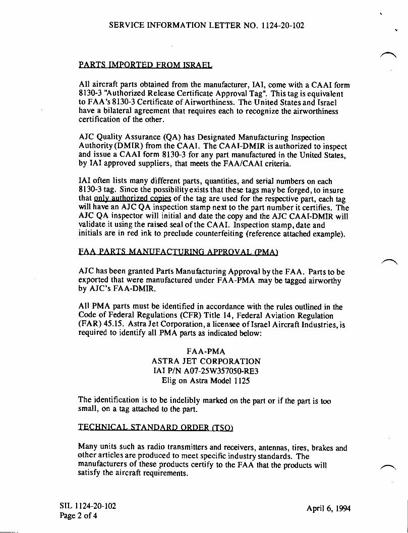
PARTS IMPORTFN FROM TSRAFI
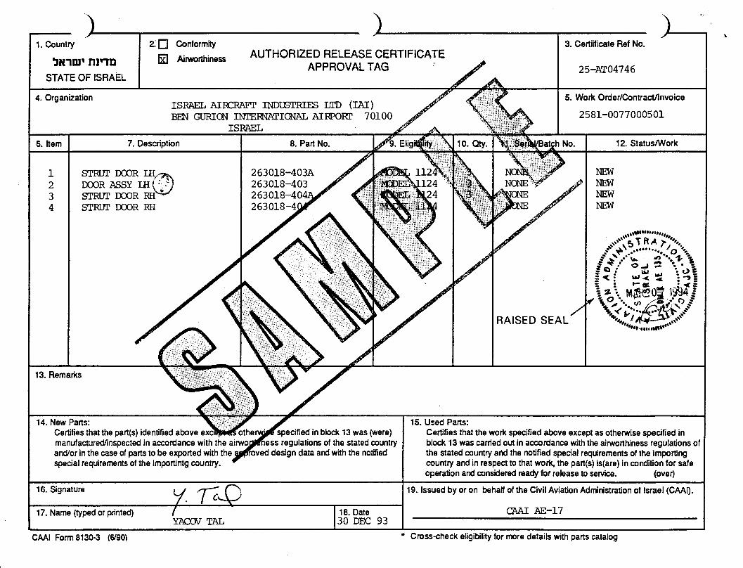
All aircraft parts obtained from the manufacturer, IAI, come with a CAAI form8130-3 'Authorized Release Certificate Approval Tag". This tag is equivalentto FAA's 8130-3 Certificate of Airworthiness. The United States and Israelhave a bilateral agreement that requires each to recognizethe airworthinesscertification of the other.
AJC Quality Assurance (QA) has Designated Manufacturing InspectionAuthority (DMIR) from the CAAI. The CAAI-DMIR is authorized to inspectand issue a CAAI form 8130-3 for any part manufactured in the United States,by IAI approved suppliers, that meets the FAA/CAAI criteria.
IAI often lists many different parts, quantities, and serial numbers on each8130-3 tag. Since the possibilityexists that these tags maybe forged, to insurethat only authorized copies of the tag are used for the respective part, each tagwill have an AJC QA inspection stamp next to the part number it certifies. TheAIC QA inspector will initial and date the copy and the AJC CAAI-DMIR willvalidate it using the raised seal of the CAAI. Inspection stamp, date andinitials are in red ink to preclude counterfeiting (reference attached example).
FAA PARTS MANUFACTTIRING APPROVAT (PMA)
AJC has been granted Parts Manufacturing Approral by the FAA. Parts to begxportgd that were manufactured under FAA-PMA may be tagged airworthyby AJC's FAA-DMIR.
All PMA parts must be identified in accordance with the rules outlined in theCode of Federal Regulations (CFR) Title 14, Federal Aviation Regulation(FAR) 45.15. Astra Jet Corporation, a licensee of Israel Aircraft Industries, isrequired to identify all PMA parts as indicated below:
FAA-PMAASTRA JET CORPORATIONrAr P/N A07-25W357050-RE3
Elig on Astra Model 1125
The identification is to be indelibly marked on the part or if the part is toosmall, on a tag attached to the part.
TECHNTCAL STANnARD ORDER (TSO)
Many units such as radio transmitters and receivers, antennas, tires, brakes andother articles are produced to meet specific industry standards. Themanufacturers of these products certify to the FAA that the products willsatisfy the aircraft requirements.
srr. 1124-20-102Page2 of 4
April 6,1994
SERVICE INFORMATION LETTER NO. 1124-20-102
Manufacturers will identify their product as TSO and indicate the classification
under which the unit was certified, i.e., high frequency radio transmittingequipment may be produced under TSO-C31b whereas high frequency radioreceiving equipment would be under TSO-C32b.
There is a standard method of product identification. CFR 14, FAR 21.ffi7requires that a TSO part be permanently and legibly marked as shown below inthe following example:
ANTENNA, GLIDE SLOPE, DGI P/N RGS 1048
FAA TSO C34C
DAYTON-GRANGER, INC FT. LAUDERDALE, FL
Anyunit identified in this manner maybe accepted as airworthy. An FAA8130-3 tag or its equivalent CAA tag is required for export.
STANnARD HARnWARE / OUAI IFIFn PROnIICT LrST (OPI )
There are a number of standards in use today. These include, but are notlimited to, MIL specs, AN, MS and NAS specifications for hardware. Variousgovernment agencies may approve manufacturers to produce one or moreparts to these drawings. The manufacturers and their distributors may thenhave their names entered on a Qualified Products List (QPL) which iscontrolled by the Department of Defense along with the distributors of these
products.
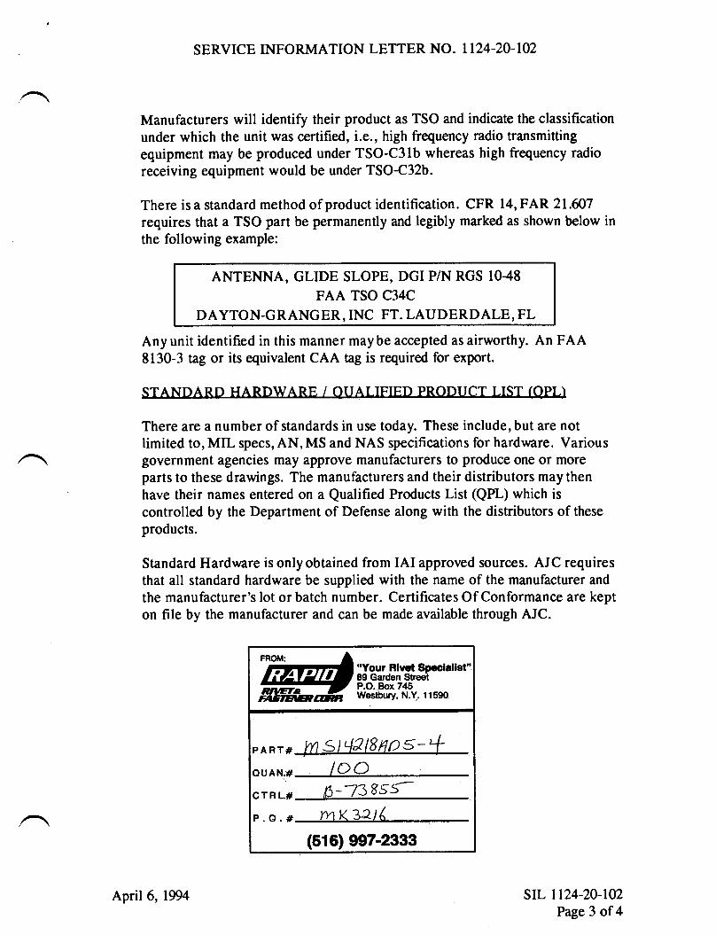
Standard Hardware is only obtained from IAI approved sources. AJC requiresthat all standard hardware be supplied with the name of the manufacturer and
the manufacturer's lot or batch number. Certificates Of Conformance are kepton file by the manufacturer and can be made available through AJC.
"Your Rlvel89 GardenP.O. Box 745Wetbury, N.Y. 11590
PART#
OUAN.#
CTRL#
P.O.#
b-a38ss-rn K 32t(
(516) 9e7-2333
loo
sII- r r24-20-t02Page 3 of4
April 6,1994
SERVICE INFORMATION LETTER NO. 1124-20-102
FA { RFPATR STATION
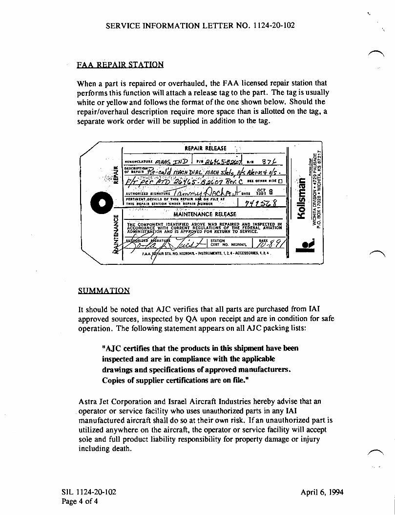
When a part is repaired or overhauled, the FAA licensed repair station thatperforms this function will attach a release tag to the part. The tag is usuallywhite or lellow and follows the format of the one shown below. Should therepair/overhaul description require more space than is allotted on the tlg, a
separate work order will be supplied in addition to the tag.
SUMMATTON
It should be noted that AJC verifies that all parts are purchased from IAIapproved sources, inspected by QA upon receipt and are in condition for safe
operation. The following statement appears on all AJC packing lists:
'AJC certifies that the products in this shiprnent have been
inspected and arc in compliance with the applicable
drawings and specilications of approved manufacturers.Copies of supplier certifications ane on file."
Astra Jet Corporation and Israel Aircraft Industries hereby advise that an
operator or service facility who uses unauthorized parts in any IAImanufactured aircraft shall do so at their own risk. If an unauthorized part isutilized anywhere on the aircraft, the operator or service facility will accept
sole and full product liability responsibility for property damage or injuryincluding death.
srr- 1124-20-102Page 4 of4
April 6,1994
ct!I.!(t(,t,Et!C
LE!Pa!o!toEo.o'6,o!(,oE
.ooU'
ooa
UJ
F...
oE(r!uo{J<uJ l-A
Jul>JOurErL o-/^r o-tr<NEoIFl
8bgF
Etr€98ftrtsc*i
6(Do(ito(r,
@EEoIL()
JgHE
6tr;ao
b Fp
5 Ffr
-
I
4Atr
f H
33=
H;
Esi
5Ein
;EE
glt I
€ gE
e E
3 n
ire
$ *=
Eg
g4 3
5s*
i H;e
a gr
7 n
st*
*siE
;i llH
gFil
1$is
ss
sdE
:sq
qs +
i gX
il;t
tiil i
flili
qa ?
\ffi
;lo=
1.
T*.
=+
F id
isE
E ;i
lnq;
3 gg
ei *i
g 3
8'H
= g
q:,Q
H;-
=
rT
iin sr
;-E
sg
= o
=A
B E
iee.
=a
Et
qa E
d;i 7
:F E
3E=
=
:9.
=o
-a
TW{SERY'CEINFORMATION LETTER
SM.VICE INFORMATION LETTER NO. 1 T24-20-IO4 July 20,1994
SUBIECT: STANDARD PRACTICES - AIRFIELD CRASH CREWINFORMATION
EFFECTIVITY: MODEL ll24llI24A WESTWIND, all serial numbers.
A. REASON
To provide airfield emergency services units with information prevalent to the
model |l24l ll24A Westwind.
B. REFERENCE
None.
C. PUBLICATIONS AFFECTED
None.
D. DESCRIPTION
Please provide copies of the attached airfield crash crew information to the
airfield emergency services units located at the airfield at which you are based
and airfields you frequently visit. Additional copies of this SIL are availablefrom Astra Jet Corporation, Technical Publications Department.
July 20, 1994
5257
srl- 1124-20-104Page I of I
:
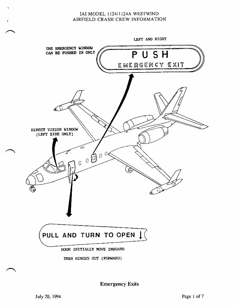
IAI MODEL TT24II124A WESTWINDAIRFIELD CRASH CREW INFORMATION
LEFT Al,lD RIGIfT
TTIE EITIERGENCY IJINDOId
CN{ BE PUSHED IN ONLY
DIRECT VISION WINDOT.J
(LErr srDE ONLY)
DOOR INITIALLY MOVE INBOARD
THEN HTNGES OUT (FORWAnD)
luly 20,1994
Emergency Exits
Page I of7
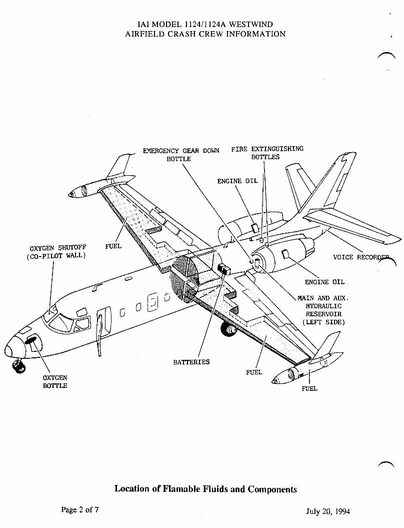
IAI MODEL II24III24A WESTWINDAIRFIELD CRASH CREW INFORMATION
EI'IERCENCY GEAR DOWN
BOTTLE
FIRE D(TINGUISHINCBOTTLES
ENGINE OIL
OXYGEN SHUTOFF
(co-PrLoT WALL)
FUEL
BATTERIES
vorcE REcoRPq\
ENCINE OIL
MAIN AND AUX.HTDRAULICRESERVOIR
(LEFr SrDE)
Page2 of 7
Location of Flamable Fluids and Components
Iuly 20,1994
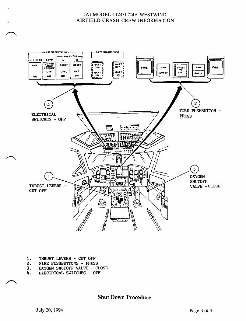
IAI MODEL T124III24AAIRFIELD CRASH CREW
WESTWINDINFORMATION
r-EXT tOW€n
HffiHHtffilli ::: illl oN rl @H@ffi@
MASTEFSWIICHES_t-cENEBATOi -llBAYTtLtI-
rr^tt DrscoNN€crl
ELECTRICALSWITCHES . OFF
FIRE PUSHBUTTON
PRESS
1.2.3.4.
THRUST LEIY-ERS . CUT OFFFIRE PUSHBUTTONS - PRESS
OXYGEN SHUTOFF VALI'E - CLOSEELECTRICAL SWITCHES . OFF
OXYGEN
SHUTOFFVALVE -CLOSE
Z[\\:
Iuly 20,1994
Shut Down Procedure
Page 3 of7
IAI MODEL II24I1124A WESTWINDAIRFIELD CRASH CREW INFORMATION
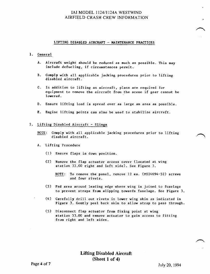
LIFTINC DISABLED AIRCRAFT - I.IAINTENANCE PRACTICES
l. General
A. Aircraft weight should be reduced as much as possible. This mayinclude defueling, if circumstancea perurit.
B. Conply with alL applicable jacking procedures prior to liftingdisabled aircraft.
C. In addition to lifting an aircraft, plans are required forequiprnent to remove the aircraft from the scene if gear cannot belowered.
D. Ensure lifting load is spread over as large an area as possible.
E. Engine lifting points can also be used to stabilize aircraft.
2, Lifting Disabled Aircraft - Slings
NOTE: Coruply L'ith all applicable jacking procedures prior to lifting .a.disabled aircraft \
A. Lifting Procedure
(1) Ensure flaps in dorm position.
Q) Remove the flap actuator access cover (located at wingstation 33.00 right and left side). See Figure 3.
NOTE: To remove the panel, remove 12 ea. (MS24694-52) screwsand four rivets.
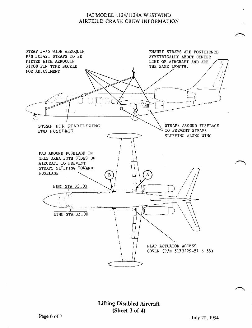
(3) Pad area around leading edge where wing is joined to fuselageto prevent straps frm slipping towards fuselage. See Figure 3.
(4) Carefully drill out rivets in loyer wing skin as indicated inFigure 3. Gently peel back skin to allow strap to pass through.
(5) Disconnect flap actuator fron fixing point at wingstation 33.00 and rernove actuator to gain access to fittingfron right and left sides.
Lifting Disabled Aircraft(Sheet 1 of 4)
Page 4 of 7 Iuly 20,1994
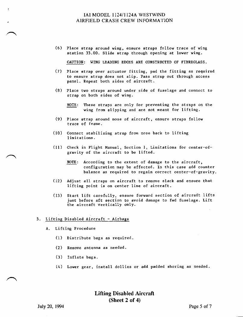
IAI MODEL II24/II24A WESTWINDAIRFIELD CRASH CREW INFORMATION
(6) Place strap around wing, ensure straps follow trace of wingstation 33.00. Slide strap through opening at lower wing.
CAUTION: WING LEADING EDGES ARE CONSTRUCTED OF FIBREGLASS.
(7) Place strap over actuator fitting, pad the fitting as requiredto ensure strap does not slip. Pass strap out through accesspanel. Repeat both sides of aircraft.
(8) Place two straps around under side of fuselage and connect tostrap on both sides of wing.
NOTE: These straps are only for preventing the straps on thewing fron slipping and are not meant for lifting.
(9) Place strap around nose of aircraft, ensure straps followtrace of frame.
(10) Connect stabilizing strap from nose back to liftinglimitations.
(11) Check in Flight Manual, Section l, Limitations for center-of-gravity of the aircraft to be lifted.
NOTE: According to the extent of damage to the aircraft,configuration may be affected. In this case add counterbalance as required to regain correct center-of-gravity.
(12) AdjusE all straps on aircraft to remove slack and ensure Ehatlifting point is on center line of aircraft.
(13) Start lift carefully, ensure forward section of aircraft liftsjust before aft section to avoid damage to fwd fuselage. Liftthe aircraft vertically on1y.
3. Lifting Disabled Aircraft - Airbags
A. Lifting Procedure
(1) Distribute bags as required.
(2) Remove antenna as needed.
(3) Inflate bags.
(4) Lower gear, inetall dollies or add padded shoring as needed.
Lifting Disabled Aircraft
July 20, 1994
(Sheet 2 of 4)Page 5 of7
IAI MODEL II24II124A WESTWINDAIRFTELD CRASH CREW INFORMATION
STMP 1-75 WrDE AEROQUTP
P/N 30142. STR^e,pS TO BE
FTTTED lntH AEROQUTP
31008 PIN IYPE BUCKLEFOR ADJUSTMENT
ENSURE STRAPS ARE POSITIONEDSN'{ETRICALLY ABOUT CENTER
STRAPS AROi]ND FUSELAGETO PREVENT STMPSSLIPPING ALONG WING
FLAP ACTUATOR ACCESS
covER (P/N 5173229-57 & 58)
STRAP FOR STABILIZINGFWD FUSELAGE
PAD AROI]ND FUSELAGE INTI1IS AREA BOTH SIDES OF
AIRCRAFT TO PREVNTSTRAPS SLIPPING TOWARD
FUSELAGE
WING STA 33.00
I^IING STA 33 . OO
Lifting Disabled Aircraft(Sheet 3 of 4)
LINE OF AIRCRAFT AND ARETHE SAME LENGTH.
Page 6 of 7 Iuly 20,1994
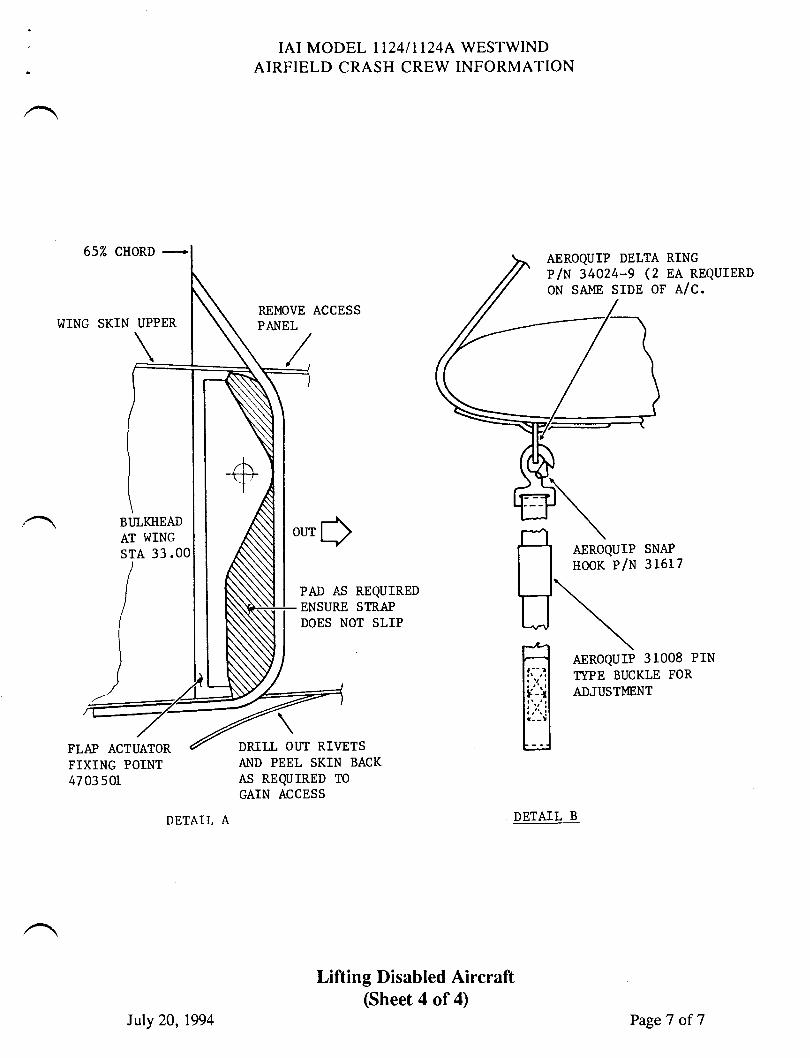
652 CHORD +
WING SKIN UPPER
FLAP ACTUATORFIXING POINT47 03 501
IAI MODEL II24III24A WESTWINDAIRFIELD CRASH CREW INFORMATION
REMOVE ACCESSPA}IEL
PAD IS REQUIREDENSURE STRAPDOES NOT SLIP
RINGEA REQUIERDAlc.
DETAIL A
Lifting Disabled Aircraft(Sheet 4 of 4)
AEROQUIP SNAP
noor p/u 316L7
AEROQUTP 31008 PrNIYPE BUCKLE FOR
ADJUSTMENT
DRTLL OUT RIVETSAND PEEL SKIN BACK
AS REQUIRED TO
GAIN ACCESS
DETAIL B
AEROQUIP DELTAp/u s+oza-g (2ON SA},IE SIDE OF
our$BI]LKIIEADAT WING
srA 33.0
(
t
)
Iuly 20,1994 PageT of7
TWlSERVICEINFORMATION LETTER
SERVICE INFORN,TATION LETTER NO. II24-I2.IIO April 19, 1995
SUBJECT: SERVICING - RENTAL TOOLING/COMPONENTS AVAILABLETHROUGH ASTRA JET CORPORATION
EFFECTTVITY: MODEL llz4lllz4AWESTWIND, all serial numbers.
A. REASON
To advise maintenance personnel of rental tooling and components availablethrough Astra Jet Corporation.
B. REFERENCE
None.
C. PUBLICATIONSAFFECTED
None.
D. DESCRIPTION
The following rental tooling and components are available through Astra JetCorporation. Contact a Customer Service Representative to arrange rentals.
Description
Exterior PlacardsSilk Screen Kit
NDT ToolingKit forStructural Inspection
Horizontal Stabilizer LowerScissor Fitting Transfer Fixture
Permaswage ToolingKit
Part Number
WESTWIND 127
TPUS-5OI
AMD- l -WW4453504-501
PERMASWAGE RENTAL
April 19, 1995
5336sIL 1124-12-110
Page I of2
SERVICE INFORMATION LETTER NO. 1124.12-IIO
Description Part Number
Thrust Reverser Bearing ST1702-203 (# 4 Bearing)Staking Tool STl702-204 (# 5 Bearing)
STl702-255 (# 6 Bearing)
Crew Orygen Mask MC l0l3-02
2^\
sII, rr24-t2-tl0Page 2 of2
April 19, 1995
THSERY'CEINFORMATION LETTER
SMVICE IMORMATION LETTER. NO. 1T24-20-106 November 9,1994
SUBIECT: STANDARD PRACTICES - NOISE LEVEL CERTIFICATE
EFFECTIVITY: MODEL ll24lll24L WESTWIND, all serial numbers.
A. REASON
Airport authorities at some foreign airports are requesting from operators,
documentation to certify Federal Aviation Regulation (FAR) 36, Stage 3 NoiseLevel compliance.
B. REFERENCE
FAA Type Certificate Data Sheet No. A2SW.FAA Advisory Circular No. 36-1F, Appendix 1.
C. PUBLICATIONS AFFECTED
None.
D. DESCRIPTION
Attached are certificates documenting that IAI Models 1124 Westwind and
LL24A Westwind Z,meet FAR 36, Stage 3 Noise Levels. It is suggested thatoperators carry copies of this certificate on the aircraft at all times, especiallywhen operating overseas.
Compliance with FAR 36 may be further documented by FAA Type CertificateData Sheet No. A2SW, which indicates FAR 36 as part of the CertificationBasis for both the Model ll24 and Il24A. FAA Advisory Circular 36-1F,Appendix 1, also lists Israel Aircraft 1124 Westwind and lL24A Westwind 2 as
meeting FAR 36, Stage 3 Noise Levels.
November 9,19945314
r124-20-106Page 1 of 1

DF
*R
. -
Irl
TE
N\ kN
o3
R i
H$:
e ;"
o.^
,S r
;' B
BF
N $
$ \
E.E
* F
S =
tr,=
= s
sR
$ q
\q-'
xrs
=s3
"Ni
r53
D
b O\F \$
lu al N
xsl
os rfs
fit

-\ CA D
EH
IF =L
o E S
RG
' \l
.J
.E'r
q'
!i-N
$\R
F NF
R l
Lr._
iSe.
f;sE
a F
iL
q{s
\U,
€i-1
r .'t
,zs
,el
nu,
N)F
f U t
F R\ il \ \ e t{
o tr r+ F\r a \ F ,!E q s S.
(+ F\. a \ t-r R N € (N I
C^
t't N (\ (N .B G.
(\ b\ (\ S F'.
Til?{SERY'CEINFORMATION LETTER
srL N0 . 24 - 21- 00L MARCH 15, 1984
SUBJECT: PRESSURIZATION - DELETION OF ADJUSTMENT FOR FLUID PRESSUREREGULATOR VATVE
Check and calibration of the fluid pressure regulator valve hasbeen added to Chapter 2I-50-00 page 501. The check as stated isa valid check whenever a sufficient source of bleed air can besupplied. With the installation in the Westwind there is notsufficient bleed air flow during ground operation to bring thefluid pressure regulator into the regulated pressure range of22-26 PSIG.
This check and calibration has been deleted from AiResearch ReportNo. 4-272, dated 1 April 1983. The information in 1724/11,24ANlaintenance Manual Revision No. 9, dated Oct 18/82 should bedisregarded until it can be removed in a forthcoming revision.Do not use this check to determine proper valve operation.
/
@ lill grxsmt|,lx*n *.,,*SUBSIDIARY OF ISRAEL AIRCRAFT INDUSTRIES, LTD.
BEN GURION AIRPORT, ISRAEL
Page 1 of 1
sEF[/rcE PUBLrcATloNS
revision notice
ar
srl, No. LL24-2L-OO7Revision No.1
August 9, 1985
SUBJECT: ADiIUSTMENT PROCEDURES FOR THE 3213894-l-1 BTEEDSWITCHING VALI/E.
EFFECTMTY: MODEL LL24/LL24A, all serial numbers.
REASON FORREVISION: To change the dinension of a jarn-nut on page 2
and page 3.
D. ADiIUSTI.IENT PROCEDURES:
(3) With the engine operating at approxirnately60t Nl.throttle setting, loosen the L5/64"jam-nut on the end of the ther:nral conrpensator(see Figure 1), turn the adjusting screw,utilizing a L/L6" Allen wrench, clockwise toincrease or counter-clockwise to decrease.Retorque jam-nut after adjustnent.
NOTE
The L5/L6" jam-nut re-flected in Figure I onpage 3 of 3 should beL5/64."
srl. No. LL24-21,-007Page I of I
,Urw{/|wxul pcurutSuanaw-
llutErOrAnY OF |SAA€r ArnCnaFT tNOUSTRIES. LIOCEN OUNION AIRPORT. ISRAEI
TW{SERY'CEINFORMATION LETTER
SIL NO. IL24-21-007 December 11, 1984
SUB.IECT: ADJUSTMENT PROCEDURES FOR THE 3213894-1-1 BLEED SWITCHINGVALVE.
EFFECTIVfTY: MODEL LL24/LL24A, all serial numbers.
A. REASON
To adjust the high-stage regulated pressure of both BleedSwitching Valves for equal output with the valve installed inthe aircraft.
B.
c.
NOTE
This adjustment shouldbe limited to one-halfPSI increasing ordecreasing because ofthe effects on thethermal reset feature.
REFERENCES
IL24 Maintenance Manual, Chapter 21-11-00r pagepage 5.
PUBLICATION AFFECTED
II24 Maintenance Manual, Chapter 21-11-00, pagerevised to reflect these adjustment procedures.
@ lI I w:xs m* t !,!!n";., ^.,,nSUBSIDIARY OF ISRAEL AIRCRAFT INDUSTRIES, LTD
BEN GURION AIRPORT, ISRAEL
4 and Figure 2,
4 and 6 will be
srr, 112 4-2L-007Page I of 3
/
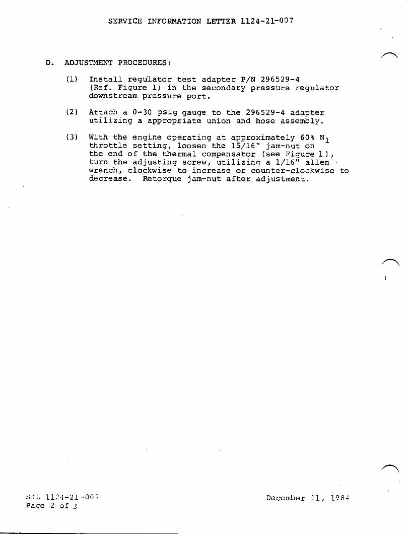
SERVICE INFOR},I.ATION LETTER LL24-2L-OO7
D. ADJUSTMENT PROCEDURES:
(1) Install regulat,or test adapter P,/N 296529-4(Ref. Figure 1) in the secondary pressure regulatordownstream pressure port.
(21 Attach a 0-30 psig gauge to the 296529-4 adapterutilizing a appropriate union and hose assembly.
(3) With the engine operating at approximately 608 Nlthrottle setting, loosen the L5/L6" jam-nut onthe end of the thermal compensator (see Figure I ),turn the adjusting screw, utilizinc; a L/tA" allenwrench, clockwise to increase or coun'ter-clockwise todecrease. Retorque jam-nut after adjustment.
I
srL I1l4-21 -007Page 2 of 3
December Il, 198.1
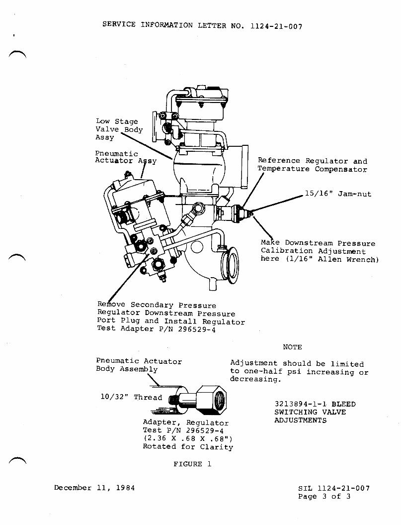
SERVICE INFORI4ATION LETTER NO. IL24-21-007
Low StageValve
-BodyAssy
Pneumati_cActuator sy
Port Plug and fnstall RegulatorTest Adapter p/N 296529-4
\\Make Downstream pressureCalibration Adj ustmenthere (l/16" Allen Wrench)
NOTE
Adjustment should be limitedto one-haIf psi increasing ordecreasing.
Reference Regulator andTemperature Compensatol:
L|/rc" Jam-nut
3213894-L-1 BLEEDSWITCHING VATVEADJUSTMENTS
srl, IL24-21-007Page 3 of 3
T
Pneumati_c ActuatorBody Assembly
L0/SZ" Thread
Adapter, RegulatorTest P/N 296529-4(2.36 X .68 X .69")Rotated for Clarity
FTGURE 1
December 11, l-984
TilT{SERY'CEINFORMATION LETTER
SIL NO. IL24-2L-013 February 6, 1985
SUBJECT: APPRO\IED ALTERNATE LUBRICATiITS FOR AIRESEARCH COOLINGTURBINE 572375-L-2 and -3.
EFFECTfVITY: MODEL $IESTWIND LL24/LL24A, all serial numbers.
A. REASON
To provide an aLternate list of cooling turbine lubricants.B. REFERENCES
Airesearch Operations and Maintenance Instructions Report,No. 4-272 and Qualified Products List-23699-1I.
C. PUBLTCATIONS AFFECTED
The LL24 Maintenance Manual, Chapter L2, will be revised toinclude aLternate oil-s reflected in this SIL.
D. DESCRIPTION
The following lubricants listed under MIL-L-23699 may be usedas a substitute for Exxon 2380 and Mobil Jet II Oil. Allproducts listed herein have been qualified under therequirements for the product as specified in the latesteffective issue of the applicable specification. This Iistis subject to change without notice; revision or amendment,of this list will be issued as necessary. The listing of aproduct does not release the supplier from compliance withthe specification requirements.
/ srr, IL24-21-013Page I of 7
SUBSIDIARY OF ISRAEL AIRCRAFT INDUSTRIES, LTD.
BEN GURION AIRPORT, ISRAEL
@lillsmsp*t*,t#;,*,,*February 6, 1985
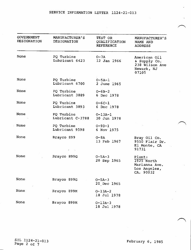
SERVICE INFORMATION LETTER LL24-21-013
GOVERNMENT MANUFACTURERIS TEST OR MANUFACTURER'SDESIGNATION DESIGNATION QUALIFICATION NAME A\]D
FEFERENCE ADDRESS
None Pe rurbine o-7A American oilLubricant 6423 12 Jan 1966 & Supply Co.238 Wi-Ison AveNewark, NJ07r05
None PQ Turbine O-5A-lLubricant 5700 2 June 1965
None Pe Turbine A-68-2Lubricant 3889 6 Dec L978
None PQ Turbine O-GC-ILubricant 3893 6 Dec 1978
None PQ Turbine O-13A-ILubricant C-3788 30 Jun L978
None PQ Turbine O-9D-1Lubricant 9598 6 Nov 1975
None Brayco 899 O-8A Bray Oil Co.13 Feb 1967 9550 Flair Dr.
El Monte, CA, 91731
None Brayco 899c O-5A-3 plant:20 Sep 1955 lFnorth
Marianna Ave.Los Angeles,cA. 90032
None Brayco 899c O-5A-320. Dec 1955
None Brayco 899M O-I3A-218 Jul 1978
None Brayco 899M O-13A-318 Jul 1978
srl. 1124_21_013Page 2 ot 7
February 6, l9B5
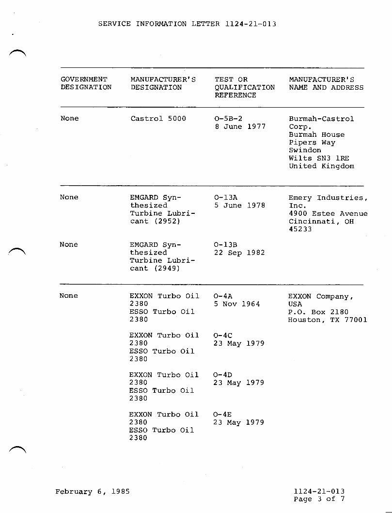
SBRVICE INFORMATION LETTER LL24-21-OI3
GOVERNMENT MANUFACTURERIS TEST OR MANUFACTURERISDESIGNATION DESIGNATION OUALIFICATION NAME AND ADDRESS
REFERENCE
None Castrol 5000 O-5B-2 Burmah-CastroI8 ilune 1977 Corp.
Burmah HousePipers WaySwindonWilts SN3 lREUnited Ki-ngdom
None
None
EMGARD Syn- O-13AthesizedTurbine Lubri-cant (2952)
EMGARD Syn- O-I3BthesizedTurbine Lubri-cant (2949)
Emery Industries,5 June 1978 Inc.
4900 Estee AvenueCincinnati, OH45233
22 Sep 1982
None EXXON Turbo Oil O-4A2380ESSO Turbo OiI2380
EXXON Turbo Oil O-4C2380ESSO Turbo Oi12380
EXXON Turbo Oil O-4D2380ESSO Turbo Oil2380
EXXON Turbo Oi1 O-482380ESSO Turbo Oil2380
EXXON Company,5 Nov L964 USA
P.O. Box 2IB0Houston, TX 7700I
23 l{,ay 1979
23 May 1979
l-r24-21-013Page 3 of 7
February 6, 1985
23 May 1979
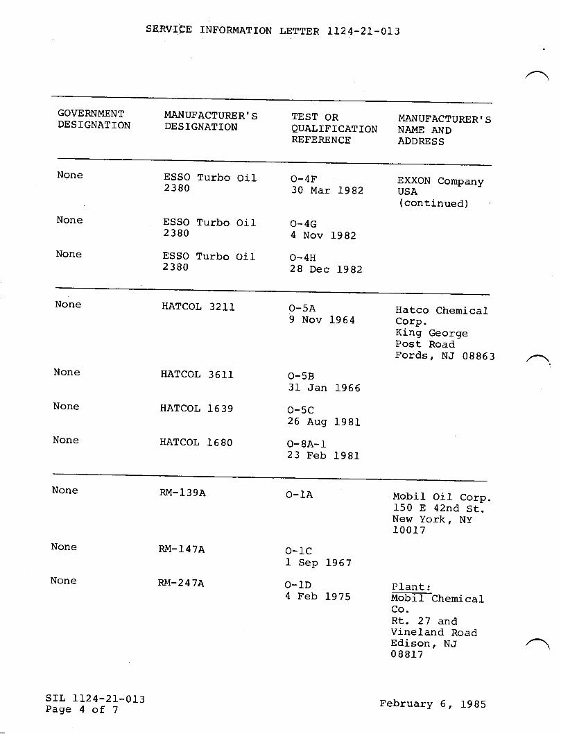
SERI/IFE TNFORMATTON LETTER LI24-21-013
GOVERNI'IENT MANUFACTURERT S TEST OR MANUPACTURERI SDESIGNATION DESIGNATTON QUALIFICATION NAI{E A\TDP€FERENCE ADDRESS
None ESSO Turbo Oi1 O-4F EXXON Company23Bo 3o Mar rgg2 usA(continued)
None ESSO Turbo Oil O-4G2380 4 Nov Lgg2
None ESSO Turbo Oil O_4H2380 28 Dec Lg82
None HATCOL 32IL O_5A Hatco Chemical9 Nov L964 Corp.
King Georgepost RoadFords, NJ 09963 .
None HATCOL 3611 O-5831 Jan 1966
None HATCOL 1639 O_5C26 Aug 1981
None HATCOL 1690 O-gA_l_23 Feb 1981
None RM-139A o-1A Mobil Oil Corp.150 E 42nd St.New York, Ny100 17
None
None
srr, 112 4-2I-0I3Page 4 of 7
RM-147A
wr-247A
o-1c1 Sep 1967
o-1D Plant:4 Feb 1975 MoETf-Cfremical
Co.Rt. 27 andVineland RoadEdison, NJ08817
February 6, 1985
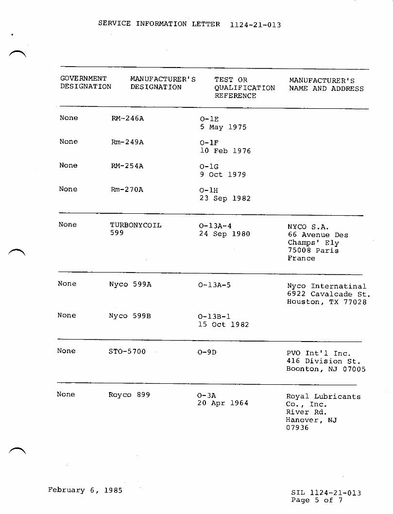
SERVICE INF'ORMATION LETTER IL24.21.013
GOVERNMENT MANUFACTURER'S TEST OR MANUFACTURER'SDESIGNATION DESIGNATION QUALIFICATION NAME AND ADDRESS
REFERENCE
None RM-245A O-lE5 May 1975
None Rm-249A O-IF10 Feb 1976
None RM-254A O-lc9 oct 1979
None Rm-270A O-IH23 Sep 1982
None TURBONYCOIL o-13A-4599
NYCO S.A.24 Sep 1980 66 Avenue Des
Champs' Ely75008 pari-sFrance
None Nyco 599A
None Nyco 5998
o-13A-5
o-138-115 Oct 1982
Nyco Internatinal6922 Cavalcade St.Houston, TX 77028
None STO-5700 o-9D PVO Intrl Inc.416 Division St.Boonton, NJ 07005
None Royco 899 o-3A Royal Lubricants20 Apr 1964 Co., Inc.
River Rd.Hanover, NJ07 936
srl, LI24-21-013Page 5 of 7
February 6, 1985
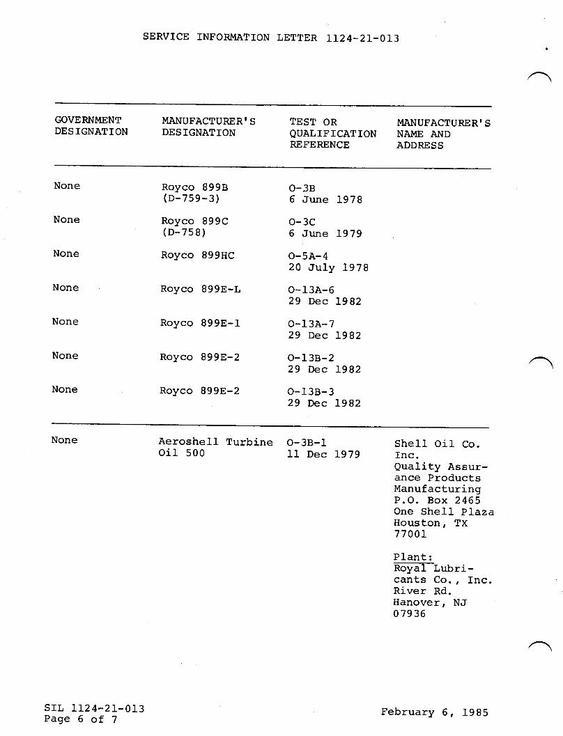
SERVTCE INFORMATION LETTER T124-21-013
GOVERNMENT MANUFACTURERI S TEST OR MANUF'ACTURER' SDESIGNATION DESIGNATTON QUALIFICATION NAI{E A}TDREFERENCE ADDRESS
None Royco 8998 O-38(D-259-3) 0 June L97g
None Royco B99C O-3C(D-758) 6 June L979
None Royco 899Hc O-5A-420 July L978
None Royco B99E-L 0-13A-629 Dec L982
None Royco 899E-I O-13A-729 Dec L982
None Royco g99E-2 o-13B-229 Dec L982
None Royco g99E-2 O-l3B-329 Dec L982
None
SIL IL24-2L-OL3Page 6 of 7
Aeroshell Turbine 0-38-1 Shell Oil Co.oil s00 11 Dec 1979 Inc.Quality Assur-ance ProductsManufacturingP.O. Box 2465One She11 PlazaHouston, TX77 00r
PIant:no@t ubri-cants Co., Inc.River Rd.Hanover, NJ07936
February 6, 1985
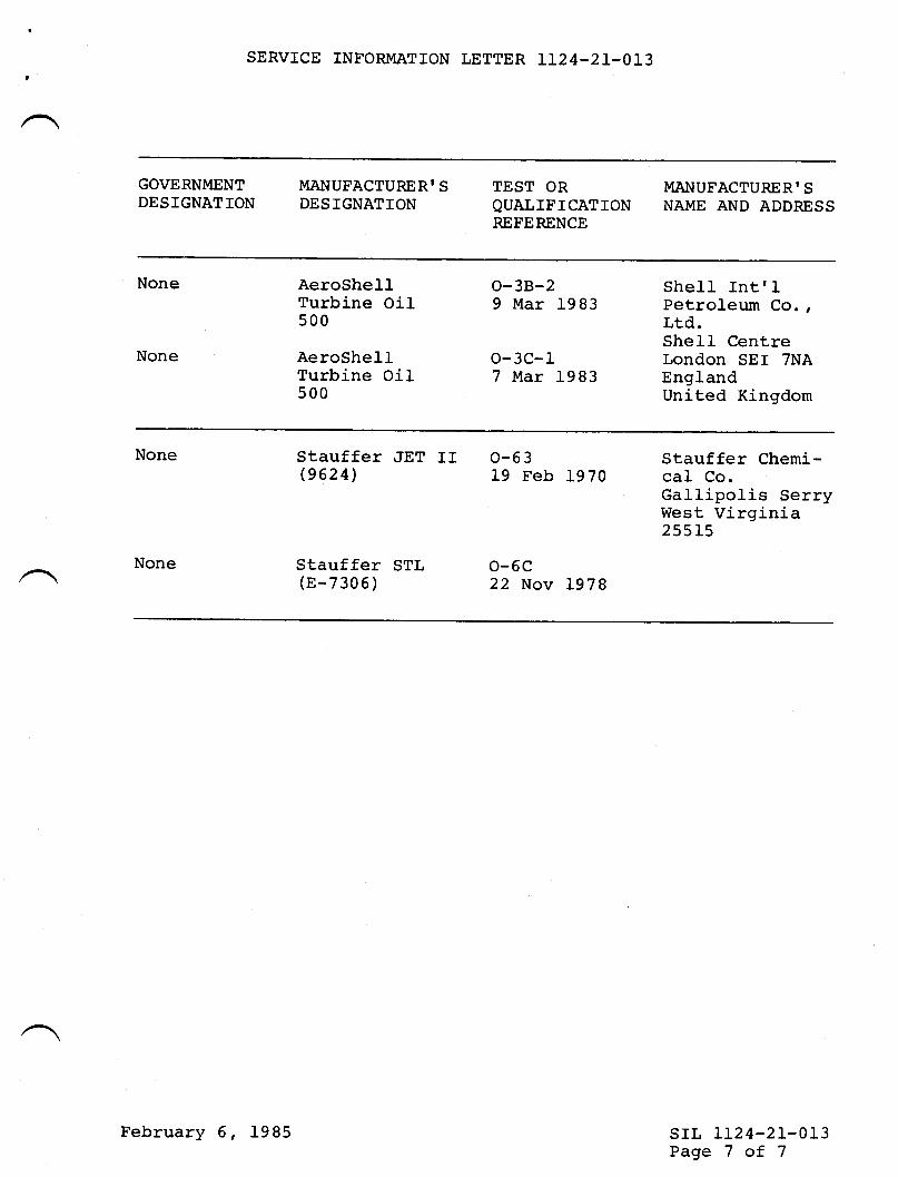
,SERVICE INFORMATION LETTER LL24-21-013
GOVERNI\,IENT MANUFACTURERI S TEST OR MANUFACTURERI SDESIGNATION DESIGNATION QUALIFICATION NAME AND ADDRESS
REFERENCE
None
None
AeroShell 0-38-2 Shell Intr ITurbine Oil 9 Mar 1983 petroleum Co.,500 Lrd.
Shell CentreAeroShell O-3C-1 London SEI 7NATurbine Oil 7 Ivtar 1983 England500 united Kingdom
None
None
Stauffer iIET II 0-63(9624)
Stauffer STL O-6C(E-7305) Z2 Nov 1978
Stauffer Chemi-19 Feb L970 caI Co.
Gallipolis SerryWest Virginia255ls
srl, LL24-21-013Page 7 of 7
February 6, 1985
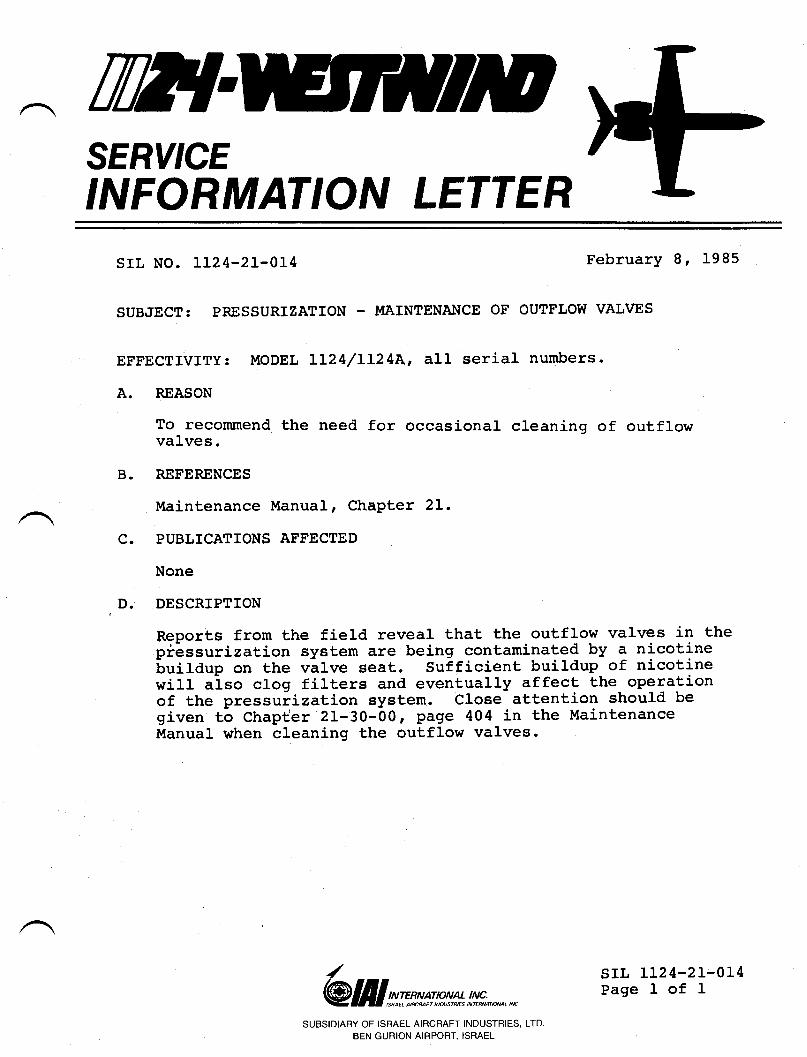
TWISERY'CEINFORMATION LETTER
SrL NO. LL24-2L'OL4 February 8, 1985
SUBJECT: PRESSURIZATION - MAINTENAI{CE OF OUTFLOW VALVES
EFFECTIVITY:
A. REASON
c.
B.
To recommend the need for occasional cleaning of outflowvalves.
REFERENCES
Maintenance Manual, ChaPter 2L.
PUBLICATIONS AF'FECTED
None
DESCRIPTION
Reports from the fiel-d reveaL that the outflow valves in thepiessurization system are being contaminated by a nicotineLuildup on the vlLve seat. Sufficient buiLdup of nicotinewill also clog fil-ters and eventual-J.y affect the operationof the pressuiization system. Cl-ose attention should begiven to chapter 21-30-00r pag€ 404 in the MaintenanceManual when cleaning the outflow valves.
MODEL LL24/LL24A' alL serial numbers.
/
@ III srxmptv** lt!s;,*,,*SUBSIDIARY OF ISRAEL AIRCRAFT INDUSTRIES, LTD.
BEN GURION AIRPORT. ISRAEL
D.
SIL LL24-2I-014Page l- of I
TWTSERY'CEINFORMATION LETTER
srl, No. LL24-2I-0L7
SUBJECT: COOLING TURBINE - OIL SUMP DRAINIMPROVEMENT
February 12, 1985
PLUG ACCESSIBILITY
A.
B.
EFFECTTVITY: MODEL LL24/LL24A WESTWIND aircraft, all serialnumbers.
REASON
To improve the accessibility of the cooling turbine oilsump drain plug.
REFERENCES
None.
PUBTICATIONS AFFECTED
None.
DESCRIPTION
As shown in Figure I, the cooling turbine mounting bracketblocks access to the oil sump drain plug. Routing out thebracketr eis shown, will allow the drain plug to be removedand replaced with a socket wrench. Trim no more materialthan necessary from the bracket.
c.
D.
/
@ lill srmss:t* !,!Y;.,*,,*
SUBSIDIAFIY OF ISRAEL AIRCRAFT INDUSTRIES, LTD
BEN GURION AIRPORT, ISRAEL
srr, II24-21-017Page I of 2
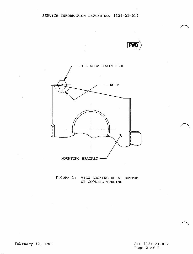
SERVICE INTORII,IATION LETTER NO. LL24-2L-OL7
OIL SUMP DRA]N PLUG
MOUNTING BRACKET
FIGURIT 1: VTIJW LOOKING UP AT IIOTTOMOT COOL]NG I'URBINI,:
srr, IL24-21-017Page 2 of 2
/l\=+- Pr)II'n
I
I
\+4>---\
,/
\
I
I
I
t_
February 12, t9B5
TWTSERY'CEINFORMATION LETTER
SIL No. LL24-2L-043 April 2. 1985
SUB;IECT: IMPROVED GASKETS FOR BLEED SWITCHING VALVE
EFFECTIVfTY: Ll24/LL24A WESTWIND, all serial numbers.
A. FEASON
To announce the availability of improved gaskets for usein the P/N 783647-3 bl-eed switching val.ve installation.Information supplied in this service information letter willbe included in the next scheduled revision to the LL24/LI24AILlustrated Parts Catalog.
B. REFERENCES
None
C. PUBLICATIONS AFFECTED
LL24/LL24A Illustrated Parts Catalog, Chapter 2L-20-00.
D. DESCRIPTION
When replacing a bleed switching valve also order kitnumber 21-4001 which will include all gaskets and hard$rarerequired for replacement of a BSV.
fnstall all gaskets in mating connections dry. Do not useRTV compounds of any type in the installation. fnstallall low and high pressure inlet flange bolts with Fel-proC5-A Hi-Temp anti-seize lubrication (or equivalent).
/
@lfllgmwmn*!t#*@alMsrl, LL24-2I-043Page I of 2
SUBSIDIARY OF ISRAEL AIRCRAFT INDUSTRIES, LTD.
BEN GURION AIRPORT, ISRAET
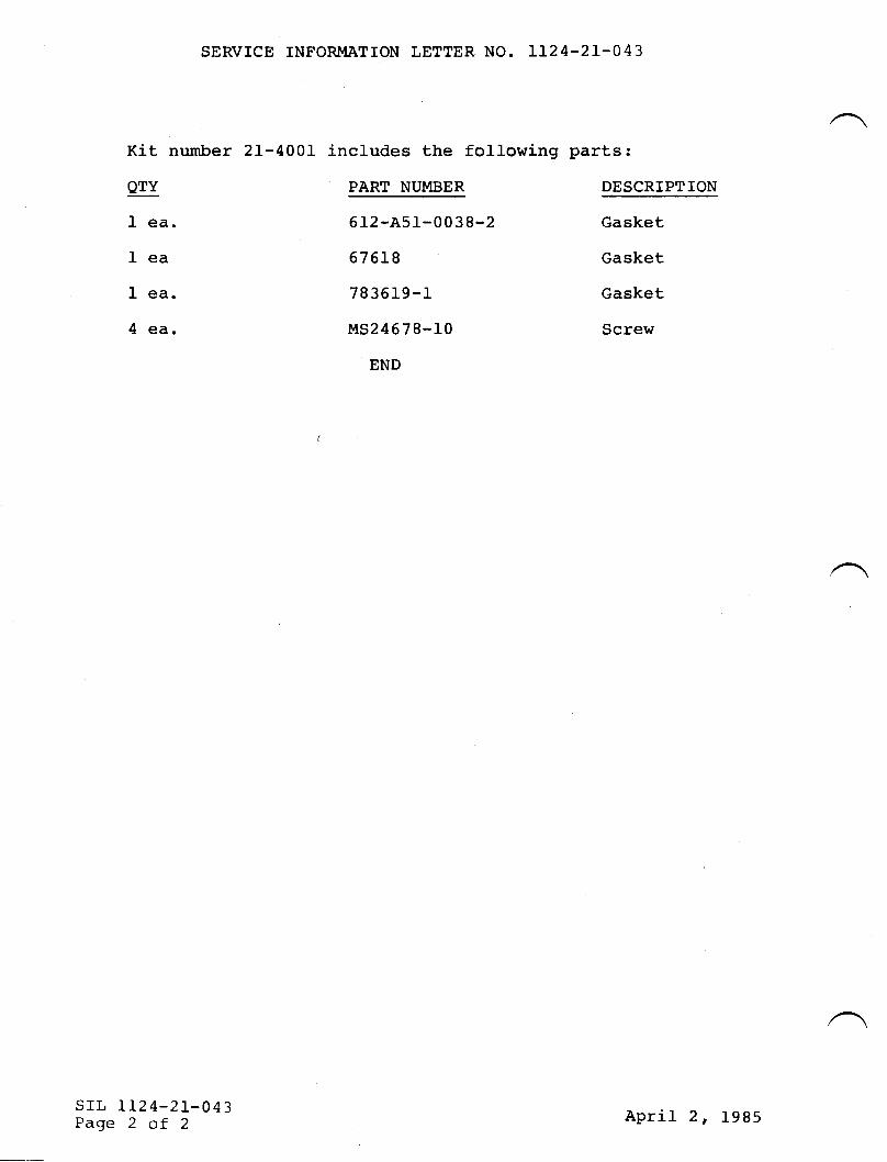
SERVICE INFORMATION LETTER NO. 1I24-2T.043
Kit number
QTY
I ea.
Iea
I ea.
4 ea.
srl, 1124-21-043Page 2 of 2
includes the following
PART NUMBER
6 12 -A51-0 0 3 8-2
67 6L8
78 3619-I
M524678-10
END
parts s
DESCRIPTION
Gasket
Gasket
Gasket
Screw
21-4001
April 2, 1985
ttllSERY'CEINFORMATION LETTER
SERVICE INFORMATION LETTER NO. IL24.2I.O66B June 30,1987
(This Service Information Letter No. LL24-21-0668 dated June 30,1987 supersedes SIL No. Ll24-2L-066A dated January 9,1987 and SILNo. Il?4-21-066 dated September 15, 1986 in thei r enti rety.)
SUBJECT: AIR C0NDITI0NING - IMPR0vED BLEED SUITCHING vALvE(Garrett P/tt 3213894-4-1)
EFFECTIVITY: LL2411124A M0DEL |r{ESTT{INDS, all serial numbers.
A.
B.
C.
REASON
T o al e rt LI24 operatorsbeen pub'lished by Garrett
REFERENCES
Garrett/Airesearch Service BulletinApril 30,1986, revised July 31,1986.
PUBLICATIONS AFFECTED
that a Service Bulletin revision hasregarding the switching valve.
No. 3213894-36-L42L dated
Il24lf124A Illustrated Parts Catalog, Chapter ?L.
DESCRIPTION
Attached, for your convenience, is page 3 of 4 of the revisedGarrett Service Bulletin No. 3213894-36-1421 dated April 30,1986, Revision No.1 dated July 31,1986. Page 3 of 4 reflectsthe only changes to this bulletin.
@ lI I wfxg plvtr !n!#;,*.,, *
SIL LT24.2L-0668Page I of t
SUBSIDIARY OF ISRAEL AIRCHAFT INDUSTRIES, LTD.
BEN GURION AIRPORT, ISRAEL
/
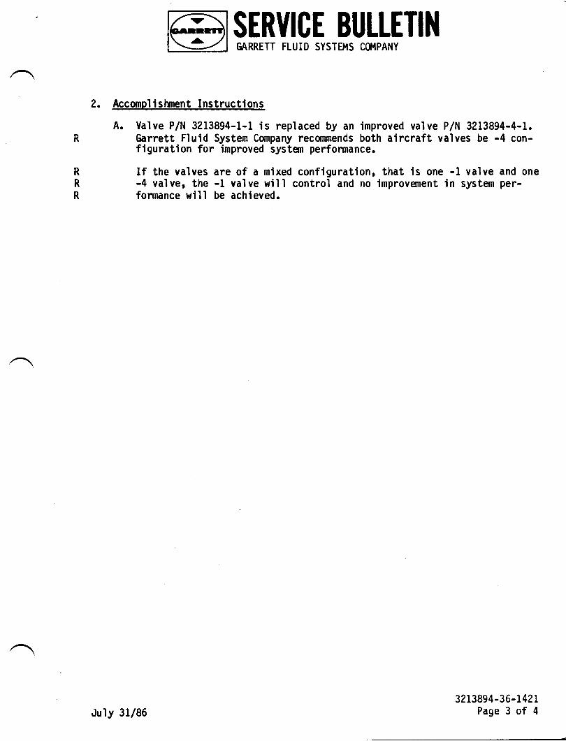
MI SERVICE BULLETINl\y I cARRETT FLUID sysrEr,ls c0MpANy
2. Accomplislunent Instructions
A. Valve P/N 3213894-1-1 is replaced by an improved valve P/N 3213894-4-1.Garrett Fluid System Company recorunends both aircraft valves be -4 con-figuration for improved system performance.
R
R
R
If the valves are of a mixed configuration, that is one -l valve and one-4 valve, the -1 valve will control and no improvement in system per-formance will be achieved.
3213894-3 6-t42rPage 3 of 4July 31/86
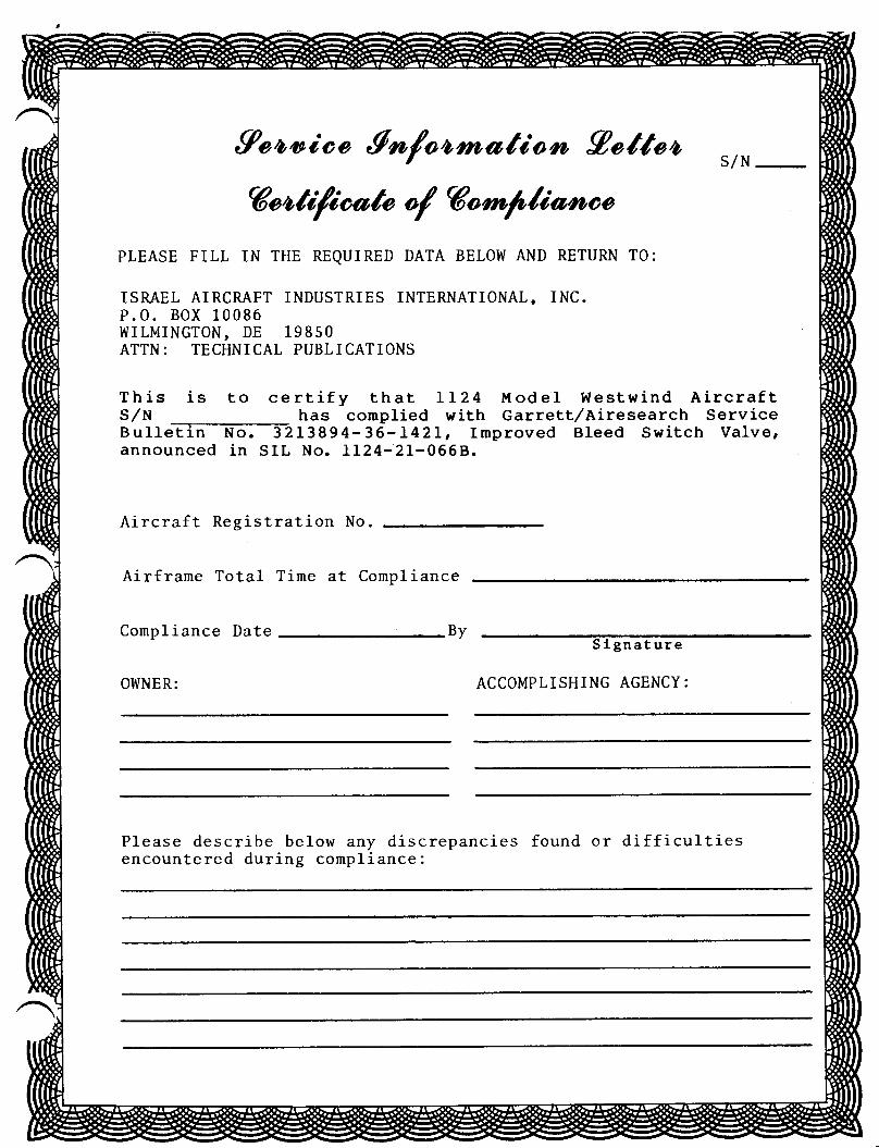
9eoryioo finfoomatioro 9ottoos/N
6"oti/ioato of G"rn/,liatooo
PLEASE FILL IN THE REQUIRED DATA BELOW AND RETURN TO:
ISMEL AIRCMFT INDUSTRIES INTERNATIONAL, INC.P.O. BOX 10086WILITIINGTON, DE 19850ATTN: TECHNICAL PUBLICATIONS
This is to certify that LL24 ModeI Westwind Aircrafts,/N _ has compried with Garrett/Airesearch servicesulleTT;-lm:- 321389 4-36-L42L, rmproved Bleed switch Valve,announced in SIL No. LL24-21-066B.
Aircraft Registration No
Airframe Total Time at Compliance
Compliance Date
OITNER:
ByS lgnat ure
ACCOMPLISHING AGENCY:
Please describe below any discrepancies found or difficultiesencountered during compliance:
TilE{SERY'CEINFORMATION LETTER
A.
B.
c.
D.
SERVICE INFORMATION LETTER NO. LL24-2I-069 JANUARY 16, 1987
SUBJECT: AIR CONDITIONING - III,IPROVED BLEED SWITCHING VALVE BODYSEALS
EFFECTMTY: LL24/LI24A WESTWINDS, all models
REASON
To announce the availability of a nelr, improved bleed switchingvalve body packing.
REFERENCES
GarreEt/Airesearch Service Bulletin No. 3213894-36-1419 datedllay 30, 1985.
PUBLICATIONS AFFECTED
LL24/LL24a Illustrated Parts Catalog' Chapter 2I.
DESCRIPTION
For your'convenience, a copy of Garrett Service Bulletin No.32L3894-36-14f9 is attached.
/@lfilsmtw*,y!*.** SIL LL24-2L-069
Page I of ISUBSIDIARY OF ISRAEL AIRCRAFT INDUSTRIES, LTD
BEN GURION AIRPORT, ISRAEL
5H{U|U[ BULLEililGARRETT PNEUMATIC SYSTEMS DIVISION
PNEUMATIC-PRESSURE REGULATING AND SHUTOFF VALVE
1. Planninq Information
A. Effectivlty
This serulce hrlletin is appl icable toshutoff pneumatic pressure lalve. --
Part l{o. Model No.
3213894-1-1 M
B. Reason
l'lay 30/86Copyright 1986 by The Garrett Corporation
- Replacement of High and LowPressure Inlet Flange packings.
the folloring regulating and
Prior toSerial No.
ALL
Appl ication
l{estwi ndtLzL/Lt?3/1124
Reports frsn the field and Garrett overhau'l shop have indicated a shortservice life of the high and low pressure flung. pii[i6; resulting inexcessive bleed-ai r leakage.
Garrett Pneumatic Systems Division has designed a ner.r packing configura-tion that reorientes the fibergla-s9 laminate.g0 degrees and provides ad-ditional squeeze for_ improveo ieiting: in-ioaiti;;,-iigh"Lmperaturetests have been completed to veriry lhe acceptabitilv oi the design.C. Description
This service bulletin provides instructions for removal of existingflange packings and reiracing with new impioveo static face searpacki ngs.
D. . Approval
Not applicable.
E. I'lanhour Requi rements
It is assumed that the unit is removed from the aircraft.No additional manhours are required to accomplish this change when per-formed at orerhaul or when repair necessitates access to the affectedpart.
3213894-36- 1419
Page I of 6
@ lF.BIll,q,F,, PllltE T I llF. Material - Price and Availabllity
Information regarding availability of parts may be obtained from one ofthe fol lowing facil ities.Garrett General Aviation Services Co., Los Angeles Intercontinental Air-port, 6201 West Imperial Flwy., Los Angeles, CA 90045.
Garrett General Aviation Services Co., MacArthur Airport, ZZZI SmithtownAvenue, Ronkonkoma, Long Island, Ny ll77g.
Garrett General Aviation Services Co., Houston Intercontinental Airport,17250 Chanute Road, Houston, TX l7Z0S.
Garrett General Aviation Sewices Co., p.0. Box 6g, Route 3, Bush Field,Augusta, GA 30910.
Garrett General Aviation services co., capitol Airport, p.0. Box ?!77,Springfield, IL 62705.
Garrett GMBH, Frankfurter - Strasse 51, Postfach 1150, 6096 RaunheimM/l'lai n, llest Germany.
Garrett singapore, Pty Ltd, 16l Gul circle, Jurong Town, p.0. Box 166,Singapore 9161, Singapore.
Garrett Aerospace Pty. Ltd., IB-ZZ Murray Street, Marrickville, NSl,l,2204 Austral ia.
G. Tool ing - Price and Availabil ityNo special tooling required except that already listed in referencedmanual ( s ).
H. lJeight and Balance
No change.
I. Publ ications References
None.
J. Service Bulletin References
None.
K. Other Publ ications Affected
None.
3213894-36-1419Page 2 of 6
tlay 30/86
@ l F'$ llj rq,,E,, -q||* H T l l{2. Accompl ishment Instructions
A. Separate valve into three major subassemblies to gain access to packingsas follows. (See Figure l.)(1) Remove four existing screws (1t1S16996-10) and loosen trbe bushing
nut of high pressure inlet assembly.
(2) separate high pressure inlet assembly from low pressure inletassembly.
(3) Remove and discard old packing (3171314-2).
N0TE: Existing studs (3163533-1) are 0.88 to 0.90 inch long and ex-isting studs (3163533-2) are 1.00 to l.0z inch long. Tag ex-isting studs when removed to facilitate reassembly.
(4) Remove two existing studs (3163533-l) and two existing studs(3163533-?) of low pressure inlet assembly.
(5) Separate low pressure inlet assembly from secondary pressure regulat-ing and shutoff assembly.
(6) Remove and discard old packing (3171314-1).
B. Assemble major subassemblies with new packings as follows. (See Figure1.)
CAUTION
ENSURE ALL OLD PACKING MATERIAL IS REMOVED FROM
FLANGE GROOVES PRIOR TO INSTALLING NEI.| PACKINGSTO PREVENT LEAKAGE.
(1) Install nan packing (3171314-3) and low pressure inlet assembly onsecondary pressure regulating and shutoff assembly. Secure with twoexisting studs (3163533-l) and bro existing studs (3163533-2).
(2) Install nevr packing (3171314-4) and high pressure inlet assembly on
l3x.offii:t':,llffiir:"il:l[ "llfl
n]:l'^ili,ifii' l:.#: ffi,llg!,li8i:C. Perform leakage check of valve as follows.
(1) Cap high and low pressure inlet ports.
(?) Install an adapter on the outlet port of secondary pressure regulat-ing and shutoff assembly.
(3) Connect an air source (100 psi) to adapter.
(a) Apply approximately 100 psig and using leak detection compound, checkfor leakage around new packing flanges and Ube fittings. Frothingand small bubbles are acceptable.
3213894-36-1419Itlay 30/86 Page 3 of 6
D.
@ lF'[]11'q,F",I]l]t E T I N
(5) Reduce air pressure to zero and remove adapter
Upon completion of tlris change, stamp Change No. ltification plate adjacent to IOD REC0RD.
and caps.
on the component iden-
3213894-36-1419Page 4 of G
llty 30/86
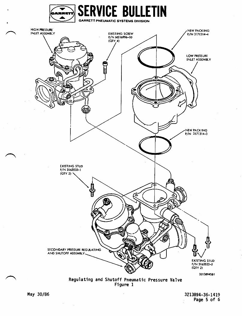
PIESStnEASSEMBLY
\\ \t
HIGHIN[EI
@ I F=$Iil-q,F",Pll"lhF T I 1{
EXISTING SIUDP/N 3163s33-l(orY 2)
\ \\
EXISTING SCREW
P/N trsr6996-t0@TY/1)
/,//l
NEW PACKINGP,/N 3l7l3l,f-,{
EXISTING STUDP/N 3163533-2(QTY 2)
32t3894581
3213894-36- 1419Page 5 of 6
)I
&|3
SECONDARY PRESSURE REGTJTATINGAND SHUTOFF ASSEMBIY
Regulating and Shutoff Pneurnatic Pressure ValveFigure I
tlay 30/86
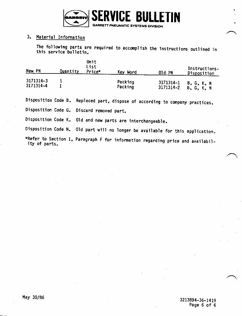
@l l"F'[yJ_q[.Pfltr E T r l{!
3. l.laterlal Infonnatlon
The followlng. p3lq.are required to accanplish the instructions outlined inthis service bulletln.
Uni tList Instructions_
New PN Quantitv Price* Kev ll|ord old pN Di--'-;-;---3171314-3 I3171314-4 I
Disposition Code B.
Disposition Code G.
Disposition Code K.
Disposition Code N.
*Refer to Section l,ity of parts.
Packi ngPacki ng
3171314-1 B, G, K, N
3171314-2 B, G, K, N
Replaced part, dispose of according to company practices.
Discard removed part.
0ld and new parts are interchangeable.
O'ld part will no longer be avdilable for this application.Paragraph F for information regarding price and availabil-
3213894-36-1419Page 6 of 6
May 30/86
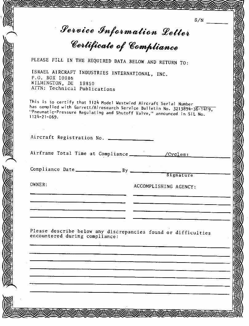
s,/u
9eo,,a i oo,Tn/oarmatio n gottoo
Geotif,ioote of Gom/,liatmoo
PLEASE FIIL IN THE REQUIRED DATA BELOW AND RETURN TO:
ISRAEL AIRCRAFT INDUSTRIES INTERNATIONAL, INC.P.0. BOx 10086wILI'|INGTON, DE 19950ATTN: Technical publications
This is to certify that 1124 Model Westwind Aircraft Serial Numberhas compl ied with Garrett/Airesearch service Bulletin No. trrjgg\167q;rrPneumatic-Pressure Regulating and Shutoff Valve,,' announced in Sl L No.1 124-21 -059
Aircraft Registration No.
Airframe Total Tine at Conpliance
ACCOMPLISHING AGENCY:
Compliance Date
OWNER:
By
Please describe.below all discrepancies found or difficultiesencount,ered during compliance :
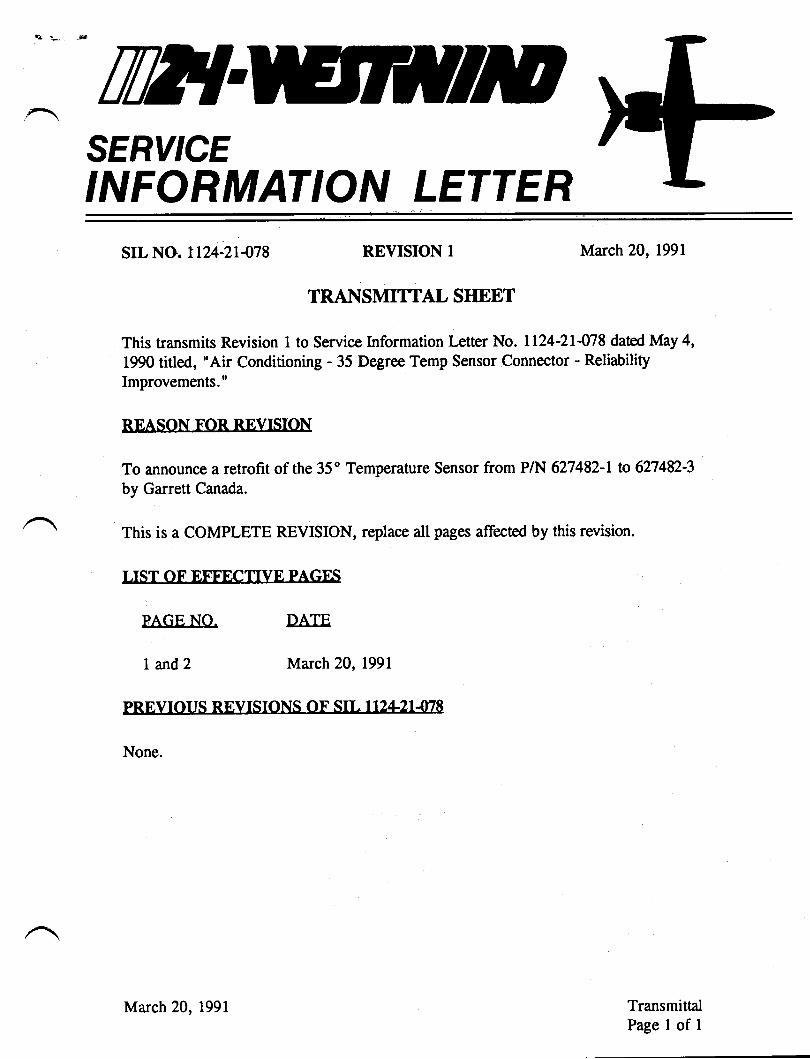
t:' 5
Til?{SERVICEINFORMATION LETTER
srl. No. 1124-21478 REVISION 1
TRANSMITTAL SIIEET
March 20, L99l
This transmits Revision 1 to Service Information Letter No. 1124-2I-W8 dated NIay 4,
1990 titled, "Air Conditioning - 35 Degree Temp Sensor Connector - Reliability
Improvements."
REASON F'OR REVISION
To announce a retrofit of the 35' Temperature Sensor from P/N 627482-L to 627482-3
by Garrett Canada.
This is a COMPLETE REVISION, replace all pages affected by this revision.
I IST OF EFFF'CTIVE PAGE'S
PAGE NO.
L and2
DArE
March 20, l99l
PRF'.VIOUS RFVTSIONS OF SJr. 1 t2421478
None.
TransmittalPage I of I
March 20,l99l
IWTSERY'CEINFORMATION LETTER
SERVICE INFORMATION LETTER NO. 1124.2T478 May 4, 1990
SU&IECT: AIR CONDITIONING . 35 DEGREE TEMP SENSOR
CONNECTOR . RELIABILITY MPROVEMENTS
EFFECTIVITY: MODEL ll24lll24L WESTWIND, all serial numbers.
A. REASON
To reduce the effects of dissimilar metal corrosion on the contacts of tempsensor connector, Pllll6 and ensure a more positive electrical connection.
To announce a retrofit of the 35' Temperature Sensor from Part Number627482-l to 627482-3 (IAI P/N 783649-3 ) by Garrett Canada.
B. REFERENCES
II24l L124A Westwind Maintenance Manual, Chapter 21-50{0.tl24lLL24A Westwind Wiring Diagram Manual, Chapter 21-0041.Ll24lLL24A Westwind Illustrated Parts Catalog, Chapters 21-20{0 and 21-6G00.
C. PUBLICATIONS AFFECTED
lI24ll124A Westwind Maintenance Manual, Chapters 5-20-05 and 21-50{0.Ll24ll124A Westwind Illustrated Parts Catalog, Chapters 21-2040 and 21-60{0.
D. DESCRIPTION
1. Perform a thorough visual inspection of P/Jl16, the 35 degree temp sensor plugand jack (A 10X magnifying glass is recommended). Check for evidence ofpitting and corrosion of the male pins (temp sensor side) and fordiscoloration and/or deposits on the female contacts of the aircraft connector.
1.
2.RR
May 4, 1990Revision 1, March 20, I99l5050
str. 1124-21478Page L of2
SERVICE INFORMATION LETTER NO. 1124-21478
(a) If pitting or corrosion is noted on the pins, attempt a thorough cleaningwith a Freon spray cleaner and cotton swabs.
(b) Completely clean all corrosion deposits from the female connector using aFreon spray cleaner and toothpicks (or other acceptable non-abrasivetool for thorough cleaning of the female contacts).
2. Prior to reconnecting P/Jl16, pack the temp sensor plug with DC4 compound(Dow-Corning). This compound will act as a moisture barrier and reduce thepotential for dissimilar metal corrosion.
NOTE: Recommend the inspection and packing procedure be accomplishedat every 150 hour inspection interval.
R 3. To further preclude dissimilar metal corrosion, Garrett Canada will retrofit theR temp sensor with a new connector having gold-plated contacts, whenR requested, in conjunction with repair action. An additional fee will beR charged for this retrofit.
R NOTF" Upon retrofit, the part number 627482-l will be changed to partR number 627482-3. New orders should be for PIN 627482-3.
str" 1124-2r-078R Page2of2
May 4, 1990Revision l, March 20, tggl
W{SERY'CEINFORMATION LETTER
SERVICE INFORMATION I,ETTER. NO. I T24-21485 December 27, 1990
SU&IECT: AIR CONDITIONING - 35'F TEMPERATURE CONTROLSENSOR INSTALLATION
EFFECTIVTTY: MODEL lL24lrl24| wEsrwIND, all serial numbers.
A. REASON
To prevent thread damage of the 35'F temperature sensor or the mounting boss.
B. REFERENCES
| 124 | IL24 A Westwind Maintenance Manual, Chapter 2 1-50{0.
C. PUBLICATIONS AFFECTED
L L24 | | 124 A Westwind Maintenance Manual, Chapter 2 1 -50-00.
D. DESCRIPTION
During installation of the 35'F temperature control sensor, an anti-seize
compound conforming to MIL-A-9078, should be used on the threads for ease
of installation and to prevent damage of the threads of the sensor or the
mounting boss.
December 27, 1990
5r27srL Ll24-21485
Page 1 of 1
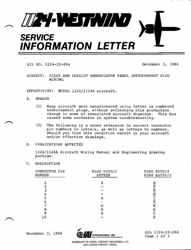
IWTSERY'CEINFORMATION LETTER
SIL NO. 1124-22-004 December 3, 1984
SUBJECT: PILOT AND COPILOT ANNUNCIATOR PANEL INTERCONNECT PLUGWIRING.
EFFECTIVITY: MODEL LI24/LI24A aircraft.A. REASON
(f) Many aircraft were manufactured using letter or numberedinterconnect plugs, without reflecting this productionchange in some of associated aircraft drawings. This hascaused some confusion in system troubleshooting.
(2) The following is a cross reference to convert connectorpin numbers to letters r Ers well as letters to numbers,should you find this condition exists in your aircraftand/or effective drawings.
B. PUBLICATIONS AFFECTED
LL24/IL24A Aircraft Wiring Manual and Engineering drawingpackage.
C. DESCRIPTION
CONNECTOR PINNUMBER
RPNg-II\EBcD
lB
;DE
I234567B
910
PLUG D32D/JLETTER
PLUG D55P/JPLUG D255P/J
srl, Ir24-22-004Page I of 2@ lI I s^t:ms p** t !,!!f;., *' *
SUBSIDIARY OF ISRAEL AIRCRAFT INDUSTRIES, LTD.
BEN GURION AIRPORT, ISRAEL
December 3, 1984
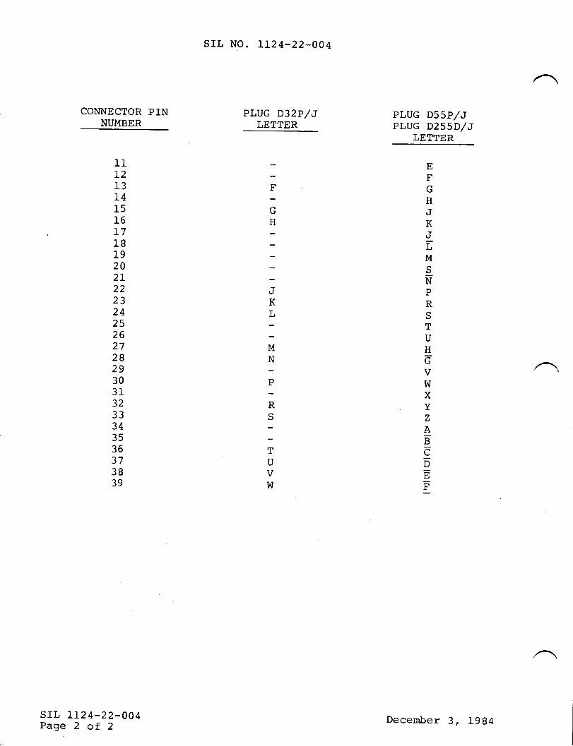
CONNECTOR PINNUMBER
srr, No. LL24-22-004
PLUG D32P/JLETTER
l112I3T41516I71819202I222324252627282930313233343536373B39
srL 112 4-22-004Page 2 of 2
EFG
HJKJLM
SNPRSTU
HdVW
XYzAEeDFE)
F'
F
GH
T
KT.
MN
;
RS
TU\/W
PLUG D55P/JPLUG D255D/J
LETTER
December 3, L9g4
.4 SERVICE PUBLICATIONS
revFlon nsrl., No, LL24-22-011Revision No. 1
SUBJECT:
ETTECTIVITY:
REASON FORREVISION:
February L7, 1986
AIR DATA/COMPUTER AND ALTIII{E,TER CERTIFICATIONPOR 1124A.
MODEL LL24A, aII serial numbers.
To expedite the receipt of Revision No. 3,SIL 1-80, to ALI-80( ) Batrometric Altimeter/ADC-80 ( ) /8L( ) /82( ) Air Data Computer.
Attached is a revised issue of ALI-80( ) Barometric Altimeter,/ADC-80 ( ) Air Data Computer Service Information Letter 1-80titLed, "Periodic Recertification of the ALI-80( ) BarometricAltimeter and ADC-8X( ) Air Data Computer according to FederalAviation Regulation (fAR) Part 91.17L", originally dated May15, 1980 and last revised November 20, 1984.
This revision clarifies the tests and specifications of FAR 43,Appendix E, Section (b) for field recertification.Black bars in the margin indicate where changes have been made.This revised issue entirely replaces the original.
Nrwuwu.rc.srr, 1124-22-0LLPage 1 of I
,LaAttdamif,lnn:
SutSrorAnY OF l8nACL AIFCFAFT tNOUSlnl€s. LtDECN OURION AIRPOET, ISNACI
TilT{SERY'CEINFORMATION LETTER
SIL NO. LL24-22-0LL December 21, 1984
SUBJECT: AIR DATA/COMPUTER AND ALTIMETER CERTIFICATION FORLL24A.
EFFECTIVITY: MODEL LL24A, all serial numbers
A. REASON
Attached is a copy of Rockwell-Collins SIL 1-80 Rev. No. 2for the ADC-80K and ALI-80 system recertification in accordancewith FAR 91.171.
This document details bench and in-aircraft recertificationprocedures, so you may use the method of your choice.
/ SIL TT24-22-OLLPage I of 1@ lil I s::n*s mn * !,!xfr;, ^.,, *
SUBSIDIARY OF ISRAEL AIRCRAFT INDUSTRIES, LTDBEN GURION AIRPORT. ISRAEL
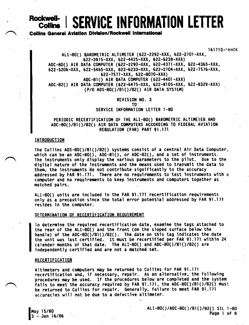
'M ISERI,ICE INFORMATI(I}I LETTERColllnr Gcnord Avlrtlon Dlvldon/Fochrcll Intmrtlonrl
I 6l 7l 0-'.rJrt0KALI-80( ) BARor4ErRlC ALTnIETER (622-2292-XXX, 622-2?01 -XXX,
622-3975-XXX, 622-4425-XXX, 622-6238-XXr)ADC-8oO AIR 0ATA CoIIPUTER (522-2290-XXX, 622-43?l-XXX, 622-4365-XXX,622-5206-XXX, 622-5465-XXX, 622-6233-XXX, 622-2704-XXX, 622-7576-XXX,
622-1 57't -XXX, 522-80?0-XXX)ADC-8rO AIR DATA C0IIPUTER (622-4401-xXX)
Aoc-82O AtR DATA CollPUrER (622-647s-XXX, 622-8105-XXX, 62?-8329-XXX)(P/0 ADS-8oO/81(\/82( ) AIR 0ATA SYSlEll)
REVISI0I{ N0. 3T0'
SERVICE I}IFOR}TAI TO}I LEITER I -80
PERIODTC RECERTIFTCATTOiI OF THE ALI-800 BARO}TETRTC ALTIIIEIER AND
ADC-8oO/ar1)/82O AIR 0ATA C$TPUTERS ACCoRoING T0 FEoERAL AVIA1l0l{REGULAIroil (FAR) PART 9r.l7l
INTRODUCTIOII
The Golltns ADS-8OO/81(rlg2O systems conslst of a central Alr Data Computer,which can be an ADC-80O, ADC-81O, or A0C-82O, and a set of lnstruments.The lnstruments only dtsplay the varlous parameters to the ptlot. Due to the'rligital nature of the lnstrunents and the means used to transmit the data tothem, the Instruments do not contrlbute slgnlflcantly to the accuracyaddressed by FAR 9l.l7l. There are no requlrements to test lnstruments wlth a
conputer and no requlrements to keep lnstruments and computers together asnatched palrs
ALI-80O unlts are included In the FAR 9l.l?l recertlflcatlon requlrementsonly as a precautlon slnce the total error potentlal addressed by FAR 91.171resldes ln the computer.
IETER|{INATIoN 0F RECERTIFICATloil REoUIREI4E}|T
1o determlne the reguired recertification date, examlne the tags attached tothe rear of the ALI-80O and the front (on the sloped surface below thehandle) of the A0C-80O/8IO/8?O. The date on thls tag lndlcates the datethe unlt was last certlfted. It must be recertlfled per FAR 9l.l7l w{thin 24
calender months of that date. The ALI-8OO and ADC-80O/at1l/82O arelndependently certlfted and are not a matched set.
BEcl8u!.tcA'llgx
Altimeters and computers may be returned to Colllns for FAR 91.171recertlflcatlon and, lf necessary, repalr. As an alternatlve, the followingprocedures may be used. If the procedures below are completed and the systemfatls to meet the accuracy requlred by FAR 9l .l?1 , the ADC-80O/81 ('l/82( ) mustbe returned to Colllns for repalr. Generally, fallure to neet FAR 9l.l7laccuracies will not be due to a defectlve altimeter.
I
ALr-80( )/A0C-80( ) /8r(',)/8?( ) SrLPage I
1 -80ofBIrr ul'lu,,,
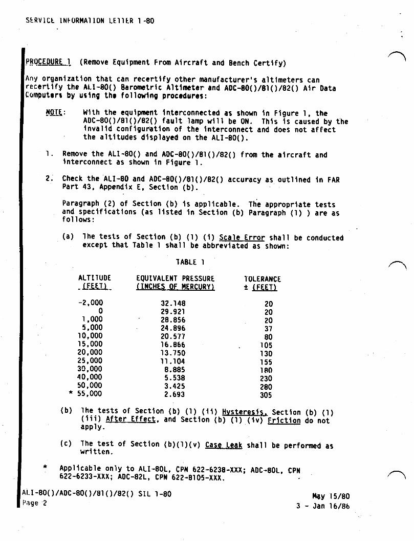
s[RVrcr tNFoR]tAr toN LEI I tR I -80
P!(|!LI)JBLI (Remove Equlpment From Atrcraft and Bench Certtfy)
Any organlzatlon that can reccrtlfy other manufacturer,s altimeters canreccrtlfy tho ALI-80O Baronatrlc Alilmatar and ADC-800 llt()/AZ( ) Atr DataComputrrr by urtng thr followlng procodurcs:
ttOTE: l{tth the cqulpment Intcrconncctcd as shown In Flgure l, theADC-80O/81(r/82( ) fault lamp wlll be 0tl. Thts ts caused by thelnvalld conflgunatlon of the lnterconnect and does not affect' the altltudes dtsplayed on the ALI-80O.
l. Remove the ALI-80O and A0C-80O/81 (l/82( ) from the alrcraft andlnterconnect as shown tn Flgure l.
2. Check the ALI-80 and ADC-B0O/AI1',/BZ( ) accunacy as ouillned ln FARPart 43, Appendix E, Section (b).
Paragraph (2) of Sectlon (b) is applicable. Th'e approprlate testsand-specifications (as llsted ln Section (b) Paragraph (l) ) are asfol lows:
(a) lhe tests of section (b) (l) (l) scale Error shall be conductedexcept that Table I shall be abbrevlated as shown:
ALT I I UDI
- LFJSLL.
-2,0000
1,0005,000
1 0,0001 5,000?0,00025,00030,00040,00050,000* 55,000
TAELE I
EqUIVALE}IT PRESSURT(IIICHT,S OF I{ERCURYI
32 .1 4829 .921' 28.85524.89620. 577I 6.866I 3.7501l .1048.8855.5383.4252.693
I'OLERANCEr (FEEI)
2020203780
105130155180230280305
(b) lhe tests of Section(iii) After Effect,appl y.
(c) The test ofwri tten .
(b) (1) (li) Hvsteresls. Sectton (b) (t)and Sectlon (b) (1) (lv) Frtctton do not
Sectlon (b)(l)(v) Case Leak shall be perfonned as
4qql !9able only to_ALI-901, Cpl{ 622-6238-XXX; AOC-BOL, Cpt{6?2-6233-XXX; ADC-821, Cpil 62?-8105-xxX
Af-r-80( )/Aoc-80( )/er 1 | /82( ) SrL 1 -80Page 2
ilay3-Jan
r 5/80I 6/86
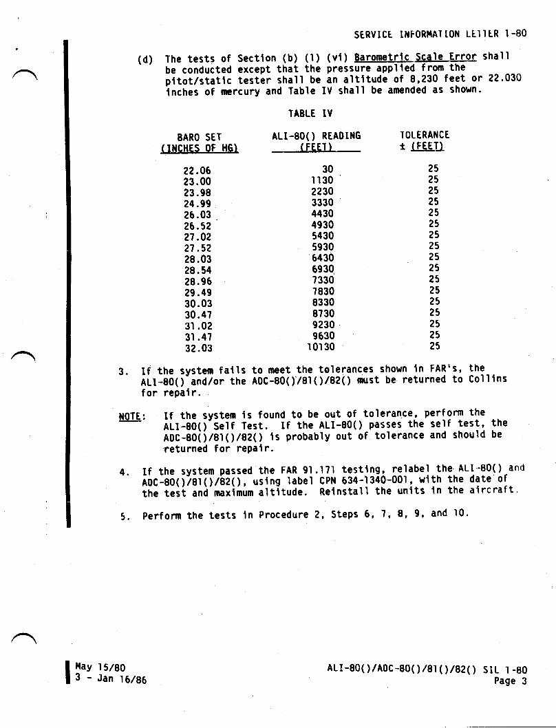
SERVICE ltfFoRllAT t0N LEI'l tR I -80
(d) The tests of Sectlon (b) (l) (vt) BarometFlc,Sgale Fl.lor shallbe conducted except that the pressure applled from thepitotltt.ttc testlr shall be an altltude of 8,230 feet or 22.030inches of rrercury and Table IV shall be amended as shown.
BARO SET(,I}ICHES OF HG)
22.0623.0023 .9824 .9926.03 .
26.5?27.0221 .5228.0328.5428.9529 .4930.0330.4731 .023l .4732.03
TABLE IY
ALI.8O() REAOING-- iitErrTOLERANCEt (fgE'LL
2525252525252525252525252525?5?525
30lr30'223033304430493054305930
'6430
5930,733078308330873092309630
10r30
3. If the system fatls to meet the tolerances shown in FAR's, the- AUt-g0O-and/or the A0C-80O/81( l/82( ) must be returned to Collinsfor repalr.
!!lIE: If the system is found-to be out of tolerance, perform the
-- lut-eO( )'Self Test. If the ALI-80( ) passes the self test, theADc-Bgaifarll/gZ( ) ls probably out of tolerance and should be'returned for rePair.
4. If the system passed the FAR 9l.l7l testing, relabel the ALl-80O and
A0C-g0(yTeftl t'AZtl, uslng label cPN 634-1340-001, with the date ofthe teit anC'maxiirum altituCe. Relnstall the units ln the aircraft.
5. Perforn the tests ln Procedure 2, Steps 6, 7, 8, 9, and l0'
l{ay l51803 - Jan 10186
ALr-80( )/ADc-80( )/81 ( ) /82( ) stL I _80
Page 3
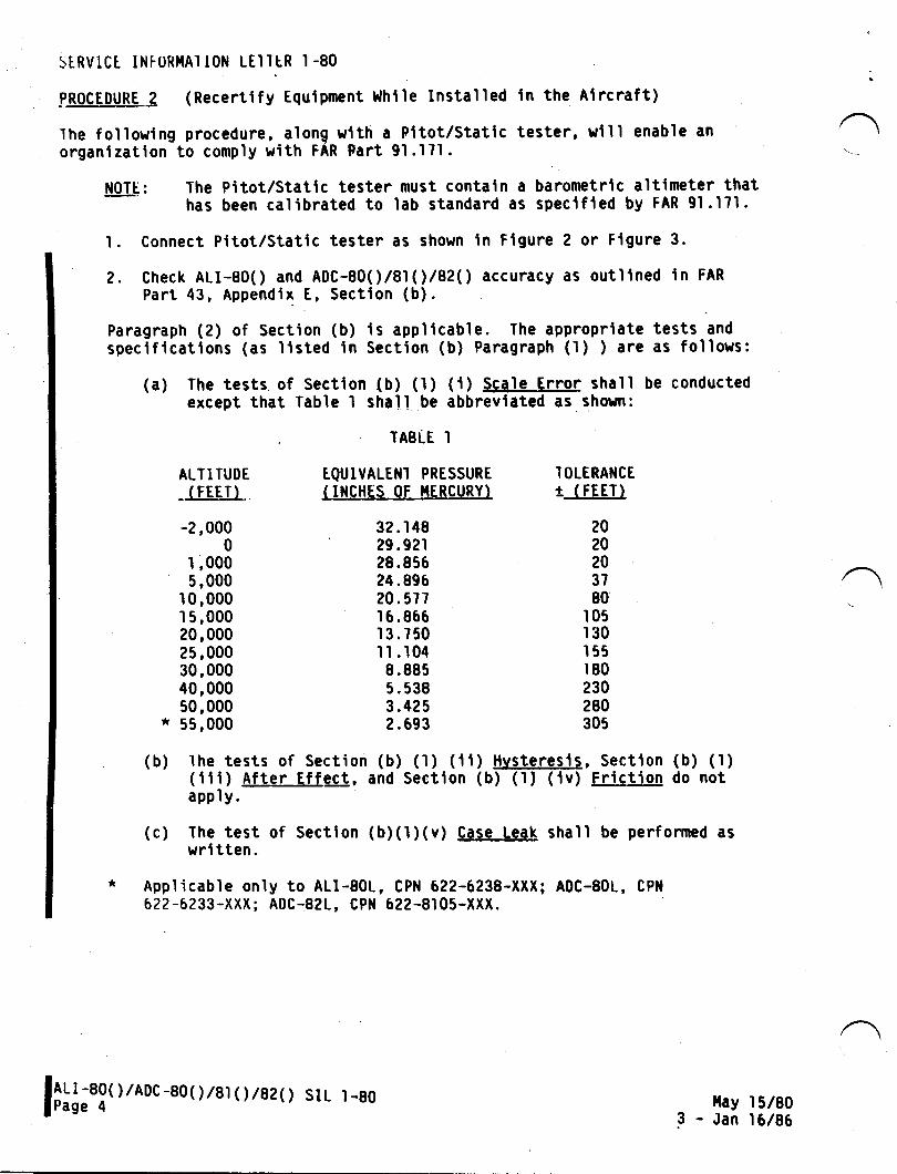
St RVlC[ INF0RI{A1 t0N LEI ltR I -80
psQgEgutsL2 (Recertify Equtpment l,lhlle Installed ln the Alrcraft)
The following procedure, along wlth a Fitot/Statlc tester, wlll enable anorganizatlon to comply with FAR Part 91.171.
l!0I!: l'he Pitot/Stattc tester must contaln a barometric altimeter thathas been calibrated to lab standard as specified by FAR 9l.l7l.
1. Connect Pitot/Static tester as shown in Flgure 2 or Flgure 3.
2. Check ALI-aOO and ADC-80O/81(l/82( ) accuracy as outltned ln FAR
Part 43, Appendix E, Sectton (b).
Paragraph (2) of Section (b) is applicable. The appropriate tests andspeciftcations (as listed in Section (b) Paragraph (l) ) are as follows:
(a) The tests of Sectlon (b) (1) (t) Scale Errof shall be conductedexcept that Table I shall be abbrevtated as shown:
ALT I TUDE
- (FEETI
-2,0000
1,0005,000
1 0,000I 5,00020,00025,00030,00040,00050,000* 55,000
TABLE I
EQUIVALENI PRESSURE( INCHES OF I.IERCURYI
32 .1 4829.92r28 .85624.89620.577I 6.866r 3.750I I .104I .8855.5383.4252.693
I OLERANCEtlEgu2020z03780
105r30155180230280305
,\
(b) lhe tests of Section (b) (r) (ll) Hvsteresis, Section (b) (l)(tii) After Effg!, and Section (b) (l) (iv) Frictio! do notapply.
(c) The test of Section (b)(1)(v) Case LeaL shall be performed aswri tten.
* App'licable on'ly to ALI-801, CPll 622-6238-XXX; ADC-801, CPN
62?-6233-XXX; ADC-821, CPN 622-8105-XXX
l6;tl, ) /Aoc -Bo( ) /s1(') /Bz(l llay l51803 - Jan 16186
sIL l-80
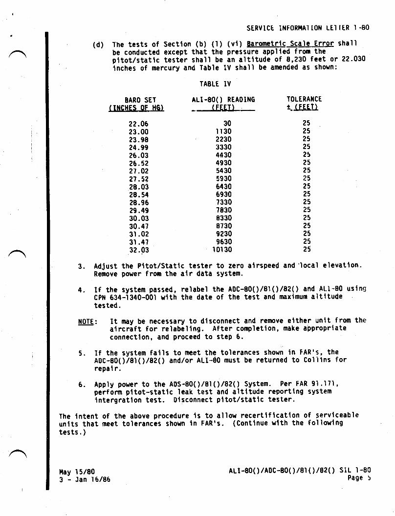
SERVtCt lNF0Rl.lAl lON LEI IER l -80
(d) 'l'he tests of Sectlon (b) (l) (vt) Barometfls Sqale.Efror shallbe conducted except that the pressure applled fr"om thepttot/statlc tester shall be an altltude of 8,230 feet or 22.030lnches of mercury and Table lV shall be amended as shown:
BARO SET( IIICHES OF HGT
22.0623.0023 .9824 .9926.0326.5227.02?7.5228.0328.5428.9629.4930.0330.473l .023l .4732.03
TAELE IV
ALr-80o REAoING
- (FEET} -
30lr3022303330443049305430593064306930733078308330873092309630
10'r 30
TOLERA}ICEt-lIgfl)
25252525252525?52525252525?5252525
3. AdJust the Pitot/Statlc tester to zero alrspeed and'local elevatlon.Remove power from the alr data systen.
4. If the system passed, relabel the A0C-80O/81 (')/82( ) and At.l-80 usingCPit 634-1340-001 wtth the date of the test and maximum altltudetested.
il0TE: It rnay be necessary to dlsconnect and remove elther unit fron thealrcraft for relabeling. After completlon, make appropriateconnection, and proceed to step 6.
5. If the system fails to meet the tolerances shown in FAR'S, theADC-S0O/81(l/82( ) and/or ALI-60 must be returned to Colllns forrepal r.
6. Apply power to the A0S-80O/8IO /82( ) System. Per FAR 91 .171'perform pltot-statlc leak test and altitude reportlng systemlntergration test. 0lsconnect pltot/statlc tester.
The lntent of the above procedure ls to allow recertlflcation of Servlceableunits that meet tolerances shown ln FAR's. (Conttnue wlth the follow'lngtests. )
l{ay3-
r 5/80Jan I 6/86
ALr-80( )/ADC-80( )/81 ( | /82( ) SlL I -80Page 5
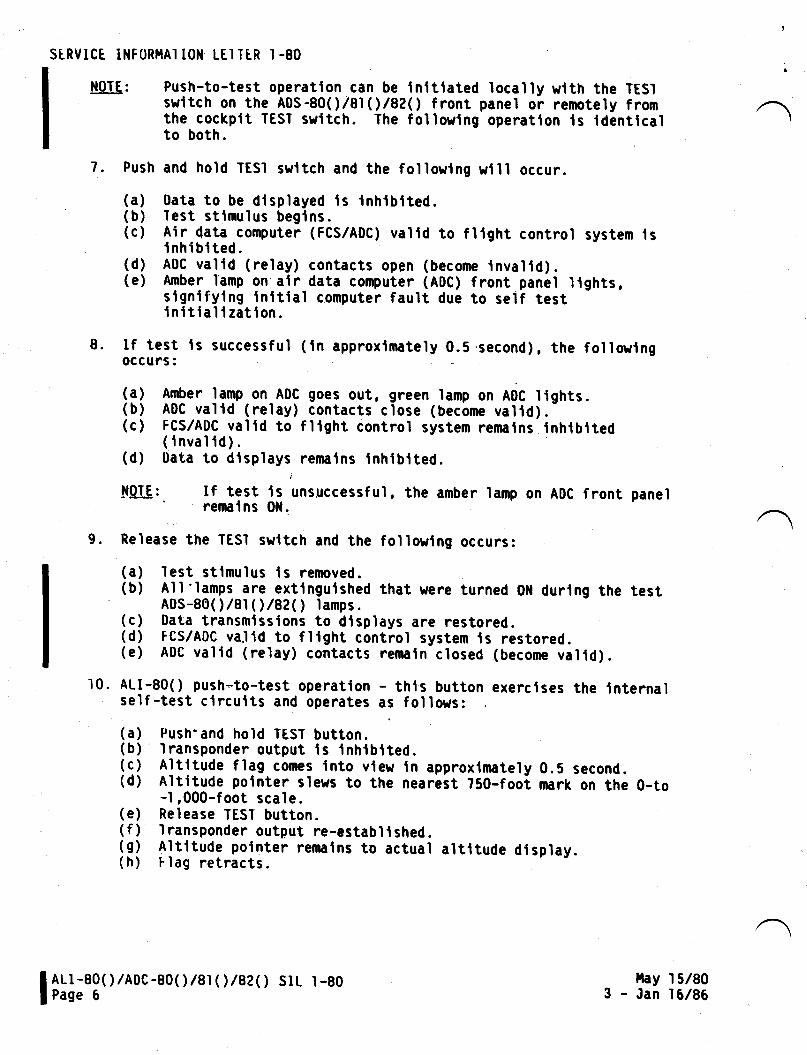
SIRVICE INFORI.IAI ION LEI TIR I -80
NOTE:
ALI-80( )/ADC-80( )/81 ( l/82( ) SrL l-80Page 6
Push-to-test operation can be lnltlated locally w.lth the TESIswltch on the A0S-80O/81(r/92( ) f ront panel or remotely f romthe cockptt TEsr swltch. The followlng operailon ls ldenilcalto both.
7. Push and hold TESI swltch and the followlng wlll occur.
(a) 0ata to be dtsplayed ls tnhtbtted.(b) Iest stlmulus beglns.(c) Air data computer (FCS/ADC) valld to fllght control system lsi nhi bt ted.
(d) ADC valtd (relay) contacts open (become tnvaltd).(e) Amber lamp on alr data computer (A0C) front panel lights,signlfying Inttlal computer fault due to self testinitiallzation.
lf test ls successful (in approximately 0.5.second), the followlngoccurs:
(t) Aqrler lgmp on-A0C goes out, green lamp on ADC ltghts.(b) ADC valid (relay) contacts close (become valtd).-(c) Fcs/ADc valid to fllght control system remalns lnhtblted( inval id) .
(d) Oata to dlsplays remalns lnhlblted.
IOTE: If test ls unsuccessful, the amber lamp on ADC front panel' remalns Oil.
9. Release the TESI swltch and the followlng occurs:
(a) lest stimulus is removed.(b) All'lamps are extlngulshed that were turned Olt durlng the testA0s-80( )/Bl ( | /az1) tamps.(c) 0ata transmissions to dtsplays are restored.(d) FCS/ADC va.ltd to fllght control system ls restored.(e) At)c valid (relay) contacts remaln closed (become valtd).
10. ALI-80O push-to-test operatlon - this button exercises the lnternalself-test clrcuits and operates as follows:
(a) Push'and hold TEST button.(b) Iransponder output ts Inhtbtted.(c) A'ltitude flag comes lnto vlew ln approxlmately 0.5 second.(d) Altitude polnter slews to the nearest 750-fooi mark on the 0-to-1,000-foot scale.(e) Release TEST button.(f) Iransponder output re-establlshed.(g) Altitude polnter remalns to actual aliltude dlsplay.(h) Flag retracts.
8.
ltay l51803 - Jan 16/86
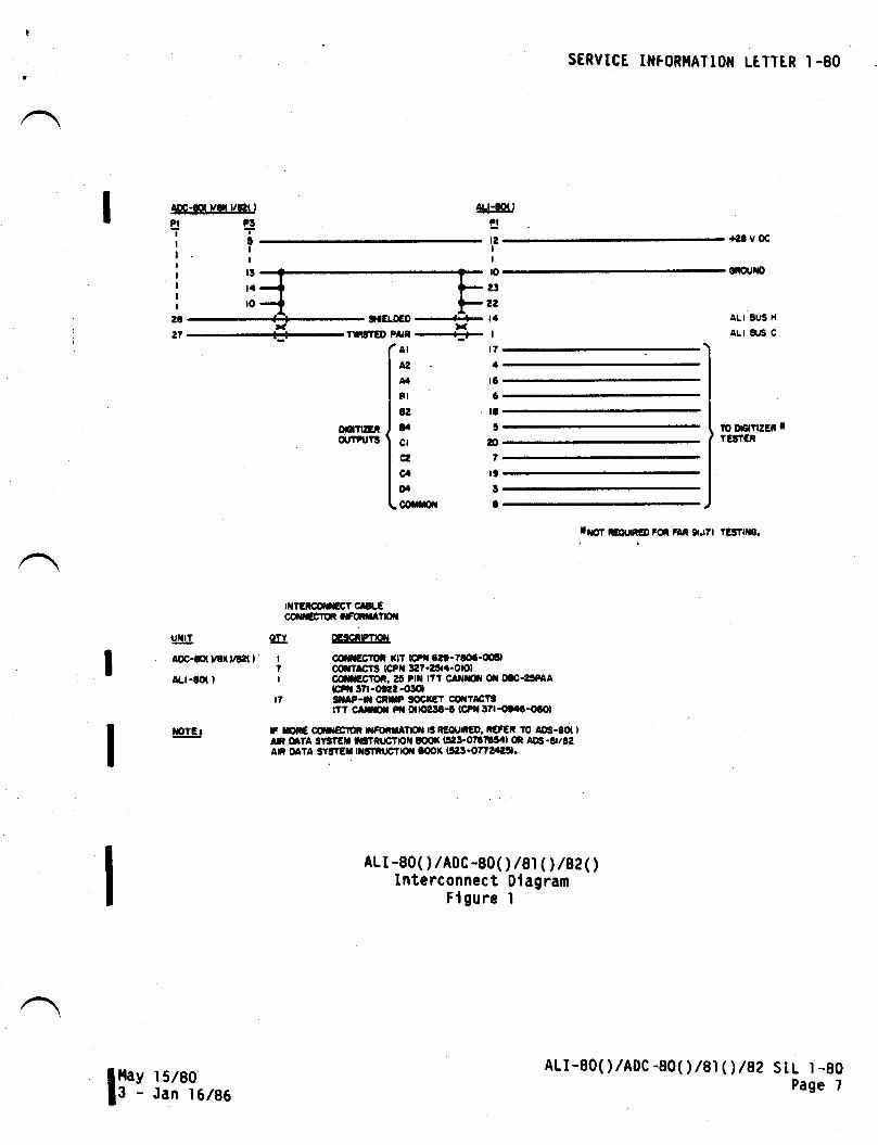
STRVICE II{FOR}IATTOI{ Lt,TTER I.8O
AOC-d ver vet I
e!I
UTIT
AOC-&(yB0/&l( )
aLt-to( )
IOTEI
9rcr-0€0TWTED Pxi ---,-
ALr-Sil
a!9a
gIItslatoI
2e
2?
tilT€iodnGT cllLEcdrErfi trftnlAton
9[r 9Esslg!.| flccroi nr €pl6et-7!oa-o(El7 oiltacTs tcPil:127-etl.-ololI c*c10i,2!t Ptx lr? clilsr il otc-a5PAA
G?rr !71-oe22-Ot.|t7 3i P-ff CirF lOCreT CilTlCTS
|TT CtmX P'| Ot@:L€ (cPil l7l-otiL-oGol
|F rcic @rr|Eror r$oira?tof{ t3 RtounEo, ieFEi !o ADs-6o( |An UTA 3vsrEr ngtRrrr|oil m( l3il3-o?311!'al m Aqt-6t/t2an oaTA sygtEr rtsTnrrtlfl tq,t( l5:l!-o77eac!1.
ALr-80( )/ADC-80( )/81( | /82(')Interconnect 0lagram
Flgure I
ALI 8US H
ALI AJS C
10 o6rflzEi rTEJfCR
rilot @un€o FoR FAt 9r.r?l
ALI-80( )/AoC -80( )/81 ( )/8? stL 1 -80Page 7
23
22
taI
t71
r6
6
ta
oonzEiot ?turs
AI
^2nFI
a2
t.clg2
q0.corn|
6Itl!
I
I ilay I 5/s013 - Jan 16186
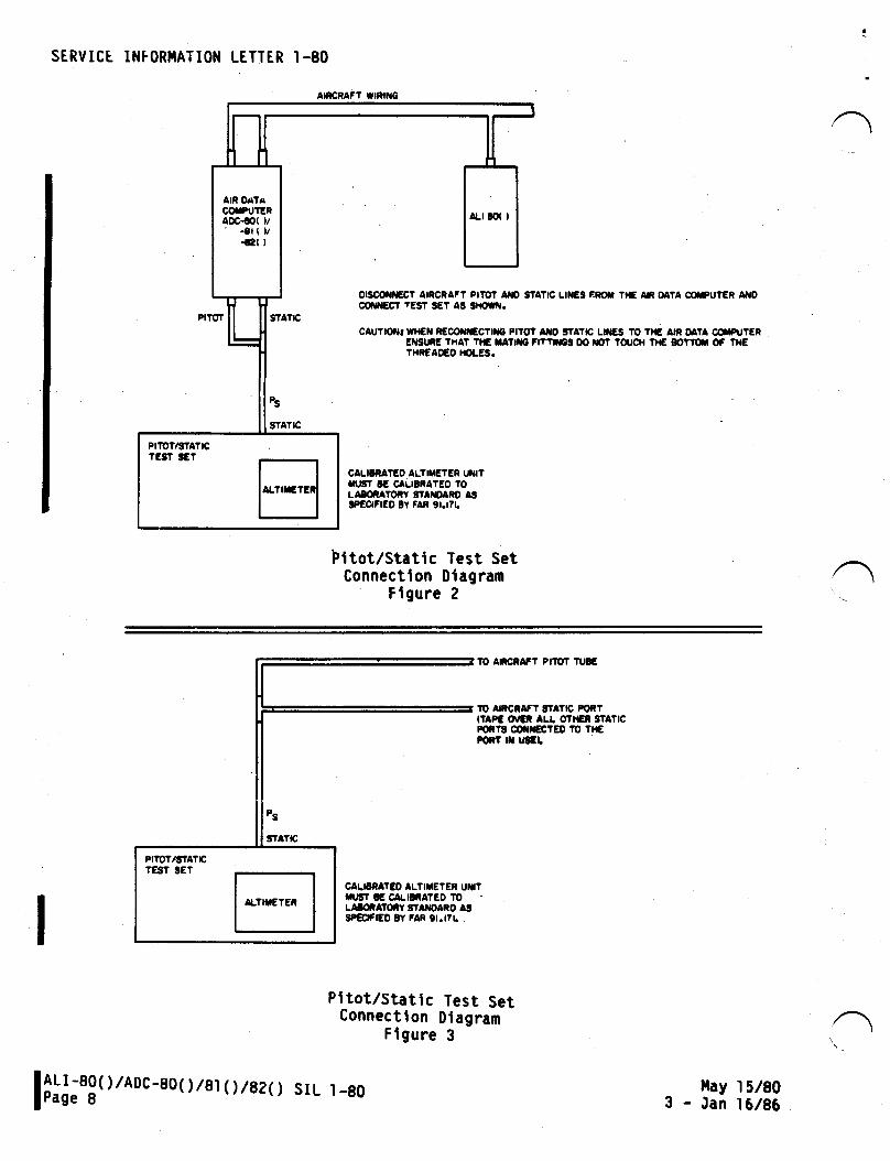
AnctaFt trntilG
I--l[AIR OATAC*UTERaoc-s( )/' -8t( )/
-t2( )
a|.t tq I
J orscofiiEct ATRCRAFT p|lor AID stco{ilEqr fEsT sET As s|rourr.
STATC
CAUTTOII wr{€l i€coif,€cTtre PtrotEIU'UiE THAT
'I{E TA?ilIO
'THNEAO€O IOLES.
Ps
STATrc
CAL|tNATEO ALTITIETEN UilITTU!iT !E CALIEiATEO TOLAtoiaToiv gTAitoAto astPEClFrEo lY FAR 9r.t7t.
PITOT
t_
PIID?/TITATICrEgf 3ET
SERVICT INFORI.IATION LETTER I-80
S'ATIC LII{€g EROX TIt€ AF OATA ffUTER A'{O
fi AXO SIATIC LtiES TO T}€ AIi OATA fft'T€NB;l"NreS OO TFT TOICH TH€ 8OTftN OF TIT€
Pttot/static Test setConnectlon Dlagram
Flgure 2
10 ANCNAFT PITST ruB€
TO AIRCRAFT SfAT|c FORT(TIPE O'CI ALL OTTIEI STATICFornt oomFcrEo ro Tl€POilT N UgE[
CALIETATIO ILTIil€'EN UUTrugr g€ c,aLr8iAtEo toL/U(NATOII STAiDANO A3SPEIFIED TY FAR 9I.I7I. .
Pltot/Stailc Test SetConnecilon Dlagram
Flgure 3
stL l-80 ilay l5/803 - Jan 16/96
U!r -Bg( ) /ADc-Bo( ) /Bl ( ,) /a?olPage 8
\
IWTSERY'CEINFORMATION LETTER
srl, No. IL24-22-039
SUBJECT: VERTICAL GYRO ADJUSTMENT PROCEDURE
April 2, 1985
EFFECTMTY: LL24/LL24A WESTWfND, all serial numbers.
A. REASON
1. To provide instructions to properly level the verticalgyro(s), with consideration of the different gyro mountsand locations. These procedures eliminate errors due tovisual parallax and electro-mechanical instrumentmisalignment.
2. Performance of these procedures will reduce radarstabilization errors and the necessity to cross trim theaircraft aileron and rudder to maintain Flight Directorand Autopilot track.
3. Cross trinuning of aileron and rudder may create acondition where the vertical gyro will precess to aninvalid level condition. This artificial level may inturn create the need for additional cross trim, to apoint where the Ftight Control System can no longermaintain a track and the radar antenna can no longerstabilize.
B. RETERENCES
rl24/LL24A Maintenance Manual chapter 22-0r-00 or zz-Ll--oo.Ll24/lL24e wiring Diagram Manual, chapters 22-10-02t 22-ro-03,and/or 34-40-01.
C. PUBLICATIONS AFFECTED
LL24/1L24A Maintenance Manual, chapter 22-0l-or or 22-11-00.
/
@ II I gr*** p** t !,!!nc;., *,, nSUBSIDIARY OF ISRAEL AIRCRAFT INDUSTRIES, LTD.
BEN GURION AIRPORT, ISRAEL
srl, LL24-22-038Page 1 of 4
SERVICE TNFORMATION LETTER NO. LL24-22-038
D. TNSTRUCTIONS
1. Accurately leveI the aircraft to within + \ degree. Useof a calibrated, adjustable leve1 (such 5's a propellerprotractor) and a rigid straightedge is recommended.
NOTE
Use of existinginclinometer and/ora standard bubbleleve1 will not permitproper accuracy.
&. Use jacking method described in Maintenance Manualchapter 8-00-01r orr ds an alternative, vary the MLGstrut and/or tire pressure. For this procedure, thestrut pressure method is reconrmended.
b. As an additional check of longitudinal level, use thecabin seat rail tracks. Should there be a differencein angle as referenced to center top of fuselage,divide the angular difference by ei and use tlisresult as level. Record angle readings.
c. As an additional check of lateral IeveI, measureacross the inner seat rails in mid-cabin. shouldthere be a difference as referenced to the innercockpit seat rairs, divide the angular difference by(2) and use this result as leveI.
2- Apply.external power to aircraft; Battery, rnverter, andAvionics Master switches ON.
a. Permit verticar gyro(s) to erectr Ers indicated by theAttitude fndicator "Gyre" or "Attitude,' flagretraction.
b. Level each ADr rncrinometer. observe barl closelyto eliminate para1lax.
c. Remove pilots Attitude rndicator, and copilots if soequipped.
3. To monitor longitudinar (pitch) axis, connect an ACmillivoltmeter across the pitch x-y inputs to each ADr:
a. For LL24, ADI 329884, plug DNI8A pins 29 and 30.
srr, 1124-22-038Page 2 of 4
April 2, 1985
SERVICE INFORMATION LETTER NO. LL24-22-038
b. For LL24, ADI-85, plug DNl8Jl pins a and b.
c. Shim gyro as required to reach a null (minimumvoltage) .
d. Repeat for copilots gyro, if so equipped.
4. To monitor lateral (ro11) axisr connect the AC millivo1t-meter across the ro11 X-Y inputs to each ADI:
€r. For LL24, ADI 329884, plug DN18A pins 26 and 27.
b. For LL24A, ADI85, plug DNl8Jt pins W and X.
c. Shim gyro as required to reach a nul1. Recordreading.
d. Repeat for copilots gyror if so equipped. Recordreading.
5. For LL24A aircraft, and those LL24s modified with the"skew" plate mounting, reference Step 4 above:
CAUTION
If the jacking method is usedto level the aircraft, exerciseextreme caution in the followingsteps to prevent the aircraftfrom slipping off the jackpads.
€r. Loosen the (3) skew plate bolts to permit adjustment.
b. Raise the aircraft nose to a minimum of 40 deck angle.DO NOT exceed the limits of jack pad cups. The higherthe angle, the greater the final accuracy.
c. Adjust skew plate for a ro11 axis null. Repeat forcopilots gyro if so equj-pped. Lock skew plate(s) .
d. Lower nose of aircraft to original level point.Verify by reference to original level point anglereading. Voltmeter should record same rolI nulIvoltmeter reading as obtained in Step 4.c above. -
l. If voltmeter reading is in error by more than 50millivolts, repeat Step 4.c and reshim gyro fornu1l.
2. Repeat for copilots gyro, if so equipped.
SIL 1124-22-038Page 3 of 4
April 2, 1985
SERVICE INFORMATION LETTER NO. LL24-22-038
6. Secure vertical gyro. Stud mounting nuts for the Collins332D-11A/T must not exceed 4 foot-pounds torque.
7. Reassemble aircraft and inspect systems as required.
srl, LI24-22-038Page 4 of 4
April 2, 1985
TWTSERY'CEINFORMATION LETTER
SERVICE INFORMATION LETTER NO. LL24-22-039
SUB.IECT: VERTICAL GYRO IMPROVEIIENTS
April 2, 1985
EFFECTIVITY: MODEL LL24/LL24A WESTWINDST all serial numbers.
A. REASON
(1) To inform that the Collins 332D-11T Vertical Gyro hasbeen approved as a replacement for the existing332D-11A or Sperry vc-LA/VG-l4A units,
Of special interest is the elimination of very highspeed control vibrations, primarily in leve1 flight,caused by vertical gyro noise.
(a) Existing 332D-11A units may be upgraded to animproved version by incorporating Collins ServiceBul-letins 332D-LLA -22 (5/L5/831 t -23 Q/La/8a) iand -24 (4/L8/84).
(3) Upon reinstaLlation of the vertical gyro, refer toService Information Letter LL24-22-038 for properIeveling procedures.
(4) Shou1d you desire to convert your Sperry VG-LA/VG-I4Aunits to the CoLLins system, it is recommended thatthe nose mounted gyro(s) be remounted using the"skew platerr system as used in Model IL24A aircraft.(a) The "skew'plate" modification will further reduce
radar stabilization errors and autopilot altitudeIoss in steep turns. The remounting modification,which also reduces the difference in ADI displaysduring cLimb, descent, and steep turns will acceptdual vertical gyros on a common mounting plate.
(21
/ srl, LL24-22-039Page I of 2
@ lill srx*m* !,!!r;.,^n,,*
SUBSIDIARY OF ISRAEL AIRCRAFT INDUSTRIES, LTD
BEN GURION AIRPORT, ISRAEL
SERVICE INF'ORMATION LETTER LL24-22-039
(b) The "skew plate" modification wirl be available ata later date as an Optional Service Bulletin, andwilr cover the necessary mechanicar details as werlas the wiring and plug changes required to convertthe Sperry systems.
srl, IL24-22-039Page 2 of 2
April 2, 1985
TWISERY'CEINFORMATION LETTER
srl, No. rL24-22-A42
SUBJECT: HORIZONTAL TRIM ACTUATOR RESPONSE TIME
April 2, 1985
EFFECTTVITY: MODEL LL24/LL24A WESTWINDS, all serial numbers.
A. REASON
To simplify troubleshooting of defective trim actuator andautopilot components.
B. REFERENCES
None
C. PUBLICATIONS AFFECTED
LL24/IL24A Maintenance Manua1 Chapters 27-40-00 and 22-0I'00or 22-Il-00 as applicable.
INSTRUCTIONS
1. Apply external power to aircraft, Battery, Avionics #1'and fnverter #1 switches ON. Permit vertical gyro toerectr ds indicated by the retraction of the ADII'AttiLudeil or "Gyro" flag.
2. I4anually trim the actuator (normal mode) to one sEop.Operate in opposite direction until stop J_s reached.Time the interval from stop to stop.
a. For IL24, L6 seconds * 2 is normal.
b. For I-J?AA. L4 seconds * 2 is normal.
c. Repeat for opposite stop, time interval should be thesame.
D.
/ srr, LL24-22-042Page I of 2@ III gr:msp*t* ;,#;.,*,,*
SUBSIDIARY OF ISRAEL AIRCRAFT INDUSTRIES, LTD
BEN GURION AIRPORT, ISRAEL
SERVICE INFORMATION LETTER NO. LT24-22-042
2. Ensure flaps at 0o, engage autopilotT aIlow yoke to fallfuIl nose down. command autopilot pitch up wittr thumbwheel on autopilot controrler. Begin timing when yokebegins to move back.
€r. For rL24, 190 seconds + 20 is normal. collins sB42must be instarled in s62cs A/F amplifier. see rr24SL WW-2451 part A.
b. For 1124A, 50 seconds * 5 is normal.
3- Repeat step 2 above. Disengage autopilot, a1Iow yoke tofal1 forward. Engage autopilot, and command pitch downon autopilot controller.€r. Time intervals the same as in Step 2.
4- For the Lr24 onry, rower the fraps to l2o and repeatSteps2and3above.
d. Time interval 70 seconds + 5 is normal.
srr, II24-22_a42Page 2 of 2 April Z, 19g5
tw{SERY'CEINFORMATION LETTER
srl., No. 1124-22-0458 February 7, 1986
supersedes SIL No. LI24-22-0451124-22-045A in their entirety.
This servicedated April
SUBJECT:
EFFECTIVITY:
A. REASON
information letter5, 1985 and SIL No.
SIX-POLE RELAY CONTACT FAILURES AND REPLACEMENTINFORMATION
MODEL LL24/1L24A WESTWINDS, dll serial numbers
The relays used in avionics and some electrical systems mayexhibit intermittent operation when the circuit beingcontrolled has very low current 1evels, such as the verticalgyro, compass, HSI and VLF synchro and steering signals.
B. PUBLICATIONS AFFECTED
Model LL24/II24A fllustrated Parts Catalog
C. DESCRIPTION
1. It is a normal procedure to use a relay from anotherposition to verify a defective relay duri-ng trouble-shooting. While this is a correct and advisableprocedure, it is necessary to return the "test" relayto its origi-na1 socket and oriented in the same directionas it was removed in the event reversed mountinq ispossible.
Failure to return a relay to its original position mayIead to a premature failure if left in the new positionon which work is being performed. This is due to thefact that any reIay, once in service, will conditionits contact sets to the current flowing through thecontacts. This current will normally be different foreach contact set, even in the same system; a given
@lfilsmsp*t*!#*,*,*
SIL No. IL24-22-045r-Page I of 4
SUBSIDIARY OF ISRAEL AIRCRAFT INDUSTRIES, LTD,BEN GURION AIRPORT, ISRAEL
SERVICE TNFORMATION LETTER NO. LL24-22-0458
contact set in the relay itself will 1ikely be subjectedto a different current condition if inserted in a newlocation.
2.
As an example, assume a given relay contact set is beingused as a 1ow current switch. rnserting this relay con-tact set in a new position, switching to a higher lurrent,will soon result in contact arcing aiayor pitiing, withresultant intermittent operation.The reverse is also true. using a contact set "condi-tioned" for high current use in a position requiring low-leve1 current switching will result in an open orintermittent contact, even though a normal i,continuitytest" will show the relay to be normal.
The original round four-pole relay p/N uN3125g5 has beensuperseded first by przN U26AlcIIgAS-2, then by the cur_rent P/N U26ABGI8S-4. The socket p/N UN314567 remainsunchanged. These- relays are becoming increasing diffi-cult to obtain, should replacement be required.a. Deutsch P/N H26WDK18S or p,/N V26WDK18S have beenapproved as replacements. Use of the type .V,, isreconmended, due to improved vibration character-istics. These rerays conform to MrL-R-5757-xxX that
may be cross-referenced to other manufacturers.b- rt will be necessary to replace the existing relaysockets, using Deutsch p/N 6403-10 or equivitent toconform to the new relay pin and indexei spacing.c. Refer to Figure 1 for cross-reference to socket pin
numbers from the original ',H,', rrB. and ,F' designa_tions. These socket pin numbers are varid for alrabove relay part numbers.
The original P/N ESO-D4AD two-pole ',crystal can,, relaylr.=_been superseded, first by i,/u DJ26il1p6ASF26 and thenby PrzN DJ26L1P6AS. The socket p/N HRcw-lM remainsunchanged.
Shou1d replacement be required, the Deutsch p/NDJ26L1P6AS is available or an alternate vendor may beused by specifying MrL spEc M3gor6/6-r05l equival6nts.rt wil I be not bc necessary to change the originar reraysockcts.
3.
srL LI24-22-0451\Page 2 of 4
l,'rrlrrtrrtry 7, 1986
4.
SERVICE INFORMATION LETTER NO. TT24-22-0458
There have been reports of various switching transientsin the avionics systems causing audible "clicks', in thespeaker or headphones. These transients may also causeerratic operation of other on-board systems, such as"blinking" or blanking of digital displays and themomentary appearance of a random system flag.These problems have been traced to the relays discussedin (3) and (4) above, in that these relays may not havean arc-suppressor clamp diode across the coi1. The relaycoil itself is not malfunctioning.
The problem, once the relay or relays causing thetransient have been identi?ied, may be corrected byconnecting a diode (P/N 1N645) across the offendinqrelay coil.
Connect the diode cathode (banded end) to the C1 contactof the "round" relay or the Xl contact of the "crystalcan" relay. These pi-ns are also identified by a dot.The diode anode connects to C2 or X2 as appropriate.(a) LI24 operators please reference SIL No. 2L dated
August 3I, :..982 for additional information.The "round" type UN or U26 relay replacements (type H orV I as desired) are available with internal diodesuppression, P/N HS26WDK1BS or VS26WDK1BS, ds applicable.fnternal diode suppression is afso available for the"crystal can" relays. The latest p/N DJ26Lrp6A5 becomesP/N DJS26LIP6AS with the internal diode. Other vendorshave similar diode suppressed relays; however, theMIL-R-M390L6/6 specification does not contaj_n thenecessary diode.
5.
SrL No. 1124-22-0458Page 3 of 4
February 7, 1986
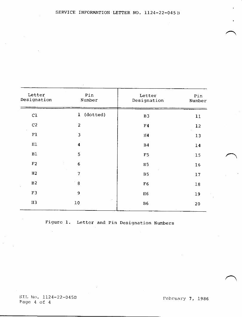
SERVICE INFORMATION LETTER NO. LL24.22-0458
LetterDesignation
c1
c2
F1
H1
B1
F2
H2
B2
F3
H3
SrL No. LL2.4-22-0458Page 4 of 4
I (dotted)
2
3
4
5
6
7
I
9
10
LetterDesignation
B3
F4
H4
B4
F5
H5
B5
F6
H6
B6
PinNumber
II
T2
13
I4
15
I6
T7
18
19
20
PinNumber
Figure 1. Letter and pin Designation Numbers
[cbruary 7, 1986
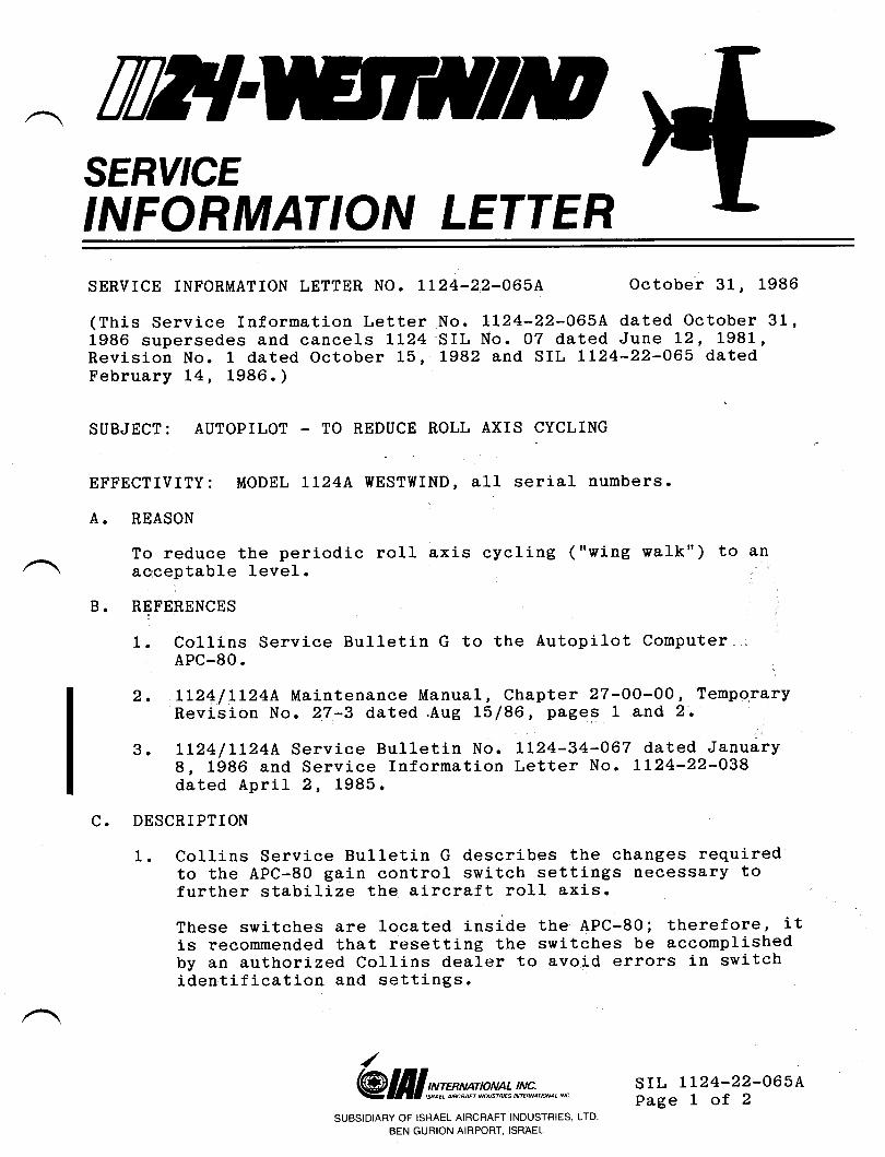
TilT{SERY'CEINFORMATION LETTERSERVICE INFORMATION LETTER NO. lL24-22-065A October 31, 1986
(This Service Information Letter No. LL24-22-065A dated October 311986 supersedes and cancels LL24 SIL No. 07 dated June L2, 1981,Revision No. 1 dated October 15, L982 and SIL 1124-22-065 datedFebruary 14, 1986. )
SUBJECT: AUTOPILOT TO REDUCE ROLL AXIS CYCLING
EFFECTIVITY: MODEL LL24A WESTWIND, all serial numbers.
A. REASON
To reduce the periodic ro11 axis cycling ( "wing walk" ) to anacceptable level.
REFERENCES
1, Collins Service Bulletin G to the Autopilot ComputerAPC-80.
2. LL24/LI24A Maintenance Manual, Chapter 2?-00-OO, TemporaryRevision No. 27-3 dated .Aug 15/86, pages 1 and 2.
3. IL24/IL24A Service Bulletin No. Ll24-34-067 dated January8, 1986 and Service Information Letter No. LL24-22-038dated April 2, 1985.
C. DESCRIPTION
1. Collins Service Bulletin G describes the changes requiredto the APC-80 gain control switch settings necessary tofurther stabiLize the aircraft ro11 axis.
These switches are located inside the APC-80; therefore, itis recommended that resetting the switches be accomplishedby an authorized Collins dealer to avoid errors in switchidentification and settings.
/
@ III st'mp**,: lt!*.,*,* srL LL24-22-065APage 1 of 2
B.
SUBSIDIARY OF ISRAEL AIRCRAFT INDUSTRIES, LTD
BEN GURION AIRPORT, ISRAEL
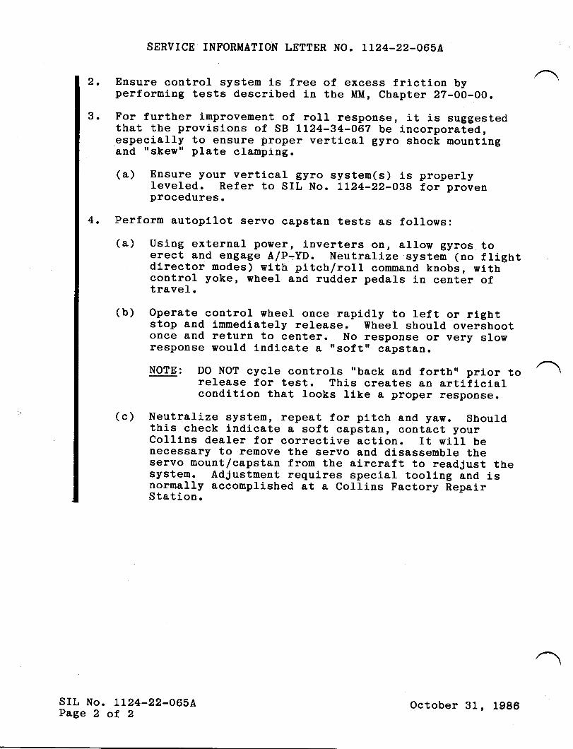
SERVICE INFORMATION LETTER NO. LL24-22-O65A
Ensure control systen is free of excess friction byperforming tests described in the MM, Chapter 22-00-00.
For further improvement of rorl response, it is suggestedthat the provj.sions of SB LL24-34-O67 be incorporated,especially to ensure proper verti-cal gyro shock mountingand "s.kew" plate clamping.
(a) Ensure your vertical gyro system(s) is properlyleveled. Refer to SIL No. LLZ4-22-038 for provenprocedures.
Perform autopilot servo capstan tests as follows:(a) Using external power, i.nverters otr, allow gyros toerect and engage A/P-YD. NeutrarLze system (no flightdirector modes) with pitch/roll command knobs, withcontrol yoke, wheel and rudder pedals in center oftravel.(b) Operate control wheel once rapidly to left or rlght
stop and immediately release. wheel should overshootonce and return to center. No response or very slowresponse would indicate a ,,soft', c&pstan.
NOTE: DO NOT cycle controls "back and forth,' prior torelease for test. This creates an artificialcondition that looks like a proper response.
(c) Neutralize system, repeat for pitch and lBWo Shouldthis check indicate a soft capstan, contact yourCollins dealer for corrective action. It will benecessary to remove the servo and disassemble theservo mount/capstan from the aircraft to readjust thesystem. Adjustment requires special tooling and isnormally accomplished at a Collins Factory RepalrStation.
2.
3.
4.
SIL No. LL24-22-065APage 2 of 2
October 31, 1986
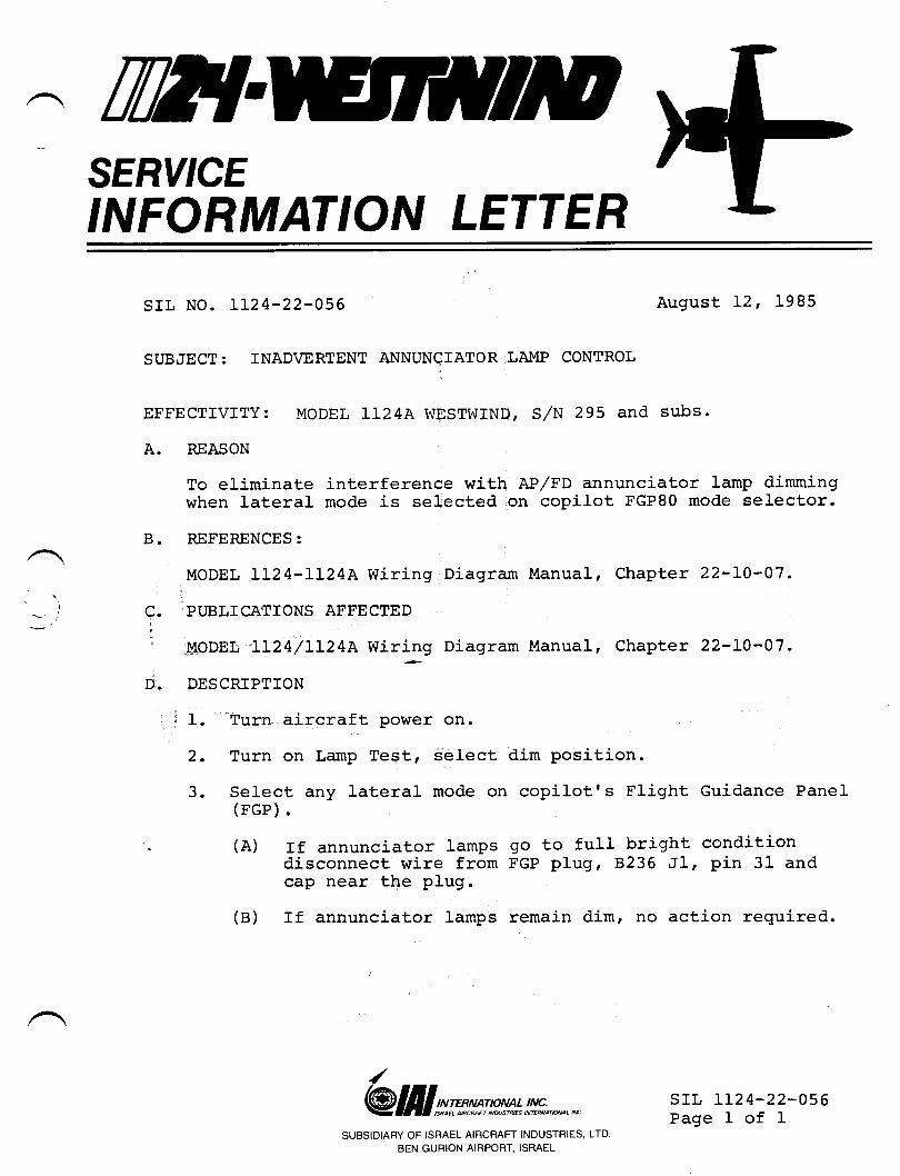
TWISERY'CEINFORMATION LETTER
SIL No. LL24-22-056 August L2, 1985
SUBJECT: INAD\ERTENT AItrNUNCIATOR LAIvIP CONTROL
EFFECTIVITY: MODEL LI24A WESTWIND, S/N 295 and subs.
A. REASON
To eliminate interference with AP/FD annunciator lamp d,immingwhen lateral mode is selected on copilot FGP80 mode selector.
B. REFERENCES:
MODEL IL24-LL24A Wiring Diagram Manual, Chapter 22-LO-07.
C. PUBLTCATIONS AFFECTED
MODEL LI24/LL24A Wiring Diagram Manual, Chapter 22-LO-07.
D. DESCRIPTION
1. Turn aj-rcraft power on.
2. Turn on Lamp Test, select
3. Select any lateral mode on(FGP).
- (A) rf annunciator lamPsdisconnect wire fromcap near the plug.
(B) If annunciator lamps
dim position.
copilot's Flight Guidance Panel
go to full bright conditionFGP plug, 8236 Jl, pin 31 and
remain dim, no action required.
/
@ III wmsp*** lt#;,*,*SUBSIDIARY OF ISRAEL AIRCRAFT INDUSTRIES, LTD
BEN GURION AIRPORT, ISRAEL
srr, LL24-22-056Page I of 1
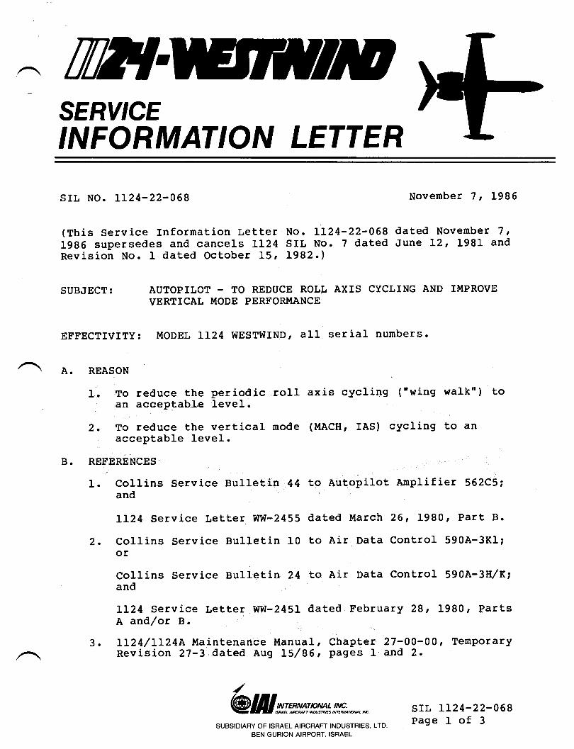
TilT{SERY'CEINFORMATION LETTER
SIt NO. LL24-22-0Gg November 7 t 1986
(This service Information Letter No. LL24-22-068 dated Novenber 7 tf9g6 supersedes and cancels LL24 SIL No. 7 dated June L2, 1981 andRevision No. I dated October 15r 1982.)
SUBJECT:
EFFECTIVITy: Ir{ODEt LL24 WESTWIND, all serial numbers.
AUTOPILOT - TO REDUCE ROLL AXIS CYCLING AND IMPROVEVERTICAT MODE PERFORMANCE
A. REASON
l. To reduce the periodic rollan acceptable level.
2. To reduce the vertical modeacceptable level.
REFERENCES
I. Collins Service Bullet,in 44and
LL24 Service Letter ww-2455
2. Collins Service Bulletin 10
axis cycling ("wing walkn) to
(MACH, IAS) cycling to an
to Autopilot Anplifier 562C5i
dated March 261 1980r Part B.
to Air Data Control 590A-3K1;
B.
or
Collins Service Bulletin 24 to Air Data Control 590A-3H/K;and
LL24 Service Letter WW-245I dated February 28 t 1980, PartsA and/or B.
3. LL24/IL24A llaintenance Manual, Chapte r 27-00-0Ot TemporaryRevision 27-3 dated Aug L5/85, Pages 1 and 2.
/
@frlwwm+!,!!*.,*.,n srL LL24-22-068Page I of 3
SUBSIDIARY OF ISRAEL AIRCRAFT INDUSTRIES, LTD.
BEN GURION AIRPORT. ISRAEL
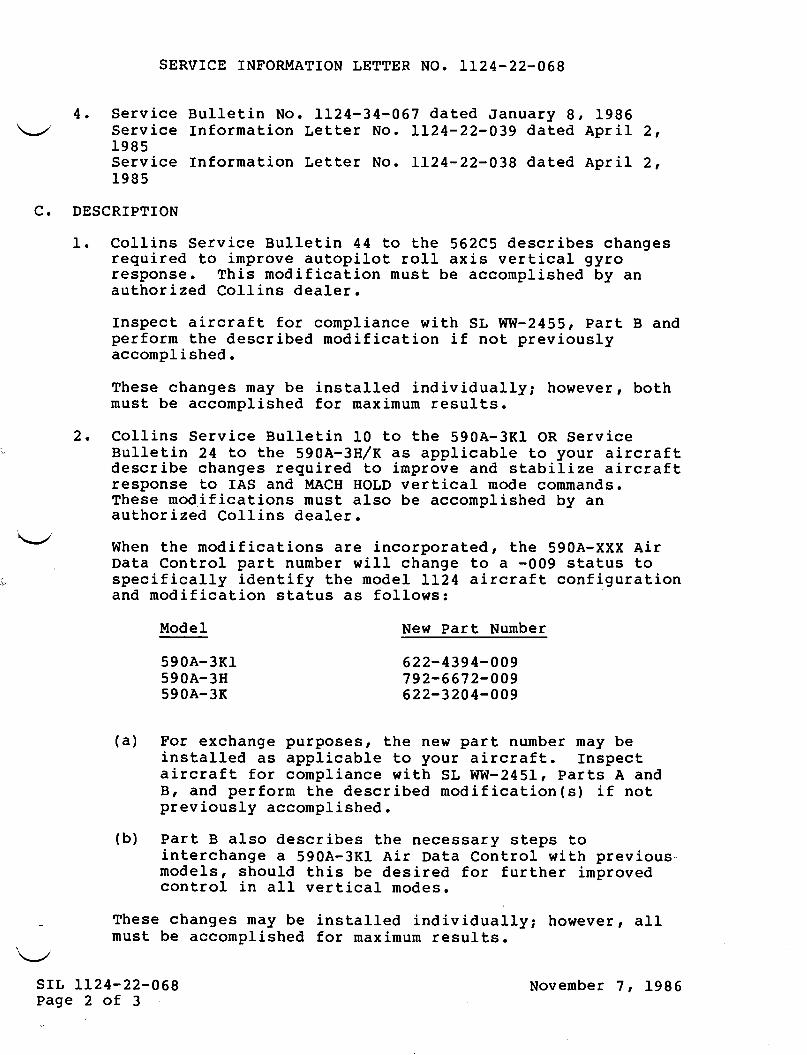
.sepou TPcTl.raA TTP UT TOrlUoCpaAoJduT :aql.rnI ro] parTsap aq sTqt pTnoqs ,slapou
-snoTaa:d qlTer TorluoC eleq rTv Txt-v065 p abueqcralul01 sdals f,:essacau aql saqT.rcsap osTE g lrpd (q)
. paqsTlduocce .{lsnolaardlou JT (s)uorlecrJTporu paqTrcsap aqt u:oErad pup ,g
pue v s?.rpd 'Tgtz-uu ts r{?Tt acuellduroc f,oJ ltprcrTplcadsul '?JprcrTp rnor( o1 alqecrldde sp paTTelsuraq .{eu raqunu 1:ed arau aql ,sesod:nd a6ueqcxa rod (e)
986T t L raquaAoN
'slTnsar unurTxPur foJTTe , raaauoq !tr11enp1ATpuT paTTe?suT
600-?0zg -7,29600-2199-Z6L60 0 -?6t? -zz9
'Z TTrdv palpp geO-ZZ-tZTT .oN rallaT
'Z TTrdv patpp 680-ZZ-?ZTT .oN relteT986T ,8 F:Bnuef palPp Lgo-tE-?zTT
paqsTldtuocce aq lsnuraq feu se6ueqc asaql
xt-v069Ht-v059
TXt-V069
g Jo 7 a6ea890-72-vzTI Trs
NOr&drucssc'c
s86TacT Aras
s86TecT
^ras acT AJas
raqurnN lred naNTapoll
3sAoTToJ Se Snle?S uOTlecTJTpolu pupuollern6r;uoc l;prcrTp V?,TI Tapou aql {lTf,uapT Allecrylcads
o? sn?p1s 600- e ol a6ueqc TTTI{ raqunu l:ed Torluo3 elpotTv xxx-vo6s aq1 'pa?e:od.rocuT arp suoTlpcTJrpour eq1 uaru,t
'raTeep surTToc pazT:oqfnPue .{q paqsTldurocce aq osTe lsnu suoTlecTf Tpour esaq,tr
.spuerrruoc apou TecT?.raA qToH Hcvl{ pup svr 01 asuodsarlJef,crTp azTTTqe?s pue aaordul ot parlnba: sa6ueqc aqrrcsap?Jp.rc.rTp :noI o1 alqecrldde sE x/H€-v06E aql 01 VZ ur?aTTng
acTAras uo Tlt-v069 aql 01 0T urlaTTng ecT^ras suTTToc
's?Tnsar unurxeu roJ paqsTldtuocce aq lsnuqloq 'raaaaroq J^{TTenpTATpuT paTTE?suT aq Feu sa6ueqc osaqJ,
'paqsTldruoccedlsnoraerd 1ou lT uoTlpcTJTpolu peqT:csap aql urotr:ad
pue g ?rpd '99?z-Ml{ Ts r{1Tlr acuprlduoc roJ l}prcrTe lcadsul
'faTpap suTTToc pazTroqlneue ,{q paqsTldruocce aq ?snu uoTf,pcTJTpour sTr{,1 .asuodse.l
o:16 TpcTl.roA sTxp TTor 1o11do1ne aao:dulr 01 pargnba:sa6ueqc saqTf,csap gCggg aq1 01 VV urlaTTng acrAras suTTToJ
'z
.T
uoTlPlrrf oJiuI
uorlPurotrur'oN uTlaTTng't
B90-Z,Z-VZTI'ON Ug,tr,tgT NOr,IVWUO.INr gCrAUgS
(a)
(b)
3.
4.
SERVICE INFORMATION TETTER NO. LL24-22-068
Ensure control system is free of excess friction byperforming tests described in Maintenance lrlanual Chapter27-00-00.
For further improvement of roll response, it is suggestedthat the provisions of SIL No. LL24-22-039 and SB No.LL24-34-057 be incorporated. This modification will alsoreduce altitude loss (when in ALT IIOLD or ALT TRACK ruodes)during high roll bank angles.
(a) Ensure your vertical gyro systen(s) is properlyleveled. Refer to SIL No. LL24-22-038 for provenprocedures.
5. Perform autopilot servo capstan tests as follows:
Using external po!"er, inverters on, allow gyros toerect and engage A/p-yo. Neutralize systen (no flightdirector modes) with pitch/roll command knobs, withcontrol yoke, wheel and rudder pedals in center oftravel.
Operate control wheel once rapidly to left or rightstop and immediately release. lfheel should overshootonce and return to center. No resPonse or very slowresponse would indicate a "soft" capstan.
NOTE: DO NOT cycle controls "back and forth" prior torelease for test. This creates an artificialcondition that looks like a proper response.
(c) Neutralize system, repeat for pitch and yaw. Shouldthis check indicate a soft capstan' contact yourCollins dealer for corrective action. It will benecessary to remove the servo and disassemble theservo nount,/capstan from the aircraft to readjust thesystem. Adjustment requires special tooling and isnormally accomplished at a Collins Factory RepairStation.
srL LL24-22-068Page 3 of 3
Novenber 'l t 1986
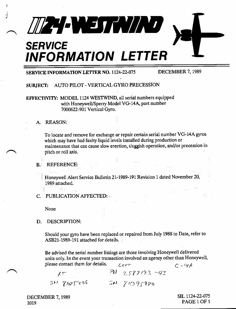
'lI-r ttflSERY'CEINFORMATION LETTER
SERVICE INFORMATION LETTER NO. LL24.22-075 DECEMBER 7, 1989
SUBJECT: AUTO PILOT - VERTICALGYRO PRECESSION
EFFECTMTY: MODELLL}4 WESTWIND, all serial numbers equippedwith HoneywelVsperry Model VG-14A' part number7 000622-90 1 Vertical Gyro.
A REASON:
To locate and remove for exchange or repair certain serial number VG-14A gyros
which may have had faulty liquid levels installed during production ormaintenance that can cause slow erection, sluggish operation, and/or precession inpitch or roll axis.
B. REFERENCE:
Honeywell Alert Service Bulletin 2L-L989-lgl Revision 1 dated November 20,
1.989 attached.
C. PUBLICATIONAFFECTED:
None
D. DESCRIPTION:
Should your Srro have been replaced or repaired from July 1988 to Date, refer toASB21-1989-19 1 attached for details.
Be advised the serial number listings are those involving Honeywell deliveredunits only. In the event your transaction involved anagenq other than Honeywell,please contact them for details. LE r-
f-r 7P LTtr 7 r? \ *4s
5)i VhTf-zo6 3o, YtOJ;9"o
DECEMBER 7, 1989
1019
C _1,/A
stLtl24-22-075PAGE 1OF 1
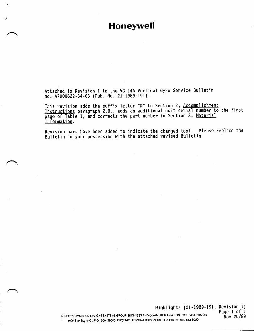
Honeywell
Attached is Revision I to theNo. A7000622-34-03 (Pub. No.
This revision adds the suffixInstructions paragraph 2.8.,page of Table I, and correctsI nformat i on .
Revision bars have been added to indicate the changed text. Please replace theBul I eti n i n your possess'ion w'ith the attached revi sed Bul I eti n.
Highl ights (21-1989-l9l' Revision -l)- Pagelofl**::::HTffi'fl::'ffH::i:::J,:iil?.Tffi'::;",il:]#3#','o* ilov 20l8e
VG-l4A Vertical Gyro Serv'ice Bulletin2l-1989-l9l).
letter "K" to Section ?, Accomolishmentadds an additional unit serial number to the firstthe part number in Section 3, Material
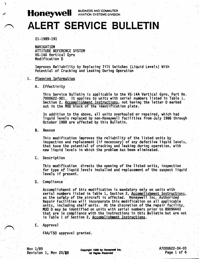
,!l Honeywell trili'Aii#?'"f$f,V[:3,.
2r-1989-l9l
NAVIGATIONATTITUDE REFERENCE SYSTEM
VG-l4A Vertical Gyrol,lodification D
Improves Reliability by Replacing Tilt Switches (Liquid Levels) ltithPstential of Cracking and Leaking 0uring 0peration
l. Planninq Infgrmation
A. Effectivity
This Service Bul]etin is applicable to the VG-I4A Vertical Gyro, Part No.7000622-901. It applies to units with serial numbers listed in Table l,Section 2, Accpmqlishment Instructions, not having the letter D markedout in the M00 block of the identification plate.
In addition to the above, all units overhauled or repaired, which hadliquid levels replaced by non-Honeywell facilities from July 1988 throughOctober 1989 are affected by this Bulletin.
B. Reason
This modification improves the reliability of the listed units byinspection and replacement (if necessary) of any defective liquid levels,that have the potintial of cracking and leaking during operation, withnew liquid levels in which the problem has been eliminated.
C. Description
This modification directs the opening of the listed units, inspectionfor type of liquid levels installed and replacement of the suspect liquidIevels if present.
D. Compl iance
Accomplishment of this modification is mandatory only on units withserial numbers listed in Table l, Section 2, Accomplishqeni, Instruqtions,as the safety of the aircraft is affected. Honeywell Inc. AuthorizedRepair Facfllties will incorporate this.modification on all applicableunits, including shelf units. At the discretion of the repair faci'lity,t'l0D 0 may be identified on units with serial numbers prior to 89096443that are in conrpliance with the instr"uctions in this Bulletin but are notin Tab'le I of Section 2, AcgomoliFhment Instructions.
E. Approval
FM/TSO approval granted.
Nov 1189Revision l, Hov 20/89
Cmfidil tgm tf rb||.rnl lnA[ R!fit! nem,cd
A7000622-34-03Page I of 6
Honeywell iV'1i,3i,'S?ffS$,Vffi3-
SEHVICE BULLETIN
l. F. Manpower
This modification may be accomplished and unit tested in apBroximately7.0 man-hours. t.lhen this modification is performed concumently withother repa'ir and testing operations, approximately 3.0 man-hours arerequi red.
G. Material - Cost and Availability
Parts and materials required to accomplish the modification described inthis Bulletin are available from Honeywell Inc. Refer to Section 3,Material Information, for part numbers, part descriptions., and orderingi nformati on.
Fl. Tool i ng - Pri ce Avai I ab'i I i ty
No special equipment is required to accomplish the work described in thisBulletin.
r I. lleight and Balance
No change.
J. Electrical Load Data
Not affected.
K. References
(l) Required to perform this Bulletin.
Component Maintenance Manual (Clm), Pub. No. 09-3224-02, dated IJune 1979r r€vised I t'larch 1981.
(2) Used as source information for this Bulletin. (Not required to i
perform the Bulletin.)
Engineering Drawing No. 7000622, Revision K.
L. Other Publ icat'ions Affected
Component l'laintepance l,lanual, Pub. No. 09-3224-02, will be revised as aconsequence of tlris Bulletin. Testing is not affected.
r"
Coefigttt 1989 by lloeWrai haAll filgt{s nccanFd
47000622-34-03Page 2llov l/89
1-
,^
Honeywell lVili3i,'#?'TJ$,YL''3*
SERVICE BULLETIN
2. Accomnlishment Instructions
A. Gain access to the Ilquid levels (240, IPL Figure 3 and 70, IPL Figure 4)by accompl ishing DISASSET'I8LY paragraphs 3.A. (l) through B. (l), uslng CMt'l
(References l.K.(1)).
B. Inspect liquid levels referenced in paragraph 2.A. of this Eulletin. Ifthe liquid levels have serial numbers beginning with the letters nEGn orit is obscured so that identification is not possible, proceed toparagraph 2.C. If the levels have serial numbers beginning with theletter nSo or ending with the letter "Kn proceed to paragraph 2.0.
C; Replace the liquid levels referenced in paragraph 2.A. of this Eulletinin accordance with procedures in REPAIR paragraph 3.0.(3) using Clll,l(References 1.K. (l)).
D. Assemble unit in accordance with ASSEI|BLY paragraphs 3.E.(l) through (22)using Cl.lll' (References l.K.(1)) as needed, and paragraphs 5.A. and B.
E. l'lark out the letter D in the VG-I4A Ver:tical Gyro identification plate.
F. Test the VG-I4A Vertical Gyro in accordance wlth References l.K.(l).
Nov 1/89Revision I, l{sv 20i^89
Aaptrielf tfOe by ttg|rrrf hcAil Rgtlt Rrs{rd
A70As622-34-03Page 3
n
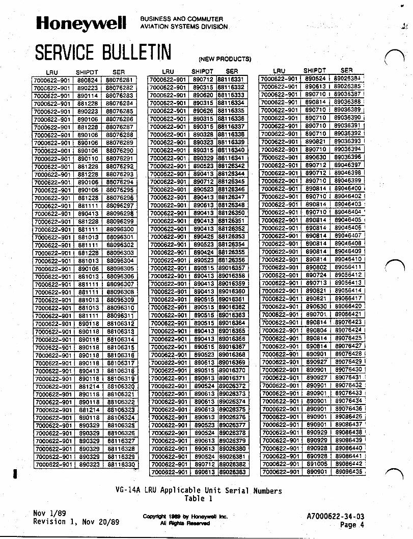
Honeywell iV,Xi3i,'#?,?Yfil'f3''.
SERVICE BULLETINLRU
*t
SHIPOT SER7000622-901 880824 88076281700c622-901 890223 880762827000622-901 8901 14 880762837000622-901 881228 880762847000622-901 890223 880762857000622-901 890106 880762867000622-901 881228 880762877000522-901 890106 880762887000622-901 8901 06 880762897000622-901 890106 880762907000622-901 8901 10 880762917000622-901 881 228 880762927000622-901 881228 880762937000622-901 8901 06 880762947000622-901 8901 06 880762957000622-901 881228 880752967000622-901 881111 880962977000622-901 89041 3 880962987000622-901 88',t228 880962997000622-901 881111 880963007000622-901 881 01 3 880963017000622-901 881111 880963027000622-901 881 228 880963037000622-901 881013 880963047000622-901 890106 880963057000622-901 881 01 3 880963067000622-901 881111 880963077000622-901 881111 880963087000622-901 881 01 3 880963097000622-901 881 01 3 8809631 07000622-901 881111 88096317000622-901 8901 1 8 881 0631
7000622-901 8901 1 8 881 0631 37000622-901 8901 1 8 881063147000622-901 8901 18 881 0631 57000622-901 8901 18 881 0631 67000622-901 8901 1 I 881063177000622-901 89041 3 881 0631
7000622-901 8901 1 8 881 0631 I7000622-901 881214 881 0632r
7000622-901 8901 1 8 881 063217000622-901 8901 18 88r063227000622-901 8812't4 881063237000622-901 8901 18 881063247000622-90r 890329 881063257000622-901 890329 881063267000622-901 890329 881 163277000622-901 890329 881 1 63287000622-901 890329 881 1 63297000622-901 890323 881 1 6330
(NEW PROOUCTS)
SHIPDT SER7000622-901 890712 881 16331
7000622-901 890315 B8r 163327000622-901 890020 881 163337000622-901 890315 881 r 63347000622-901 890626 88116i13s
7000622-901 890315 881r63357000622-901 890315 881163377000622-90r 890328 881163387000622-901 890323 881 163397000622-901 890315 881 163407000622-901 890329 881 16341
7000622-901 890523 881263427000622-901 890413 881263447000622-901 890712 881263457000622-901 890523 38r263467000622-901 890413 ,$243477000622-901 89061 3 38126348
7000622-901 890413 88126350
7000622-901 890.t13 881 26351
7000622-901 890413 881263527000622-901 890425 881263537000622-901 890523 981263547000622-901 890424 881263557000622-901 890523 881263567000622-901 890515 890163577000622-90r 890413 890163s87000622-901 890413 t901 53s97000622-901 890413 t90163607000622-901 890515 t9016361
7000622-901 89051 s 39016362
7000622-901 890515 t901dt637000622-901 89051 5 39016:t64
7000622-90r 890413 39016365
7000622-901 890413 39016366
7000622-901 890515 390163877000622-901 890s23 39016368
7000622-901 890613 39016369
7000622-901 89051 5 39015370
7000622-901 890613 890r63717000522-901 890524 89026372700Q622-901 890613 990263737000622-901 890613 890263747000622-901 890613 890263757000622-901 890613 890263767000622-90r 890s23 890263777000622-901 890524 890263787000622-901 89061 3 89026379700062-901 890613 890263807000622-901 890524 89026381
7000622-901 890712 3S0283827000522-901 890613 t9026383
SHIPOT SEN
7000622-901 890710 89036387 |
890710 89036389
89036392 I
89036393 |
890363968904639789046398 |
89046400890710 89046402 !
7000622-90r 890814 89046403 I
89046404 |
89046405 i
89081 4 89046406 |
8904640889046409
890814 89046410 |
8905641 1
890724 89056412 I
7000622-901 | 890713 89056413 |
89082r 89056414 |
g9g55c20 i
7000622-901 89076423 i
7000622-901 890804 89076424 |
890764278907642889076429 |
89076430
89076432 I
89075433 i
8907647000622-901 890901 89076436 i
89086426 i
7000622-901 890901 89086437 i
89085438 I
89086439 |
89086440890928 89086441 i
890864d2 :
89096d35 ,
47000622-34-03Page 4
n
Nov 1/89Revision l, Nov 20189
VG-l4A LRU Applicable Unit SeriaI ilumbersTable I
Copydettr 1$9 by llotrsyd nc.ff nfi3 Fcan,€d
7000622-901
7000622-9017000622-901
890710 | 890363947000622-901
7000622-9017000622-9017000622-901
7000622-901 | 890814
7000622-9017000522-901
7000622-901
7000622-901 I 8909297000622-901 | 890929
7000622-901 I 891005
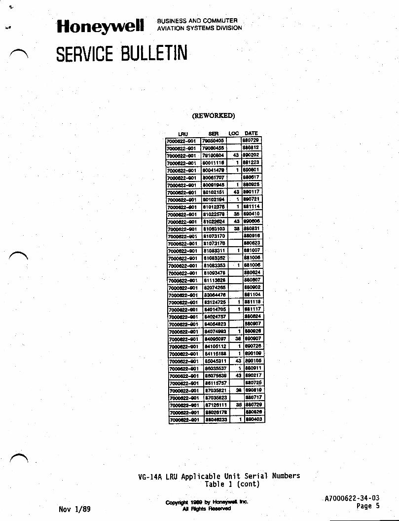
*' Honeywell :Viii3i,'S?'"'3y'$,Vffi3-
SERVICE BULLETIN
(REWORKED)
LRU , 8ER LoC D TE
7000412-001 t9050405 880720
700@2-eol 79060155 88{1812
70fl)Gt2-€01 7010O80.f ,|iJ 890202
t(xxl|al-to1 8(Fr1fiC I nlztg70006:12-801 800a1{7e I Bgt80l
7(xXt6ill.{0r crcorTqt Nst617
7000d12-f01 8o0ete45 t 880025
7000€2-{01 80r0215t .til mot17
70006i12-st mt02l94 1 !e0721
70qxxa-e0r 8r01237t t t81114
7000cxl-0ol 81ocafl4 35 Ngo4i0
r0o0@41 Bl0Zt@4 € 890606
lo{rocdtrgol 81oGltqt 38 880831
7000GP-e0l 8't073170 8t&ll67000d12-0ot 810?3176 880€23
7@1 8108:]311 1 t81007
7000€2-e0l tro833tn nr00670q,G22-€Ol 8108Cr53 1 B8t(p3
7000d2.€01 81093478 t8062.1
7000@-€01 81 r 13488 880G07
7000c42-eol e2o71Xg5 t80002
7000e!2-e01 830041.76 881l0.l
70m@-,sol 83,.2(n5 1 181 | 18
/000dl2-e0i 8a0r{706 I t8r1t7/000QP-e0l utna76;' t80624
t00ol]2!l.St tao5a823 Btoeo7
r000dl24l 8407199i1 I l80e2c
7000G12-€01 8a0t50c7 36 &0e07
7000d12-e0l 84105112 t 8e0726
7000GP-e01 84r15t88 I 800109
70np,trA2-g|1 850453fi /K 8e0t05
7000cl2-eot 860355it7 t 380ei I70o0dl2-001 86075fft0 .13 t902t7
[email protected] 8611s'st 180725
t0o0fiIl-gol 870:158:11 38 8908t9
l000qn-eot 87035823 g8i071v
7000i'z2401 e71261'tl 35 l/&'72A
7000(2-00t 8802t178 t8082C
/60t4t{01 Sdttdl3il I t00ao3
Copydslr l0€9 !Y l{mryuef haAl Sglils Re.ottt€d
A7000622-34-03Page 5
VG-14A LRU Applicable Unit Serial NumbersTable I (cont)
n
tlov l/89
Hon iViiiSi,'#'i',?Y$'VE:3-
SERVICE BULLETIN
3. Material Information
The following parts are required to modify each VG-I4A Vertical Gyro inaccordance with this Bulletin,:
New Part No. Qty 0escription
I 4020077 2 Sttitch,-Ilt (!riggi{ Level)(FSC!.| 55939, PN 077)
For pricing and additional information, please contact:
Honeywell Inc.Sperry Comercial Flight Systens Group1830 Industrial Avenuettichita, Kansas 67216
ATTN: Replacement Parts
TEL: (316) s22-8t72TLX: 417-444FAX: (315) 522-26s3
t{ov l/8e *t*n$#ff$.. * A7000622-34-03Revision l, Nov 20/89 -- elnru-nslrid Page 6
H
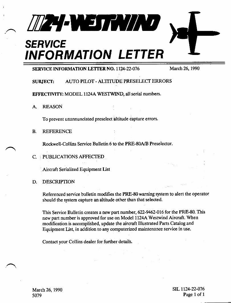
TilEISERY'CEINFORMATION LETTER
SERVICE INFORMATION LETTER NO. IIVI-22-W6 March 26,L990
SUBJECT: AUTO PILOT - ALTITUDE PRESETBCT ERRORS
EFFECTMTY: MODF,L LI?4AWESTWIND, all serial numbers.
A REASON
To prevent unannunciated preselect altitude capture errors.
B. REFERENCE
Rockwell-Coltins Service Bulletin 6 to the PRE-80A8 Preselector.
C. PUBLICATIONSAFFECTED
Aircraft Serialized Equipment List
D. DESCRIPTION
Referenced service bulletin modifies the PRE-80 warning system to alert the operatorshould the system capture an dtitude other than that selected.
This Service Bulletin creates a new part number,622-9462-016 for the PRE-80. Thisnew part number is approved for use on Model LLz4[Westwind Aircraft. Whenmodification is accomplished, update the aircraft lllustrated Parts Catalog andEquipment List, in addition to any computerized maintenance service in use.
Contact your Collins dealer for further details.
March 26,19905079
srL Lr24-22-076Page 1 of 1
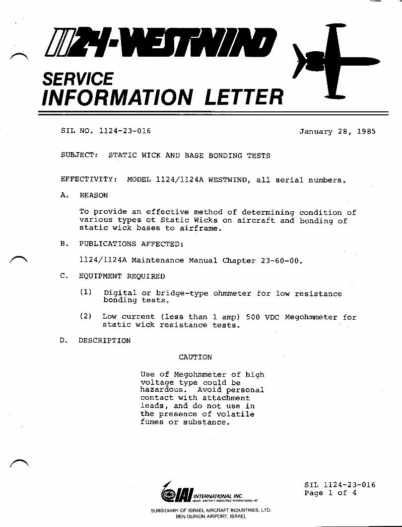
TWISERY'CEINFORMATION LETTER
SIL NO. LT24-23-OL6
SUBJECT: STATIC WTCK AND BASE BONDING TESTS
January 28, 1985
EFFEcrrvrrY: MODEL LL24/LL24A wEsrwrND, all serial numbers.
A. REASON
To provide an effective method of determining condition ofvarious types ot static wicks on aircraft and bondinq ofstatic wick bases to airframe.
B. PUBLICATTONS AFFECTED:
1L24/LL24A Maintenance Manual Chapter 23-60-00.
C. EQUIPMENT REQUIRED
(1) Digital or bridge-type ohmmeter for 1ow resistancebonding tests.
(2) Low current (less than 1 amp) 500 VDC Megohmmeter forstatic wick resistance tests.
D. DESCRIPTION
CAUTION
Use of Megohmmeter of highvoltage type could behazardous, Avoid personalcontact with attachmentleads, and do not use inthe presence of volatilefumes or substance.
/@ lI I srms tp*n :,!n!#., *,, n
SUBSIDIARY OF ISRAEL AIRCRAFT INDUSTRIES, LTD.
BEN GURION AIRPORT, ISRAEL
srL IL24-23-0r6Page 1 of 4
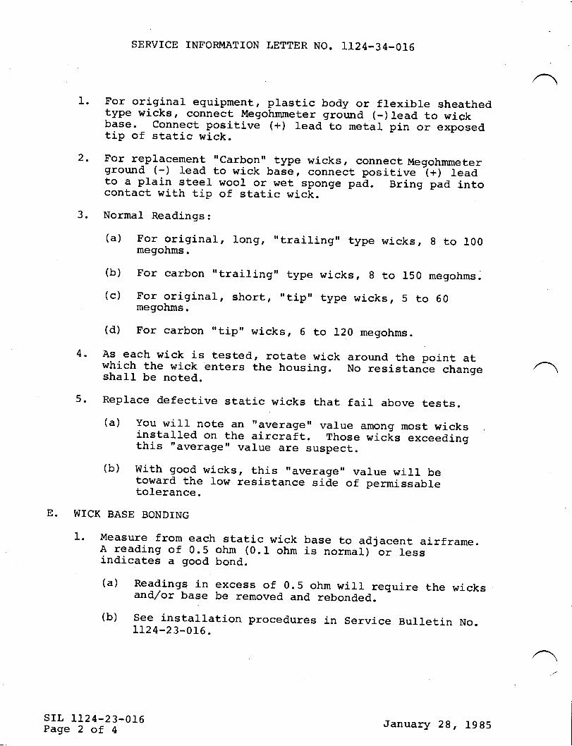
SERVTCE INFORMATION LETTER NO. T124-34-016
1. For originar equipment, prastic body or flexibre sheathedtype wicks, connect Megohmmeter ground (-)lead to wickbase. connect positive (+) lead to metal pin or exposedtip of static wick.
2. For replacement "carbon" type wicks, connect Megohmmeterground (-) lead to wick base, connect positive -(+) leadto a plain steer wool or wet sponge pad. Bring pad intocontact with tip of static wick.3. Normal Readings:
(a) For original, long, ',trai1ing,, type wicks, 8 to 100megohms.
(b) For carbon "trailing,' type
(c) For original , short , ,'tip',megohms.
(d) For carbon "tip', wicks, 6
wicks, 8 to 150 megohrns.
type wicks, 5 to 50
to 120 megohms.
4. As each wick is tested, rotate wick around the point atwhich the wick enters the housing. No resistanle changeshall be noted.
5. Replace defective static wicks that fail above tests.(a) you will note an "averager, varue among most wicksinstalled on the aircrait. Those wicfs exceedingthis "average" value are suspect.(b)
I*:,3":f,.'i:1";":*;J::.:i3: ";"#:*I::1ri:t,olerance.
E. WTCK BASE BONDING
1. Measure from each static wick base to adjacent airframe.A reading of 0.5 ohm (0.1 ohm is normal)-or lessindicates a good bond.
(a) Readings in excess of 0.5 ohm will require the wicksand/or base be removed and rebonded.
(b) See installation procedures in Servj-ce BuLletin No.IL24_23_016.
srl, 1124-23-016Page 2 of 4
January 28, 1985
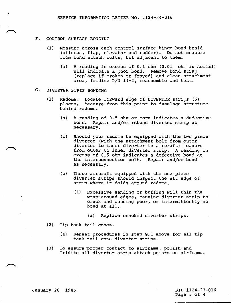
SERVICE INFORMATION LETTER NO. LI24-34-016
F. CONTROL SURFACE BONDING
(1) Measure across each control surface hinge bond braid(aileron, flap, elevator and rudder). Do not measurefrom bond attach bolts, but adjacent to them.
(a) A readj.ng in excess of 0.I ohm (0.01 ohm is normal)will indicate a poor bond. Remove bond st,rap(replace if broken or frayed) and clean attachmentarea, Iridite P/N L4-2, reassemble and test.
G. DTVERTER STRIP BONDING
(1) Radome: Locate forward edge of DIVERTER strips (6)places. Measure from thie point to fuselage structurebehind radome.
(a) A reading of 0.5 ohm or more indicates a defectivebond. Repair and/or rebond diverter strip asnecessary.
(b) Should your radome be equipped with the two piecediverter (with the attachment bolt from outerdiverter to inner diverter to aircraft) measurefrom outer to inner diverter strip. A reading inexcess of 0.5 ohm indicates a defective bond atthe interconnection bolt. Repair and/or bondas necessary.
(c) Those aircraft equipped with the one piecediverter strips shouLd inspect the aft edge ofstrip where it folds around radome.
(1) Excessive sanding or buffing will thin thewrap-around edges, causing diverter strip tocrack and causing poorr or intermittently nobond at all.(a) Replace cracked diverter strips
(2) Tip tank tail cones.
(a) Repeat procedures in step G.1 above for all tiptank tail cone diverter strips.
(3) To ensure'proper contact to airframe, polish andIridite all diverter strip attach points on airframe.
srl, LL24-23-016Page 3 of 4
January 28, 1985
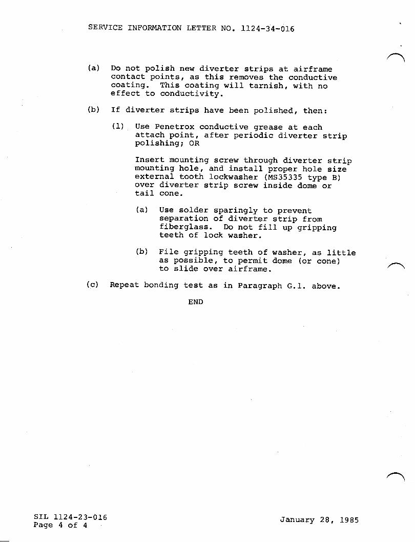
SERVICE INFORMATTON LETTER NO. IL24-34-016
(a) Do not polish new diverter strips at airframecontact pointsr ES this removes the conductivecoating. This coating will tarnish, with noeffect to conductivity.
(b) If diverter strips have been polished, then:(1) Use Penetrox conductive grease at each
attach point, after periodic diverter strippolishing; OR
Insert mountj-ng screw through diverter stripmounting hole, and install proper hole sizeexternal tooth lockwasher (MS35335 type B)over diverter strip scre$r inside dome ortail cone.
(a) Use solder sparingly to preventseparation of diverter strip fromfiberglass. Do not fill up grippingteeth of lock washer.
(b) File gripping teeth of washer, as 1ittleas possible, to permit dome (or cone)to slide over airframe
(c) Repeat bonding test as in paragraph G.1. above.
srr, IL24-23-016Page 4 of 4
January 28, 1985
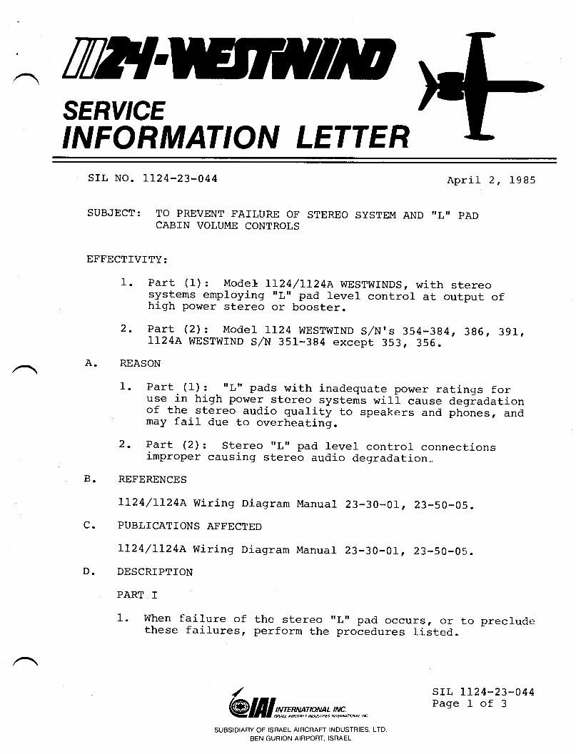
IWTSERY'CEINFORMATION LETTER
srr, No. 1124-23-044 April 2, 1985
SUBJECT: TO PREVENT FATLURE OF STEREO SYSTEM AND IILII PADCABTN VOLUME CONTROLS
EFFECTIVTTY:
1- Part (1): Mode} rL24/rr24A WESTWTNDS, with stereosystems employing rrl," pad level contror at output ofhigh power stereo or booster.
2- Part (2)z Model rL24 wEsrwrND s/n's 354-384, 386, 391,1I24A WESTWTND S/N 351-394 except 353, 355.
A. REASON
l-- Part. (1]: - "L" pads with inadequate power ratings foruse in high power. stereo systems wj-1i cause degiadationof the stereo audio quality to speakers and phones, andmay fail due to overheating.
2. Part (2) z stereo rrl.rr pad level contror connectionsimproper causing stereo audio degradation.
B. REFERENCES
LL24/LL24A wiring Diagram Manual 23-30-01, 23-50-05.
C. PUBLTCATIONS AFFECTED
rL24/lr24e wiring Diagram Manual 23-30-01, 23-50-05.
D. DESCRIPTION
PART I
1. when failure of the stereo rrl.'pad occurs, or to precludethese failures, perform the procedures listed.
/@lfllsrmse*n*!#;,*^,*
SUBSIDIARY OF ISRAEL AIRCRAFT INDUSTRIES, LTDBEN GURION AIRPORT, ISRAEL
srl, LI24-23-044Page I of 3
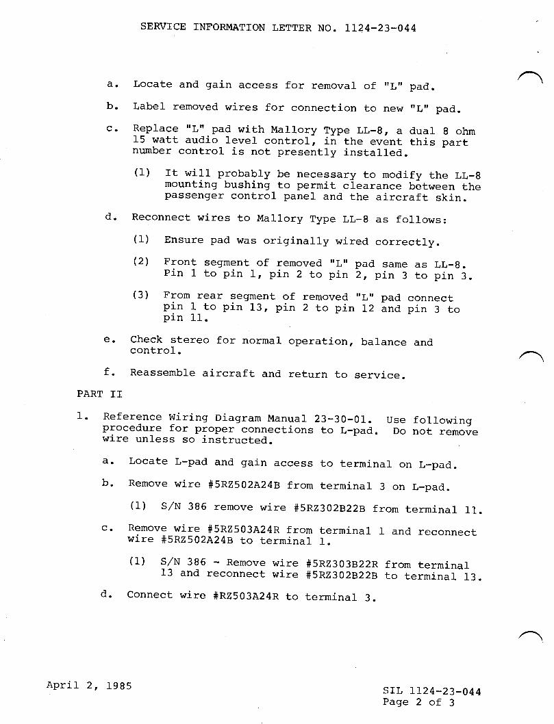
SERVTCE INFORMATTON LETTER NO. TL24-23-044
a. Locate and gain access for removal of 'Ln pad.
b- Label removed wires for connection to new "L' pad.
co Replace rrl,rr pad with Mallory Type LL-8, a dual g ohm15 watt audio Ievel control, in the event this partnumber control is not presently installed.(1) rt will probably be neeessary to modify the LL-g
mounting bushing to permit clearance between thepassenger control panel and the aircraft skin.d. Reconnect wires to Mallory Type LL-g as follows:
(1) Ensure pad was originally wired correctly.(2) Front segment of removed 'Lrr pad same as LL-g.Pin I to pin 1, pin 2 to pin 2, pin 3 to pin 3.(3) From rear segment of removed '|rl' pad connectpln 1 to pin 13, pin 2 to pin 12 lnd pin 3 topin 11.
e- check stereo for normal operation, balance andcontrol.f- Reassemble aircraft and return to service.
PART II
1. Reference wiring Diagram Manuar 23-30-01. use followingprocedure for proper connections to L-pad. Do not removewire unless so instructed.a. Locate L-pad and gain access to terminal on L-pad.b. Remove wire #5RZ5O2A24B from terminal 3 on L_pad.
(1) s/N 396 remove wire #5Rz3O2B22B from terminal 11.
c- Remove wire #5R2503A24R from terminal 1 and reconnectwire #5nZS02A24B to terminal 1.(1) S/N 386 - Remove wire #5R2303B22R from terminal13 and reconnect wire #5RZ3O2B22B to terminal 13.
d. Connect wire #R2503A24R to terminal 3.
srr, tI24-23-044Page 2 of 3
April 2, 1985
SERVICE INFORMATTON LETTER NO. 1124.23-044
(1) S/N 386 - Connect wire #5R2303822R Lo terminal11.
€. Check stereo for proper operation, balance andcontrol.
f. Reassemble aircraft and return to service.
srl, LI24-23-O44Page 3 of 3
April 2, 1985
TWTSERY'CEINFORMATION LETTER
srl, No. II24-23-O47
SUBJECT: COLLTNS HF220 SYSTEM IMPROVEMENTS
April 8, 1985
EFFECTMTY: MODEL L124/LL24A WESTWINDS, all serial numberswith HF.220 or provisions installed.
A. REASON
1. To prevent improper frequency selector operation dueto noise from other systems or when HF transmitter isin use. This problem appears as a change in selectedfrequency, orr you are unable to select a desiredfrequency.
2. To enable frequency readout digits to dim, and/orprevent HF.220 frgm causing NAV,/COM digit dimmingproblems.
B. REFERENCES
LL24/LL24A Wiring Diagram Manual, Chapter 23-10-0I.
C. PUBLICATIONS AFFECTED
IL24/LL24A Wiring Diagram Manual, Chapter 23-10-01.
D. DESCRIPTTON
1. Ensure CTL220 Collins Service Bulletin 1 and 2installed.
/ srl, lL24-34-047Page I of 2@ lill sms tp*n : !,!!*., *' n
SUBSIDIARY OF ISRAEL AIRCRAFT INDUSTRIES, LTD.
BEN GURION AIRPORT, ISRAEL
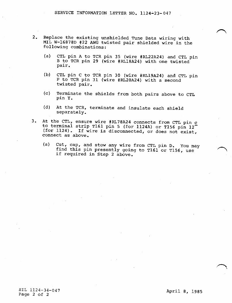
SERVICE INFORMATION LETTER NO. LT24-23-047
2. Replace the existing unshielded Tune Data wiring withMrL w-16878D #22 Awc twisted pair shierded wire in thefollowing combinations :
(a) crl, pin A to TCR pin 35 (wire #RL22A24) and crl, pinB to TCR pin 29 (wire #RLI8A24) with one twistedpair.
(b) crl, pin c to TCR pin 30 (wire #RL19A24) and crl, pinP to TCR pin 31 (wire #Rt20A24) with a secondtwisted pair.
(c) Terminate the shields from both pairs above to crl,pin y.
(d) At the TcR, terminate and insurate each shieldseparately.
3. At the crl., ensure wire #RL78A24 connects from crl, pin cto terminal strip T161 pin 5 (for 1124A) or T156 piir 12-(for rL24). rf wire is disconnected, or does not exist,connect as above.
(a) Cut, cdp, and stow any wire from CTL pin D. you mayf ind this pin present-ly going to TlGr or T156 r us€if required in Step 2 above.-
srr, II24-34-047Page 2 of 2
April 8, 1985
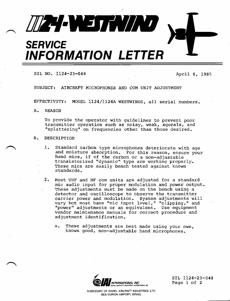
TilT{SERY'CEINFORMATION LETTER
srl, No. IL24-23-048
SUBJECT: AIRCRAFT MICROPHONES AND COM
Aprit 8, 1985
UNIT ADJUSTIVIENT
EFFEcrrvrrY: MODEL LL24/LL24A wEsrwrNDS, all serial numbers.
A. REASON
To provide the operator with guidelines to prevent poortransmitter operation such as noisy, weak, squeals, andI'splattering" on frequencies other than those desired.
B. DESCRIPTTON
Standard carbon type microphones deteriorate with ageand moisture absorption. For this reason, ensure yourhand mics, if of the carbon or a non-adjustabletransistorized I'dynamic" type are working properly.These mics are easily bench tested against knownstandards.
Most VHF and HF com units are adjusted for a standardmic audio input for proper modulation and power output.These adjustments must be made on the bench using adetector and oscilloscope to observe the transmittercarrier power and modulation. System adjustments willvary but most have rrmic input 1evelr'f ttclippingr" andI'poweril adjustments or an equivalent. Use equipmentvendor maintenance manuals for correct procedure andadjustment identification.a. These adjustments are best made using your own,
known good, non-adjustable hand microphones.
I.
2.
/
@lfllsmsw*l!*,*,nSUBSIDIARY OF ISRAEL AIRCRAFT INDUSTRIES, LTD.
BEN GURION AIRPORT, ISRAEL
srr, IL24-23-048Page 1 of 2
3.
SERVICE TNFORMATION LETTER NO. LL24-23-048
b. Always recheck the adjustments at a reduced DC inputlevel (22 volts) after adjustment at the normar 2i.svolts. Reset ttclippingtt and ttpower,t adjustments asneeded to prevent distortion and,/or carrier powerrrdrop outs. tt
NOTE
It is always wise to sacrifice sometransmitter power in favor of the propermodulation enveloper in the 1ong run youwill talk further, clearer; and reducethe possibility of transmitter failure.You will always be able to maintainminimum rated transmitter power if theunit is operating properly. This isespecially true for HF single-sidebandoperation.
Once the transmit,ters have been properly set for the"standardil input, adjust each dynamic type microphone(hand held or boom type) to equal the output of the'rstandardf' microphone as observed on the oscilloscope.Be sure the boom microphones are in your normar positionfor pickup.
El. AIso check the oxygen mask microphones in thesetests.
Now_ that you have a 'rmatched" systemr you can ad just anyreplacement microphones (refer to vendor instruclions) 6vusing transmit headphone sidetone and setting your newmicrophone output level for the same sidetone volume.Keeping the headphone volume control set low will permityou to hear sma1l changes in volume.
4.
srr. 1124-23-048Page 2 of 2
April 8, 1985
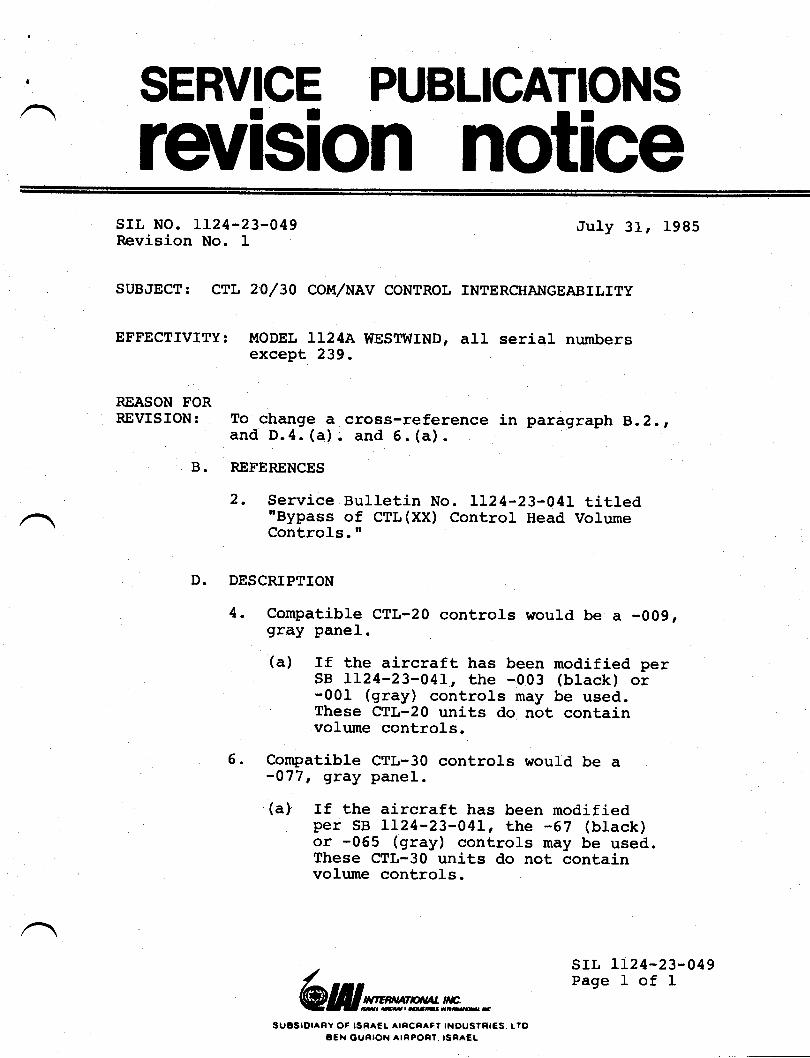
.-
,^. SERVICE
rcvision noticesrr. No. LL24-23-049Revision No. I July 31r 1985
SUBJECT: CTL 20/30 COIIT,/NAV CONTROL INTERCHAI{GEABILITY
EFFECTIVITY: MODEL LL24A WESTWIND, aII serj.al numbersexcept 239.
REASON TORREVISION: To change a cross-reference in paragraph 8.2.,
and D.4. (a) . and 5 . (a)
B. REFERENCES
2. Service Bulletin No. LL24-23-04I titled"Bypass of CTL(XX) Control Head VolumeControls.I'
D. DESCRIPTION
4. Compatible CTL-20 controls would be a -009,gray panel.
(a) If the aircraft has been modified perSB LL24-23-041, the -003 (black) or'001- (gray) controls may be used.' These CfL-20 units do not contain
voLume controls.
6. Compatible CTL-30 controls would be a-077r gEay panel.
(a) If the aircraft has been modifiedper SB LL24-23-041, the -67 (black)or -065 (gray) controls may be used.These CTL-30 units do not containvolume controLs.
/@Wwmmn*
suosrDlaRY oF lsFtA€L arFcRAFt rNoUStnrEs. LlogeN ounroN ArRPonl. rsRaEt
srl, 1124-23-049Page I of I
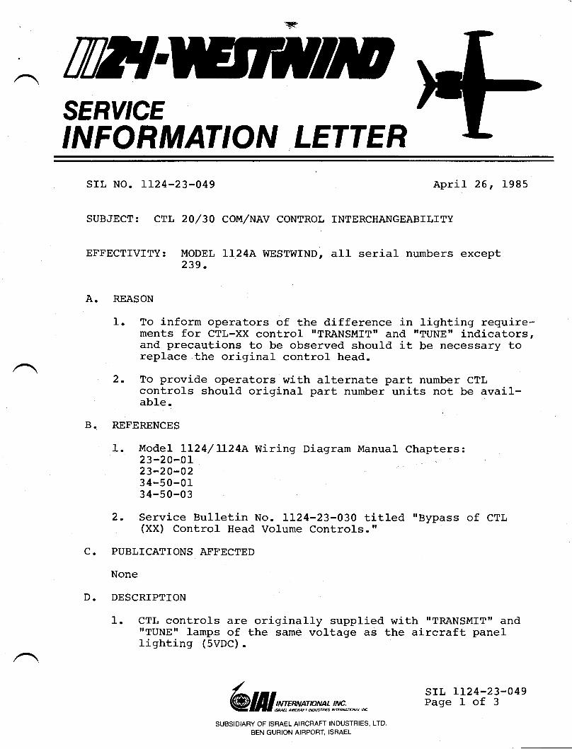
nflSERY'CE
'NFORMAT'ON LETTER
srl. No. 1124-23-049
SUBJECT:
EFFECTTVITY:
April 26, 1985
20/30 COMINAV CONTROL INTERCHANGEABILTTY
I{ODEL LL24A WESTWIND, all serial numbers except239.
A. REASON
1. To inform operators of the difference in lighting require-ments for CTL-XX control "TRANSMITT and "TUNEI indicators,and precautions to be observed should it be necessary toreplace the original control head.
2. To provide operators with alternate part number CTLcontrols should original part number units not be avail-ab1e.
REFERENCES
1. It{odel LL24/ IL24A Wiring Diagram Manual Chapters:23-20-OL23-20-023 4-50-0134-50-03
2. Service Bulletin No. LL24-23-030 titled "Bypass of CTL(XX) Control Head Volume Controls.rl
PUBLICATIONS AFFECTED
None
DESCRIPTION
1. CTL controls are originally supplied with "TRANSMfT" andrrTUNE" lamps of the same voltage as the aircraft panellighting (5VDC).
B.
c.
D.
/@ lI I wn**':*n*',!#;., *.,, *
SUBSIDIARY OF ISRAEL AIRCRAFT INDUSTRIES, LTD.
BEN GURION AIRPORT, ISRAEL
srr, 1124-23-049Page I of 3
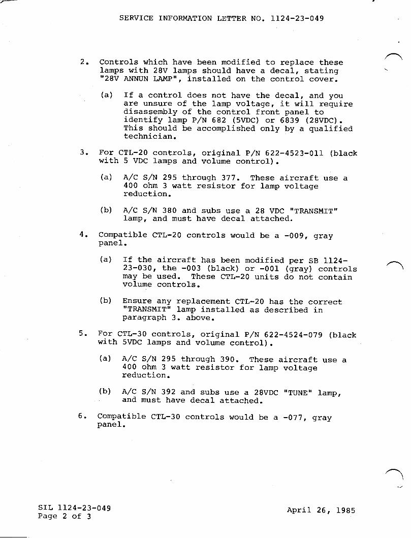
2.
SERVICE INFORMATION LETTER NO. IT24-23-049
Controls which have been modified to replace theselamps with 28V lamps should have a decal, stating"28V ANNUN LAI\,IP||, installed on the control cover.
(a) If a control does not have the decal, and youare unsure of the lamp voltage, it wilf requiredisassembly of the control front panel toidentify lamp P/N 682 (SVDC) or 6839 (2BvDc).This should be accomplished only by a qualifiedtechnician.
For CTL-20 controls, original p/N 622-4523-011 (b1ackwith 5 VDC lamps and volume control).(a) A/C S/N 295 through 3'17. These aircraft use a
400 ohm 3 watt resistor for lamp volLagereduction.
(b) A/C S/N 380 and subs use a 28 VDC "TRANSMIT"lamp, and must have decal attached.
Compatible CTL-20 controls would be a -009 r graypane1.
(a) rf the aircraft has been modified per SB LI24-23-030, the -003 (black) or -001 (gray) controlsmay be used. These CTL-20 units do not containvolume controls.
(b) Ensure any replacement CTL-20 has the correctI'TRANSMIT" Iamp installed as described inparagraph 3. above.
For CTL-30 controls, original prlN 622-4524-079 (bIackwith 5VDC lamps and volume control).(a) A/C S/N 295 through 390. These aircraft use a
400 ohm 3 watt resistor for lamp voltagereduction.
(b) A/C S/N 392 and subs use a 2BVDC ',TUNE" lamp,and must have decal attached.
6. Compatible CTL-30 controls would be a -077r graypanel.
3.
4.
5.
1
srr. 1124-23-049Page 2 of 3
April 26, 1985
SERVICE INFORMATTON LETTER NO. II24-23-049
(a) rf the aircraft has been modified per sB Lr24-23-030, the -067 (bIack) or -065 (gray) controls maybe used. These crl,-30 units do not contain volumecontrols.
(b) Ensure any replacement crl-30 has the correct "TUNE'Ilamp installed as described in paragraph 5. above.
7. Extreme caution must be used when replacing a crl-zT/lobecause of the lamp change.
(a) use of a 2BvDc lamp wilr result in a dim orinoperative lamp when instalred in place of a5VDC lamp CTL.
(b) use of a 5vDc lamp wilr result in lamp failure anddamage to the CTL when installed in place of a28VDC lamp CTL.
srr, IL24-23-049Page 3 of 3
April 26, 1995
23- 50-0 r23-s0-02
23-s0-0323-50-04
c.
D.
LL24/LL24A Maintenance l"lanua1, Chaptet 23-50-00 SIt LL24-23-048
PUBLICATIONS AFFECTED
LL24/LL24A t'taintenance Manual, Chapter 23-50-00 tdill be revisedto include this side-tone adjustment procedure.
DESCRIPTION
I. Cornply with Service Information Letter No. LL24-23-048.
2. External Po$ter, aircraft battery and master switches andAvionics Master switches (if so equipped) ON.
3. Tune and verify a VOR, LOC or ADF receiver identifier.Once observed, return all pitot and copilot audiospeaker,/phone switches to OFF.
/@ lII w:wm* !,!x^';n *.,,* srl, Lr24-23-060
Page I of 3SUBSIDIARY OF ISRAEL AIRCRAFT INDUSTRIES, LTD.
BEN GURION AIRPORT, ISRAEL
Til?ISERY'CEINFORMATION LETTER
srl, NO. 1124-23-050 January I0r 1986
SUBJECT: COI'iIIUNICATIONS - AUDIO - SIDETONE ADJUSTMENT PROCEDURES
EFFECTIVITY: II{ODEL LL24/LI24A WESTWINDS, AII SCTiAI NUMbCTS
A. REASON
To provide advanced maintenance manual revision information onhow to identify audio configurations and establish a means forproper adjustment of audio inputs,/outputs of aircraf t audiosystem.
B. REFERENCES
LL24/LL24A Wiring Diagram llanual' Chapters:
SERVICE INFORI{ATION LETTER II24-23-060
4. Select VHF COM I, vHF COIvl 2 and HF (if so equipped) onpilotrs llIC selector switch. DePress pilot's PTT, observesidetone in pilot speaker (not affected by SPKR VOLcontrol) and pilot's headsets (volume controlled by PHONEVOL control).
5. Note if sidetone also appears in copilot speaker. Selectcopilot audio switch for identifier observed above toSPKR. If identifier is muted during transmit' but isaudible when PTT is released, set cockpit speaker sidetoneadjustment located on 3468-3 control center to desiredlevel. Attempt to simulate a cockpit noise level similarto in-fliqht conditions is possible.
NOTE
Each transmitter must have the internalsidetone levels matched. This is normallya bench adjustment, the sidetone levelsshould be in the area of 50 milliwatts.Observe vendor procedures andspec i f icat ions .
6. Should no sidetone be present in pilot or copilot speaker,and the identifier selected is not muted during transmit,select the audio control switch for the transmitter in usefor test to SPKR position. If transmitter sidetone is nowobserved, and is controlled by the copilot SPKR VOLcontrol, it will be necessary to adjust the sidetone levelin each individual transmitter. The cockpit speakersidetone adjustment on the 3468-3 will have no effect.
NOTE
Each transmitter must have the internalsidetone adjustment IeveIs matched. This' is normally a bench adjustment, thesidetone levels should be in the area of Imilliwatts. For the VHF 20A/8, this isabout two fulI turns above zeto sidetoneoutput.
(a) It is necessary to compromise sidetone levels for thisconfiguration. Each transmitter sidetone output mustbe set high enough to be audible in the on-sideheadphones with the eHONES VOL set at normal in-flightposition, yet low enough to prevent cross-cockpitfeedback when the off-side audio selector switch is inSPKR position and the off-side SPKR VOL control is setat normal in-flight position.
srL LL24-23-060Page 2 of 3
January I0 r 1986
SERVICE INFORMATION LETTER NO. II24-23-O5O
7. Should no sidetone be present in copilot speaker butappears in pilot speaker, the identifier selected is notmuted and selection of the transmitter in use for test(copilot side, SPKR ON) does not result in copilot speakersidetone, then the on-side speaker sidetone may be set onthe 3468-3 control center to desired level. Observe NOTEabove (Aircraft serial numbers 349, 375 and subsequent) .
8. Repeat above procedures, set copilotts sidetone levels at3458-3 as required in Steps 5 and 7 above.
E. PA SELECTION ADJUSTII{ENT
1. Select pA on Pilot MIC SEL switch. Speak into MIC' adjustCabin PA level of 3458-3 control center as desired.
(a) Operate cabin stereo (if so equipped) and verify thatPA removes one stereo channel (normally the rightside) and that PA signal appears on this channel.
2. Repeat for copilot PA and 3468-3.
CAUTION
Some aircraf t equipped with Seat Belt,/NoSmoking chines may find that the ChimeGenerator unit connection will reduce PAvolume from the copilot side. It wiII benecessary to readjust PA and Chime toreach the desired level.
srr, rI24-23-060Page 3 of 3
January l0 r 1986
SERVICE PUBLICATIONS
retrision notice
,^
n
srl, No. LL24-24-005Revision No.l
,June 20, 1985
suBilEcr: rNSPEcrroN Al[D TEST oF PRroRrry BUs DroDEs
REASON FOBREvrsroN: To postfix an addendrm to the text forlowing
paragraph (13).
Addendur to text:Those aircraft modified in accordance withSeryice Bulletin No. LL24-24-00g must changeStep 7. (a) to read 0.7 to 1.5 volts toproperly refLect the fornard voltage dropreadings of the new 1N2784 priority gus diodes.
sB LL24-24-005Page I of 1
lrIENv,jTTN/4Lfr€.',,,,,t,re,&anattwS
IIUESIOIAFY OF ISRA€L ATRCRATI INDUSIRIES. LTOB€I{ OURION AIRPOFT. ISRAEL
: n?lSERY'CEINFORMATION LETTER
srr, No. LL24-24-005
SUBJECT: INSPECTION AND
December 3, L9g4
TEST OF PRIORITY BUSS DIODES
EFFECTIVITY: MODEL II24 ' LL24A WESTWIND, s/N L52, I54, I74, 185and Subs.
A. REASON
Introduction of a cockpit operaLional test to establish thecondition of the Priority Buss diodes located in the OverheadCircuit Breaker panel, RHS.
B. REFERENCES
II24/LI24A Maintenance Manual, Chapter 24-OO-OO.
C. DESCRIPTION
(1) External power connected and oN, Battery Master andboth Battery switches oN; both inverters in ALT, bothAvionics Master Switches OFF.
(2) Ensure the Distribution Buss Tie Breaker is in normalOPEN (pulled) condition.
(3) PuIl the three #2 (RHS) distribution Buss circuitbreakers.
(a) Fuel status system ON and operational.(b) RH generator OFF annunciator lamp OUT.
(4) Reset RHs distribution Buss breakers, pull the three #I(LHS) distribution Buss breakers.
(a) Fuel_ status system ON and operational.(b) LH generator OFF annunciator lamp OUT.
/ srL 1I2 4-24-005Page 1 of 2
SUBSIDIARY OF ISRAEL AIRCRAFT INDUSTRIES, LTD.
BEN GURION AIRPORT, ISRAEL
@ lII st'ms|ptvt* t#;,^-,*
December 3, 1984
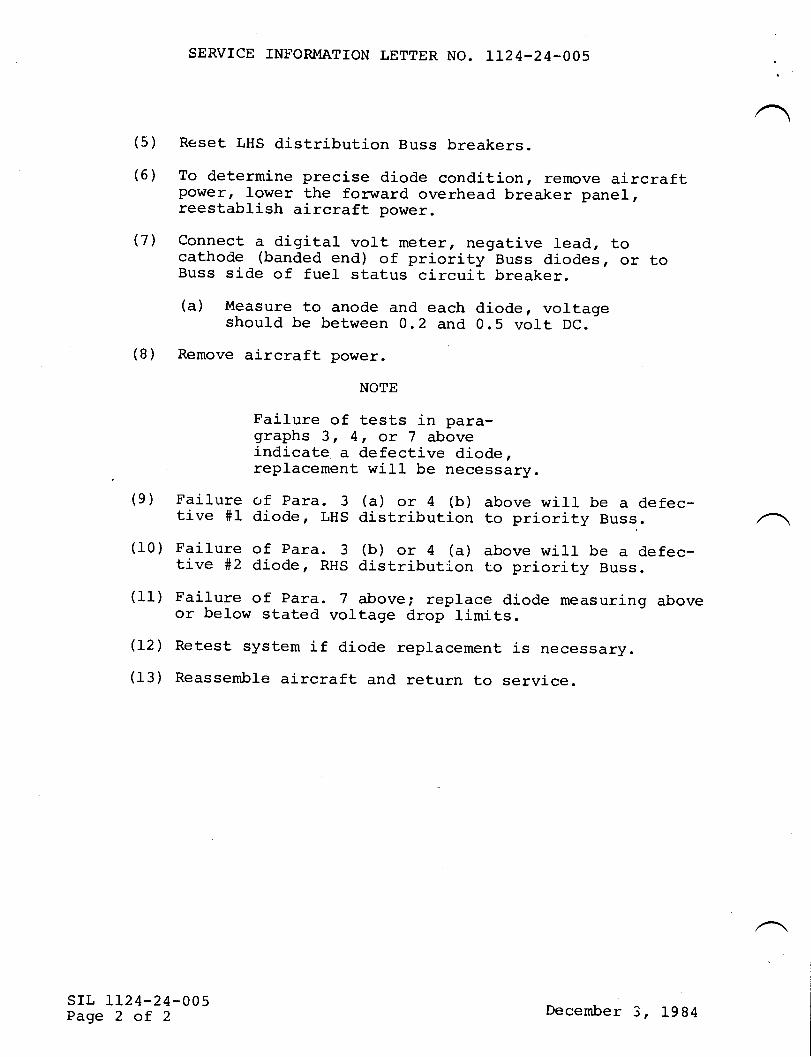
SERVICE IN}'ORMATION LETTER NO. IL24.24-OO5
(5) Reset LHS distribution Buss breakers.(6) To determine precise diode condition, remove aircraft
power, lower the forward overhead breaker panel,reestablish aircraft power.
(7'l Connect a digital volt meter, negative lead, tocathode (banded end) of priority Buss diodes, or toBuss side of fuel status circuit breaker.
(a) Measure to anode and each diode, voltageshould be between 0.2 and 0.5 volt DC.
(8) Remove aircraft power.
NOTE
Faj-lure of tests in para-graphs 3, 4, or Z aboveindicate a defective diode,replacement will be necessary.
(9) Failure of para. 3 (a) or 4 (b) above will be a defec-tive #1 diode, LHS distribution to priority Buss..
(10) Failure of para. 3 (b) or 4 (u) above will be a defec-tive t*2 diode, RHS distribution to priority Buss.
(11) Failure of para. 7 above; replace diode measuring aboveor below stated voltage drop limits(72) Retest system if diode replacement is necessary.
(13) Reassemble aircraft and return to service.
srl, 1124-24-005Page 2 of 2 December 3, 1984
TilT{SERY'CEINFORMATION LETTER
SIL NO. 1124-24-006 December ll, l9g4
SUBJECT: ALTERNATE PART FOR ENGINE PYLON FIREWALL BULKHEADCONNECTORS J313 and J314.
EFFEcrrvrrY: MODEL )L24, serial number L52, I54, L74, 18I, 185through 300.
A. REASON
To announce the availability of an alternate bulkheadconnector P/N MS3450KT28-2I5.
B. DESCRIPTION
rntermittent operations have been reported from the fierdinvolving powerprant systems. Troubleshooting of thesesystems revealed a defective J313 and J314 bulkhead connector.Investigations traced the problem to a cracked ceramic insertin each of the connectors.
Cracked connector inserts may not be visible, as the failurenormally occurs at the point the insert attaches to theconnector shell. This causes the connector pin latches toloosen, whj-ch in turn allows the pin to float, eventualrywearing the connector pin.
rt is this wearr or loss of tension, that causes the problem,as the plating is eventually removed. Cleaning the connectorwith contact cleaner only derays replacement; in additionsome contact cleaners will contaminate the plug insert. Thiscauses additional problems.
To determine if the plug insert is broken; use a thin jawneedle nose pliers, insert into any two pin holes diametrically
'opposed near plug shell.
@ II I *t'ms,p*t* ;#;., ̂ ̂ , *srL 112 4-24-006
Page I of 2
/
SUBSIDIARY OF ISRAEL AIRCRAFT INDUSTRIES, LTD
BEN GURION AIRPORT, ISRAEL
SERVICE INFORMATION LETTER NO. LL24-24-006
The replacement part, MS3450KT28-21s, does not incorporatea ceramic insert and is not susceptible to cracking.
Apply a twisting motionr at theinsert. If the plug insert isfrom the she1l
If separation occurs, you mustwill be unable in most cases topIace.
If operators experience similarsystems, it is recommended thatinvestigate connectors J313 and
same time pulling on thecracked, it will separate
replace the connector, as youpush the insert back in
problems with powerplantmaintenance personnelJ314.
srr, 1124-24-006Page 2 of 2
December 11, 1984
SERY'CEINFORMATION LETTERsrL No. LL24-24-0198 November L4, 1986
(This Service Information Letter dated November L4, 1985 supersedesService Information tetter No. IL24-24-019A dated I'tay 9, f986, ServiceInformation Letter No. LL24-24-019 dated February 20, 1985r RevisionNo. I dated June 20t f985 and Revision No. 2 dated November 15, I9g5 intheir entirety. )
SUBJECT: DISTRIBUTION BUS CIRCUIT BREAKER INSPECTION
EFFECTIVITY: II{ODEL LT24/LL24A WESTWINDS, aII serial numbers
A.
C.
B.
REASON
To provide a positive meansOverhead Panel distribution
REFERENCES
of inspecting the Aft Contactor Box andbus circuit breakers.
D.
LL24 wiring Diagram Manual, Chapter 24
PUBTICATIONS AFFECTED
IL24 lr{aintenance Manual, Chapter 24
INSTRUCTIONS
PART A . (TOOLING)
(f) Construct a load bank using 3 ea.0.14 Ohmr lKw resistors(Ohmite P,/N 2303A) connected in ser ies. Ref erence Figure Iduring construction and for wire connection/indentification.(a) Prepare two jumper wires from #8 AWG wire (MIL-W-22729) ,
length not to exceed six inches.
/@ lI I smw mn * !,!x?;., *, *
SUBSIDIARY OF ISRAEL AIRCRAFT INDUSTRIES, LTD
BEN GURION AIRPORT, ISRAEL
SIL LL24-24-0198Page I of 5
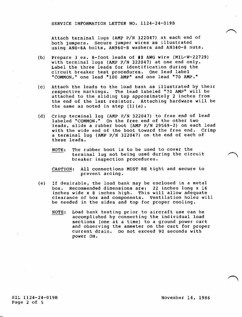
SERVICE INFORI{ATION LETTER NO. LL24-24-OI9B
Attach terminal lugs (AMP P/N 322047) at each end ofboth jumpers. Secure jumper wires as illustratedusing AN8-6A bolts, AN960-8 washers and AN340-8 nuts.
(b) Prepare 3 ea. 8-foot leads of #8 AWG wire (MIL-W-227291with terminal lugs (A!,tP P/N 322047) at one end only.tabel the three leads for identification during thecircuit breaker test procedures. One lead labeInCOMII{ON, " one lead " I00 Al{Pn and one lead n 70 AljlP. rr
(c) Attach the leads to the load bank as illustrated by theirrespective markings. The lead labeled "70 AMP" wiII beattached to the sliding tap approximately 2 inches fromthe end of the last resistor. Attaching hardware will bethe same as noted in step (1) (a).
(d) Crimp terminal lug (Al,lP P/N 322047', to free end of leadlabeled "COM!,!ON.n On the free end of the other twoIeads, slide a rubber boot (Al.{P P/N 29569'2) on each leadwith the wide end of the boot toward the free end. Crimpa terminal lug (Al{P P/N 3220471 on the end of each ofthese leads.
NOTE: The rubber boot is to be used to cover theterminal lug not being used during the circuitbreaker inspection procedures.
CAUTION: AII connections I',[UST BE tight and secure toprevent arcing.
(e) If desirable, the load bank mgy be enclosed in a metalbox. Recommended dimensions are: 22 inches long x t6inches wide x 8 inches high. This will allow adequateclearance of box and components. Ventilation holes wiIIbe needed in the sides and top for proper cooling.
NOTE: Load bank testing prior to aircraft use can beaccomplished by connecting the individual loadsections (one at a time) to a ground power cartand observing the ammeter on the cart for propercurrent drain. Do not exceed 90 seconds withpower ON.
srr, LI24-24-019BPage 2 of 5
November L4, 1986
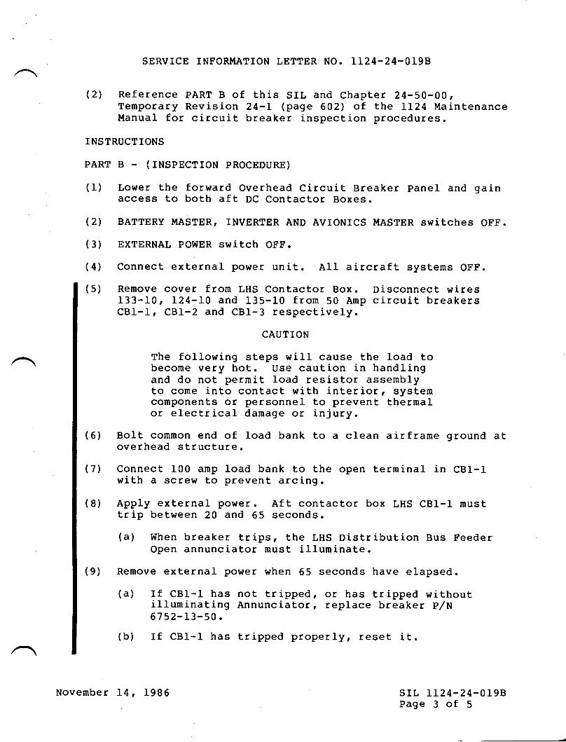
SERVICE INFORI,IATION LETTER NO. 1I24-24-OI98
(2) Reference PART B of this SIL and Chapter 24-50-00,Temporary Revision 24-L (page 602) of the LL24 tilaintenanceIt{anual for circuit breaker inspection procedures.
INSTRUCTIONS
PART B - (INSPECTION PROCEDURE)
(1) Lo$ter the forward Overhead Circuit Breaker panel and gainaccess to both aft DC Contactor Boxes.
(2) BATTERY I,IASTER, INVERTER AND AVIONICS II{ASTER switches OFF.
(3) EXTERNAL POWER switcb OFF.
(4) Connect external pohrer unit. All aircraft systems OFF.
(5) Remove cover from LHS Contactor Box. Disconnect wires133-10, L24-L0 and 135-10 from 50 Amp circuit breakersCBt-1, CBI-2 and CBl-3 respectively.
CAUTION
The following steps will cause the load tobecome very hot. Use caution in handlingand do not permit load resistor assemblyto come into contact with interior, systemcomponents or personnel to prevent thermalor electrical damage or injury.
(6) Bolt common end of load bank to a clean airframe ground atoverhead structure.
(7') Connect 100 amp load bank to the open terminal in CBI-Iwith a screw to prevent arcing.
(8) Apply external povrer. Aft contactor box LHS CBI-I nusttrip between 20 and 65 seconds.
(a) When breaker trips, the LHS Distribution Bus FeederOpen annunciator must illuminate.
(9) Remove external power when 65 seconds have elapsed.
(a) If CBI-I has not tripped, or has tripped withoutilluminating Annunciator, replace breaker p/N6752-L3-50.
(b) If CBI-I has tripped properly, reset it.
November L4, 1986 srL LL24-24-0198Page 3 of 5
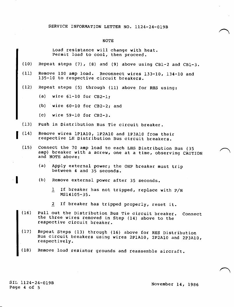
SERVICE INFORMATION LETTER NO, LL24.24-OI9B
NOTE
Load resistance rrill change rrrith heat.Permit load to cool, then proceed.
(r0) Repeat steps (7), (8) and (9) above using cB1-2 and cBr-3.(11) Remove 100 amp load. Reconnect wires 133-10, 134-ro and
I35-f0 to respective circuit breakers.
(12) Repeat steps (5) through (11) above for RHS using:(a) wire 6I-10 for CB2-Li
(b) wire 60-10 for CB2-2i and
(c) wire 59-10 for CB2-3.
(13) Push in Distribution Bus Tie circuit breaker.(14) Remove wires 1plA10, 1p2At0 and rp3Aro from their
respective LH Distribution Bus circuit breakers.(15) connect the 7o amp load to each LHs Distribution Bus (35
amp) breaker with a scre!", one at a time, observing CAUTIONand NOTE above:
(a) Apply external power; the OHp breaker must tripbetween 4 and 35 seconds.
(b) Remove external poyrer af ter 35 seconds.
f If breaker has not tripped, replace with p/HIrlSI4t05-35.
2 If breaker has tripped properly, reset it.(f6) Pull out the Distribution Bus Tie circuit breaker. connectthe three wires removed in Step (I4) above to therespective circuit breaker.
(17) Repeat Steps (f3) through (16) above for RHS DistributionBus circuit breakers using wires 2p1AI0 | 2PZALO and 2p3AI0,respectively.
(18) Remove load resistor grounds and reassemble aircraft.
I
I
SIL LL24-24.0L98Page 4 of 5
November 14 t l9B6
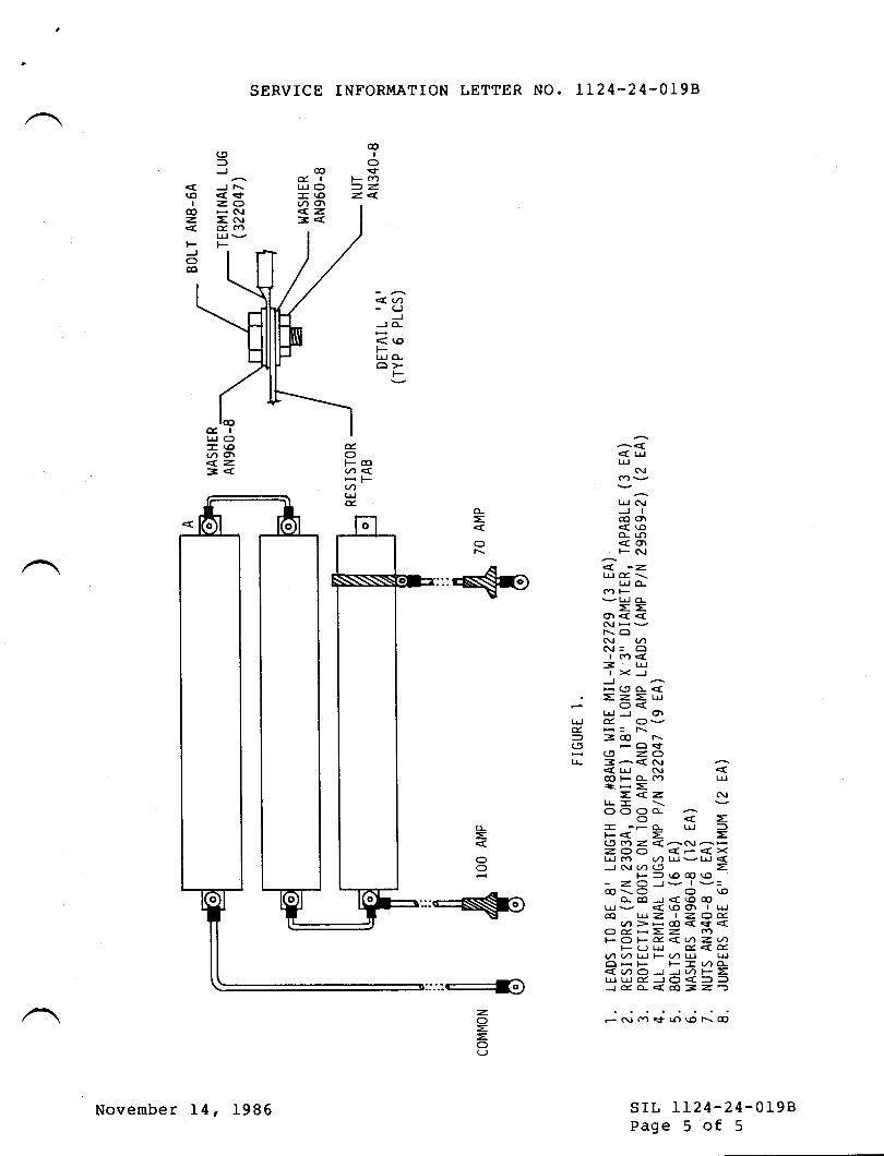
SERVICE INFORMATION LETTER NO. LLz4-24.0T98
@I
O.<tFoo=2.z. <.
@d. ll4J O-(o(/, ot<.2=<
(5
-JJT\<<r=QH (\,1
=Grd c')LllvF
(oI
@zFJoco
<, t)-(J
JJO-
< '.oF-tal O-6>-
F
< lattrJ (\I(nv
trJ (\tJICO Or<\oo- rr)<olF(\I
lrl d'\r! o_(frF
vul o_
==or<<(\l
-vr.- ONA(t= oI Cf)<
=r!| ><J-JH(5O-<
. =Z=lrJo<[!J or
laf G,d, H= r\= =@
r'-(t -O<fc5 =ol! 3^< Cv
< LrJ (\tcc|Fo- (Y) Ld.ttsH=
Z, <.2. (\JLL- \r
OOOA-O
- reo- Ld =F< = =A (a Z. {a(!--Z.OQ {-{>(t! ..) U) trJ v t^.1 <JC!('L'
=F=(c)@(O- z.Q -Jv I v-@-\O O to
o-coJ<\o@LrJv <\oo\ | Luco srz. | =.Qd..vi)7-@<<f<9g!-Z.Z (YtFOFX.<.(.nZ.V)
F(Jtrl d.<.du)Lnu)FqauJ !JOHF F-lrO-<(/)oJJ(/)F=trJLrJdJO<==Jdo-<co=z')
=or\
d,.lrl O- r.o(/) or<. z.=<
z.
==
sr[, LL24-24-0198Page 5 of 5
November L4, 1986
THSERY'CEINFORMATION LETTER
srr, No. LI24-24-023 February 25, 1985
SUBJECT: MINIMTZTNG PRECIPITATION STATIC INTERFERENCE THROUGHFROPER AIRCRAFT BONDING.
EFFECTIVITY! MODEL LL241LL24A WESTWINDS, all serial numbers.
A. REASON
To ensure that all flight controls, fiberglass or compositematerials, antennasr dnd inspection panels are bonded toeliminate airframe generated P-Static.
B. REFERENCES
LL24/LL24A Maintenance ManualChapters z 23-60-00
24-0 0-0030-10-005 3-5 0- 00
sB ww-2495AsB IL24-23-016srl, 1124-23-AL6
C. PUBLTCATTONS AFFECTED
IL24/IL24A Maintenance Manual.Chapters: 23
243055
@lf,lsrwm*:!ti;,^.,,* srl, rr24-24- 023Page 1 of 6
/
SUBSIDIARY OF ISRAEL AIRCRAFT INDUSTRIES, LTD
BEN GURION AIRPOHT, ISRAEL
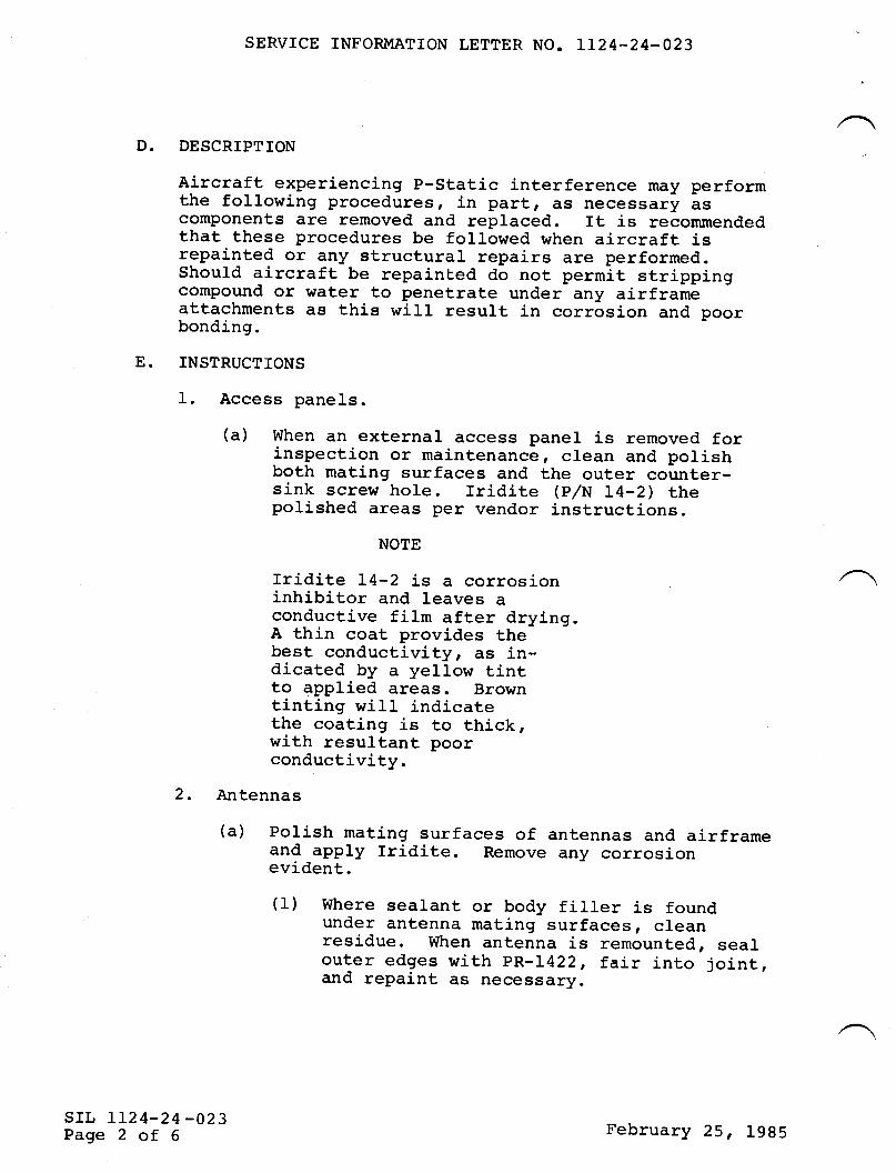
D.
SERVICE INFORMATION LETTER NO. LT24^24-023
DESCRIPTION
Aircraft experiencing p-static interference may performthe following procedures, in partr :tS necessary ascomponents are removed and replaced. rt is recommendedthat these procedures be followed when aircraft isrepainted or any structural repairs are performed.Should aircraft be repainE.ed do not permit strippingcompound or water to penetrate under any airframeattachments as this will resurt in corrosion and poorbonding.
INSTRUCTIONS
1. Access panels.
(a) When an external access panel is removed forinspection or maintenance, clean and polishboth mating surfaces and the outer count,er-sj-nk screw hole. fridite (p,/N I4-2) thepolished areas per vendor instructions.
NOTE
Iridite I4-2 is a corrosioninhibitor and leaves aconductive film after drying.A thin coat provides thebest conductivityr ES in-dicated by a yellow tintto applied areas. Browntinting wilI indicatethe coating is to thick,with resultant poorconductivity.
2. Antennas
(a) Polish mating surfaces of antennas and airframeand apply lridite. Remove any corrosionevident.
(1) Where sealant or body filler is foundunder antenna mating surfaces, cleanresidue. When antenna is remounted, sealouter edges with pR-L422, fair into joint,and repaint as necessary.
E.
srr, LL24-24 -023Page 2 of 6 February 25, 1985
SERVICE INFORMATION LETTER NO. IT24-24-023
(2) DO NOT PAINT any antennas, as this will createanother insulating area over antenna housingand reduce antenna efficiency as well as in-creasing probability of P-Static generation.
(3) Where possible, clean out counterboredantenna mounting screw holes until metalsurface is exposed, and install internaltooth star washer (MS35333) of proper sizeunder screw heads prior to installation. FiIlcounterbore with PR-L422 sealant afterassembly.
(b) Where antenna uses metallized gasket for airframebond, ensure gasket is not deformed or corrodedprior to reassembly. If in doubt, replace gasket.
(c) Upon reassembly, ensure proper seal to prevententry of any contaminants and cabin pressureleaks, where applicable.
3. Deicer boots. (Reference Maintenance Manual, Chapter30-10-00 )
(a) fnspect both trailing edges of all deicer bootsfor proper bonding to aj-rframe.
(1) There should be a layer of A-56-8 conductivecement overlapping the boot and surface colorcoat about L/2 inch each, with bare metalexposed between boot and paint approximatelyL/4 inch wide that will become the bond forthe conductive cement. Application of theboot over the color coat will result in nobond, even with the A-56-8 cement applied.
(2') Application of deicer boot to metal surfacesshould be over bare meta1, and conductivecement used.
(3) Gently scrape away a small area behind eachboot trailing edge, and ensure no color coator primer exists under conductive cement.
(b) Check boot conductivity and bonding with astandard ohmmeter. Ensure a good ground with the(-) lead, and trace along boot surface with flatedge of probe. Resistance value will vary,however no sudden high resistance or opens shouldbe noted. Do not touch meter leads.
srr, rI24-24-023Page 3 of 6
February 25, 1985
SERVICE INFORMATION LETTER NO. LL24-24-023
(1) Use of Stainless Steel probes recommended.
(2) Do not use probe tip on boot surface, or apuncture will occur.
(c) If boot surface is dull and appears s1i9ht1y brown,the boot is suspect. Application of "Age Master" toentire boot will partially restore boot conductivity.
(d) If conductive adhesive cap strip is crackedr or"crazedr" it is subject to removal and replacemenLdue to poor bonding.
4. Airframe. (Reference Maintenance Manual, Chapter24-00-00).
(a) Perform bonding tests to Aircraft Battery groundattach point. Repair broken or frayed bond strips.Polish attach points and apply Iridite I4-2 priorto reassembly of suspect areas.
(b) Satisfactory inspection of airframe P-Staticrejection may only be accomplished by a P-Staticskj-n map. Most major Service Centers have thiscapability, and the test will show Airframe andFiberglass components improperly bonded or treated.(1) Meta1 skin surfaces reflecting a high discharge
resistance are probably filled with bodyfi1Ier.(a) Remove filler if desired, reprime and
paint affected areas.
(b) Shou1d it be desired to retain body filler,remove primer and color coat fromaffected areas until surrounding baremetal is exposed. Apply a Type I, highconductivity, Anti-Static coating to over-Iap body filler and exposed metal, re-paint with color coat as required.
5. Fiberglass or Composite Material. (Reference MaintenanceManual Chapter 53-50-00) .
(a) These areas must be completely covered with Type I,high conductivity, Anti-static coatj-ng prior tocolor coat.
srr, LL24-24-023Page 4 of 6
February 25, 1985
SERVICE INFORMATION LETTER NO. T124-24-023
(1) Wing tank tail cones, wing to tip tankfairings, flap hinge fairings, MLG fairings,Dorsal fin, fnverter and Ram Air inlets.
These areas must be completely covered with Type 2,low conductivity, Anti-Static coating prior tocolor coat:
(1) Radome, Vertical Stabii-izer Tip.
AlI areas must be sanded down and a new layer ofAnti-Static coating applied pri-or to repaint.Should repaint occur without this step anadditional insulating layer has been formed and theprobability of P-Static generation will increase.
When applying Anti-Static coating, it is recommendedthat the coating overlap any sealant or body fillerand be allowed to bond to bare metaI. In addition,it is highly recommended that al1 composite areamounting screws be backed out enough to permitAnti-Static coating to adhere to area under screwheads. The screws may then be secured whencoating is dry.
A quick test to determine if Anti-Static coatingexists is to use your standard VOM, (-) lead toground, and penetrate color coat at suspect areas atseveral points using a 50 angle from the surface.You should experience a high resistance from anypoint penetrated. Resistance value will varyr noresistance will indicate no conductive coatingr oran excess of color coat.
Radome, tip tank tail cones, and Vertical Stabilizer tipcontain diverter strips. Reference SIL 112 4-23-016 totest and inspect diverter strips, and ensure propermounting and bonding.
(a) The radome anti-erosion cap should be of the mylarthermoform type, and it must bond directly to theAnti-Static coating. Under no circumstances shouldthis cap be instaLled directl-y over the color coat.
(b) It is advisable to apply another coating of Anti-Static paint over the myJ-ar cap prior to applyingcol-or coat to radome.
srL 112 4-24-023Page 5 of 6
(b)
(c)
(d)
(e)
6.
February 25, 1985
SERVICE INFORMATION LETTER NO. LL24-24-023
(c) shourd replacement of diverter strips be necessaryit i-s recommended they be installed over anti-staliccoating with conductive cement, and another layerof Anti-Static coating be applied over thediverter strip.
7. Flight Controls and Static Wicks, ReferencesB Lr24'23-016 and srl, rL24-23-ol6 for inspectionand test procedures.
(1) If diverter strip replacement is not desired,ensure Anti-Static coating is applied overdiverter strip.
8. Tail Cone.
Ensure bond strap is present, and quick disconnectsare connected. polish and rridite inner cone surfaceand airframe around fastener attachment areas.
srr, IL24-24-023Page 6 of 6
February 25, 1985
TilFTSERY'CEINFORMATION LETTER
A.
SIL NO. LL24-24-037 March 2L, 1985
SUBJECT: STORAGE OF NICKEL CADMIUM AIRCRAFT BATTERIES
EFFECTMTY: MODEL LL24/LL24A WESTWINDS, all serial numbers.
REASON
To remind aircraft operators to adhere to aircraft batterymanufacturerrs requirements prior to short or long termbattery storage.
REFERENCES
None
PUBLICATIONS
None
DESCRTPTION
The aircraft nickel cadmium batteries may be storedindefinitely, charged or discharged, provided specificinstructions are adhefed to and the storage atmosphere iscool, clean, dry and non-corrosive.
The battery manufacturerrs instruction manual outlinesprocedures for short and long term storaqe.
Reference should be made to the following publications forsLorage instructions:
q.
c.
D.
/
@ II I w:ms w* t !,!Y;, *,, nSUBSIDIARY OF ISRAEL AIRCRAFT INDUSTRIES, LTD,
BEN GURION AIRPORT, ISRAEL
srL LL24-24-037Page I of 2
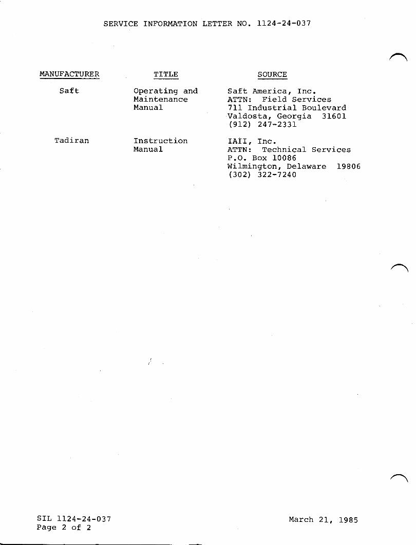
SERVICE INFORMATION LETTER NO. LI24.24-037
TITLE SOURCEMANUFACTURER
Saft
sTL 1124-24-037Page 2 of 2
Operating and Saft America, Inc.Maintenance ATTN: Field ServicesManual
Tadiran Instruction IAII, Tnc.Manual
7LL Industrial BoulevardValdosta, Georgia 31601(9r2) 247-233r
ATTN: Technical ServicesP.O. Box 10086Wilmington, Delaware 19806(302) 322-7240
March 2I, 1985
TilT{SERY'CEINFORMATION LETTER
srL No. LL24-24-054 June 5, 1985
SUBJECT: AC STATIC INVERTER TMPROVEMENTS
EFFECTIVITY: MODEL LL24/II24A WESTWIND, all serial numbers.
A. REASON
To prevent severe damage to Avionics and electrical equipmentpowered by the 1A1000-1D static inverter in the event ofinverter overvoltage protection system failure.
The result of the failure mode is an extremely high voltageappearing on both the 115 volt and 26 volt Hz AC electricalbus, which can cause system failures. These system failureswill probably occur for a system tg fail at an indeterminatelater date due to the overvoltage condition.
B. REFERENCES
LI24 Service Bulletin WVI-24-26.
C. PUBLICATIONS AFFECTED
None
D. DESCRIPTTON
1. Ensure your aircraft has been modified to comply with thereference Service Bulletin.
2. Contact the vendor prior to shipping your inverter, forcost and turnaround time, Atlantic Aviation Supply Co.has modified units available for exchange.
3. Units modified under this program will be identified bythe letter trMrr stamped after the unit serial number.
@lill srm*p***!#;,*,*srl, lL24-24-054Page I of 3
SUBSIDIARY OF ISRAEL AIRCRAFT INDUSTRIES, LTD
BEN GURION AIRPORT, ISRAEL
/
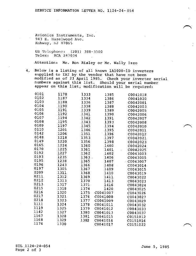
SERVTCE INFORMATION LETTER NO. TI24-24- 054
Avionics Instruments, fnc.943 E. I{azelwood Ave.Rahwcry , I'iJ 07 06 5
US Tcl,cphonc: (20f) 3BB-3500Telex: RCA 247034
Attention: Mr. Ron Risley or Mr. Wally Izzo
4. Below is a listing of all known 1A1000-1D inverterssupplied to IAI by the vendor that have not beenmodified as of 23 April 1985. check your inverter serialnumbers against this list. Should your serial numberappear on this list, modification will be required:
0101010201030104010s0106010 7010 I010901100I42014 8014 9015501700L92019 3019501960l-97020902 1102L202130 21502L602r702 181r1lIII9LI42Il67I16 B
LT7 4
srl, 1124-24-054Page 2 of 3
1t7 81187118 811901191Itg2119 4119 5LLg7L2OLL206I2L8L220I224r225L22712 35l-23812431305I 311L312131 31 3171318132 01 32I132 3r32413251327132 8L3291330
1333 13851334 13861336 13871338 13881339 13891341 1390L342 13911343 13931345 13941346 139s1351 13961353 13971355 13981360 14001361 t40lL362 L4021363 14061365 L4071366 1408L367 14091368 I4l01369 14111370 14131371 14161374 14201375 C0041007L376 c0041008L377 C0041009I378 c00410r11379 C0041012r380 c00410131381 C00410151382 c0041016
c0041017
c00 41018c00 41020c00 42 001c00 42 00 3c00 42 005c00 4 2006c004 2007c004 2 00 Ic00 4 2 010c00 42 011cQj420L2c004202Ic004 2023c0042024c0042025c004 3003c004 3005c004 300 7c00 4 3 014c004 3015c00 4 301 9c004 3022c004 3023c004 3024c004 3025c004 3026c004 3027c004 3029c004 3032c0043033c0043037cor510 12c015 1016c015 1022
June 5, 1985
SERVICE INFORMATION LETTER NO. II24-24-064
c015I026c0152 005c0152 006c0152 010c0I52026c0L52027c0L52029c0r52031c0L52032c0152 0 3 3c0152 034c01520 35c0L52044c0152 045c015 300 1c015300 4c015 3005c015 3006c015 300 7c0153 00 8c0I5 3010c0r53011c0 15 301 3c015 3016c015 3017c015301 Ic018100 1c0181002c0I8100 4c01 8100 5c0181010c01810r1c0181012c0181014c01 81015c0181017c018r019c01 I 102 rc018r022c018102 3c0r8102 4c0181026c01 81029c01810 30c01810 3 3c01 810 35c01810 36c0I810 38c01 8l 04 4
col82 00 3cor82 005c0182006c0182 00 Ic0L820L2c0182 017c01 82 018c0L82022c0L82026c0L82027c0182 030col82032c01820 34c0182 035c0I 82 0 38c0182039c0182040c0182041c0L82042c0182 044c0182045c01 82 0 46c01 8204 Ic01 82 050
srl, LL24-24-054Page 3 of 3
June 5, ]985
SERVICE INFORMATION LETTER NO. LL24-24-0.54
a
c015102 6c0152 005c0I52 006c0152 010c0152026c0I52027c0152029c0152 031c0I52032c0152033c0152 034c01520 35c0r52044c0152 045c015 3 001c015 3 00 4c015 3005c015 3006c015 300 7c0153008c015 3 01 0c015 3 011c0 15 3 013c015 3016c015 3 017c015 301 Ic0181001c0181002c018100 4c018100 5c0r81010c01 81011c01 81 012c0181014c0181015c0181017c0181019c0181021c0181022c018102 3c018102 4c0I81026c01 81029c01810 30cor810 3 3c01810 35c01810 36c0I810 38c01 81 04 4
c0182 00 3c01 82 005c0182 006c01 82 00 8c0L820L2c0182 01 7c01 82 018c0L82022c0L82026c0L82027c0r82 030col82032c01820 34c0182 035c01820 38c0I 82 03 9c0182040c0182 0 41c0L82042c0182 044c0182045c0182046c01820 4 8c01 82 050
srL LL24-24-054Page 3 of 3
June 5, 1985
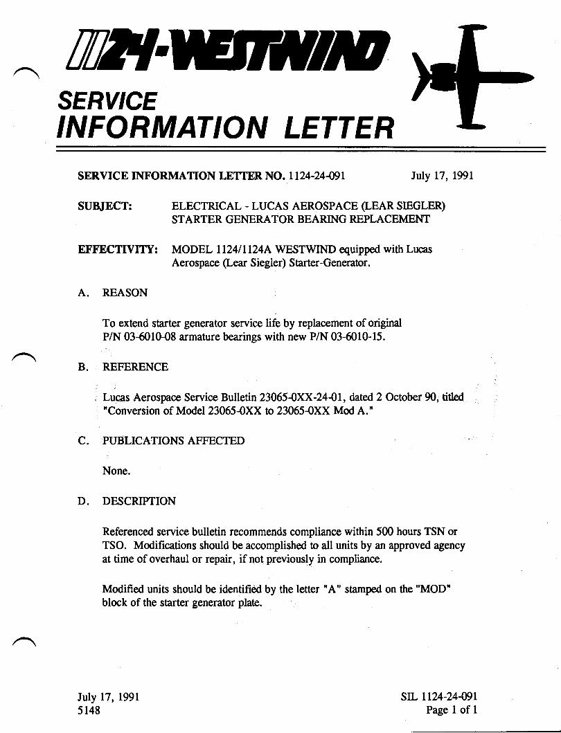
TWTSERY'CEINFORMATION LETTER
SERVICE INFORMATION IJTTER. NO. 1124-24-09I Iuly 17, 1991
SU&IECT: ELECTRICAL - LUCAS AEROSPACE (LEAR SIEGLER)STARTER GENERATOR BEARING REPLACEMENT
EFFECTIVITY: MODEL LL24ll124A WESTWIND equipped with LucasAerospace (Lear Siegler) Starter-Generator.
A. REASON
To extend starter generator service life by replacement of originalP/N 03-6010-08 armature bearings with new P/N 03-6010-15.
B. REFERENCE
Lucas Aerospace Service Bulletin 23065{XX-244I, dated 2 October 90, titled"Conversion of Model23065-0XX to 230654XX Mod A.'
C. PUBLICATIONSAFFECTED
None.
D. DESCRIPTION
Referenced service bulletin recommends compliance within 500 hours TSN orTSO. Modifications should be accomplished to all units by an approved agencyat time of overhaul or repair, if not previously in compliance.
Modified units should be identified by the letter "A" stamped on the UMODU
block of the starter generator plate.
Iuly 17, 1991
5148str. 1124-24-WL
Page 1 of 1
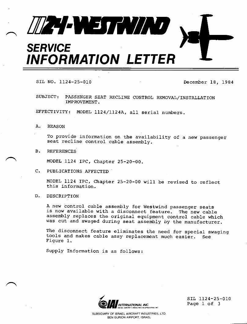
rw{SERY'CEINFORMATION LETTER
A.
B.
srl, No. 1124-25-010 December 18, 1984
SUBJECT: PASSENGER SEAT RECLINE CONTROL REMoVAL/INSTALLATIoNIMPROVEMENT.
EFFECTIVITY: MODEL IL24/LL24A, all serial numbers.
c.
REASON
To provide information on the availability of a new passengerseat recline control cable assembly
REFERENCES
MODEL II24 IPC, Chapter 25-20-00.
PUBLICATIONS AFFECTED
MODEL rL24 rPc, chapter 25-20-00 will be revised to reflectthis information.
DESCRIPTION
A new control cable assembly for westwind passenger seatsis now available with a disconnect feature. The new cableassembly replaces the original equipment control cable whichwas cut and swaged during seat assembly by the manufacturer.The disconnect feature eriminates the need for special swagingtools and makes cable assy replacement much easier. seeFigure 1.
Supply Information is as follows:
D.
/@ lfll st:n*sm* !J!r;.,*n,n
SUBSIDIARY OF ISRAEL AIRCRAFT INDUSTRIES, LTDBEN GURION AIRPORT. ISRAEL
SIL LL24-25.OLOPage I of 3
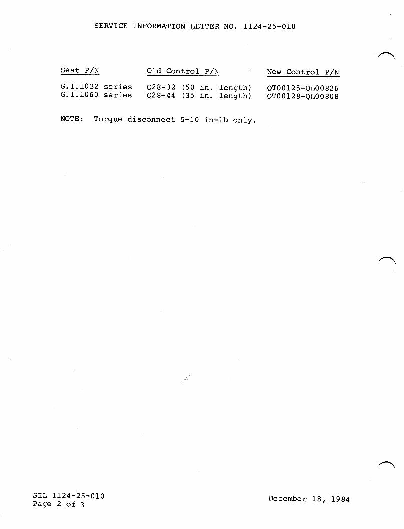
SERVICE INFORMATIOII LETTER NO. 1124-25-010
Seat P/N Old Control P/N
G.1.1032 series e2g-32 (50 in. length)c.1.1060 series e28-44 (35 in. tength)
NOTE: Torque disconnect 5-10 in-1b only.
New Control P/N
Qro012s-QLo0 826Qro0128-QL00808
srl, 1124-25-010Page 2 of 3
December 18, 1984
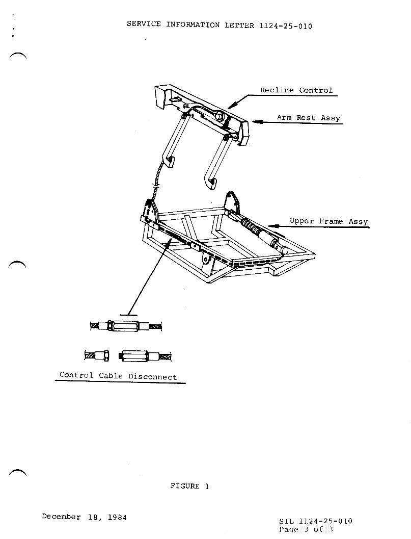
t
SERVICE TNFORMATION LETTER 1124-25.010
Recline Control
Arm Rest Assy
tipper Frame Assy
Control Cable Disccnnect
slL LL24-25-0I0I)acre 3 of 3
December lB, 1984
FTGURE 1
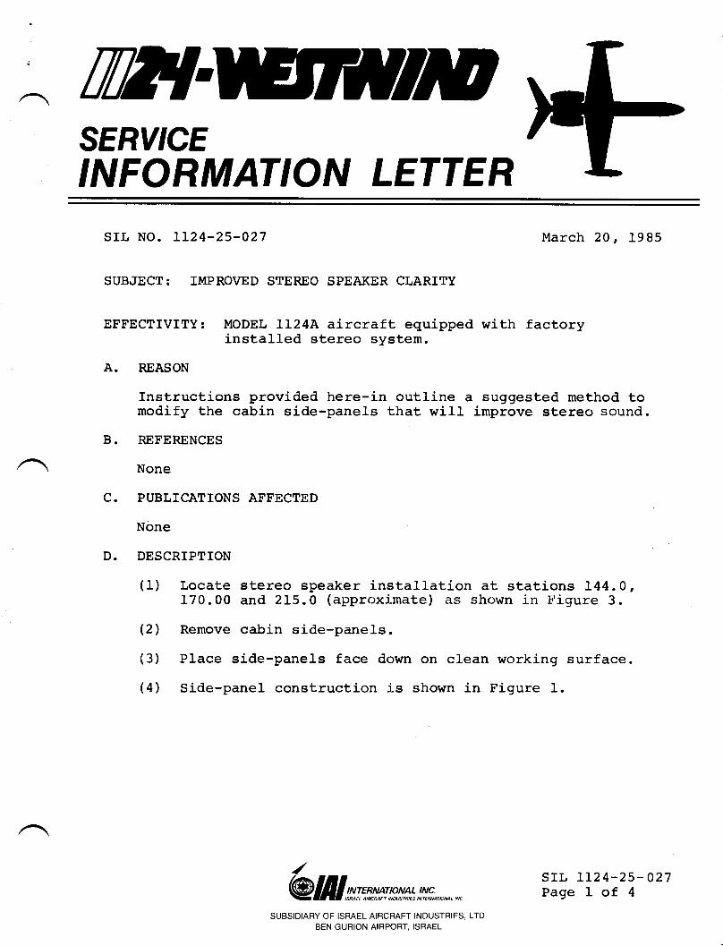
i
TTT!SERY'CEINFORMATION LETTER
srr., No. 112 4-25-027 March 20, 1985
SUBJECT: IMPROVED STEREO SPEAKER CLARITY
EFFECTMTY: MODEL lL24A aircraft equipped with factoryinstalled stereo system.
A. FEASON
Instructions provided here-in outline a suggested method tomodify the cabin side-panels that will improve stereo sound.
B. REFERENCES
None
C. PUBLICATIONS AFFBCTED
None
D. DESCRIPTION
(1) Locate stereo speaker inst,aLlation at stations I44.0,170.00 and 215.0 (approximate) as shown in Figure 3.
(2) Remove cabin side-panels.
(3) Place side-panels face down on clean working surface.
(4) Side-panel construction is shown in Figure I.
/
@ III srms w* l!s;., *,*srl, LL24-25-027Page I of 4
SUBSIDIARY OF ISRAEL AIRCRAFT INDUSTRIES, LTDBEN GURION AIRPORT, ISRAEL
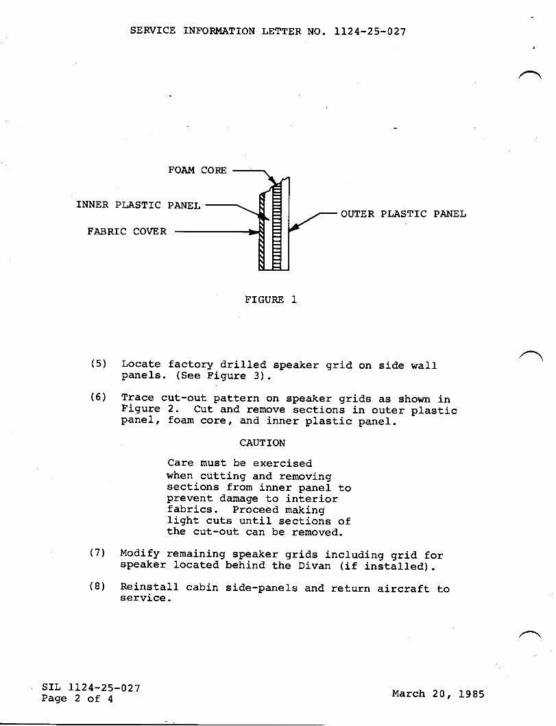
SERVICE INFORMATION LETTER NO. LLz4-25-027
INNER PLASTTC
FABRIC CO\IER
OUTER PLASTIC PA}IEL
FIGURE T
(5) Locate factory drilled speaker grid on side wallpanels. (See Figure 3).
(6) Trace cut-out pattern on speaker grids as shown inFigure 2. Cut and remove sections in outer plasticpanel, foam core, and inner plastic panel.
CAUTION
Care must be exercisedwhen cutting and removingsections from inner panel toprevent damage to interiorfabrics. proceed makinglight cuts until sections ofthe cut-out can be removed.
(7') Modify remaining speaker grids including grid forspeaker located behind the Divan (if installed).
(8) Reinstall cabin side-parrels and return aircraft toservice.
srr, LL24-25-027Page 2 of 4
March 20, 1985

SERVICE INFORMATION LETTER NO. LL24-25-027
l_L/2"r
CUT-OUTAREAS
srr, IL24-25-027Page 3 of 4
3 r/2"
CUT-OUT $jPI:IAKl'll( Glt I l)f.; ((' l'l,A?t,iil')
March 20, 1985
FIGURE 2
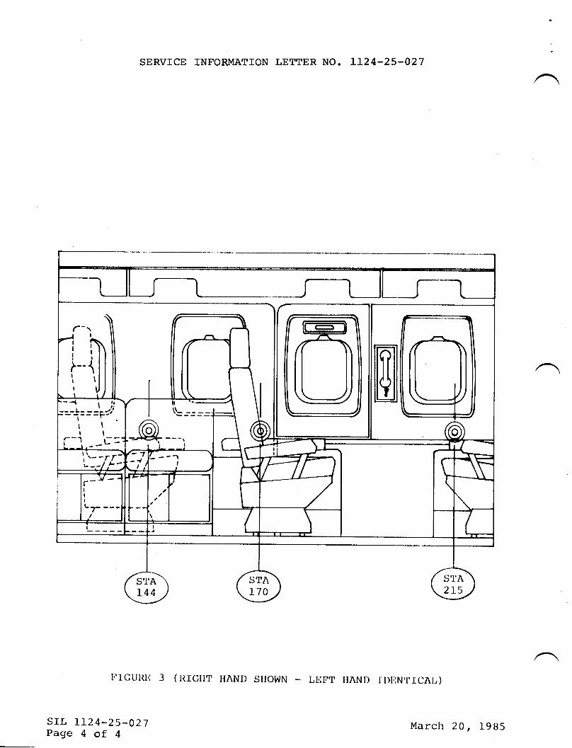
SERVICE INFORMATION LETTER NO. LL24-25-027
Ti.IGUITI.: 3 ( IT.TCIIT IIAND SITOWN LNTT IIAND IDIINTICNL)
srr, II24-25-027Page 4 of 4
@___.
:=-]:III
--1t:
l;l==pr.,'
II
- _tr=
March 20, l9B5
Til?{SERY'CEINFORMATION LETTER
SIL NO. IL24-25-055 June 1-4, 1985
SUBJECT: SHERWOOD TOTLET P,/N 205I TrMER FAILURES
EFFECTTVITY: }IODEL II24 WESTWIND, S/N 187 through 244.
A. REASON
To eliminate the PrlN 2051 timer assembly by providing amanual flushing switch.
B. REFERENCES
None
C. PUBLICATIONS AFF'ECTED
None
D. DESCRIPTION
It is possible to remove the timer assembly and replace it.with a momentary action (normally open) pushbutton switch ofa minimum 5 amp contact rating.You must still close the toilet lid prior to flushing.Switches of many physical dimensions and pushbutton sizesare readily available at any electronic parts wholesalersand are manufactured by all major switch vendors.
Mount your new switch and a "TOILET FLUSH" placard at anyconvenient location on the toilet assembly base. Removetimer and disconnect the red, white and black wires from thetimer terminal block. Connect the new switch (normally opencontacts if you use a double throw switch) to the terminalblock where the BLACK and WHITE wires were removed.
/ srr, 1124-25-055Page 1 of 1
@frlsrmrw*!t!*.,*,*SUBSIDIARY OF ISRAEL AIRCRAFT INDUSTRIES, LTD
BEN GURION AIRPORT, ISRAEL
WTSERY'CEINFORMATION LETTER
u
L.
D.
SIL N0. 1124-25'0598 Auqust 18' 1986
This Service Information Letter No. 1124-25-0598 dated August 18'lgBB supersedes Service Information Letter No. 1124-25-059A datedDecember 2A, 1985 and Service Information Letter No. 1124-25-059dated November B' 1985 in their entirety.
SUBJECT: PORTABLE FIRE EXTINGUISHERS
EFFECTIVITY: tYl0DEL 1124/1124A UESTtTJINDS, aIt serial numbers.
A. REASON
To provide information t,o operators regarding the maintenanceand use of cockpit and cabin fire extinguishers.
REFERENCEs
FAA Advisory Circular No. 2O-42C dated l4arch 7,1984Extinguisher manufacturerfs instructions (extinguisher labeI)
PUBLICATIONS AFFECTED
None
DESCRIPT ION
1. General-
All model aircraft should be equipped r.uith trrlo portablefire extinguishers; one located in the cockpit and one inthe cabin. The extinguishing agent should be either Halon1211 or Halon 1301 . Carbon dioxider uater or dry chemicalextinguishers are not recommended. Hand-held fireextinguishers approved by Underuriters Laboratories or byU.5. Coast Guard under Title 46 of the CFR urill be acceptedby the FAA for use in aircraft. The contained uleight ofHaIon 1211 per extinguisher should be no more than 2.5pounds. Halon 1301 extinguishers should have a minimumrating of 2B: C r tr;ith- the contained rr.reight per extinguisheror no more than
^ @ifrlrr*rrr*rr,!,!!f;.,*.,,*
suBSIDIARY oF IsRAEL AIRcRAFT INDUSTRIES, LrD. 5IL 1124'25- 0598BENGURToNATRPoRT,TSRAEL Paoe 1 of 2
NOTE: The extinguishers referred to above are not U.L. ratedfor CIass A fires (those including normal combustiblematerials such as ulood, cloth, paperr etc.). There isno reason uhy Class A fires cannot be extinguishedutilizing HaIon-type extinguishers. Houlever, if theyprove ineffective (such as in the case of a smolderinqseat cushion, for example), ulater carried from thelavatory or application of non-alcoholic beveragesthat may be available rrrilt aid in extinguishing thefire .
Toxicity
Halon 1211 and Halon 1301 are considered lor,r-toxicityextinguishing agents. Hotrlever, exposure to highconcentrations even for short periods of time can producedizziness, impaired coordination and reduced mentalsharpness, hence the maximum agent rrreight recommendationsin 1. above. There are no knouln lasting effects fromexposure to these agents.
ldhen Haron 1211 or 1301 is discharged onto a fire, itdecomposes and rereases haride ions (tne extinguishingagent). rn addition, other harogen compounds are formedtrrhich are considered toxic. The amount of toxic comooundsformed depends on the size of the fire, but these should beconsidered far less hazardous than those produced by thefire itself.To summarize, the danger from fire and associated smoke,fumesr oxyqen depletion and carbon monoxide generation ismuch.greater than that caused by exposure to Halon1211 /13O1 or its decomposition products.
Placards
If the fire extinguisher is not rocated urhere it can beseen' a hiqhly visibre placard should be provided.
wlaintenance
SERVICE INFORMATION LETTER NO. 1124-25-0598
rnspect extinguishers monthry for corrosion, damage orIou reading on pressure gauge.
ldeigh extinguishers every six ( 6 ) months. Recorduleight on maintenance tag. Replace or recharge if theureight falls belou the Iimit specified on theextinguisher labeI.Pressure test every trrrelve (1r2) years, preferably bythe manufacturer.
2.
3.
4.
(")
(b)
(")
sIL 1124-25-0598Page 2 of 2
August 18, 1986
TWTSERY'CEINFORMATION LETTER
This sheet transmits Revision 1 to Service fnformation Letter No.1124-25-059, dated November 8r 1985, titled "Portable FireExtinguishers. "
REASON FOR REVTSTON:
This service information letter is revised to correct and addinformation regarding maintenance of portable fire extinguishers.
Paragraph D.4. - Maintenance is revised in its entirety.
This service bulletin is reissued in its entirety. Please removeand discard all pages of previous issues and replace with pagesof this issue.
LIST OF EFFECTIVE PAGES
srl, No. 1124-25-059 REVISTON-1
TRANSMITTAL SHEET
JuIy 31, 1989
Page No.
1 July 31, 1989July 31,1989July 31, 1989
PREVIOUS REVISIONS:
1124-25-0594 dated December 20, 19851124-25-0598 dated August 18, 1986
Date
23
/
@ lI I srnss p** t !,!ffi ., *.,, *SUBSIDIARY OF ISRAEL AIRCRAFT INDUSTRIES, LTD.
BEN GURION AIRPORT, ISRAELTRANSMITTALPage 1 of 1
November 8, 1985
TilT{SERY'CEINFORMATION LETTER
srl, No. 1124-25-059
SUBJECT:
EFFECTIVITY:
A. REASONS
To provi-deand use of
B. REFERENCES
NovemberRevision
November 8' 1985
PORTABLE FIRE EXTTNGUISHERS
MoDEL 1124/ltzql WESTWTNDS, all serial numbers.
information to operators regarding the maintenancecockpit and cabin fire extinguishers.
RRR
R
FAA Advisory Circular No. 20-42C dated March 7, 1984.Extinguisher manufacturer t s recommendations.Code of Federal Regulations, Chapter 29, Section 1910.157(e).Code of Federal Regulationsr Chapter 49, Section173.306(c)(5).
C. PUBLTCATIONS AFFECTED
None.
D. DESCRTPTION
1. General
A11 model aircraft should be equipped with two portablefire extinguishers, one located in the cockpit and onein the cabin. The extinguishing agent should be eitherHalon 1211 or Halon 1301. Carbon dioxide, water or drychemical extinguishers are not recommended. Hand-he1dfire extinguishers approved by Underwriters Laboratoriesor by U.S. Coast Guard under Title 46 of the CFR will beaccepted by the FAA for use in aircraft. The containedweight of Halon 12'11 per extinguisher should be no morethan 2.5 pounds. Halon 1301 extinguishers should have aminimum rating of 2BzC, with the contained weight perextinguisher of no more than 4 pounds.
@ III gr:xgrw*t !,!!,fi n *.,,*
/
8,1,
1 91 5 SUBSTDTARY OF TSRAEL ATRCRAFT TNDUSTRTES, LTD
JuIy 31 , 1 989BEN GURIoN AlRPoRr' ISRAEL
srl, 1124-25-059Page 1 of 3
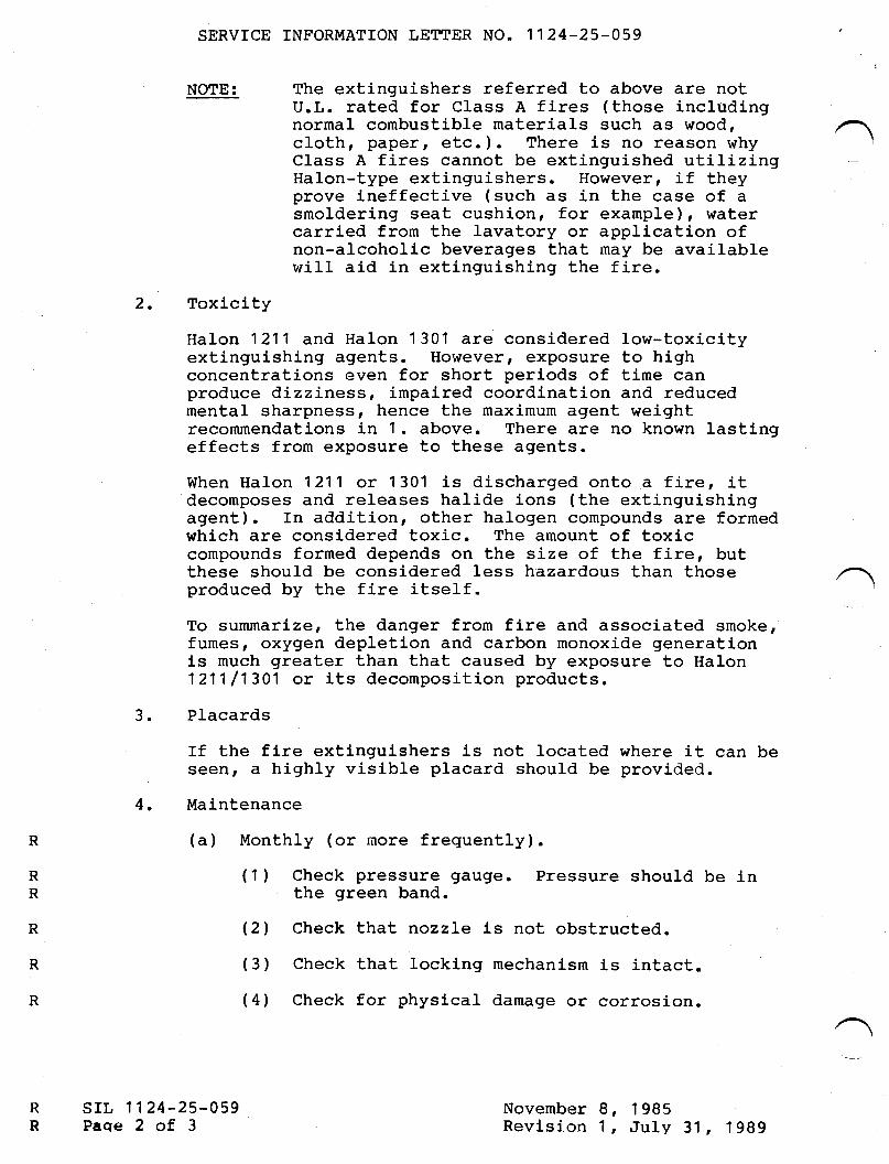
NOTE:
srL 1124-25-059Paqe 2 of 3
(1 ) Check pressure gauge.the green band.
Pressure should be in
SERVTCE INFORMATTON LETTER NO. 1124-25-059
The extinguishers referred to above are notU.L. rated for Class A fires (those includingnormal combustible materials such as wood,cloth, paper, etc. ). There is no reason whyClass A fires cannot be extinguished utilizingHalon-type extinguishers. However, if theyprove ineffective (such as in the case of asmoldering seat cushion, for example), watercarried from the lavatory or application ofnon-alcoholic beverages that rnay be availablewill aid in extinguishing the fire.
-
2. Toxicity
Halon 1211 and Halon 1 301 are considered low-toxicityextinguishing agents. However, exposure to highconcentrations even for short periods of time canproduce dizziness, impaired coordination and reducedmental sharpness, hence the maximum agent weightrecommendations in 1. above. There are no known lastingeffects from exposure to these agents.
When Halon 1211 or 1301 is discharged onto a fire, itdecomposes and releases halide ions (the extinguishingagent). In addition, other halogen compounds are formedwhich are considered toxic. The amount of toxiccompounds formed depends on the size of the fire, butthese should be considered less hazardous than thoseproduced by the fire itself.
To summarize, the danger from fire and associated smoke,fumes, oxygen depletion and carbon monoxj-de generationls much greater than that caused by exposure to Halon121'l /1301 or its decomposition products.
Placards
If the fire extinguishers is not located where it can beseen, a highly visible placard should be provided.
Maintenance
(a) Monthly (or more frequently).
3.
4.
RR
(21 Check that nozzle is not obstructed.
( 3 ) Check that locking mechanism is intact.(4) Check for physlcal damage or corrosion.
R
RNovemberRevlsion
1 98sJuly 31,1989
I,1,
SERVICE INFORMAIION LETTER NO. 1124-25.059
R (b) yearly.
R (1 ) weigh unit and record welght on maintenanceR tag.
R (21 Replace or recharge if the weight falls belowR the tlmlt speclfied on the extlngulsher label.R (c) Every six years.
R (1) Discharge unit, overhaul va1ve, and refill perR manufacturerts maintenance instructionsR (preferably by manufacturer).R (d) Every twelve years.
R (1 ) Perform hydrostatic test on cylinderR (preferably by manufacturer).
R November 8, 1 985R Revision 1, July 31r 1989
srl, 1124-25-059Page 3 of 3
SERY'CEINFORMATION LETTER
SERVICE INFORMATION LETTER NO. 1124-25496 JuIy l,1992
SUBJECT: EQUIPMENT/FURNISHINGS - EXTENDED OVER WATEROPERATIONS, SAFETY AND SURVIVAL EQIIIPMENT
EFFECTIVITY: MODEL lL24lll24A WESTWIND, all serial numbers.
A. REASON
To emphas ize theimportance of preflight preparation for extended over water
flights.
B. REFERENCE
Civil Air Regulation (CAR) Part 4b.
Federal Aviation Regulation (FAR) Part 91 and 135.
C. PI]BLICATIONS AFFECTED
None.
D. DESCRIPTION
This Service Information Letter is intended to serve as a reminder to operators
that a passenger briefing (FAR 91.519 and 135.117) shall be conducted prior toextended over water flights. Safety equipment shall be readily accessible to the
flight crew (CAR 4b.646), and life preservers within easy reach [CAR 4b.646(d)]
of each seated occupant. Furttrer requirements may be found in Civil AirRegulations (CAR) Part 4b.
sL 1t24-25-096Page 1 of 1
July 1, 1992
tw{SERY'CEINFORMATION LETTER
srl, No. II24-27-002 November 9, 1984
SUBJECT: FLAP ASSYMI,IETRY COMPARATOR CONTROL BOX FAILURES ANDNUISANCE TLAP IMBALANCE !'ilARNINGS
EFFECTIVITY : MODEL Ll24/LI24A AIRCRAFT, SERIAL NUIIIBER ]-52,L54, 174, 181, I85 through 396.
A. REASON
To introduce an approved replacement Control Box to:
(f) Eliminate Control Box failures due to electrical systemtransient voltages.
(2) Reduce imbalance warnings caused by Flap PositionTransmitter and other system noises.
NOTE
The information containedin this Service InformationLetter will NOT compensatefor improperly adjusted ordefective Flap PositionTransmitters.
B. REFERENCES
LI24 Maintenance Manual, Chapter 27.
C. PUBLICATIONS AFFECTED
LL24/LI24A lllustrated Parts Cataloqr.
/@ lI I grnxg mn * !,!!u";., o..,, *
srl, 112 4-27-002Page I of 3
SUBSIDIARY OF ISRAEL AIRCRAFT INDUSTRIES, LTD
BEN GURION AIRPORT, ISRAEL
November 9, 1984
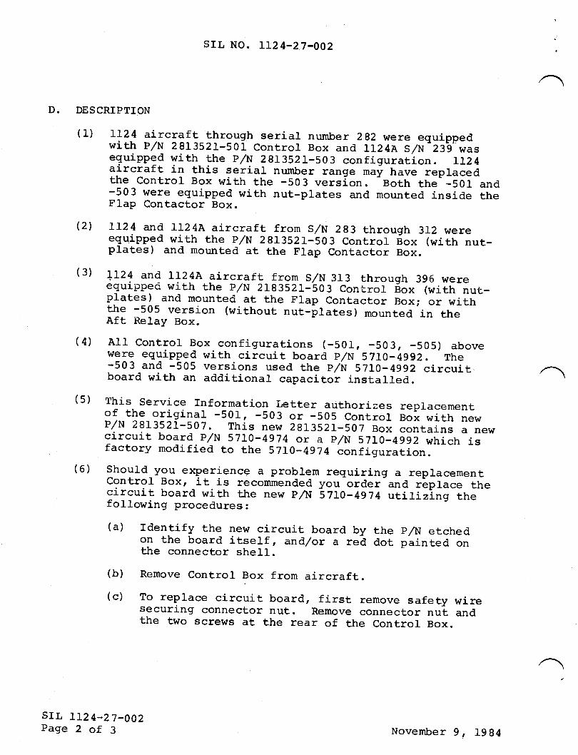
srl, NO. 1124-27-002
D. DESCRTPTION
(1) rr24 aircraft through serial number 2g2 were equippedwith p/N 2BL3s21-501 controt Box and 1124A s/N 239 wasequipped with the p/N 2813521-503 configuration. rL24aircraft. in this serial number range maf have repracedthe Control Box with the -503 version. Both the -50I and-503 were equipped with nut-plates and mounted inside theFlap Contactor Box.
(2) Lr24 and rr24A aircraft from s/N 2g3 through 3r2 wereequipped with the e/N 2913521-503 contror sox (with nut-plates) and mounted at the Flap Contactor Box.
(3) u2+ and r124A aircref!- lrgry s/N 3r3 rhrough 396 wereequippec with the p/N 2rg352r-'so3 cont.rol iox (with nut.-plates) and mounted at the Flap contactor Box; or wi_ththe -505 version (without nut_plates) mounted in theAft Relay Box.
(4) A11 control Box configurations (-501, -503, -505) abovewere equipped with circuit board p/N 5zto- 4992. The-503 and -505 versions used the p/N 5710- 4gg2 circuit.board with an additional capacitor installed.
(5) This Service rnformation Letter authorizes replacementof the_originar -501, -503 or -sos control Box with newP/N 2813521-507. This new 2813521-507 Box contains a newcircuit board P/N 57Io-4974 or a p/N s'tlo- giz wrrictr isfactory modified to the sTro-4974 configuration.(6) should-you e>rperience a problem requiring a replacementcontrol Box, it is reconmended you order and rlprace thecircuit board with the new p/N E 7Lo-4g74 utilizing thefollowing procedures:
(a) rdentify the new circuit board by the p/N etchedon the board itself, and/or a red dot painted onthe connector sheIl.(b) Remove Control Box from aircraft.(c) To replace circuit board, first remove safety wire
securr-ngf connector nut. Remove connector nut andthe two screws at the rear of the Control Box.
srr, 112 4-27-OO2Page 2 of 3 November 9, 1984
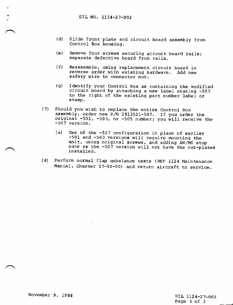
,srL No. 112 4-27-002
(d) slide front plate and circuit board assembry fromControl tsox housing.
(e) Remove four screws securing circuit board rails;separate defective board from rails.
(f) Reassemble, using replacement circuit board inreverse order with existing hardware. Add newsafety wire to connector nut.
(g) rdentify your control Box as containing the modifiedcircuit board by attaching a new label stating -507to the righL of the existing part number 1abe1 orstamp.
(7') Should you wish to replace the entire Control Boxassembly, order new p/N 29L3521-507. rf you order theoriginal -501, -503, or -505 number; you wirr receive the-507 version.
(a) use of the -507 configuration in place of earlier-501 and -503 versions'wi11 require mounting theunit, using original screws, and adding AN,/MS stopnuts as the -507 version will not have the nut-plltesinstalled.
(8) Perform normal flap unbalance tests (nnf 1124 MaintenanceManual, Chapter 27-50-00) and return aircraft to service.
srl, 112 4-27-OO2Page 3 of 3
November 9, 1994

SERVICE PUBLICATIONS
re\rision notice(p"rnwd rA\ 77, t?I0
srl, No. LL24-27-028Revision No.1
SUBJECT: FI,AP LIMIT SWITCH REPI,ACEMENT
ilune L4, 1985
REASON FORREVISION: To change a part nunber in paragraph 6 and a
IrtIL Spec number in paragraph 9.
6. Apply a coat of red enamel glyptal 1201(insulating paint) on the switch mounting area.
9. App1y MIL-S-8802 potting compound on allelectrical wire connections. Reinstall coverusing retained hardware.
SB Ll24-27-028/ Pagetrofl@Wwrmm**
SUSSIOIARY OF ISRAEL ATFICRAFI INOUSTFIES, LTO8EN OURION AINPOR', ISRAEL
IHSERY'CEINFORMATION LETTER
srr, No. Lr24-27-028 REVISION 1 May 29, L990
SUBJECT: FI-AP LIMIT SWTTCH REPI.ACEMENT
CAf'{ CELLATI O N NOTI CE
This service information letter is hereby canceled. The information contained in this SILhas been incorporated into the ll24 Westwind Maintenance Manual, Chapter n-50-00.
April24,L985Revision 1, May 29,1990
sILLr24-n-028Page 1 of 1
t
i TWTSERY'CEINFORMATION LETTER
srl, No. IL24-27-028
SUBJECT: FLAP LIMIT SWITCH REPLACEII4ENT
@ III sr**sp*n* !,!Y;.,*,,n
,fd'l.lay 16, 1985
SIL IL24-27-028APage I of 2
A.
B.
c.
EFFECTIVITY: IL24/LL24A WESTWINDS, all serial numbers.
REASON
Provide instructions for field replacement of flap limitswitches.
REFERENCES
None
PUBLICATIONS AFFECTED
LL24 Illustrated Parts Catalog.
LL24 Maintenance Manual, Chapter 27-50-00.
DESCRIPTION
1. Remove flap limit switch assemblies as per LL24Maintenance Manual Chapter 27-50-00.
2. Remove cover from limit switch assembly and retain hard-ware for reinstallation.
NOTE
The left assemblyconsists of sixactuating switches.The right assemblyconsists of twoactuating switches.
D.
/
SUBSIDIARY OF ISRAEL AIRCRAFT INDUSTRIES, LTDBEN GURION AIRPORT, ISRAEL
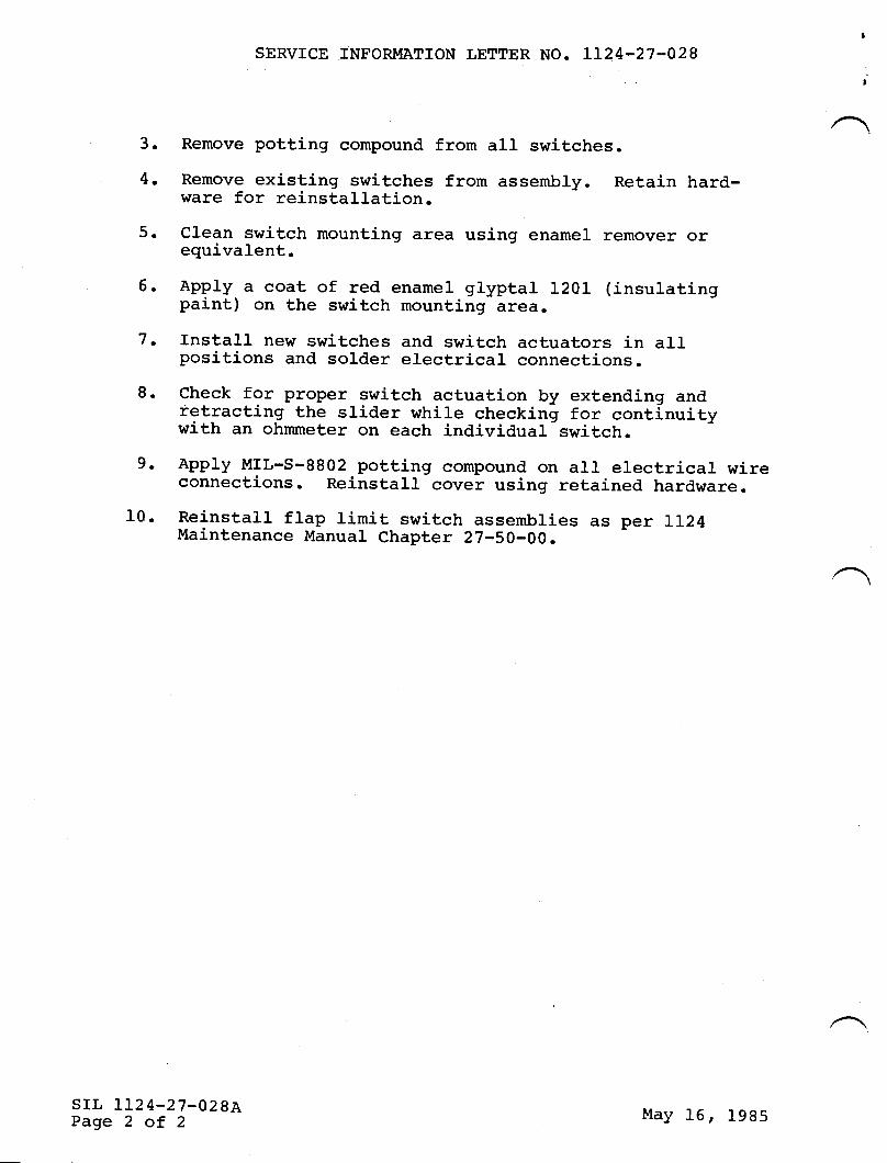
SERVICE INFORMATION LETTER NO. LL24.27-028
3. Remove potting compound from all switches.
4. Remove existing sr^ritches from assembly. Retain hard-ware for reinstallation.
5. clean switch mounting area using enamel remover orequivalent.
5. Apply a coat of red enamel glyptal 1201 (insulatingpaint) on the switch mounting area.
7. Install new switches and switch actuators in allpositions and solder electrical connections.
8. check for proper switch actuation by extending andretracting the srider while checking for continuitywith an ohmmeter on each individual-switch.9. Apply MrL-s-8802 potting compound on arl electrical wireconnections. Reinstarl cover using retained hardware.
10. Reinstall flap limit switch assembries as per Ll24Maintenance Manual Chapter 27-50-00.
srr, 1124-27-028APage 2 of 2
May 16, 1985
tilflSERY'CEINFORMATION LETTER
srl, No. lru-n-$0 REVISION 1 M;ay 29, L990
SUBJECT: MEASUREMENT LIMITS OF AILERON TRIM,AND SERVO TABFREEPI-AY
CAT{CELI,ATION NOTICE
This service information letter is hereby canceled. The information contained in this serviceinformation letter has been incorporated into the ILV| Westrrind Maintenance Manual,Chapter 27-L0-0{J.
March 20,L985Revision 1, May 29,1990
$LtLU-27-030Page 1 of 1
1 IWTSERY'CEINFORMATION LETTER
srr, No . LL24-27-O3O *rfcn
March 20, 1985
AILERON TRIM AND SERVO TABSUBJECT: MEASUREMENT LTMITS OFFFAEPLAY
EFFECTIVITY: LL24/LL24A WESTWINDS, all serial numbers.
A. REASON
To establish aileron trim and servo tab freeplay limtsand provide instructions for measuring freeplay.
B. REFERENCES
None
C. PUBLICATIONS AFFECTED
Instructions and limits outlined in this Service InformationLetter will be included in the next scheduled revisionto the LL24/LL24A Maintenance Manual.
D. DESCRIPTION
NOTE
The location for freeplaymeasurements are identicalfor both the trim tab andservo tab (with exceptionof the freeplay limitdifferences) .
(1) Place dial indicator measuring point at trailing edgeof tab 5 inches from outboard edge. Zero indicator.
/@ III grmslp*t* !J!n';.,*,,*
SUBSIDIARY OF ISRAEL AIRCRAFT INDUSTRIES, LTD.BEN GURION AIRPORT. ISRAEL
srl, IJ.24-27-030Page 1 of 3
SERVICE INFORMATION LETTER NO. LI24-27.030,t
(2) Apply upr/down force of I pound to tab trailing edgeadjacent to the dial indicator illeasurement point.
(3) Note tab freeplay. Limits should not exceed:
Aileron Trim Tab (tH) = 0.085 inch.Aileron Servo Tab (RH) = 0.043 inch,
(4) rf freeplay'exceeds stated limits, check alr rod-endsand bolts installed for wear. Replace worncomponents as required.
srr, 112 4-27-030Page 2 of 3
l'larch 20, 1985
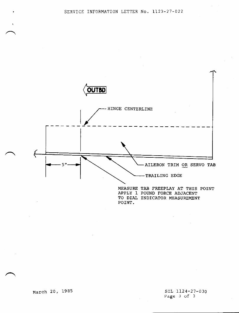
SERVICE INFORMATION LETTER No. 1123-27-022
HINGE CENTERLINE
I
( OI,TBDI
,r/
r,,,--lAILERON TRIM OR SERVO TAB
TRAILING EDGE
MEASURE TAB FREEPLAY AT THTS POINTAPPLY 1 POT'ND FORCE ADJACENTTO DIAL ]NDICATOR MEASUREMENTPOINT.
srL LIz4-27-030Page 3 of 3
March 20, I9B5
TWTSERY'CEINFORMATION LETTER
srr, NO. LL24-27-057
SUBJECT:
EFFECTIVTTY:
RUDDER AND TABS
MODEL LI24/IL24A,
September 16, 1985
SYNCHRONIZATION OF DUAL ACTUATORS
all serial numbers
A. REASON
To provide. operators with advanced information on traveltolerances for checking synchronization of dual rudder trimtab actuators that will appear in a future revision of theLI24 Maintenance Manual.
REFERENCES
Model IL24/II24A Maintenance Manual, Chapter 27Model IL24/LL24A Wiring Diagram Manual, Chapter 27
PUBLICATIONS AFFECTED
Model IL24/IL24A Maintenance Manual, Chapter 27, will berevised to reflect synchronization checks of the rudder trimtab actuators.
DESCRIPTION
1. Travel tolerance of dual rudder trim tab actuators havebeen changed to better coordinate the movement of thetwo actuators and prevent tab warpage.
2. when changing only one actuator, it may be beneficial tocheck the remaining actuator for compliance with the newreguirements and insure proper synchronization.
3. Refer to Moder rL24/Lr24A Maintenance Manual, chapter27-20-00 for actuator removal and reinstallation.
4. Refer to Model IL24/II24A Wiring Diagram Manual forelectrical hook-up.
B.
c.
D.
/srr. II24-27-057Page 1 of 2
@ II I s::ms p*n: !,!#;, * n,, *SUBSIDIARY OF ISRAEL AIRCRAFT INDUSTRIES, LTD
BEN GURION AIRPORT, ISRAEL
SERVICE INFORMATION LETTER NO. LL24-27-057
5. Mount actuator in a fixture capable of applying 150 Ibsof load on the "extend and retract" position of theactuator.
6. Apply 28 Vdc at 1.5A and operate actuator to extend andretract and check tolerances as follows:
Travel Distance z .425 to .430 inchTravel Speedt 27 to 29 seconds, one way
7. Actuators may arso be returned to Atlantic Aviation forcheck.
8. Actuators found out-of-adjustment should be returned toAtlantic Aviation for adjustment.
srl, LI24-27-057Page 2 of 2
September 16, I9B5
TEISERY'CEINFORMATION LETTER
A.
B.
srr, No. LI24-27-063 February 7 | 1986
SUBJECT: TO ANNOUNCE THE AVAILABILITY OF A NEW EMI FILTER
EFFECTIVfTY: MODEL II24/II24A WESTWINDS, a1l serial numbers.
REASON
The filter presently installed on the horizontal trimactuator is prone to shorts,/open and may be a cause ofprimary motor failure.
REFERENCE
None.
PUBLICATIO}IS AFFECTED
None.
DESCRIPTION
An improved horizontal trim EMf filter has been developedto improve actuator performance. Overhaul agencies havebeen informed of improved filters for incorporation in newoverhauls.
D.
/ srl, II24-27-063Paqe I of I
@ lI I srw e** !,!s;, *.,, *SUBSIDIARY OF ISRAEL AIRCRAFT INDUSTRIES, LTD
BEN GURION AIRPORT, ISRAEL
tilE{SERY'CEINFORMATION LETTER
SUBJECT:
EFFECTIVITY:
HORIZONTAL TRIM ACTUATOR - AXIAL PLAY
MODEL LI24/LL24A WESTWINDS, all serial numbers.
A.
B.
(-
D.
REASON
To provide operators withinformation on axial playtrim actuator rods.
REFERENCES
advanced maintenance manuaitolerances for the horizontal
None.
PUBLICATIONS AFFECTED
LI24/LI24A Maintenance Manual, Chapter 27-40-00 will berevised to reflect added tolerance information.
DESCRIPTION
When performing the "Adjustment,/Test" portion ofmanual instructions, check the axial free play of.000 to .009 inch excluding rod-end fitting.
maintenancerods to
srl, 112 4-27-064Paqe I of I
/@lfllsrxswn*ffi.,*,*
SUBSIDIARY OF ISRAEL AIRCRAFT INDUSTRIES, LTD.
BEN GURION AIRPORT, ISRAEL
TilHSERVICEINFORMATION LETTER
SMYICE INT'ORMATION LETTER NO. 1 124-27 -IO7 December 14.1994
FLIGHT CONTROLS - RIGHT INBOARD FLAP FLEXIBLEDRIVE SHAFT ROUTING
MODEL ll24llt24{ WESTWIND. all serial numbers.
SU&IECT:
E.FTECTWTIY:
A. REASON
December 14, 19941084
To insure adequate inspection for proper flap inboard flexible drive shaftrouting during maintenance of flexible drive shafts or routine inspections.
B.REFERENCE
lI24lLl24A Westwind Maintenance Manual. 5-20-05 and 27-50-00.
C. PUBLICATIONS AFFECTED
None.
D. DESCRIPTION
One instance of undetected interference between the right inboard flap flexibledrive shaft assembly and the aileron autopilot servo capstran arm has been
reported. Evidence of chafing contact between the forward edge of the aileronautopilot servo capstan arm and the flexible drive shaft housing was noted.
During routine maintenance of the flap flexible drive shaft installation orgeneral visual inspection of the fuselage station 316 area, proper flexible driveshaft routing must be verified. Improper flexible drive shaft routing and
resultant interference with adjacent equipment is possible by inverting flexibledrive shaft mounting clamps during installation.
A thorough inspection of the area is advised during flap flexible drive shaft
removal/installation, and during routine inspections of all equipment mounted
on or near fuselage station 316. Reference II24lIl24A WestwindMaintenance Manual, 27-50-00, Servicing and Removalilnstallation, and
5-20-05. Maintenance Practices.
sII- 1t24-27-107Page 1 of 1

n2lSERY'CEINFORMATION LETTER
SIL NO. IL24-28-009 December 13, 1984
SUBJECT: WING FUEL PROBE GASKET, LEFT AND RIGHT OUTBOARD.
EFFECTIVITY: I{ODEL 1L24, serial number 187 through 258.
REASON
To announce the availability of a new 653054-533 gasket thatwill increase the clearance and prevent contact between thewing fuel probe P/N 653505-507 and upper wing skin.
REFERENCES
IL24 IPC, Chapter 28-40-00, Figure 3, Item 29A.
PUBLICATIONS AFFECTED
A.
B.
c.
D.
7124 IPC, Chapter 28-40-00,revised to reflect the new
DESCRIPTION
Figure 3, Item 29A, will be653054-533 gasket.
The new 653054-533 gasket is thinner than the 553054-505gasket and,prevents fuel probe contact (and possible shorting)with the upper wing skin.
/@ lI I y;::mg !."xn* !,!!s;., ^.,, *
srr, LL24-28-008Page 1 of 1
SUBSIDIARY OF ISRAEL AIRCRAFT INDUSTRIES, LTD
BEN GURION AIRPORT. ISRAEL
rilIISERY'CEINFORMATION LETTER
SIL NO. lI24-28-020A APril 30, L987
(This Service Information Letter No. LL24-28-020A dated April 30,198?, supersedes Service Information Letter No. LL24-28-O2O datedMarch 28, 1985 in its entirety.)
A.
SUBJECT: FUEL DUMP VALVE INTERCHANGEABILITY
EFFECTMTY: MODEL LL24/LL24A WESTWINDS, all serial numbers.
R E ASON
To permit interchangeability of fuel dump valve part numbers653014-1 and 653014-501.
RE F ERENC ES
None.
PUBLICATIONS AFFECTED
LL24ltL24A Illustrated Parts Catalog, Chapter 28-30-00 will berevised to reflect the availability of P/N 653562-27 bracket.
D ES CRIPTION
The referenced fuel dump valves differ in width by .25O". Toallow interchangeability, P/N 653562-L3 or 653562-23 checkvalve mounting brackets are replaced with two 653562-27brackets. The replacement brackets are slotted to allow the653562-I, -501 check valve to be shifted forward or aftsufficiently to al1ow either style dump valves to belnstalled. It is recommended that this modification (Figure 1)be accomplished at the next dump valve replacement.
B.
c.
D.
I
/ srl, LL24-28-020APage 1 of 2@ lfil s*xstp*t* !#;,*^,*
SUBSIDIARY OF ISRAEL AIRCRAFT INDUSTRIES, LTD
BEN GURION AIRPORT, ISRAEL
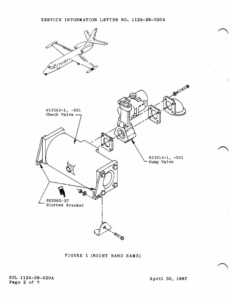
SERVICE INFORMATION LETTER NO. LL24-28-O2OA
653562-L, -501Check Valve
653562-27Slotted Bracket
srL Lr24-28-020APage 2 of 2.
653014-1, -501Dump Valve
,^..(J?-
FIGURE 1 (RIGHT HAND SAME)
April 30, L987
THSERY'CEINFORMATION LETTER
SIL NO. LL24-29-026 Ivtarch 20, 1985
SUBJECT: REPLACEMENT OF FIREWAIL FUEL SHUT-OFF VALVE LIGHTCIRCUIT RELAY
EFFECTIVITY: MODEL LL24/LL24A WESTWINDS, serial numbers f87and subs.
A. REASON
To avoid failure of indicator light circuit when fuelshut-off valve light diodes fail.
B. REFERENCES
LL24/LL24A Illustrated Parts Catalog, Chapter 28.
C. PUBLICATIONS AFFECTED
None
D. DESCRIPTION
Part number 653572-501 diode failure in the fuel shutoffvalve indicator light circuit usually causes damage to theM527401-14 test light re1ay. It is therefore recommendedto replace the MS27401-14 test light relay whenever theFirewall Shut-Off Valve P/N 6753572-50L is replaced.
/ srr, IL24-28-026Page 1 of I@ lill srmstp*t* !Js;.,*,*
SUBSIDIARY OF ISRAEL AIRCRAFT INDUSTRIES, LTD.
BEN GURION AIRPORT, ISRAEL
TW{SERY'CEINFORMATION LETTER
srL No. IL24-28-052 February 7, 1986
SUBJECT: TO ANNOUNCE THE AVAILABILITY OF A NEW FUEL VENT VALVE
EFFEcrrvrrY: MODEL rr24/rr24A wEsrwrNDS, alt- serial numbers.
A. REASON
Some operators have experi-enced difficulty with the fuel ventcheck valves sticking, allowi-ng fuel to vent overboard.
B. REFERENCES
II24/IL24A Maintenance Manual, Chapter 28-10-00.
C. PUBLICATIONS AFFECTED
rr24/1r24A rllustrated parts cataloq will be revised toreflect new part numbers
D. DESCRIPTION
An improved fuel vent check varve has been developed toreplace present check valve P,/N 653760-1 located in the wingand tip tanks. l'Iew P/N is 3653807-501 and may be purchasedfrom Atlantic Aviation supply company, wilmington, Delaware.Refer to rr24/LL24A Maintenance Manual, chapter 2g-r0-oo forremoval and installation.
srl, Lt24-28-062Page I of I
@lillwm*p*t*!#;,*^,*SUBSIDIARY OF ISRAEL AIRCRAFT INDUSTRIES, LTD
BEN GURION AIRPORT, ISRAEL
TWTSERY'CEINFORMATION LETTER
SER,VICE INFORMATION LETTER, NO. 1124.28-0po March 13, 1991
SU&IECT: FUEL - FUEL DUMP STOP LEVEL SWTTCH PRECAUTIONS
EFTECTIVITI: MODELS Ll24llL24A WESTWINDS, d serial numbers.
A. REASON:
Recently an ll24 Westwind aircraft had to dump fuel before landing. Thesystem did not stop dumping automatically due to shorted wires at the float switchconnection.
B. REFERENCE:
lI24lLl24A Westwind Maintenance Manual, Chapter 28-20-ffi and 28-30{0.
C. PUBLICATIONS AFFECTED:
Lt24lI124A Westwind Maintenance Manual, Chapter 28-2040 and 28-3040.
D. DESCRIPTION:
When maintenance necessitates removal of either the transfer start level switch orfuel dump stop level switches, maintenance personnel should ensure that wiringrouted in conduit to these switches is free from shorts to ground and that theswitches operate properly. Proper operation of the switch can be checked byensuring the circuit to the switch is open when less than 900lbs. of fuel is in the
tank and closed with more than 1000lbs.
March 13, 1991
1035
srL rt24-28490Page 1 of 1
}{e
6
TTT]SERVICEINFORMATION LETTER
srl. No. 1124-28-103 REVISION 1
TRANSMITTAL SHEET
JuneZ2,1994
This transmits Revision 1 to Service Information Letter No. 1124-28-103 dateA
May 25,1994 titled, "Fuel - Improved Fuel Boost Pump."
REASON FOR REVISION
To correct Fuel Boost Pump part number to 653744-507 and 653744.
This is a COMPLETE REVISION, replace all pages affected by this revision.
LIST OF EFFECTIVE PAGES
PAGE NO. DATE
June2Z, 1994
PREVIOUS REVISIONS OF SIL 1125-32449
None.
TransmittalPage I of 1
June22. 1994
TTT]SERVICEINFORMATION LETTER
RR
SERVICE INFORMATION LETTER, NO. 1124-28-103 May 25, 1994
SUBJECT: FUEL - IMPROVED FUEL BOOST PUMP
EFFECTIVITY: MODEL Ll24ll124A WESTWIND, with Intertechnique FuelBoost Pumps.
A. REASON
To advise operators of availability of an improved Fuel Boost Pump
P/N 653744-507 which is a direct replacement for Intertechnique Fuel BoostPumps P/N 653744 (all dash numbers).
B. REFERENCE
None
C. PUBLICATIONS AFFECTED
ll24ll124A Westwind Illustrated Parts Catalog, Chapter 28-2040.
)ND. DESCRIPTION
Fuel Boost Pump P/N 653744-507 is an alternate replacement which can be
installed in any position that an Intertechnique Boost Pump is currently installed.Pumps may be installed individually with no airframe modification required.
The alternate replacement pumps are being offered for their improved reliabilityand are available from Astra Jet Corporation.
R
May 25,1994R Revision l, June 22, 1994
1068sL 1124-28-103
Page I of I
IJ TW]
SERY'CEINFORMATION LETTER
SERVICE INFORMATION LETTER NO. 1124.28.103 May 25, L994
SUBJECT: FUEL.IMPROVED FUEL BOOST PUMP
EFFECTIVITY: MODEL llz4lllz4AWESTWIND, with Intertechnique FuelBoost Pumps.
A. REASON
To advise operators of availability of an improved Fuel Boost PumpP/N 567344-507 which is a direct replacement for Intertechnique Fuel BoostPump P/N 567344 (all dash numbers).
B. REFERENCE
None
C. PUBLICATIONSAFFECTED
| 124 I 1,724 A Wes twi nd Illustrate d Parts Catalog, Chapt er 28-20-00.
D. DESCRIPTION
Fuel Boost Pump P/N 567344-507 is an alternate replacement which can beinstalled in any position that an Intertechnique Boost Pump is currentlyinstalled. Pumps may be installed individually with no airframe modificationrequired.
The alternate replacement pumps are being offered for their improvedreliability and are available from Astra Jet Corporation.
May 25,19941068
srL1t24-28-103Page 1 of 1
tilE{SERY'CEINFORMATION LETTER
A.
SrL NO. 1124-29-051 May 27, 1985
SUBJECT: HYDRAULIC POWER - EMERGENCY HYDRAULIC PUMP SHAFTSEAL DRAIN FITTING - PROPER INSTALLATION INSTRUCTTONS
EFFECTIVITY: MODEL LI24 WESTWIND, all serial- numbers.
REASON
To announce the availability of "installation instructions"for the emergency hydraulic pump shaft seal drain fittingthat is scheduled to be incorporated in the next revision ofthe ]-]-24 maintenance manual.
REFERENCES
None
PUBLICATIONS AFFECTED
Section III of the L]-24 Series Maintenance Manual.
DESCRIPTTON
The following precautions must be taken when installing theshaft seal- drain fitting, P/N ItlS20823-D4, elbow:
I. Install the elbow fitting finger tiqht on1y. Over-tightening may distort the pump housing and alter pumpvane clearanees.
2. Do not use teflon thread tape on the pipe threads.
3. After installation, the fitt.ing must not protrude intothe housing but be flush with the inner surface to al1owproper drainage of the shaft seal drain cavity.
B.
c.
D.
/ srl, II24-29-05LPage I of 2@ II I w:m* e** t,!^t!n";., *,, *
SUBSIDIARY OF ISRAEL AIRCRAFT INDUSTRIES, LTD.
BEN GURION AIRPORT. ISRAEL
SERVICE INF'ORMATION LETTER NO. TT24-29-051
€r. l4easure total length of pipe thread before fittinginstallation.
b. Install fitting to pump housing finger tight.
c. Measure exposed pipe threads.
d. Determine proper thread length by adding length ofexposed threads to thickness of the pump drivehousing wa1l.
e. ff necessary, cut off excess thread length to ensuredrain fitting is flush with cavity inner surfaceafter installation.
srl, lI24-29-0stPage 2 of 2
May 27, 1985
TilTTSERY'CEINFORMATION LETTER
A.
SERVICE INFORMATION TETTER NO. LL24-29-067 October 31, 1986
SUBJECT: HYDRAUTIC POWER - SUGGESTED INSPECTION METHODS FOR AFTFUSELAGE (STATION 316) IIYDRAULIC TINES
EFFECTIVITY: LL24/LL24A WESTWINDS, all serial numbers.
REASON
To insure that the inspection of hydraulic fluid lines in thearea of fuselage station 3f6 is performed so as to detect anyinterference or chafing with adjacent components.
REFERENCES
LL24/LL24A llaintenance Manual, Chaptet 5-20-05' paragraph H'Hydraulic System Components Aft Fuselage.
PUBTICATIONS AFFECTED
LL24/LL24A Maintenance Manual, Chaptet 5-20-05' Paragraph IIwill be revised to add this information.
DESCRIPTION
While inspecting for proper security and clearance betweenhydraulic ftuid lines in the aft fuselage at station 316r itsfiould be noted that flap flex drive shaft housings and ailerontorque tubes nay change relative position to hydraulic fluidIines during operation of either the flaps or aileron controlsystems
It is strongly suggested that, flaps and ailerons be operatedthrough full fimiLi of travel while inspecting all fluid lines'etc. for adequate clearance.
Undetected chafing may result in hydraulic line failure,causing conplete hydraulic system fluid depletion.
B.
C.
D.
@ III sm wpx * !,!#., ^n,, *
SUBSIDIARY OF ISRAEL AIRCRAFT INDUSTRIES, LTD.
BEN GURION AIRPORT, ISRAEL
srl, LL24-29-067Page I of I
tw{SERY'CEINFORMATION LETTER
SERVICE INFORMATION LETTER NO. 112.29-074 September 8, 1989
SUBJECT: FIYDRAULIC. APPROVED USE OFTEFION BACK-UPO-RINGS
EFFT,CTIVITY: MODELLL?4|IIUAWESTWIND,allserialnumbers.
A. REASON
To allow an alternative of teflon back-up O-rings to replace leather back-upO-rings.
B. REFERENCES
Westrvind Illustrated Parts Catalog, Chapters 27, 29, 32, and 7 8.
C. PUBLICATIONSAITFECTED
Westrrind lllustrated Parts Catalog will not be revised to reflect this change.
D. Installations of hydraulic fittings utilizing leather back-up O-rings are ap-proved for use of teflon back-up O-rings. Use the following list to deter-mine the correct alternative part number back-up O-ring for each instal-lation.
I-eather P/N
s0311 - 904s0311 - 905s0311 - 906s0311 - 908s0311 - 910s0311 - 912s0311 - 916
Teflon P/t{
M528773 - MMS28773 - 05M528773 -MMS28773 - 08MS28773 - 10
M528773 - 12M528773 - t6
/
@ II I sms e** : !,!!n';., *n,, *SUBSIDIARY OF ISRAEL AIRCRAFT INDUSTRIES, LTD.
BEN GURION AIRPORT, ISRAEL
SILLL?4.29.W4Page 1 of 1
September 8, 1989
,r/(
TWTSERY'CEINFORMATION LETTER
srl,No.30 REVISION T
TRANSMITTAL SHEET
April 12,1995
This transmits Revision I to Service Information Letter No. 30, dated February 28,1983, titled, '{.Jse ofBIOBOR JF Fuel Additive."
REASON FOR REVISION
To update SIL to contain current information.
This is a COMPLETE REVISION, remove all pages of previous issue of this SILand replace with the new pages.
LIST OF EFFECTIVE PAGES
Page No. Date
I April 12, 1995
PREVIOUS REVISIONS OF SIL NO. 30
None.
TransmittalPage I ofl
April 12,1995
IWTSERVICEINFORMATION LETTER
SERVICE INFORN,IATION LETTER NO. 30 February 28, 1983
SUBJECT: FUEL - USE OF BIOBOR@ JF FUEL ADDITIVE
EFFECTIVITY: MODEL II24/II24AWESTWIND, all serial numbers
A. REASON
To advise operators of information concerningBIOBOR@ JF fuel additive.
B. REFERENCE
| 124/ | 124 A Westwind Maintenance Manual, I 2- I 0-0 I .
Hammonds Fuel Additives Service Bulletin No. 979.
C. PUBLICATIONSAFFECTED
ll24lllz4[Westwind Maintenance Manual, l2-10-01.
D. DESCRIPTION
BIOBOR@ JF aviation fuel additive prevents and treats fungal growth inaircraft fuel systems. This product is now owned and distributed by HammondsFuel Additives. Hammonds Fuel Additives Service Bulletin No. 979 (attached)discusses the subject of fungal growth in aircraft fuel systems and howtoeliminate it with the help of BIOBOR@ JF.
Fungal growth is not a problem in IAI model ll24lll24a^ Westwind aircraft,however, use of BIOBOR@ JF is approved, ref. ll24lll24L WestwindMaintenance Manual, I 2- I 0-0 l, D escription/O peration.
RR
February28,1983Revision l, April 12,19955243
SIL No. 30Page I ofl
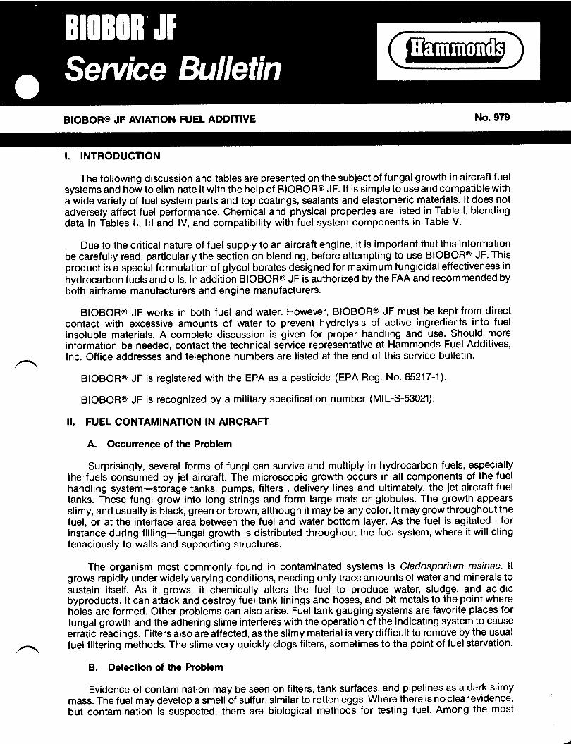
BIOBOR@ JF AVIATION FUEL ADDITIVE No.979
I. INTRODUCTION
The following discussion and tables are presented on the subject of fungal growth in aircraft fuelsystems and how to eliminate it with the help of BIOBOR@ JF. lt is simple to use and compatible witha wide variety of fuel system parts and top coatings, sealants and elastomeric materials. lt does notadversely affect fuel performance. Chemical and physical properties are listed in Table l, blendingdata in Tables ll, lll and lV, and compatibility with fuel system components in Table V.
Due to the critical nature of f uel supply to an aircraft engine, it is important that this informationbe carefully read, particularly the section on blending, before attempting to use BIOBOR@ JF. Thisproduct is a special formulation of glycol borates designed for maximum fungicidaleffectiveness in
hydrocarbon fuels and oils. ln addition BIOBOR@ JF is authorized by the FAA and recommended byboth airframe manufacturers and engine manufacturers.
BIOBOR@ JF works in both fuel and water. However, BIOBOR@ JF must be kept from directcontact with excessive amounts of water to prevent hydrolysis of active ingredients into fuelinsoluble materials. A complete discussion is given for proper handling and use. Should moreinformation be needed, contact the technical service representative at Hammonds Fuel Additives,lnc. Office addresses and telephone numbers are listed at the end of this service bulletin.
BIOBOR@ JF is registered with the EPA as a pesticide (EPA Reg. No. 65217-11.
BIOBOR@ JF is recognized by a military specification number (MIL-S-53021).
!I. FUEL CONTAMINATION IN AIRCRAFT
A. Occurrence of the Problem
Surprisingly, several forms of fungi can survive and multiply in hydrocarbon fuels, especiallythe fuels consumed by jet aircraft. The microscopic growth occurs in all components of the fuelhandling system-storage tanks, pumps, filters , delivery lines and ultimately, the jet aircraft fueltanks. These fungi grow into long strings and form large mats or globules. The growth appearsslimy, and usually is black, green or brown, although it may be any color. lt may grow throughoutthefuel, or at the interface area between the fuel and water bottom layer. As the fuel is agitated-forinstance during filling-fungal growth is distributed throughout the fuel system, where it will clingtenaciously to walls and supporting structures.
The organism most commonly found in contaminated systems is C/adosporium resinae. ltgrows rapidly under widely varying conditions, needing only trace amounts of water and minerals tosustain itself. As it grows, it chemically alters the fuel to produce water, sludge, and acidicbyproducts. lt can attack and destroy fuel tank linings and hoses, and pit metals to the point whereholes are formed. Other problems cin also arise. Fueltank gauging systems are favorite places forfungal growth and the adhering slime interferes with the operation of the indicating system to causeerratic readings. Filters also are affected, as the slimy material is very difficult to remove by the usualfuel filtering methods. The slime very quickly clogs filters, sometimes to the point of fuel starvation.
B. Detection of the Problem
Evidence of contamination may be seen on filters, tank surfaces, and pipelines as a dark slimymass. The fuel may develop a smell of sulfur, similar to rotten eggs. Where there is no clearevidence,but contamination is suspected, there are biological methods for testing fuel. Among the most
convenient of these is the Hum-Bug Detector@ Kit available from Hammonds Fuel Additives, Inc.,Houston, Texas.
Whenever f uel tank areas are opened for a maintenance inspection, a visual examination shouldbe made to determine the presence of slime on interior surfaces and particularly in the sump areawhere slime proliferates. Water, routinely drawn from sump areas, should also be inspected forslimydebris.
Erratic readings from fuel quantity probes may be due to an accumulation of slime deposits.Physical cleaning of the fuel probes may reduce the problem temporarily but regrowth very likelywill occur resulting in faulty readings and further damage because of corrosion.
Positive findings of slime require immediate action to prevent further damage.
C. Prevention of the Problem
The problem of fungicidal contamination in fuels can be alleviated by a two-step procedure:
1. Use of a fungicide, such as BIOBOR@ JF, following the instructions given below.
2. Proper maintenance of the fuel handling system.This is a key step because the effectiveness of even the most efficient fungicide can bereduced if the fuel is allowed to retain fungal debris and high excesses of water. Propermaintenance therefore requires regular removal of accumulated water bottoms anddrainage of sump areas in addition to proper filtering to remove debris. Filters and screensshould be inspected regularly. Storage tanks must be included in regular cleaning andinspection schedules. In some instances, good housekeeping may be all that is needed toprevent fungal growth. However, contamination occurs very easily, and even the bestmaintained system may need the assurance of BIOBOR@ JF.
III. INSTRUCTIONS FOR USE OF BIOBOR@ JF
A. General
Prepare the system before using BIOBOR@ JF by checking the condition of the entire system. lffungal contamination has already occurred there may have been damage that should be repaired. Inbadly contaminated systems, as BIOBOR@ JF kills the microbes, water, chemical and physicaldebris can be released that may further damage or clog the fuel system.
When adding BIOBOR@ JF, consult the dosage charts (Tables ll, lll, and lV), or calculate theamount of BIOBOR@ JF necessary to treat the fuel. For contaminated systems, or tanks prone tofungal attack, use the higher "shock" treatment level. This is calculated at27O ppm BIOBORo JF infuel, or approximately one gallon of BIOBOR@ JF for 5,000 gallons of turbine fuel.
For maintenance in new or previously treated tanks, a level of 135 ppm BIOBOR@ JF or onegallon BIOBOR@ JF in 10,000 gallons of turbine fuel, may be used. Exact usage will vary due tovariations in weather, movement of fuel, and aircraft type. In general, use the lower level as long asthe system is free of fungal growth. lf contamination occurs, use the 270 ppm addition, or treat moreoften, or both. In no instance should BIOBOR@ JF be used at more than 270 ppm in the fuel. Also,consult your aircraft manufacturers'operations manual for recommended frequency of usage.
When using BIOBOR@ JF, check the filters frequently at first. Dying microorganisms willrelease specks of dirt and rust that have been caught in the mats. Also, the slime itself may come offwalls and structures as it is killed. Once dead, the slimy nature of the fungus will disappear, and itshould become more filterable.
Allow sufficient time and surface contact for BIOBOR@ JF to work. Fuel that is treated andimmediately flown off will not result in adequate control. Also, tanks that are not completely filledwith treated fuel may not get protection above the fuel line. BIOBOR@ JF does not vaporize fromstanding fuel, so it will go only where the fuel goes, and will burn off with the fuel. A contact time of36-72 hours is recommended. lf the aircraft must be used. refuel with BIOBOR@ JF treated fuel toachieve the required contact time.
(2)
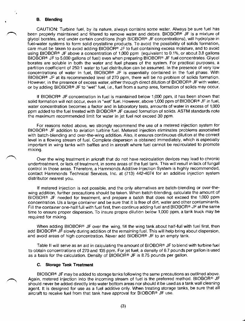
B. Blending
CAUTION: Turbine fuel, by its nature, always contains some water. Always be sure fuel hasbeen properly maintained and filtered to remove water and debris. BIOBOR@ JF is a mixture ofglycol borates, and under certain conditions (high BIOBOR@ JF concentrations), will hydrolyze infuel-water systems to form solid crystalline products. To avoid the possibility of solids formation,care must be taken to avoid adding BIOBOR@ JF to fuel containing excess moisture, and to avoidusing BIOBOR@ JF above a concentration of '1,000 ppm (equivalent to 0.10/0, or about 3.8 gallonsBIOBOR@ JF to 5,000 gallons of fuel) even when preparing BIOBOR@ JF fuelconcentrates. Glycolborates are soluble in both the water and fuel phases of the system, For practical purposes, apaftition coefficient of 250:1 water to fuel distribution can be assumed. In the presence of very lowconcentrations of water in fuel, BIOBOR@ JF is essentially contained in the fuel phase. WithBIOBOR@ JF at its recommended level of 27O ppm, there will be no problem of solids formation.However, in the presence of excess water, either through direct dilution of BIOBORo JF with water,or by adding BIOBOR@ JF to "wet" fuel, i.e., fuel from a sump area, formation of solids may occur.
lf BIOBOR@ JFconcentration in fuel is maintained below 1,000 ppm, it has been shown thatsolid formation will not occur, even in "wet" fuel. However, above 1,000 ppm of BIOBOR@ JF in fuel,water concentration becomes a factor and in laboratory tests, amounts of water in excess of 1,000ppm added to the fuel treated with BIOBOR@ JF caused formation of solids. ASTM standards notethe maximum recommended limit for water in jet fuel not exceed 30 ppm.
For reasons noted above, we strongly recommend the use of a metered injection system forBIOBOR@ JF addition to aviation turbine fuel. Metered injection eliminates problems associatedwith batch-blending and over-the-wing addition. Also, it ensures continuous dilution at the correctlevel in a flowing stream of fuel. Complete dispersion is obtained immediately, which is especiallyimportant in wing tanks with baffles and in aircraft where fuel cannot be recirculated to promotemixing.
Over the wing treatment in aricraft that do not have recirculation devices may lead to chronicundertreatment, or lack of treatment, in some areas of the fuel tank. This will result in lack of fungalcontrol in those areas. Therefore, a Hammonds Additive lnjection System is highly recommended,contact Hammonds Technical Services, Inc. at (713) 4424074 tor an additive injection systemdistributor nearest you.
lf metered injection is not possible, and the only alternatives are batch-blending or over-the-wing addition, further precautions should be taken. When batch-blending, calculate the amount ofBIOBOR@ JF needed for treatment, and prepare a batch that does not exceed the 1,000 ppmconcentration. Us a large container and be sure that it is free of dirt, water and other contaminants.Fill the container one-half full with fuel first, then continue adding fuel and BIOBOR@ JF at the sametime to ensure proper dispersion. To insure propre dilution below 1,000 ppm, a tank truck may berequired for mixing.
When adding BIOBOR@ JF over the wing, fill the wing tank about half{ullwith fuel first, thenadd BIOBOR@ JF slowly during addition of the remaining fuel. This will help bring about dispersion,and avoid areas of high concentration. Never add BIOBOR@ JF to an empty tank.
Table ll will serve as an aid in calculating the amount of BIOBOR@ JF to blend with turbine fuelto obtain concentrations of 270 and 135 ppm. For jet fuel, a density of 6.7 pounds per gallon is usedas a basis for the calculation. Density of BIOBORo JF is 8.75 pounds per gallon.
C. Storage Tank Treatment
BIOBOR@ JF may be added to storage tanks following the same precautions as outlined above.Again, metered injection into the incoming stream of fuel is the preferred method. BIOBOR@ JFshould never be added directly into water bottom areas nor should it be used as a tank wall cleaningagent. lt is designed for use as a fuel additive only. When treating storage tanks, be sure that allaircraft to receive fuel from that tank have approval for BIOBOR@ JF use.
(3)
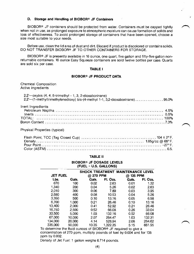
D. Storage and Handling of BIOBOR@ JF Containers
BIOBOR@ JF containers should be protected from water. Containers must be capped tightlywhen not in use, as prolonged exposure to atmospheric moisture can cause formation of solids andloss of effectiveness. To avoid prolonged storage of containers that have been opened, choose asize most suitable to your needs.
Before use, clean the lid area of dust and dirt. Discard if product is discolored or contains solids.DO NOT TRANSFER BIOBOR@ JF TO OTHER CONTAINERS FOR STORAGE.
BIOBOR@ JF is presently available in 16 ounce, one quart, five gallon and fifty{ive gallon non-returnable containers. 16 ounce Easy Squeeze containers are sold twelve bottles per case. Quartsare sold six per case.
TABLE I
BIOBOR@ JF PRODUCT DATA
Chemical CompositionActive Ingredients
2,2'-oxybis (4, 4, 6-trimethyl - 1, 3, 2-dioxaborinane)2,2'-(1-methyltrimethylenedioxy) bis-(4-methyl 1-1,3,2dioxaborinane) ....95.00/o
Inert lngredientsPetroleum Naptha .. 4.5o/oInerts .. 0.50/o
TOTAL: . 1000/oBoron Content ...7.3o/o
Physical Properties (typical)
Flash Point, TCC (Tag Closed Cup) .1O4!2"F.Density ..1.059/cc@68'F.Pour Point ... -27"F.Color (ASTM) . .. 0.5.
TABLE II
BIOBOR@ JF DOSAGE LEVELS(FUEL = U.S. GALLONS)
SHOCK TREATMENT MAINTENANCE LEVELJET FUEL @270PPM @ 135 PPMLbs. Gals. Gals. Fl. Ozs. Gals. Fl. Ozs.670 100 0.02 2.63 0.01 1.32
1,340 200 0.04 5.26 0.O2 2.632,010 300 0.06 7.89 0.03 3.952,680 400 0.08 10.53 0.04 5.263,350 500 0.10 13.16 0.05 6.586,700 1,000 0.21 26.46 0.10 13.16
13,400 2.000 0.41 52.92 0.21 26.4616,750 2.500 0.52 66.08 0.26 33.0433,500 5,000 1.03 132.16 0.52 66.0867,000 10,000 2.07 264.47 1.03 132.31
134,000 20,000 414 528.94 2.06 264.62335,000 50,000 10.35 1,322.35 5.15 661.55
To determine the fluid ounces of BIOBOR@ JF required to give aconcentration of 270 ppm, multiply pounds of fuel by 0.004 and for 135ppm by 0.002.Density of Jet Fuel: 1 gallon weighs 6.714 pounds.
(4)
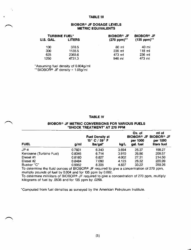
TABLE III
BIOBOR@ JF DOSAGE LEVELSMETRIC EQUIVALENTS
U.S. GAL.
100300625
1250
LITERS
378.51135.52365.64731.3
TURBINE FUEL* BIOBOR@ JF(270 ppm)**
80 ml236 ml473 ml946 ml
BIOBOR@ JF(135 ppm)**
40 ml118 ml236 ml473 ml
.Assuming fuel density of 0.8049/ml".BIOBOR@ JF density = 1.059/ml
TABLE IV
BIOBOR@ JF METRIC CONVERSIONS FOR VARIOUS FUELS"SHOCK TREATMENT" AT 270 ?PI6
FUEL
Fuel Density at150 C/59'F
/ml lbVgal* kg/L
Oz. olBIOBOR@ JF
per 1000gal. fuel
ml ofBIOBOR@ JF
per 1000literc fuel
JP-4Kerosene (Turbine Fuel)Diesel #1
Diesel #2Bunkgr "C"
0.7601 6.3430.8045 6.7140.8180 6.827
3.694 25.373.910 26.864.002 27.314.123 28.324.837 33.22
0.84840.9952
7.0808.305
198.27209.57214.50220.99259.26
To determine the fluid ounces of BIOBOR@ JF required to give a concentration of 27O ppm,multiply pounds of fuel by 0.004 and for 135 ppm by 0.002.To determine milliliters of BIOBOR@ JF required to give a concentration of 270 ppm, multiplykilograms of fuel by .0536 and for 135 ppm by .0268.
.Computed from fuel densities as surveyed by the American Petroleum lnstitute.
(5)
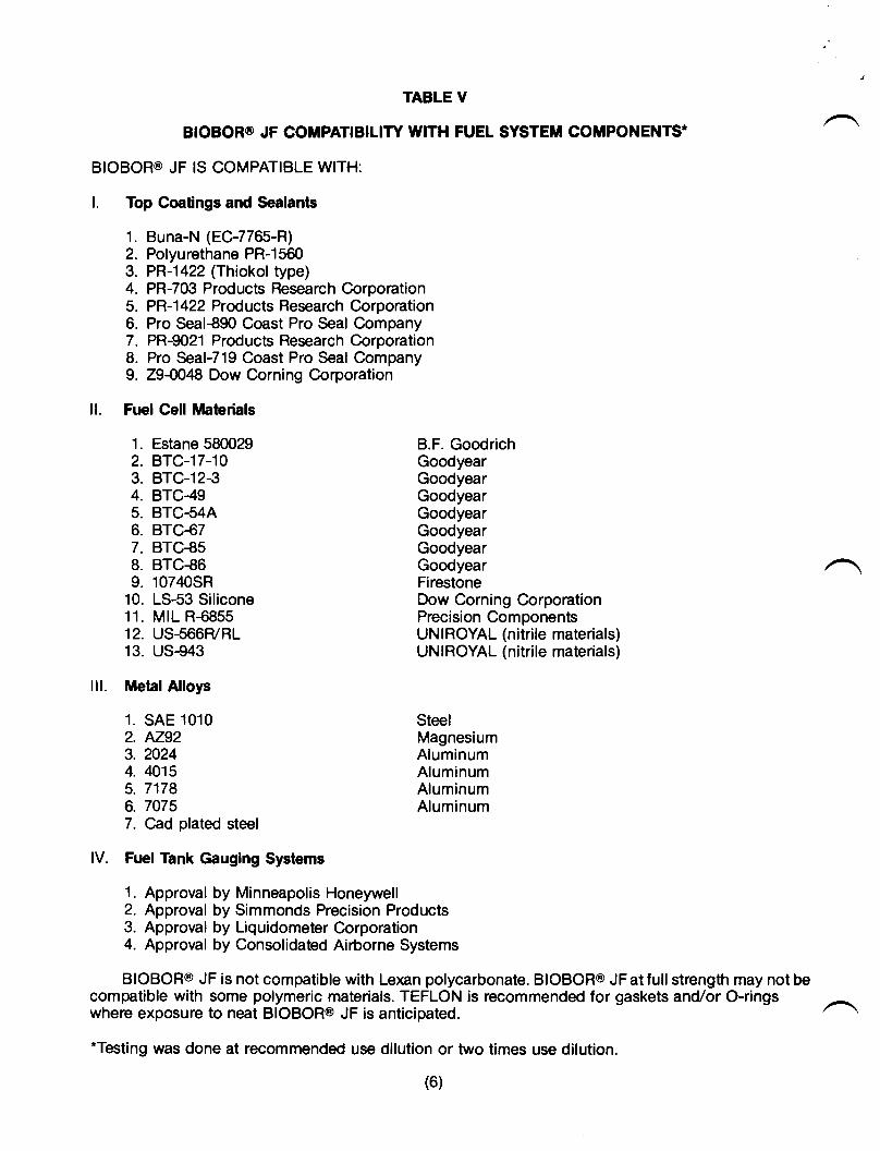
TABLE V
BIOBOR@ JF COMPATIBILITY WITH FUEL SYSTEM COMPONENTS*
BIOBOR@ JF IS COMPATIBLE WITH:
l. Top Coatings and Sealants
1. Buna-N (EC-7765-R)2. Polyurethane PR-15603. PR-1422 (Thiokol type)4. PR-703 Products Research Corporation5. PR-1422 Products Research Corporation6. Pro Seal€90 Coast Pro Seal Company7. PR-9021 Products Research Corporation8. Pro Seal-719 Goast Pro Seal Company9. 29{048 Dow Corning Corporation
ll. Fuel Cell Mabrials
1. Estane 580029 B.F. Goodrich2. BTC-17-10 Goodyear3. BTC-12€ Goodyear4. BTC-49 Goodyear5. BTC-54A Goodyear6. BTC€7 Goodyear7. BTC€S Goodyear8. BTC€6 Goodyear9. 10740SR Firestone
10. LS-53 Silicone Dow Corning Corporation11. MIL R-6855 Precision Components12. US-566F/RL UNIROYAL (nitrile materials)13. US-943 UNIROYAL (nitrile materials)
lll. Metal Alloys
1. SAE 1010 Steel2. AZ92 Magnesium3.2024 Aluminum4. 4015 Aluminum5. 7178 Aluminum6. 7075 Aluminum7. Cad plated steel
lV. Fuel Tank Gauging Systems
1. Approval by Minneapolis Honeywell2. Approval by Simmonds Precision Products3. Approval by Liquidometer Corporation4. Approval by Consolidated Airborne Systems
BIOBOR@ JF is not compatible with Lexan polycarbonate. BIOBOR@ JFatfullstrength may not becompatible with some polymeric materials. TEFLON is recommended for gaskets and/or O-ringswheie exposure to neai BiOBOR@ JF is anticipated.
*Testing was done at recommended use dilution or two times use dilution.
(6)
COMPANIES WHICH RECOMMEND THE USE OF BIOBOR@ JF
AIRCRAFT MANUFACTURERS ENGINE ACCESSORIES AND FUELMONITORING EQUIPMENT
Gulfstream Aerospace Corp. MANUFACTURERSBoeing AircraftBeechcraft Aircraft Corp.Dassault Falcon Jet Dahl Filter CorporationBell Helicooter Velcon Filters, Inc.Fokker Aircraft Corp. Stanadyne Filter/Fuel InjectionLearJet Corporation SystemsLockheed Aircraft Company Airborne Fuel FiltersSikorsky Helicopter Consolidated Airborne Systemslsrael Aircraft Industry Ltd. Liquidometer CorporationHughes Helicopter Minneapolis HoneywellBritish Aerospace Aircraft Simmonds Precision ProductsMcDonnell Douglas Aircraft Facet Filter CorporationSaberliner Aircraft Corp.
AIRCRAFT ENGINE MANUFACTURERS FUEL SERVICE COMPANIES
Rolls Royce Engines Paulsen IndustriesLycoming Engine Corporation National Biocide ServicesPratt & Whitney Engines |.C.E.S., Inc.Allison IndustriesGarrett Aircraft EnginesGeneral Electric Engines DivisionAllied Signal Aerospace Corp.
DIESEL ENGINE MANUFACTURERS TANK MANUFACTURERS
Detroit Diesel Corp. Uniroyal Tank and PlasticCaterpillar Tractor Corp. Production DivisionIntenational Harvester Tractor Co. Goodyear AerospaceWaukesha/Dresser Engines U.S. Steel TankCummins Engine Co., lnc. Firestone Tank DivisionGeneral Motors - Diesel Engine Division Dow Corning TanksMercedes Benz A.O. Smith FiberglassJohn Deere Tractor Tank CorP.
BF Goodrich Aerospace
The OEM's listed above suggest the use of BIOBOR@ JF as part of their standard maintenanceprograms. This endorsemeni appears in the Equipment Maintenance Manuals under Engine'Airlrame or Fuel System Care.
(7)
HAMMONDS FUEL ADDITIVES, INC.P.O. BOX 3811+407 o HOUSTON, TEXAS 7723&8114
(713) 442-3777 o FAX: (713) 442-3974
NOTICE: THERE ARE NO WARRANTIES, EXPRESS OR IMPLIED INCLUDING ANYWARRANTY OF FITNESS FOR A PARTICULAR PURPOSE, WHICH EXTEND BEYOND THEDESCRIBED USES IN THIS BULLETIN.
WARNING: ON ALL PRODUCTS, AVOID PROLONGED INHALAT]ON OR PROLONGED SKINCONTACT. NOT FOR FOOD OR DRUG USE. READ ALL INSTRUCT]ONS RELATING TOTHE PRODUCTS BEFORE USE.
lf possible uses of these products have been mentioned herein, it is not intended that theabove products be used to practice any applicable patent, whether mentioned in this Bulletinor not, without procurement of a license, if necessary, from the owner, following investigationby the user.
e1992. All Rights Reserved.
(8)
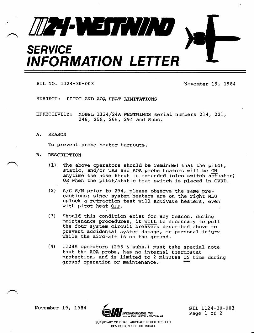
TWTSERY'CEINFORMATION LETTER
A.
B.
srl, No. 1124-30-003
SUBJECT: PITOT AllD AOA HEAT LIMITATIONS
November L9, 1984
EFFECTIVITY: MOEEL IL24/24A WESTWINDS serial numbers 2L4, 22Ll246, 258, 266, 294 and Subs.
REASON
To prevent probe heater burnouts.
DESCRIPTION
(1) The above operators should be reminded that the pitot,static, and/or TAS and AOA probe heaters will be ONanytime the nose ttrut is extended (oleo switch a&uator)OR when the pitotr/static heat switch is placed in OVRD.
(2) A/C S/N prior to 294r. please observe the same pre-cautions; since system heaters are on the right MLGuplock a retraction test will activate heaters, evenwith pitot heat OFF.
(3) Should this condition exist for any reason, duringmaintenance procedures, it WILL be necessary to pullthe four system circuit breffis described lbove toprevent accidental system damage r ot personal injurywhile the aircraft is on the ground.
(4) 1124A operators (295 c subs.) must take special notethat the AOA probe, has no internaL thermostatprotection, and is limited Lo 2 minutes ON time duringground operation or maintenance. :
srl, 1124-30-003Page I of 2
SUBSIDIARY OF ISRAEL AIRCRAFT INDUSTRIES, LTD
BEN GURION AIRPORT. ISRAEL
/@ lill s;rmsp*t* !,!#;., *,,*
November 19, 1984
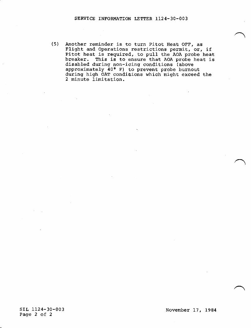
SERVICE INFORMATION LETTER 1124-30-OO3
(5) Another reminder is to turn Pitot Heat, OFF, asFlight and Operations restrictions permitr or, ifPitot heat is required, to pull the AOA probe heatbreaker. This is to ensure that AOA probe heat isdisabled during non-icing conditions (aboveapproximately 40o F) to prevent probe burnoutduring high OAT conditions which might exceed the2 minute limitation.
srl, 1124-30-003Page 2 of 2
November L7, 1984
twtSERY'CEINFORMATION LETTER
SERVICE INFOR]T,IATION LETTER NO. 1 124-30-080 May 29, L990
SUBJECT: ICE AND RAIN PROTECTION - ENGINE IIP BLEEDI4ANIFOLD ASSEMBLY
MODEL LIZ'ILIZ,AWESTWIND, all serial numbers.EFT'ECTTVITY:
A. REASON
Joinform operators of the availability of a new bleed manifotd assembly, PA.{FL0ASP20242-9.
B. REFERENCE
None.
C. PUBLICATIONSAIIFECTED
112+l LTz4[Westwind Illustrated parts catalog, chapter 3G20-00.
D. DESCRIPTION
Due to field reports of a high failure rate of the F10A5nv24z-7 bleedmanifold assemblS a new manifold, P/N F10A5%U2A2-9 has been designedwhich has a reinforcement saddle welded in the area where the engine anti-iceline attaches. Undamaged and cracked -7 manifold assemblies *ayb"exchanged through Atlantic Supply Company for the -9 configuration if thedamage limitations set forth by the manufacturer are not exceeded. Broken -7manifold assemblies are not exchangeable.
May 29, L990906
srLtr24-30-080Page 1of 1
I-tI
f!
SERVICE LETTERSUBJECT TIMKEN PERFORMANCE CODE 629 FOR BEARING CUPS AND BEARING CONES
SECT]ON I- PLANNING INFORMATION
A. EFFECTIVITY: This Service Letter is applicable to all Aircraft Braking Systems Corporation(ABSC) Wheel Assemblies.
B. REASON: The Timken Gompany identifies certain bearing cups and bearing cones used on
ABSC wheel assemblies with Performance Code 629.
C. DESCRIPTION: This Service Letter is issued to tell operators what the Timken PerformanceCode 629 is and how to identify bearing cups and bearing cones that were made to the TimkenPerformance Code 629 specification. This Service Letter also tells operators which ABSC wheel
assemblies must use the Timken Performance Code 629 bearing cups and bearing cones. This
Service Letter supersedes General Service Letter GS-SL-9.
D. APPROVAL: This Service Letter contains no modification information that revises the approvedconfiguration and therefore does not require government or other regulatory agency approval.
E. WEIGHT AND BALANCE: None.
F. REFERENCE:
(1) All Component Maintenance Manuals and Overhaul Manuals for Aircraft Braking SystemsCorporation Wheel Assemblies used on Commerdd, Military and General Utility Aircraft.
(2) General Service Letter GS-SL-9 (basic issue dated Feb 9/83) for Aircraft Wheel BearingGlass Numbers.
SECTION II - ACCOMPLISHMENT INSTRUCTIONS
A. Timken Performance Code 629:
A Performance Code as told by the Timken Company is "a set of manufacturing instructions thatdifferentiate a component from standard product in order to meet specific requirements of the cus-tomer." The differences between the standard bearing cups and bearing cones and those bearingcups and bearing cones identified by Timken Performance Code 629 are:
(1) Cup races, cone races and roller bodies are honed to improve contiact surface finish.
(2) Cups and cones are 100% examined for correct hardness.
(3) Specialquality control measures are done when the bearing cups and bearing cones aremade.
(4) Bearing cups and bearing cones that are approved by Timken Performance Code 629 areidentified as "2-629" or "4429" adjacent to the part number. The lirst digit is the bearingclass (2 or 4) and the last three digits indicate the performance code.
B. ABSC lets Timken Performance Code 629 bearing cups and bearing cones be used on allABSGwheel assemblies. Refer to Figure 1 for the Timken Performance Code 629 approved bearings.
However, the installation of Timken Performance Code 629 bearing cups and bearing cones is
mandatory in all of the ABSC wheel assemblies shown in Figure 2and in all ABSC wheel assem-
blies wheie the Component Maintenance Manual or Overhaul Manual has specified that Timken
Performance Code 629 components must be used.
Feb 18/94
(RELEASuI,AfuiGS-SL-38Page 1 of3
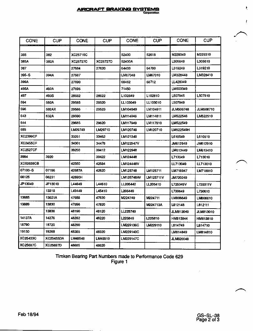
CONE CUP CONE CUP CONE CUP CONE CUP
385 982 xc257t0c 524m 52618 M229349 M229310
385A 3824 xc25727C xc25727D 524004 1305649 1305610
387 276€,4 276?0 64433 4f700 1319249 1319210
395-S 394A 276€7 1M67048 1M67010 1M328448 1111328410
3994 27690 68462 6a712 11428349
495A 4924 27695 714fi 1Ms03349
497 493S 28682 28622 1102849 1102810 1507945 1507910
594 5924 29585 295?0 11103049 11103010 1507949
596 5924X 29586 29523 1M104949 1M104911 J1M508748 JLld5@710
643 632A 29s90 1M114848 1M114811 1M522546 LM522510
644 29685 29620 1M117949 1M117910 1M522549
685 lM29749 1M29710 1Ml20749 1M120710 1M522549H
xc2399CF 3{t251 33/,62 1M121349 1610549 1610510
xc24sscF 34301 s4/78 LM12847V JM612949 Jlr/F12910
xc2527CF 39250 39412 1M1229'18 1M613449 1tt 613410
3984 3920 stA22 LMI24/.48 17130t9 1713010
xc02638CB 42350 425U 1M124448V 11713049 11713010
07100-s 07196 426€74 42f2o 1M125748 Llr1257't1 LM7189/.7 1M718910
08125 08231 42690H 1Ml25748AV 1M125711V JM7?p249
JP13049 JP13010 144649 144610 LL206442 11205410 1725349V 1725311V
19t18 145449 L4At10 L205449 1730649 1730610
13685 136214 47688 476?0 M224749 in24711 1M806649 Li/406610
13889 13830 47896 47820 iIQ2471SA 1812148 1812111
13836 48190 48120 LL2?5749 JLM813049 JLlt81S010
141S74 14276 4€,282 482?0 1225849 1225810 HM813844 HM813810
18790 18720 48290 1M229136C 1f,1229110 1a14749 L814710
19150 19268 48385 48320 1M2291loc 1M814849 1tt1814810
xc25433C XC25rt33DA LM485lA 1ii48510 LM229147C JLM82@'18
xc25697C xc25697D'|8685 48620
Timken Bearing Part Numbers made to Performance Code 629Figure 1
Feb 18/94 GS-SL-38Page 2 of 3
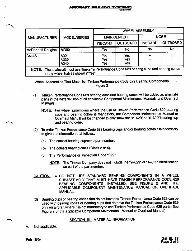
Wheel Assemblies That Must Use Timken Performance Code 629 Bearing ComponentsFigure 2
(1) Timken Performance Code 629 bearing cups and bearing cones willbe added as alternateparts in the next revision of allapplicable Component Maintenance Manuals and OverhaulManuals.
NOTE: For wheel assemblies where the use of Timken Performance Code 629 bearingcups and bearing cones is mandatory, the Component Maintenance Manual orOverhaul Manual will be changed to only show the "2429" or "4429" bearing cupand bearing cone.
(21 To order Timken Performance Code 629 bearing cups and/or bearing cones it is necessaryto give the information that follows:
(a) The conect bearing cup/cone part number.
(b) The conect bearing class (Class 2 or 4).
(c) The Performance or Inspection Code "629".
NOTE: The Timken Company does not include the "2-€29" or "4429" identificationets part of the part number.
CAUTION: o DO NOT USE STANDARD BEARING COMPONENTS lN A WHEELSUBASSEMBLY THAT MUST HAVE TIMKEN PERFORMANCE CODE 629BEARING COMPONENTS INSTALLED. SEE FIGURE 2 AND THEAPPLICABLE COMPONENT MAINTENANCE MANUAL OR OVERHAULMANUAL.
(3) Bearing cups or bearing cones that do not have the Timken Performance Code 629 can be
used witn bearing cones or bearing cups that do have the Timken Performance Code 629
only on aircraft where it is not mandatory to use Timken Performance Code 629 parts (See
Figure 2 or the applicable Component Maintenance Manual or Overhaul Manual).
SECTION III- MATERIAL INFORMATION
A. Not applicable.
MANUFACTURER MODEUSERIES
WHEEL ASSEMBLY
MAlN/CENTER NOSE
INBOARD OUTBOARD INBOARD OUTBOARD
McDonnell Douglas MD9O Yes No No No
SNIAS 4321A330A340
YesYesYes
YesYesYes
NOTE: These aircraft must use Timken's Performance Code 629 bearing cups and bearing conesin the wheel halves shown ("Yes").
Feb 18/94 GS-SL-38Page 3 of 3
TW{SERY'CEINFORMATION LETTER
SERVICE INFORMATION LETIM, NO. 1124-32-IOO September l,1993
SUBJECT: LANDING GEAR - WHEEL INSPECTION AND OVERHAI]LSCHEDULES
EFFECTIVITY: MODEL 112411124A WEST'WIND, all serial numbers.
A. REASON
To provide information regarding Aircraft Braking Systems guidelines for wheelinspection and overhaul.
B. REFERENCE
ABSC General Service Letter GS-SL-36.
C. PUBLICATIONS AFFECTED
None
D. DESCRIPTION
Aircraft Braking Systems Corporation has issued General Service LetterGS-SL-36 which discusses guidelines which may be applied by operators ofaircraft equrpped with ABSC wheel assemblies.
This General Service Letter is issued to give operators guidelines for inspection
and overhaul increments. It is not mandatory for operators to use the overhaulincrements given in this Service l-etter. Experienced operators can better predictthe overhaul increments and determine procedures to be done at each overhaul.This Service Letter also gives a guide for a start-up maintenance program.
For a copy of ABSC General Service Letter GS-SL-36, contact:
Aircraft Braking Systems Corp.Publication s Department1204 Massillon RoadAkron, OH 44306
September 1, 1993s266
216-796-8081 - Office216-796-9805 - Fax
str. 1124-32-lWPage 1 of 1
F.
{III{,
GS-SL-36Page 1 of 7
SERVICE LETTERSUBJECT: WHEEL INSPECTION AND OVERHAUL SCHEDULES
SECTION I_ PLANNING INFORMATION
A. EFFECTIVITY: This General Service Letter is applicable to allAircraft Braking Systems Corpora-tion wheel assemblies used on various aircraft.
B. REASON: The increment between overhauls varies greatly for each wheel assembly. Experi-enced operators know the operation of their equipment and the inspection results. Where suchexperience is not available, it is necessary tor operators to have guidelines to determine whennormal overhaul procedures must be done on a wheel assembly.
C. DESCRIPTION: This General Service Letter is issued to give operators guidelines for inspectionand overhaul increments. lt is not mandatory for operators to use the overhaul increments givenin this Service Letter. Experienced operators can better predict the overhaul increments and de-cide what procedures should be done at each overhaul. This Service Letter gives a guide for astart-up maintenance prog ram.
NOTICE
ATRCRAFT BRAKTNG SYSTEMS CORPORATTON (ABSC.)ASSUMES NO CON-TRACTUAL, WARRANTY PRODUCT LIABILITY OR OTHER OBLIGATION FORANY SUBSTITUTION OF OR ALTERATION TO ANY PART CONTAINED IN ANYABSC WHEEL OR BRAKE ASSEMBLY INCLUDING ACCESSORIES NOT SPE-CIFICALLY AUTHORIZED BY ABSC OR FOR ANY ALTERATION NOT PER-FORMED IN ACCORDANCE WITH ABSC APPROVED PROCEDURES.
D. APPROVAL: This General Service Letter contains no modification information that revises theapproved configuration and therefore does not require government or other regulatory agencyapproval.
E. WEIGHT AND BAI-ANCE: None.
F. REFERENCE: All Aircraft Braking Systems Corporation Overhaul and Component Mainte-nance Manuals for allwheel assemblies.
SECTION II _ ACCOMPLISHMENT INSTRUCTIONS
A. GENERALINFORMATION:
(1) Aircraft Braking Systems Corporation (ABSC) aircraft wheel assemblies are manufacturedto the highest quality standards.
(a) As with all aircraft components, the probabili$ of fatigue failure for a wheel assemblyincreases as the service time of awheel assembly increases. ln addition, too much tirepressure, poor landing conditions, runway obstacle impacts, corrosion, surface dam-age, and incorrect wheel maintenance can decrease the service life of the wheel as-sembly. lt is for these reasons that the length of inspection and overhaul incrementsdecreases as the wheel service time increases.
(b) ABSC wheel assemblies are designed to give a long and reliable service life when cor-rectly maintained as told in the appropriate Component Maintenance Manual (CMM).
(c) The CMM's give all the necessary inspection and repair procedures for normal mainte-nance of wheelassemblies. The CMM's do notgive aspecific incrementforwhen theseprocedures must be done.
. ABSC is the registered trademarkffingrafJ Braking Systems Corporation
Jul 1e/e3 (RELEAsEDOIfu&)
l- Many airlines have asked for specific inspectionioverhaul increments, but the AirTransportation Association (ATA), Specif ication 1 00, states :
Time limits (including shelf life components) for scheduled inspections or checksin the procedures are specifically prohibited unless required bygovernment regu-lation. Airlines do desire manufacturer's recommendations, but if provided t6eymust be in a separate document.
Z lt is the purpose of this Service Letter to give ABSC's recommendations on in-spection/overhaul increments.
(21 Wheel Inspection and Overhaul procedures:
(a) The ultrasonic and eddy current inspection procedures given in the CMM's have a reli-ability of 95 percent and 90 percent respectively. The reliability factor of these methodshas a relation with the knowledge, accuracy and experience of the operator.
(b) This Service Letter gives the wheel inspection and overhaul procedures that must bedone at each maintenance increment to make sure the wheel assembly is correcflymaintained. The maintenance increments are calculated to optimize the wheel servicelife and economic factors.
B. INSPECTIONFREQUENCIES:
(1) As told in all ABSC Component Maintenance Manuals, each operator must schedule main-tenance based on the condition of his equipment. ABSC recommends that on-conditionmaintenance be performed.
(a) The World Airlines Technical Operations Glossary WATOG) defines on-conditionmaintenance as follows:
A primary maintenance process having repetitive inspections ortests to determine thecondition of units, systems or portions of structure with regard to continued serviceabili-ty (conective action is taken when required by item condition).
(2) ABSC cannot accurately create a "formula" to predict wheel retirements or recommend in-crements for wheel inspections and overhaul because of the variables that follow:
(a) The amount of scatter in the frequency of wheel retirements between operators.
(b) Repairs done to the wheel assembly and upgrades to the wheel assembly also changethe length of the wheel service life.
(c) The operation environment and the maintenance practices, which have a direct rela-tionship with wheel service life, differ for each operator.
(3) Operators who know more about the wheel's service life history can create their own inspec-tion and overhaul schedules.
(4) For other operators, ABSC recommends the operators use the information given in this Ser-vice Letter to make wheel inspection and overhaul schedules.
NOTE: On-condition maintenance remains the primary recommendation of ABSC.
GS-SL-36Page 2 of 7
Jul 19/93
(5) ABSC recommends that operators use the comments given below when they make inspec-
tion and overhaul schedules for their wheel assemblies:
(a) lt is recommended that operators with established inspection and overhaul schedulescontinue to use their inspection schedules.
(b) The guidelines given in this Service Letter are intended to help operators make theirown inspection and overhaulschedules. These guidelines must be changed to corre-spond to the actual service history of a particular wheel assembly.
(c) Aircraftwheels are highly stressed components that are sensitive to handling damageand maintenance procedures. Aircraftwheels have afinite lifewhich can be maximizedby careful handling. Operators must do only the maintenance procedures given theCMM in order to maximize the service life of the wheel.
(d) lt is recommended that an eddy current inspection of the bead seat area of allwheelassemblies be made at each tire change if the eddy current inspection equipment isavailable. Otherwise, an eddy current inspection or ultrasonic inspection of the wheelhalves must be made at each overhaul.
(e) When wheel halves with different amounts of wear are used in the same wheel assem-bly, the inspection schedule for the most worn wheel half must be used.
(f) lf the service history of the wheel assembly (or one of the wheel halves) is not known,the wheel assembly must be overhauled at each tire change.
(g) Maintenance records must be kept for each wheel subassembly to make the mainte-nance schedules effective. This will make sure that the maintenance of the wheelhalves is not lost. lnclude the information that follows in the maintenance record: re-pairs done to the wheel half, totalaccumulated mileage, the total number of landingsand the number of tire changes.
(h) Aircraft Braking Systems Corporation assumes no responsibility for wheel failurescaused by poor/incorrect or infrequent overhaul procedures that result in property loss/damage and/or personal injury.
OVERHAUL PROCEDURES:
(1) The Component Maintenance Manual is written to give step by step procedures to overhaulthe wheel assembly. The CMM is divided into sections which include: TESTING AND FAULTISOLATION, DISASSEMBLY CLEANING, CHECK, REPAIR and ASSEMBLY AND STOR-AGE. These sections must be followed in the order given in the CMM to correctly overhaulthe wheel assembly. The CMM also includes sections with information on the wheel assem-bly and the equipment needed to assemble the wheel. These sections include: DESCRIP-TION AND OPERATION, FITS AND CLEARANCES, SPECIAL TOOLS, FIXTURES ANDEQUIPMENT ANd ILLUSTRATED PARTS LIST.
GS-SL_36Page 3 of 7
c.
Jul 19/93
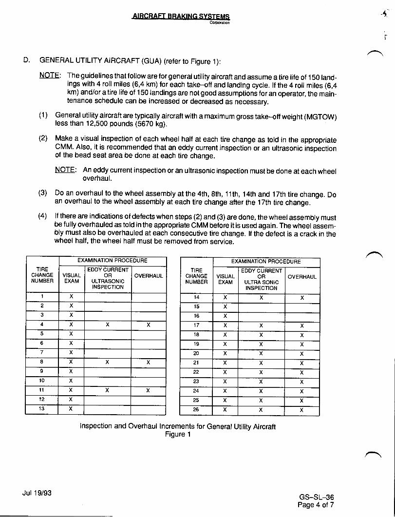
D. GENERAL UTIL|TY ATRCRAFT (cUA) (refer to Figure 1):
NOTE: The guidelines that follow are for general utility aircraft and assume a tire life of 150 land-ings with 4 roll miles (6,4 km) for each take<ff and landing cycle. lf the 4 roll miles (6,4km) and/or a tire life of 150 landings are not good assumptions for an operator, the main-tenance schedule can be increased or decreased as necessary.
(1) General utility_aircraft are typically aircraftwith a maximum gross take-off weight (MGTOW)less than 12,500 pounds (5670 kg).
(2) Make a visual inspection of each wheel half at each tire change as told in the appropriateCMM. Also, it is recommended that an eddy current inspection or an ultrasonic inspectionof the bead seat area be done at each tire change.
NOTE: An eddy current inspection or an ultrasonic inspection must be done at each wheeloverhaul.
(3) Do an overhaul to the wheel assembly at the 4th, 8th, 11th, 14th and 1 7th tire change. Doan overhaul to the wheel assembly at each tire change after the 17th tire change.
(4) lf there are indications of defects when steps (2) and (3) are done, the wheel assembly mustbe fully overhauled as told in the appropriate CMM before it is used again. The wheel assem-bly must also be overhauled at each consecutive tire change. lf the defect is a crack in thewheel half, the wheel half must be removed from service.
,+
TIRECHANGENUMBER
EMMINATION PROCEDURE
VISUALEXAM
EDDY CURRENTOR
ULTRASONICINSPECTION
OVERHAUL
I X
2 X
3 X
4 X X X
5 X
5 X
X
I X X X
9 X
10 X
11 X X X
12 X
't3 X
TIRECHANGENUMBER
EXAMINATION PROCEDURE
VISUALExAM
EDDY CURRENTOR
ULTRA SONICINSPECTION
OVERHAUL
14 X X X
15 X
16 X
17 X X X
18 X X X
19 X X X
20 X X X
21 X X X
22 X X X
23 X X X
24 X X X
25 X X X
26 X X X
Inspection and Overhaul Increments for General Utility AircraftFigure 1
GS_SL-36Page 4 ot 7
Jul 19/93
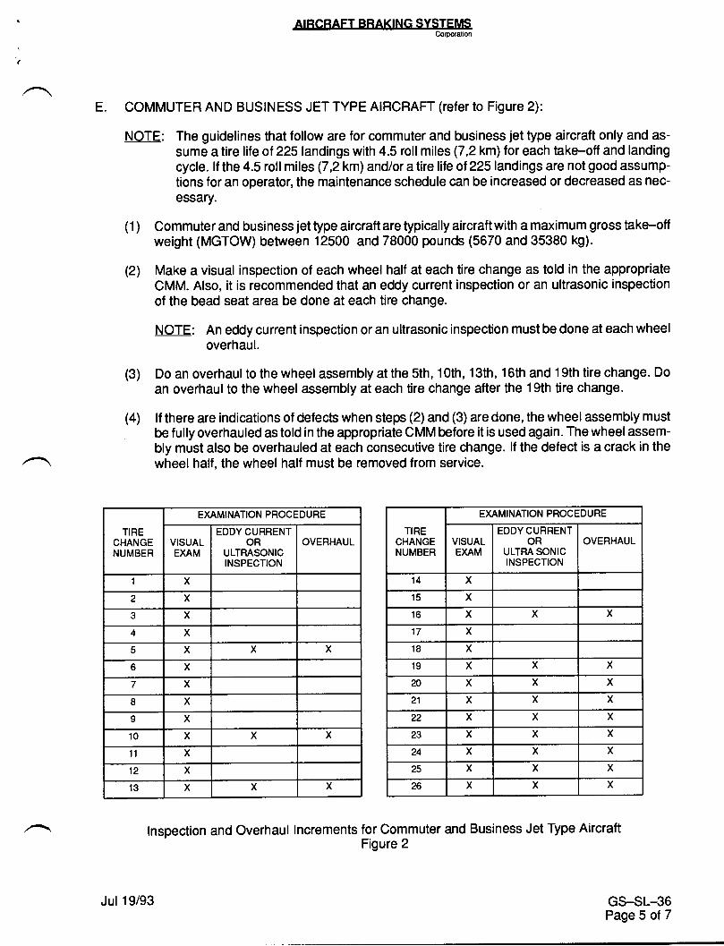
ATRCRAFT BRAKTNG SY$TEMS
E. COMMUTER AND BUSINESS JET TYPE AIRCRAFT (refer to Figure 2):
NOTE: The guidelines that follow are for commuter and business jet type aircraft only and as-sume a tire life of 225landings with 4.5 roll miles (7,2km) for each take-off and landingcycle. lf the4.5rollmiles (7,2km)and/oratirelife ot225landingsarenotgoodassump-tions for an operator, the maintenance schedule can be increased or decreased as nec-essary.
(1) Commuter and business jet type aircraft are typically aircraftwith a maximum gross take-offweight (MGTOW) between 12500 and 78000 pounds (5670 and 35380 kg).
(21 Make a visual inspection of each wheel half at each tire change as told in the appropriateCMM. Also, it is recommended that an eddy current inspection or an ultrasonic inspectionof the bead seat area be done at each tire change.
NOTE: An eddy current inspection or an ultrasonic inspection must be done at each wheeloverhaul.
(3) Do an overhaul to the wheel assembly at the sth, 1Oth, 13th, 16th and 19th tire change. Doan overhaul to the wheel assembly at each tire change after the 19th tire change.
(4) lf there are indications of defects when steps (2) and (3) are done, the wheel assembly mustbe fully overhauled as told in the appropriate CMM before it is used again. The wheel assem-bly must also be overhauled at each consecutive tire change. lf the defect is a crack in thewheel half, the wheel half must be removed from service.
TIRECHANGENUMBER
EXAMINATION PROCEDURE
VISUALEXAM
EDDY CURRENTOR
ULTMSONICINSPECTION
OVERHAUL
1 X
2 X
X
X
X X X
o X
7 X
8 x
9 X
10 X X X
11 X
12 x13 X X X
TIRECHANGENUMBER
EXAMINATION PROCEDURE
VISUALEXAM
EDDY CURRENTOR
ULTRASONICINSPECTION
OVERHAUL
14 X
15 X
16 X X X
17 X
18 X
,to X X X
20 X X x21 X X X
22 X X X
23 X X X
24 X X X
25 X X X
26 X X X
Inspection and Overhaul Increments for Commuter and Business Jet Type AircraftFigure 2
GS-SL_36Page 5 of 7
Jul 19/93
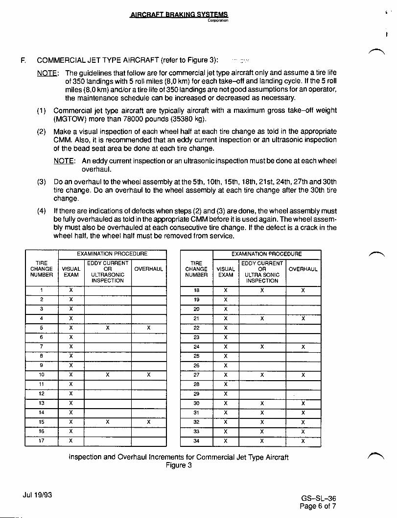
COMMERCIAL JET TYPE AIRCRAFT (refer to Figure 3): :.'!
NOTE: The guidelines that follow are for commercialjet type aircraft only and assume a tire lifeof 350 landings with 5 roll miles (8,0 km) for each take+ff and landing cycle. lf the 5 rollmiles (8,0 km) and/or a tire life of 350 landings are not good assumptions for an operator,the maintenance schedule can be increased or decreased as necessary.
(1) Commercial jet type aircraft are typically aircraft with a maximum gross take<ff weight(MGTOW) more than 78000 pounds (35380 kg).
(2) Make a visual inspection of each wheel half at each tire change as told in the appropriateCMM. Also, it is recommended that an eddy current inspection or an ultrasonic inspectionof the bead seat area be done at each tire change.
NOTE: An eddy current inspection or an ultrasonic inspection must be done at each wheeloverhaul.
(3) Do an overhaul to the wheel assembly at the sth, 1Oth, 1sth, 18th, 21st, 24th, 27th and 30thtire change. Do an overhaul to the wheel assembly at each tire change after the 30th tirechange.
(4) lf there are indications of defects when steps (2) and (3) are done, the wheel assembly mustbe fully overhauled as told in the appropriate CMM before it is used again. The wheel assem-bly must also be overhauled at each consecutive tire change. lf the defect is a crack in thewheel half, the wheel half must be removed from service.
TIRECHANGENUMBER
EXAMINATION PROCEDURE
VISUALEXAM
EDDY CURRENTOR
ULTRASONICINSPECTION
OVERHAUL
I X
2 X
.t X
4 X
c X X X
5 X
7 X
8 X
9 X
10 X X X
ll X
12 X
3 X
4 X
5 X X X
o X
X
TIRECHANGENUMBER
EXAMINATION PROCEDURE
VISUALEXAM
EDDY CURRENTOR
ULTMSONICINSPECTION
OVERHAUL
18 X X X
19 X
N X
21 X X X
22 X
23 X
24 X X X
25 X
26 X
27 X X X
28 X
29 X
30 x X X
31 X X X
32 X X X
33 X X xu X X X
Inspection and Overhaul lncrements for Commercial Jet Type AircraftFigure 3
GS-SL-36Page 6 of 7
Jul 19/93
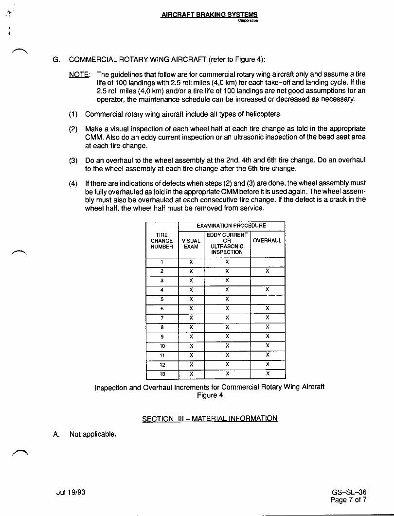
G. COMMERCIAL ROTARY WING AIRCRAFT (refer to Figure 4):
NOTE: The guidelines that follow are for commercial rotary wing aircraft only and assume a tirelife of 100 landings with 2.5 roll miles (4,0 km) for each take-off and landing cycle. lf the2.5 roll miles (4,0 km) and/or a tire life of 100 landings are not good assumptions for anoperator, the maintenance schedule can be increased or decreased as necessary.
(1) Commercial rotary wing aircraft include all types of helicopters.
(2) Make a visual inspection of each wheel half at each tire change as told in the appropriateCMM. Also do an eddy current inspection or an ultrasonic inspection of the bead seat areaat each tire change.
(3) Do an overhaul to the wheel assembly at the 2nd, 4th and 6th tire change. Do an overhaulto the wheel assembly at each tire change after the 6th tire change.
(4) lf there are indications of defects when steps (2) and (3) are done, the wheel assembly mustbe fully overhauled as told in the appropriate CMM before it is used again. The wheel assem-bly must also be overhauled at each consecutive tire change. lf the defect is a crack in thewheel half, the wheel half must be removed from service.
TIRECHANGENUMBER
EXAMINATION PROCEDURE
VISUALEXAM
EDDY CURRENTOR
ULTMSONICINSPECTION
OVERHAUL
'I x X
2 X X X
J X X
4 x X X
5 X xt X X X
X X X
I X X X
9 x X X
10 X X X
11 X X X
12 X X X
13 X X X
lnspection and Overhaul lncrements for Commercial Rotary Wing AircraftFigure 4
A. Not applicable.
GS_SL-36PageT ot7
Jul 19/93
SECTION III _ MATERIAL INFORMATION
tilE{SERY'CEINFORMATION LETTER
srl, No. LL24-32-022 March 20, 1985
SUBJECT: STEERING YOKE - GREASE FITTING REPLACEMENT
EFFECTIVITY: MODEL LL24/24A WESTWIND aircraft, serial numbers354-359, 351 and subsequent.
A. REASON
To eliminate interference between the steering yoke greasefitting and the upper body (Sgo steering onlyl.-
B. REFERENCES
Ll24/24A Illustrated Parts Catalog Chapter 32-50-00,Figure 7t Item 31.
C. PUBLICATIONS AFFECTED
LI24/1124A lllustrated Parts Catalog Chapter 32-50-00 willbe revised to reflect the modification described.
D DESCRTPTION
Several aircraft equipped with 58o steering have experienceddamage to the grease fitting installed in the aft side ofthe P/N 8512971-501 yoke because of interference withthe upper body.
This problem can be corrected by replacing the MS15001-1grease fitting with p,/N 2236-0000-003. Install withLocktite Compound 35 or equivalent.
Available from Atlantic Aviation Supply Co., Wilmington, DEat no charge.
/
@ lI I tyr^** tp*t* ;,!!,F;., *.,, *SUBSIDIARY OF ISRAEL AIRCRAFT INDUSTRIES, LTD
BEN GURION AIRPORT, ISRAEL
srl, Lr24-32-022Page I of 1
TW{SERY'CEINFORMATION LETTER
srL No. LL24-32-033 March 20, 1985
GEAR - REVISED LIMTT SWITCHSUBJECT: I{AIN/NOSE LANDINGADJUSTMENTS
EFFECTMTY: MODEL LL24/II24A WESTWIND, all serial numbers.
A. REASON
To revise the landing gear limit switch adjustment for alILL24/LL24A Westwind main landing gear downlock switches,main landing gear ground contact switches and the noselanding gear ground contact switch.
B. REFERENCES
LL24/LL24A Maintenance Manual, Chapter 32.
C. PUBLICATTONS AFFECTED
The information contained in this SIL will be included inthe next scheduled revision to Chapter 32 of the LL24/LL24AItlaintenance Manual.
D. DESCRIPTTON
1. Main Landing Gear Down Lock Switch Adjustment. TheLL24/LL24A Maintenance Manual, Chapter 32-60-00r pa9€2OL, paragraph A (8) should read:
(a) Continue I h turns more instead of Continue L turns.
2. Nose Landing Gear Ground Contact Switch. The IL24/LI24AMaintenance Manual, Chapter 32-60-00r page 203, paragraphC (1) (e) , (k) , (note) should read:
@ lI I s::n** e*n * t!!s., * ̂ , *
srl, 1124-32-033Page I of 2
/
SUBSIDIARY OF ISRAEL AIRCRAFT INDUSTRIES, LTD
BEN GURION AIRPORT, ISRAEL
SERVTCE TNFORMATION LETTER NO. 1L24-32-033
(a) Change C (1) (e) from "t4ake a reference mark on thepiston at a point 0.1 inch from bottom of innerstrut body " to "At a point 1.0 inch from bottomof inner strut body. "
(b) Change C (I) (k) from "Retain a bent knee of atleast .005" when strut is fully exlended" to"Retain a bent knee of at 1east 10" when strut isfully extended. "
(c) Change NOTE to CAUTION: "Retain a minimum of 1Ooangle from switch pivot point centerline toeliminate possibility of arms going into geometricallock over-center when strut is fully extended.
3. Main Landing Gear Ground contact switch Adjustment.(a) rnsert the following between paragraphs (h) and (i):
CAUTTON
Maintain a minimum of 1Oo anglefrom switch arm pivot point center-line to eliminate possibility of armsgoing into geometrical lock overcenterwhen strut is fully extended.
srl, 1124-32-033Page 2 of 2
March 20, 1985
TW{SERY'CEINFORMATION LETTER
serial numbers.
To announce the availability of an improved Goodyear NoseWheel Bearing Seal.
B. REFERENCES
LL24/LL24A IPC, 32-20-00, Page 5.
C. PUBLTCATTONS AFFECTED
LL24/LL24A IPC | 32-20-OO, Page 5.
D. DESCRIPTION
The Goodyear P/N 9532409 nose wheel bearing seal has beenreplaced by the Goodyear p/N 95242L9 seal.
fnstallation of the P/N 95242L8 nose wheel bearing sealsvaries from the installation of the P/N 9532409 seals asfollows:
The P/N 9532409 seals were installed into the nose wheelhalves and rotated with the wheel. Their sealing surfaceswere the inner diameter surfaces against the stationary wheelspacers.
The P/N 9524218 seals are installed between the bearings andspacers. The seals remain stationary with the nut, washer,and spacer. Sealing action takes place at its outerperimeter face on the rotating bearing cup.
SIL NO. LI24-32-O4L
SUBJECT: GOODYEAR NOSE GEAR BEARTNG SEALS
EFFECTIVITY: MODEL LL24/LL24A WESTWTND, aIlA. REASON
@ lI I s;rm*,p*t* !,!)!n";., * ̂ , *SUBSIDIARY OF ISRAEL AIRCRAFT INDUSTRIES, LTD
BEN GURION AIRPORT. ISRAEL
April 2, 1985
srL rr24-32-04rPage 1 of 2
I
/
SERVTCE INFORMATTON LETTER NO. IL24-32-O4I
rnstalration of the nose wheel assembly remains essentiallythe same. Torque of the nose wheel retainer nut is asfollows:
1. Tighten nut to L20 inch-pounds while rotating wheel.
2. Loosen nut to zero torgue.
3. Torque to minimum 20 inch-pounds continuing to locationof next safety hole castellation, if necessary.4. Bearing seals and spacers shaIl be stationary in relation
to rotating wheel after torque is applied. -
END
srl., 1124-32-04LPage 2 of 2
April 2, 1985
TT2TSERY'CEINFORMATION LETTER
SERVICE INT'ORMATION LETTER NO. 1124-32498 August 12,1992
SU&IECT: LANDING GEAR - NOSE WHEEL BOLT HOLE REPAIR
EFFECTIVITY: MODEL Il24lIl24A WESTWIND, all serial numbers.
A. REASON
Corrosion has been found in nose wheel bolt holes that exceeds the limits in ttrecomponent maintenance manual.
B. REFERENCE
Aircraft Braking Systems Manual, No. AP-507, Revision No. 3.
C. PUBLICATIONSAFFECTED
None.
D. DESCRIPTION
Aircraft Braking Systems Corporation has issued Revision No. 3 to holders ofAP-507 Component Maintenance Manual for Nose Wheel AssemblyP/N 9541874. This revision adds a wheel bolt hole bushing repair for repair ofnose wheels with corrosion beyond specified limits.
Aircraft Braking Systems Corporation publications may be ordered from:
Aircraft Braking Systems CorporationPublications Department 648
1204 Massillon RoadAkron, OH 443064186Phone: 216:796-808IFax: 216-796-9805
August 12, t9925135
tt24-32-098Page 1 of 1
TWTSERY'CEINFORMATION LETTER
A. REASON
To provide installation/removal instructions for the push-button-body assembly.
B. REFERENCES
MODEL LI24 Maintenance Manual, Chapter 33-10-00.
C. PUBLICATIONS AFFECTED
MODEL, LL24 Maintenance Manual, Chapter 33-10-00 will be revisedto reflect these removal,/installation procedures.
D. DESCRIPTIOT.I
This SIL provides maintenance personnel {^rith detailedj-nstructions on techniques utilized in switch and lampassembly replacements.
srr, No. LL24-33-008
SUBJECT: STACO SWITCH AND LAIvIP
ETFECTIVITY: MODEL IL24/LL24A,
ASSEMBLIES.
all serial numbers
December 18, 1984
srl, I124-33-008Page L of 7
/
@ lI I sm* e*n t !,t!r;.. *., *SUBSIDIARY OF ISRAEL AIRCRAFT INDUSTRIES, LTD.
BEN GURION AIRPORT, ISRAEL
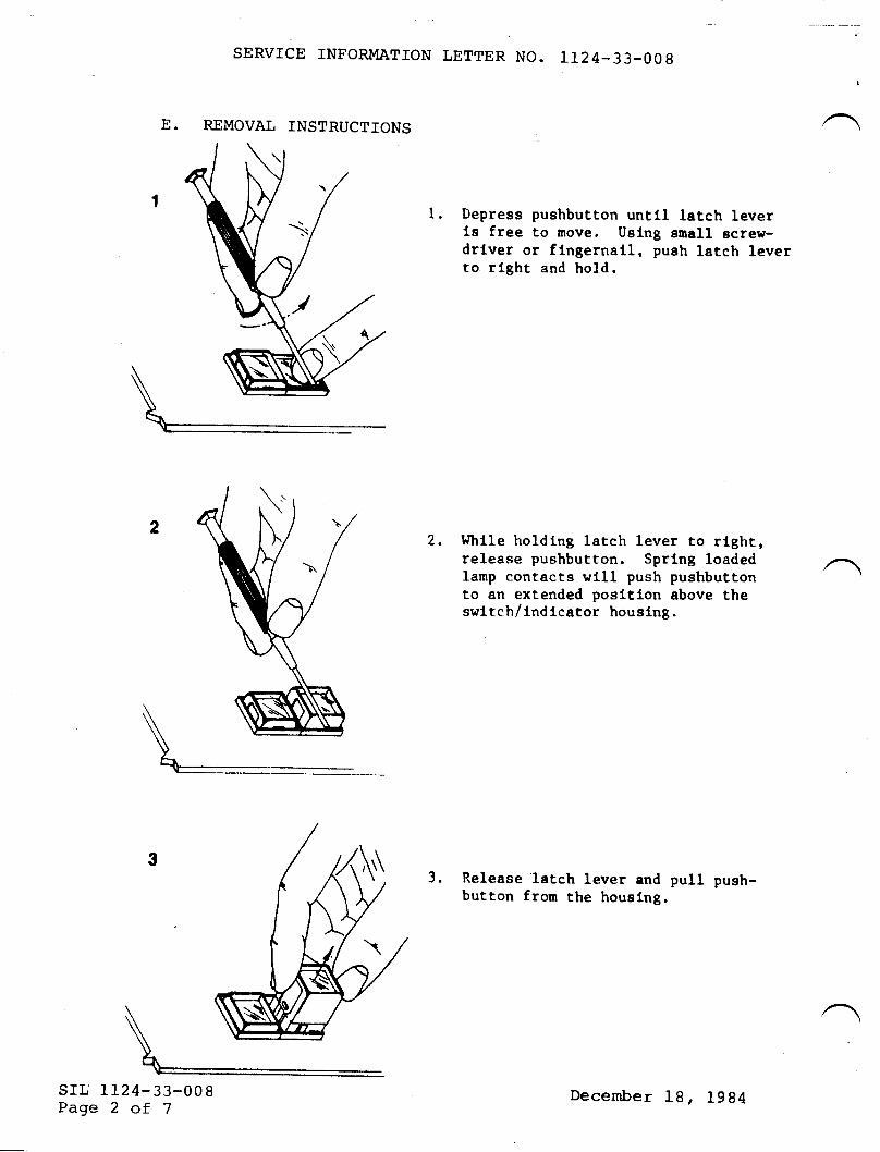
SERVICE INFORMATTON LETTER NO. LL24.33.008
E. REMOVAL INSTRUCTIONS
l. Deprees pushbutton untll latch leverle free to move. Uslng enall screlr-drlver or flngernall, pueh latch leverto rlght and hold.
2. Whlle holdtng latch lever to rlghr,release pushbutton. Sprlng loadedlanp contacts wll1 push pushbuttonto an extended posltlon above theswitch/lndicator housing.
3. Release latch lever and pull push-button from the houslng.
srl, I124-33-008Page 2 of 7
December 19, 1984
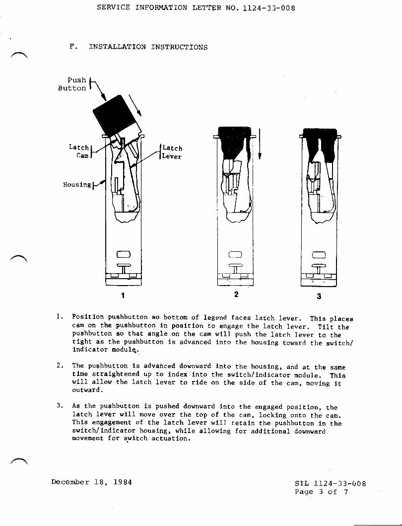
SERVICE INFORMATION LETTER NO. 1124-33-008
F. INSTALLATION INSTRUCTIONS
PushButton
LatchCaur
LatchLever I
l.
Housing
Posltlon Puehbutton so bottom of legend faces latch lever. Thts placeecam on the pushbutton ln posltlon to engage the lateh lever. TlLt thepushbutton so that angle on the can wlll push the latch lever to therlght as the pushbutton ls advanced lnto t.he houslng toward the swltch/lndlcator modulq.
The pushbutton ls advairced downward lnto the houslng, and at the sametlme stralghtened uP to lndex lnto the swltch/lndicator nodule. Thlswlll all-ohr the latch lever to rl.de on the side of the cam, moving ltoutward.
As the pushbutton ls pushed downward lnto the engaged positl-on, thelatch lever wLll rnove over the top of the cam, locking onto the cam.Thls engagement of the latch lever w111 retaln the pushbutton ln theswitch/lndlcator houslng, whlle allowlng for addttlonal domwardmovement for svitch actuatlon.
2.
3.
srl, 1124-33-008Page 3 of 7
December 18, 1984
SERVICE INFORMATION LETTER NO. IT24-33-OO8
cAUTroN: Do not force pushbutton into housing withoutarlowing the cam to move the latch lever into the properlocking position. Forcing the pushbutton may trap- thllatch lever between the cim and the housing lausiig thepushbutton to jam and be nonoperati_ve. rNStaLL LAMps rNPUSHBUTTON BEFORE INSERTING IN HOUSTNG. THIS TS IMPORTANTFOR EASY REMOVAL OF PUSHBUTTON.
G. Switch Body Removal and Installation
NOTE
It is recommended thatthe panel in which thedefective switch ismounted be removed toimprove accessibilityand prevent damage tosurrounding areas. , i
(I) Refer. to the appropriate wiring diagram.Identify wire and switch pin n,rmneri.(2) Cut wj-re tj-es and separate wire bundles. Unsol-der eachpin and tag each wire.(3) Remove screw from rear of switch body and push switchassembly through front of holder.(4) Reassembly is reverse of above steps.
H. Part Number Identification:(1) A11 lamp and pushbutton assemblies carry the rAr partnumber_883743-xx,
-where the -xX identifies the switchuse and engrave,d legend. This 993743 numbei can be-crossed to the basic STACO part number 44XXXX, 45XXXX t ot46xxxx, by reference to Figure I and/or Figure 2.(2) The srAco dash number identifying the switch use andlegend may be found stamped on tlie plastic lens assemblybody;- and, by looking inliae switch body,
"i"*p"d on thelamp base contactor p1ate.
srr, IL24-33-008Page 4 of 7
December 18, 1994
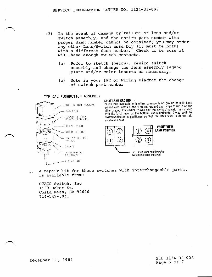
SERVICE INFORMATION LETTER NO. LL24-33-OO8
(3) In the event of damage or failure of lens and/orswitch assembly, and the entire part number withproper dash number cannot be obtainedi you may orderany other Lens/Switch assembly (it mtt.st be both)with a different dash number. Check to be sure itwill have enough switch contacts.
(a) Refer to sketch (beIow) , rewire switchassembly and change the lens assembly legendplate and/or color inserts as necessary.
(b) Note in your IPC or Wiring Diagram the changeof switch Part number
TYP I CAL PUSHBUTTON ASSEMBLY
ll I | -FACtPlAlttt+.l /*--:i -- -'^j|,i,ll,),' I i'J,lli,,
l: .. ::/. - ^-.:::'-< tt(,tNI) f,t Att-
" __.;<:)r._,-4:-E', c()t (\R trl r{ llsj '€' .i\| , , , I .L
Dt:,t't AY StRt FN
,+ Sar-t- . l)lvll)t lt
I '- 1r.,r,.". .. \It4.rn ' 1N -- (i^';hl I
ll 1i\* nl. i \-,'ttJ,,,ll,l ' \ lANll'r'r)AIil)I| ^'l;t
N4t,t Y
lill _,- \t YtN(i I lNtf-
A repair kit for theseis available from:
STACO Switch, Inc1139 Baker St.Costa Mesa, CA 926267r4-549- 30 41
SPLIT LAMP GR(IUND
irif,O,,tton available with either comnlon lamp groun{ or split lamp
ii*nd *iin ramos 1 and 4 on one ground and lamps 2 and 3 on the
,jinii oroJnO. foi vertical 2-way split the switch/indicator in installed
*iin riie iiiir' reuei it the botlom. For a horizontal 2-way split.the
switclr/indicator is positioned so that the latch lever is at the lett'
as shown above.
,- PIJSHI-]IJTTON HOUSING
I.
FROIIT VIEW
tAMP P(lSITION
Ref Latch lever Position when
switch/indicator installed.
switches with interchangeable Parts,
srr, LL24-33-008Page 5 of 7December 18, 1984
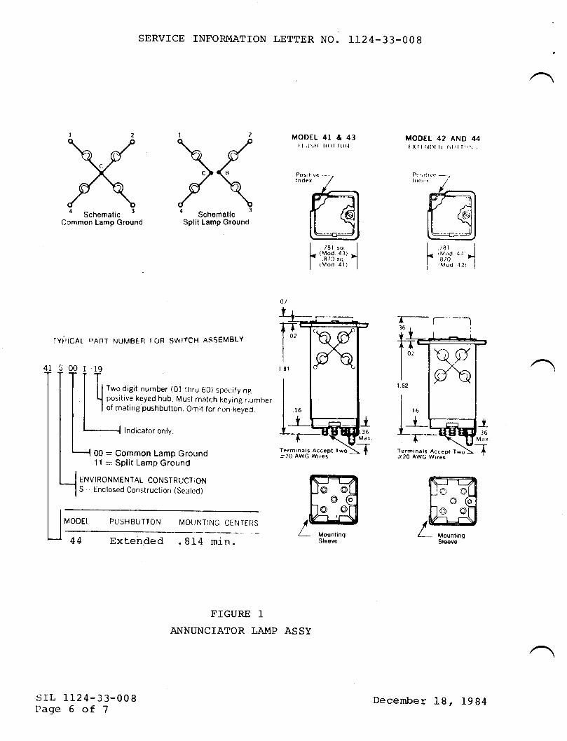
a Schematic 3
Common Lamp Ground
MODEL 42 AND 44tXTl r{t)l I) titlrl(}r-,,
T- a-']6
Terminals AcceDt lwoit20 AWG Wrrei
I rer'q I
l. 'Y93,i:' I| (Mod dl)
|
rYi,tcAI
4I SOOI
l*-T
Fmw,E.f$
,1-- MounlinqSle€ve Sleeve
srL tr24-33-008Pase 6 of 7
SERVICE INFORMATION LETTER NO. IL24.33-OO8
MODEL 4I & 43t I tJsll 8rr1 | or't
l2\J\c{\d\a Schematic 3
Split Lamp Ground
F'ANT NUMBER f OR SWITCH ASSEMBLY
10T
I
| | Two disit number (Ol tnru 60) specif ying
t positive keyed hub. Must match keying numberI of mating pushbutton. O,nit for non-keyed.
Indicator only.
00 = Common Lamp Ground11 =: $P111 LamP Ground
ENVIRONMENTAL CONSTRI-'CT ICIN
S , Enclosed Construction (Sealed)
MODEL PIJSHBUTTON MO(]NTING CENTERS
44 Extended .814 min.
FIGURE IA}INUNCIATOR LAMP ASSY
I rar
F'Y;tfI {Mod
Terminals Accept Two:20 AWG Wires
December 18, J-984
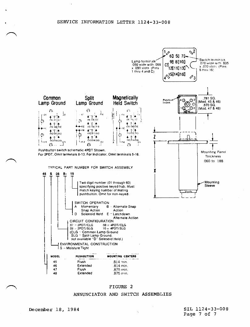
SERVICE INFORMATION LETTER 1I24-33-OO8
Lamp ternlinals.090 wide with .055x 090 slots. (Pins1 thru 4 ancl C)
)aro uo52
nn 9o 80t00"i2or1or3o\'
N15014016il
Switch ternlinals070 wide wrth 035x .070 slots (Pins5 thru 16)
2s
CommonLamp Ground
ol+-91+ "'A6 65i 6t
+ vi+$s 6aidro
+'T i+612dr ri 613
+ ?'tol5o14 bt6
Q1o_ _r
SplitLamp Ground
t-\Ir.. o 4
{-1? r+6o dslC,r
+iird9 08ldr0
L
+-T ita,l? 01 li 61 3
fY'tor5614 or6 or€L l-
MagneticallyHeld Switch 46)
48)
t r ,.,Fllti?I ll"'I l'r't,tlo L-:o
i["'iP.a{crr'loilL 'o'
.-. I(\) , I
i .\.+irt Ia6 \5,J7 )
+ ci+ rl
6s 6ri dro
+ ?ttJ'l 2 Cl ll dl3
+?i415dl4 b16
Q3nJ
*l]_
l-Pushbutton swilch schematic 4PDT Shown.For 2PDT, Omit terminals 8-13. For Indicalor, Omit terminals 5-16
YPICAL PART NUMBER FOR SWITCH ASSEMBLY
s08
Two digit number (01 through 60)specifying positive keyed hub. Mustmatch keying number of matingpushbutton. Omit for non-keyed.
SWITCH OPERATIONA Momentary B -,Alternate Snap
Snap Action ActionD Solenoid Held E .- Latchdown
Alternate ActionCIRCUIT CONFIGURATION07 = 2PDT/CLG 08 = 4PDT/CLG09 = 2PDT/SLG 10 = 4PDT/SLG(CLG .,Common Lamp GroundSLG -- Split Lamp Ground,not available "D" Solenoid Held.)
ENVIRONMENTAL CONSTRUCTIONS ,. Moisture Tight
PUSHEUITON TOUI{TII{G CEIITERS
B- 19
TTlLI
r_.1
i/IODEL
45464748
46
Mounting PanelTh ic kness
.060 to .188
MountingSleeve
L- -J
srl, 1L24-33-008Page 7 of 7
FlushExtendedFlushExtended
.814 min.
.814 min.
.875 min.
.875 min.
FIGURE 2
ANNUNCIATOR AND SWITCH ASSEMBLIES
19 B4
I
.781 so(Mod. 45 &
.870 so(Mod. 47 &
--rI
December 18,
I
SERVICE PUBLICATIONS
revision noticesrL NO. 1124-33-025Revision No. I September 9, 1985
ST,'B'JECT: FAILURE OF AIRCRAFT SYSTEM ATiTD I,AMP TEST FT'NCTIONS.
EFFEcrrvrrY: MODEL LL24 wEstritrNDs, alr seriar numbers.
REASON FORREvrsroN: To advise operators that diode p/N lN3Gr3is also approved as a replacement for the
original. P/N 1N645 diodes in the annunciatorpaneJ- modules.
/@Wwrmm**
sutgror^RY oF |SRAEL AtRCRAtt tNOUStntES. LrO3EN OURION AIFIPOR'. ISNA€L
srL 1124-33-025Page I of t
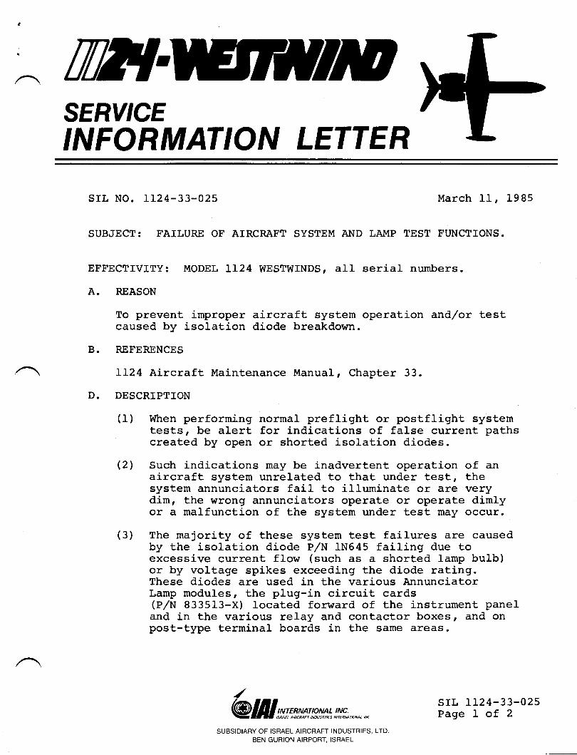
til?{SERY'CEINFORMATION LETTER
srr, No. 1124-33-025
SUBJECT: FAILURE OF ATRCRAFT SYSTEM Al{D LAMP
March 11, 1985
TEST FUNCTIONS.
EFFECTIVfTY: MODEL IL24 WESTWINDS, all serial numbers.
A. REASON
To prevent improper aircraft system operation and/or testcaused by isolation diode breakdown.
B. RETERENCES
LL24 Aircraft Maintenance Manual, Chapter 33.
D. DESCRIPTION
(1) When performing normal preflight or postflight systemtests, be alert for indications of false current pathscreated by open or shorted isolation diodes.
(2) Such indications may be inadvertent operation of anaircraft system unrelated to that under test, thesystem annunciators fail to illuminate or are verydim, the wrong annunciators operate or operate dimlyor a malfunction of the system under test may occur.
(3) The majority of these system test failures are causedby the isolation diode P/N IN645 failing due toexcessive current flow (such as a shorted lamp butb)or by voltage spikes exceeding the diode rating.These diodes are used in the various AnnunciatorLamp modules, the plug-in circuit cards(PrlN 833513-X) Iocated forward of the instrument paneland in the various relay and contactor boxes, and onpost-type terminal boards in the same areas.
/@ lI I g;::^r** mn : |n!!u";., *.,, *
SUBSIDIARY OF ISRAEL AIRCRAFT INDUSTRIES, LTD.
BEN GURION AIRPORT, ISRAEL
srl" IL24-33-025Page I of 2
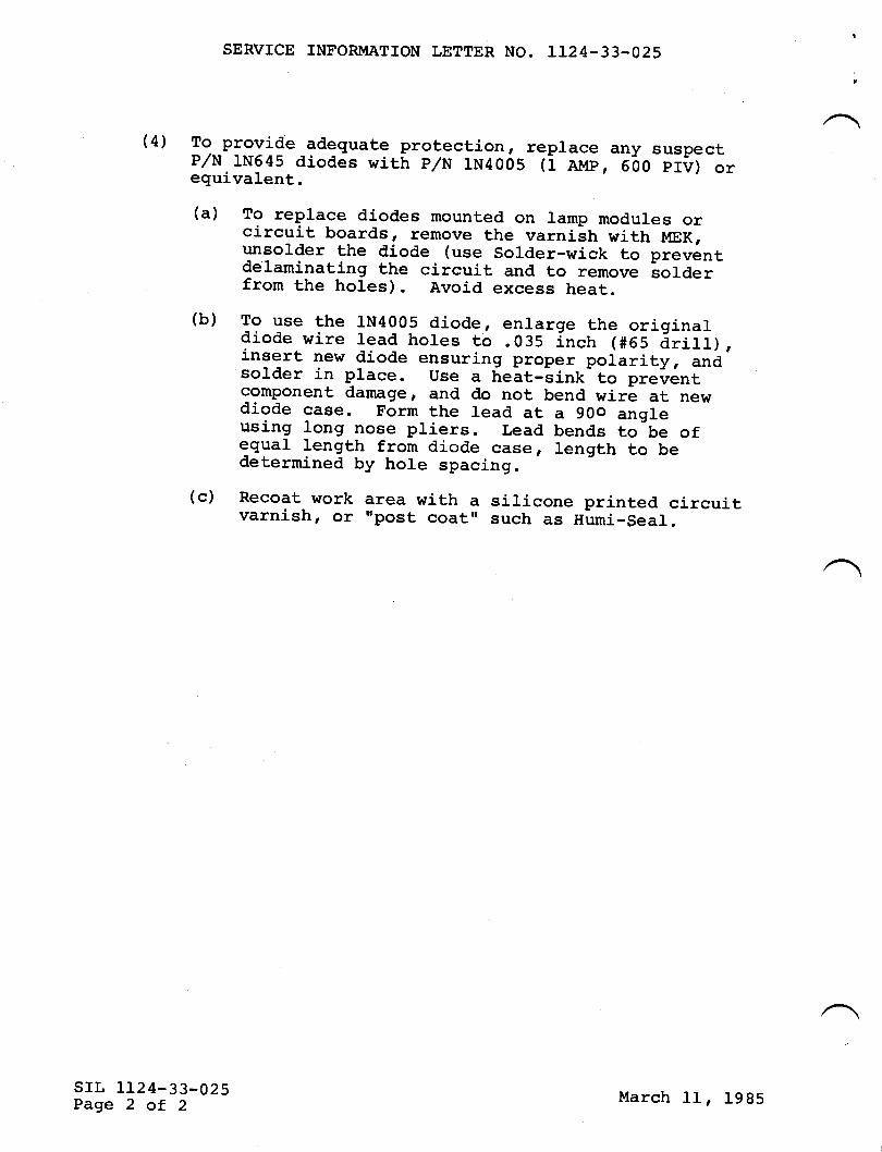
SERVICE INFORMATION LETTER NO. LL24-33-025
(4) To provide_adequate protection, replace any suspectp/N 1N645 diodes wirh p/N rN4005 ti arup, eoo pr?) orequivalent.
(a) To replace diodes mounted on ramp modures orcircuit boards, remove the varniitr wittr MEK;unsolder the diode (use Solder_wick to preventdelaminating the circuit and to remove sorderfrom the holes). Avoid excess heat.(b) To use the 1N4005 diode, enlarge the originardiode wire lead hotes to .035 Inch (#65 drilt),insert new diode ensuring proper polarity, andsolder in prace. use a helt-iink to preirent
component damage, and do not bend wire at newdiode case. Form the lead at a 90o angleusing long nose pliers. Lead bends to be ofequal length from diode case, length to bedetermined by hole spacing.(c) Recoat work area with a siricone printed circuit
varnish t ot ,,post coatr, such as Humi_Seal.
srr, LL24-33-025Page 2 of 2
March 11, 1985
ril?{SERY'CEINFORMATION LETTER
A.
SERVICE INFORMATION TETTER NO. 1124-33-032 JULY 8, 1988
SUBJECT: LIGHTING - COCKPIT GLARESHIELD - FLOODLIGHTIMPROVEMENT.
EFFECTIVITY: l,tODEL llZq/1124A WESTI{IND, all serial numbers.
c.
REASON
To alert 112411124A operators that a Service Bulletin hasbeen published by Aerospace f,ighting Corporation againsttheir fluorescent lamps with certain part numbers. Due tothe possibility of higher than normal temperatures at theIamp ends caused by filament degradation, the manufacturerhas recommended a modificatj-on to the lamp ends to reduce theheat stress.
REFERENCES
Attached Aerospace Lighting Corporation Service Bulletin No.ALC-SB-004 issued 23 Dec 8'l .
PUBLICATIONS AFFECTED
1124/1124A Maintenance ManuaI Chapter 33-1 0-00, MaintenancePractices.
@ lI I g^r:*rg p**l !nt*;., *.,, * srl, 1124-33-032Page 1 of 2
B.
/
SUBSIDIARY OF ISRAEL AIRCRAFT INDUSTRIES, LTD
BEN GURION AIRPORT, ISRAEL
SERVICE INFORMATION LETTER NO. 1124-33-032
D. DESCRIPTION
The additionar heat that may be generated may cause lamp-endcracks which will expose the lamp filaments. The addition ofthe Teflon shrink Tubing to the ramp ends wirl aid in thedistribution of heat and prevent shattering.AII flood lamp assemblies delivered by ALC after Dec 87 willhave the retro-fit incorporated during manufacture accordingto Aerospace Lighting Corporation.
srl, 1124-33-032Page 2 of 2
JuIy 8, 1988
AEROSPACE LIGHTING CORPORATION
SERVICE BULLETINNUMBER: ALC-SB-Og4
APPLICABILITY:
ISSUE DATE Z 23 DEC 87 REVISION DATE: ll,/n
AII cockplt, fluore6cenL floodltght, aesemblles manufacEured byAerospace f,ighttng Corporatlon bearlng the Part Nurnbers llst'ed inAttachment A.
IDENTIFICATION: (See Flgures Al, A2)
Floodllght assemblles whlch have been retro-flt,ted will beidentified by a blue dot palnt marklng located ln Lhe white spacenext to the Lerlal number (see Figure A2). A second doL will belocated on the face of the buckeE aseembly (See Flgure Af) toallow identiflcatlon wlthout removlng Ihe floodllght assemblyfrom Ehe aircraft. New floodltght aesembllee whlch have the/ \ retro-flt Lncorporabed aE manufacturlng wlll aLso be marked witha blue palnE dot ln both deslgnaLed areaa.
SUBJECT:
Retro-fiE teflon shrlnk tublng Eo the ende of the fluorescentlamps ln the lleted floodltght assembliee t,o prevent exposing thefllamenLs in the event of lamp fallure.
COIIIPLIANCE:
DISCUSSION:
Extenslve laboratory and fleld testlng hg" lndlcated thatfluorescent lamps which have htgh operat,lng t,lme and/or filamenLdegradation may produce hlgher - t,han normal temperaturest at thelamp ends. T[e addltlonal heaE sbrega may caucte the lamps tocrack near Ehe end Lhereby exposlng the lamp fllamenE' Theadditlon of teflon ehrlnk -tublng to Ehe lamp end wlll ald in
A dlstributlon of the heat, along the lampr thereby reduclng the
' \ h;;i rti"rr. Further, tf the limp ehould fallr t'he t'eflon shrink
tubing wlll prevent shattertng and exPoaure of the Iampfllaments.
I.2.
optlonal/Recommended In fieldt'tindaEory by ALC Repalr Statlon for assembliessent Eo ALC f or test,1n9,/rePalr.
Page I of 3
CLASSIFICATION:
The retro-flt does not affecB form' flE or funcEion and ist,herefore claselfled as ml.nor ln nat,urd.
}IEIGHT AND BALANCB:
Negltgtble leea than 6.L ouncesr
TIME AND MATERIALS:
Estlmated tlme Eo complete the retro-flt procedure leapproxlmately 3O mlnutes. - Thle does not lnclude access/removal/lnstallatlon tlme on the alrcraft.
DESCRIPTION OF MATERIAL AND TOOLS REQUIRED:
l. FEP teflon ehrlnk tublng equlvalent toATPHA l{rRE CORPORATTON P/N Err-Aog-A7lt Lldgerwood Avenue/P.o. Box 7llgllzabeih, New Jersey O72O7 (2OI'l 925-8agg
2. Keeter n44" Resln Core Solder sN60 or eqUlValent.
3. Ineulat{ng varnl.th equlvalent to nRed GLPTIneulating Varnlgh" r lllolluf actured by GC Elec tronlc rRockfordr IL 61105; (8I5) 968-4661- P/N I0-9OO2.
4' :i::[:l.i:'::;irl"iin:'.1313]trver 176oc and common
INSTRUCTIONS:
Complete retro-flt lnetruct,lone and llluet,raElons are lncluded inAttachment, B.
FOR FURTHER INFORI.IATION:
AEROSPACE TIGHTING CORPORATIONlOI-8 Colln Drlve
Holbrookr New York 11741( sr6 1563-64sA
Telex: 64-5135Fax: (Sfe)563-878f
ALC-SB-004 ( Cont )
Page 2 of 3
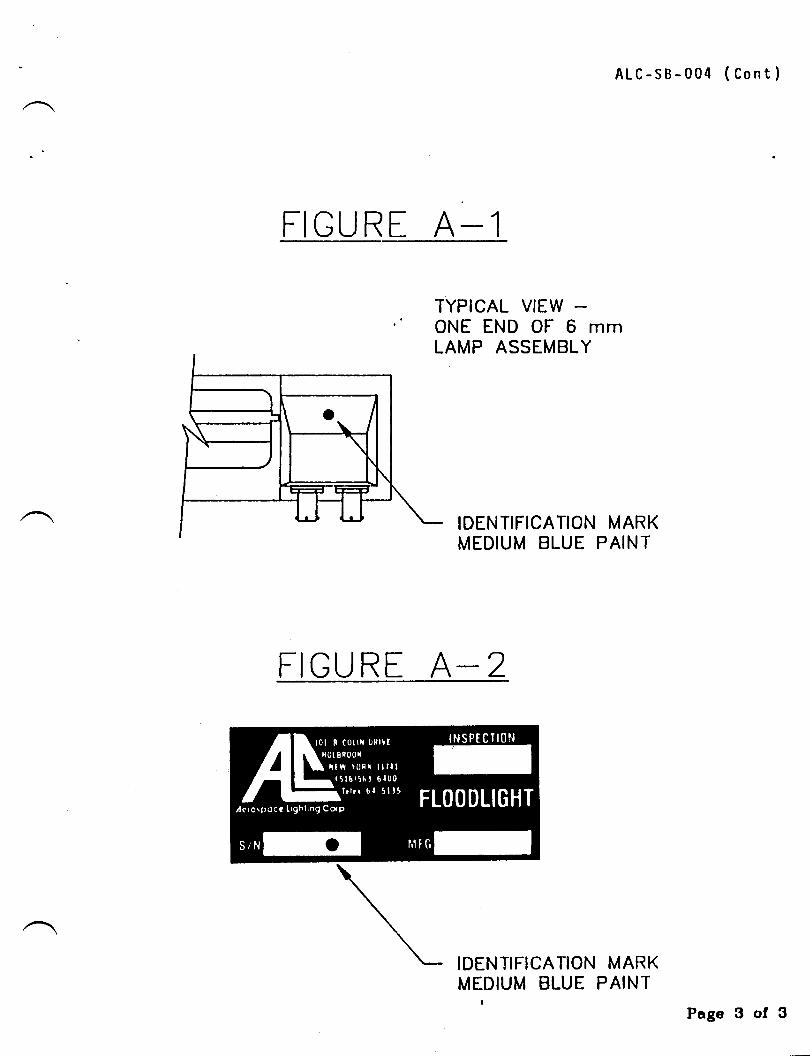
FI GURE A-1
ALc-sB-004 ( Cont )
MARKPAINT
Page 3 of 3
TYPICAL VIEWONE END OF 6 mmLAMP ASSEMBLY
FIGURE A-2
IDENTIFICATION MARKMEDIUM BLUE PAINT
IDENTIFICATIONMEDIUM BLUE
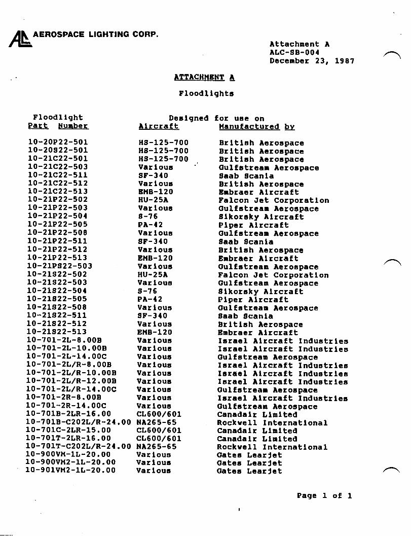
/L o=RosPAcE LlGHrtllG coRP.
FloodI lghtPart Nunber
10-20P2 2-501LO-20s22-501LO-2LC22-501LO-2LC22-50310 -2 1C2 2 - 511LO-2Lc22-5L210-21C22-513LO-2LP22-50210 -2lP 2 2 -50 3LO-zLP22-501LO-2LP22-505LO-2LP22-508LO-2LP22-511t0-ztP22-5t210-2lP22-51310-2lPs22-50310-21S 22-50210-21S 22-50310-21S 22-50110-2ls22-505LO-2L822-508LO-2t822-51110-21S 22-5L2L0-2L522-51310-701-2L-9.00810-701-2L-10 . 00810-701-2L-1{ .00c10-701-zL/R-8.00810-701-zt/R-10.00810-?01-2r,/R-L2. 00810-701-2L,/R-11 .00C10-701-2R-8.00810-701-2R-1{.00c10-7018-zLR-16 . 0010 -? 018 -C202L / R- 2 | . 0 010-70lc-2LR-15 . 0010-?01T-2LR-16.0010-? 01T-C202L/R-2 | . 00l0-900vH-1L-20 . 0010-900VH2-L',-20 . 001Q-901VH2-lt -20.00
Attachnent AALC-SB-001Dccenbcr 23, 198?
ATTACHHETfT tr
Floodl lghtg
DeelgnedAlrcrattHs -1 2 5-? 00H8-125-700Hn-125-?00Ver I oursF-3t0Var louaBD|B-120HU-25AVar loua8-?6PA-I 2Var lous8F-3t0Var I ouaEHB-120Var I ouaHU-25AVar I ougs-?6PA-I 2Var lousgF-310Var lousEHB-120Var IousVar I ouaVar louaVartouaVar loucVar I ouaVar lousVar t oucVar louccr600/601NAz65-55cL600/601cL600,/601Nr265-65Var lousVar I ourtVar loua
for uae onHanufactured IBrltlsh AerocpaceBrlttgh AeroapaceBrltlah Acrolpac€Gulfatrcan AeroapaceSaab ScanlaBrltl;h AcrorpaceErbracr AlrcraftFalcon Jet CorporatlonGulfatreaa AerorpaceSlkorahy AlrcraftPlpcr AlrcraftGulfatrcan AeroapaceSaab ScanlaBrltlah lcroapaceErbraer Alrcra[tGulfatraaa AerospeceFalcon Jct CorporatlonGulfatrean AeroEpeceSlkoraky AlrcraftPtper AlrcraftOulfstrcan AarolpaceSaab ScanlaBrltlsh AerospaceEnbracr AlrcraftIcrecl Alrcraft IndustrlesIaracl llrcraf,t IndustrlesOulfgtrcan Aeroapacelarecl Alrcraft IndugtrtegIarael Alrcraf,t lndustrlegIaracl Alrcraf,t IndustrlesGulfatrean AcrospaceIaracl Alrcraf,t IndustrlesOulfatrcan lerospaceCanadalr LlnltedRockvell IntcrnatlonalCanadalr LlnltedCanadalr LlultedRockvcll IntcrnatlonalGateg LcarJetGatcc LcarJetGatca LcarJct
Page 1 of 1
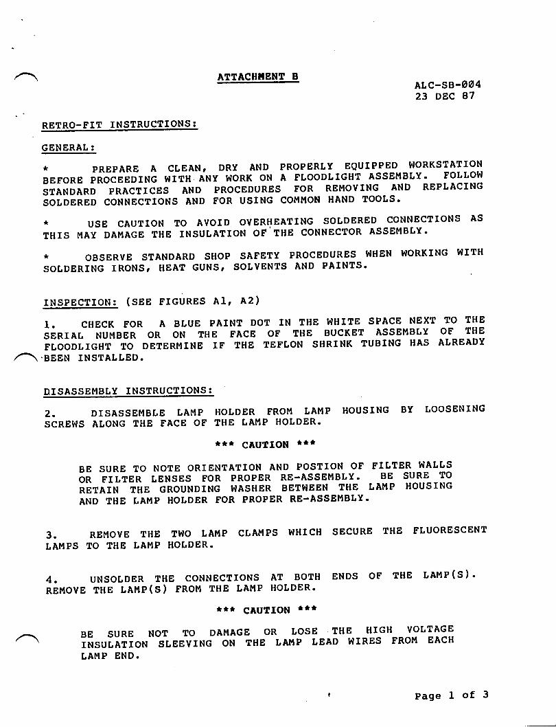
ATTA.HIfENT B ALc-ss-ag'23 DEC 87
RETRO-FIT INSTRUCTIONS :
GENERAL:
*PREPAREAcLEAN'DRyANDPRoPERLyEQUIPPEDWoRKSTATIoNBEFORE PROCEEDING WITH ANY WORK ON A FTOODTIGHT ASSEMBLY' FOLLOIiI
STANDARD PRACTICES AND PROCEDURES FOR REMOVING AND REPLACING
SOLDERED CONNECTIONS AND FOR USING CO}II'ION HAND TOOLS'
* USE CAUTION TO AVOID OVERHEATING SOLDERED CONNECTIONS AS
THIS MAY DAMAGE THE INSUTATION OF.THE CONNECTOR ASSEMBLY'
* OBSERVE STANDARD SHOP SAFETY PROCEDURES 9IHEN }IORKING }IITH
SOLDERING IRONS' HEAT GUNS' SOLVENTS AND PAINTS'
INSPECTION: (SEg FIGURES A1, A2)
1. CHECK FOR A BLUE PAINT DOT IN THE WHITE SPACE NEXT TO THE
SERIAL NUMBER OR ON THE FACE OF THE BUCKET ASSEMBLY OF THE
FLOODLIGHT TO DETERMINE IF THE TEFLON SHRINK TUBING HAS ALREADY.BEEN INSTALLED.
DISASSEI,IBLY INSTRUCTIONS :
2. DISASSEMBLE LAtiIP HOLDER F'ROTiI LAMP HOUSING BY LOOSENING
SCREWS ATONG THE FACE OF THE LAMP HOLDER.
ttr CAUTIoN tt*
BE SURE TO NOTE ORIENTATION AND POSTION OF FILTER WALLS
OR FILTER TENSES FOR PROPER RE-ASSEMBLY' BE SURE TO
RETAIN THE GROUNDING WASHER BETI{EEN THE LAT'IP HOUSING
ANDTHELAMPHoLDERFoRPRoPERRE-ASSEMBLy.
3. REMOVE THE TT{O LAMP CLAMPS }IHICH SECURE THE FLUORESCENT
LAMPS TO THE LAMP HOLDER.
4. uNsoLDER THE coNNecrroNs AT BorH ENDs oF THE LAMP(s).REMOVE THE LAMP(S) FROM THE LAMP HOLDER'
It* CAUTION ttt
BESURENoTToDAMAGEoRLosETHEHIGHVoLTAGE. INSULATION SLEEVING ON THE tN'tP LEAD WIRES FROT'T EACH
LAMP END.
Page 1 of 3
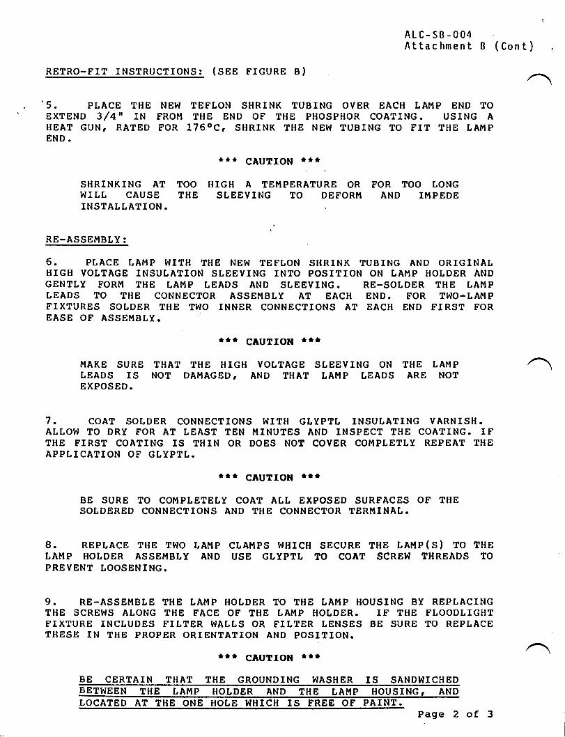
ALC-SB.OO4Attac hment B (
RETRO-FIT INSTRUCTIONS: (SEE FIGURE B)
'5. PLACE THE NEW TEPLON SHRINK TUBING OVER EACH LAMP END TOEXTEND 3/4" IN FROII THE END OF THE PHOSPHOR COATING. USING AHEAT GUN, RATED FOR I76OCI SHRINK THE NEW TUBING TO FIT THE LAMPEHo.
SHRINKING AT TOOWIIL CAUSE THEINSTALLATION.
RE-ASSEMBLY:
t*t CAUTION ttt
TIIGH A TEMPERATURE OR FOR TOO tONGSLEEVING TO DEFOR},I AND IMPEDE
6. PLACE LAMP WITH THE NET^I TEFLON SIIRINK TUBING AND ORIGINALHIGH VOTTAGE INSULATION SLEEVING INTO POSITION ON LAMP HOLDER ANDGENTLY FORM THE LAMP TEADS AND SLEEVING. RE-SOLDER THE LAMPtEADS TO THE CONNECTOR ASSEMBLY AT EACH END. EOR TWO*LAMPFIXTURES SOLDER THE TWO INNER CONNECTIONS AT EACH END FIRST FOREASE OF ASSEMBLY.
ttt cAuTIOll trt
MAKE SURE THAT THE HIGH VOLTAGE SLEEVING ON THE LAMPLEADS IS NOT DAMAGED I AND THAT LAT.IP LEADS ARE NOTEXPOSED.
7. coAT SoLDER coNNEcTIoNs l{ITH GtyPTL INSULATING VARNISH.ALLOVI TO DRY FOR AT LEAST TEN MINUTES AND INSPECT THE COATING. IFTHE FIRST COATING IS THIN OR DOES NOT COVER COMPLETLY REPEAT THEAPPLICATION OF GtYPTt.
trr CAUTION trr
BE SURE TO COMPLETELY COAT ALL EXPOSED SURFACES OF THESOLDERED CONNECTIONS AND THE CONNECTOR TERMINAL.
8. REPTACE THE TI{O LAMP CTAMPS WHICH SECURE THE LAMP(S) TO THELAMP HOTDER ASSEMBLY AND USE GLYPTT TO COAT SCREW THREADS TOPREVENT LOOSENING.
9. RE-ASSEMBLE THE tAMP HOLDER TO THE LAMP HOUSING BY REPLACINGTHE SCREWS ALONG THE FACE OF THE LAMP HOLDER. IF THE FLOODLIGHTFIXTURE INCLUDES FILTER WALLS OR FILTER LENSES BE SURE TO REPLACETHESE IN THE PROPER ORIENTATION AND POSITION.
Itt CAUTION llt
BE CERTAIN THAT THE GROUNDING WASHER IS SANDWICHEDBETWEEN THE LAMP HOLDER AND THE LAMP HOUSING, ANDLOCATED AT THE ONE HOLE I{HICH IS FREE OF PAINT.
Page 2
Cont) .
of3
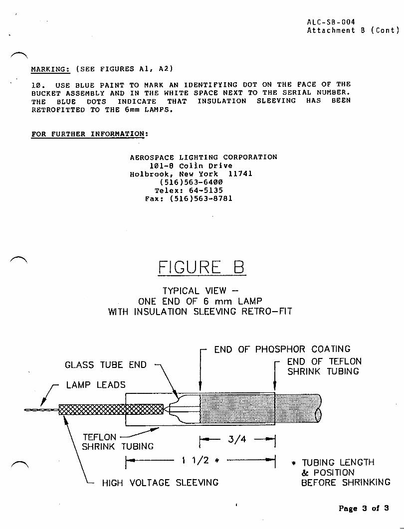
MARKING: (SEE FIGURES AI, A2)
LA. USE BLUE PAINT TO MARK AN IDENTIFYING DOT ON THE FACE OF THEBUCKET ASSEMBLY AND IN TIIE WHITE SPACE NEXT TO THE SERIAL NUMBER.THE BLUE DOTS INDICATE THAT INSULATION SLEEVING HAS BEEN
RETROFITTED TO THE 6MM LA['IPS.
FOR FURTHER INFORT.IATION:
AEROSPACE LIGHTING CORPORATIONlOl-8 ColIn Drlve
Holbrookr New York 11741( 516 1563-6400
Telex:64-5135Fax: (5f6)563-8781
FIGU RE BTYPICAL VIEW
ONE END OF 6 mm LAMPWITH INSULATION SLEEVING RETRO-FIT
END OF
GLASS TUBE END
LAMP LEADS
ALC-SB-004Attachment B (Cont)
* TUBING LENGTH& POSITIONBEFORE SHRINKING
PHOSPHOR COATING
r END OF TEFLONI sHntrux ruBtNGI
I
TEFL9N /SHRINK TUBING r- 3/4 --
1 1/2 *
HIGH VOLTAGE SLEEVING
Page 3 of 3
TW{SERY'CEINFORMATION LETTER
srr, No. II24-33-058 Sepbember 27, 1985
RADIATION FROM CABTN FLUORESCENTSUBJECT: ELECTRICAL NOISELIGHTING SYSTEM
A.
EFFECTIVITY: MODEL LI24/LL24A WESTWIND, all serial numbers
REASON
To eliminate noise from the cabin lighting system, especiallywhen the preset rrDIM'r condition is selected. This noise isradiated into many aircraft systems, and has a severelyadverse effect on VLF, ADF and HF receiver systems installed.The effect is to limit the receiver range, causing loss ofnavigation and/or errors at low system signal Ievels, otbreaking the squelch and causing noisy communicationsreception.
REFERENCES
IL24/LL24A Wiring Diagram Manual, Chapter 33-20-02
II24/LL24A Illustrated Parts Catalog, Chapter 33-20-00
PUBLICATIONS AFFECTED
None
DESCRIPTION
This service information letter contains troubleshootinginformation relevant to correcting the sources of theradiated noise.
SIL II24-33-O58Page 1 of 3
@ III srmsp*t* |,!Y;,*,,*
SUBSIDIARY OF ISRAEL AIRCRAFT INDUSTRIES, LTD.
BEN GURION AIRPORT, ISRAEL
B.
c.
D.
/
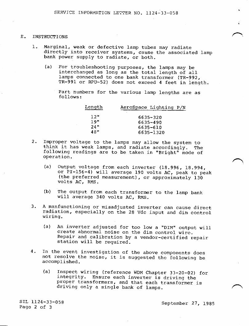
E.
SERV.ICil INFORI"IATTON LETTER No. 1124-33-058
INSTRUCTTONS
Marginal, weak or defective lamp tubes may radiatedirectly into receiver systems, cause the associated lampbank power supply to radiater or both.(a) For troubleshooting purposes, the lamps may be
interchanged as long as the total length of alllamps connected to one bank transformer (TR-992,TR-991 or RPU-52) does not exceed 4 feet in length.Part numbers for the various lamp lengths are asfollows:
1.
Length
I2"19"24"4g"
AeroSpace Lighting P/N
6 6 35-32 06635-4906 6 3s-61066 35-1 32 0
2. fmproper voltage to the lamps may al1ow the system tothink it has weak lamps, and radiate accordingly. Thefollowing readings are to be taken in "Bright" mode ofoperation.
(a) Output voltage from each inverter (19.996, Ig.g94,or Pf-155-4) will average 190 volts AC, peak to peak(the preferred measurement) r or approximltety 130volts AC, RMS.
(b) The output from each transformer to the lamp bankwill average 340 volts AC, RMS.
3. A manfunctioning or misadjusted inverter can cause directradiation, especj-arly on the 2g vdc input and dim controlwiring.(a) An inverter adjusted for too 1ow a "DrM" output willcreate abnormal noise on the dim control wire.
Repair and calibration by a vendor-certified repairstation will be required.
rn the event investigation of the above components doesnot resolve the noise, it is suggested the folrowing beaccomplished.
(a) rnspect wiring (reference wDM chapter 33-20-02) forintegrity. Ensure each inverter is driving theproper transformers, and that each transformer isdriving only a single bank of lamps.
4.
SIL TL24-33-O58Page 2 of 3
September 27, 1985
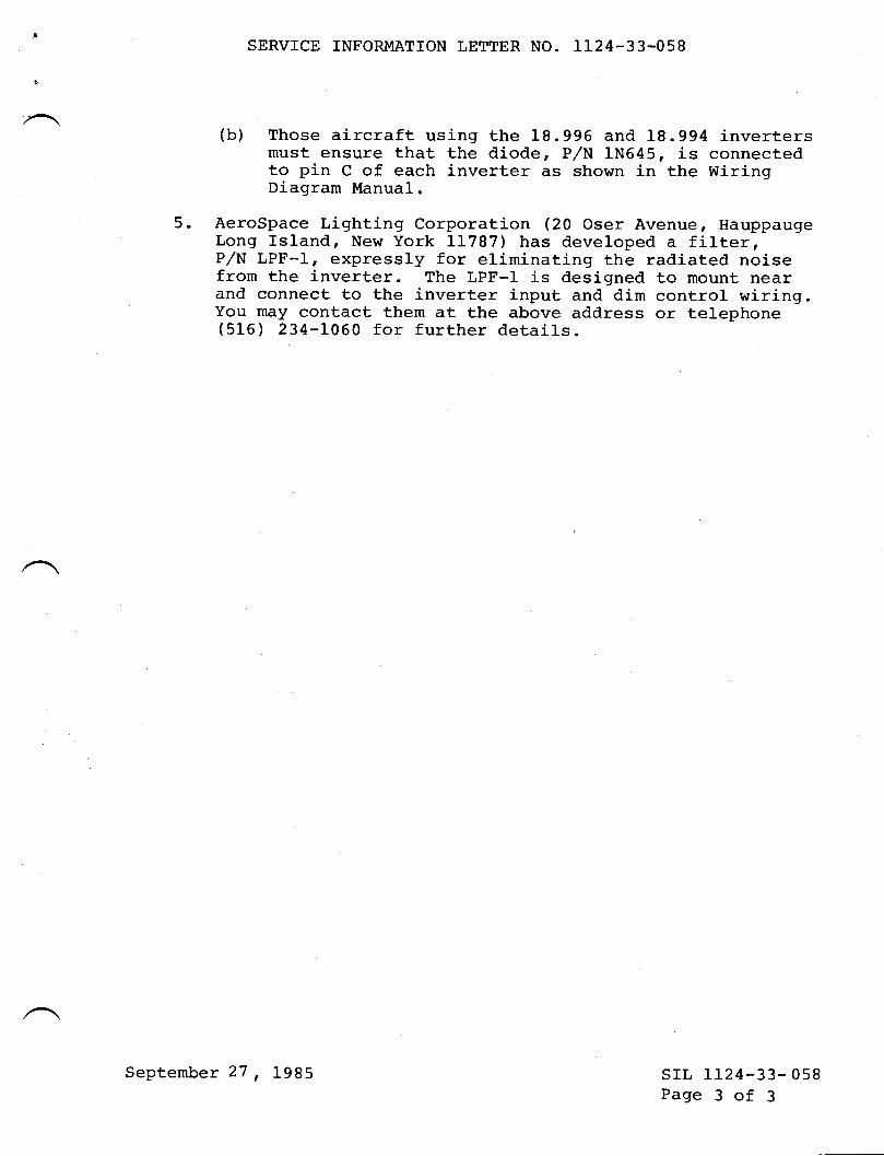
SERVICE INFORMATTON LETTER NO. LI24-33-058
(b) Those aircraft using the 18.996 and 18.994 invertersmust ensure that the diode, P/N 1N645, is connectedto pin C of each inverter as shown in the WiringDiagram Manual.
5. AeroSpace Lighting Corporation (20 Oser Avenue, HauppaugeLong Island, New York J-1787) has developed a filter,P/N LPF-I, expressly for eliminating the radiated noisefrom the inverter. The LPF-I is designed to mount nearand connect to the inverter input and dim control wiring.You may contact them at the above address or telephone(516) 234-L060 for further details.
srl, 1124-33- 058Page 3 of 3
September 27, 1985
I
SERY'CEINFORMATION LETTER
SEN.VICE INFORMATION LETTTR NO. 1124-33484 December L2, 1990
SU&IECT: LIGHTING - TIP TANK STROBE LIGIIT WIRING
EFFECTIVITY: MODEL LL24lll24A, all serial numbers.
A. REASON
To caution operators of possible wire chafing in strobe light recess aftermaintenance.
B. REFERENCE
1.l24lll24A Westwind Wiring Diagram Manual, Chapter 3340{1.
C. PUBLICATIONSAFFECTED
LL24ll124A Westwind Maintenance Manual, Chapter 33-40-00, Paragraph 68will be revised to include this caution.
D. DESCRIPTION
Replacement strobe lamp assembly P/N 3l-3L12-11 is equipped with a 20 inchshielded cable assembly.
This cable assembly is normally doubled back and tied together at installation, toprevent chafing to adjacent structure or being inadvertently pinched duringreassembly of access panels.
Please observe this precaution should replacement of strobe light assembly be
required.
Derember 12,1990LO24
sL 1t24-33484Page I of 1
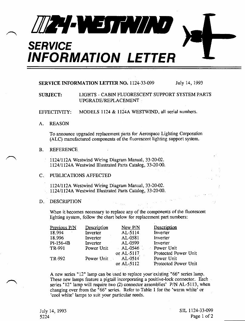
TWTSERY'CEINFORMATION LETTER
SERVICE INFORMATION LETTER NO. 1124-33-099 July 14, 1993
ST]BJECT:
EFFECTTVITY:
Iuly 14, 1993
5224
LIGHTS - CABIN FLUORESCENT SUPPORT SYSTEM PARTS
UPGRADE/REPLACEMENT
MODELS Il24 & ll24L WESTWIND, all serial numbers.
A.
B.
C.
D.
REASON
To announce upgraded replacement parts for Aerospace Lighting Corporation(ALC) manufactured components of the fluorescent lighting support system.
REFERENCE
ll24ll12A Westwind Wiring Diagram Manual, 33-2042.ll24ll124A Westwind Illustrated Parts Catalog, 33-20{0.
PUBLICATIONS AFFECTED
ll24ll12A Westwind Wiring Diagram Manual, 33-2042.Il24lll24A Westwind Illustrated Parts Catalog, 33-20{0.
DESCRIPTION
When it becomes necessary to replace any of the components of the fluorescentlighting system, follow the chart below for replacement part numbers:
Frevious P/N Description New P/N18.994 Inverter AL-51l418.996 Inverter AL-0581PI-15648 Inverter AL-0599TR-991 Power Unit AL-0546
or AL-5117TR-992 Power Unit AL-0514'
or AL-5112
DescriptionInverterInverterInverterPower UnitProtected Power UnitPower UnitProtected Power Unit
A new series "12" lamp can be used to replace your existing "66" series lamp.These new lamps feature a pigtail incorporating a positive-lock connector. Eachseries "12" lamp will require two (2) connector assemblies' P/N AL-5113, whenchanging over from the "66" series. Refer to Table 1 for the 'warm white' or'cool white' lamps to suit your particular needs.
str- 1124-33-099Page I of 2
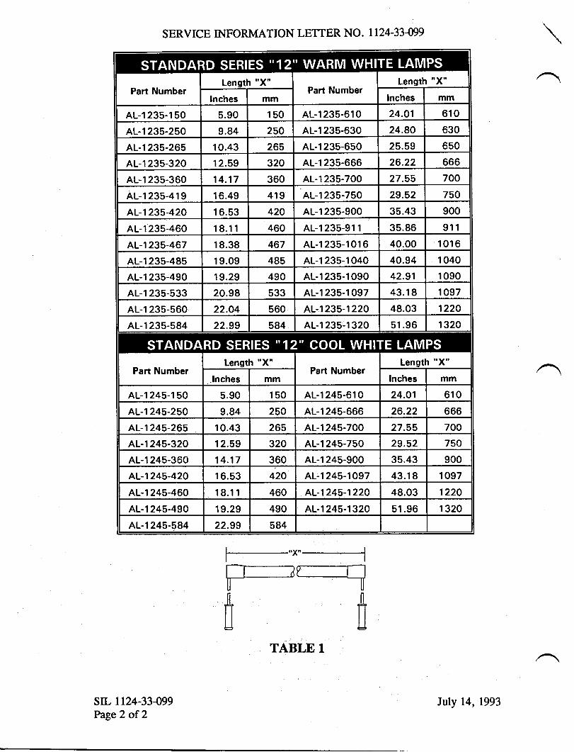
SERVICE INFORMATION LETTER NO. 1124-33-O9
Part NumberLenoth "X"
Part NumberLength "X'
Inches mm lnches mm
AL-1235-150 s.90 150 AL-1235-610 24.O1 610
AL-1235-250 9.84 250 AL-1235-630 24.80 630
AL-1235-265 10.43 265 AL-1235-650 25.59 6s0
AL-1235-320 12.59 320 AL-1235-666 26.22 666
AL-1235-360 14.17 360 AL-1235-700 27.55 700
AL-l235-419 16.49 419 AL-1235-750 29.52 750
AL-1235-420 16.53 420 AL-1235-900 35.43 900
AL-1235-460 18.11 460 AL-l235-911 35.86 911
AL-1235-467 18.38 467 AL-1235-1016 40.00 1016
AL-1235-485 19.09 485 AL-1235-1040 40.94 1 040
AL-1235-490 19.29 490 AL-1235-1090 42.91 1 090
AL-1235-533 20.98 533 AL-1235-1097 43.18 1 097
AL-1235-560 22.O4 560 AL-1235-1220 48.03 1220
AL-1235-584 22.99 584 AL-1235-1320 51.96 1 320
Part NumberLensth "X"
Part NumberLenqth "x"
.lnches mm Inches mm
AL-1245-150 5.90 150 AL-1245-610 24.O1 610
AL-1245-250 9.84 250 AL-1245-666 26.22 666
AL-1245-265 10.43 26s AL-1245-700 27.55 700
AL-1245-320 12.59 320 AL-1245-750 29.52 750
AL-1245-360 14.17 360 AL-1245-900 35.43 900
AL-1245-420 16.53 420 AL-1245-1097 43.18 1 097
AL-1245-460 18.11 460 AL-1245-1220 48.03 1220
AL-1245-490 19.29 490 AL-1 245-1 320 51.96 1320
AL-1245-584 22.99 584
F-----ftfi
str. 1t24-33499Page2 of 2
TABLE 1
Iuly 14, 1993
TW{SERY'CEINFORMATION LETTER
sIL NO. tt24-33-099 REVISION 2
TRANSMITTAL SHEET
December 13, 1995
This sheet transmits Revision 2 to Service Information Letter No. I 124-33-099 datedJuly 14, 1993, titled "Lights - Cabin Fluorescent Support System PartsUpgrade/Replacement".
REASON FOR REVISION
To provide maintenance personnel with Aerospace Lighting Corporation's InformationBulletin No. 92-001, titled "Upgrading Series 66 Fluorescent Lighting Systems withN--I2 Series Lamps."
This is a COMPLETE REVISION. Please remove and discard all pages of previousissues and replace with the pages of this revision.
LIST OF EFFECTTVE PAGES
PAGE NO.
I2
DATE
December 13, 1995
December 13, 1995
PREVIOUS REVISIONS OF SIL NO. I124.05.088
Revision l, May 25,1994
TransmittalPage I ofl
December 13, 1995
TTTISERVICEINFORMATION LETTER
SERVICE INFORI\,TATION LETTER NO. 1 T24.33.099 Iuly 14, 1993
SUBJECT: LIG}ITS . CABIN FLUORESCENT SUPPORT SYSTEM PARTSUPGRADE/REPLACEMENT
MODELS ll24 I lL24 AWESTWIND S, all serial numbers.EFFECTIVITY:
A. REASON
To announce upgraded replacement parts for Aerospace Lighting Corporation(ALC) manufactured components of the fluorescent lighting support system.
B. REFERENCE
| 124 | | 124 A Westwi nd Wi ri ng Di agram Manual, 33 -20 -02.
| 124 / | 124 A Westwind Il lustrated Parts Catal og, 3 3 -20-00.| 124 / | 124 A Westwind Service Informati on Letter No. I I 24-3 3 -05 8.
I 124 / | 124 A Westrvind Service B ulleti n No' s. | 124-33 -l2l &, | 124 -33 - I 3 I .
Aerospace Li ghting Corporati on Informati on Bull etin No. 92-00 l, "UpgradingSeries 66 FluorescentLighting Systems with AL-12 Series Lamps."
C. PUBLICATIONSAFFECTED
| 124 / | I24 A Westrvi nd Wi ri ng Di agram Manual, 33 -20 -02.
| 124 I | 124 A Westwind II lustrated Parts Catal og, 3 3 -20-00.
D. DESCRIPTION
When it becomes necessary to replace any of the components of the fluorescent
lighting system, refer to the following chart for replacement part numbers:
NOTE: Reference Service Bulletin 1124-33-12l for installation instructions forProtected PowerUnits P/N AL-s117 & AL-5112.
RRR
RR
July 14, 1993Revision 1, May 25,1994
R Revision 2, December 13, 1995sIL 1124-33-099
Page I of2
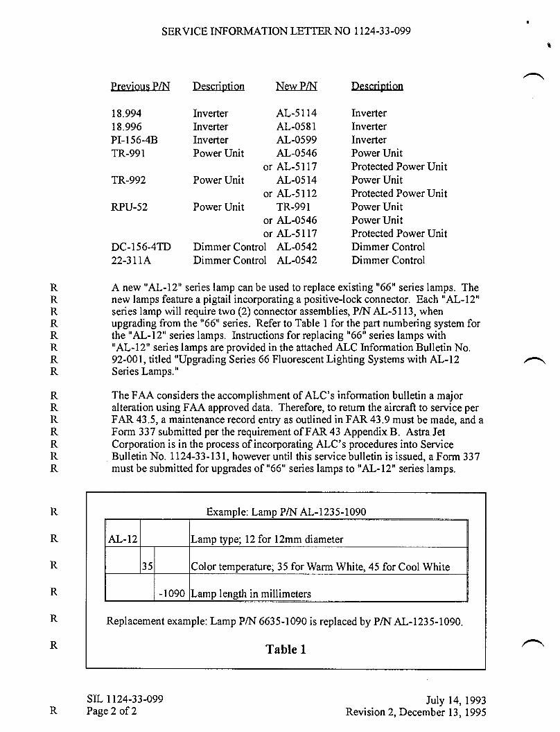
SERVICE INFORMATION LETTER NO 1124.33-099
Previous PA{ Description New PAI T\escription
18.994 Inverter AL-51l4 Inverter18.996 Inverter AL-0581 InverterPI-156-4B Inverter AL-0599 InverterTR-991 Power Unit AL-0546 Power Unit
or AL-5117 Protected Power UnitTR-992 PowerUnit AL-0514 PowerUnit
or AL-5112 Protected PowerUnitRPU-52 PowerUnit TR-991 PowerUnit
or AL-0546 Power Unitor AL-5117 Protected Power Unit
DC-156-4TD Dimmer Control AL-0542 Dimmer Control22-3ILA Dimmer Control AL-0542 Dimmer Control
R A new "AL-L?' series lamp can be used to replace existing "66" series lamps. TheR new lamps feature a pigtail incorporating a positive-lock connector. Each "AL-12"R series lamp will require rwo (2) connector assemblies, PA{ AL-5113, whenR upgrading from the "66" series. Refer to Table I for the part numbering system forR the "AL-12" series lamps. Instructions for replacing "66" series lamps withR "AL-lzu series lamps are provided in the attached ALC Information Bulletin No.R 92-001, titled "Upgrading Series 66 Fluorescent Lighting Systems with AL-I2R Series Lamps."
R The FAA considers the accomplishment of ALC's information bulletin a majorR alteration using FAA approved data. Therefore, to return the aircraft to service perR FAR 43.5, a maintenance record entry as outlined in FAR 43.9 must be made, and a
R Form 337 submiued per the requirement of FAR 43 Appendix B. Astra JetR Corporation is in the process of incorporating ALC's procedures into ServiceR Bulletin No. 1124-33-131, however until this service bulletin is issued, a Form 337R must be submitted for upgrades of "66" series lamps to "AL-12" series lamps.
mDle: Lam
AL-12 Lamp type; 12 for l2mm diameter
35 Color temperature; 35 for Warm White, 45 for Cool White
-1090 Lamp length in millimeters
Examnle: Lamo PA{ AL-1235-1090
Replacement example: Lamp PA{ 6635-1090 is replaced by PA{ AL-1235-1090.
Table I
R
R
RsIL 1124-33-099Page2 of 2
July 14, 1993Revision 2, December 13, 1995
lnformation Bulletin No. 92-001
INFORMATION BULLETIN
FOR
UPGRADING SERIES 66 FLUORESCENT LIGHTING SYSTEMS
WITH
AL-l2 SERIES LAMPS
Manufactured BY:
AEROSPACE LIGHTING CORPORATION101-8 Colin Drive
Holbrook, NY 11741
Phone (516) 563-6400Fax (516) 563-8781
REVISION A RELEASE 6/21195
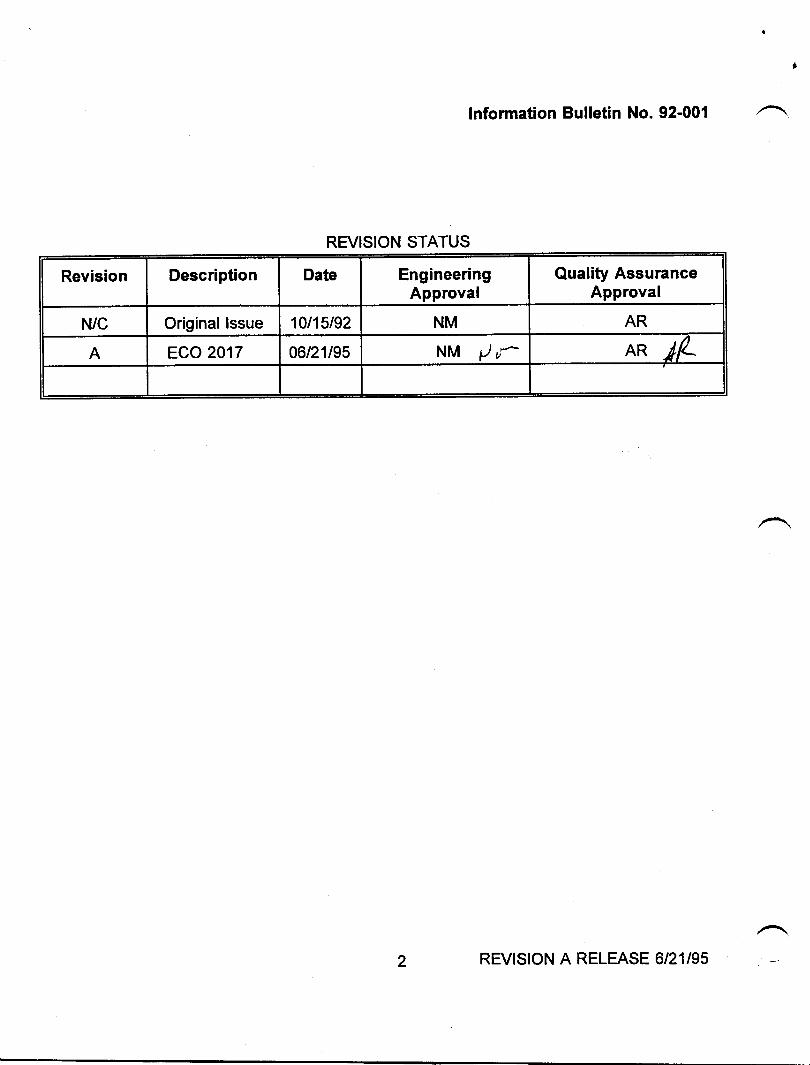
lnformation Bulletin No. 92-001
REVISION STATUS
Revision Description Date EngineeringApproval
Quality AssuranceApproval
N/C Original lssue 10t15t92 NM AR
A ECO 2017 06t21195 NM /,r AR ^dA
2 REVISION A RELEASE 6/21195
PARAGRAPH
1.02.03.04.04.14.24.34.44.55.06.0
TABLE
1
FIGURE
TITLE
IntroductionApplicabilityToolsRemoval replacement proceduresLamp Connection (31.85.1A) Removal ProceduresLamp Connector (AL-S1 13) Installation ProceduresFluorescent Lamp (P/N 66XX-XXX) RemovalFluorescent Lamp (P/N AL12XX-XXX) lnstallationConnection Of AL "12" Series Lamp to AL-5113 ConnectorSystem lnspection and CheckoutReturning The Aircraft to Service
LIST OF TABLES
TITLE
List of Tools
LIST OF FIGURES
TITLE
Removal of Locking Ring and Lamp Connector BodyLamp Connector (31.85.1A) RemovalLamp Connector (AL-S113) AssemblyLamp PlacementLamp Installation
Information Bulletin No. 92-001
TABLE OF CONTENTS
PAGE
PAGE
44455677B
88
1
2345
PAGE
56778
NOTEThe technical data contained in this Information Bulletin has been approved by the New York
Certification Office of the Federal Aviation Administration.
3 REVISION A RELEASE 6/21l95
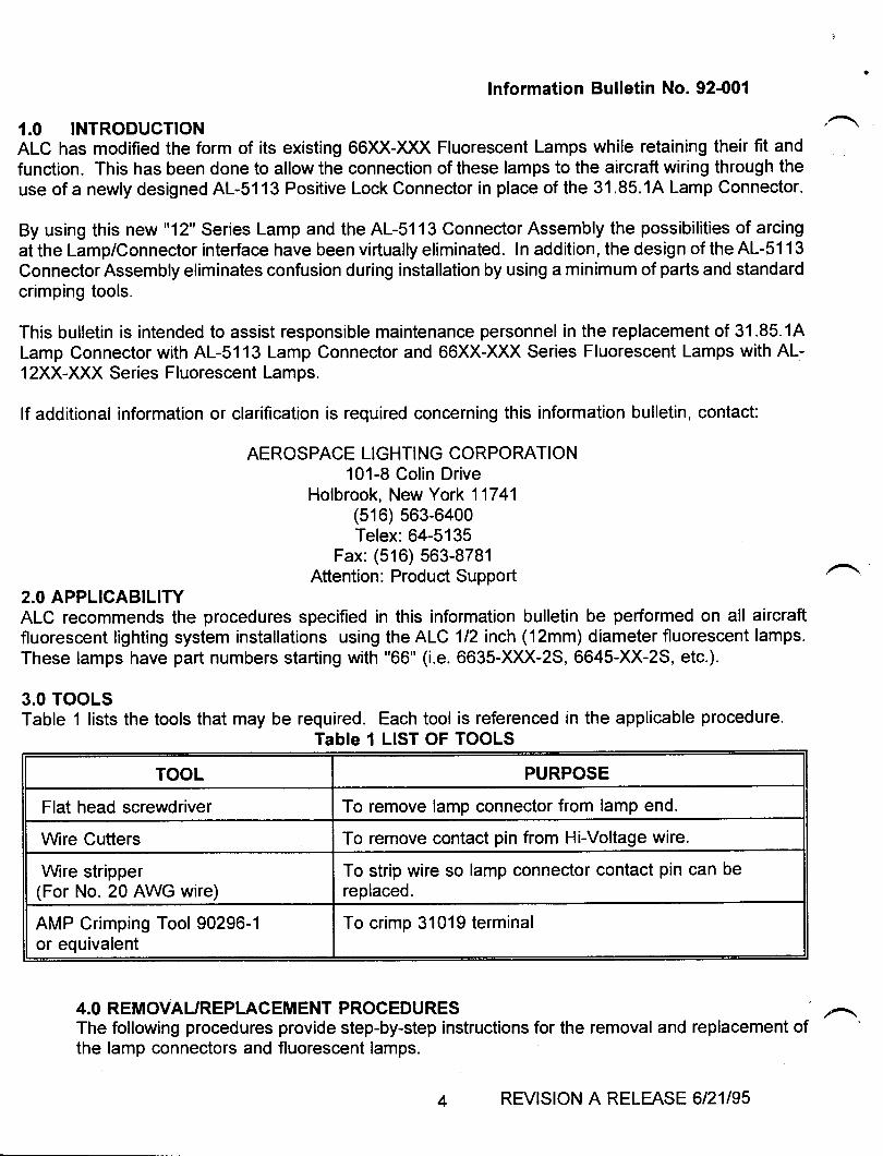
lnformation Bulletin No. 92-001
1.0 INTRODUCTIONALC has modified the form of its existing 66XX-XXX Fluorescent Lamps while retaining their fit andfunction. This has been done to allow the connection of these lamps to the aircraft wiring through theuse of a newly designed AL-51 13 Positive Lock Connector in place of the 31 .85.1A Lamp Connector.
By using this new "12" Series Lamp and the AL-51 13 Connector Assembly the possibilities of arcingat the Lamp/Connector interface have been virtually eliminated. In addition, the design of the AL-s1 13
Connector Assembly eliminates confusion during installation by using a minimum of parts and standardcrimping tools.
This bulletin is intended to assist responsible maintenance personnel in the replacement of 31.85.1ALamp Connector with AL-5113 Lamp Connector and 66XX-XXX Series Fluorescent Lamps with AL-12XX-XXX Series Fluorescent Lamps.
lf additional information or clarification is required concerning this lnformation bulletin, contact:
AEROSPACE LIGHTING CORPORATION101-8 Colin Drive
Holbrook, New York 11741(516) 563-6400Telex:64-5135
Fax: (516) 563-8781Attention: Product Support
2.0 APPLICABILITYALC recommends the procedures specified in this information bulletin be performed on all aircraftfluorescent tighting system installations using the ALC l12inch (12mm) diameter fluorescent lamps.These lamps have part numbers starting with "66" (i.e. 6635-XXX-2S, 6645-XX-2S, etc.).
3.0 TOOLSTable 1 lists the tools that may be required. Each tool is referenced in the applicable procedure.
Table 1 LIST OF TOOLS
TOOL PURPOSE
Flat head screwdriver To remove lamp connector from lamp end.
Wire Cutters To remove contact pin from Hi-Voltage wire.
Wire stripper(For No. 20 AWG wire)
To strip wire so lamp connector contact pin can bereplaced.
AMP Crimping Tool 90296-1or equivalent
To crimp 31019 terminal
4.0 REMOVAUREPLACEMENT PROCEDURESThe following procedures provide step-by-step instructions for the removal and replacement ofthe lamp connectors and fluorescent lamps.
REVISION A RELEASE 6/21l95
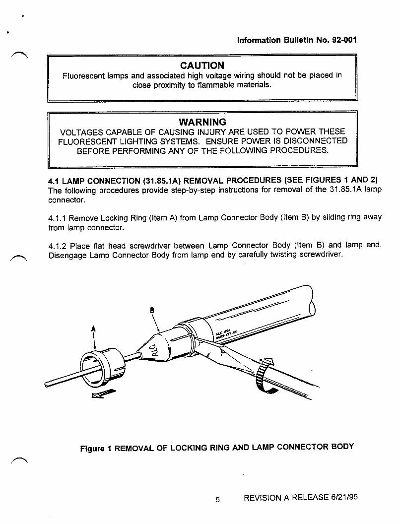
lnformation Bulletin No. 92-001
CAUTIONFluorescent lamps and associated high voltage wiring should not be placed in
close proximity to flammable materials.
WARNINGVOLTAGES CAPABLE OF CAUSING INJURY ARE USED TO POWER THESEFLUORESCENT LIGHTING SYSTEMS. ENSURE POWER IS DISCONNECTED
BEFORE PERFORMING ANY OF THE FOLLOWING PROCEDURES.
4.1 LAMP CONNECTTON (31.8s.1A) REMOVAL PROCEDURES (SEE FIGURES 1 AND 2)
The following procedures provide step-by-step instructions for removal of the 31.85.1A lamp
connector.
4.1.1 Remove Locking Ring (ltem A) from Lamp Connector Body (ltem B) by sliding ring away
from lamp connector.
4.1.2 Place flat head screwdriver between Lamp Connector Body (ltem B) and lamp end.
Disengage Lamp Connector Body from lamp end by carefully twisting screwdriver.
Figure 1 REMOVAL OF LOCKING RING AND LAMP CONNECTOR BODY
5 REVISION A RELEASE 6/21195
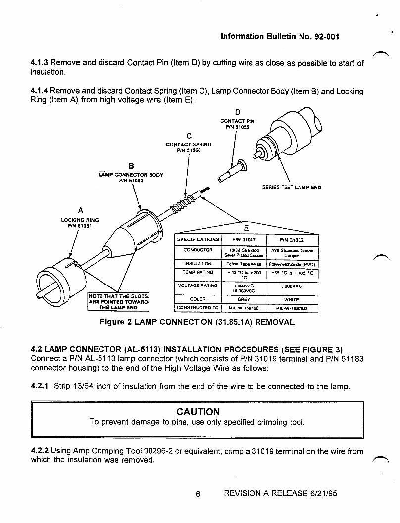
lnformation Bulletin No. 92-001
4.1.3 Remove and discard Contact Pin (ltem D) by cutting wire as close as possible to start ofinsulation.
4.1.4 Remove and discard Contact Spring (ltem C), Lamp Connector Body (ltem B) and LockingRing (ltem A) from high voltage wire (ltem E).
DcoilTAcT P||l
P,N 51059
Bf,rlnp conrecroR Booy
P,N 6t052
4.2 L.AMP CONNECTOR (AL-5113) TNSTALLATTON PROCEDURES (SEE FTGURE 3)Connect a P/N AL-51 13 lamp connector (which consists of P/N 31019 terminal and P/N 61 183connector housing) to the end of the High Voltage \Mre as follows:
4.2.1 Strip 13/64 inch of insulation from the end of the wire to be connected to the lamp.
CAUTIONTo prevent damage to pins, use only specified crimping tool.
4.2.2 Using Amp Crimping Tool 90296-2 or equivalent, crimp a 31019 terminal on the wire fromwhich the insulation was removed.
SERIES.66- LAT'P €NO
sP€crFrcATtoHs I PrN 310{7
-55'C l(t i r05 'C
VOLTAGE RATING
CONSTFUCTEO TO I r.[.w.r6!7!E
Figure 2 I-AMP CONNECTION (31.85.1A) REMOVAL
REVISION A RELEASE 6/21195
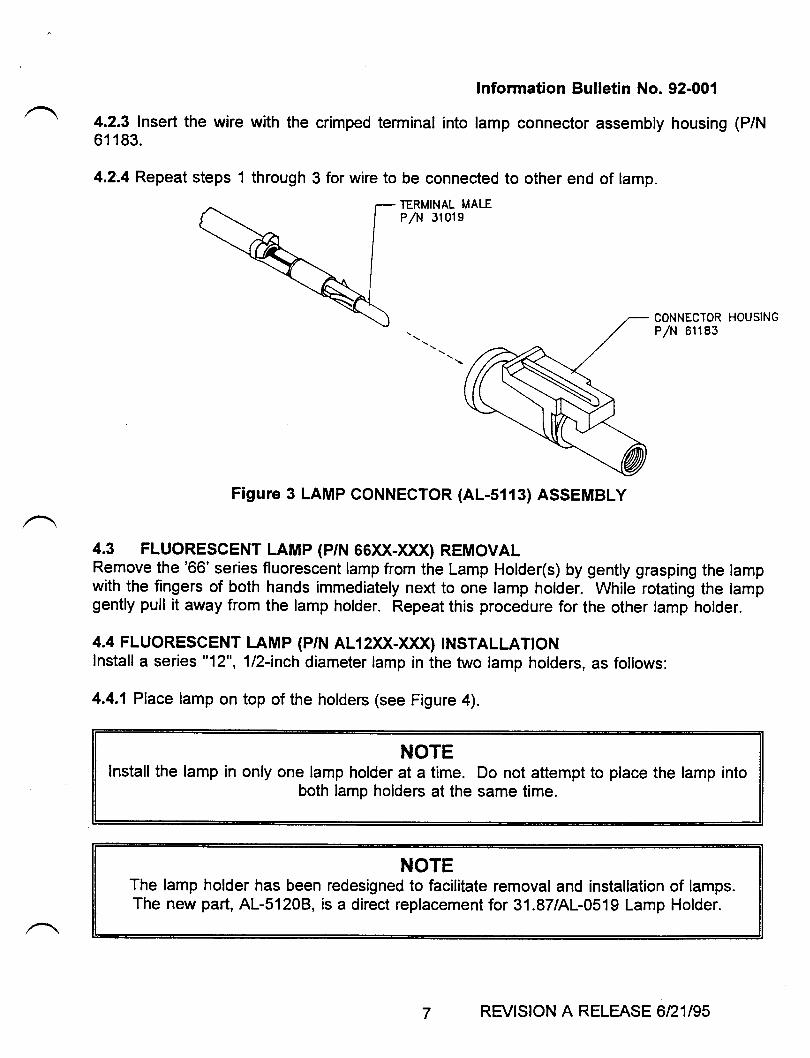
Information Bulletin No. 92-001
4.2.3 Insert the wire with the crimped terminal into lamp connector assembly housing (P/N61 183.
4.2.4 Repeat steps 1 through 3 for wire to be connected to other end of lamp.
TERMINAL MALEP/N 3101s
CONNECTOR HOUSINGP/N 61183
Figure 3 LAMP CONNECTOR (AL-5113) ASSEMBLY
4.3 FLUORESCENT LAMP (p/N 66)q-XXX) REMOVALRemove the '66' series fluorescent lamp from the Lamp Holder(s) by gently grasping the lampwith the fingers of both hands immediately next to one lamp holder. While rotating the lampgently pull it away from the lamp holder. Repeat this procedure for the other lamp holder.
4.4 FLUORESGENT LAMP (p/N AL12XX-XXX) TNSTALLATTONfnstafl a series "12",1|z-anch diameter lamp in the two lamp holders, as follows:
4.4.1 Place lamp on top of the holders (see Figure 4).
NOTEInstall the lamp in only one lamp holder at a time. Do not attempt to place the lamp into
both lamp holders at the same time.
NOTEThe lamp holder has been redesigned to facilitate removal and installation of lamps.The new part, AL-5120B., is a direct replacement for 31.87/AL-0519 Lamp Holder.
7 REVISION A RELEASE 6/21195
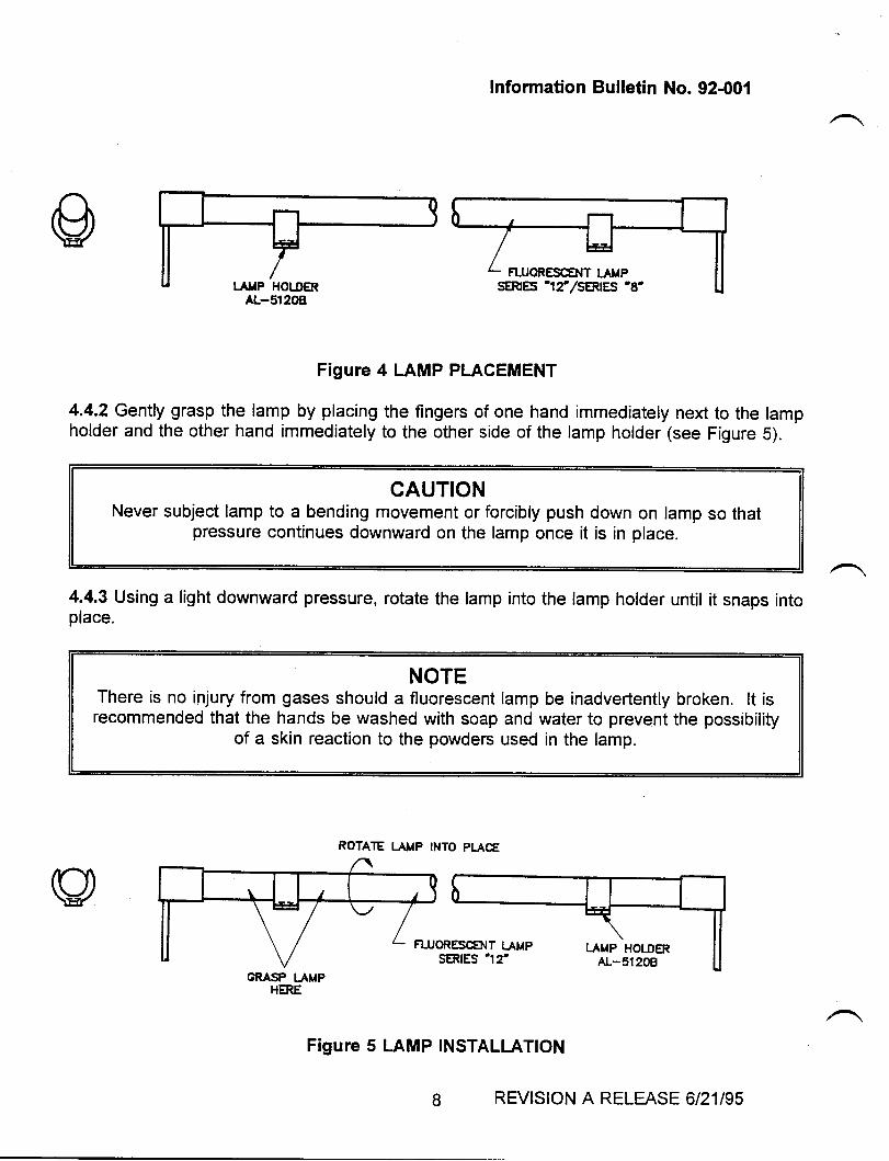
Information Bulletin No. 92-001
Figure 4 LAMP PLACEMENT
4.4.2 Gently grasp the lamp by placing the fingers of one hand immediately next to the lampholder and the other hand immediately to the other side of the lamp holder (see Figure 5).
CAUTIONNever subject lamp to a bending movement or forcibly push down on lamp so that
pressure continues downward on the lamp once it is in place.
4.4.3 Using a light downward pressure, rotate the lamp into the lamp holder until it snaps intoplace.
NOTEThere is no injury from gases should a fluorescent lamp be inadvertently broken. lt isrecommended that the hands be washed with soap and water to prevent the possibility
of a skin reaction to the powders used in the lamp.
ROTATE I.ATIP INTO PLACE
Figure 5 LAMP INSTALLATION
CRASP IJMPHERE
FLUORESCENT LAMPSERIES '12',/SERtES'8'
FLUORESCENT I.AMPSERIES '12'
REVISION A RELEASE 6/21195

4.2.3lnsert the wire with the crimped terminat ,rrr ,::;::::,:::::J;:::::, ,rr-61 183.
4.2.4 Repeat steps 1 through 3 for wire to be connected to other end of lamp.
TERMINAL MALEP/N 31019
CONNECTOR HOUSINGP/N 61183
Figure 3 LAMP CONNECTOR (AL-5113) ASSEMBLY
4.3 FLUORESCENT LAMP (p/N 66)U-XXX) REMOVALRemove the '66' series fluorescent lamp from the Lamp Holder(s) by gently grasping the lampwith the fingers of both hands immediately next to one lamp holder. While rotating the lampgently pull it away from the lamp holder. Repeat this procedure for the other lamp holder.
4.4 FLUORESCENT LAMP (p/N AL12XX-)qX) TNSTALLATTONInstall a series "12", 112-inch diameter lamp in the two lamp holders, as fotlows:
4.4.1 Place lamp on top of the holders (see Figure 4).
NOTEInstall the lamp in only one lamp holder at a time. Do not attempt to place the lamp into
both lamp holders at the same time.
NOTEThe lamp holder has been redesigned to facilitate removal and installation of lamps.The new part, AL-51208, is a direct replacement for 31.87/AL-0519 Lamp Holder.
7 REVISION A RELEASE 6/21195
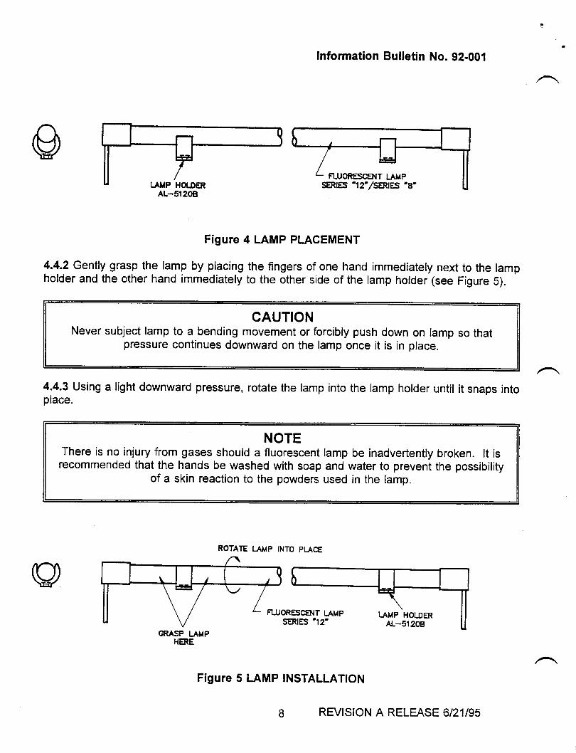
Information Bulletin No. 92-001
Figure 4 LAMP PLACEMENT
4.4.2 Gently grasp the lamp by placing the fingers of one hand immediately next to the lampholder and the other hand immediately to the other side of the lamp holder (see Figure 5).
CAUTIONNever subject lamp to a bending movement or forcibly push down on lamp so that
pressure continues downward on the lamp once it is in place.
4.4.3 Using a light downward pressure, rotate the lamp into the lamp holder until it snaps intoplace.
NOTEThere is no injury from gases should a fluorescent lamp be inadvertently broken. lt isrecommended that the hands be washed with soap and water to prevent the possibility
of a skin reaction to the powders used in the lamp.
ROTATE LAMP INTO PI.ACE
Figure 5 LAMP INSTALLATION
GRAS? LAMPHERE
REVISION A RELEASE 6/21195
lnformation Bulletin No. 92-001
4.5 CONNECTTON OF AL ''12' SERIES LAMP TO AL-5113 CONNECTORConnect the pigtail of each lamp end to the appropriate AL-5113 connector by inserting andpushing the AL-5113 into the blue connector at the end of the large pigtail until the locking armof the AL-5113 snaps into place over the ridge at the end of the connector on the lamp pigtail.
5.0 SYSTEM INSPECTION AND CHECKOUTVisually check all wire connections and lamp mountings for security. Apply system power andobserve illumination of lamps. lf any malfunction, recheck wiring. lf problems persist, contactAerospace Lighting Corporation Product Support at (516) 563-6400.
6.0 RETURNING THE AIRCRAFT TO SERVICEThe FAA considers the accomplishment of this bulletin a major alteration using FAA approveddata. Therefore, to return the aircraft to service per FAR 43.5, a maintenance record entry asoutlined in FAR 43.9 must be made, and a Form 337 submitted per the requirement of FAR 43Appendix B.
REVISION A RELEASE 6/21195
'a
^:SERVICE PUBLICATIONS
revision noticesrl, No. LL24-34-0L2Revision No. ISUBiIECT: COAXIAL CABLE CLAMPING
April 5, 1985
EFFEcrrvrrY: lloDEL LL24/LL24A !{EsrI{rND, all seriaL numbersthrough S,/N 435
A. REASON
To eliminate Avionics systems antennaby inproper coaxiaL cabLe bend rad.iusdamage.
related probl.ems causedandr/or inner core
NOTE
-
Location of defective areamay onJ,y be properly deter-mined by use of the Time DomainReflectometry (TDR) tester.Visual- inspection nay be usedto determine improper coaxiaLcable bend radius and strain
,/ reLiefr €ts well- as improperlyassembled connectors.
. DESCRIPTION
(1) Connect the Time Domain Reflectometry tester to one endof the coaxial cabre to be tested. Determine the proper"terminatortr that will have the correct rrload impedance"for that specific type of coaxiar cabr.e. connecl thiEterminator at the opposite end of the sane cable.
sIL 1L24-34-012Page I of I
NTWIA'TT|,,,L rc.utm..,'n!trryrt
llutSrorlnY oF 13RA€! atRcRAFr lxouSTtttg. rrD8EN OUnTON ArnpORT. tSlA:L
ft,
TilT{SERY'CEINFORMATION LETTER
SIL NO. LI24-34-OL2 february 8, 1985
SUBJECT: COAXIAL CABLE CLAMPING
EFFECTIVTTY: MODEL II24/LL24A WESTWIND, all serial numbersthrough S,/N 435
A. PEASON
To eliminate Avionics systems antenna rerated problemscaused by improper coaxial cable bend radius aid,/or innercore damage.
NOTE
Location of defective areamay only be properly deter-mined by use of Time DomainReflectometry.
Visual inspection may beused to determine impropercoaxial cable bend radiusand strain rel_ief r €rS wellas improperly assembledconnectors. Visual inspec-tion of suspected crushedareas requires access toentire cable run, and willprobably prove ineffective.
B. DESCRIPTION
(1) Terminate with proper load impedance the end of coaxialcable suspected of damage opposite that to which TDR isconnected.
@ lI I s:rms p*n* t!yf;;., *.,, *SIL IT24-34-OI2Page 1 of 3
SUBSIDIARY OF ISRAEL AIRCRAFT INDUSTRIES, LTDBEN GURION AIRPORT, ISRAEL
/
SERVICE INFORMATION LETTER 1124-34-OI2
(2) Determine position of fault(s) as determined by TDRmeasurement and wave-length or system operationalfrequency being inspected.
(3) Gain access to suspect area as required.(4) Inspect and repair damaged areas:
(a) Cut tywraps that may be overtightenedr or arecreating severe bend angles to permit strainre lief.
(b) Should coaxial cable length not be adequateto prevent strain at connectors, install 90oadapters of proper UGrlMS type.
(c) Inspect for crushed coax under DG cable clamps.Cable should be free to move within clamps.
(5) Perform TDR test again.
(a) Should fault(s) not appear, replace DG clampswith proper size. See Table 1 following.(1) If needed, secure cable bundles with
appropriate length of Tywrap, Do notover tighten and crimp coaxial cables.
(b) Should fault sti1l exist, repair by replacingdefective cable segment using proper UG/MSmale/female splices to fit system coaxial cableunder test.
(c) Should multiple serious faults exist, replaceentire coaxial cable run, using as cautionsthe inspections outlined under paragraph 4above.
(6) once the TDR test has determined the coaxial cableand associated connectors are acceptable, you maychoose to test the system antenna and antennabonding.
(a) Disconnect dummy termination (paragraph Iabove).
SIL LL24-34-OI2Page 2 of 3
February 8, I9B5
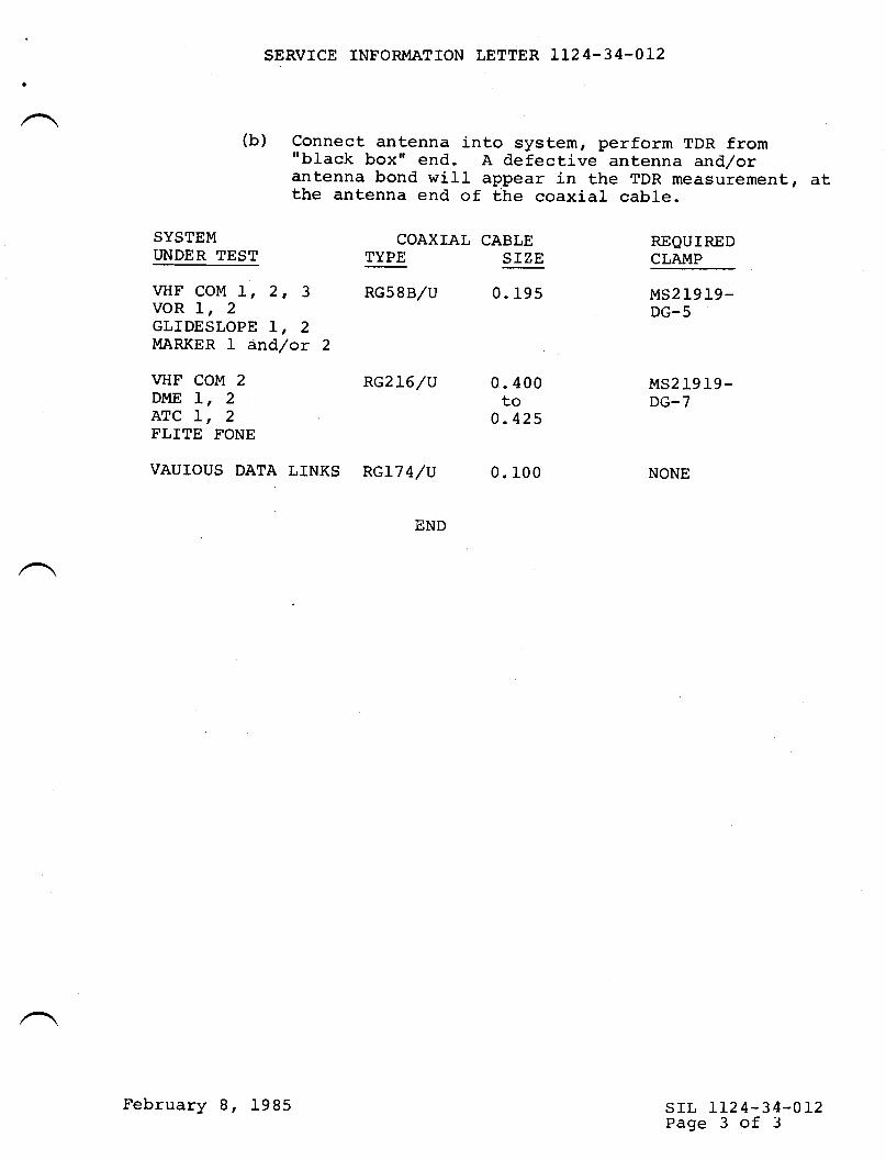
SERVICE INFORMATION LETTER 1].2 4-34-OL2
(b) Connect antenna into system, perform TDR from"black box" end. A defective antenna and/orantenna bond will appear in the TDR measurement, dtthe antenna end of the coaxial cable.
SYSTEIVI COAXIAL CABLE REQUIREDT'NDER TEST TYPE SIZE CLAMP
vHF COM 1, 2, 3 RGsgB/V 0.195 MS21919_VOR 1, 2 DG-5GLIDESLOPE L, 2MARKER 1 dnd/or 2
vHF COM 2 Rc2L6/u 0.400 MS21919_DI{E l, , Eo DG-7ATC L, 2 0.425FLITE FONE
vAurous DATA LINKS RGL7A/V 0. lO0 NONE
SIL LL24.34-OT2Page 3 of 3
February 8, 1985
IWTSERY'CEINFORMATION LETTER
A.
B.
D.
srl, No. 1124-34-02L February L9, 1985
SUBJECT: INSTALLATION OF CHAFE-GUARD MATERIAL ON WIRE BUNDLESAT STATION 269 NEAR EMERGENCY GYRO POWER SUPPLY.
EFFECTIVITY: LL24/LL24A - A11 serial numbers.
c.
REASON:
There exists the possibility of damaging wire bundles locatedimmediately aft of the PS 823 Bnergency Gyro Power Supplyrack during routine removal or installation of the powersupply.
REFERENCES:
None
PUBLICATIONS AF'FECTED :
None
DESCRTPTTON (OR TNSTRUCTTONS) (Snn FTGURE 1)
1. Gain access to the PS 823 Emergency Gyro Power Supplyinstalled near station 269 (Ieft-hand side).
2. Remove power supply from rack.
3. Determine presence of wire bundles located immediately aftof the rack installation. Check bundles for prior damage.
4. Select a material available for installation as aprotective covering such as:
February f9, 1985 / srr, LL24-34-02LPage 1 of 2
SUBSIDIARY OF ISRAEL AIRCRAFT INDUSTRIES, LTD
BEN GURION AIRPORT, ISRAEL
@ lill vrxsp*** !,#;.,*,*
SERVTCE INF'ORMATION LETTER NO. LL24.34-O2I
a. Spiral wrap of proper core size.
b. Viny1 tubing of I/8" wall thickness or greater.Install using standard lacing or tie-wrap method".
,,,,
5. Reinstall PS 823 Power Supply, reinstall panelsr/bulkheadspreviously removed and return aircraft to service.
END
srr, IL24-34-021Page 2 of 2
February l-9. L9g5
';t+ SERVICE PUBLICATIONS
revision notice
,^
f su., no. Ll24-34-03LA April 29, 1985Revision No. I
SUB.IECT: PILOT AI{D CO-PTLOT AIiINUNCIATOR PAIIEL CABLE BTNDLECHAFING/SHORTING
EFFECTMTY: MODEL LL24|LL24A WESTWINDS , all serial nr:mbers.
A. REASON
To eliminate, chafing of annunciator wire butdles againstan air duct.
B. REFERENCE
Not applicable.
C. PUBTICATIONS AFFECTED
Not applicabl-e.
D. DESCRIPTION
Remove glare shieLd. Locate the plastic wire bundleclamps that contain the annunciator wiring at the upper'outboard side of each set of autopiloL annunciator.Remove the screws holding these clamps to the mor:ntingpost. Remove the clamps, and invert them so the wirebturdle is relocated below the morrnting post to clear themetal air duct clamps.
Reinsta1J. glare shield'
-\
J4
sB LL24-34-03rAPage I of I/
@lfrlwxrm!***SUSSIDIAFY OF ISRAEL AIRCRAFT INOUSTFTI€S. LIO
8EN GUNION AIRPORI. ISFIA€L
.^
TWTSERY'CEINFORMATION LETTER
srl, No. LL24-'34-031_ March 13, 1985
SUBJECT: PILOT AttD CO-PILOT AI{NUNCIATOR PAlilEL CABLE BUNDLECHAFTNG/SHORTTNG
EFFECTIVITY: MODEL LL24/LL24A WESTWINDS, all serial numbers.
A. REASON
To eliminate chafing of annunciator wire bundles againstan air duct.
B. REFERENCE
Not applicable.
PUBLICATIONS AFFECTED
Not applicable.
DESCRIPTION
Remove both annunciator panels. Locate the two plasticannunciator wire-bundle ci.amps near the top of each panel.Remove the mounting-post scre$/s holding these clamps.Reverse their position to move the wire bundle away fromthe air duct and re-install mounting post screws. Re-installannunciator paneJ-s.
c.
D.
/
@lilsrmpx*!l*;,*'*SUBSIDIARY OF ISRAEL AIRCRAFT INDUSTRIES, LTD
BEN GURION AIRPORT, ISRAEL
srl, 1124-34-031Page I of I
TWTSERY'CEINFORMATION LETTER
srl, No. LL24-34-036 March 20, 1985
SUBJECT: AOA SYSTEM - COMPONENT REPLACEIT{ENT
EFFECTMTY: MODEL L124A WESTWIND, all serial numbers.
A, REASON
, To provide a procedure to replace the AOA indicator,Teledyne P/N sLz9944 with P/N sLz9944A, should replacementbecome necessary.
B. REFERENCES
Teledyne Avionics Publication SN507, revision B, GroundTest and Adjustment Procedures For The Angle of Attack
C. PUBLICE,TIONS AFFECTED
Teledyne Avionics Publication SN507, revision B, item 3.2.
NOTE
Publication is' affected only whenSLZ9944 indicatoris replaced bySLZ9944A indicator.
D. DESCRIPTION
(f) Remove and replace AOA indicator inChapter 34-10-07 of the LI24/LI24A
(21 Gain access to transmitter locatedfuselage at station 86.90. Remove. as required.
accordance withMaintenance Manual.
on right side ofupholstery or panels
/
@lfllwww*!lx?**,,nSUBSIDIARY OF ISRAEL AIRCRAFT INDUSTRIES, LTD
BEN GURION AIRPORT, ISRAEL
srl, Lt24-34-036Page 1 of 2
SERVICE INFORMATION LETTER NO. LL24-34-036
(3) Record the setting of the transmitter to the mountingplate in degrees. Reference Chapter 34-10-07 of theIL24/Ll24A Maintenance Manual, Figure 402.
(4) Accomplish the ground check procedure in accordancewith Chapter 34-10-07 of the IL24/LI24A t'laintenanceManual.
(5) Change the transmitter mounting plate adjustment by aminus 2.1 degrees (i.e., rotate top of probe housingaft) from the setting recorded in Step D.3. Recordthe new setting.
Example: If the probe calibration was 14.8 degreesfor the SLZ9944 indicator, adjust themounting plate to L2.7 degrees for theSLZ9944A indicator.
(6) Torque all hardware to 30 inch-pounds.
(71 Recheck new setting.(8) Install upholstery or panels as required.
srl, 1124-34-036Page 2 of 2
March 20, I9g5
Til?{SERY'CEINFORMATION LETTER
srr, No. LL24-34-040 April 2, 1985
srl, LL24-34-040Page I of 4
SUBJECT: RADAR STABILIZATION IMPROVEMENTS
EFFECTMTY: MODEL LL24/LI24A WESTWIND, all serial numbers.
A. REASON
To provide instructions to properly level and adjust theradar antenna and stabilization system.
Performance of these procedures will elimj-nate excessiveground clutter displays, especially during turns and climb.
B. REFERENCES
LL24/LI24A Maintenance Manual, Chapter 34-40-01, 34-40-02,34-40-03 t ot 34-40-04 as determined by radar systeminstalled.LL24/LI24A Service Information Letter No. LL24-22-038.LI24/LI24A Service Informat,ion Letter No. 1124-22-039.
C. PUBLICATIONS AFFECTED
IL24/LL24A Maintenance Manual, Chapter 34-40-01, 34-40-02,34-40-03, or 34-40-04 as determined by radar systeminstalled-
D. INSTRUCTIONS
(t) Ensure aircraft and vertical gyro are level. ReferenceSIL No. 1124-22-038 for proper procedure.
(21 Remove radome; and gain access to #1 vertical gyro.
(3) Disable transmitter and antenna scan as appropriatefor your system. Turn radar system ON.
/
@ II I wm* w* t,!^!!s;., *n,, *SUBSIDIARY OF ISRAEL AIRCRAFT INDUSTRIES, LTD
BEN GURION AIRPORT, ISRAEL
SERVICE INFORMATION LETTER NO. IL24.34-O4O
(4) Position antenna plate to Oo azimuth by referenceto azimuth index. Secure antenna plate as requiredto prevent substantial movement. DO NOT force anyvertical movement of antenna dish.
(5) Set TILT control to Oo. Using a calibrated, adjust-able level and a rigid straightedge, perform thefollowing measurements to within + L/40.
NOTE
Use of a standard"bubble" IeveI willnot permit properaccuracy.
(a) Measure across top of radar dishr or thehorizontal feeder bar, to establish a roll leve1.Reference aircraft level points. If an errorexists between antenna and aircraft, proceed toStep 6.
(b) Measure the yaw axis error by drawing a linebetween a plumb bob at the tail skid and thecenter axis of the nose gear strut extendedbeyond radar antenna. Locate the center of theantenna dish, use a 90o angle to extend thisline at least 18", and measure between plumb lineand antenna centerline extension. ff an errorexists, proceed to Step 6.
(c) Measure the pitch leve1 at the antenna pedestalmounting brackets. Reference exactly 90o toaircraft pitch level points. If an error exists,proceed to Step 6.
(6) should any angular error exist from steps 3, 4, or 5above, remove antenna from airframe mount. Discardany existing shim washers.
(a) To remove roll errors. remove antenna basemounting brackets, and elongate the mountingbolt holes (use an arc pattern based on oppositecorner mounting hole center) slightly to permitrotation of mounting brackets on nose bulkhead.
(b) To remove yar^r errors, reinstarl mounting brackets,with shims for both mounting bolts (RHS or LHS asrequired) of identical thickness to correctantenna centerline error.
srl, 1124-34-040Page 2 of 4
April 2, 1985
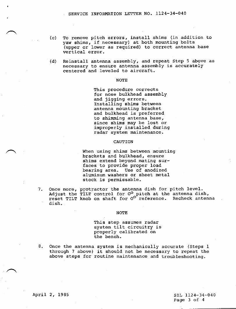
SERVICE INFORMATION LETTER NO. LL24-34-O4O
(c) To remove pitch errors, install shims (in addition toyaw shims, if necessary) at both mounting bolts(upper or lower as required) to correct antenna basevertical error.
(d) Reinstall antenna assembly, and repeat Step 5 above asnecessary to ensure antenna assembly is accuratelycentered and leveled to aircraft.
NOTE
This procedure correctsfor nose bulkhead assemblyand jigging errors.Installing shims betweenantenna mounting bracketand bulkhead is preferredto shimming antenna base,since shims may be lost orimproperly installed duringradar system maintenance.
CAUTION
When using shims between mountingbrackets and bulkhead, ensureshims extend beyond mating sur-faces to provide proper loadbearing area. Use of anodizedaluminum waghers or sheet metalstock is permissable.
7. Once morer pfotractor the antenna dish for pitch level.Adjust the T1LT control for Oo^pitch at the antenna dish,reset TILT knob on shaft for Oe reference. Recheck antennadish.
NOTE
This step assumes radarsystem t,i1L circuitry isproperly calibrated onthe bench.
8. Once the antenna system is mechanically accurate (Steps 1through 7 above) it should not be necessary to repeat theabove steps for routine maintenance and troubleshooting.
srl, IL24-34-040Page 3 of 4
April 2, 1985
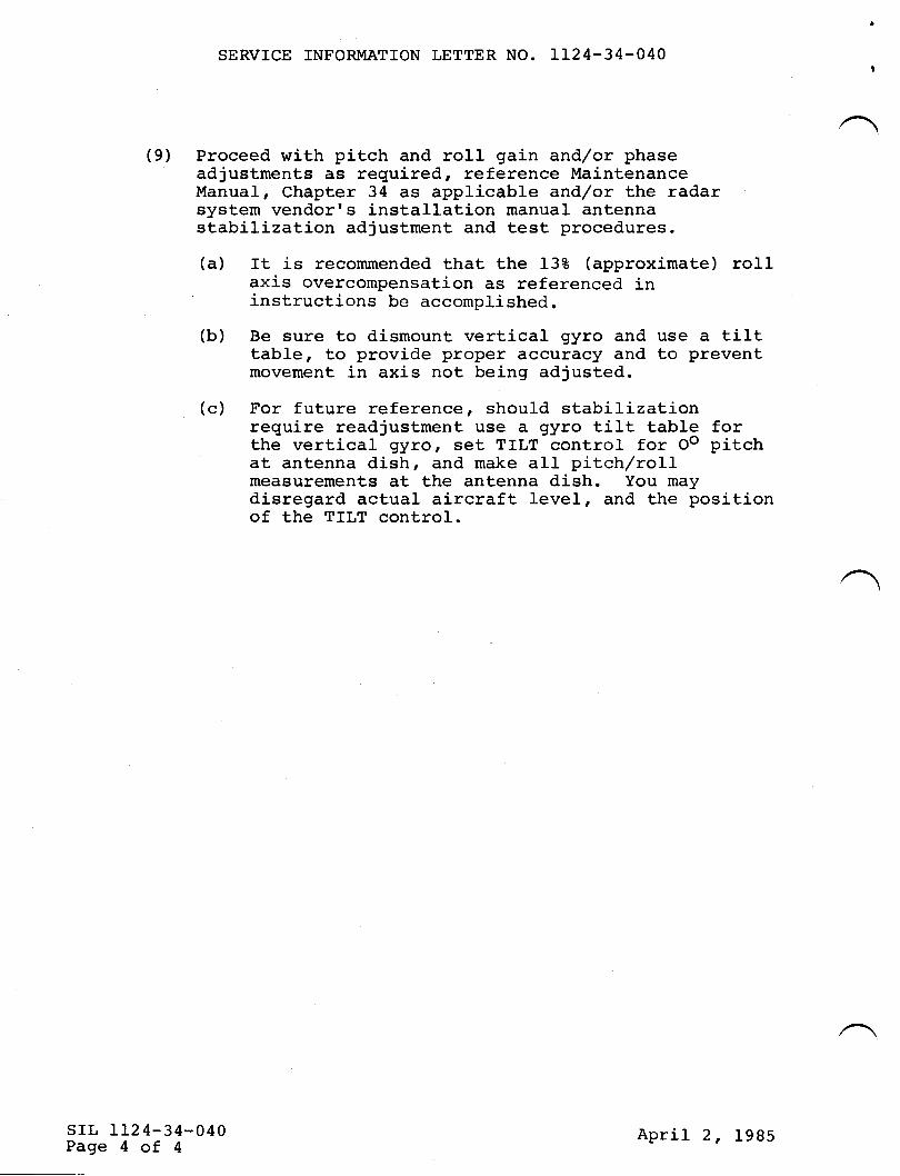
SERVICE INFORMATION LETTER NO. IT24-34.040
(9) Proceed with pitch and roII gain and,/or phaseadjustments as required, reference MaintenanceManual, Chapter 34 as applicable and,/or the radarsystem vendorr s insta]lation manual antennastabilization adjustment and test procedures.
(a) It is recommended that the 138 (approximate) ro11axis overcompensation as referenced ininstructions be accomplished.
(b) Be sure to dismount vertical gyro and use a tilttab1e, to provide proper accuracy and to preventmovement in axis not being adjusted.
(c) For future reference, should stabilizationrequire readjustment use a gyro tilt table forthe vertical gyro, set TILT control for Oo pitchat antenna dish, and make all pitch/roLlmeasurements at the antenna dish. You maydisregard actual aircraft level, and the positionof the TILT control.
srr, II24-34-040Page 4 of 4
April 2, 1985
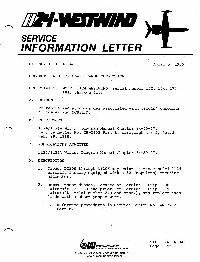
TWlSERY'CEINFORMATION LETTER
srr, No. t124-34-046
SUBJECT: NCS3l/A SLANT RANGE CORRECTION
April 5, 1985
EFFECTIVITY: MODEL LL24 WESTWIND, serial number L52, L54t I74,181, through 4L0.
A. REASON
To remove isolation d.iodes associated with pilotsr encodingaltimeter and NCS3I/A.
B. REFERSNCES
IL24/L124e wiring Diagram Manual Chapter 34-50-07.Service Letter No. Wfi-2452 Part B, paragraph 4 a 5, datedFeb. 28, 1980.
C. PUBLICATIONS AFFECTED
IL24/LI24A Wiring Diagram ir{anual Chapter 34-50-07.
D. DESCRIPTION
1. Oiodes DI200 through DI2O6 may exist in those Model Ll-24aircraft factory equipped with a #Z (copilots) encodingaltimeter.
2. Remove these diodes, located at Terminal Strip T-30(aircraft S/N 239 and prior) or Terminal Strip T-I9(aircraft serial number 240 and subs.), and replace eachdiode with a short jumper wire.
€r. Reference procedures in Service Letter No. |uflul-2452Part B.
/
@III sr**nrw*tffin*.,,*SUBSIDIARY OF ISRAEL AIRCRAFT INDUSTRIES, LTD.
BEN GURION AIRPORT, ISRAEL
srl, 1124-34-046Page I of I
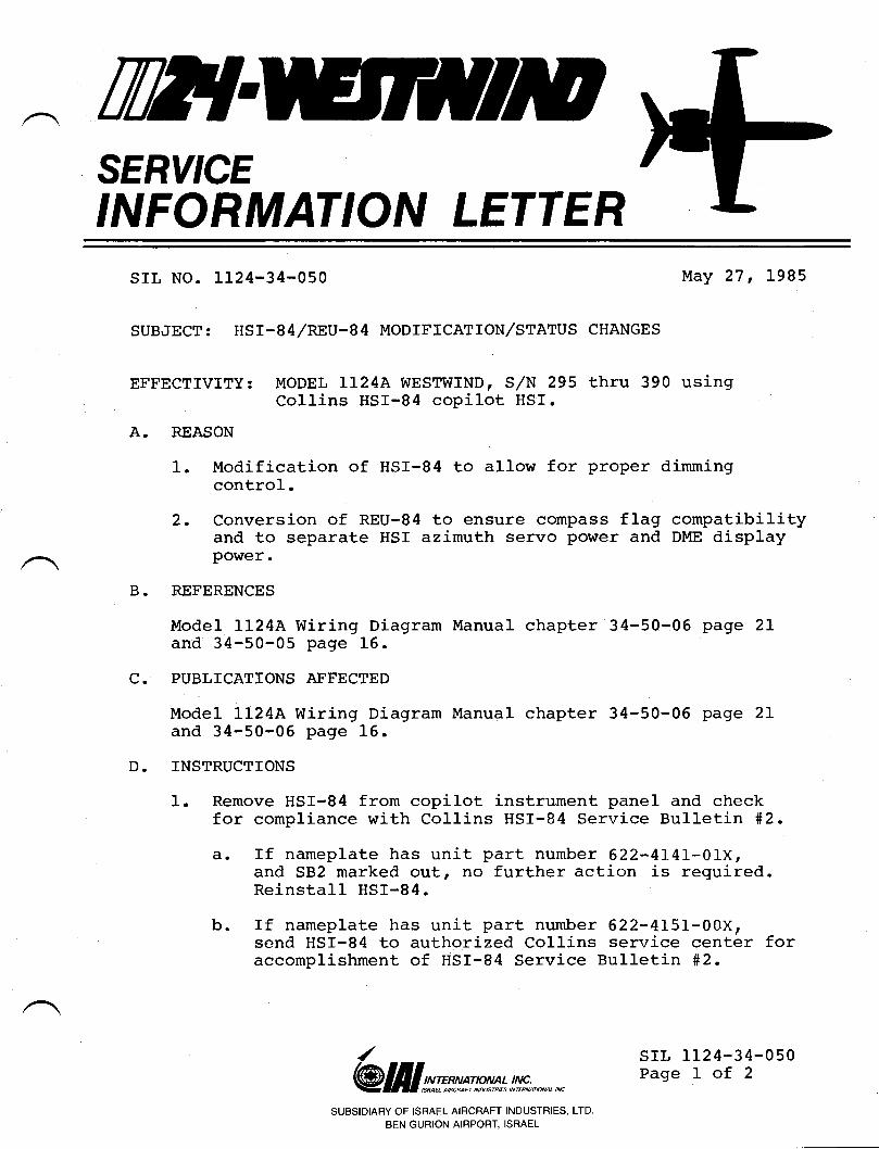
TilflSERY'CEINFORMATION LETTER
SIL NO. l-L24-34-050 May 27 , 1985
SUBJECT: HSr-84/REU-84 MODTFICATTON/STATUS CHANGES
EFFECTIVITYT MODEL Ll-24A WESTWIND I S/N 295 thru 390 usingCol-Iins HSI-84 copilot HSI.
A. REASON
1. Modification of HSI-84 Lo allow for proper dimmingcontrol.
2. Conversion of REU-84 to ensure compass flag compatibilityand to separate HSf azimuth servo power and DME displayPOWer.
REFERENCES
llode1 LL24A Wiring Diagram Manual chapter 34-50-06 pageand 34-50-05 page l-6.
PUBLICATIONS AFFECTED
Model LL24A Wiring Diagram Manual chapter 34-50-06 pageand 34-50-06 page l-6.
TNSTRUCTTONS
1. Remove HSr-84 from copilot instrument panel and checkfor compl-iance with Collins HSI-84 Service Bulletin #2.
a. ff nameplate has unit part number 622-4141-01X,and SB2 marked out, no further action is required.Reinstall HSf-84.
b. If nameplate has unit part number 622-4151-00X,send HSI-84 to authorized Collins service center foraccomplishment of HSr-84 Service Bulletin #2.
B.
c.
D.
2L
2T
/@ lf, I srx* p*t* !,!#;, *.,, *
SUBSIDIARY OF ISRAEL AIRCRAFT INDUSTRIES, LTD
BEN GURION AIRPORT, ISRAEL
srL LL24-34-050Page 1 of 2
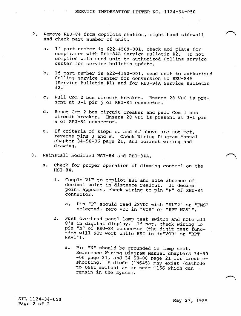
2.
SERVICE INFORMATION LETTER NO. 1124-34-050
Remove REU-84 from copilots station, right hand sidewalland check part number of unit.d. If part number is 622-4569-00I_, check mod plate for
complianee with REU-84A Service Bulletin #2. Tf notcomplicd with send unit to authorizcd Collins servicecenter for service bulletin update.
b. If part number is 622-4152-001, send unit to authorizedCollins service center for conversion to REU-84A(service Bulletin #1) and for REU-94A service Bulletin#2'
c. Purl com 2 bus circuit breaker. Ensure 28 vDc is pre-sent at J-l pin j of REU-84 connector.
d. Reset Com 2 bus circuit breaker and pult Com l_ buscircuit breaker. Ensure 28 VDC is present at J-1 pinW of REU-84 connector.
€. Tf criteria of steps c. and d.'above are not met,reverse pins J and W. Check Wiring Diagram Manualchapter 34-50=06 page 2l-, and correct wiring anddrawing.
Reinstall modified HSI-84 and REU-84A.
€I. check for proper operation of dimming control on theHSr-84.
l-. Couple VLF to copilot HSI and note absence ofdecimal point in distance readout. If decimalpoint appears, check wiring to pin ,rpr of REU-94connector.
E. Pin rrprr should read 28VDC with "VLF2,' or "FMS"selected, zero VDC in IVORI or ,'RpT NAVIn.
2. Push overhead panel lamp test switch and note all8's in digital display. ff not, check wiring topin rrN, of REU-84 connector (the digit test func-tion will NOT work while HSI is in',VOR,' or ',RpTNAV]").
a. Pin xNrr should be grounded in lamp test.Reference wiring Diagram Manual chapters 34-50-06 page 2I, and 34-50-06 page 2L for trouble-shooting. A diode (IN645) may exist (cathodeto test switch) at or near T156 which canremain in the system.
3.
srl. 1124-34-050Page 2 of 2
May 27, 1985
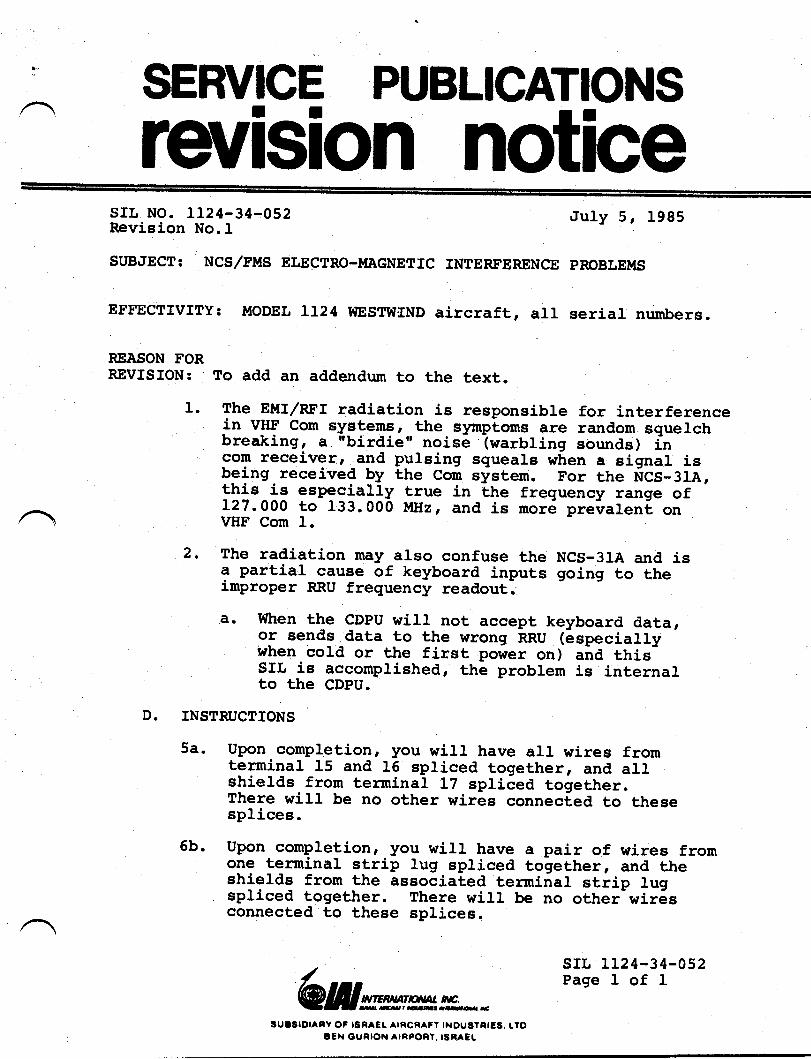
?" SERVICE PUBLICATIONS
revlslon notlceII
srL No. LL24-34-052Revision No.L
SUBiIECT: NCS/FMS ELECTRO-MAGNETIC
.Iuly 5, 1985
INTERFERENCE PROBLEUS
REASON FORREVISfON: To add an addendum to the text.
1. The EMIr/RFI radiation is responsibJ.e for interferencein v-tt!' con syg!,ems, the symplocrs are random squelchbreaking, a "birdie', noise (warbling sounds) incom receiver, and pulsing squeale when a signal isbeing-received by Lrre corn sfstem. For the frcs-ate,thls-1! especia|lV true in the frequency range of127.000 to L33.000 MHz, and is more prelal.ent onVHF Com I.
2. The radiation nay also confuse the NCS-3IA and isa partial cause of keyboard inputs going to theimproper RRU frequency readout.
a- lilhen the cDpu will not accept keyboard data,or eends data to the wrong nnU (especiallywhen cold or the first power on) aira tfris-srl is accourprished, the problem is internarto the CDPU.
D. INSTRUCTIONS
5a. Upon completion, you wiJ.l have alL wires fromterminal 15 and lG spliced together, and allshields from terminaL LT spliced together.There wilr be no other wires connected to thesesplices
5b. upon completion, you will have a pair of wires fromone terminal etrip lug spliced together, and theEhielde from the associated terminal strip lugspliced together. There wirl be no other wir6sconnected to these spJ.ices.
EFFECTMTY; MODEL LL24 VTESTW'IND aircraft, all serial numbers.
srr, tL24-34-052Page I of I
"IIERT{AT'dAL rc.
&&rlgn.ryd-
gutSrorAtY oF lgRAEt alncRAFt tNou6TntEs, Lro3€il OunloN AlnPont, tse^CL
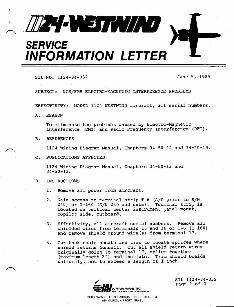
TWTSERY'CEINFORMATION LETTER
srl, No. Lr24-34-052 June 5, 1985
INTERFERENCE PROBLEMSSUBJECT: NCS,/FMS ELECTRO-MAGNETIC
EFFECTfVITY: MODEL LI24 WESTWIND aircraft, all serial numbers.
A. REASON
To eliminate the problems caused by Electro-MagneticInterference (EMI) and Radio Frequency Interference lnrr).
B. REFERENCES
LL24 wiring Diagrarr Manual, Chapters 34-50-L2 and 34-50-13.
C. PUBLICATIONS ASFECTED
LL24 Wiring Diagram Manual, Chapters 34-50-12 and34-50-13.
D, INSTRUCTIONS
1. Remove all power fron aircraft.
2. Gain access to terminal strip T-6 (A/C prior to S,/N240) or T-160 (s,/N 240 and subs) . Terminal strip islocated on vertical center instrument panel mount,copilot side, outboard.
3. Effectivity, all aircraft serial numbers. Remove allshielded wires from terminals 15 and 16 of T-6 (T-160)and remove shield ground wire (s) from terminal I7.
4. Cut back cable sheath and ties to locate splices whereshield returns connect. Cut all shield return wiresoriginally going to terminal L7, splice together(maximum length 2") and insulate. Trim shield braidsuniformly, not to exceed a length of 1 inch.
/ srl, LL24-34-852Page 1 of 2
@ lill vt'msp*t* !,!#;,*,*SUBSIDIARY OF ISRAEL AIRCRAFT INDUSTRIES, LTD
BEN GURION AIRPORT, ISRAEL
SERVICE INFORMATION LETTER 1124-34-052
5. Cut center conductors of aII wires removed fromterminals 15 and 16 to a lengLh not to exceed 2 inchesbeyond shield and splice together.
CAUTION
Any short circuit between theshield braid and center conductorin the preeeeding or followingsteps will cause failure of theNCS-3I CDPU.
6. Effectivity, aircraft, S,/N 187 thru 222.Perform the above procedure with each terminal strippair in sequence. Ensure each terminal pair isproperly isolated from the other terminal pairs.
A. Begin with T-6 terminals I and 2, taking eachterminal pair, in turn, until the pair onterminals 13 and 14 are compJ-eted. Do notinterfere with any other wires at T-6.
srr, LL24-34-052Page 2 of 2
June 5, 1985
TilT{SERY'CEINFORMATION LETTER
srr, No. II24-34-053
suB,lEcT: FMS-90/LRN-8s,/CnS-S00 BACKLTGHTTNG
August 9, 1985
EFFECTIVITY: IL24/LL24a S,/N,s prior to 392 with FMS-90/LRN-85,/GNS-500 installed as #f and/or #2 Vr,r NAV System.
A. REASON
Ensure proper strapping for maximum backlighting ofComputer OispJ-ay Units and Receiver Tune Units.
B. PEFERENCES
rL24 wiring Diagram Manual chapters 34-60-0r, 34-60-02 and34-60-03.
C. PUBLICATIONS AFFECTED
rr24 wiring Diagram Manual, chapters 34-60-0t, 34-60-02 and34-6 0-0 3 .
D. DESCRTPTION
(t) A continuity check of the Receiver Tune unit (RTU)connector is required to ensure proper voltage sourcefor the backlighting of the RTU.
A. Check the RTU-90 part number. If it ends j-n an oddnumber, O to 5VDC from center instrument paneldimmer must be observed at plug B2O7J2-9, originatingat T156-18.
Should the RTU P/N end in an even number, O to28VDC must be observed from console edge lightdimmer, originating from a splice at wire LL7E20near the passenger oxygen control panel.
/@ lill srwmn* t!!,*.,*,,n
srL 1124-34-053Page I of 2
SUBSIDIARY OF ISRAEL AIRCRAFT INDUSTRIES, LTD.
BEN GURION AIRPORT, ISRAEL
SERVICE INFORMATION LETTER NO. LL24-34-053
B. At RTU connector J2 see that the jumpers from pins10 and 11 return to airframe ground at a point onthe instrument panel support near the RTU.
(2) A continuity check of the Computer Display Unit(CDU-90/CDU-85) is required to ensure proper strappingfor the CDU backlighting.
A. At CDU-90/85 connector check for continuity betweenpins "D", rrNrr and ttJ. t' These three pins shouldread O to 5VDC with console dimmer rotation.
B. At CDU-90/85 connector check for continuitybetween pins t'8", rrprr and "H. " These threeshould read short to airframe ground, and mustbe grounded to a point near the CDU on panelsupport or the pedestal.
C. At Global CDU connector check for contj_nuitybetween pin rrP'r and airframe ground. pin mustbe grounded to a point near the CDU in thepedestal.
srl, 1124-34-053Page 2 of 2
August 9, 1985
rwtSERY'CEINFORMATION LETTER
srl, No. rLu-34-073 REVISION 1 May 29,1990
(This service information letter dated May 29, 1990, supersedes ServiceInformation Irtter No. 1 1z-3 4-w 3 dated July 10, 1989 in its entirety.)
SUBJECT: WEATTIER RADAR - COLIJNS IND.3OO WEATTIER RADARINDICATOR MANDATORY SERVICE BULI-ETIN
ALL LI24 I LLU AMODEL WESTWINDS WTITI COLLINSIND-3OO WEATHER RADAR INDICATOR INSTALLED
EFFECTWITY:
A. REASON
Several incidents have been reported of smoke being emitted from IND-300indicators in the cockpit.Investigation of the affected indicators revealed anarc between an internal resistor in the high voltage power supply to the chassis.This arc caused the outer cover of the highvoltage power."pplt to smolderand emit smoke.
B. REFERENCE
Rochvell Collins Mandatory Service Bulletin 18 to the IND-300radar display.
C. PUBLTCATIONSAFFEC1ED
None
D. DESCRIPTION
Rochvell Collins Mandatory Service Bulletin Number 18 has been issued tocorrect the problem. This bulletin is applicable to all IND-300 indicators in thefield that do not have Mod No. 18 marked off on the mod plate. The IND-300radar indicator can be identified as Collins PA',['s 622-$3{-ffiL,622-4331-N2or 622-4331-003. Contact your Roclnvel[ Qsllins dealer for further information.
July 1.0, 1989Revision 1, May 29,L9901013
$LLtU-34-073Page 1 of 1
n2{SERVICEINFORMATION LETTER
sIL NO. tt24-34486 REVISION I
TRANSMTTAL SIIEET
April 4,l99l
This sheet Eansmits Revision 1 to Service Information Irtter No. 1124-34{86, datedFebruary 13,199L, titled 'Navigation - Weather Radar Antenna.
RFASON FOR RFVISION
To add CAUTION to prevent further damage to the tilt drive mechanism.
This is a COMPLETE REVISION. Remove and discard all pages affected by thisrevision.
I IST OF FFFFCTryF PAGFS
PAGF NO. DATF
I April,4,l99L
PRFVTOUS RFVISTONS OF SrI I lt4-34486
None
TransmitalPage I of 1
April 4,l99l
Til]TSERY'CEINFORMATION LETTER
RR
SERVICE INFORMATION I,ETTER, NO. 1T24.34486 February 13,l99l
SU&IECT: NAVIGATION. WEATHER RADAR ANTENNA
EFFECTIVITY: MODEL ll24lll24[ WESTWIND, all serial numbers withCollins ANT-318 or ANT-318A Weather Radar Antennainstalled.
A. REASON
Some radar installations are experiencing damage to the tilt mechanism in ilreform of broken teeth on the sector or tilt motor gear.
B. REFERENCE
Collins Service Bulletin No. 6 to the ANT-310, ANT-310A, ANT-312,ANT-312A, ANT-318 and ANT-318A Weather Radar Antennas, titled,IMPROVE TILT SECTOR GEAR RELIABILITY.
C. PUBLICATIONS AFFECTED
1124 Westwind Airplane Flight Manual.ll24l Westwind Airplane Flight Manual.
D. DESCRIPTION
Referenced service bulletin modifies the ANT-318 and ANT-318A WeatherRadar Antennas by replacing the Tilt Sector Gear and the Tilt Motor Assembly ofthe antenna drive mechanism with a new and improved Tilt Sector Gear and TiltMotor Assembly.
Contact your Collins dealer for further deAils.
CAUTION: TO PREVENT FURTHER DAMAGE TO TILT DRIVEMECHAMSM, ENSURE RADAR SYSTEM IS TTJRNED OFFUNTIL ATTITUDE REFERENCE SYSTEMS ARE FULLYERECT AND VALID ATTITUDE DISPLAYS ARE PRESENT.
February 13, 1991
Revision 1, April 4,l99L5023
str. I t24-34486Page 1 of 1
RRRR
TW{SERVICEINFORMATION LETTER
SUBJECT:
EFFECTWITY:
A. REASON
August 23,19955023
Some radar installations are experiencing damage to the tilt mechanism in theform of broken teeth on the sector or tilt motor gear.
B. REFERENCE
Collins Service Bulletin No. 6 to the ANT-310, ANT-310A, ANT-312,ANT-312A, ANT-318 and ANT-318A Weather Radar Antennas, titled,IMPROVE TILT SECTOR GEAR RELIABILITY.
C. PUBLICATIONSAFFECTED
None.
D. DESCRIPTION
Referenced service bulletin modifies the ANT-318 and ANT-318A WeatherRadar Antennas by replacing the Tilt Sector Gear and the Tilt Motor Assemblyof the antenna drive mechanism with a new and improved Tilt Sector Gear andTilt Motor Assembly.
Contact your Collins dealer for further details.
CAUTION: TO PREVENT FURTHER DAMAGE TO TILT DRIVEMECHANISM, ENSURE RADAR SYSTEM IS TURNED OFFUNTIL ATTITUDE REFERENCE SYSTEMS ARE FULLYERECT AND VALID ATTITUDE DISPLAYS ARE PRESENT.
NAVIGATION. WEATHER RADAR ANTENNA
MODEL l\24lI124A WESTWIND, all serial numbers with CollinsANT-318 or ANT-318A Weather Radar Antenna installed.
sIL 1124-34-lT2Pase 1 of 1
IHSERVICEINFORMATION LETTER
SM,VICE INTORMATION LETTER NO. 1 T24-51-IO5 August 3,1994
SUBIECT: STRUCTURES - INSPECTION AND PREVENTATIVEMAINTENANCE OF AIRCRAFT STRUCTURE FORCORROSION AT ANTENNA MATING SURFACES.
EEFECTMTY: MODEL Il24 WESTWIND. all serial-numbers.
A. REASON
To provide information for the inspection of aircraft structure for corrosionand preventative maintenance at antenna mating surfaces.
B. REFERENCE
None
C. PUBLICATIONSAFFECTED
None
D. DESCRIPTION
Aircraft structural corrosion under antennas is commonly caused by moisturepermeating between the two surfaces. It also may be caused by aircraftwashing chemicals and paint stripper.
It is recommended that the outer edges of antennas be inspected periodicaltyfor cracked or missing sealant. Also inspect antenna bases for cabin pressureleaks by evidence of dark streaks projecting from the sealed areas.
If the outer edge of an antenna shows any of the above discrepancies, it isrecommended that the antenna be removed and the mating surfaces, inspectedfor corrosion and cleaned as necessary. It is also recommended to applyalodine treatment to exposed contact areas to ensure long term antennabonding and to assist in the prevention of future corrosion.
il'J:i,#'::"i';gll',l*,llf ,,Troilff ':3;"ifi;3i,:l:liTi::13:,::'::ffi J:"hidden under external antenna bases.
August 3,19945278
srr- 1124-51-105Page 1 of I
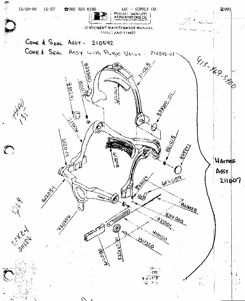
12:57 8302 323 0.195 AAC - SIIPPLY C0.
lHiffi*rtqf+.j,.)c Mtt'HEH7 Va I t{ TE NANCF_ M/. t,: U/l L
t ldii: J F,tvf--l 1t,u?c
Co*e A S"* &ss{ - ?lo6qe
-tr-,6Q.r*l
"j'1
t.I
i
I
I
, ill*rw
i A+Er
1 Lttl
\\r
Yt_r
Coue
-\
*ttt. /"fl'
{r
,\.,a\
'-t{
*rq{r*\
tt
"-1n i
i,it . i.
t----- ,_','+.r '\r-,-
. ,,i':,1" ,t ' .,,
t SsA" A*rq Lr i Sr ?r*\B \J,{u_* *. ? r r
H;],'kI*:: hrt I
\u,_]/ -Hm.N { f/\
{?r#i;F tE # ,n r-J
o'i\'*6r-*.-,*W:Lf' Yt*'ie,rf,,r"r*ffi*.tff*:*kq "+,
t*fut /i\,
j.
TWISERY'CEINFORMATION LETTER
B.
srr, No. LI24-35-015
SUB.]ECT: OXYGEN SYSTEM - TIME UNIT
EFFECTIVITY: MODEL LL24/LLz4A, allA, REASON
February II, 1985
CHATiTGES
serial numbers.
Overhaul or Rep]gce
o/c
To remove the 5000 hour or 5 year overhaul requirement onoxygen regulators.REFERENCES
Puritan Bennet Memo dated ilune 25, 1980.S.I.L. No. #15LL24 Maintenance Manual., Chapter 5.
PUBLICATIONS AFFECTED
LL24 Maintenance Manual., Chapter 5.
DESCRIPTION
The following changes have been approved forincorporation into the replacement and overhaul scheduleof LL24 Maintenance Manual_, Chapter 5.
c.
D.
Component,
Regulator
Part No.
r01202-11
/@ lill grme** !,!!u'*, *.,,*
SUBSIDIARY OF ISRAEL AIRCRAFT INDUSTRIES, LTD.
BEN GURION AIRPORT, ISRAEL
srl.. 1124-35-015Page L of I
rilI{SERY'CEINFORMATION LETTER
A.
B.
srl, No. IL24-35-035 March 20, 1985
SUBJECT: STOWAGE OF EROS OXYGEN MASK P/N MC-1013-12
EFFECTIVITY: MODEL LL24/IL24A WESTWINDS, serial number 187and subs. with Eros Oxygen Masks.
REASON
To prevent mask leakage around the facial seal due to HeatSoaking.
REFERENCES
IL24/LL24A Illustrated Parts Catalog, Chapter 35.
PUBLTCATTONS AFFECTED
None
INSTRUCTIONS
Due to the method of stowage of the oxygen mask and inflat-able head harness, the oxygen mask facial seal becomesdeformed from on-ramp heat soaking. This harness isdifficult to deflate for stowage and can inflate in thestowed position if the oxygen shut-off valve is not secure.This increases the harness size and puts pressure on thefacial seal which becomes distorted when heat soaked. rtis recommended that harness be sufficienLly deflated so asnot to put pressure on mask r oE stow masks with harness outof the mount while aircraft is on the ground in direct. sun-light.
c.
D.
/ srl, 1124-35-035Page 1 of I@ lfil st'mrw* !,t%;,*,n
SUBSIDIARY OF ISRAEL AIRCRAFT INDUSTRIES, LTD.
BEN GURION AIRPORT. ISRAEL
TTT{SERY'CEINFORMATION LETTER
SERVICE INFORMATION LETTER NO. 1124-35.082 August 8, 1990
SUBJECT: OXYGEN - EROS MC-SERIES MASK-REGUI-ATOR ASSEMBLYOVERT{AUL INTERVAL INCREASE.
EtrTECTIVIrY: X?#*.l\X#,ff
wESrwIND, udth ERos Mask-Regulator
A. REASON
Due to reliability experience, Scott Aviation has recommended a revisedmaintenance policy for MC Series Mask-Regulator Assemblies.
B. REFERENCE
Irtter from Scott Aviation to all equipment manufacturers.n%nn4 AWestwind Maintenance Manual, Chapter 5- 10-00.
C. PUBLICATIONSAFFECTED
L1241 tlz4[Westwind Maintenance Manual, Chapter 5- 10-00.
D. DESCRIPTION
The Ll24l ll24 AWestwind Maintenance Manual, Chapter 5- 10-00,OverhauUReplacement Schedule for the EROS Mask-Regulator AssemblyP/N MC-1013-01 or -02is revised as follows:
3 years - factory functional test
6 years - factory overhaul
August 8, 1990
Lunsrt.1124-35-082
Page lof.2
SERVICE INFORMATION LETTER NO. 1 12 4-35 -082
The approved agency to perform these maintenance tasla is:
Scott Aviation225E;lie StreetI-ancaster, NY 14086Phone: 716-683-5100Fax: 716-681-1089
Advance notice of mask shipment is recommended and can expedite refurn.
sILl124-35-082Page2 of.Z
August 8, 1990
TW{SERVICEINFORMATION LETTER
SRVICE INTORMATION LETTER, NO. 1 124-35-083 October 1, 1990
SUBIECT: OXYGEN - SHUTOFF VALVE LUBRICATION
EI|FECTMIY: MODEL lI24lIL24A WESTWIND. all serial numbers.
A. REASON
To provide lubrication information for the oxygen shut off valve.
B. REFERENCES
None.
C. PUBLICATIONS AFFECTED
None.
D. DESCRIPTION
If an oxygen shut off valve becomes stiff and hard to operate, it may belubricated with grease which meets MIL SPEC M[--G-276I7.
There are several commercial brands which meet this MIL SPEC.The vendor listed below has several brands available and can provideinformation on them:
Aviation Consumables, Inc.P.O. Box 272054000 Red Bank RoadCincinnati, Ohio 45227Phone: 513-561-9977
October 1, 1990
1025sL 1124-35-083
Page 1 of 1
TilHSERY'CEINFORMATION LETTER
SIL NO. IL24-52-034 April 24, 1985
SUBJECT: PREVENTION OF WATER FREEZING IN CABIN DOORS Al{DBAGGAGE DOORS
EFFECTIVITY: LL24/LL24A I,IESTWfNDS, all serial numbers.
A. REASON
To alert operators of precautions which need to be followedafter the aircraft is washed or after being exposed to heavyprecipitation whiLe parked.
B. REFERENCES
None
C. PUBLICATIONS AFFECTED
None
D. DESCRIPTION
The possibilJ-ty exists for moisture to be introduced intodoor seals and door latch mechanisms during routine aircraftwashing and/or by being exposed to heavy precipitation whileparked outdoors.
It is recommended that the entrance, and baggage doors beopened and checked for the presence of moisture which mayfreeze and cause difficulty in operating latches and doors.
Wipe down seals thoroughly and spray or wipe on a lightcoating of silicone lubricant.
Check door latch mechanisms and their covers for moistureand spray latch mechanisms with LPS-2, WD-40 or anequivalent product.
/
@ lil grmtpmt !,!!uc*,*,,*
SUBSIDIARY OF ISRAEL AIRCRAFT INDUSTRIES, LTD.
BEN GURION AIRPORT, ISRAEL
srl, LL24-52-034Page 1 of 1
May 2, 1989
IMPROVED REMOVAL/ INSTALLATION
CANCELLATION NOTICE
This service bulletin is hereby cancelled forthwith. Thecontained in this service information letter is presentlyreviseQ in its entirety and wiII be published at a later
informationbeing
date.
"- 5U"-(Thomas VaiIManager, Technlcal Services
SERVICE PUBLICATIONS
revision notice
SIt No. 1124-56-029Revision No. 1
SUBJECT: COCKPIT SIDE WINDOWSPROCEDURES
^
rHSERY'CEINFORMATION LETTER
B.
SIL NO. 1124-56-029 tvtarch 20, 1985
SUBJECT: COCKPTT SIDE WINDOWS IMPRO\ED REMOVAL/TNSTALLATIONPROCEDURES
EFFECTIVITY: MODEL LL24 WESTWIND, all serial numbers.
A. REASON
To provide an improved method for replacement of the cockpitside-windows.
REFERENCES
LLz4 Aircraft Maintenance Manual, Chapter 56.
PUBLICATIONS AFFECTED
LL24 Maintenance Manual, Chapter 56.
DESCRTPTION
Instructions outlined in this Service Information Letterrevise the disassembJ"y, replacement, and reassemblyprocedures currently present in the Aircraft MaintenanceManual. The operator is advised to refer to theinstructions contained herein when replacing the windowpanels. Changes will be made to Chapter 56 of theMaintenance Manual to reflect the new procedures duringthe next scheduLed revision.(a) Remove direct-vision window,
(b) Remove cockpit interior furnishing as required tofacilitate removal of all fasteners securing pilotside-window retainer (See Figure 1).
c.
D.
/
@ lII gmwe*n* !,!!u'*n *..,*
SUBSIDIARY OF ISRAEL AIRCRAFT INDUSTRIES, LTD.
BEN GURION AIRPORT, ISRAEL
srL LL24-56-029Page I of 5
SERVICE INFORMATION LETTER NO. LL24.56-029
(c) Mask aII areas surrounding side-window retainer.(d) Remove all perimeter fasteners as indicated in
Figure I (numbers 37-39).
(e) Separate retainer,/window assembly from fuselagestructure.
(f) Proceed with removal and replacement of side-windowpaners and spacer as outlined in chapter 56-10-00.During installation of the new window panels, attentionshould be given to the fit of the outei window panerinto the side-window retainer. To ensure the bestoverall fit, the .z5o in. fastener holes previouslydrilled in the new window panel may be eniarged to amaximum diameter of .2gs inch. t'tiirimum edge distanceof all holes must be maintained at l.7D in all cases.rnsert all fasteners roosely. righten the middle of thepanel sides, working out to the corners in a crisscrosspattern.
(g) Fina1 torque all window double-panel fasteners to 40-45inch-pounds.
(h) Prior to reinstallation of the side-window retainer,remove all old sealant from the faying surfaces of theairframe structure and window retainer. Assure bothsurfaces are clean prior to application of new sealant.Refer to the aircraft Maintenance Manua1, Chapter53-00-00, Fuselage Sealing, General MaintenancePractices for instructions covering proper searing ofside-window retainer to fuselage. Appricable searantis: 3M-8C1239, Class B.
(i) Reinstall retainer using cl-eaned surface hardware.Ensure Ec1239 searant is applied to the underside ofeach fastener before assembly.
(j) Assemble all fasteners to airframe roosely. Tightenfasteners gradually in a crisscross pattern, withattention given to even application of torque,drawing retainer into fuselage structure. -Finaltorque all retainer fasteners to 3o-35 inch-pounds.
(k) Remove excess 8C1239 sealant from alI areas asnecessary. Fair in joints between window/retainerand retainer/fuselage skins with excess sealant.
srl, 1124-56-029Page 2 of 5
March 20, 1985
SERVICE TNFORMATION LETTER NO. IL24-56-029
(1) After curing of sealant, refinish retainer andfasteners as required.
(m) Reinstall interior furnishings.(n) Remove protective covering and clean windows. Refer
to Chapter 55-00-00.
2. Procedures for replacement of the copilotrs side-windoware essentially identical to those for the pilot's side.(Reference Figure 2 for fastener identification).
srL LL24-56-029Page 3 of 5
March 20, 1985
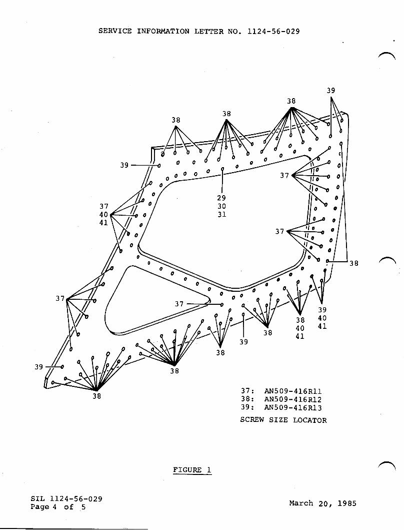
SERVICE INFORMATION LETTER NO. LL24-56-029
37 t Alr509-416RIl38: AN509-416R1239: Al',I509-416Rl3
SCREW SIZE LOCATOR
srr, IL24-56-029Page 4 of 5
o
o
o
0
(;
FIGURE 1
March 20, 1985
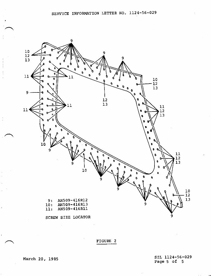
SERVICE INFORMATION LETTER NO. LL24-56-029
9
-i<
10L2I3
10L2I3
oI111L213
l1I213
srl, LL24-56-029Page 5 of 5
\o
3
h{0
9
9: AN509-416R12I0: AN509-416RI3Il: Al.1509-415RII
SCREW SIZE LOCATOR
10L2I3
March 20, 1985
FIGURE 2
rw{SERY'CEINFORMATION LETTER
SERVICE INFORMATION LETTER NO. 1124.56.081 June 15, L990
SUBJECT: WINDOWS - COCKPIT SIDE WINDOWS
EFTECTWITY: MODEL LL?4|LL?4AWESTWIND, il serial numbers.
A REASON
To alert ovrners/operators and Service Centers of cockpit side windows PA.{
3430L7-75/51 and P/N 343003-4l5lthat have been manufactured without theapproval of Israel Aircraft Industries Ltd. (IAI) or Astra Jet Corporation (AIC).
B. REFERENCE
LlUl ll%AWestrvind Maintenance Manual, Temporary Revision 56-1.
C. PUBLICATIONSAIFECTED
None
D. DESCRIPTION
A Westwind cockpit side window was received by a Service Center that could notbe identified as an IAVAIC approved part. The Service Center contacted AJCand after investigation it was confirmed that it was a bogus part.
Orvners/operators and Service Centers should beware of parts that are notapproved by IAI or dIC and tagged accordingly.
Our part numbering system strictly follows our drawings and is easily identified.
Contact AJC - Technical Services, Wilmington, DE at (302) 322-7240if thevalidity of a part is in question, to ensure the continued airworthiness of the
aircraft.
sIL NO. L124-56-081Page 1 of 1
June 15, 1990
TilHSERY'CEINFORMATION LETTER
SIL NO. 1124-71-071 April 4t 1988
SUBJECT: EXHAUST ENGINE TAIL PIPE CLAMP TORQUE CHECK
EFFECTMTY: MODEL 1124/1124A WESTWIND, all serj-al numbers
A. REASON
To caution operators against overtorquing theF1 0A-5-SCP201 -3 tail pipe clamp.
B. REFERENCES
1124/1124A Maintenance Manual, Chapter 71-00-01 page 238.
C. PUBLICATIONS AFF'ECTED
NONE
D. DESCRIPTION
Faj-lures of the subject clamp have been reported and havebeen attributed to overtorquing of the V-band clampsduring installation. Cracks in the trunnion area canresult. This cracking may lead to loosening of the clampand possible loss of the tail pipe.
The procedures in the 1124/1124A maintenance manual shouldbe carefully adhered to during installation of the tailpipe. The correct torque of 45 in-lbs is engraved on theclamp flange.
/@ lfil srxspx* !,!#n *.,*
SUBSIDIARY OF ISRAEL AIRCRAFT INDUSTRIES, LTD,
BEN GURION AIRPORT, ISRAEL
srL 1 124-71 -071
SERVICE PUBLICATIONS
revision notice
SUBiIECT: ENGTNE FUEL COMPUTER EMI FITTER INSPECTION.
REASON FORREVISfON: To change the Chapter number of SIL,
SIL NO. LL24-28-0I8 should be changed to readSIL NO. LL24-73-018 on alJ. pages.
srl, No. 1124-73-018Revigion No.1
OPTTONAL
sug919|ARY OF rsRAEt ATFCRAFI lNDUgTnl€S. Ll0. E€X OUNION AINPORI. ISRAEI
,June L4, 1985
sB 1124-73-018Page I of t
TWTSERY'CEINFORMATION LETTER
SUBJECT: ENGINE FUEL COMPUTER
srL No. l.124-28-018 January 24 ' 1985
EMI FILTER INSPECTION.
all serial numbers.EFFECTMTY: MODEL LL24/LL24A,
A. REASON
1. To prevent inadvertent Fuel Computer Manual Mode_operationshould filters become open or installed improperly.
2. To ensure proper procedures for installation of EMIfilters.
3. To introduce an inspection procedure to identifysuspected defective filters.
PUBLICATIONS AFFECTED
IL24/LI24A Wiring Manual, Chapter 28-20-01.LL24/LJ.24a uaintenance Manual, Chapter 78-30-00.
DESCRIPTION
1. It has been found that some EMI filters have beeninstaLled incorrectly and/or damaged during installation.It is suggested that the filters be inspected accordingly.
(a) Filter mounting holes should be cleaned and polishedto ensure a good electrical bond. Apply Iridite L4-2or Penetrox to Prevent corrosion.
B.
c.
/ srl, LI24-28-018Page I of 6
@ lI I w:m p*n :,!,!)F;., *.,, *SUBSIDIARY OF ISRAEL AIRCRAFT INDUSTRIES, LTD
BEN GURION AIRPORT. ISRAEL
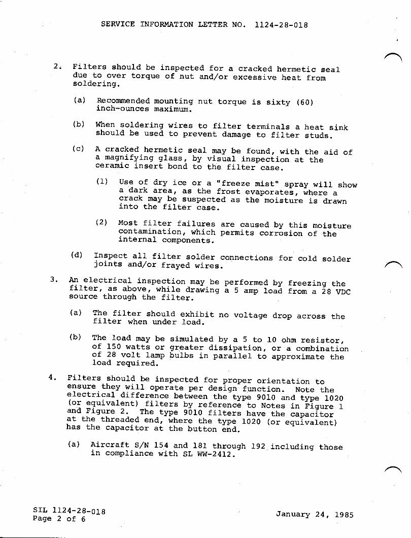
SERVICE INFORMATION LETTER NO. LI24-28-018
2. Filters should be inspected for a cracked hermetic sealdue to over torque of nut and/or excessive heat fromsoldering.
3.
(a) Recommended mounting nut torque is sixty (6o)inch-ounces maximum.
(b) when soldering wires to filter terminals a heat sinkshould be used to prevent damage to filter studs.(c) A cracked hermetic seal may be found, with the aid ofa magnifying glass, by visual inspeci.ion at theceramic insert bond to the filter case.
(1) use of dry ice or a "freeze mist', spray wirl showa dark arear ds the frost evaporatel, where acrack may be suspected as the moisture is drawninto the filter case.
i2) Most filter fairures are caused by this moisturecontamination, which permits corrosion of theinternal components.
(d) rnspect all firter sorder connections for cold sorderjoints and/or frayed wires.An electrical inspection may.be performed by freezing thefilterr €rs above, while arawing I s amp load from a 2g VDCsource through the filter.(a) The filter should exhibit no voltage drop across thefilter when under load.(b) The load may be simurated by a 5 to lo ohm resistor,of 150 watts or greater dissipation, or a combinationof 28 volt lamp bulbs in parallel to approximate theload required.Filters should_be inspected for proper orientation toensure they w111 0perate per design function. Note theerectrical difference between the type goro and type
-1020(or equivalent)_filters by referenc6-to Notes in 'figure tand Figure 2. _The _type 9or0 firters have the ""p"-iio,at the threaded end, where the type Lo20 1or equivalent)has the capacitor at the button ena. -=--
(a) Aircraft s/N 154 and r8r through rg2 incl_uding thosein compliance with SL WW-24L2.
4.
srl, 1124-28_018Page 2 of 6
January 24, 1985
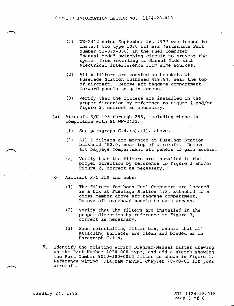
SERVICE INFORMATION LETTER NO. LL24-28-018
(1) WVI-2412 dated September 26, L977 was issued toinstall two type 1020 filters (alternate PartNumber 51-379-000) in the Fuel Computer"Manual Mode" switching circuit to prevent thesystem from reverting to Manual Mode withelectrical interference from some sources.
(21 A11 6 filters are mounted on brackets atFuselage Station bulkhead 4L9.84, near the topof aircraft. Remove aft baggage compartmentforward panels to gain access.
(3) Verify that the filters are installed in theproper direction by reference to Figure 1 and/orFigure 2, correct as necessary.
(b) Aircraft S/N 193 through 258, j-ncluding those incompliance with SL WVI-24I2.
(1) See paragraph C.4. (a). (1). above,
(2) All 6 filters are mounted at Fuselage Stationbulkhead 452.0, near top of aj-rcraft. Removeaft baggage compartment aft panel-s to gain access.
(3) Verify that the filters are installed in the
FI;i:: i:':::l:l.ox"'i5::::::,:o Fisure L and/or
(c) Aircraft S/N 259 and subs:
(1) The filters for both Fuel Computers are locatedin a box at Fuselage Station 473, attached to a
;:;:;.*:H":":*I3u"5l"3i3ni3"n:?1"3::3:3:'(2) Verify that the filters are installed in the
::::::.u::";::::"3lol""rence to Fisure 3,
(3) When reinstalling filter box, ensure that allattaching surfaces are clean and bonded as inParagraph C. l.a.
5. Identify the existing Wiring Diagram,Manual filter drawingas the Part Number 1020-000 type, and add a sketch showingthe Part Number 9010-100-0013 filter as shown in Figure 1.Reference Wiring Diagram Manual Chapter 28-20-01 for youraircraft.
SIL 1124-28-018Page 3 of 6
,January 24, 1985
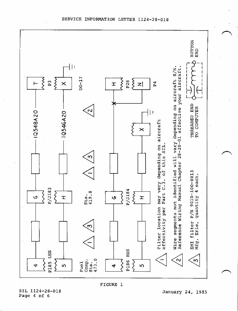
zFEiO2Z@Fl
r-9-tr( |tts |tFltti)- |t\ |
D IFtL_d_,
ZM14 14
HODHAot<oF]O
HF
Z+)\ tl{urd
u{Jor+.t H(Il 'r{l|doHH.AjdoHo0)O'.{crJ..1 O6c)d t{ro tl{O.{ O0)(J-l
o>tll.r odc{>loF{ C\-{..{ t{3(l)
+JdPlod.r{ tqrU...{+J F{qrdo5dq.'l dt+JOU'
..Jot.l+J ..{dEoEctUtOCJgoo
$.{ool{ t+{..{ OBfi
+Jq{dr.lot{..{ddFlOH
(ntndu-4,4ld.qH+JoO{ lHood> cf)${OU
+Jhl{ddEACt{oc)..{ Or+Jd>o+JO '.{r{>
...1
t{ {Joo{JoF{ t}{.Fl q-{
frO
.c,-{O{.O E 6..)5 O+Jr-hU(,)s
(nFfa
}]rOco
-lA
cn-| .o.qoc)rdo(DFl sfIo>-l +,O.FlOr +Jqzd\tAttg\oo+J ..{-{ t{...1 rlLl{
HblE '+{FIE
x
2i-
)!o)
\I@FlF)
A
ilIt--s[l:,_T--+ t3
tltlll-/1ooSlNC\l\
@(.0$$1r) .O
99
@
d ol+J F{ul <r
oo@Fll')
A
,T
ro
(9
rf,(a
SERVTCE INFORMATION LETTER 1124-28-018
srr, Lt24-28-018Page 4 of 6
FIGURE IJanuary 24, 1985
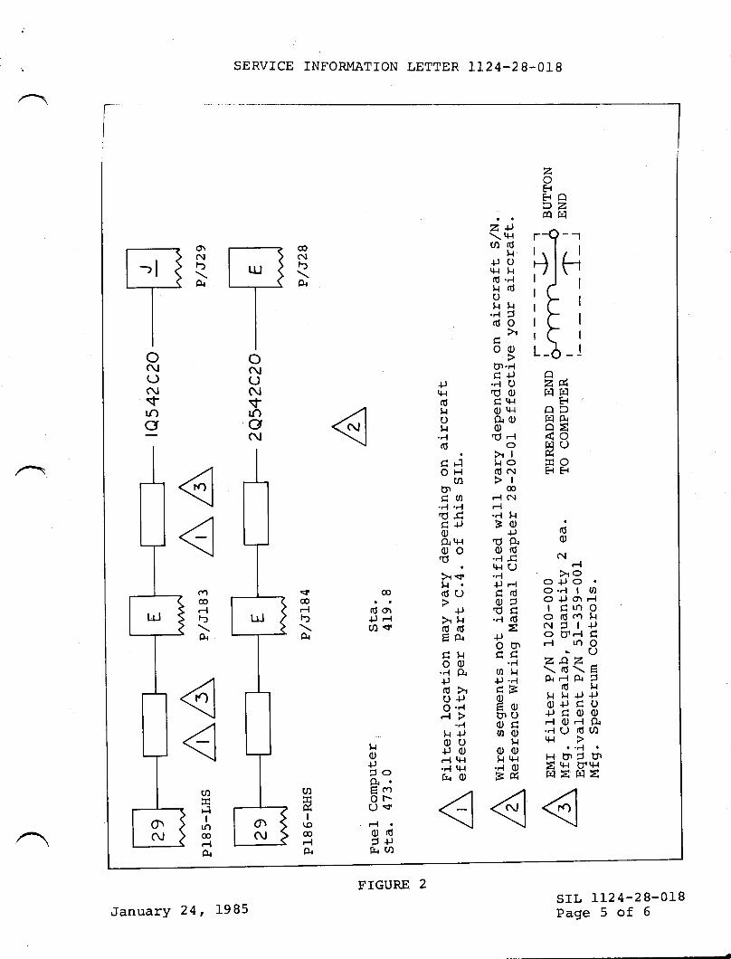
SERVICE INFORMATTON LETTER 1124-28-018
rI
II
(d(u
c!FI>oo+Jo
O'F{ | OO+rOl-{tqtnoodoog
N5I+Jo tt-l dr{ toO
'c)z9z\d\EA-.lA 5d l.l
t{ t{ lJ +)O+J H otJqoo.-.1 O rl Pr..{U dC,.lt+{
. .t_l
H ur' tn
= tH ttrH
FTEHE
Z1)\t+{(n(0t{
+JUr{i l{d"lg(6og l.{..1 Jdo
>r
ooUt -.{c+J.r{ Od0)H tl-'l
OtHP{(I)0)O-lo>ll{o(dN>l
@
-l C!
.r{ gts0)
+JdP{od'.{ 3I1{(J._l+J F{gdo5dd..{ d
E+Joo'
.-lurl{+J ..1dB()Eq)btuogmc)
11oot{ t+{..'l C)EE
+,rlldt{ot{
.Fld
CFIOH
UItttCo.-1.'{d.cH+Ja)Q.t t+'{
ood>lst{dCJ
{J>f{ddEAHt{oo.''l gl+Jdxo+)O'-lF{>
.Fll{ {Joc)+JOF{ t+{
'r{ l+{tqO
@
Oot+J Flu) <r
t{0)+J5oPr'EcoOr-()S
F{
o(darh(n
T-T-
$@F{F)
A
(/)H
I\0@FlA
oN(JNvlooc\l
lrJ
olN
aa@rlF)
A
(/)H
FlI
tn@rlA
IJ
o\N
zHFO>zO f']
r-Q-rrll'\l/ |
HIH:/t\') I
tl:>ltL I
r( |
L-6 -lzg,HF1
HODt4AOE<otrl (J&HH
oN(JNsfroo
srl, IL24-28-018Page 5 of 6
T.IGURE 2
JanuarY 24, 1985
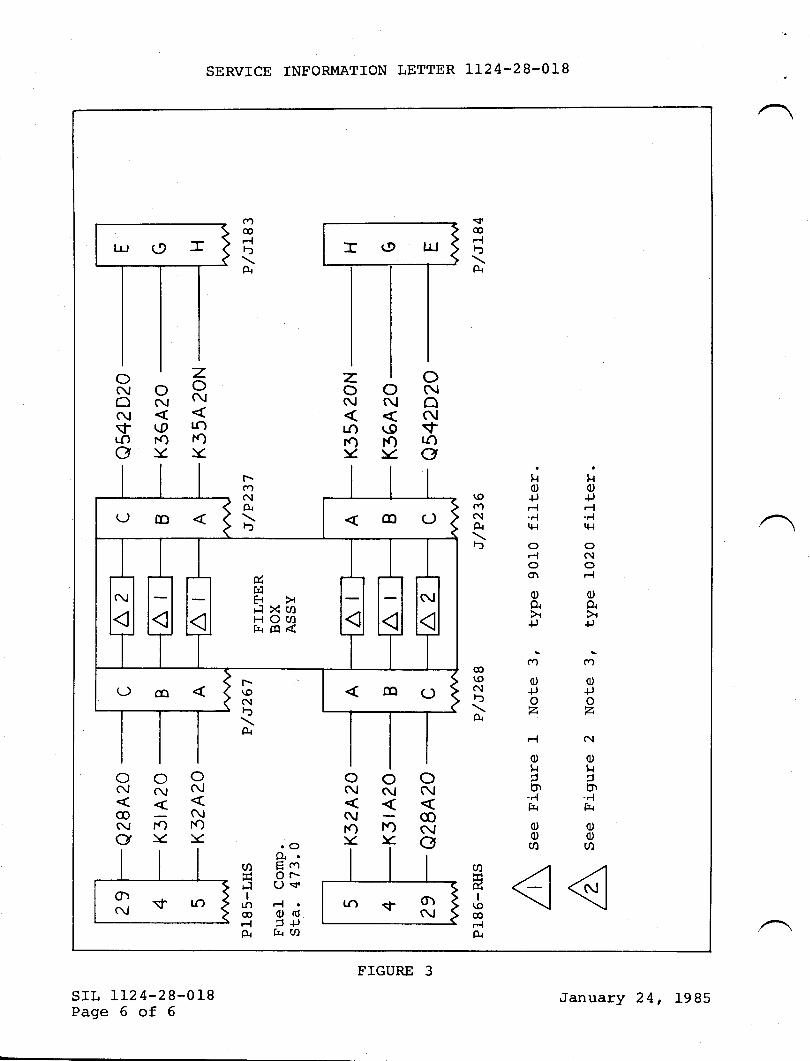
SERVICE INFORIvIATION LETTER 1124-28-O1B
srl, LL24-28-018Page 6 of 6
Ht{oc)\0 +J +JCn -{ F{C! .r.l .r{A|+1tl{F"oo
-l C{ooO\ rl
ooO{ gr
+J +,
oo
o{J
z
N
otlb|t..{frr
oo
CD
$@Fll-)
A
";@\oo$+JDO\zA
Fl
ot{ucn
._ltt{
0)c)a
(n
trlI
oNoN\rtr)o
oN
aNa
oN\9lc)\Z
ooNN
Nro f,,.)\< )<
zoN
lJ-)FO)c
cn@-lF)
F.{
rOg{.(t) E coE Or-Fl ()'$Ito-l
@ c)d-l 5lJtu rr(n
zoN
roro\<
oooNcvNoc\t fO f.)o\c)<
ONOOc!N\r \trr) l.oOl<
&HEiF1 XmHOU)f{cq<
F(nc{AF)
f*\0Nfl
A
January 24, 1985
FIGURE 3
TXT{SERY'CEINFORMATION LETTER
l-4
56
SIL NO. LL24-76-024 February 26, 1985
SUBJECT: IDENTIFICATION OF THROTTLE QUADRANT LIMIT SWITCHASSIGNMENTS.
EFFECTIVITY: MODEL LL24/LI24A WESTWINDS, serial numbers I87through 408.
A. REASON
To correctly identify throttle quadrant limit switchassignments according to latest changes through serialnumber 408.
B. REFERENCES
CMA 48L3642 Landing Gear Control drawing supplied withyour aircraft.
C. PUBLTCATIONS AFFECTED .
Information contained in this SIL will be included in thenext scheduled revision to the LL24/IL24A MaintenanceManual.
D. DESCRIPTION
Refer to Table 1 for switch assignments for serial numbers187 through 408.
SWITCH i.IO. ASSIGNMENT ATRCRAFT S/N
Thrust Reverser AIlPiggyback Switches
L.H. Ignition Cut-Out A11R.H. Ignition Cut-Out All
/ srL Lr24-76-024Page 1 of 2@ lI I g^t:m* !p*t* |t#;., *.,, n
SUBSIDIARY OF ISRAEL AIRCRAFT INDUSTRIES, LTD
BEN GURION AIRPORT, ISRAEL
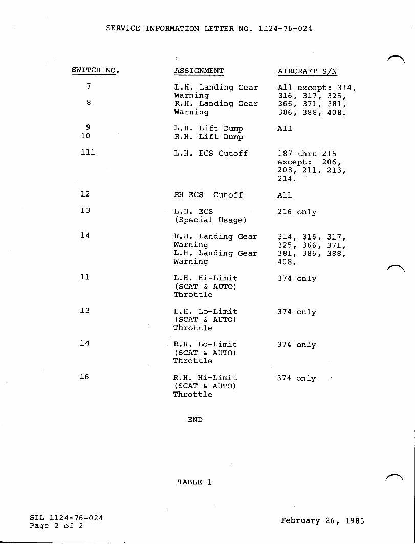
SERVICE INFORMATION LETTER NO. IL24-76-024
SWITCH NO. ASSIGNMENT AIRCRAFT S/N
L.H. Landing Gear A11 except: 3L4,Warning 316, 3L7 , 325,R.H. Landing Gear 366, 37I, 381,Warning 386, 388, 409.
7
8
910
111
L2
13
L4
11
srl., II24-76-024Page 2 of 2
13
L.H. Lift Dump AllR.H. Lift, Dump
L.H. ECS Cutoff 187 thru 215except z 206,209, 2LI, 2L3,2I4.
RH ECS Cutoff AllL.H. ECS(Special Usage)
2L6 only
R.H. Landing Gear 3l-4, 316, 3L7,Warning 325, 365 , 37I,L.H. Landing Gear 381, 386, 388,Warning 40 8.
L.H. Hi-Limit 374 only(SCAT & AUTO)Throttle
L.H. Lo-Limit 374 only(SCAT & AUTO)Throttle
R.H. Lo-Limit 374 only(SCAT & AUTO)Throttle
R.H. Hi-Limit 374 only(SCAT & AUTO)Throttle
END
L4
16
rABLE 1
February 26, 1985
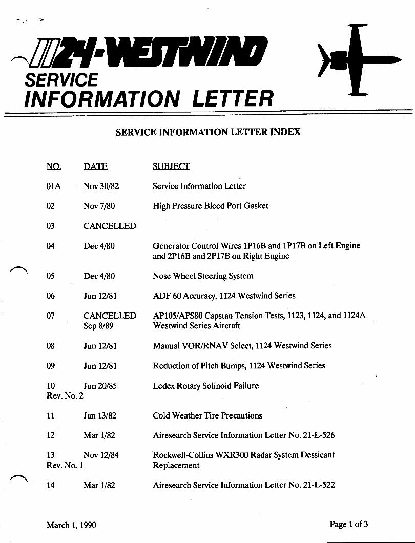
^trilTTSERVICEINFORMATION LETTER
NO.
01A
02
03
M
05
06
07
08
09
10Rev. No.2
NATF
Nov 30/82
Nov 7/80
CANCELLED
Dec 4/80
Dec 4/80
Jun 12181
CANCELLEDSep 8/89
Jun 12181
Jun 12181
Jun 20185
SERVICE INTORMATION LETTER INDEX
SI iRIFCT
Service Information Letter
High Pressure Bleed Port Gasket
Generator Control Wires 1P168 and 1P178 on Left Engineand 2P16B and2PLTB on Right Engine
Nose Wheel Steering System
ADF 60 Accuracy,Il?A Westrrind Series
AP105/APS80 Capstan Tension Tests, L123, t124, and lL24AWestrvind Series Aircraft
Manual VOR/RNAV Select, 1124 Westrvind Series
Reduction of Pitch Bumps, 1124 Westwind Series
Irdex Rotary Solinoid Failure
Cold Weather Tire Precautions
Airesearch Service Information Irtter No. 2 1-L526
Rochvell-Collins W)R300 Radar System DessicantReplacement
Airesearch Service Information Irtter N a. 2l-l-522
11 Janl3l82
12 Mat U82
13 Nov 12184
Rev. No. 1
14 Mar U82
March 1, 1990 Page 1 of3
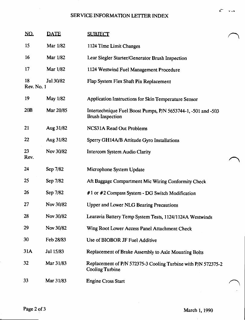
L r<+
SERVICE INFORMATION LETTER INDEX
NO. DATF SURIFCT
15 Mar U82 1124 Time Limit Changes
16 Mar ll82 L,ear Siegler Starter/Generator Brush Inspection
17 Mar tl82 1124 Westwind Fuel Management Procedure
18 Jul30/82 Flap System Flex Shaft Pin ReplacementRev. No. 1
19 May ll82 Application Instructions for Skin Temperature Sensor
208 Mar 20185 Intertechnique Fuel Boost Pumps, P/N 5653744-1, -501 and -503Brush Inspection
2L Aug3ll82 NCS31A Read Out Problems
22 Aug3ll82 Sperry GH14A/B Attitude Gyro Installations
23 Nov 30/82 Intercom Svstem Audio ClariwRev.
24 SepT/82 Microphone System Update
25 Sep7182 Aft Baggage Compartment Mic Wiring Conformity Check
26 Sep7l82 #l or #ZCompass System - DG Switch Modification
27 Nov 30/82 Upper and l.ower NL,G Bearing Precautions
28 Nov30/82 l*arawaBatteryTemp SystemTests, Ll24tll24{Westwinds
29 Nov30/82 Wing Root l.owerAccess Panel Attachment Check
30 Feb 28183 Use of BIOBOR JF Fuel Additive
31A Jul 15/83 Replacement of Brake Assembly to Axle Mounting Bolts
32 Mar3l/83 Replacementof PA.{ 572375-3CoolingTurbinewithP/N 572375-2CoolingTurbine
33 Mar 31/83 Engine Cross Start
Page2 of 3 March l,1990
1,. -t
SERVICE INFORMATION LETTER INDEX
NO. IIATE SITR.IFC.T
34 Apr 15/83 Intermittent Collins Rack Mount Connectors
35 CANCELLED Vibration I-evel for #2 AltimeterMay 22187
36 May 16/83 1124 Westwind Refrigeration Unit Installaltion
37 Jul 1/83 Emergency Exit Checks
38 Nov 30/83 Inspection and Service Life on Gas Storage Bottles P/N 3753015and 3753015-501
March 1, 1990 Page 3 of3
trfi{SERY'CE,NFORMAT'ON LETTER
S I L No. 01A November 30, L982(This Service Infornation Letter supercedes SIL No. 01, datedNovenber 7, 1980 in its entirety.)
The Service Information Letter is an official publicationof IAI/IAII and is a part of the Service Data Book. SILrsshould be retained as a perrnanent reference document.
Service Information Letters will transmit data of.an inform-ative nature only and should not be interpreted as data ap-proved by ICAA/FM or IAI Engineering. SIL's will adviseoperators of maintenance hints, verifications of systen con-figuration, announce approved changes in advance of formalpublication and transnit some vendor data.
/@Wrcwm!!r.n*
SUBSIOIAFY OF ISRAEL AIRCRAFT INOUSTRI€S. LTOBEN GURION AIBPORT. ISRA€L
Page I of I

til2lSERY'CE,NFORMAT'ON LETTER
Investigation of a reported ITT overlimit revealed high pressurebleed air leakage at the engine high pressure bleed port.
The leakage resulted from deterioration of a P/N 307tI1'7 gasket.This gasket is an AiResearch shipping gasket and is not suitablefor extended inservice use.
When an engine is returned from an AiResearch repair facility forreinstallation, or a Loaner Engine is installed, the shippinggasket should be removed and a gasket P/N F10A- 5-P20244-Lsinstalled on the high presj,tt" 6teed port.
Reference LL24 IPC, Chapter 71-00-00, Figure 5n Itern 33
SIL No. 02
SUBJECT: fIIGH PRESSURE BLEED PORT GASKET
/@lIIwtw"!!e**
NOVEMBER 7, 1980
SUESIDIARY OF ISRAEL AIRCRAFT INOUSTRIES. LTO8EN OURION AIRPORT. ISRA€L
Page 1 of 1
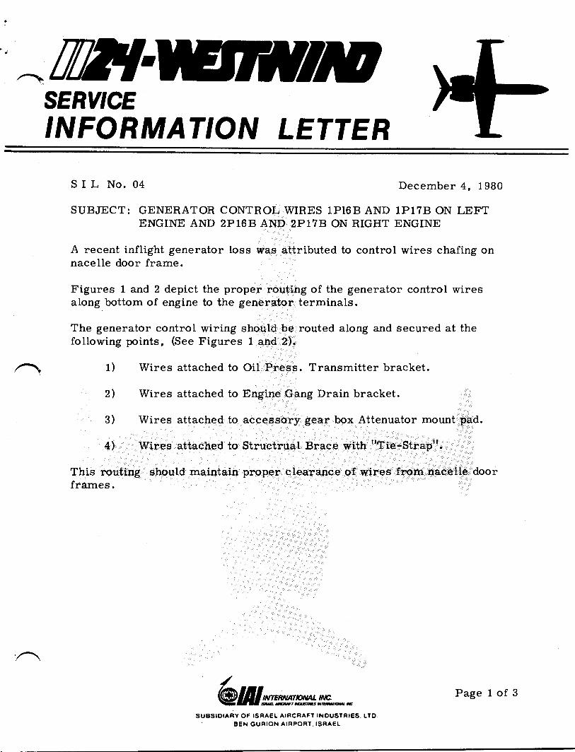
^ TWISERY'CE,NFORMAT'ON LETTER
^
S I L No. 04 December 4, 1980
SUBJECT: GENERATOR CONTROL WIRES 1PI6B AND 1P178 ON LEFTENGINE AND 2P168 AND 2P17E ON RIGHT ENGINE
A recent inflight generator loss was attributed to control wires chafing onnacelle door frame.
Figures I and 2 depict the proper routing of the generator control wiresalong bottom of engine to the generator terminals.
The generator control wiring should be routed along and secured at thefollowing points, (See Figures 1 and 2).
1) Wires attached to Oil Press. Transmitter bracket.
2l Wires attached to Engine Gang Drain bracket.
3) Wires attached to accessory gear box Attenuator mount pad.
4l Wires attached to Structrual Brace with "Tie-Strap".
This routing should maintain proper clearance of wires from nacelle doorframes.
@frlwwm**/
SUBSIOIARY OF ISRAEL AIRCNAFT INOUSTRIES. LTOAEN GURION AIRPORT. ISRAEL
Page 1 of 3
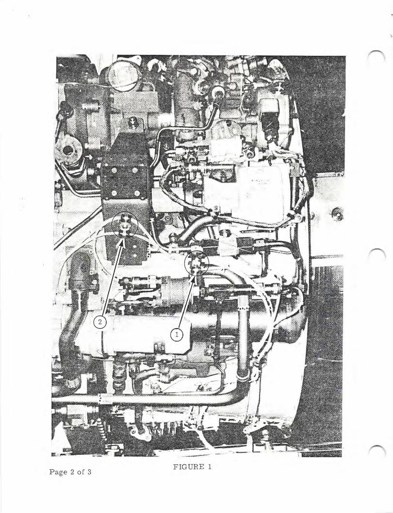
FiGURE 1Page 2 of 3
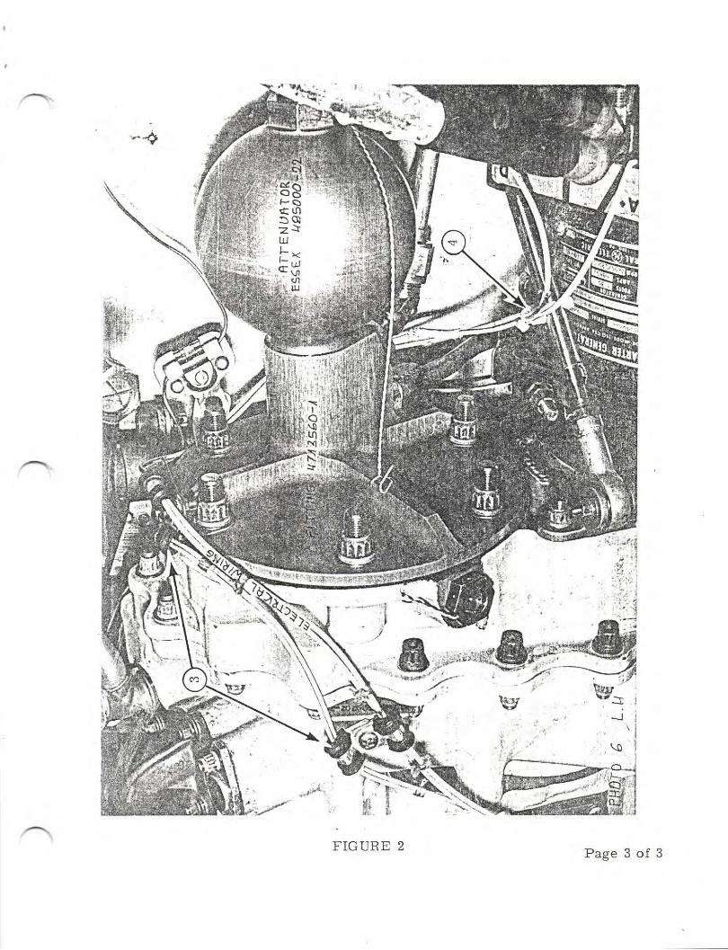
*+
FIGURE 2
}\*{
' '$i'g'-l>-'.et
Page 3 of 3
TW{SERY'CE,NFORMAT'ON LETTER
SIL No.05
SUBJECT: NOSE WHEEL STEERING SYSTEM
December 4, 1980
Investigation of reported "POPPINGtt noises coming from nose gear duringground taxi, revealed popping sounds were coming from nose steeringbrackets at radar bulkhead attach points, reference Figure 3, Chapter35-50-00, t124 IPC.
The attaching bolts (4 ea. AN4-10A) were not torqued down properLy. Referto Chapter 12-00-00, Page 10, lt24 Maintenance Manual for proper torquevalue for AN4 size bolts with MSZ0365 t;rye nuts, also assure adequatewashers are installed to prevent nuts from bottoming out on bolt shank.
/@Wwrwmn*
SUESIOIARY OF lSFAEL AIFCRAFT INOUSTRIES.. LTOBEN GURION AIRPORT. ISRAEL
Page 1 of 1
THSERY'CEINFORMAT'ON LETTER
S I L No. 06 June L2, 1981
SUBJECT: ADF 60 ACCURACY, LT24 WESTWIND SERIES
To provide greater ADF accuracy, those aircraft equipped with ADF 60syste_ms may wish to change the Quadrantal Error correction from 19oto 14o. This can be accomplished by removing the jumper between pins4 and 20, and adding two new Jumpers; one between pins 4 and 12, andthe other between pins 16 and 30,
The procedure described above applies only to the No. 1 ADF 60 in thoseaircraft with dual systems.
/@lIIwx,wmn*
SUESIOIARY OF ISRAEL AIRCRAFT INOUSTFIIES. LTO8EN GURION AIRPORT. ISRAEL
Page 1 of I
^trilI}SERY'CEINFORMATION LETTER
SERVICE INFORMATION LETTER NO. 07 September 8, 1989
SUBJECT: AP105/APS80 CAPSTAN TENSTON TESTS, 1123, 1124 1124AWESTWIND SERIES AIRCRAFT
CANCELLATION NOTICE
This service information letter is hereby cancelled. Theinformation contained in this service information letter has been
-,,'.-. revised and reissued in Service Information Letter No. 1124-22-/ \ 058.
June 12, 1981October 1 5' 1982September 8, 1 989
SILPage
No. 071of1Revision
Revi-sion1,2,
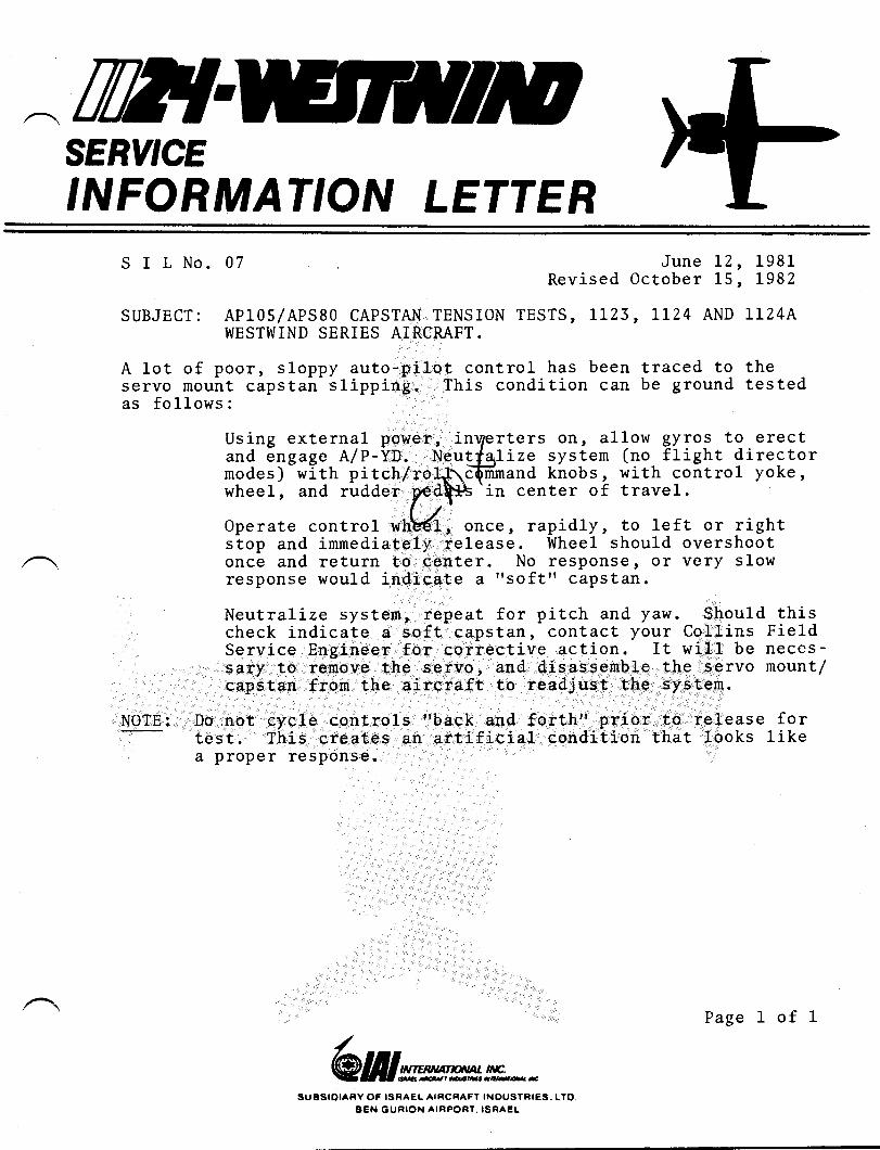
SERY'CE,NFORMAT'ON LETTER
S I L No. 07 June lZ, 1981Revised October 15, L98Z
SUBJECT: AP105/APS80 CAPSTAN TENSION TESTS, LLZ3, LLZ4 AND LL24AWESTWIND SERIES AIRCRAFT.
A lot of poor, sloppy auto-pilot control has been traced to theservo mount capstan slipping. This condition can be ground testedas follows:
NOTE:
Using external power, inrTerters otr, allow gyros to erectand engage A/P-YD. Neutt'qlize systern (no flight directormodes) with pitch/rol+\c@mand knobs , with control yoke,wheel, and rudder
ftt* t" center of travel.
Operate control wnHf , once, rapidly, to lef t or rightstop and immediately release. Wheel should overshootonce and return to center. No response, or very slowresponse would indicate a "soft" capstan.
Neutralize systen, repeat for pitch and yaw. Should thischeck indicate a soft capstan, contact your Collins FieldService Engineer for corrective action. It will be neccs-sary to remove the servo, and disassemble the servo mount/capstan from the aircraft to readjust the system.
Do not cycle cpntrols "back and forth" prior to release fortest. This creates an artificial condition that looks likea proper response.
/@Wwvwmn*
SUESIOIAFY OF ISRAEL AIRCRAFT INDUSTNIES,. LTO,BEN OURION AIRPORT. ISRAEL
Page 1 of 1
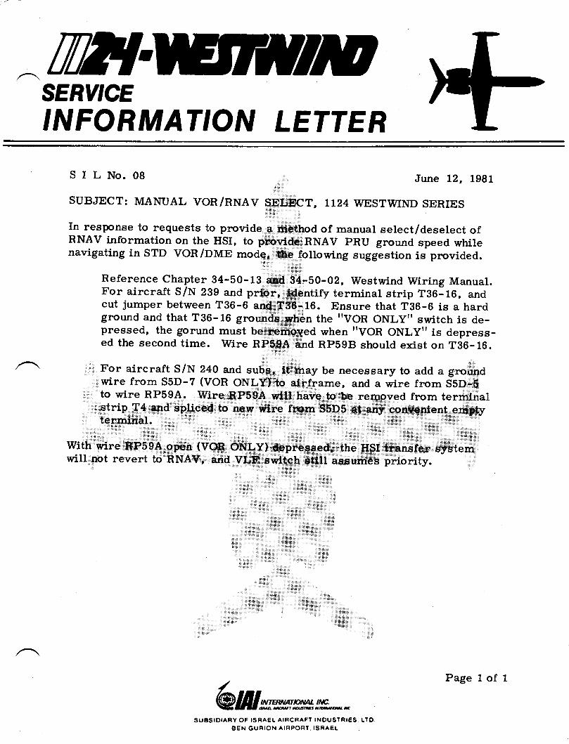
^TWTSERY'CEINFORMAT'ON LETTER
SILNo.08 June 12, 1981
SUBJECT: MANUAL VOR/NWEV SELECT, TI24 wESTwIND SERIES
In response to requests to provide a method of manual select/deselect ofRNAV information on the HSI, to provide RNAV PRU ground speed whilenavigating in STD VOn /DME mode, thi fottowing suggestion is provided.
Reference Chapter 34-50-tS and 34-50-02, Westwind Wiring Manual.For aircraft S/N 239 and prioi, identify terminal strip Tg6:16, andcut jumper between T36-6 and T36-16. Ensure that T36-6 is a hardground and that T36- 16 grounds when the "VOR ONLY" switch is de-pressed, the gorund must be removed whenttVOR ONLYT'is depress-ed the second time. Wire RP59A and RP59B should exist on T36-16.
For aircraft S/N 240 and subs, it may be necessary to add a groundwire from S5D-7 (VOR ONLY) to airframe, and a wire from S5D-Fto wir_e RP59A. Wire RP59A will have to be removed from terminalstrip-T4 and spliced to new wire frcm S5D5 at any convenient emptyterminal
wit-h wire RP59A open (voR oNLy) depressed, the HSI tranefer systemwill not revert to RNAv, and vLF switch still assumes priority.
/@Wrcwmm**
SUBSIOTARY OF ISRAEL AIFICRAFT INOUSTRIES, LTOBEN GURION AIRPORT, ISNAEL
Page I of 1
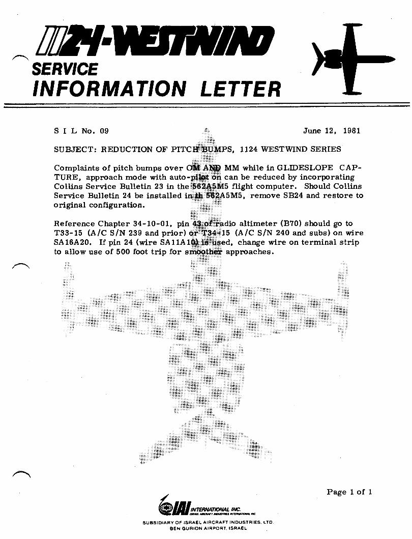
ilI{SERY'CE
'NFORMAT'ON LETTER
SILNo.09 June 12, 1981
SUBJECT: REDUCTION OF PITCH BUMPS, 1124 WESTWIND SERIES
Complaints of pitch bumps over OM AIID MM while in GLIDESLOPE CAP-TURE, approach mode with auto-pf,lot on can be reduced by incorporatingCol.lins Senrice Bulletin 23 in the 562ASM5 flight computer. Should CollinsService Bulletin 24 be installed in th 562A5M5, remove SB24 and restore tooriginal configuration.
Reference Chapter 34-10-01, pin 43 of radio altimeter (B?0) should go toT33-15 (A/C S/N 239 and prior) or T34-15 (A/C S/N 240 and subs) on wireSA16.A20. If pin 24 (wire SA11A10) is used, change wire on terminal stripto allow use of 500 foot trip for smoother approaches.
/@lIIrcxrwm**
SUBSIDIAFY OF ISFAEL AIRCFIAFT INDUSTRIES. LTOBEN GURTON AIRPORT. ISRAEL
Page 1 of 1
w
SERVICE PUBLICATloNS
revision noticeSIL NO. 10 (Revision 2l
SUBiIECT: LEDEX ROTARY SOLENOTD FATLURE
r.Iune 20, 1985
REASON TORREVISION: To add a suitabLe eqbstitute to p/l 187408-001.
After PAI 187408-00I add the word 'or" andPAr 189151-001.
Tfln'AUU,|LJG,t)raragtta''I'amr:gU'SIOIAFV OF |!EAGL AIRCNAfI TNOUETNICE. LTO
BCX OUnION ArtPOet. tgeACL
Page L of, I
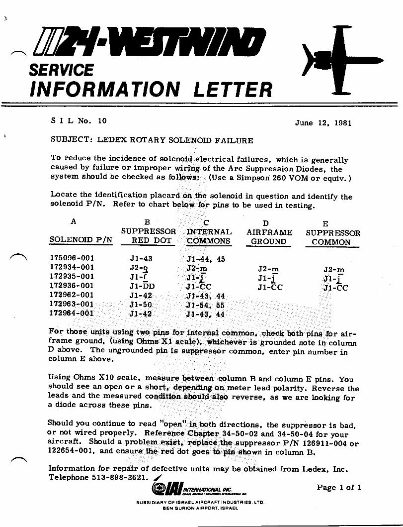
TW{SERY'CE,NFORMAT'ON LETTER
SILNo. l0 June 12, 1981
SUBJECT: LEDEX ROTARY SOLENOID FAILURE
To reduce the incidence of solenoid electricar failures, which is generallycaused by failure or impnoper wiring of the Arc Suppression Diodes, thesystem should be checked as followe: (Use a Simpson 260 VOM or equiv. )
Locate the identification placard on the solenoid in question and identify thesolenoid P/N. Refer to chart below for pins to be used in testing.
BA cINTERNALCOILIMONS
DAIRFRAME
GROUND
ESUPPRESSOR
COMMONSUPPNESSOR
SOLENOTD P/N RED DOT
J1-43J2-gJ1-fJl-bDJt-42J1-50J1-42
J2-mJl-iJ1-CC
J2-mJr-i-.lr-*cc
1?5096-001t72934-OOll?2935-0011?2936-001172962-0011?2963-001t?2964-001
Jt-44, 45J2-lgJl-j-Jt-ccJ1-43, 44Jt-54, 55Jt-43, 44
For those units using two pins for internal common, check both pins for air-frame ground, (using Ohms Xl scale), whichever is grounded note in columnD above. The ungrounded pin is euppreseor common, enter pin number incolumn E above.
Using Ohms X10 scale, measure between column B and column E pins. youshould see an open or a short, depending on meter lead polarity. Reverse theleads and the measured condition should also reverse, as we are looking fora diode across these pins.
Should ;rou continue to read ttopentt in both directions, the suppressor is bad,or not wired prnoperly. Reference Chapter 34-50-02 and 34-50-04 for youraircraft. should a problem exist, replace the suppressor p/N 126911-004 or122654-001, and ensure the red dot goes to pin shown in column B.
Information for repair of defective units may be obtained fr.om Ledex, Inc.Telephone 5 13-898-3621. 1/
@lfllwrmm**SU6SIOIARY OF ISNAEL AIRCRAFY INDUSTRIES.. LTO
BEN GURION AIRPORT. ISRAEL
Page I of I
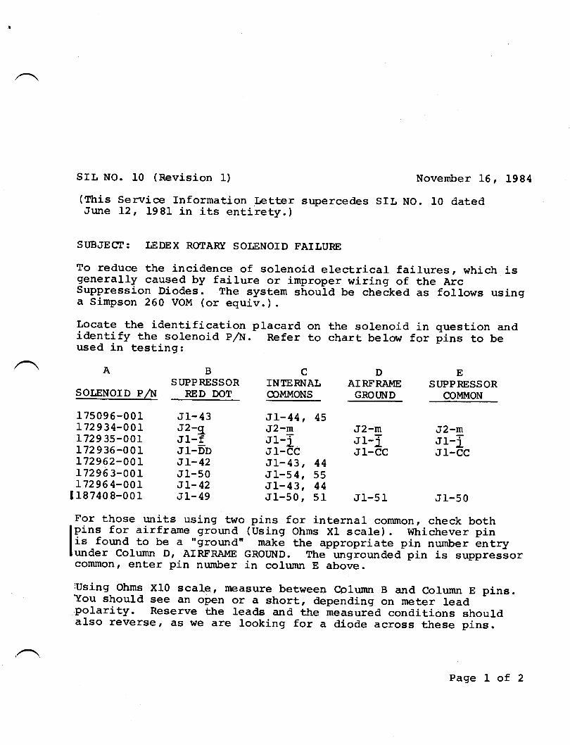
SIL NO. 10 (Revision 1)
(Ttris Service Information LetterJune L2, 1981 in its entirety.)
November L6, 1984
supercedes SIL NO. I0 dated
SUBJECI: LEDEX ROIARY SOIJENOID FAIIURE
To reduce the incidence of solenoid electrical failures, which isgenerally caused by failure or improper wiring of the ArcSuppression Diodes. The system should be checked as follows usinga Simpson 260 VOM (or equiv. ) .
Locate the identification placard on the solenoid in question andidentify the solenoid p,/lil. Refer to chart below tor fins to beused in testing:
A
SOI,ENOID P^iI
175096-001 .t1-43L72934-001 J2-gL729 3s-001 Jl-f172936-001 JI-DD172962-00r JL-42L72963-001 J1-50172964-001 JL-42
1187408-001 JI-49
ST'PPRESSOR INTERNAI.,RED DOT @MIT{ONS
AIRFRAIUE ST'PPRESSORGROT]ND COMMON
JI-44 , 45J2-m J2-mr1-I r1-fJI-CC JI-CCJI-43, 44JL-s4, 55J1-43, 44J1-50r 51 J1-51
J2-mJ1-TJ1-CC
J1-50
For those r:nits using two pins for internal common, check bothlpi"q for airframe ground (-Using Ohms XI scale). Whichever pinli"-found to be a "ground" make the appropriate pin number LntryJunder Column D, AIFFRAME GROUND. The r:ngrounded pin is suppressorconmon, enter pin number in column E above
:Using Ohms X10 scale r measure betwee4 Cplurnn B and Column E pins.You should see an open or a short, depending on meter lead.polarity. Reserve the leads and ttre measured conditions shouldalso reverse, as we are looking for a diode across these pins.
Page I of 2
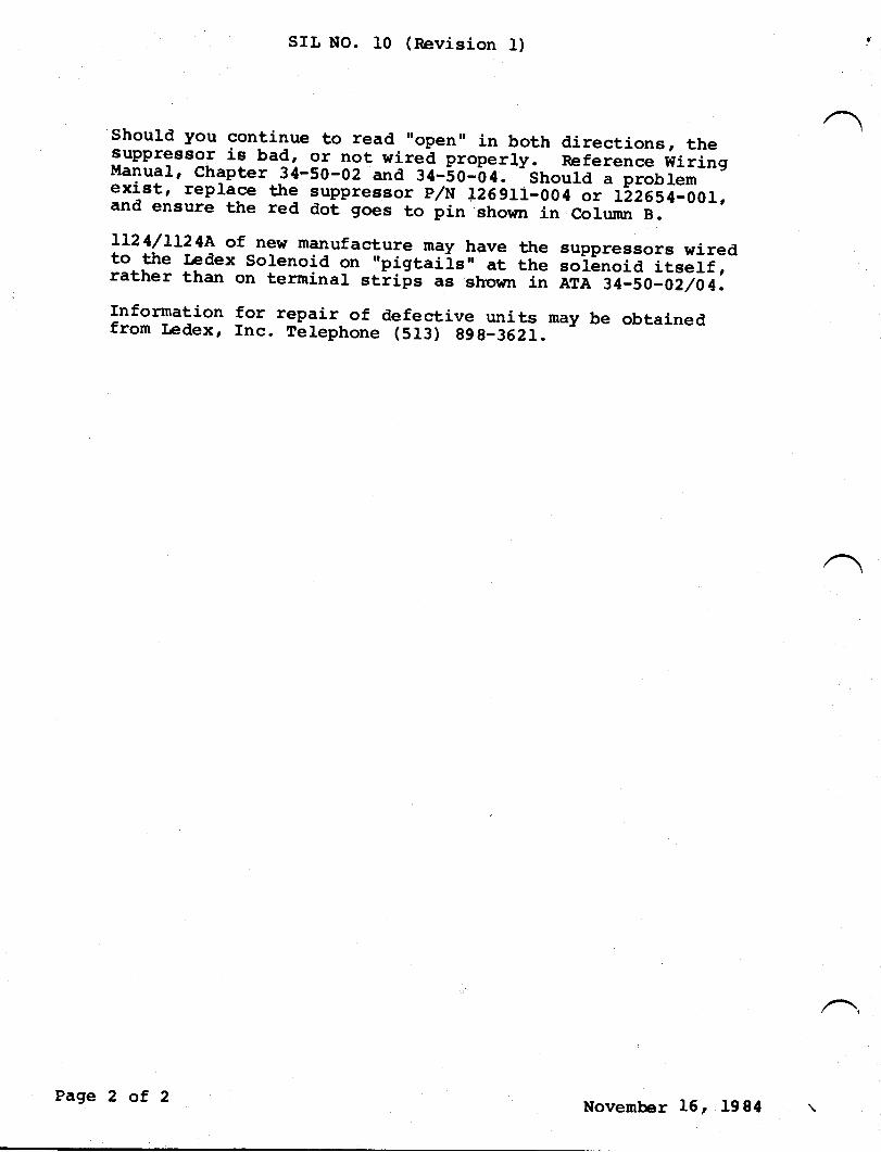
SIL NO. 10 (nevision 1)
should you continue to read ',open, in both directions, thesupPressor is bad, or not rirg4 plopqrly. Reference WiringManuar, chapter 3{-50-02 and gl--so-b4.-'should a fi"nr.*exi_st, replace the :uppressor p/N risirr-004 or t2zase-oot,and ensure the red dol- goes to pin srrown i" -c"i,-i-gl
LL24/LL2{A of new manufacture may have ttre suppressors wiredto the redex solenoid on "pigtaiis" at ihe soilnoia itself,rather than on terminal stlips as shown in ATA il:so-oz /04.rnformation for repair of defective units may be obtainedfrom ledex, Inc. Telephone (513) egg-362f .
Page 2 of 2 November 162 198{ \
!-*,,
TTT{SERY'CEINFORMATION LETTER
S I L No. lt
SUBJECT: CoLd Weather Tire Precautions
January 13, 1982
With the advent of colder weather, several cases of rapid tire pressure losshave been experienced on the ModelLL24 main tires. This has been a reoccur-ring problem in cold weather operation.
Goodyear Aerospace has extensively tested a wheel and tire which had exper-ienced this rapid pressure loss, but were unable to duplicate the rapid pres-sure loss. However, leakage w'as experienced through the wheel O-ringpacking during simulated taxi at -55oF, and a new O-ring packing has beendesigned whichrshould be available for field testing in early February.
Since it has not'been possible to duplicate the rapid tire pressure loss undercontrolled conditions, we suggest the following precautions be taken whenoperations are considered into or out of an area where the ambient temper-ature is below 10oF:
Insure that tires and wheels are installed and assembledin accordance with Goodyear Aerospace Manual AP-446 orChapter 32-40-00 of the Modet Ll24lIl24A MaintenanceManual. Particular attention should be given to inspectionof the wheel O-ring packing, adequate greasing of the O-ringprior to installation, liberal appl,ication of Lubtork to thewheel assembly bolts, washers and nuts (see GoodyearGS-SL-Il), and torquing of the bolts to the proper value.
Until new wheel O-ring packings have been tested and madeavailable by Goodyear, it is recommended that MS902L-268O-rings, manufactured by Parker Seal Co. be used whenavailabie. The Parker O-rings have better cold tempera-ture characteristics than some other seals whicrr- also meetMS902t-268. The thickness of any new O-ring packingshould be checked before installation on the wheel. Mini-mum thickness is 0.135 inch.
@ lil vrxsp*t* !,!#;,^.,,*
SUBSIDIARY OF ISRAEL AIRCRAFT INDUSTRIES, LTD.
BEN GURION AIRPORT, ISRAEL
I.
2.
/Page I of 3
SERVICE INFORMATION LETTER No. tl
The allowed leakage rate of a mounted and inflated tire is sTo orapproximately 8 psi in 24 hours. Also, tire pressure will fluctuatewith temperature. For each 5oF of temperature change the tirepressure will change approximately 1.5 psi. For these reasons,TIRE PRESSURE sHouLD BE CHECKED DAILY. If large tempera-ture changes are to be encountered, then tire pressure should beserviced prior to each flight. when operations are to be madefrom a moderate temperature to a colder temperature, then tirepressure should be adjusted so that the pressure upon arrival willbe approximately 140 psi. use Figure I as a guide to adjust tirepressure to maintain a minimum of 140 psi. After returning tomoderate temperatures, tire pressure should be reduced to therecommended pressure of 155 psi.
Goodyear recommends a maximum tire pressure of 166 psi beobserved, however in some cases it may be necessary to exceedthis value to insure adequate tire pressure upon arrival at a desti-nation where very cold ambient temperatures are expected. Beadvised that operations with tire pressures in excess of 166 psiwill tend to reduce wheel and bolt life, depending on gross weightand taxi distances.
5. If the airplane has set for some time, it is recommended that theairpiane be moved off the "flat spots" on the tires before tirepressure is checked.
6. After servicing tires, leak check valve core, then replace highpressure valve stem cap.
If you experience rapid tire pressure loss; please complete the enclosedquestionnaire and forward it to IAI International, Oklahoma City, OK. Thiswill help us determine the extent of the problem and will assist in the resolu-tion.
3.
-
4.
Page 2 of 3 Janl 82
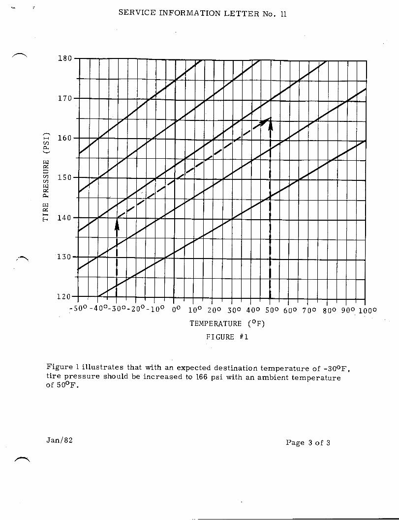
180
L70
,,\ 130
SERVICE INFORMATION LETTER No. II
I 160CN
rtl
q 150v)rr1
rrl
I 140
L20-50o-40o-j0o-Z0o_10o go 10o Z0o S0o 40o 50o 600 T0o g0o 90o 10
TEMPEMTURE (oF)
FIGURE #I
Figure l illustrates that with an expected destination temperature of -30oF,tire pressure should be increased to 166 psi with an ambient temperatureof 50oF.
0o
//
//
a
//
a
-t/
// a
/a
/ /
//
//
// -
//
/ 7 /
//
/ /a
/ / /
/a
//
/
/ a /
/
/
Jan I 82 Page 3 of 3
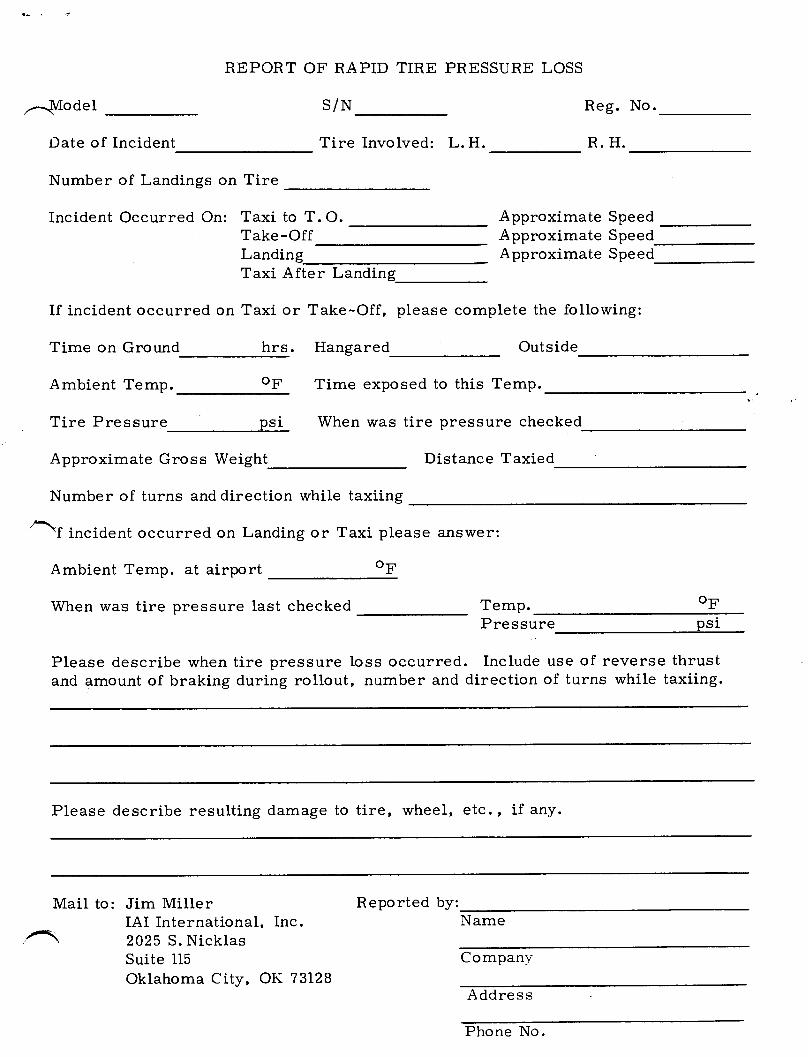
--\tlodelDate of Incident
Number of Landings on Tire
Incident Occurred On: Taxi to T. O.Take-OffLanding
REPORT OF RAPID TIRE PRESSURE LOSS
S/N
Tire Involved: L. H.
Reg. No.
R. H.
Approximate SpeedApproximate SpeedApproximate Speed
Taxi After Landing
If incident occurred on Taxi or Take-Off, please complete the following:
Time on Ground hrs. Hangared Outside
Ambient Temp. op Time exposed to this Temp.
Tire Pressure psi When was tire pressure checked
Approximate Gross Weight Distance Taxied
Number of turns and direction while taxiing
\f incident occurred on Landing or Taxi please answer:
Ambient Temp. at airport op
When was tire pressure last checked Temp. opPressure psi
Please describe when tire pressure loss occurred. Include use of reverse thrustand amount of braking during rollout, number and direction of turns while taxiing.
Please describe resulting damage to tire, wheel, etc., if any.
Mail to: Jim MillerIAI International, Inc.2025 S. NicklasSuite II5Oklahoma City, OK 73128
Name
Company
A ddres s
Reported by:
Phone No.
I
^ xilE{SERY'CE,NFORMAT'ON LETTER
Attached you will find a copy of AiResearch Service lnformation Letter No.21-L-525. This AiResearch publication covers oil 'change procedures forrefrigeration units instal led in 112& Westwind series ai rcraft. lA1 |
concurs with the procedures set forth in Airesearch slL No. 2l-L-526.
SIL No. 12
SUBJECT: AIRESEARCH SERVICE INF0RMATl0N LETTER NO. 21-L-526
/@lIIrcwmmn*
SUBSIDIAFY OF ISRA€L AIRCRAFT INOUSTNI€S. LTDBEN GURION AIRPORT. ISRAEL
March I , 1982
Page I of I
TO:
SUBJECT:
REFERENCE:
AIRESEARGH MANUFACTURING GOMPANY OF CALIFORNIAA OI\,ITION OF THE OAITCT' COIPORATION
2525 w€AT tgOT|t STFE€T r TOpRANtr€, CALtFOpNTA 90SO9r€LEPHONE: (Zr3] 323.95OO.32I.5OOO O CAEL€: GAF|rlE'TAIFI TORF|ANCE
s.I.L. 2t-L-526December 7, 1981Page I of I
SERVICE INFORMATION LETTER
All 1124 Westwind 0perators
Recormended 0il Change Procedure for P/N 572375, CoolingTurbine Used in PlN 220A165, Refrigeration Unit
0perations and Maintenance Instructions 4-272
Examinations of turbines returned from the field indicate that higher thandesired operating temperatures occur during some flight and ambient conditions.The high temperatures contribute to carbon formation in the lubricating oil,which hinders the oil flow to the bearings. This restriction in flow reducesthe lubrication at the bearing and can increase bearing wear and reduceturbine I ife.
AiResearch recormends that at the normal oil check period, the oil should bedrained through the drain port on the bottom of the turbine, and fresh oiladded to the top of the fill port per the referenced manual.
The referenced manual will be revised to incorporate this procedure.
Ernie MillerCustomer Service Engineer
APPROVED:
Preston G. H6llandManager, Field Service
sYSlcM9 NO COxPONExTS rOF: aaro.F^cc, cLSctaoxrc, otouNo tlaxarol?a?toi. xattxc xucLCAt axo lLout"ataL lrrltcatroNS
t
SERY'CE,NFORMAT'ON LETTER
SIL NO. 13 (Rev. 1)
lfnis Service Information Letter supercedesMarch l, L982 in its entirety ).
November 12, 1984
SIL NO. 13 dated
SUBJECT: ROCKWELL-COLLINS WXR300 RADAR SYSTEI4 DESSICAtiITREPLACEI4ENT.
SU6SIOIAFY OF ISRA€L AIFCNAFT INOUSTRIES, LTDB€N GUNION AIRPOFT. ISRAEL
A11 aircraft equipped with the Rockwell-Collins WXR300 RadarSystem have a crystal dessicant bottle installed on a shelf inthe right nose compartment.
The dessicant bottle should be checked frequently to determine ifit is still effective. A color comparison chart is affixed tothe bottle to assist in ttris check. Shou1d the crystal colorindicate replacement is required, a dessicant refi11 is available
lfrom any Rockwell-Collins dealer by ordering p/N 013-1399*020.
In the event it becomes necessary to replace the dessicant bottle,a complete plastic dessicat,or assembly may be obtained by
lordering Rockwell-Colline P/l{ 013-1399-010. The plasticdessicator assembly includes one refill and is also availablefrom any Rockwetl-Collins dealer.
/@lIIwtw!!&n* Page 1 of I
^TT]TSERY'CE,NFORMAT'ON LETTER
S I L NO. 13 MARCH 1, 1982
SUBJECT: ROCKWELL-COLLINS WXR3OO RADAR SYSTEM DESSICANTREPLACEMENT.
SUASIDIARY OF ISRAEL AIRCRAFT INOUSTRIES.. LTOBEN GUFIION AIRPORT, ISRAEL
AII aircraft equipped with the Rockwelt-Collins WXR300 Radar System havea crystal dessicant bottle installed on a shelf in the right nose compartment.
The dessicant bottle should be checked frequently to determine if it is stilleffective. A color comparison ehart is affixed to the bottle to assist in thischeck. Should the crystal color indicate replacement is required, a dessicantrefill is available from any Rockwell-Collins dealer by ordering P/N 01399-020.
In the event it becomes necessary to replace the dessicant bottle, a completeplastic dessicator assembly may be obtained by ordering Rockwell-CollinsP/N 13-1399-010. The plastic dessicator assembly includes one refill and isalso available from any Rockwell-Collins dealer.
/@lillwm
Page I of I
..,
^ Til27SERY'CE,NFORMAT'ON LETTER
SILNO. L4 MARCH I, I9B2
SUBJECT: AIRESEARCH SERVICE INFORMATION LETTER NO. 2I.L-522
Attached you will find a copy of AiResearch Service Information Letter No.2l-L'522. This AiResearch publication covers P/N 188682-l Heat Exchangerinspection and cleaning. These heat exchangers are part of the 1124 Westwindseries refrigeration units. IAII recommends that each operator establish in-spection intervals to suit his location and type of operation to obtain optimumservice from the refrigeration unit.
/@lflfiwmm**
SUESIDIANY OF ISRA€L AIRCRAFT INOUSTRIES.. LTOBEN OUNION AIFIPORT. ISRAEL
Page I of 1
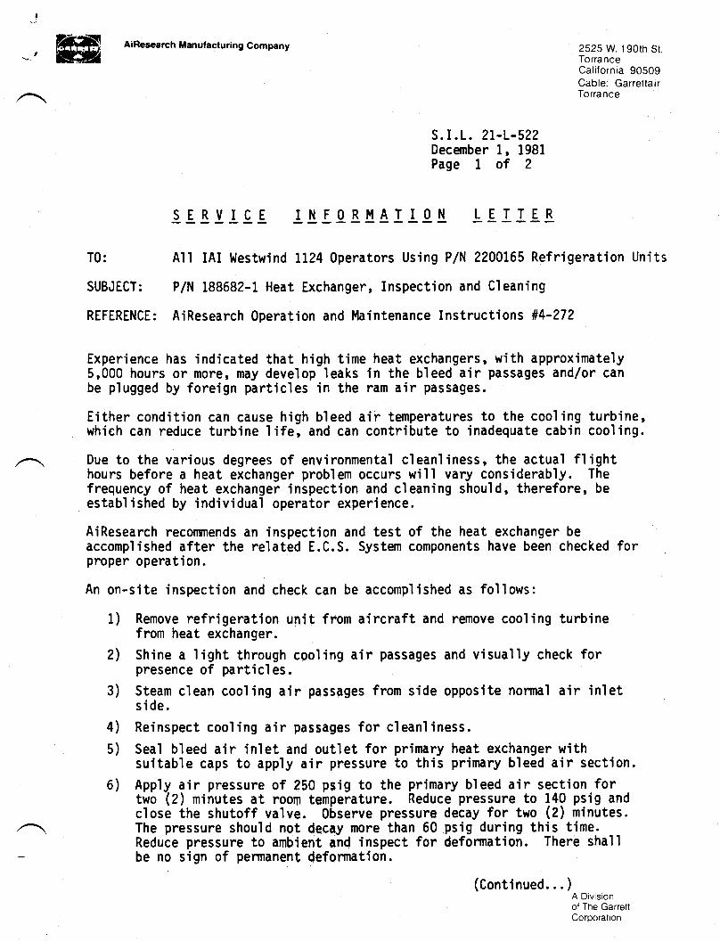
ffitHU ' EHIZ
AiRescarch Manufacturing Company 2525 W.190rh SrTorranceCalifornia 90509Cable: GarretlairTorrance
!E8JJ-!-E
s.I.L. 2t-L-522December 1, 1981Page I of 2
rI[!BTAIT9.!. LEIIE!T0: All IAI }{estwind 1124 0perators Using PlN 2200165 Refrigeration Units
SUBJECT: P/N 188682-1 Heat Exchanger, Inspection and Cleaning
REFERENCE: AiResearch 0peration and Maintenance Instructi ons #4-272
Experience has indicated that high time heat exchangers, v,,ith approximately5,000 hours or more, fiay develop leaks in the bleed air passages and/or canbe plugged by foreign particles in the ram air passages.
Either condition can cause high bleed air temperatures to the cooling turbine,which can reduce turbine'life, and can contribute to inadequate cabin cooling.
Due to the various degrees of environmenta'l cleanliness, the actual flighthours before a heat exchanger problem occurs will vary considerably. Thefrequency of heat exchanger inspection and cleaning should, therefore, beestablished by individual operator experience.
AiResearch recorrnends an inspection and test of the heat exchanger beaccomplished after the related E.C.S. System components have been checked forproper operation.
An on-site inspection and check can be accomplished as follows:
1) Remove refrigeration unit from aircraft and remove cooling turbinefrom heat exchanger.
2) Shine a light through cooling air passages and visually check forpresence of particles.
3) Steam clean cooling air passages from side opposite normal air inletside.
4) Reinspect cooling air passages for cleanliness.5) Seal bleed air inlet and outlet for primary heat exchanger with
suitable caps to apply air pressure to this primary bleed air section,6) App'ly air pressure of 250 psig to the primary bleed air section for
two (2) minutes at room temperature. Reduce pressure to 140 psig andclose the shutoff valve. 0bserve pressure decay for two (2) minutes.The pressure should not decay more than 50 psig during this time.
_
Reduce pressure to ambient and inspect for deformation. There sha'llbe no sign of pennanent deformation.
A Divisionof The GarrettCorporation
(Continued. . . )
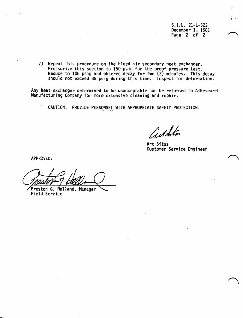
s.I.L. 2t-L-522December 1, 1981Page 2 of 2
7) Repeat this procedure on the bleed air secondary heat exchanger.Pressurize this section to 150 psig for the proof pressure test.Reduce to 105 psig and observe decay for two (2) minutes. This decayshould not exceed 35 psig during this time. Inspect for deformation.
Any heat exchanger determined to be unacceptable can be returned to AiResearchl'lanufacturing Company for more extensive cleaning and repair.
CAUTION: PROVIDE PERSINNET, WITH APPROPRIATE SAFETY PROTECTION.
tukArt SitasCustomer Service Engineer
APPROVED:
lland, ManagerField Service
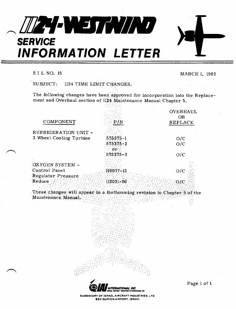
^trWTSERY'CE,NFORMAT'ON LETTER
SILNO. 15
SUBJECT: IT24 TIME LIMIT CHANGES.
The following changes have been approved forment and Overhaul section of 1124 Maintenance
MARCH I, T982
incorporation into the Replace-Manual Chapter 5.
OVERHAULOR
NEPLACECOMPONENT
REFRIGERATION UNIT -3 Wheel Cooling Turbine
OD(YGEN SYSTEM .Control PanelRegulator PressureReduce
These changes will appear inMaintenance Manual.
5753?5-l575375-2
or5753?5-3
n90??-t2
112031-06
a forthcoming revision to
o/co/c
alc
olc
olc
Chapter 5 of the
/@frlwmm**
SUASIDIARV OF ISRAEL AIRCRAFT INOUSTFIES.. LTOBEN GURION AIRPORT. ISRAEI
Page 1 of I
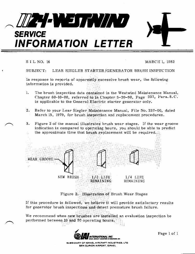
TilTTSERY'CE,NFORMAT'ON LETTER
SILNO. 16 MARC H I, 1982
SUBJECT: LEAR SIEGLER STARTER/CPNPNETOR BRUSH INSPECTION
In response to reports of apparently excessive brush wear, the followinginformation is provided.
1. The brush inspection data contained in the Westwind Maintenance Manual,Chapter 80-IO-00, referred to in Chapter 5-20-00, Page 237, Para.8.C.is applicable to the General Electric starter generator only.
2.
3.
WEAR GROOVE
Refer to your Lear Siegler Maintenance Manual, File No. 237-00, datedMarch 15, 1979, for brush inspection and replacement procedures.
Figure 2 of the manual illustrates brush wear stages. If the wear grooveindication is compared to operating hours, /ou should be ab[e to predictthe approximate time that brueh replacement will be required.
NEW BRUSH
SUBSIOIARY OF ISNAEL AIRCRAFT INOUSTRIES,. LTOB€N GURION AIRPORT. ISRAEI
Ll2 LrFEREMAINING
r/ 4 LrFERE}TAI N I NG
Figure 2. Illustration of Brush Wear Stages
If this procedure is followed, we beLieve it wiII provide satisfactory resultsfor generator brush inspections end detect premature brush failure.
We recommend when new brqehes are installed an evaluation inspection beperformed between 10 and 20 operating hours.
/@lIIw,wm** Page I of I
nflSERY'CE
'NFORMAT'ON LETTER
S I L NO. T7 MARCH 1, 1982
SUBJECTz LI24 WESTWIND FUEL MANAGEMENT PROCEDURE.
It is possible for fuel to be pumped overboard thru the fuselage fuel ventdrain line after filling all tanks. This can occur if fueling is accomplishedwith electrical power ON and some fuel is introduced or left in the tip tanks.
This subject was covered in the August and September 1981 Westwind Com-municators. A change has been made in the II24A Airplane Flight Manualrequiring the EXT PWR and BATTERY MASTER switches to be CYCLEDOFF and ON during the PRE-START sequence. A similar change will bemade to the 1124 Airplane Flight Manual.
If you must fuel the aircraft with electrical power ON (which IAII does notrecommend), and do not want to cycle the EXT PWR and BATTERY MASTERswitches OFF and ON, then it is possible to release the holding circuit of theAutomatic Transfer Relay by pulling and resetting the Automatic Transfercircuit breaker.
/@lillw,wmn*
SUEISIOIAFY OF ISRA€L AIRCRAFY INOUSTRIES.. LTO8EN GURION AIRPORT. ISRAEL
Page I of I
ffiI{SERY'CEINFORMAT'ON LETTER
SILNO.18REVISION NO. 1
This revision superceeds S I L N0. 18,entirety.
JULY 30, 1982
dated March 1, 1982 in its
SUBJECT: FLAP SYSTEM FLEX SHAFT PIN REPLACEMENT.
Groove pins have replaced ro11 pins on some flap systen flex shaftsP/N 193545-501 and -505 where the spline collar attaches at the in-board end. This has made conpliance with Service Letter No. WW-2424difficult. It is reconmended that grooved pins be replaced withro11 pins P/N MS9047-L}L or MS9048-101 at time of next relubrication.Pin replacenent may be accomplished as follows:
1. Remove flex shaft fron aircraft.2. Grind or file off peened end of pin.
3. Drive out pin with pin punch.
4. Comply with S/L WW- 2424 reinstalling new ro11 pin during flexshaft reassembly.
NOTE
Hole dimension for both -f01 pins must be.I25 to .LZg inch diameter. If hole dimen-sion exceeds these linits it may be reamedto .156 to .160 and an oversize ro11 pinIUS9047-L32 or MS9048-132 should be installed.
/@lIIwwmn*
SUESIDIARY OF ISRAEL AIRCRAFT INOUSTRIES, LTOBEN GUNION AIRPORT. ISRA€L
Page I of 1

IWTSERY'CE,NFORMAT'ON LETTER
S I L No. 19 May 1, 1982
SUBJECT: APPLICATION INSTRUCTIONS FOR SKIN TEMPERATURESENSOR.
Skin sensor should be applied to applicable surface at temperature above50o. The sensor and skin surface must be dry and free from contamination.
1. Clean sensor mating surface and skin with MEK to remove any oldadhesive or other contamination.
Apply transfer tape Scotch No. 467 to the sensor mating surface.
Remove adhesive protective liner and position skin sensor in desiredlocation. Exert a uniform and firm hand pressure to ensure completecontact.
2.
3.
/@lillww
SUBSIOIARY OF ISRAEL AIRCRAFT INOUSTFIES, LTOBEN GUNION AIRPOR'. ISRAEL
Page I of I
TW{SERY'CE,NFORMAT'ON LETTER
Ivlarch 20, 1985SIL NO. 2OB
fhis SIL supersedes SIL No.20At dated February Lt 1984 in itsentirety.
SUBJECT: TNTERTECHNTeUE FUEL Boosr puMps, P/N 5653744-Lt 50rAND -503 BRUSH INSPECTION
Brush replacement and overhauL of the pumps have been changedto t'On Condition.rr
It is recommended that operators continue to keep track of theactual operating time on the main and alternate pumps. Aircraftoperating time may not be an accurate record of pump operatingtime especial-Iy with regard to the alternate pump.
Brush inspection requires removal of the pump from the aircraftand partial disassembly. After inspection, the pump isreassembled with a new seal. The pump must then be leak checked.The leak check can only be accomplished by an authorized overhaulagency.
Brush replacement and pump overhaul requirements in Chapter 5 ofthe Maintenance Manual wiLl be changed to "On Conditionn andChapter 28 procedures witl be updated to reflect those changesin the next revision of the LL24/LL24A itlaintenance ltlanual.
/@lfilwwm**
SUgSIOIARY OF ISRAEL AIRCRAFT INOUSTRIES,. LTO,BEN GURION AIRPOBT. ISRAEL
Page I of I
TW{SERY'CEINFORMATION LETTER
S I L NO. 2L
SUBJECT: NCSSIA READ OUT PROBLEMS
Several problens have beenCold turn on errors, readselector changes are made.aircraft equipped with thesupply used in the NCS31A
encountered with theout blinking or going
These problens occurCollins 659U-1 logic
sys ten.
AUGUST 51, 1982
NCSS1A system.blank when HSIonly in those
and lighting power
be reduced or elin-
1.
2.
By acconplishing the following, the problens mayinated:
Visually check relays RL75, RL89, RL90, RL91, RL93, and RL120for a 1N645 diode nounted across Xl and XZ terninals of eachreLay. Reference Wiring Manual pages 34-50-07, and 34-50-04effective on your aircraft.If diodes are not installed, add one 1N645 diode across eachrelay with the cathode end (bar or banded end) at XI and theother end at X2.
3. Refer to S I L N0. 10 to check Ledex Rotary Solenoids.
4. Comply with Service Letter No. WW-245?, Part F, if not alreadyacconplished.
5. If problens stil1 exist, tt may be necessary to replace the639U-1 power supply.
Aircraft that use the KGS Model LT52A power supplies have notexhibited the same problems and may be used as a replacement forthe Collins 639U-1 or the older EMP Model PS274A power supplies.
NOTE
Refer to S/L WW- 2452 Part C and D toproperly program the KGS or EMP powersupply.
@ lII grmsex* !,!x^';n *.,,n
SUBSIDIARY OF ISRAEL AIRCRAFT INDUSTRIES, LTD
BEN GURION AIRPORT, ISRAEL
/
Page I of 1
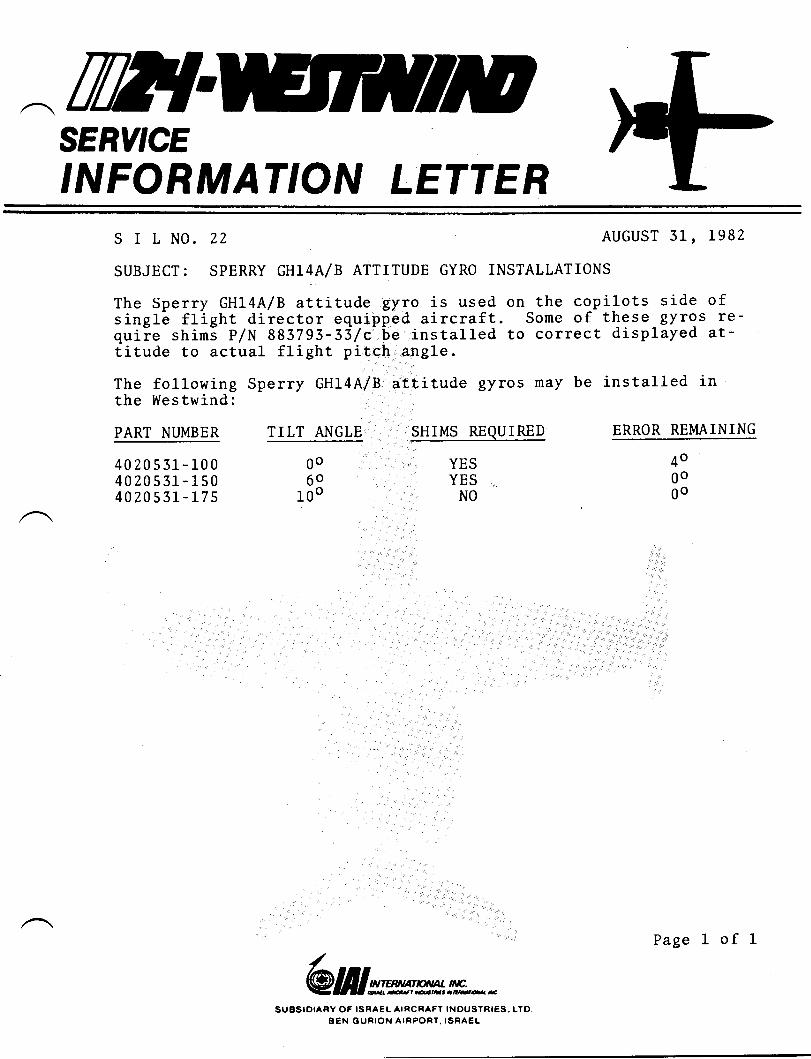
ilI{SERY'CE,NFORMAT'ON LETTER
s I L NO. ZZ AUGUST 31, 1982
SUBJECT: SPERRY GHl4A/B ATTITUDE GYRO INSTALLATIONS
The Sperry GHl4A/B attitude gyro is used on the co-pilots side ofsingle flight director equipped aircraft. Some of these gyrgs re-quiie shiml P/N 883793-33/c-be installed to correct displayed at-ditude to actual flight pitch angle.
The following Sperry GH14A/B attitude gyros nay be installed inthe Westwind:
PART NUMBER TIIT ANGLE ERROR REMAINING
4020531-1004020551-1504020531-175
0o6o
100
SHIMS REQUIRED
YESYES .:)
NO
4o0ogo
/@Wwrmffi**
SUESIDIARY OF ISRAEL AIRCRAFT INDUSTRI€S.. LTO,BEN GURION AIRPORT. ISRAEL
Page 1 of I
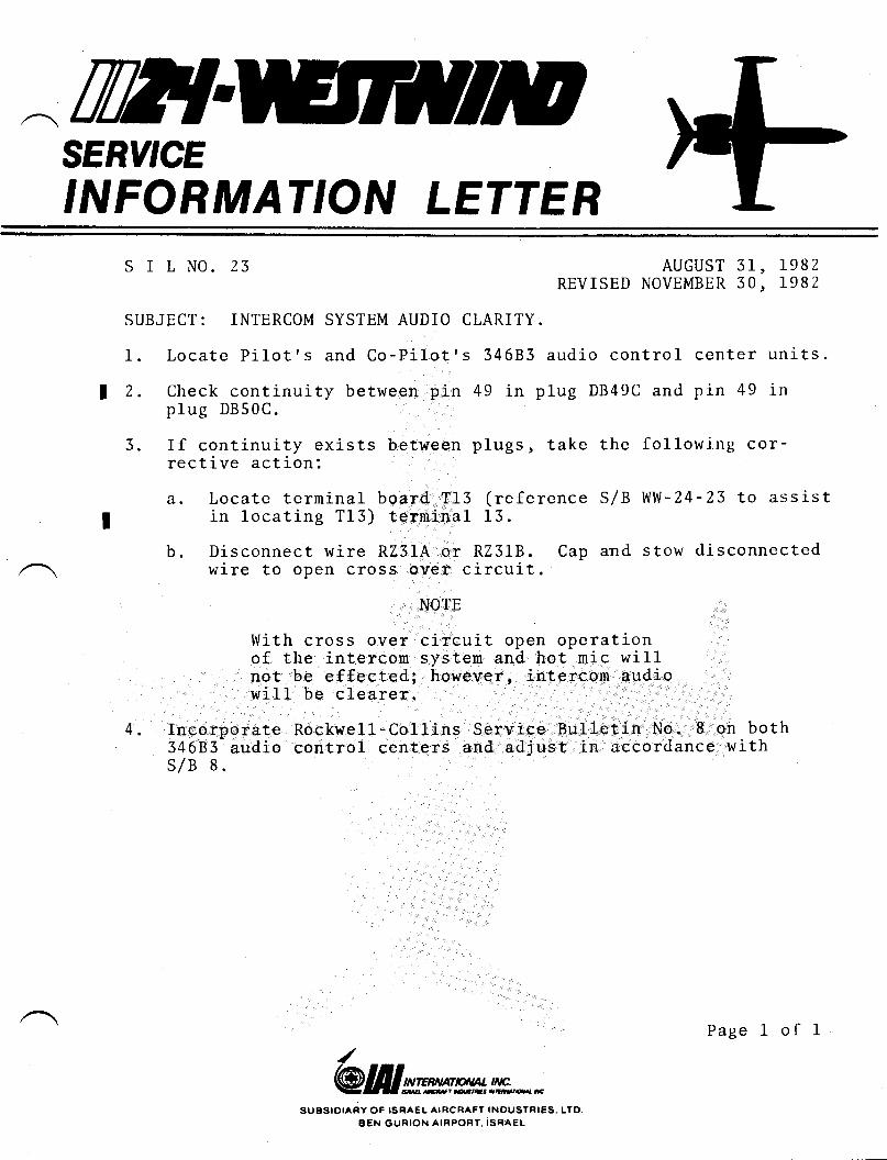
^TTTISERY'CE,NFORMAT'ON LETTER
S I L NO. 23 AUGUST 31, 1982REVISED NoVEMBER 30, 1982
SUBJECT: INTERCOM SYSTEM AUDIO CLARITY.
1. Locate Pilot's and Co-Filot's 34683 audio control center units.
a 2. Check continuity between pin 49 in plug DB49C and pin 49 inplug DB50C.
3. If continuity exists between plugs, take the followirtg cor-rective action:
a. Locate terminal board T13 (reference S/B WW-24-23 to assistI in locating T13) terminal 13.
b. Disconnect wire RZ31A or RZ31B. Cap and stow disconnectedwire to open cross oYer circuit.
4.
NOTE
With cross over circuit open operationof the intercom system and hot mic willnot be effected; however, intercom audiowill be clearer.
Incorporate Rockwell-Collins Service Bulletin No. 8 on both34683- audio control centers and adjust in accordance withS/B 8.
/@lfllwrm!!h**
SUBSIOIARY OF ISRAEL AIFICRAFT INOUSTRI€S. LTOAEN GURION AIBPORT. ISRAEL
Page I of 1
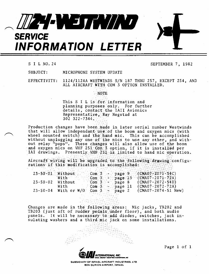
TW{SERY'CE,NFORMAT'ON LETTER
S I L NO. 24
SUBJECT:
EFFECTIVITY:
SEPTEMBER 7, 1982
MICROPHONE SYSTEM UPDATE
LI24/LL24A WESTWTNDS S/N 187 THRU 257 , EXCEPT 254, ANDALL AIRCMFT WITH COM 3 OPTION INSTALLED.
NOTE
This S I L is for information andplanning purposes only. For furtherdetails, contact the IAII Avionics
fft':;;ii?ii:"' RaY Negstad at
Production changes have been nade in later serial number Westwindsthat will allow independant use of the boom and oxygen mics (withwheel nounted switch) and the hand nic. This can be accomplishedwithout unplugging any one of the mics to use any other, and with-out relay "pops". These changes will also al1ow use of the boomand oxygen mics on VHF 25L Com 3 option, if it is installed perIAI drawings. Presently YHF 251 is limited to hand mic operation.
Aircraft wiring will be upgraded to the following drawing configu-rations if this nodification is accomplished:
Changes are madeT8203 (just aftpanels. It willsulating washers
in the followingof rudder pedalsbe necessary toand a third nic
areas: Micunder floor)add diodes,j ack on some
(cMA07 -2071-s4C)(cMA07 -207L.-72A)(cMAo7 -2072-s4D)(CMAO7 -2072-72A)(CMAO7 -207 4-51 New)
j acks , '18202 and, and both audioswitches, jack in-installations.
23-50-01. Without}llith
23-50-02 Withoutwith
23-50-04 With or W/0
Com 3Com 3Com 3Corn 3Con 3
- page 9- page 13- page 8- page 11- page 2
/@lIIwrwmn*
SUBSIDIARY OF ISRA€L AIRCRAFT INDUSTRIES,. LTOBEN GURION AIRPORT, ISRAEL
Page 1 of 1
THSERY'CE,NFORMAT'ON LETTER
s I t N0. z5 SEPTEMBER 7, L982
SUBJECT: AFT BAGGAGE COMPARTMENT MIC WIRING CONFORMITY CHECK.
EFFECTIVITY: 1124/LLz4A WESTWIND, S/N 240 AND SUBS.
1. Gain access to pilotts aud.io control center and terrninal boardT L4. In nost aircraft the units are located at floor levelbehind vanity,
Z. Reference Wiring Manual pages 23-50-05 effective on your air-craft and locate plug DB49e and terminal board T L4.-
3. Accornplish the following chscks with the aid of an ohm meter:
d. Assure that wi:res on terninal board T L4 terninals 10 andL4 are not reversed. Terminal 14 is grounded and shouldhave wire shield glgg1r4? attached. Tenninal 10 shouldhave wire number RZ32&24 attachdd.
b. With ohm meter, assure that wire RZ32A24 connects betweenT 14 terminal 10 and DB49C pin 51. This wire must not goto pin 49 as has been found on sone installations.
c. Make :uTe terninal board T L4 terminal L4 is properlygrounded o
4. Reference Wiring Manual pages 25-50-06 effective your aircraftand ensure that r+ire shield ground for wire R2337824 is con-nected to terminal board T 14 terninal 14 and not terninal 15as shown in Wiring Manual.
5. Check aft baggage mic and phone jacks to assure they are notgrounded at their mounting (these jacks are grounded at theaudio centers). Add lneulating shoulder washers, if required,to insulate mounting pf Jacks.-
Acconrplishment of the 5 Steps listed above will correct weak orinoperative baggage conpartment mic, or squealing in the cockpitintercom system.
Ihe aft baggage compartment comuunication system is operationalfrom pilot's side onLy. Should the cabin call bell ring when theaft headset is plugged in, the bel1 can be silenced by pulling DCcircuit breakers for autopilot annunciator and fl.ightphone.
/@Wwtwm**
SUBSIOIARY OF ISNAEL AIFCBAFT INDUSTNIES.. LTDBEN GURION AIFPORT. ISRA€L
Page 1 of 1.I
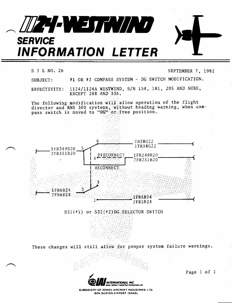
TTHSERY'CE,NFORMAT'ON LETTER
S I L NO. 26
SUBJECT:
EFFECTIVITY:
SEPTEMBER 7, 1982
#1 OR #2 COMPASS SYSTEM - DG SWITCH MODIFICATION.
ILZ4/LLZ4A WESTWIND, S/N 154, 181, 205 AND SUBS,EXCEPT 288 AND 336.
TR38G2 2
I'l'R38(;tZ-
1FB2 49ts20 ,SFBZ.sr82s-l
The following nodification will allow operation of the flightdirector and-RNS 300 systems, without heading warning, when com-pass switch is noved to rfDGtt or free position.
, 7Fts349B202F8351B20
RECONNEC]'
, LFB6B24, 2FB6B24 IFB582 4
2FB5B24
-1
S31(#1) or S32(#2)DG SELECTOR SITII TCH
These changes will still allow for proper system failure warnings.
/@Wwrw!!&**
SUESIOIARY OF ISRAEL AIRCRAFT INOUSTRIES.. LTDBEN GURION AIRPORT, ISRAEL
Page I of I
ttE{SERY'CE
'NFORMAT'ON LETTER
S I L No . 27 November j0, lggzSUBJECT: UPPER AND LOWER NLG BEARING PRECAUTIONS
It has come to the attention of IAII that pressure washing proce-dures used in the area of the nose landing- gear may be coitiibutingto failures of the upper and lower strut Eeirings.'It is recommended that special precautions be taken to prevent waterfrom being forced thru tlre strut seal areas during wash- down of thenose gear. These areas should be covered while uiing pressure wash-ers and the area hand cleaned and thoroughly dried uft^"r cleaning.
Co-mp-liance with Service Letter No. WW-2491 will improve the sealingof the strut and reduce the possibility of moistur-e getting to thesebearings. Also the inspection and lubrication recomlnended-by thisservice letter will further protect the bearings from damage andfailure should any moisture -get by the strut seals.
/@lfilwtw!!&**
SUESIDIARY OF ISBA€L AIRCRAFT INOUSTRIES, LTD.BEN GURION AIRPORT. ISRA€L
Page 1 of 1
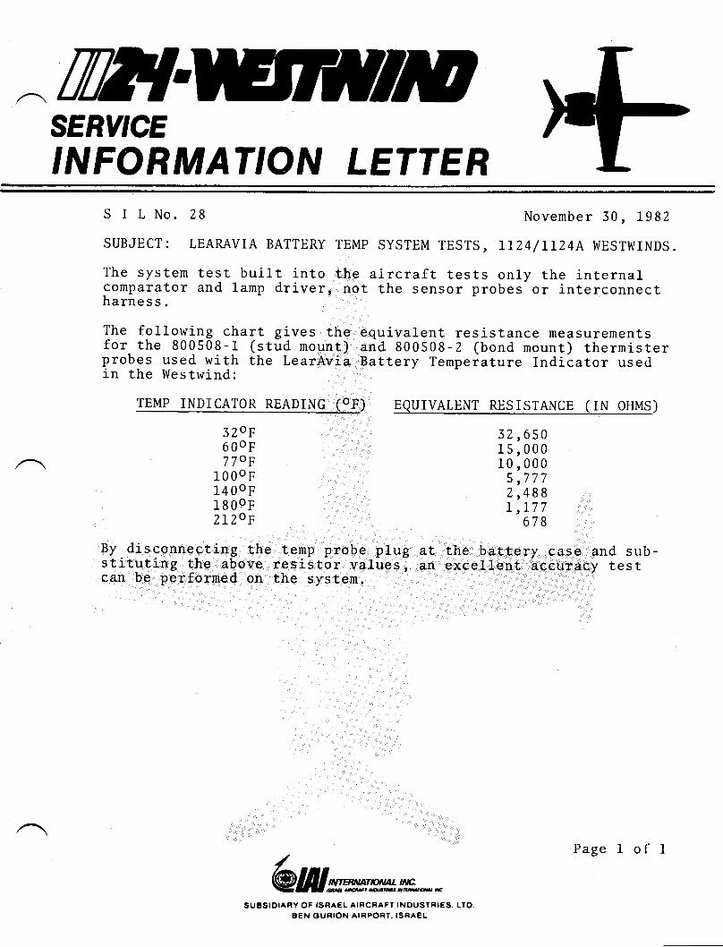
SERY'CE,NFORMAT'ON LETTER
S I L No. 28 November 30, 1982
equivalent resistance measurementsand 800508-2 (bond mount) thermisterBattery Temperature Indicator used
SUBJECT: LEAMVIA BATTERY TEMP SYSTEM TESTS , LT24/LLZ4A WESTWINDS.
The system test built into the aircraft tests only the internalcomparator and lamp driver, not the sensor probes'or interconnectharness.
The following chart gives thefor the 800508-1 (stud mount)probes used with the LearAviain the Westwind:
TEMP INDICATOR READING (OF) EQUIVALENT RESISTANCE (IN OHMS)
3?,oF6 00F7 70F
1000F14 00F1800F?,L?cJF
32,65015,00010,000
5,7772,488L,177
678
By disconnecting the temp probe plug at the battery case and sub-stitgting the above resistor values, otr excellent accuracy testcan be performed on the system
@lIIrcwwmn*SUESIDIARY OF ISRAEL AIRCRAFT INOUSTRIES
8EN OURION AIRPONT. ISRAELLTO
Page 1 of I
TilT{SERY'CE,NFORMAT'ON LETTER
There are ten (10) screws in the lower wing root access plate oneach wing. Removal of this plate was required to accomplish Ser-vice Letter No. WW-2466 and is required during routine inspectionof the aircraft.All screws should be removed frorn these access plates and theaileron push-pul1 tube checked for scratches that could have beencaused by the one long screw, required in each p1ate, being in-stalled in the wrong location. If scratches are found in push-pull tube they must be polished out before reinstalling accessplates.
Reinstall access plates with 9 each MS24694548 screws and 1 eachMS24694S49 screw (longer screw nust go thru spar cap angle). Itis recommended that the longer MS24694S49 screw heads and theirLocation on the access plates be color coded before reinstallation.
S I L No. 29 NOVEMBER 30, 1982
SUBJECT: WING ROOT LOWER ACCESS PANEL ATTACHMENT CHECK.
/@lIIwrm!!&n*
SUESIOIARY OF ISRA€L AIRCRAFT INOUSTRIES.. LTDBEN GURION AIRPORT. ISRAEL
Page 1 of 1
SERY'CE,NFORMAT'ON LETTER
S I L NO. 30
SUBJECT: USE OF BIOBOR JF FUEL ADDITIVE
February 28, 1983
978 on the
of Biobor
Attached is a copy of U.S. Borax Service Bulletin No.use of Biobor JF fuel fungicide for your infornation.Refer to Chapter LZ of the Maintenance Manua1 for useJF in LL24/LL24A Westwinds,
@frlwwmn*SUSSIOIAFY OF ISRAEL AIFCRAFT INOUSTNIES. LTO
BEN GURION AIRPORT. ISRAEL
/
Page I of I
rWTSERY'CE,NFORMAT'ON LETTER
SIL No. 314 JULY 15, 1983
This Service Infornation Letter supercedes SIL No. 31, datedMarch L, 1983, in its entirety.
SUBJECT: REPLACEMENT OF BMKE ASSEMBLY TO AXLE MOUNTING BOLTS.
A new replacement bolt has been approved for brake assernbly toaxle mounting. The new bolts P/N NAS 6705-U8 should be installedas soon as practical but not to exceed the accumulation of 400landings on existing bolts or brake overhaul, which ever occursfirs t .
The new bolts are manufactured from corrosion resisting steeland will replace all earlier cadmium plated bolts. Cadmium platedbolts should no longer be used for this installation.See Service Letter No. WW-24103 for further details.
/@Wwrwmn*
SUBSIDTAFY OF ISBAEL AIFCRAFT INOUSTRI€S. LTDBEN GUNION AIRPORT, ISRAEL
Page 1 of 1
:TWTSERY'CE,NFORMATION LETTER
S I L No.
SUBJECT:
32 I\,IARCH 31, 1983
Attached you will find a copy of Garrett AiResearch serviceBulletin No. 5-2297 dated Jan 15/81. This Garrett servicebulletin provides the instructions for installation of GarrettModification Kit No. 830164-2. This kit witt allow a p/N572375-2 turbine to replace a P/N 52375-5.
REPLACEMENT OF P/N 572375-3 COOLING TURBINE WITH P/N57 237 5-2 COOLING TURBINE.
For updating of refrigeration units with p/N s7?,375-r seriesturbines refer to Service Letter No. WW-2442.
/@frlrcwmm**
SUESIOIARY OF ISRAEL AIRCRAFT INOUSTRIES., LTOBEN GURION AIRPORT. TSRAEL
Page I of I
AIRESEARCH MANUFACTURIilG COMPA'{YOF CATIFORNIA
SERVICE BULLETINMode1 l-12\
REFRIGEMTION UNIT - Converslon of 22OOL654 Refrlgeratlon Unlt (fteta Retrofit) to2OOL65-2 Refrlgeratlon Unlt (Productlon) by replacing cooling'turbl,ne
SECTION T
PLAI{NING INFORMATION
A. Effectivity
This service bulletin is applicable to the folloving refrigeration units:
Part No. Aircrafb Appllcatlon
Model ll2lraOOL55-3 Series L
' B. Reason
(f) Problen: Requirenent to install Part No. 572375-2 production CoolingTurbine in place of Part No. 5723"15-3 Cooling Turbine has occurred inthe field.
(Z) Baglglgglqj Part No. 5723]r-2 productlon Cooling Turblne is usable inPart No-200165-3 Refrigeration unit vith addition of an adapter.
(3) Actlon: Replace Part No. ,'12375-3 Coollng Turbine wlth Part No. 572375-2CooJ-ing Turblne per thlsi servtce bulletln.
C. Descriptlon
Replace ,72375-3 Coollng turblne vith 572375-2 CooLing Turbine and add adapterassenb\r and cover plate to provlde for connection to heat exchanger ram airinlet duct.
D. Approval
Not applicable.
E. Manpower
_^. Approxinately 2.0 nan-hours are required for replacing cooling turbine, using/ \ 8lof5\-f Refrlgeratlon Unit Modification Kit.
BnlLetin No. 5-2297Page 3- of !
Serial l{o.
AII
Jan 15/81
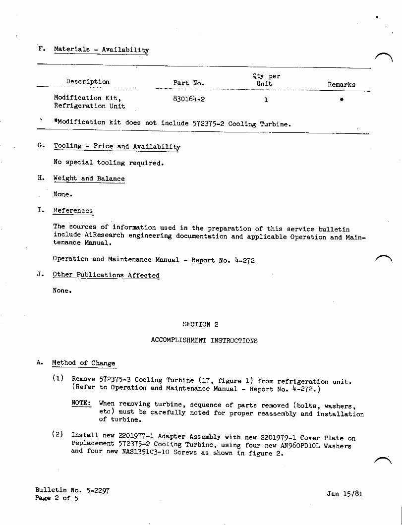
F. Materials - Availability
Description Part No.Qty perUnit Remarks
Modlflcation Klt, g3otd\_2 IRefrigeratlon Unlt
' tModification kit does not lnclude 572375_2 Cooling Turbine.
G.
No special tooling required.
H. Weight and Balance
None.
I. References
The sources of i.nfornatlon used in the preparation of this service bulletininclude AiResearch engineering doeumentatton and applicable 0peration and Main-tenance Manual.
Operation and Maintenance Manual - Report No. l+-2?2
J. Other Publicatipns Affected
None.
SECTION 2
ACCOMPLISHI\MNT INSTRUCTI0NS
A. Method of Changq
(r) Renove 572!15-3 cooling Turbine (t?, rigrrre l) from refrigeration unit.(Rerer to 0peration and Maintenance Manual - Report uo. 4]aTi.i- -.'---
NoTE: l{hen removing turbine, sequence of parts removed. (uorts, washers,etc) nust be careftrlly noted ror prlper reassembly and installationof turbine.
Q) Install ne$ 22019?T-t Adapter Assembly with nev 2201!?9-t Cover plate onreplacemenr 572375-2 Cooling Turbine, uslng four new nwg6opnrol washersand four nev NASl351c3_10 Screvs as shown ln figure 2.
Bulletln lfo. 5-22nPage 2 of I Jan 15/81
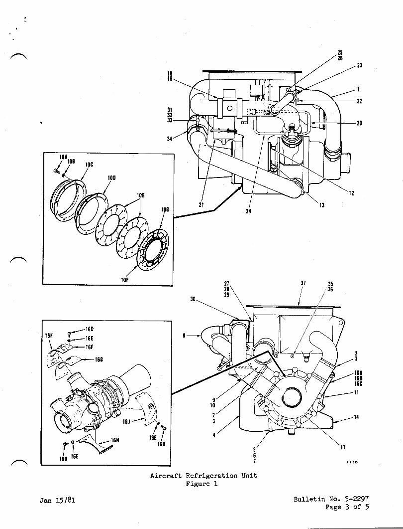
3l3233
34
Ir0
2
3
4
23
r6tt68r6c
il
l4
Aircraft Refrigeration UnitFigure I
No. 5-229'lPage 3 of 5
.ran 15 /81 Bulletin
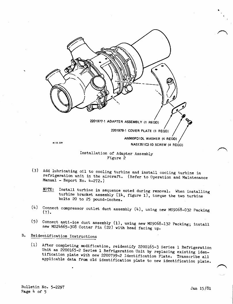
^ -r0. 129
(:)
(h)
Installation of Adapter AssemblyFigure 2
Add lubricating oil to cooling turbine and install cooling turbine inrefrigerat'ion unit in the aircraft. (Refer to operation and MaintenanceManual - Rieport No. \-272. )
NOTE: Install turbine in sequence. noted. during removal. when installingturbine bracket assenbly (tlt, figure 1)l torque the tvo turbinebolts 20 to 25 pound_Lnches.
connect corrpressor outret d.uct assernbry (b), using nev MS9o5g-032 packing(T).
(l) Connect anti-lce duct assenbly (I). usincnev u,S2l+55F-:Og Corter pin (e-Z ) viin neaE
Reidentiflcation Instructions
(f) lfber conpfeting nodification, reidentify 22OOf65_3 Series I RefrigerationUnit as 22A0]'65-2 Series 1 Refrigeration Unit by replacing existing iden-tification plate vith new 22OO79g-2 Identification plate. Transcribe allapplicable data from o1d identification plate to nev identification plate.
2201977-1 ADAPTER ASSEMBLY (1 READ}
2201979.1 COVER PLATE (T REODI
AN96OPD1OL WASHER (4 REODI
NASr3slC3.t0 SCREW (4 REODI
new t,tS9058-132 packing; installfacing up.
rl
Bulletln No. 5-2297Page l+ of !
Jan 15/81

SECTION 3
MATERIAL INFORMATION
The folloving refrigeration unit nodlfication kit ts required for each refrigera-tion unit to be nodified and may be obtained from Atlantic Aviation Corporation.
' New OId Instructions-Part No. aW Key Words Part No. Disposition
572375-2 1 Cooling Turbine jTZ37j-38:or5\-e 1 Modification Kit,
Refrigeration UnitConsisting of:
22O977-L 1 .AdapterAssembly22O979-L L .CoverPlate22OOT99-2 1 . Iclentification Ptate n0O799-3 BNA^S1351C3-10 l+ . ScrerrAI{950PD10L \ . WasherMS9058-032 I . Packing!,!59058-132 I . Packing!tS2\655-308 I .Cotterpin
MS9o58-032 Bnsg058-132 B
!rs2l+555-308 B
Disposition Code A: Replace as specified in service bulletin..A'/ \ Dispositlon Code B: Scrao.
Bulletin No. 5-2297Page 5 of 5
Ja.n 15 /81
Til?{SERY'CE
'NFORMAT'ON LETTER
SILNo.33
SUBJECT: ENGINE CROSS START
MARCII 31, 1983
Engine cross start is a normal procedure outlined in the AFM,titled I'Starting Engines Using Battery Power".
Engine cross start may be d.efined as the procedure wherein the op-erating generator of the first engine started is operating in par-allel with the aircraft batteries, thereby providing generatorassist to the batteries for starting the setond englne.
Step 16 of Nornal Procedures reacls "DC ammeter, op€rating engineBELOW 100 AMPS (27.5V mininurn).
Occasionally, the requirements of Step 16 may cause significantdelay in initiating second engine start.The operator may expedite second engine start by turning the op-erating generator switch OFF, then back ON. This will cause thegenerator to enter the 1.5 volt reduction mode and reduces gener-ator output to less than 100 AMPS, during second engine start.
NOTE
The procedure described for ex-pediting start of the secondengine may result in excessivedischarge of batteries and thusshorten battery life.
@frlwwmn*SUASIDIAFY OF ISRAEL AIFCNAFT INDUS'RIES.. LTO
B€N GURION AIRPORI. ISRAEL
Page I of 1
TWTSERY'CE,NFORMAT'ON LETTER
Some aircraft are experiencing intermittent problems with thefemale "fork" contacts and coax connectors in the Collins "ThinLine" connectors used on the VIR 30, ADF 60, FCS 80, APS 80, etc.
These problems are generally observed while trouble shooting asystem defect, and simply removing and reinstalling a suspect"black box" cures the problen.
For corrective measures, Collins has a kit available, containinga new connector, mounting adapter, and hardware for most "Pro Line"equipment.
Refer to Collins Pro Line Equipment Service Information Letter1-82, dated 2L Jul 82 for kit part numbers. Pins are to be order-ed separately.
This Collins SIL gives complete instructions, inclucling spccialtooling required.
S I L NO. 34 APRIL 15, 1983
SUBJI]CT: INTERMITTENT COLLINS RACK MOUNT CONNECTORS.
@lfllwmn*SUESIDIAFIY OF ISRAEL AIRCRAFT INOUSTRIES.. LTO.
8EN OURION AIFPORT. ISRAEL
/ Page 1 of 1
f
SERVICE PUBLICATIONS
revision noticesrL No. 35
SUBJECT: VIBRATION LEVEL FOR #2 ALTIHETER
lf ay 22, 1987
CANCELLATION NOTICE
This servlce rnformatj.on Letter is hereby cancelled. Arlinf ormation contalned herein has been lncorporated in SerfieBurretln No. LLz4_s4_ozL. _- U*J)t/o* \
Tom Vail, ManagerTechnical Services
/@Wwmn
3ulsrol^nY of rstA€t alRcFAFl lNousTelEg. LlogEN OURION AIRPOET. ISRAEL
Page 1 of 1

SERY'CE,NFORMAT'ON LETTER
S I L No. 35
SUBJECT: VIBRATION LEVEL FOR #2 ALTIMETER.
May 16, 1983
A smal1 vibrator is built into the #2 altimeter to prevent needlesticking. 0n some aircraft a variable potentiometer (P1) is usedto control voltage to the vibrator and thereby the level of vibra-tion. There are other aircraft that have the vibrator circuitdirect wired to receive a fuLl 28V.
If your aircraft's #2 altineter has developed sticking problemsaccomplish a voltage check by disconnecting the connector on theback of the altimeter and testing per Figure 1.
If voltage reads below 20V, locate printed circuit board P/N5835513-9 (below copilot HSI) and adjust potentiometer (P1) to16-l8V or jumper potentioneter (Pf) per Figure 2.
NOTE
Noise leve1 of vibrator will increaseas volcage rs lncreaseo.
/@Wwrmmn*
SUBSIOIARY OF ISRA€L AIRCRAFT INDUSTRIES,, L'OBEN GURION AIRPORT. ISRAEL
Page I of 2
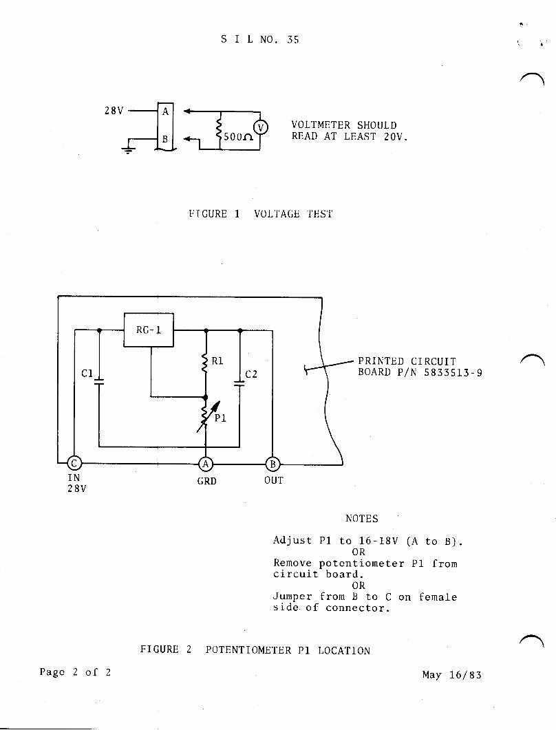
SIt N0. 35
IJ I GURE 1 VOJ,l'AGE 'TES'T
VOLTMETER SHOULDREAD AT LEAST TOV.
PRINTED CIRCUITBOARD P/N 5833s13-9
GRD OUT
NOTES
Adjust p1 to 16-18V (A to B).OR
Remove potentiometer P1 fromcircuit board.
ORJumper from B to C on femaleside of connector.
Page 2 of 2
FIGURE 2 POTENTIOMETER P1 LOCATION
May 76 / 83
:twtSERY'CE,NFORMAT'ON LETTER
SILNo..56 May 16, 1983
SUBJECT: 1124 WESTWIND REFRIGEMTION UNIT INSTALLATION.
Attached is AiResearch Report No. 4-272 on the refrigeration unitused in LL24 Westwinds. This report covers operation and mainte-nance, including replacement of cooling turbine. Be sure and fol-low the procedures called out in Report 4-272, especially torquevalues for screws and bolts.
To further assure proper installation of refrigeration unit cautionshould be exercised in assenbly of the Peri-Seal Coupling P/N 54A27(located in the duct from the conpressor outlet of the turbine tothe secondary heat exchanger). New seals P/N 460-200 should be in-stalled wherever Peri-Seal Coupling is disassembled or leakage issuspected. Reassenble Peri-Seal Coupling per Figure 1.
/@Wrcwwm**
SUSSIOIAFY OF ISRAEL AIRCRAFT INOUSTRIES,, LTOBEN OURION AINPORT, ISRAEL
Page I of 2
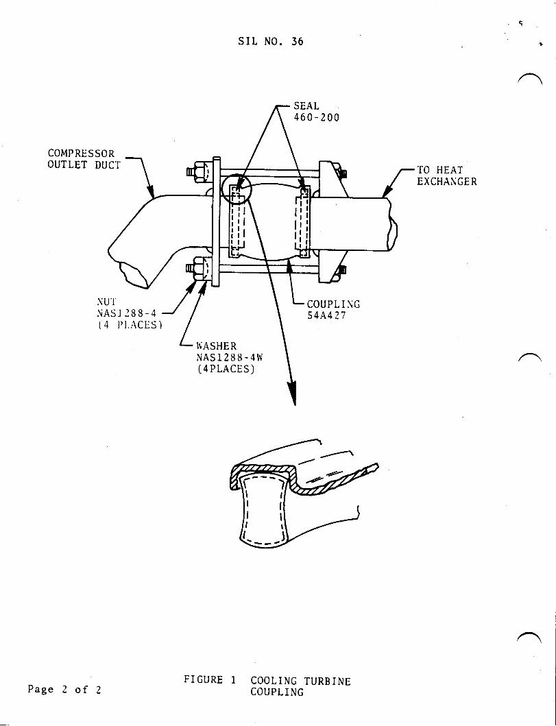
slt No. 36
SEAL460-200
COMPRESSOROUTLET DUCI' TO HEAT
EXCHANGER
NU'INAS-l 188-4( 4 l'l.r\CtjS )
COUPL I \-G544427
IiASHERNAS1288-4W(4PLACES)
COOLING TURBINECOUPL I NGPage 2 of 2
FIGURE 1
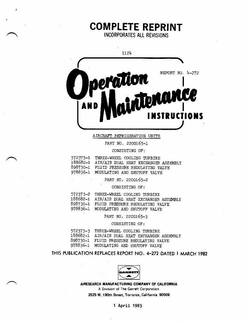
REPORT N0. \-272
I
572375-rr8858e-r898730-1978835-1
57237r-2rBB58e-r89Bzso-r978836-1
572375-3rB858e-rBg8t:o-r9788:5-r
THIS PUBLICATION
AIRESEARCH If,ANUFACTURING COTIPANY OF CALIFORI{IA
A Division of The Garrett Corporation
2525 W. l90th Street, Torrance, California 90509
COMPLETE REPRINTINCORPORATES ALL REVISIONS
r12!
AIRCNAflT REF'RIGMAT]ON UNITS
PART NO. 2200r65-iCONSISTING OF:
TIIREE-}J}IEEL COOLING TLTRBINEATN/RTN DUAL HEAT D(CHANGM ASSN,IBLYFLUID PRESSI.IRE REGUI,ATING VALVEMODULATING AI\ID SHUTOI'F VALVE
PART No. zzoot5j-zCONSISTTNG OF:
TI{REE-I'I}IEEL COOLING TURBINEAIR/AIR DUAL HEAT EXCHANGER ASSUVIBLYFLUTD PRESSIJRE REGUI,ATING VALVEMODUI,ATING AND SHUTOFF VALVE
PART NO. 2200:-65-3
CONSISTTNG OF:
THREE-}IHEEL COOLING TURBINEAIR/AIR DUAL HEAT EXCHANGER ASSE}4BLYFLUID PRESSURE REGUi,ATING VALVEMODUI,A,TING AMD SHUTOFF VALVE
REPLACES REPORT NO. 4-272 DATED I MARCH 1982
TSIRUCIIOXS
1 April 19E3
usT 0r ffr$flYt Pr8ts Thc ponion of tb rcrr dfecrcd br rh. |lrcr rcvirion rr indrcerdbt . r.nac.l lioc ia rbc ourer orrjiar of rhr Ftr,
TOTAL NUI.tsER OF PAGES IN
PageNo.
Tltle .. ......... .... AprBlank . ... .. .. ... . .. . AprA ..........o........ AprB Blank . ........ .. .. Apr1 thru 4 ... ..... .... Apr4.1 r....o...o....... Apr4.2 Blank ........... Apr5 thru 10..o........ Apr
THIS PUBLICATION IS 16, CONSISTING OF THE FOLLOI{ING:
1/83't/83't/831/831 /831/831 /831/83
. Thc rrtcri* indicrtct prjcr rcvird, rddcd, or dclcrcd by rhc <urcnr rcvirim.
Report No. 4-272
il$lr un'l l|vttto tAott. o$rroY tu'|l$Dto ?Aot3.
A/B
Report No. l+-272
SECTION I
INTRODUCTION
I-1. IDENTIFICATION.
L-2. This publicatlon provides operation and maintenance instructions for AircraftRefrigeration Units Part No. 2200165-1, 2200I:61-2 and 22OOl6|,4, nanufactured byAiResearch Manufacturing Corpany, Division of The Garrett Corporation, Torrance-,California.
1-\. This refrigeration unit is used to reduce the ternperature of engine bleedair for use in an aircraft air conditioning system.
TABLE I. LEADING PARTICULARS
Cooling Turbine Part No.,7Z3T1-L,,72375-2, and, 572375_3:TJrye t " t " ' a.. o.. a o.. a....... a........... r..... a... a a... a a...... a o...... 3 wheelLubricant . . . . . . . . . . . . o . . . o . . . . . . . . . . . . . . . . . . . . . . . . . . . . . . . . . . . . . . . . . . MIL-L-23619Anpunt of Lubricant ...... o.... o.......................... o...... 120 cc (approx)Weight .o.o.................................................... lh.OO fU (aiirox)
Ileat Exchanger Assembly part t'lo. tB86B2-t:' TWe "". '. o...a....... a.... ao oio o. o. a.... o... a..a......... a.........o. Air/Rir
Weight t '................ o.............................................. f6.3i fURegulating Valve part No. 89BTgO-f:
T;pe ....... o..... o................ o................ Spring loaded norrrally openRegulated Prgssure .. ................................... o.......... 2[ to e6 psigWeight " " '......................................... o............. .. 2.10 Ib max
Modulating Valve part No. 978836-L:Ty?e '............................... o......... o.. Spring loaded normally closgdOperating Current .... o................... o.................. 0 to 105 rnilliampsWeight "........... o... o............... o... r...................... .. 2.35 Ib naxTotal Weight .................................................... \O.OO tU iapprox)
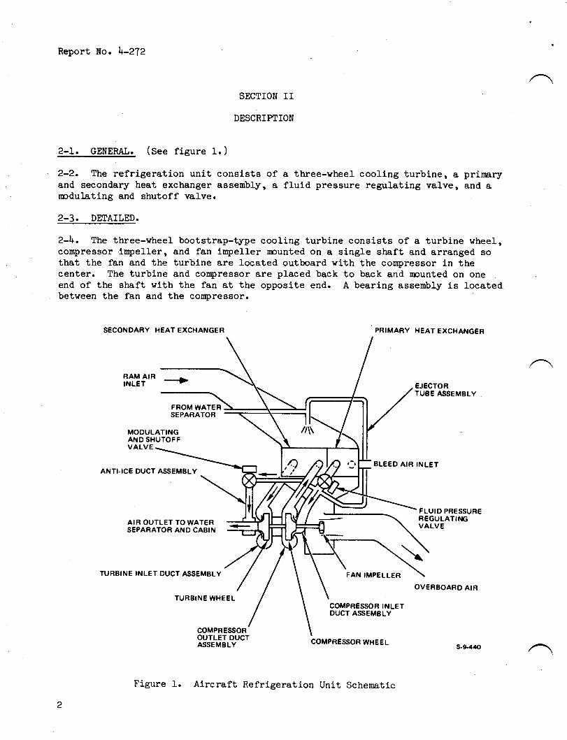
Report No. \-2?2
SECTION II
DESCRIHIION
2-L. GENEML. (See figure 1. )
2-2. The refrigeration unit consists ofand secondary heat exchanger assembly, arcdulating and shutoff valve.
a three-wheel cooling turbine, a' prinaryfluid pressure regulating valve, and a
2-3. DETAILED.
2-\. The three-wheel bootstrap-type cooling turbine consists of a turbine wheel,compressor.inrpeller, and fan inrpeller rcunted on a single shaft and arranged sothat the fan and the turbine are located outboard with the compressor in thecenter. The turbine and conpressor are placed back to back and nounted on oneend of the shaft with the fan at the opposite end. A bearing assembly is Iocatedbetween the fan and the coupressor.
SECONDARY I{EAT EXCHANGER PRIMARY HEAT EXCHANGER
RAM AIRINLET --+ EJECTOR
TUBE ASSEMBLY
FROM WATERSEPARATOR
MODULATINGAND SHUTOFFVALVE
BLEED AIR INLETANTI-ICE DUCT ASSEMBLY
AIR OUTLETSEPARATOR
TO WATERANO CABIN
FAN IMPELLER
COMPRESSOR INLETDUCT ASS€MBLY
FLUID PRESSUREREGULATINGVALVE
OVEREOARD AIR
TURBINE INLET DUCT ASSEMBLY
TUREINE WHEEL
COMPRESSOROUTLET OUCTASSEMBLY COMPRESSOR WHEEL
Figure 1. Aircraft Refrigeration Unit Schernatic
s.$440
Report No. h-272
2-5. The primary and secondar"Xr heat exchangers are air-to-air typee conslsting ofa core assenbly containlng a serles of plate tubes vith integral tube finsseparated by cooling air fins. The core assenrbly is enclosed vlthln welded andbrazed Ilan assemblies vith integral fan and discharge ducts for directtng hot lnletair and coolirqg alr through the refri6eratlon unlt. The heat exehaner is oplit sotlnt approximrrtcly one thlrd of the unlt functlons ae the prlmary heat exchangerand two thirds as the secondary heat exch&lg€r. The unlt ls of alumtnum plate flnconstruction vith each section a slngle pass crossflov configuration. Cooling a1rflovs in parallel through the cold slde passages of the cor€r
2-6. The fluid pressure regulating valve is a 2-inch line slze, pneurnaticallyactuated, spring loaded open butterfly-type valve vhich functions to control corppressor inl-et pressure to 25 psig.
2-7. The modulation and shutoff valve is a normally closed, l-inch electro-pneumatically actuated right angle poppet-type valve. The valve controls therefrigeration unit cold air outlet to a niniraum value of 35 degrees F (nominal)by rnodulating the flov of compressor inlet air to the anti-ice muff at the turbinedischarge. The valve position is controlled by a torque motor which varies thevalve actuator pressure in response to electrical signals from a 35 degree Ftenp,erature control/sensor located outside the refrigeration unit.
SECTION III
OPERATION
3-1. Regulated hot bleed air entering the refrigeration unit passes first throughthe primary section of the heat exchanger where the air is partially cool-ed; thenthrough the pressure regulator valve which conlroIs bleed air pressure to a nominalvalue of 25 psig. The air then enters the compressor component of the three-wheelcooling turbine where the air undergoes an increase in pressure and temperatureduring the compression process. Upon leaving the cooling turbine compressor, theair flows through the secondary section of the heat exchanger wlrere the air iscooled to nearly the tenperature of anrbient cooling air. B1eed air is then exlnndedthrough the turbine component of the three-wheel cooling turbine. This expansionprocess not only reduces the bleed air temperature well below that of the ambientair but produces shafL power to drive the compressor and fan. If the bleed air iscooled belov the dewpoint during the extrnnsion process in the turbine, water vaporin the air vill condense out as snall droplets (fog)r or, if the temperature isbelow 32 degrees l', ice crystals form in the airstream. The cold turbine dischargeair fron the refrigeration unit is passed through a water separator (not part ofthe refrigeration unit) for moisture removal. Protection against ice formation inthe water separator and downstream ducting during all modes of operation is achievedby the action of a temperature control/sensor (not part of the refrigeration unit)and a tenperature/control valve to limit refrigeration unit discharge air to aminimurn of 35 "r' ( 1. 57 "C ) .
3-2. The latent heat of condensed water collected in the vater separator is uti-lized to increase the heatsink capability of the heat exchanger cooling air. Ther"rater inJector nozzle assenbly, vhich is lnrt of the cooling turbine, uses a sna1lquantity of bleed air fron the heat exchanger outlet pan to eJect and atornize thiswater and spray the vater into the face of the secondary heat exchanger section ofthe heat exchangerair by evaporatlon.
core, thereby enhancing the heatslrrk capacity of the coollng3
Report llo. 4-272
3-3. About ?0 percent of the power produced by the turblne ls absorbed by bheeonpreasor and the renalnder ls absorbed by fhc fan, the firnctlon of whlch lc toprovlde anblent coollng a1r for the heai exohangcr durlng ground opcratlon.
SECTION IV
SPECIAL SERVICE TOOLS
4-1. No speelal servlce tools are requlred.
sEcTIOil V
PENIODIC INSPECTION
Note
The following lnspection periods are reconnendatlonsonly. If requlred, in order to be conpatlble wlththe nearest scheduled tnspectlon periods, deviatlonsnof to exceed 10 percent of the reconnended lnspect-tlon perlods are oonsldered practlcal. Servlceexperlence wlll dlctate aetual lnspectlon penlodsto be used.
5-1. 15O.HOUR INSPECTION.
3. Renove plug fron oll draln port and allon o11 to completely draln froncoollng turblne' Install plug ln olt draln port. Renove plug fron o1l fllt port.FllI coollng turblne wlth otl (Speclficatlon MIL-L-23699) bo [op of ftlt port.Install plug ln oil flll port.
I 5-re. (Dereted)
| 5-e. oN-corotTroN tHspgcttot{.
. ?: It ls reconnended that the coollng turblne be renoved fron the refrlgeratlonI unlt and returyned to an approprlabe factllty for repalr/overhaul only lf difeot,lve.
Report No. 4-272
SECTION VI
MAINTENANCE
6-1. CENERAL.
a. l{alntenance of the refrlgeratlon unlt ls llntted !o replacenent of conponentsfound defectlve ln troubleshootlng and the lnspectlon outllned ln Sectlon V. Referto Table II for troubleshootlng lnfornatlon.
4.1 /4.2
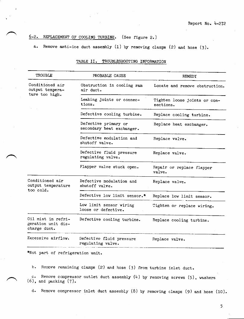
Report No. l+-272
6-2. 4EE1egSUEr1T oF cooLrNG TURBTNE. (see figure 2. )
a. Remove anti-ice duct assenbly (1) by removing cramln (2) ana hose (3).
TABLE II. TROUBLESHOOTING INFORI'{ATION
TROUBLE PROBABI,E CAUSE REMEDY
Conditioned airoutput ternpera-ture too high.
obstruction in cooling ram Locate and remove obstruction.air duct.
Leaking Joints or connec- Tighten loose Joints or con-tions. nections.
Defective cooling turbine. Replace cooling turbine.
Defective primary or Replace heat exch&rgerosecondary heat exchanger.
Defective modulation and Replace valve.shutoff valve.
Defective fl-uid pressure Replace valve.regulating valve.
Flapper valve stuck open. Repair or replace flappervalve.
conditioned air Defective moduration and Replace valve.output temperature shutoff valve.too col-d.
Defective Low limit sensor.* Replace lov limit sensoro
Low limit sensor viring Tighten or replace wiring..l-oose or defective.
Oil rnist in refri- Defective cooling turbine. Replace cooling turbine.geration unit dis-charge duct.
Excessive airflow. Defective fruid pressure Reprace valve.regulatlng valve.
*Not part of refrigeration unj.t.
b. Rernove rernaining clamps (2) ana hose (3) frorn turbine inlet duct.
,.\,. Remove conpressor outlet duct assembly (l+) by rernoving screws (5), washers/ \ (6), and packing (7).
d. Remove conpressor inlet duct assembly (B) by renoving clamps (g) and hose (fO).
€o Renove screvs (roa), washers^(ron),-rllnu" (roc),_dampener (roo), flappers(ron), and retainer halves (tor, lry). ir n"!pur" (roei-;;";;"", wrinkled, orshov evidence of deterioration, replace ffappeii.f' Remove bracket assembry (r\), bolts (r5), washers (r51, and attaching parts.
tr!, ,liitve cooring turbine (t?) rror plenurn assenbry (u) uy removing borts
h. 0n Aircraft Refrigeration Unit part No. 22OO1Gr_Z, remove screws (f5e), coverplate (r5e), and adapter assenblj-iiAil-ir.i'"lling turbine (r7et. on AircrafrRefrigeration unit part No. 220015>4, "uro.,"-JJ."*J
(16oi,-*";;;." (r5r), covers(16r') ' gasket (r6c) ' cover ."""turv iiaiil-."a Laapter assenbry (rg"r) frorn cooringturbine (r7s).
i' on Aircraft Refrigeration unit Part No. 220or6r-2, instarl adapter assembly(f6c)' cover plate (fesi, "na-"""."r-ii3ef-."_""nf"cement cooling turbine (r7a).On Aircrafl Refrigeration Unit part l,lo. 22001554, install.adapter assembly (f5,f ),cover assembry (r5n), gasket (r5c)'.covers frgi'1, vashers (r5s), and screws (15D)on replacement cooling turbine (rts). Torque
""ruro" (roa,'i5;i'to ro pound-inchesmaximum. Safetyvire screvs, using ltts2)ggii(ilO Lockvire.
J. InstaII repfagement cooling turbine (f?) in plenum assembly (ff; "1an bolts
lift 13I ffiT;"ti:hten uoii".-"irtu' borts are-instalred, crrecr-that cooling tur-
k' rnstall bracket assenbly (rl+) uy instalr-ing bolts (r5), vashers (15), anaattaching parts' The two bol-ls vhich secure the-bracket assemuiy to the cooringturbine nust be torqued to 20 to 25 :-ncrr-pourrJs. check that cooiing turbine doesnot bind after bracket assembly is installed.r' rnstarr retainer harves (tqll loc), frapn9r1.(ror), dampener (too), frange(rOc) and secure with "."r,""" tiOul and screws (1oA).
Report No. l+-2?2
CAUTION
Install flappers (fOe) as shovn in figure 2.rl. Install conpressor inlet duct assernbly (B) by installing clamps (9) and hose(ro).
(di, "*1::il;'ii;:"'"
outlet duct assernbrv (lr) bv lnstalrlns screwa (5), vanhere
o. Connect turbine inlet duct by installing clanps (2) ana hose (3).p' rnstall- anti-ice duct assembly (1) uy instarring cramps (2) ana hose (3).
TING VALVE. (See figure 2. )
,nl'(r.fil""" compressor inlet duct assemblv (8) by removing cranrps (1g) and pack-
b. Remove tube assemUfy (20).
6
Report No. l+-272
c. Install replacement fluid pressure regulating valve (af) Uy installing tubeassernbly (ZO ) , clamps (fB; , and lnckins (19 ).
6-l+. REPLACEMENT OF MODULATING AND SHUTOFF VALVE. (See figure 2. )
a. Remove anti-tce duct assenbly (1) Uy removing prn (22) ana packing (23).
b. Remove tube assenbly (21+).
c. Remove nut on end of tube of compressor inlet duct assenbly (8).
d. Remove bolts (25), washers Q6), and shims (zT, 28, 29).
€r InstaII replaeement modulating and shutoff valve (lO) on heat exchangerassembly (SZ) Uy installing bolts (25), washers (25), and shims (27, ZB, Z9).
f. Install attaching nut on end of tube of compressor inlet d.uct assernbly (8).
C. Install tube assenrbly (21+).
h. Install anti-ice duct assernbly (f) by installing pin (22) ana packing (23).
6-5. nnpr,Rcnunur or Rtn/Rrn HfRt nxcH.a,Nonn Rssnmly. (See figure 2. )
a. Rernove turbine inlet duct connection by renoving clamps (e) ana hose (3).
b. Renove fluid pressure regulating valve (ef) Uy removing ctamps (18) anapacking ( 19 ).
cr Remove nodulating arrd shutoff valve (SO) Uy removing bolts i€r), washers(261, and shims (zT, 28, 29).
d. Remove conpressor outl-et duct assenbly (l+) by rernoving nuts (Sf ), washers(f), studs (::), and coupline (3h).
€o Remove plenum assembly (ff), with cooling turbine (tT) attached, by removingbolts (35) ana vashers (36).
f. InstaII replacement.heat exchanger assernbly (37) on plenum assernbly (ff ) Uyinstall-ing bolts (35) ana washers (:6). Apply adhesive-sealant (uititary Specifi-cation |4IL-A-\5106R) Uetween heat exchanger (3?) ana plenum assembly (ff).
go Install- compressor outlet duct assembly (|+) by installing nute (31), washers(:z ) , studs (:: ) , and coul:line ( 3b ).
h. Install modulating and shutoff valve (:O) tV installing bolts (25), washers(26) , and shirns (27 , 28, 29) .
i. Install fluid pressure regulating valve (Zr) Uy installing clarnps (f8) anapackins (19).
J. Connect turbine inlet duct by installing clamps (2) ana hose (3).
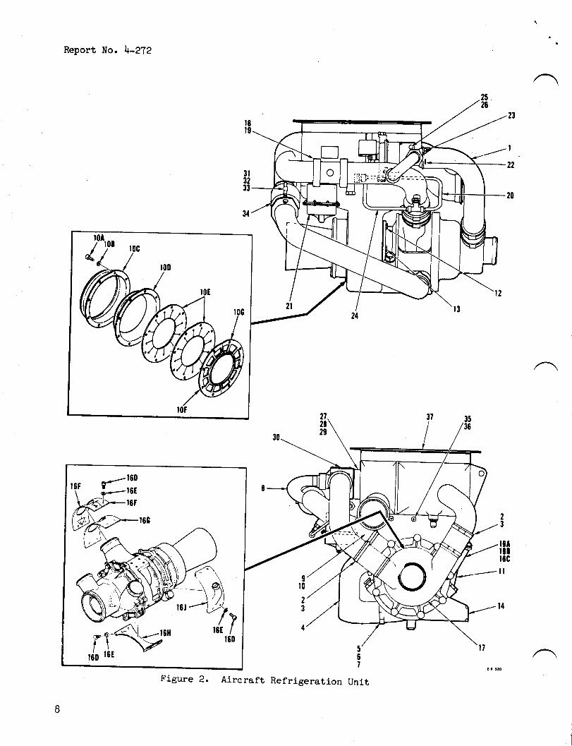
Report No. l+-272
IEt9
3t3233
34
23
I
22
20
23
t8tr8tr8c
tl
t4
Figure 2. Aircraft Refrigeration Unit
8
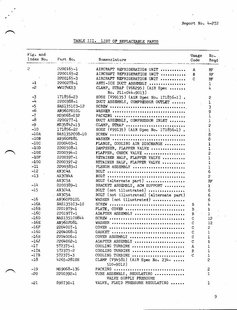
Report No. \-272
TABLE III. LIST OF REPLACEABTE PARTS
-
l'ig. andIndex No. Part No. Nomencl-ature
Usage No.Code Reqd
,r20015>-r22OOt5r-222oOL65-322OO2T8-Ll.lWDTl+KS3
rT1816-232200388-1NAS1351C3-12Arrg50PDrotr,tsgo58-032220O2TT-LMS358h2-13LTl^856-22NAS1352C08-10Ar{g50PD8r22001+03-12200508-12200394-1?200397-r2200397-22200383-1AN3C\AA1{3CH\AAN3C'A2200389-1AN3C4AAN3C'AAN960PD10tNAS135lC3-1022or9T9-L22OrgTT-LNAS1351C08U+ANg60PDSL22OI+007-I2201+008-1220ll005-12201+062-L57237'-I,T23Tr-2572375-3l+265-2B1sH
MS9068-1362200392-r
B9BT3o-1
AIRCRAFT RII'RIGERATION UNITAIRCRAT'T REFRIGERATION UNITAIRCMFT REFRIGEMTION UNITAMI-ICE DUCT ASSE,IBLYcI"Al,tP, STRAP (V66Zg>) (ain spec . o.....
No. 211-0hl+-9013 )HOsE (v99135 ) (Rin spc No. U1855-1) .DUCT ASSEI,tsLY, COI,IPRESSOR OUILET ... o..SCREW ...o....o. .............o....WASHER ......o.a.......................PACICING .... o. o........ .......... ......DUCT ASSEMBLY, C${PRESSoR INLET .......CIrAl,lPr STRAP ... ............ ..... o.....IrosE (v99135) (AiR spec No. 1?1855-1) .SCREW .o.....o.. ......r....o.WASHER .........r ............FLANGE, COOLING AIR DISCHARGE qo..o....DAI4PENER, FLAPPER VALVE ....... o.o.....FLAPPER, CHECK VALVE ....r.............RETAINER HALF, FLAPPER VALVE ..........RETAINER HALF, Fl,AppER VAIVE ..... o....PLENUI,I ASSEMBLY . . o... o.... ., r.. r.BOLT .o....o.... .......o..BOLT ........... .....o.......BOIT (alternate part) oo...............BRACKET ASSEI,IBLY, ACM SUPPORT ....o....BOLT (not illustrated) ..............t.BOLT (not illustrated) (alternate part)WASHER (not illustrated) ........,.....SCREW o....o.... ........PLATE, COVM
aaaaaaaaaaa
AB
c
RF
RF
RF
1\
21
39112I88112I1162RF
1566l+
'l
1
12T22I'l
'l
I112
21
-1-2
-3-4-,-6
.f
-8-9-10-10A-l0B-10c-10D-l0E-l0F-10G-11-L2-t<
-14-15
-ro-164-J_OlJ
-J.OU
-16D-r6E-16F-16o-16H-16I
-r l}r-17B-18
BBBf
rt
rr
ttIf
ABc
-19-20
-2L
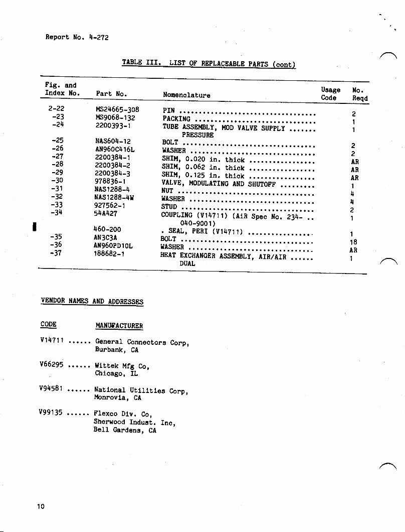
Report No. 4-272
Flg. andIndex No. Part No. Nonenclature
UsageCode
No.Reqd
2-22_23
-24
Irs24655-308t{s9058-1322200393-1
NAS604-12AN960C416L2200384-12200384-22200384-3978830-tNAS1288-4NAS1288-4r{927562-154A427
450-200AN3C3AAN96OPDlOL188682-1
PIN .............o..................... zPACKIIfG ............ o. o................ ITUBE ASSEUBLY, uoD VALVE SUppLy ......o I
-25-26_27
-28_29
-30-3t-32-33-34
-35-35-37
PRESSUREBOLT .............o......a.........a...WASHER ...o............................SHIMr 0.020 ln. thlck ............ o. o..SHIM, 0.062 in. thlck .......o.........SHIM, 0.125 in. thlck ....o............VALVE, MoDULATING AND SHUTOFF .........NUT ...............a....o..............hIASHER ..... o......... o... o............STUD ..o.o............o..............o.COUPLING (Vl47il) (AlR Spec No. 2J4_ ..
040-900 1 )
22AN
AR
AR
1
4421
. SEAL, pBnr (v14?1 1) ................ - 1BOLT ........................o....o.... lEI{ASHER ..... r.......... o...... o........ ARHEAT EXCHANCER ASSEttsLy, AIn/AIR ...... 1
DUAL
VENDON NAMES AND ADDRESSES
CODE
v1471 1 ......
v66295 .. o...
v94581 . o....
v99135 ......
I.{ANtlSACTUnEn
General Connectors Corp,Burbank, CA
l{ittek Mfg Co,Chlcago, IL
Natlonal Utllltles Corp,Monrovla, CA
Flexco Dlv. Co,Sherwood fndust. Inc,Bell Gardens, CA
10
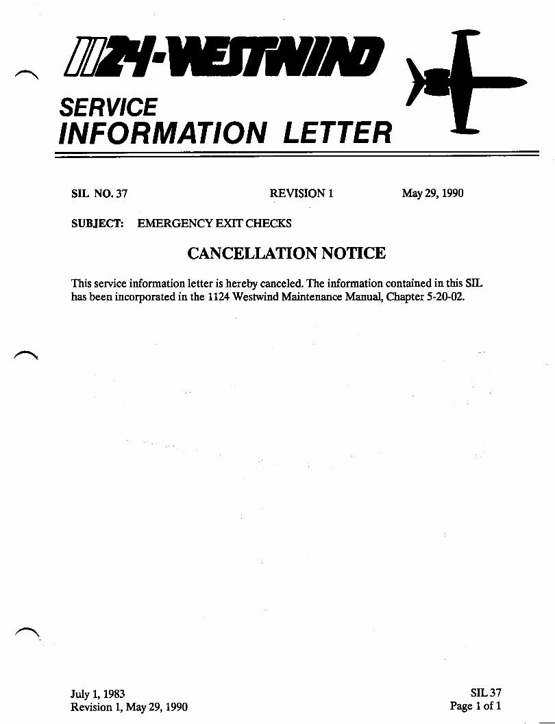
TWTSERY'CEINFORMATION LETTER
srl, No.37 REVISION 1 May29, L990
SUBJECT: EMERGENCY E)ilT CHECKS
CANCELI,ATION NOTICE
This service information letter is hereby canceled. The information contained in this SILhas been incorporated in the 1124 Westwind Maintenance Manual, Chapter 5-20-W.
July 1, 1983Revision 1, May 29,t990
SIL37Page 1. of 1
TWISERY'CEINFORMATION LETTER
S I L NO. 37
SUBJECT: EMERGENCY EXIT CHECKS ,ffJuly 1, 1983
Chapter 5 of the LL24/LL24A Maintenance lttanual , in 5-20-00 page 21,0item (10) requires that the energency exit seal be cleaned andlubricated at each 150 hour interval.It has come to IAIITs attention that some operators may not beacconpli-shing the 150 hour cleaning and lubrication due to thedifficulty in reinstalling the emergency exit and the possibil-ity of pressurizatton leaks after the exit has been removed.Keeping the seals clean and lubricated will prevent the sealfrom sticking and being damaged during removal of the emergencyexit.Flight crew members nay wish to accomplish the exit removal toassure their proficency and farniliarity with the procedure.Complying with the required exit removal schedule will alsoassure that there will be no problem should an emergency occur.
CAUTIONFlush adjustmen-t of the emergency exittrim panel, 4t the top edge could resultin the trin panel catching under themetal cornice thereby restricting rbnovalof the emergency exit. To assure trimpanel does not catch under edge of cornicespacers may be added as necessay underthe wood strip containing trirn retentionmagnets.
/@lfilvmrw*!!E;,^.*
SUBSIDIARY OF ISRAEL AIRCRAFT INDUSTRIES, LTD.
BEN GURION AIRPORT, ISRAEL
Til}{o}\^
SERVICEINFORMATION LETTER
sIL No. 38 NOVEMBER 30, 1983
SUBJECT: INSPECTION AND SERVICE LIFE ON GAS STOMGE BOTTLESP/N 37s3015 AND 375301s-501
Important changes are being made to the inspection requirementsand life lirnits of gas storage bottles used in the thrust reverserand landing gear systems.
The following requirements will appear in Revision No. LZ to theLI24 / LL74A Maintenance Manual :
.\AGas Storage Cyliner P/N 3753015(Walter Kidde P/N ?,L1'597 or P/N 240737)
Acconplish a visual inspection each year of both theexterior and interior of the bottle.Hydrostatic test bottle every three years.Bottles must be replaced after 15 years in service or20,000 pressurizatlon cycles, whichever occurs first.
NOTETime count for inspections, -testltg orreplacement shall commence from date bottlewas originally placed in service orcertification date of aircraft.
Gas Storage Cylinder P/N 3753015-501-(HTL Industries, Inc. P/t'l 36200071)
Hydrostatic test bottle every five years - Timeshall commence from date bottle was originallyin service or certi-fication date of aircraft.There is no service life linit on this bottle.should be replaced on condition.
/@ lfil w:n*s'p**r !,!#;,^n,,*
SUBSIDIARY OF ISRAEL AIRCRAFT INDUSTRIES' LTD'
BEN GURION AIRPORT, ISRAEL
a.
b.c.
a.
b.
countp laced
It
}
Related Documents