Lesson 21: Analog to Digital Conversion Objectives: (a) Describe the advantages of digital over analog communication. (b) Discuss the basic steps of the analog-to-digital conversion process: sampling, and quantizing/encoding. (c) Given an analog waveform, sampling rate, and resolution, determine the resulting quantized signal and the binary encoded A/D output. (d) Calculate the Nyquist sampling rate for an analog signal. (e) Given the number of bits in an A/D process, and sample frequency, determine the generated bit rate. (f) Define quantization error and state the ONLY way to improve it. Connection to Cyber Security In Lesson 18, you learned about modulation, and that it is impractical to transmit signals at baseband frequencies through free space. Modulation upshifts the frequency of transmission, to allow for smaller antennas. For an AM communication system, the signals at various places in the system is shown below. We could have also used FM or PM, in which case the signal that exists in the communication channel (free space) might look like the following, depending on the information signal (left: frequency modulation, right: phase modulation). In a digital communication system, the information is composed of 1s and 0s, and the information signal is composed of voltage pulses that represent the 1s and 0s. Hackers can attack our system in a number of ways, such as “reading our mail” or injecting their own information into our channel. In the digital age, cyber-attacks usually fall onto digital communication systems. But where do the 1s and 0s come from? Lesson 23 deals with how 1s and 0s are created from an analog signal. 1. Analog Systems When you look at the waveform below, you should notice that it is a signal that varies continuously in time and amplitude. If we observed nature, we would see that nature produces signals like this (i.e., changes in pressure, variations in light, sounds, etc.). Analog systems use analog electrical signals to represent these natural patterns, such as the voltage signal created from the sound waves of a person speaking into a microphone, shown in the next figure.

Welcome message from author
This document is posted to help you gain knowledge. Please leave a comment to let me know what you think about it! Share it to your friends and learn new things together.
Transcript

Lesson 21: Analog to Digital Conversion
Objectives:
(a) Describe the advantages of digital over analog communication.
(b) Discuss the basic steps of the analog-to-digital conversion process: sampling, and quantizing/encoding.
(c) Given an analog waveform, sampling rate, and resolution, determine the resulting quantized signal and the binary
encoded A/D output.
(d) Calculate the Nyquist sampling rate for an analog signal.
(e) Given the number of bits in an A/D process, and sample frequency, determine the generated bit rate.
(f) Define quantization error and state the ONLY way to improve it.
Connection to Cyber Security
In Lesson 18, you learned about modulation, and that it is impractical to transmit signals at baseband frequencies
through free space. Modulation upshifts the frequency of transmission, to allow for smaller antennas. For an AM
communication system, the signals at various places in the system is shown below.
We could have also used FM or PM, in which case the signal that exists in the communication channel (free space)
might look like the following, depending on the information signal (left: frequency modulation, right: phase
modulation).
In a digital communication system, the information is composed of 1s and 0s, and the information signal is
composed of voltage pulses that represent the 1s and 0s. Hackers can attack our system in a number of ways, such as
“reading our mail” or injecting their own information into our channel. In the digital age, cyber-attacks usually fall
onto digital communication systems. But where do the 1s and 0s come from? Lesson 23 deals with how 1s and 0s
are created from an analog signal.
1. Analog Systems
When you look at the waveform below, you should notice that it is a signal that varies continuously in time and
amplitude. If we observed nature, we would see that nature produces signals like this (i.e., changes in pressure,
variations in light, sounds, etc.). Analog systems use analog electrical signals to represent these natural patterns,
such as the voltage signal created from the sound waves of a person speaking into a microphone, shown in the next
figure.

What do you think might be an example of an analog system in action? How
about an 8-track tape player playing the songs on Michael Jackson’s 8-track
album, Thriller1.
This is a great example of an analog system, but my guess is you have no idea
what an 8-track is. So, let’s list some other analog systems that that may ring a
bell: AM/FM radios, rotary telephones, cassette tape players, VCRs, broadcast
TVs, the microphone you are singing into at Bancroft’s karaoke night…
So maybe you’re thinking, “I still have no idea what that stuff is!” There’s
probably a reason for that. We don’t really use many systems that are completely
analog anymore; digital communications are more widely used.
2. Digital Systems
Let’s think for a second about comparisons between what was used in the past and what you use now:
Type of Information Past Device Present Device
Music Cassette Tape CD
Videos VHS (VCR) DVD/Blu-ray Disc
Broadcast Television Standard Definition TV High Definition TV
We want the same types of information but are using a different method to get them: digital systems. Digital systems
use electrical signals that represent discrete (often binary) values. The electrical signals are referred to as digital
signals. Specifically, binary baseband digital signals use two discrete voltage levels to represent binary 1 or 0 (bits),
as shown in the example plots below. Combining multiple bits into words permits us to represent more than just two
things. Digital circuits operate on digital signals, performing logic and arithmetic functions.
Interesting fact and important to the class: digital signals are not representative of signals that occur in nature.
Natural signals are analog, and must be converted into digital format to be used in a digital system.
Great! So we’re using a new method to get the same information. Is this a big deal? It is, because using digital
systems offers a number of advantages over using analog systems.
3. Digital Advantages
3.1 Relative noise immunity (What is the number one limiting factor in communications? Noise.)
1 Michael Jackson’s album Thriller (released in 1982) is claimed to be the Best-Selling album of all time!

Relative noise immunity is the most important advantage of digital communications
Between the transmitter and receiver, whether the system is analog or digital, noise always corrupts the transmitted
signal. In general, an analog receiver has no idea what the received signal is supposed to be after it has been
corrupted by noise, but a digital receiver only has to decide between a finite set of choices: for example, a binary
digital system’s receiver must only decide at any time whether or not it is receiving a binary 0 or a binary 1. This
means that receiver circuitry can be designed to distinguish between a 0 and 1 even in the presence of a significant
amount of noise. It is possible that the noise could be severe enough that the receiver gets confused, and incorrectly
decides it is receiving a 0 when it should be deciding a 1 (or vice versa)…these are referred to as bit errors. But in
general, digital systems are much better in noisy environments.
In long distance digital communications, digital signals can be stripped of any noise in a process called signal
regeneration. Consider a long distance transmission that incorporates a set of relay stations in order for the signals to
move from transmitter to receiver, such as what is used to connect the east coast of the US to the west coast.. Relay
stations are needed because the farther a signal travels, the weaker it gets; to make it to its destination, it must be
amplified and retransmitted at the relay stations. The relay stations that accomplish signal regeneration are called
regenerative repeaters.
If this was an analog system, the analog signal is received, amplified and retransmitted at each station. However,
noise is now a part of the signal, and so is also amplified at each station.
In a digital communication system, a digital signal is received (receiver decides 0s or 1s), regenerated (digital signal
recreated based on the 0s and 1s), and then retransmitted at each station. With signal regeneration, the noise can be
eliminated at each station. This can only be done in digital communication systems.
3.2 Error detection/correction Digital signal processing (DSP) techniques allow the detection and correction of bit
errors. Even if a digital signal contains bit errors, many of these errors can be fixed at the receiver through the use of
error correcting codes. Error correcting codes allow, for example, CDs with minor scratches to be played without
errors. Analog systems cannot detect or correct errors.
3.3 Easier multiplexing Multiplexing is the process of allowing multiple signals to share the same transmission
channel. For example, digital telephony allows carrying 24 phone conversations on a single wire (called a T1 line) at
the same time. Digital signal processing techniques enable this.
3.4 Easier to process and store Since computers store and use digital data, digital signals can be easily processed
by computers. Similarly, the digital format lends itself to easier storage of communication signals (e.g., smaller
storage footprint). DSP allows operations such as filtering, equalization and mixing to be done in software without
the use of analog circuits. DSP also permits data compression (transforming signals so that fewer bits are needed to
represent them). An example of DSP would be Garage Band, for you musicians, or photo editing software like
Adobe Photoshop, for those with a knack for photography.
To emphasize this again, these advantages are huge. This is such a big deal that even though communication
systems used to be exclusively analog, it is worth the billions and even trillions of dollars that the government and
private sector are spending to migrate communication systems to digital. In contrast, some disadvantages include:
bandwidth is about twice that of analog, and circuitry is more complex, but generally smaller and less expensive.
4. Conversion from Analog to Digital (A/D)
If nature produces analog signals, how do we create digital signals from them? Before we can use digital
transmission, we must convert the signal of interest into a digital format. The natural signal (e.g., speech) that we
want to transmit will be acquired using an analog device. The analog signal will be translated into a digital signal

using a method called analog-to-digital (A/D) conversion. The device used to perform this translation is known as
an analog-to-digital converter or ADC. Through A/D conversion, analog signals are changed into a sequence of
binary numbers (encoded bits), from which the digital signal is created by the transmitter. This process is depicted
below.
There are two major steps involved in converting an analog signal to a digital signal represented by binary numbers:
sampling, and quantizing/encoding.
Steps for A/D conversion:
4.1 Sampling This is a process of inspecting the value (voltage) of an analog signal at regular time intervals. The
time between samples is referred to as the sample period (T, in seconds), and the number of samples taken per
second is referred to as the sample frequency (fs, in samples/second or Hz). Basically, sampling is taking snap-shot
values of the analog signal so that you have an accurate representation of how the analog signal is changing over
time.
The receiver must convert the bits it receives into sample values, and then recreate what it thinks the analog signal
looks like from the samples alone. As you might deduce from the figure below, when the samples are closer together
(smaller sample period, which means higher sample frequency), the analog signal is more accurately represented.
Note that with the lower sample rates, some of the fluctuations in the analog signal have no samples on them, so the
samples are not a good representation of the analog signal. How high does our sampling frequency fs need to be in
order to accurately represent the signal? That is, what is the minimum sample frequency for the A/D to work
properly?
We could consider taking just a few samples (i.e., using a low sampling rate), which means less information to
transmit to the receiver. But if we choose that option, when we reconstruct the signal, it will likely be a terrible
representation of the original. The low sampling rate will only work well for very slowly changing (low frequency)
signals. Alternatively, we could choose the highest possible sampling rate known to man, to ensure that we can
accurately capture even very fast signal fluctuations. But the higher the sampling rate, the higher the cost of the
equipment and more information must be transmitted. In addition, if we decide to record the communications our
saved files will be unnecessarily enormous.
1 1.0005 1.001 1.0015 1.002 1.0025 1.003 1.0035 1.004 1.0045 1.005-1
-0.5
0
0.5
1
Time (sec)
Vo
ltag
e (V
)
0 1000 2000 3000 4000 5000 60000
0.05
0.1
0.15
0.2
0.25
Frequency (Hz)
Vo
ltag
e (V
)
But what is “low” and what is “high”? In other words, how exactly do I go about choosing my sampling rate? In
order to accurately reconstruct an analog signal from its samples, one must sample faster than the Nyquist sampling
rate (also called the Nyquist rate), fN, given by the formula
𝑓𝑁 = 2𝑓𝑚𝑎𝑥, where fmax is the highest frequency component of the analog signal.
That is, the sampling frequency must be more than twice the value of the highest frequency component of the signal:
, where fN = 2fmax
If the sample rate is not greater than the Nyquist rate, a problem called aliasing results, which can cause severe
distortion of your signal.
The Nyquist sample rate is a floor on the sampling rate, and practical systems sample greater than the Nyquist rate.
Some examples of common sample rates are:
Signal Signal frequency range Standard Sample Rate
Voice 300 Hz-3 kHz 8 kHz
Music 0-20 kHz 44.1 kHz (CD-quality)
Music 0-20 kHz 192 kHz (DVD-quality)
Practice Problem 23.1
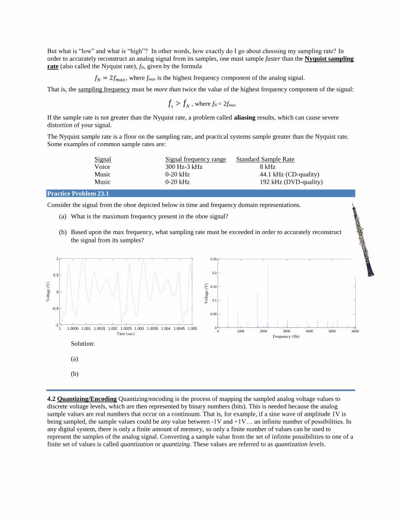
Consider the signal from the oboe depicted below in time and frequency domain representations.
(a) What is the maximum frequency present in the oboe signal?
(b) Based upon the max frequency, what sampling rate must be exceeded in order to accurately reconstruct
the signal from its samples?
Solution:
(a)
(b)
4.2 Quantizing/Encoding Quantizing/encoding is the process of mapping the sampled analog voltage values to
discrete voltage levels, which are then represented by binary numbers (bits). This is needed because the analog
sample values are real numbers that occur on a continuum. That is, for example, if a sine wave of amplitude 1V is
being sampled, the sample values could be any value between -1V and +1V… an infinite number of possibilities. In
any digital system, there is only a finite amount of memory, so only a finite number of values can be used to
represent the samples of the analog signal. Converting a sample value from the set of infinite possibilities to one of a
finite set of values is called quantization or quantizing. These values are referred to as quantization levels.
s Nf f
Inputs to A/D converters are limited to a specific voltage range. For the sine wave example above, we assumed that
all values of the analog input fall within a range of -1.0 to +1.0 volts (note: this is the typical voltage range of voice
or music signals on a computer, such as in .wav or .mp3 files).
A/D systems are characterized by the number of bits they have available to perform quantization. The number of bits
determines the number of quantization levels. An N-bit A/D converter has 2N quantization levels and outputs binary
words of length N (that is, it outputs N-bit values for every sample). For example, a 3-bit A/D system has 23 = 8
quantization levels, so all samples of a 1V analog signal that is input to this A/D will be quantized into one of only 8
possible quantization levels and each sample will be represented by a 3-bit digital word. In general, the A/D
converter will partition a range of voltage from some vmin to some vmax into 2N voltage intervals, each of size q volts,
where
.
Some common examples of A/D quantizing are digital telephony, which uses 8-bit A/D (28 = 256 quantization
levels), CD audio, which uses 16-bit A/D (216 = 65,536 quantization levels), and DVD audio, which uses 24-bit A/D
(224 = 16,777,216 quantization levels).
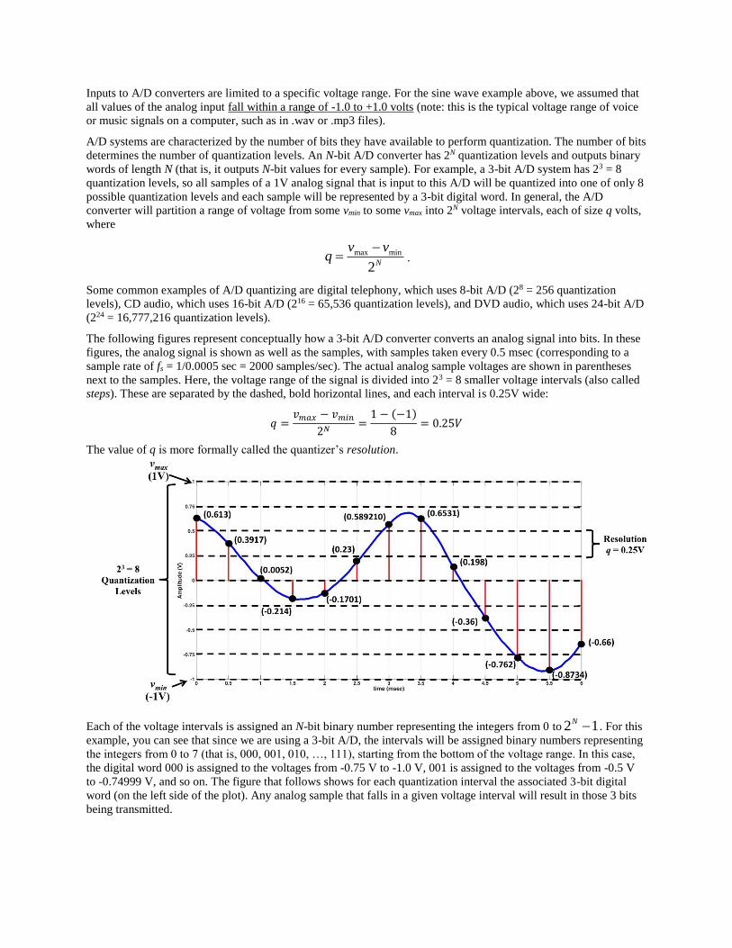
The following figures represent conceptually how a 3-bit A/D converter converts an analog signal into bits. In these
figures, the analog signal is shown as well as the samples, with samples taken every 0.5 msec (corresponding to a
sample rate of fs = 1/0.0005 sec = 2000 samples/sec). The actual analog sample voltages are shown in parentheses
next to the samples. Here, the voltage range of the signal is divided into 23 = 8 smaller voltage intervals (also called
steps). These are separated by the dashed, bold horizontal lines, and each interval is 0.25V wide:
𝑞 =𝑣𝑚𝑎𝑥 − 𝑣𝑚𝑖𝑛
2𝑁=1 − (−1)
8= 0.25𝑉
The value of q is more formally called the quantizer’s resolution.
Each of the voltage intervals is assigned an N-bit binary number representing the integers from 0 to . For this
example, you can see that since we are using a 3-bit A/D, the intervals will be assigned binary numbers representing
the integers from 0 to 7 (that is, 000, 001, 010, …, 111), starting from the bottom of the voltage range. In this case,
the digital word 000 is assigned to the voltages from -0.75 V to -1.0 V, 001 is assigned to the voltages from -0.5 V
to -0.74999 V, and so on. The figure that follows shows for each quantization interval the associated 3-bit digital
word (on the left side of the plot). Any analog sample that falls in a given voltage interval will result in those 3 bits
being transmitted.
max min
2N
v vq
2 1N
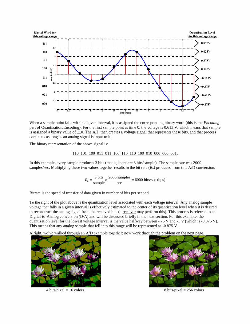
When a sample point falls within a given interval, it is assigned the corresponding binary word (this is the Encoding
part of Quantization/Encoding). For the first sample point at time 0, the voltage is 0.613 V, which means that sample
is assigned a binary value of 110. The A/D then creates a voltage signal that represents these bits, and that process
continues as long as an analog signal is input to it.
The binary representation of the above signal is:
110 101 100 011 011 100 110 110 100 010 000 000 001.
In this example, every sample produces 3 bits (that is, there are 3 bits/sample). The sample rate was 2000
samples/sec. Multiplying these two values together results in the bit rate (Rb) produced from this A/D conversion:
3 bits 2000 samples6000 bits/sec (bps)
sample secbR
Bitrate is the speed of transfer of data given in number of bits per second.
To the right of the plot above is the quantization level associated with each voltage interval. Any analog sample
voltage that falls in a given interval is effectively estimated to the center of its quantization level when it is desired
to reconstruct the analog signal from the received bits (a receiver may perform this). This process is referred to as
Digital-to-Analog conversion (D/A) and will be discussed briefly in the next section. For this example, the
quantization level for the lowest voltage interval is the value halfway between -.75 V and -1 V (which is -0.875 V).
This means that any analog sample that fell into this range will be represented as -0.875 V.
Alright, we’ve walked through an A/D example together; now work through the problem on the next page.
4 bits/pixel = 16 colors 8 bits/pixel = 256 colors
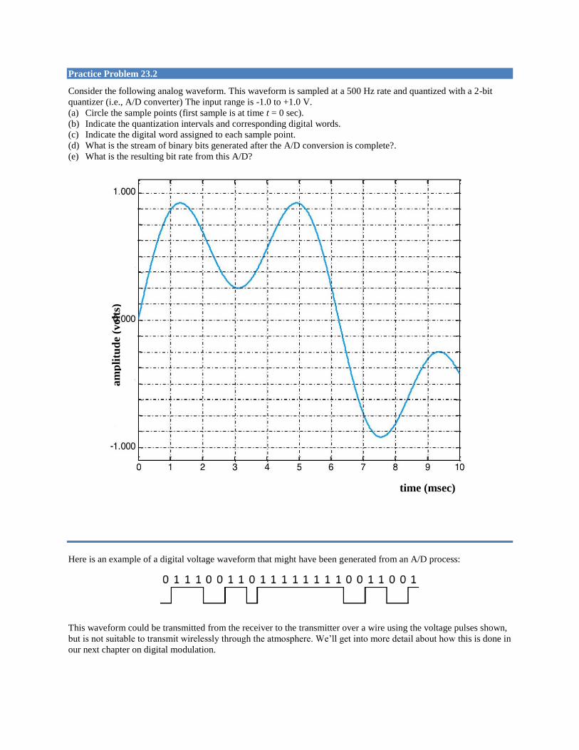
Practice Problem 23.2
Consider the following analog waveform. This waveform is sampled at a 500 Hz rate and quantized with a 2-bit
quantizer (i.e., A/D converter) The input range is -1.0 to +1.0 V.
(a) Circle the sample points (first sample is at time t = 0 sec).
(b) Indicate the quantization intervals and corresponding digital words.
(c) Indicate the digital word assigned to each sample point.
(d) What is the stream of binary bits generated after the A/D conversion is complete?.
(e) What is the resulting bit rate from this A/D?
Here is an example of a digital voltage waveform that might have been generated from an A/D process:
This waveform could be transmitted from the receiver to the transmitter over a wire using the voltage pulses shown,
but is not suitable to transmit wirelessly through the atmosphere. We’ll get into more detail about how this is done in
our next chapter on digital modulation.
time (msec)
am
pli
tud
e (v
olt
s)
To give you an idea of how quantization affects a digital picture, here’s a comparison of quantizing the same scene
with 4 bits per pixel (16 levels) and with 8 bits per pixel (256 levels). Look at a color display of this picture (such as
the picture in the pdf file of this page in the notes posted on the course website). See the difference?
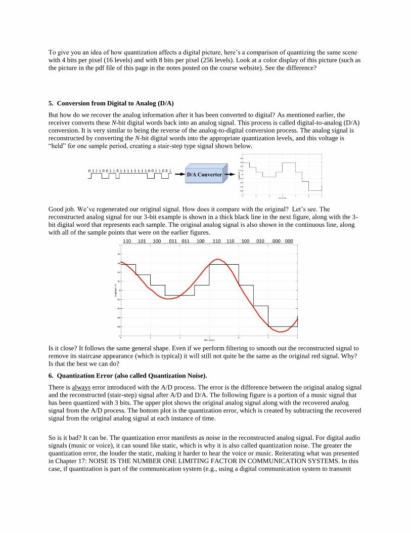
5. Conversion from Digital to Analog (D/A)
But how do we recover the analog information after it has been converted to digital? As mentioned earlier, the
receiver converts these N-bit digital words back into an analog signal. This process is called digital-to-analog (D/A)
conversion. It is very similar to being the reverse of the analog-to-digital conversion process. The analog signal is
reconstructed by converting the N-bit digital words into the appropriate quantization levels, and this voltage is
“held” for one sample period, creating a stair-step type signal shown below.
Good job. We’ve regenerated our original signal. How does it compare with the original? Let’s see. The
reconstructed analog signal for our 3-bit example is shown in a thick black line in the next figure, along with the 3-
bit digital word that represents each sample. The original analog signal is also shown in the continuous line, along
with all of the sample points that were on the earlier figures.
Is it close? It follows the same general shape. Even if we perform filtering to smooth out the reconstructed signal to
remove its staircase appearance (which is typical) it will still not quite be the same as the original red signal. Why?
Is that the best we can do?
6. Quantization Error (also called Quantization Noise).
There is always error introduced with the A/D process. The error is the difference between the original analog signal
and the reconstructed (stair-step) signal after A/D and D/A. The following figure is a portion of a music signal that
has been quantized with 3 bits. The upper plot shows the original analog signal along with the recovered analog
signal from the A/D process. The bottom plot is the quantization error, which is created by subtracting the recovered
signal from the original analog signal at each instance of time.
So is it bad? It can be. The quantization error manifests as noise in the reconstructed analog signal. For digital audio
signals (music or voice), it can sound like static, which is why it is also called quantization noise. The greater the
quantization error, the louder the static, making it harder to hear the voice or music. Reiterating what was presented
in Chapter 17: NOISE IS THE NUMBER ONE LIMITING FACTOR IN COMMUNICATION SYSTEMS. In this
case, if quantization is part of the communication system (e.g., using a digital communication system to transmit

analog information), then the A/D process adds even more noise to the signal as it moves from transmitter to
receiver.
So how do we reduce the quantization error and its associated noise? Quantization error can be reduced by
increasing the number of bits N for each sample. This will make the quantization intervals smaller, reducing the
difference between the analog sample values and the quantization levels. The figure below is the same analog signal
quantized with 4-bits per sample. Note the step-size is smaller than in the 3-bit plot, (½ the size), and the noise
signal is approximately ½ the amplitude of what it was with 3-bit quantization. The reconstructed signal looks much
closer to the original analog signal compared to the 3-bit A/D. It is worth noting that increasing the sampling
frequency will not reduce quantization noise, only increasing the number of quantization levels will do this.
We of course can’t use an infinite number of bits, so some quantization noise is always inevitable, but the nice thing
about the human ear/brain - sticking with the example of audio signals - is that beyond a certain number of bits for

each sample, the associated quantization noise becomes imperceptible. We just need enough bits to make the
recovered signal “good enough” (e.g., the recovered music sounds “good enough”).
Related Documents