Finalizing Design Specifications

Welcome message from author
This document is posted to help you gain knowledge. Please leave a comment to let me know what you think about it! Share it to your friends and learn new things together.
Transcript

Finalizing Design Specifications

Finalizing Design Specifications
© 2008 by Prentice Hall 2Chapter 13

© 2008 by Prentice Hall 3Chapter 13
The Process of Finalizing Design Specifications
Less costly to correct and detect errors during the design phase.
Take logical design information and turn it into a blueprint for the physical information system.

© 2008 by Prentice Hall 4Chapter 13
The Process of Finalizing Design Specifications
Can be paper-based or computer-based.
Can be written, graphical, or combination of the two.

© 2008 by Prentice Hall 5Chapter 13
The Process of Finalizing Design Specifications (Cont.)
Can be high-level broad-based or detailed as possible.
Format and amount of detail will be driven by intended audience.

© 2008 by Prentice Hall 6Chapter 13
The Process of Finalizing Design Specifications (Cont.)
Good specifications should be stated simply, completely, unambiguous, and have attributes that make requirements more understandable.

Deliverables and Outcomes for Traditional Projects A set of physical design specifications for the
entire system, including detailed specifications for each separate part of the system. Include functional descriptions for each part of the
system. input received and output generated for each
program and its component parts.
© 2008 by Prentice Hall 7Chapter 13

Deliverables and Outcomes for Traditional Projects (Cont.) Complete design specification is
comprehensive. Design specifications can be based on:
Traditional methods. Agile methodologies (eXtreme programming).
© 2008 by Prentice Hall 8Chapter 13
© 2008 by Prentice Hall 9Chapter 13
Specification Documents
Contains: Overall system description. Interface requirements. System features. Nonfunctional requirements. Other requirements. Supporting diagrams and models.
Specification Documents (Cont.) Computer-based requirements management
tools make it easier to keep documents up to date, add additional requirements and link related requirements.
© 2008 by Prentice Hall 10Chapter 13

Specification Documents (Cont.)
© 2008 by Prentice Hall 11Chapter 13
Figure 13-3 A screen from DOORS© Enterprise Requirements Suite(a product of Telelogic AB)

Specification Documents (Cont.)
© 2008 by Prentice Hall 12Chapter 13
Figure 13-4 A screen from Compuware Optimal Trace requirements management and definition solution

© 2008 by Prentice Hall 13Chapter 13
Structure Chart Structure Chart: a hierarchical diagram that
shows how an information system is organized. Shows how an information system is organized in
hierarchical models. Shows how parts of a system are related to one
another. Shows breakdown of a system into programs and
internal structures of programs written in third- and fourth-generation languages.
Structure Chart (Cont.)
Structure chart is composed of modules. Modules: a self-contained component of a
system that is defined by its function. Functions or subroutines in the resulting computer
program (COBOL, BASIC, FORTRAN). Method in object-oriented language.
© 2008 by Prentice Hall 14Chapter 13

Structure Chart (Cont.)
© 2008 by Prentice Hall 15Chapter 13
Figure 13-5 An illustration of the hierarchy of a structure chart

Structure Chart (Cont.)
Data couple: a diagrammatic representation of the data exchanges between two modules in a structure chart.
Flag: a diagrammatic representation of a message passed between two modules.
© 2008 by Prentice Hall 16Chapter 13

Structure Chart (Cont.)
© 2008 by Prentice Hall 17Chapter 13
Figure 13-6 Special symbols used in structure charts – Data couples and control flag
Structure Chart (Cont.)
© 2008 by Prentice Hall 18Chapter 13
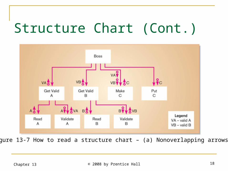
Figure 13-7 How to read a structure chart – (a) Nonoverlapping arrows
Structure Chart (Cont.)
© 2008 by Prentice Hall 19Chapter 13
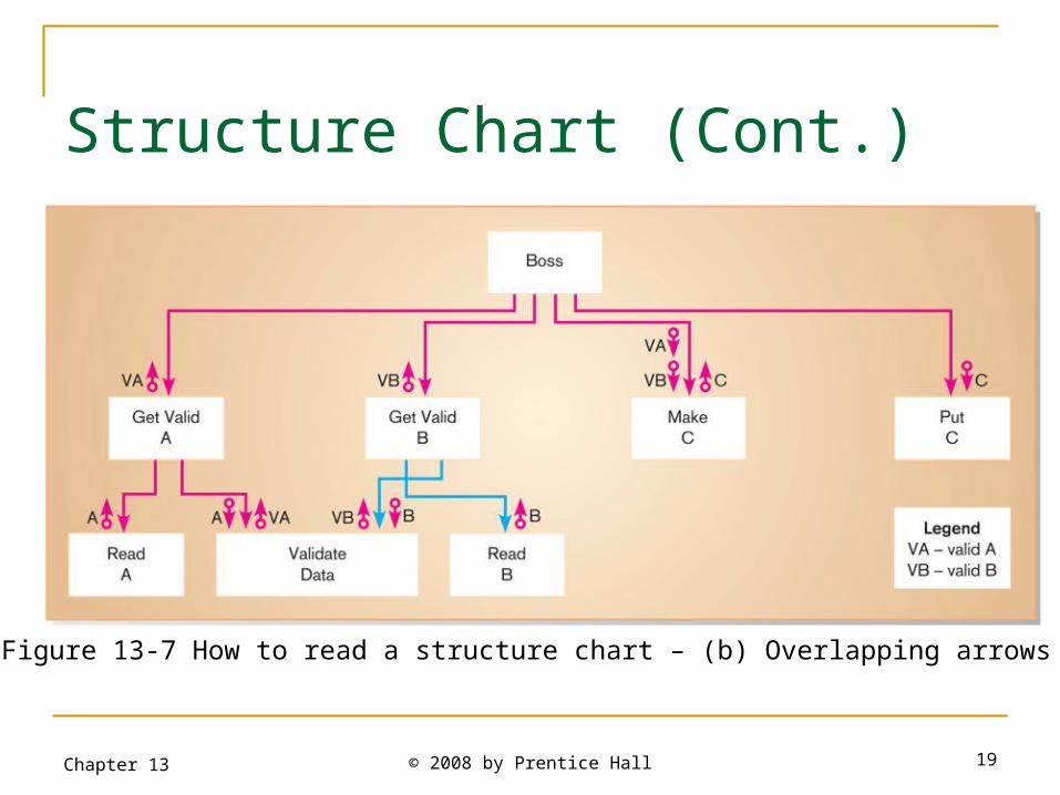
Figure 13-7 How to read a structure chart – (b) Overlapping arrows

Structure Chart (Cont.)
Serves two functions: Helps analyst think in a structured
way about the task a module is designed to perform.
Acts as a communication tool between analyst and programmer.
© 2008 by Prentice Hall 20Chapter 13
Related Documents