Chapter 11 EXTERNAL FLOW: DRAG AND LIFT Lecturer: Prof. Dong Jin Cha, PhD Department of Building and Plant Engineering Hanbat National University Fluid Mechanics: Fundamentals and Applications, 2nd Edition Yunus A. Cengel, John M. Cimbala McGraw-Hill, 2010 Lecture slides by Mehmet Kanoglu Copyright © The McGraw-Hill Companies, Inc. Permission required for reproduction or display.

Welcome message from author
This document is posted to help you gain knowledge. Please leave a comment to let me know what you think about it! Share it to your friends and learn new things together.
Transcript

Chapter 11EXTERNAL FLOW: DRAG
AND LIFT
Lecturer: Prof. Dong Jin Cha, PhDDepartment of Building and Plant Engineering
Hanbat National University
Fluid Mechanics: Fundamentals and Applications, 2nd EditionYunus A. Cengel, John M. Cimbala
McGraw-Hill, 2010Lecture slides by Mehmet Kanoglu
Copyright © The McGraw-Hill Companies, Inc. Permission required for reproduction or display.
2
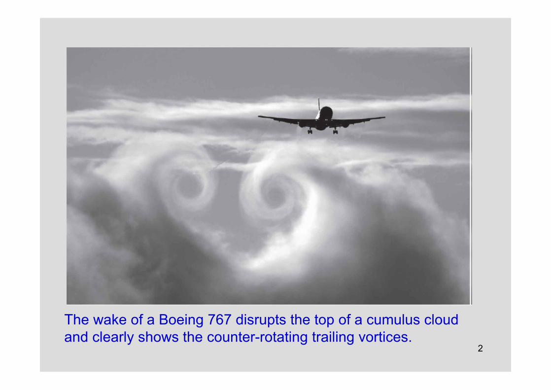
The wake of a Boeing 767 disrupts the top of a cumulus cloud and clearly shows the counter-rotating trailing vortices.

3
Objectives• Have an intuitive understanding of the various
physical phenomena associated with external flow such as drag, friction and pressure drag, drag reduction, and lift
• Calculate the drag force associated with flow over common geometries
• Understand the effects of flow regime on the drag coefficients associated with flow over cylinders and spheres
• Understand the fundamentals of flow over airfoils, and calculate the drag and lift forces acting on airfoils

4
11–1 INTRODUCTIONFluid flow over solid bodies frequently occurs in practice, and it
is responsible for numerous physical phenomena such as• the drag force acting on automobiles, power lines, trees, and
underwater pipelines;
• the lift developed by airplane wings;
• upward draft of rain, snow, hail, and dust particles in high winds;
• the transportation of red blood cells by blood flow;
• the entrainment and disbursement of liquid droplets by sprays;
• the vibration and noise generated by bodies moving in a fluid; and
• the power generated by wind turbines.
A fluid moving over a stationary body (such as the wind blowing over a building), and a body moving through a quiescent fluid (such as a car moving through air) are referred to as flow over bodies or external flow.

5
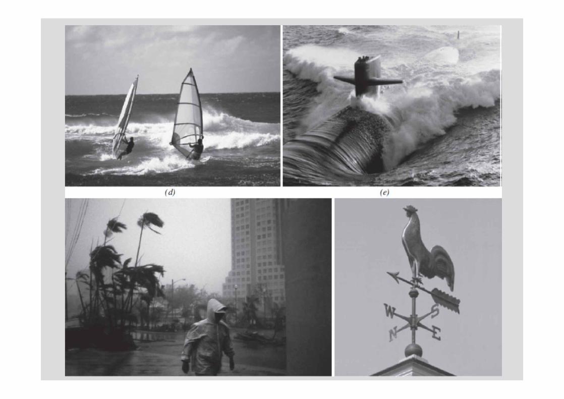
Flow over bodies is commonly encountered in practice.
6

7
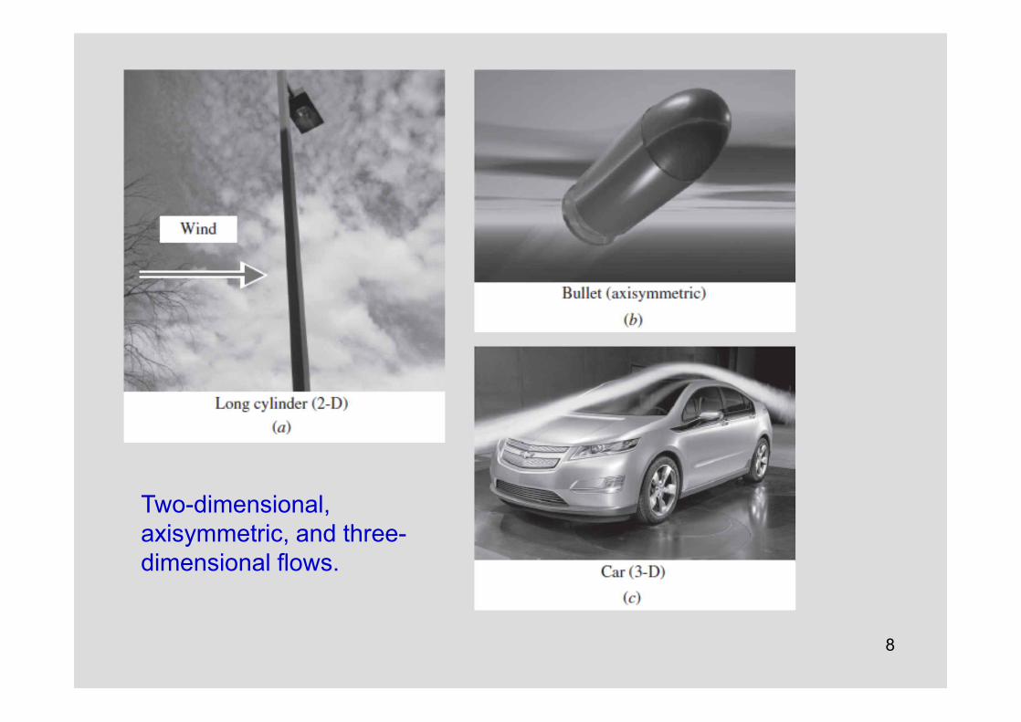
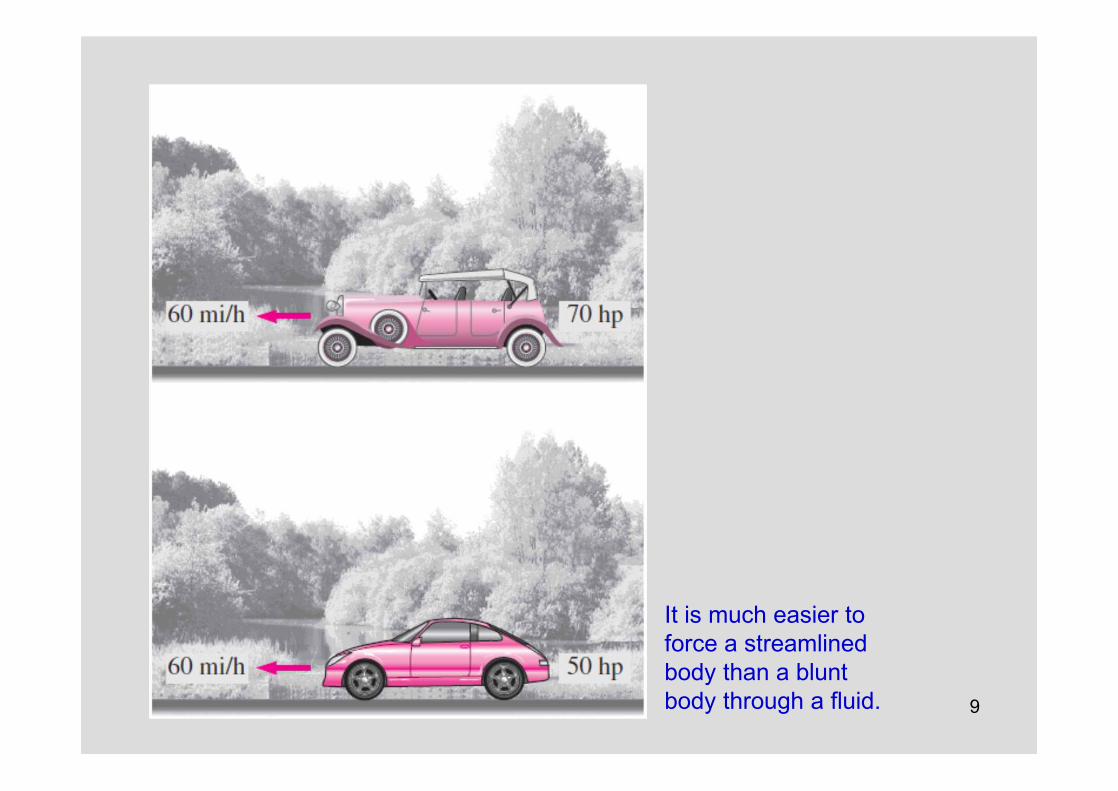
The flow fields and geometries for most external flow problems are too complicated and we have to rely on correlations based on experimental data.Free-stream velocity: The velocity of the fluid approaching a body (V or u¥ or U¥)Two-dimensional flow: When the body is very long and of constant cross section and the flow is normal to the body.Axisymmetric flow: When the body possesses rotational symmetry about an axis in the flow direction. The flow in this case is also two-dimensional.Three-dimensional flow: Flow over a body that cannot be modeled as two-dimensional or axisymmetric such as flow over a car. Incompressible flows: (e.g., flows over automobiles, submarines, and buildings) Compressible flows: (e.g., flows over high-speed aircraft, rockets, and missiles).Compressibility effects are negligible at low velocities (flows with Ma < 0.3).Streamlined body: If a conscious effort is made to align its shape with the anticipated streamlines in the flow. Streamlined bodies such as race cars and airplanes appear to be contoured and sleek. Bluff or blunt body: If a body (such as a building) tends to block the flow.Usually it is much easier to force a streamlined body through a fluid.
8
Two-dimensional,axisymmetric, and three-dimensional flows.
9
It is much easier to force a streamlinedbody than a blunt body through a fluid.
10
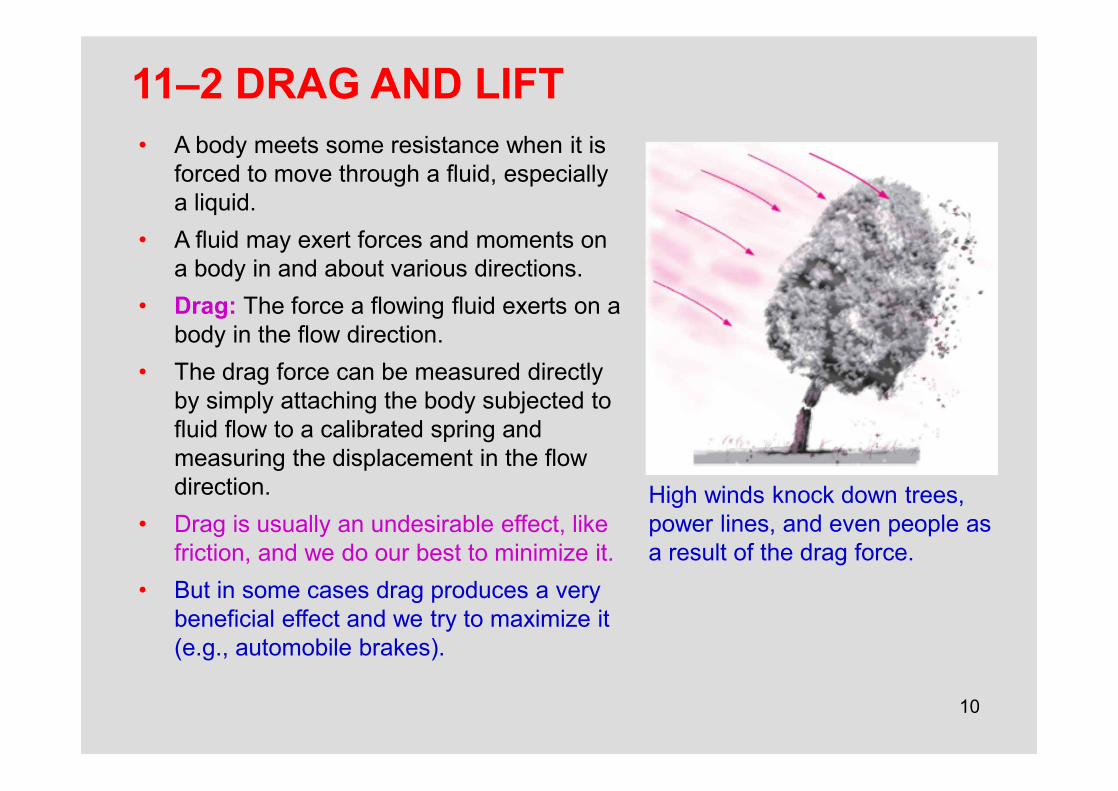
11–2 DRAG AND LIFT• A body meets some resistance when it is
forced to move through a fluid, especially a liquid.
• A fluid may exert forces and moments on a body in and about various directions.
• Drag: The force a flowing fluid exerts on a body in the flow direction.
• The drag force can be measured directly by simply attaching the body subjected to fluid flow to a calibrated spring and measuring the displacement in the flow direction.
• Drag is usually an undesirable effect, like friction, and we do our best to minimize it.
• But in some cases drag produces a very beneficial effect and we try to maximize it (e.g., automobile brakes).
High winds knock down trees, power lines, and even people as a result of the drag force.

11
Lift: The components of the pressure and wall shear forces in the direction normal to the flow tend to move the body in that direction, and their sum is called lift.The fluid forces may generate moments and cause the body to rotate. Rolling moment: The moment about the flow direction.Yawing moment: The moment about the lift direction.Pitching moment: The moment about the side force direction.
The pressure and viscous forces acting on a two-dimensional body and the resultant lift and drag forces.
12
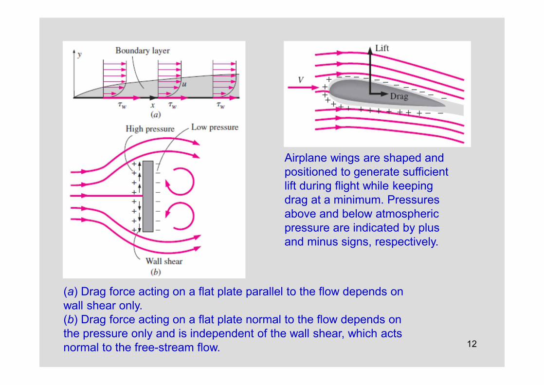
(a) Drag force acting on a flat plate parallel to the flow depends on wall shear only. (b) Drag force acting on a flat plate normal to the flow depends on the pressure only and is independent of the wall shear, which acts normal to the free-stream flow.
Airplane wings are shaped andpositioned to generate sufficient lift during flight while keeping drag at a minimum. Pressures above and below atmospheric pressure are indicated by plus and minus signs, respectively.
13
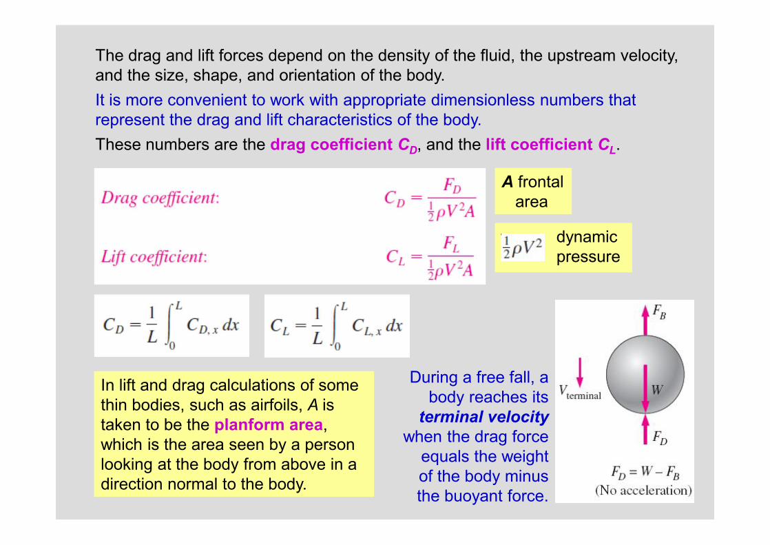
The drag and lift forces depend on the density of the fluid, the upstream velocity, and the size, shape, and orientation of the body. It is more convenient to work with appropriate dimensionless numbers that represent the drag and lift characteristics of the body. These numbers are the drag coefficient CD, and the lift coefficient CL.
During a free fall, a body reaches its
terminal velocitywhen the drag force
equals the weight of the body minusthe buoyant force.
A frontal area
dynamic pressure
In lift and drag calculations of some thin bodies, such as airfoils, A is taken to be the planform area, which is the area seen by a person looking at the body from above in a direction normal to the body.
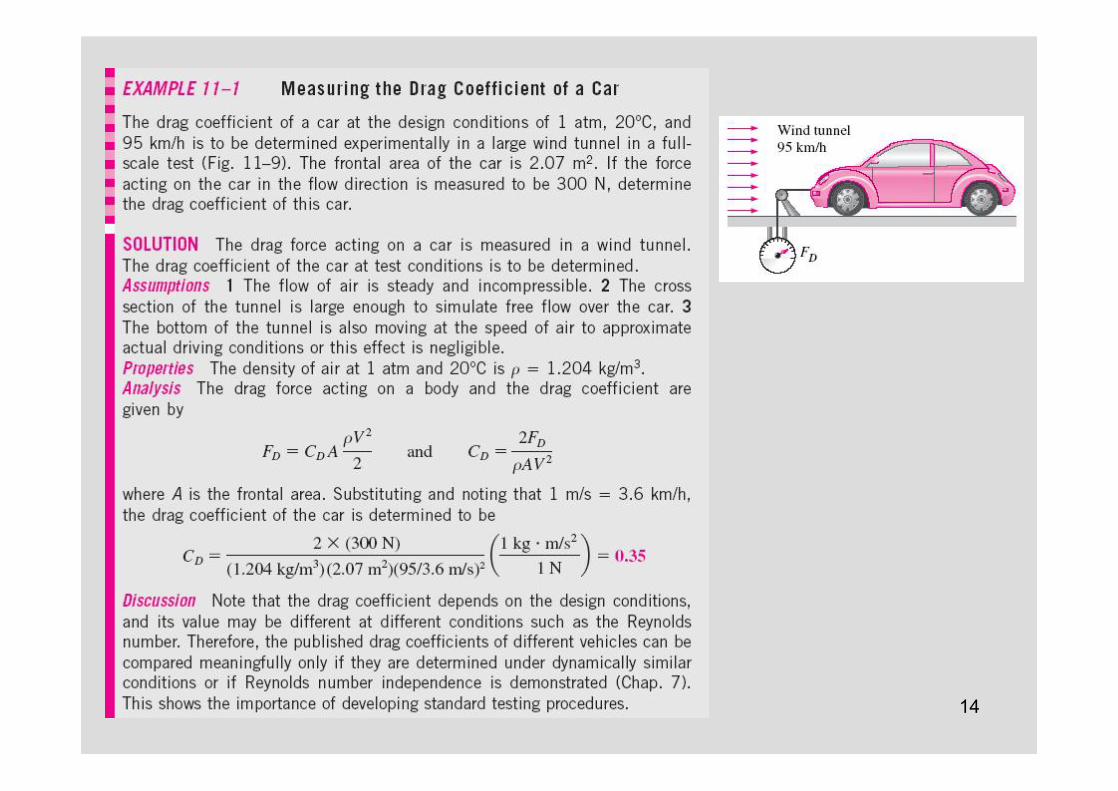
14
15
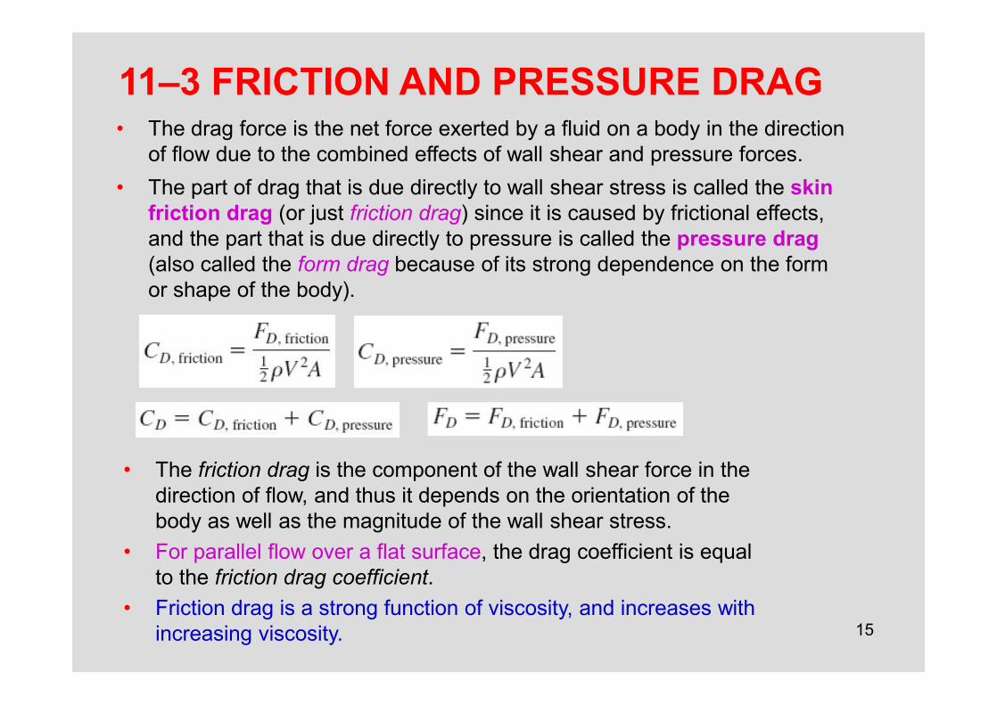
11–3 FRICTION AND PRESSURE DRAG• The drag force is the net force exerted by a fluid on a body in the direction
of flow due to the combined effects of wall shear and pressure forces.• The part of drag that is due directly to wall shear stress is called the skin
friction drag (or just friction drag) since it is caused by frictional effects, and the part that is due directly to pressure is called the pressure drag(also called the form drag because of its strong dependence on the form or shape of the body).
• The friction drag is the component of the wall shear force in the direction of flow, and thus it depends on the orientation of the body as well as the magnitude of the wall shear stress.
• For parallel flow over a flat surface, the drag coefficient is equal to the friction drag coefficient.
• Friction drag is a strong function of viscosity, and increases with increasing viscosity.
16
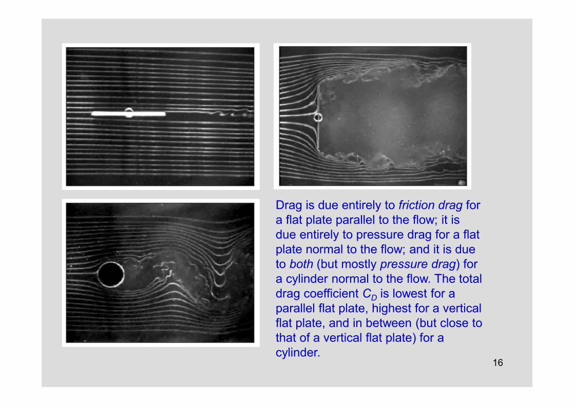
Drag is due entirely to friction drag for a flat plate parallel to the flow; it is due entirely to pressure drag for a flat plate normal to the flow; and it is due to both (but mostly pressure drag) for a cylinder normal to the flow. The total drag coefficient CD is lowest for aparallel flat plate, highest for a verticalflat plate, and in between (but close tothat of a vertical flat plate) for acylinder.

17
Reducing Drag by StreamliningStreamlining decreases pressure drag by delaying boundary layer separationand thus reducing the pressure difference between the front and back of the body but increases the friction drag by increasing the surface area. The end result depends on which effect dominates.
The variation of friction, pressure, and total drag coefficients of astreamlined strut with thickness-to-chord lengthratio for Re = 4×10⁴. Note that CD for airfoils and other thin bodies isbased on planform area rather than frontal area.
18
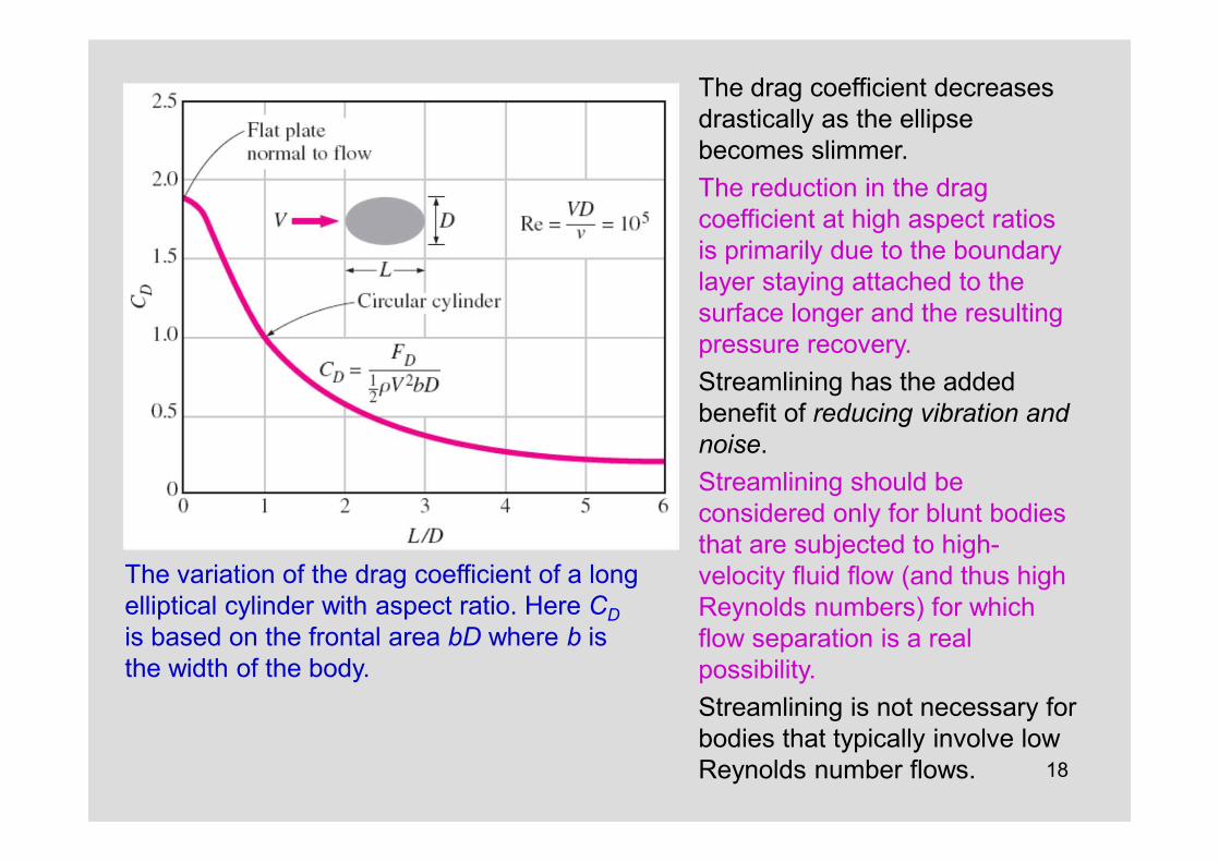
The variation of the drag coefficient of a long elliptical cylinder with aspect ratio. Here CDis based on the frontal area bD where b is the width of the body.
The drag coefficient decreases drastically as the ellipsebecomes slimmer.The reduction in the drag coefficient at high aspect ratios is primarily due to the boundary layer staying attached to the surface longer and the resulting pressure recovery.Streamlining has the added benefit of reducing vibration and noise.Streamlining should be considered only for blunt bodies that are subjected to high-velocity fluid flow (and thus high Reynolds numbers) for whichflow separation is a real possibility. Streamlining is not necessary for bodies that typically involve low Reynolds number flows.

19
Flow SeparationFlow separation: At sufficiently high velocities, the fluid stream detaches itself from the surface of the body. The location of the separation point depends on several factors such as the Reynolds number, the surface roughness, and the level of fluctuations in the free stream, and it is usually difficult to predict exactly where separation will occur.
Flow separation in a waterfall.
Flow separation over a backward-facing step along a wall.
20
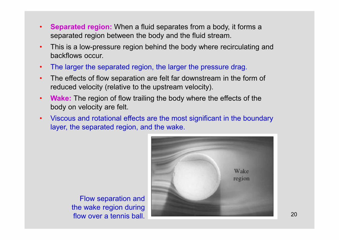
• Separated region: When a fluid separates from a body, it forms a separated region between the body and the fluid stream.
• This is a low-pressure region behind the body where recirculating and backflows occur.
• The larger the separated region, the larger the pressure drag.• The effects of flow separation are felt far downstream in the form of
reduced velocity (relative to the upstream velocity). • Wake: The region of flow trailing the body where the effects of the
body on velocity are felt. • Viscous and rotational effects are the most significant in the boundary
layer, the separated region, and the wake.
Flow separation and the wake region during flow over a tennis ball.
21
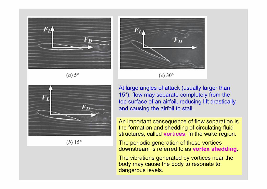
At large angles of attack (usually larger than 15°), flow may separate completely from the top surface of an airfoil, reducing lift drastically and causing the airfoil to stall.
An important consequence of flow separation is the formation and shedding of circulating fluid structures, called vortices, in the wake region. The periodic generation of these vorticesdownstream is referred to as vortex shedding.The vibrations generated by vortices near the body may cause the body to resonate todangerous levels.

22
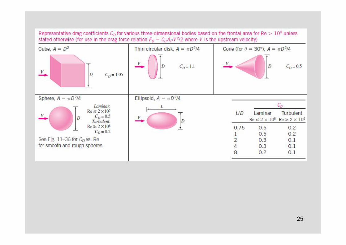
11–4 DRAG COEFFICIENTS OF COMMON GEOMETRIESThe drag behavior of various natural and human-made bodies is characterized by their drag coefficients measured under typical operating conditions.Usually the total (friction+pressure) drag coefficient is reported.
The drag coefficient for many (but not all) geometries remains essentially constant at Reynolds numbers above about 104.
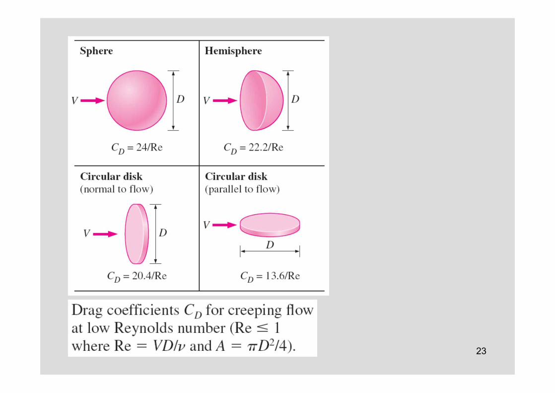
The drag coefficient exhibits differentbehavior in the low (creeping), moderate (laminar), and high (turbulent) regions of the Reynolds number.The inertia effects are negligible in lowReynolds number flows (Re < 1), called creeping flows, and the fluid wraps around the body smoothly.
Creeping flow, sphere
Stokes lawStokes law is often applicable to dust particles in the air and suspended solid particles in water.
23
24
25

26
27
28
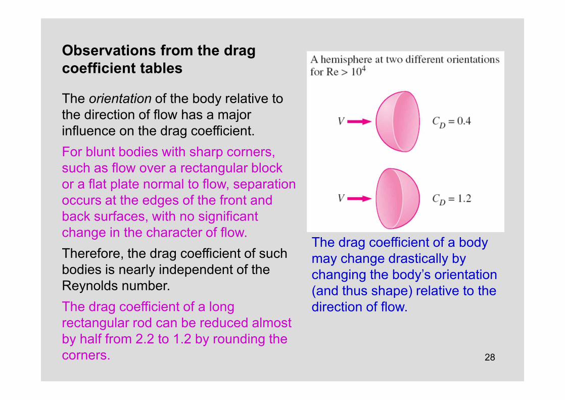
Observations from the drag coefficient tables
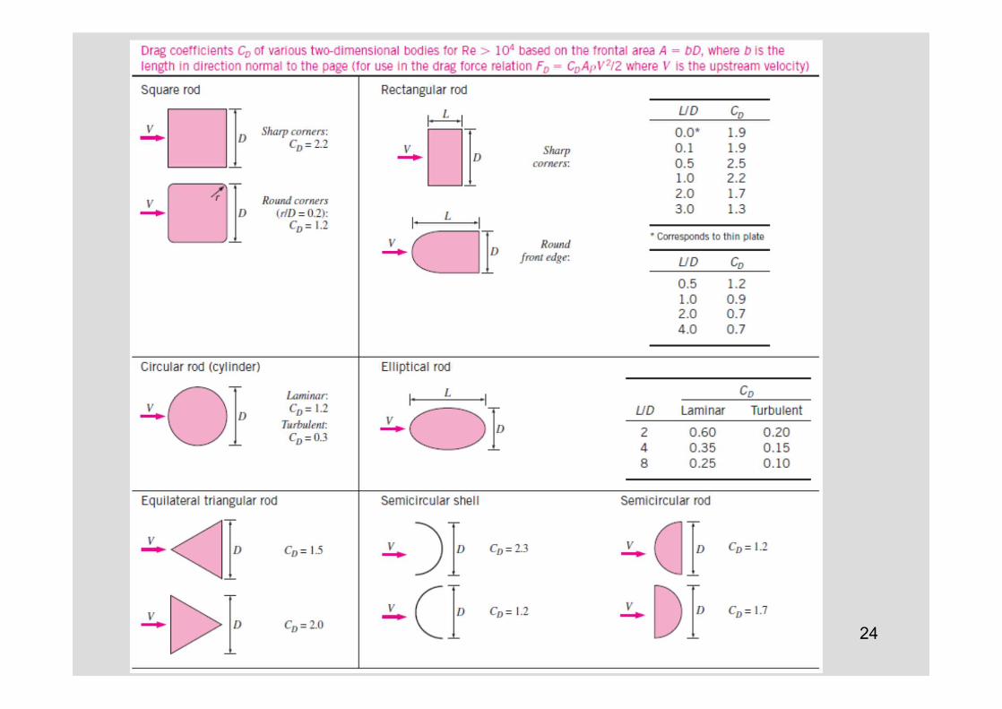
The orientation of the body relative to the direction of flow has a major influence on the drag coefficient. For blunt bodies with sharp corners, such as flow over a rectangular block or a flat plate normal to flow, separation occurs at the edges of the front and back surfaces, with no significant change in the character of flow. Therefore, the drag coefficient of such bodies is nearly independent of the Reynolds number. The drag coefficient of a long rectangular rod can be reduced almost by half from 2.2 to 1.2 by rounding the corners.
The drag coefficient of a body may change drastically by changing the body’s orientation (and thus shape) relative to the direction of flow.
29
Biological Systems and Drag
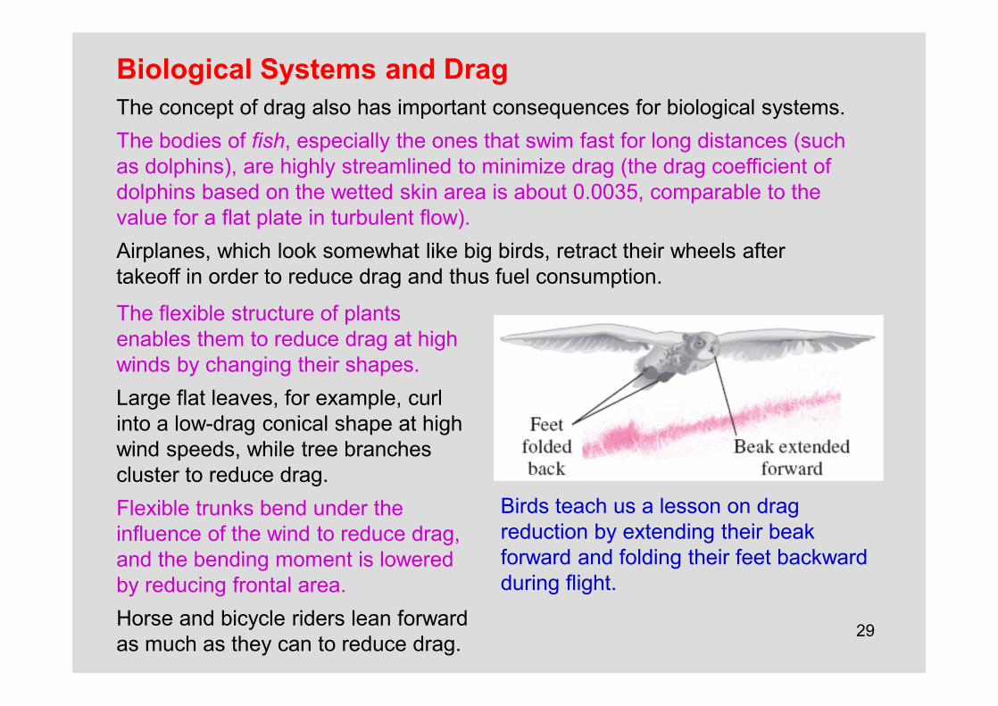
Birds teach us a lesson on dragreduction by extending their beakforward and folding their feet backward during flight.
The concept of drag also has important consequences for biological systems.The bodies of fish, especially the ones that swim fast for long distances (such as dolphins), are highly streamlined to minimize drag (the drag coefficient of dolphins based on the wetted skin area is about 0.0035, comparable to the value for a flat plate in turbulent flow). Airplanes, which look somewhat like big birds, retract their wheels after takeoff in order to reduce drag and thus fuel consumption.
The flexible structure of plants enables them to reduce drag at high winds by changing their shapes.Large flat leaves, for example, curl into a low-drag conical shape at high wind speeds, while tree branches cluster to reduce drag. Flexible trunks bend under the influence of the wind to reduce drag,and the bending moment is lowered by reducing frontal area.Horse and bicycle riders lean forward as much as they can to reduce drag.
30
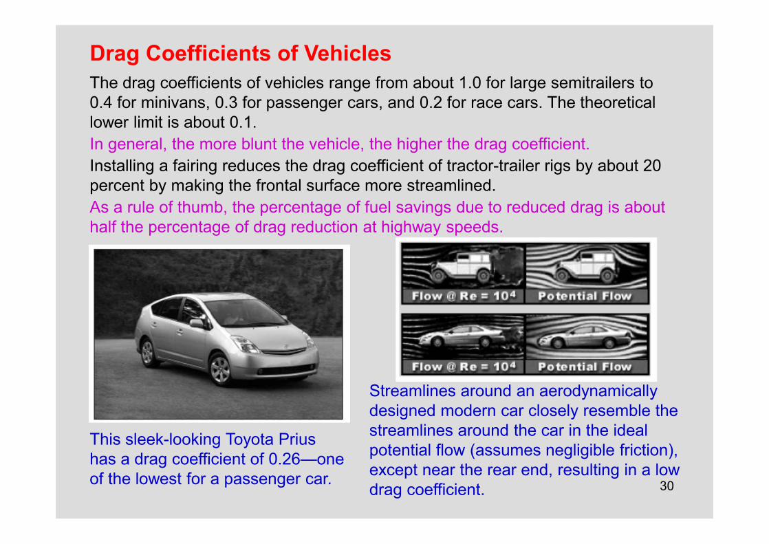
Drag Coefficients of Vehicles
This sleek-looking Toyota Prius has a drag coefficient of 0.26—one of the lowest for a passenger car.
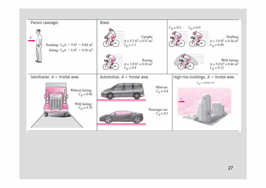
The drag coefficients of vehicles range from about 1.0 for large semitrailers to 0.4 for minivans, 0.3 for passenger cars, and 0.2 for race cars. The theoretical lower limit is about 0.1.In general, the more blunt the vehicle, the higher the drag coefficient.Installing a fairing reduces the drag coefficient of tractor-trailer rigs by about 20 percent by making the frontal surface more streamlined. As a rule of thumb, the percentage of fuel savings due to reduced drag is about half the percentage of drag reduction at highway speeds.
Streamlines around an aerodynamically designed modern car closely resemble the streamlines around the car in the ideal potential flow (assumes negligible friction),except near the rear end, resulting in a low drag coefficient.

31
The drag coefficients of bodies following other moving bodies closely can be reduced considerably due to drafting (i.e., falling into the low pressure region created by the body in front).
The aerodynamic drag is negligible at low speeds, but becomes significant at speeds above about 50 km/h.At highway speeds, a driver can often save fuel in hot weather by running the air conditioner instead of driving with the windows rolled down.The turbulence and additional drag generated by open windows consume more fuel than does the air conditioner.
SuperpositionThe shapes of many bodiesencountered in practice are not simple. But such bodies can be treated conveniently in drag forcecalculations by consideringthem to be composed of two or more simple bodies.A satellite dish mounted on a roof with a cylindrical bar, for example, can be considered to be a combination of a hemispherical body and a cylinder. Then the drag coefficient of the body can be determined approximately by usingsuperposition.

32

33

34

35
11–5 PARALLEL FLOW OVER FLAT PLATES
The development of the boundary layer for flow over a flat plate, and the different flow regimes. Not to scale.
Velocity boundary layer: The region of the flow above the plate bounded by d in which the effects of the viscous shearing forces caused by fluid viscosity are felt. The boundary layer thickness d is typically defined as the distance y from the surface at which u = 0.99V.The hypothetical curve of u = 0.99V divides the flow into two regions: Boundary layer region: The viscous effects and the velocity changes are significant. Irotational flow region: The frictional effects are negligible and the velocity remains essentially constant.
36
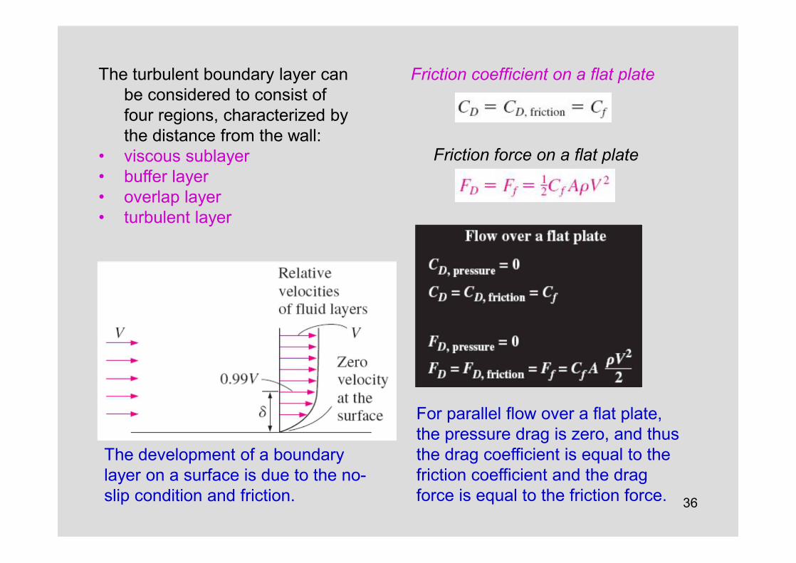
The development of a boundarylayer on a surface is due to the no-slip condition and friction.
For parallel flow over a flat plate, the pressure drag is zero, and thus the drag coefficient is equal to the friction coefficient and the drag force is equal to the friction force.
Friction coefficient on a flat plate
Friction force on a flat plate
The turbulent boundary layer can be considered to consist of four regions, characterized by the distance from the wall:
• viscous sublayer• buffer layer• overlap layer• turbulent layer
37
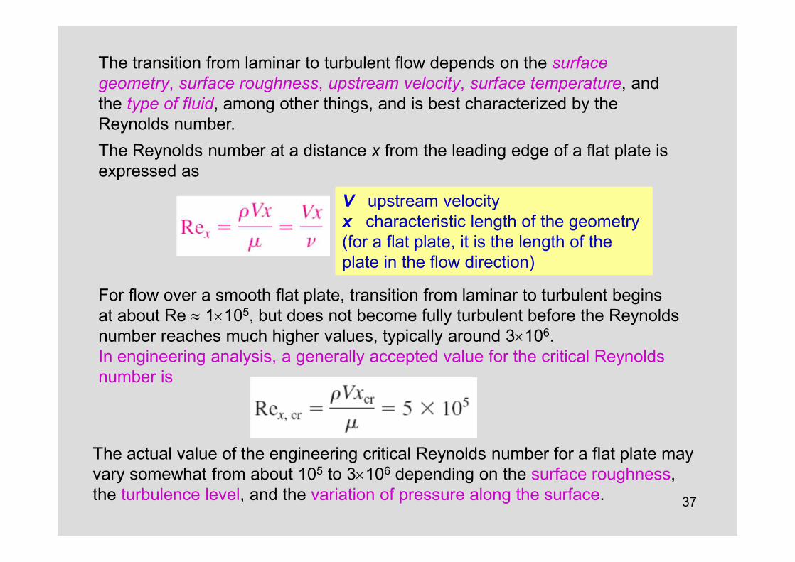
The transition from laminar to turbulent flow depends on the surfacegeometry, surface roughness, upstream velocity, surface temperature, andthe type of fluid, among other things, and is best characterized by theReynolds number. The Reynolds number at a distance x from the leading edge of a flat plate is expressed as
V upstream velocity x characteristic length of the geometry(for a flat plate, it is the length of the plate in the flow direction)
For flow over a smooth flat plate, transition from laminar to turbulent begins at about Re » 1´105, but does not become fully turbulent before the Reynolds number reaches much higher values, typically around 3´106.In engineering analysis, a generally accepted value for the critical Reynoldsnumber is
The actual value of the engineering critical Reynolds number for a flat plate may vary somewhat from about 105 to 3´106 depending on the surface roughness, the turbulence level, and the variation of pressure along the surface.
38
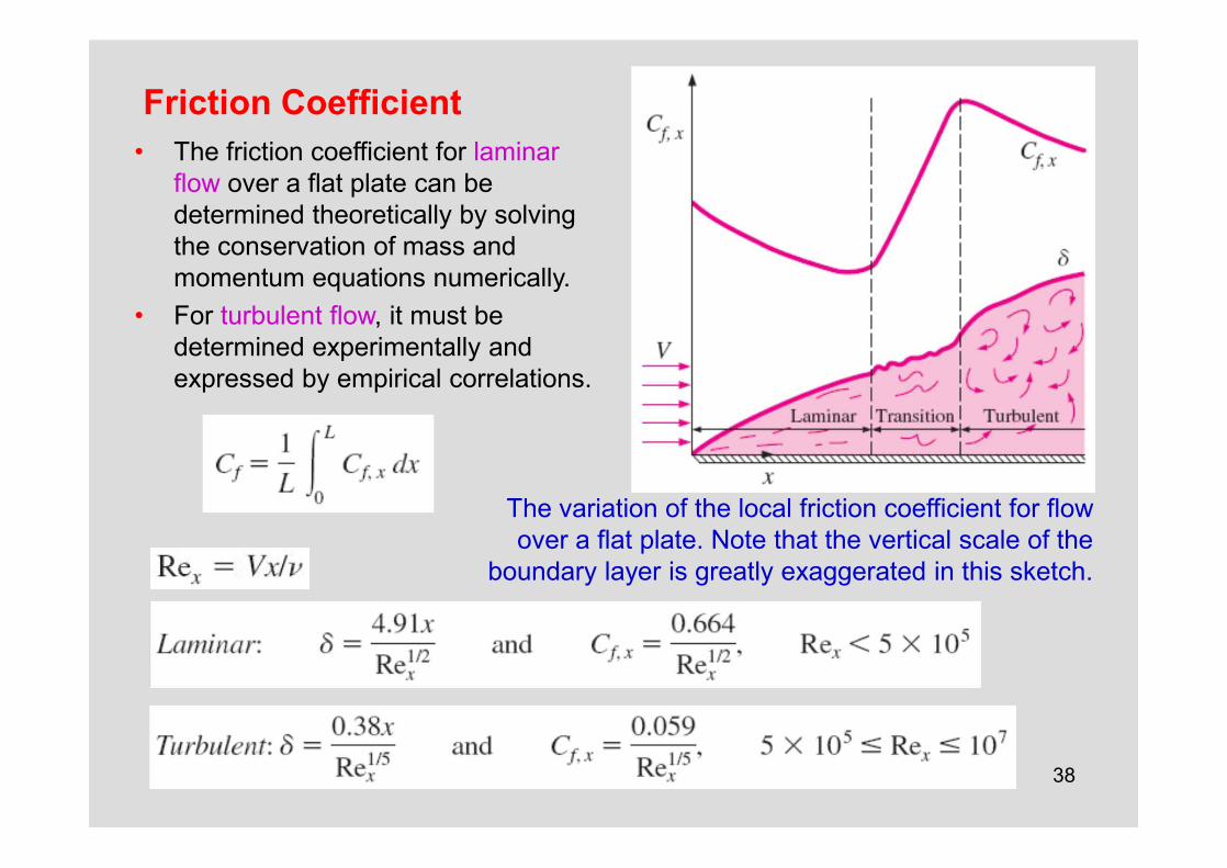
Friction Coefficient• The friction coefficient for laminar
flow over a flat plate can be determined theoretically by solving the conservation of mass and momentum equations numerically.
• For turbulent flow, it must be determined experimentally and expressed by empirical correlations.
The variation of the local friction coefficient for flow over a flat plate. Note that the vertical scale of the
boundary layer is greatly exaggerated in this sketch.

39
Average friction coefficient over the entire plate
The average friction coefficient over asurface is determined by integrating the local friction coefficient over the entire surface. The values shown here are for a laminar flat plate boundary layer.
When the laminar flow region is not disregarded
40
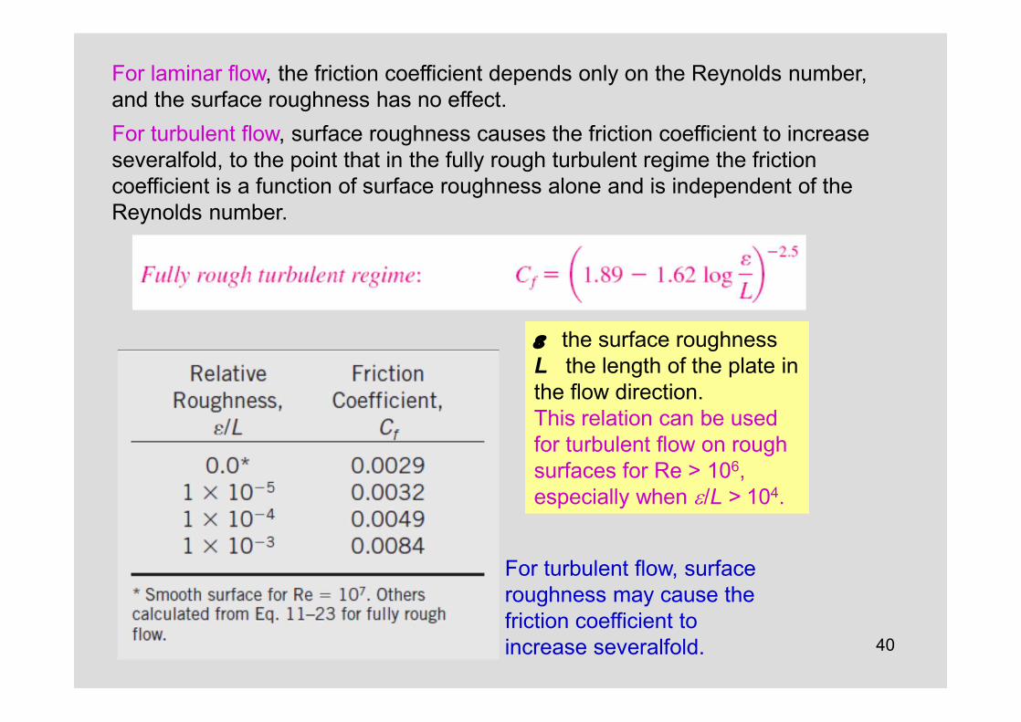
For turbulent flow, surface roughness may cause the friction coefficient toincrease severalfold.
For laminar flow, the friction coefficient depends only on the Reynolds number, and the surface roughness has no effect. For turbulent flow, surface roughness causes the friction coefficient to increase severalfold, to the point that in the fully rough turbulent regime the friction coefficient is a function of surface roughness alone and is independent of the Reynolds number.
e the surface roughness L the length of the plate in the flow direction. This relation can be used for turbulent flow on rough surfaces for Re > 106, especially when e/L > 104.
41
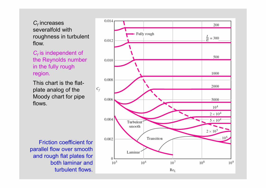
Friction coefficient for parallel flow over smooth and rough flat plates for
both laminar and turbulent flows.
Cf increases severalfold withroughness in turbulent flow.
Cf is independent of the Reynolds number in the fully rough region.
This chart is the flat-plate analog of the Moody chart for pipe flows.

42
43
44
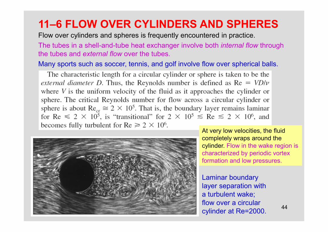
11–6 FLOW OVER CYLINDERS AND SPHERESFlow over cylinders and spheres is frequently encountered in practice. The tubes in a shell-and-tube heat exchanger involve both internal flow throughthe tubes and external flow over the tubes.Many sports such as soccer, tennis, and golf involve flow over spherical balls.
Laminar boundary layer separation with a turbulent wake; flow over a circular cylinder at Re=2000.
At very low velocities, the fluid completely wraps around the cylinder. Flow in the wake region is characterized by periodic vortex formation and low pressures.
45
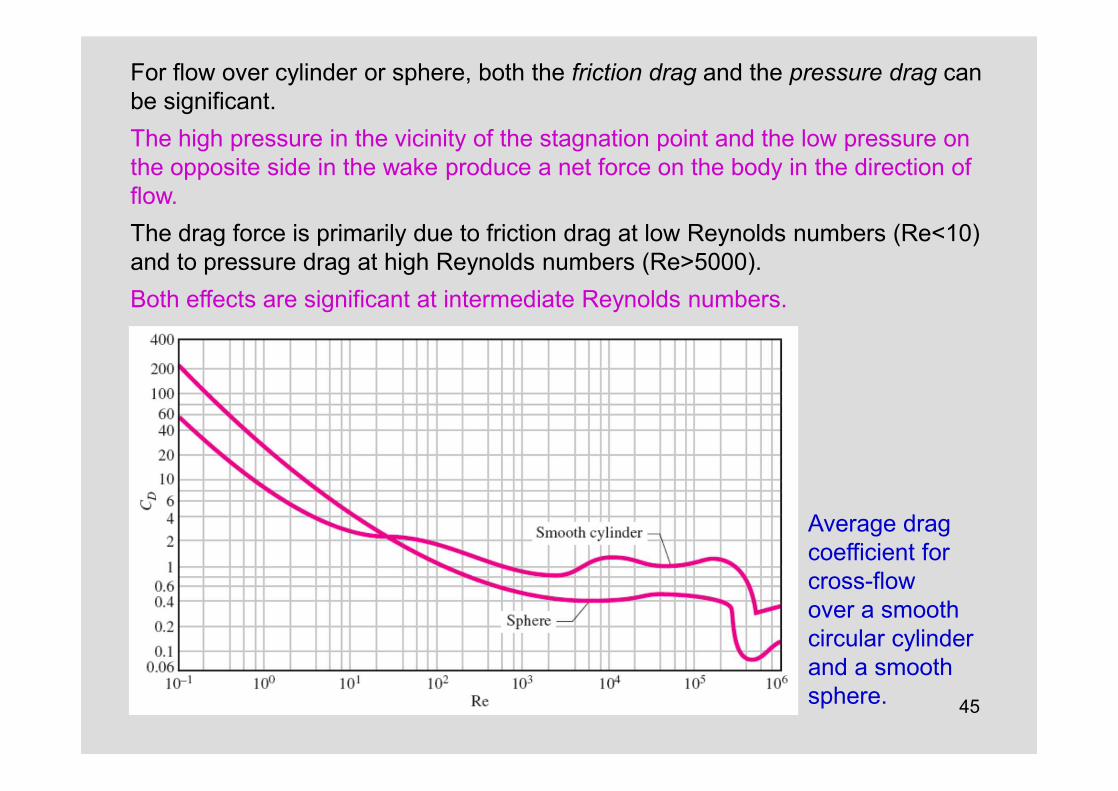
For flow over cylinder or sphere, both the friction drag and the pressure drag can be significant. The high pressure in the vicinity of the stagnation point and the low pressure on the opposite side in the wake produce a net force on the body in the direction of flow.The drag force is primarily due to friction drag at low Reynolds numbers (Re<10) and to pressure drag at high Reynolds numbers (Re>5000). Both effects are significant at intermediate Reynolds numbers.
Average drag coefficient for cross-flowover a smooth circular cylinderand a smooth sphere.

46
• For Re<1, we have creeping flow, and the drag coefficient decreases with increasing Reynolds number. For a sphere, it is CD=24/Re. There is no flow separation in this regime.
• At about Re=10, separation starts occurring on the rear of the body with vortex shedding starting at about Re=90. The region of separation increases with increasing Reynolds number up to about Re=103. At this point, the drag is mostly (about 95 percent) due to pressure drag. The drag coefficient continues to decrease with increasing Reynolds number in this range of 10<Re<103.
• In the moderate range of 103<Re<105, the drag coefficient remains relatively constant. This behavior is characteristic of bluff bodies. The flow in the boundary layer is laminar in this range, but the flow in the separated region past the cylinder or sphere is highly turbulent with a wide turbulent wake.
• There is a sudden drop in the drag coefficient somewhere in the range of105<Re<106 (usually, at about 2´105). This large reduction in CD is due to the flow in the boundary layer becoming turbulent, which moves the separation point further on the rear of the body, reducing the size of the wake and thus the magnitude of the pressure drag. This is in contrast to streamlined bodies, which experience an increase in the drag coefficient (mostly due to friction drag) when the boundary layer becomes turbulent.
• There is a “transitional” regime for 2´105<Re<2´106, in which CD dips to a minimum value and then slowly rises to its final turbulent value.
Observations from CD curves
47
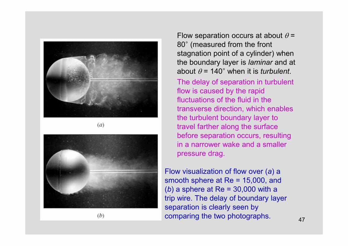
Flow visualization of flow over (a) a smooth sphere at Re = 15,000, and (b) a sphere at Re = 30,000 with a trip wire. The delay of boundary layer separation is clearly seen bycomparing the two photographs.
Flow separation occurs at about q =80° (measured from the front stagnation point of a cylinder) when the boundary layer is laminar and at about q = 140° when it is turbulent. The delay of separation in turbulentflow is caused by the rapid fluctuations of the fluid in the transverse direction, which enables the turbulent boundary layer to travel farther along the surface before separation occurs, resulting in a narrower wake and a smallerpressure drag.

48
Effect of Surface RoughnessSurface roughness, in general, increases the drag coefficient in turbulent flow.This is especially the case for streamlined bodies.For blunt bodies such as a circular cylinder or sphere, however, an increase in the surface roughness may increase or decrease the drag coefficient depending on Reynolds number.
The effect of surface roughness on the drag coefficient of a sphere.
49
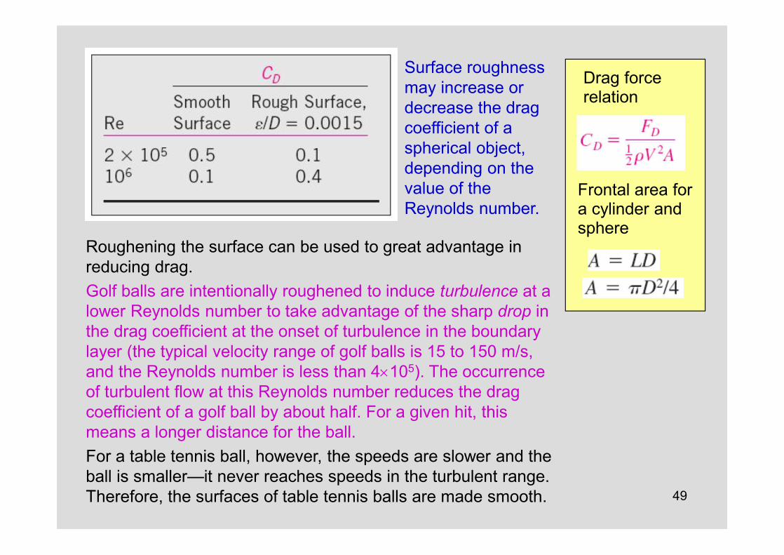
Surface roughness may increase ordecrease the drag coefficient of aspherical object, depending on thevalue of the Reynolds number.
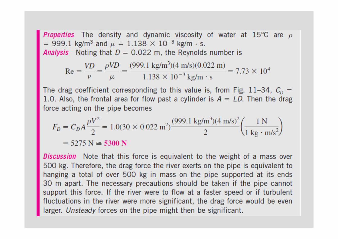
Roughening the surface can be used to great advantage in reducing drag.Golf balls are intentionally roughened to induce turbulence at a lower Reynolds number to take advantage of the sharp drop in the drag coefficient at the onset of turbulence in the boundary layer (the typical velocity range of golf balls is 15 to 150 m/s, and the Reynolds number is less than 4´105). The occurrence of turbulent flow at this Reynolds number reduces the drag coefficient of a golf ball by about half. For a given hit, this means a longer distance for the ball.For a table tennis ball, however, the speeds are slower and the ball is smaller—it never reaches speeds in the turbulent range. Therefore, the surfaces of table tennis balls are made smooth.
Drag force relation
Frontal area for a cylinder and sphere
50
51

52
11–7 LIFTLift: The component of the net force (due to viscous and pressure forces) that is perpendicular to the flow direction.
Liftcoefficient
A planform area: the area that would be seen by a person looking at the body from above in a direction normal to the body
Definition of various terms associated with an airfoil.
For an aircraft, the wingspan is the total distance between the tips of the two wings, which includes the width of the fuselage between the wings.The average lift per unit planform area FL/A is called the wing loading, which is simply the ratio of the weight of the aircraft to the planform area of the wings (since lift equals the weight during flying at constantaltitude).
53
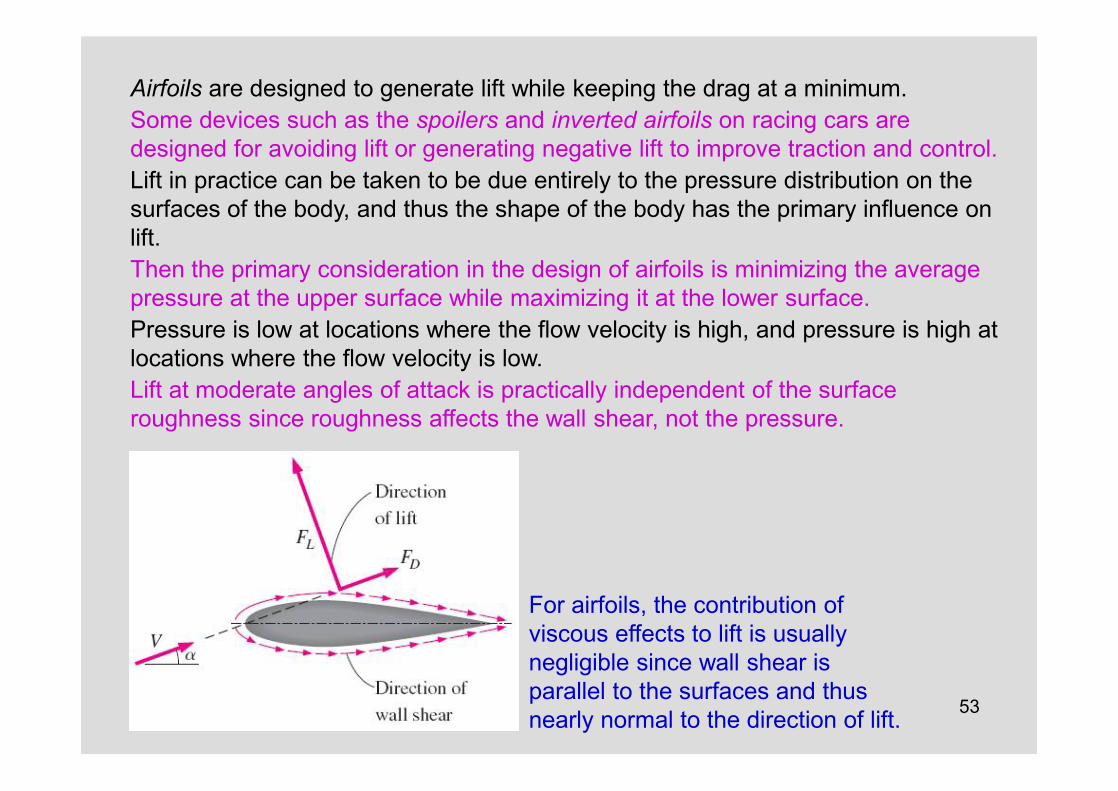
Airfoils are designed to generate lift while keeping the drag at a minimum. Some devices such as the spoilers and inverted airfoils on racing cars aredesigned for avoiding lift or generating negative lift to improve traction and control.Lift in practice can be taken to be due entirely to the pressure distribution on the surfaces of the body, and thus the shape of the body has the primary influence on lift. Then the primary consideration in the design of airfoils is minimizing the averagepressure at the upper surface while maximizing it at the lower surface.Pressure is low at locations where the flow velocity is high, and pressure is high at locations where the flow velocity is low.Lift at moderate angles of attack is practically independent of the surfaceroughness since roughness affects the wall shear, not the pressure.
For airfoils, the contribution ofviscous effects to lift is usuallynegligible since wall shear is parallel to the surfaces and thus nearly normal to the direction of lift.
54
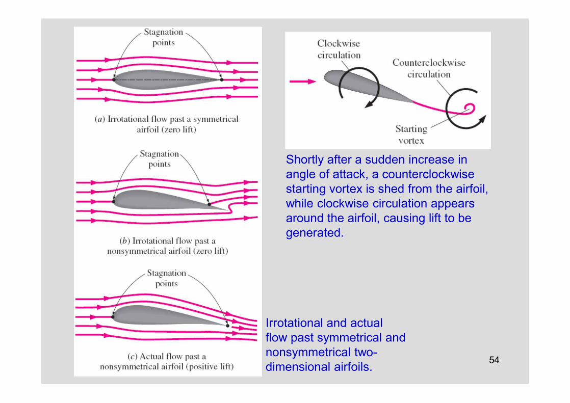
Irrotational and actual flow past symmetrical and nonsymmetrical two-dimensional airfoils.
Shortly after a sudden increase inangle of attack, a counterclockwisestarting vortex is shed from the airfoil,while clockwise circulation appearsaround the airfoil, causing lift to be generated.

55
It is desirable for airfoils to generate the most lift while producing the least drag. Therefore, a measure of performance for airfoils is the lift-to-drag ratio, which is equivalent to the ratio of the lift-to-drag coefficients CL/CD.
The variation of the lift-to-drag ratio with angle of attack for a two-dimensional airfoil.
The CL/CD ratio increases with the angle of attack until the airfoil stalls, and the value of the lift-to-drag ratio can be ofthe order of 100 for a two-dimensional airfoil.

56
One way to change the lift and drag characteristics of an airfoil is to change the angle of attack. On an airplane, the entire plane is pitched up to increase lift, since the wings are fixed relative to the fuselage.Another approach is to change the shape of the airfoil by the use of movable leading edge and trailing edge flaps. The flaps are used to alter the shape of the wings during takeoff and landing to maximize lift at low speeds.Once at cruising altitude, the flaps are retracted, and the wing is returned to its “normal” shape with minimal drag coefficient and adequate lift coefficient to minimize fuel consumption while cruising at a constant altitude. Note that even a small lift coefficient can generate a large lift force during normal operation because of the large cruising velocities of aircraft and the proportionality of lift to the square of flow velocity.
The lift and drag characteristics of anairfoil during takeoff and landing can be changed by changing the shape of the airfoil by the use of movable flaps.

57
Effect of flaps on the lift and drag coefficients of an airfoil.
The maximum lift coefficient increases from about 1.5 for the airfoil with no flaps to 3.5 for the double-slotted flap case. The maximum drag coefficient increases from about 0.06 for the airfoil with no flaps to about 0.3 for the double-slotted flap case.The angle of attack of the flaps can be increased to maximize the lift coefficient.
58
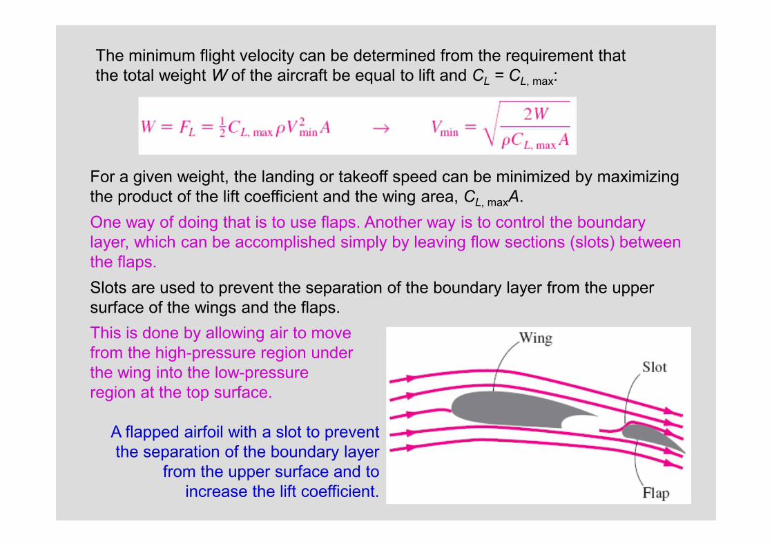
The minimum flight velocity can be determined from the requirement thatthe total weight W of the aircraft be equal to lift and CL = CL, max:
A flapped airfoil with a slot to preventthe separation of the boundary layer
from the upper surface and to increase the lift coefficient.
For a given weight, the landing or takeoff speed can be minimized by maximizingthe product of the lift coefficient and the wing area, CL, maxA. One way of doing that is to use flaps. Another way is to control the boundarylayer, which can be accomplished simply by leaving flow sections (slots) between the flaps.Slots are used to prevent the separation of the boundary layer from the upper surface of the wings and the flaps.This is done by allowing air to move from the high-pressure region under the wing into the low-pressureregion at the top surface.
59
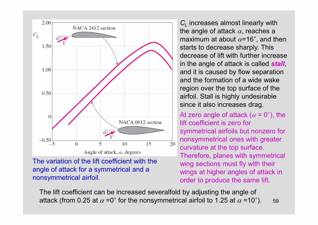
The variation of the lift coefficient with the angle of attack for a symmetrical and a nonsymmetrical airfoil.
CL increases almost linearly with the angle of attack a, reaches amaximum at about a=16°, and then starts to decrease sharply. This decrease of lift with further increase in the angle of attack is called stall, and it is caused by flow separation and the formation of a wide wakeregion over the top surface of the airfoil. Stall is highly undesirable since it also increases drag.At zero angle of attack (a = 0°), thelift coefficient is zero forsymmetrical airfoils but nonzero for nonsymmetrical ones with greatercurvature at the top surface.Therefore, planes with symmetrical wing sections must fly with theirwings at higher angles of attack in order to produce the same lift.
The lift coefficient can be increased severalfold by adjusting the angle of attack (from 0.25 at a =0° for the nonsymmetrical airfoil to 1.25 at a =10°).

60
The drag coefficient increases with the angle of attack, often exponentially.Therefore, large angles of attack should be used sparingly for short periods of time for fuel efficiency.
The variation of the drag coefficient of an airfoil with the angle of attack.
61
Finite-Span Wings and Induced Drag
For airplane wings and other airfoils of finite span, the end effects at the tips become important because of the fluid leakage between the lower and upper surfaces.
The pressure difference between the lower surface (highpressure region) and the upper surface (low-pressure region) drives the fluid at the tips upward while the fluid is swept toward the back because of the relative motion between the fluid and the wing.
This results in a swirling motion that spirals along the flow, called the tip vortex, at the tips of both wings.
Vortices are also formed along the airfoil between the tips of the wings.
These distributed vortices collect toward the edges after being shed from the trailing edges of the wings and combine with the tip vortices to form two streaks of powerful trailing vortices along the tips of the wings

62
Trailing vortices visualized in various ways: (a) Smoke streaklines in a wind tunnel show vortex cores leaving the trailing edge of a rectangular wing; (b) Four contrails initially formed by condensation of water vapor in the low pressure region behind the jet engines eventually merge into the two counter-rotating trailing vortices that persist very far downstream; (c) A crop duster flies through smoky air which swirls around in one of the tip vortices from the aircraft's wing.
63
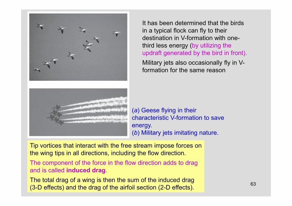
(a) Geese flying in their characteristic V-formation to save energy.(b) Military jets imitating nature.
It has been determined that the birds in a typical flock can fly to their destination in V-formation with one-third less energy (by utilizing the updraft generated by the bird in front). Military jets also occasionally fly in V-formation for the same reason
Tip vortices that interact with the free stream impose forces on the wing tips in all directions, including the flow direction. The component of the force in the flow direction adds to drag and is called induced drag.The total drag of a wing is then the sum of the induced drag (3-D effects) and the drag of the airfoil section (2-D effects).
64
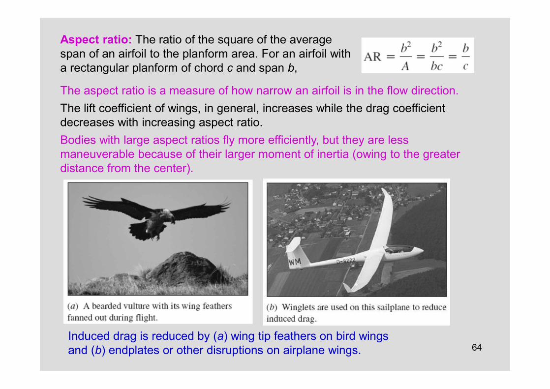
Aspect ratio: The ratio of the square of the average span of an airfoil to the planform area. For an airfoil with a rectangular planform of chord c and span b,
The aspect ratio is a measure of how narrow an airfoil is in the flow direction.The lift coefficient of wings, in general, increases while the drag coefficient decreases with increasing aspect ratio.Bodies with large aspect ratios fly more efficiently, but they are less maneuverable because of their larger moment of inertia (owing to the greater distance from the center).
Induced drag is reduced by (a) wing tip feathers on bird wingsand (b) endplates or other disruptions on airplane wings.

65
Lift Generated by SpinningMagnus effect: The phenomenon of producing lift by the rotation of a solid body.When the ball is not spinning, the lift is zero because of top–bottom symmetry. But when the cylinder is rotated about its axis, the cylinder drags some fluid around because of the no-slip condition and the flow field reflects the superposition of the spinning and nonspinning flows.
Generation of lift on a rotating circular cylinder for the case of “idealized” potential flow (the actual flow involves flow separation in the wake region).

66
Note that the lift coefficient strongly depends on the rate of rotation, especially at low angular velocities. The effect of the rate of rotation on the drag coefficient is small. Roughness also affects the drag and lift coefficients. In a certain range of Reynolds number, roughness produces the desirable effect of increasing the lift coefficient while decreasing the drag coefficient. Therefore, golf balls with the right amount of roughness travel higher and farther than smooth balls for the same hit.

67

68

69
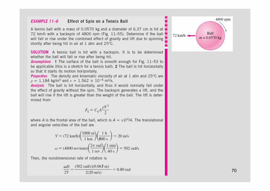
70
71

72The Wright Brothers take flight at Kitty Hawk.
While they cannot be credited with developing the concepts of lift and drag, they usedthem to achieve the first powered, manned, heavier-than-air, controlled flight.
They succeeded, while so many before them failed, because they evaluated and designed parts separately.
Before the Wrights, experimenters were building and testing whole airplanes.
The Wright Brothers are truly the most impressive engineering team of all time.Self-taught, they were well informed of the contemporary theory and practicein aeronautics. They both corresponded with other leaders in the field and published in technical journals.
73
Summary• Introduction• Drag and Lift• Friction and Pressure Drag
ü Reducing Drag by Streamliningü Flow Separation
• Drag Coefficients of Common Geometriesü Biological Systems and Dragü Drag Coefficients of Vehiclesü Superposition
• Parallel Flow Over Flat Platesü Friction Coefficient
• Flow Over Cylinders and Spheresü Effect of Surface Roughness
• Liftü Finite-Span Wings and Induced Dragü Lift Generated by Spinning
Related Documents