EEL6935 Advanced MEMS 2005 H. Xie 1 Lecture 20 Optical MEMS (2) Agenda: MOEMS Introduction Micromirrors 3/30/2005 EEL6935 Advanced MEMS (Spring 2005) Instructor: Dr. Huikai Xie EEL6935 Advanced MEMS 2005 H. Xie 2 Optical MEMS Topics Introduction to MOEMS Optical bench on chip; Smart dust; Optical communications Optical MEMS Devices Reflective – Micromirrors Refractive – Microlenses – Microprisms Diffractive – Microgratings – Microlenses (Fresnel) Waveguides Interference-based – Filters – Tunable VCSELs – Microspectrometers Uncooled Infrared Detectors Photonic crystals MEMS-based Optical Imaging

Welcome message from author
This document is posted to help you gain knowledge. Please leave a comment to let me know what you think about it! Share it to your friends and learn new things together.
Transcript
EEL6935 Advanced MEMS 2005 H. Xie 1
Lecture 20Optical MEMS (2)
Agenda:
MOEMS Introduction
Micromirrors
3/30/2005
EEL6935 Advanced MEMS (Spring 2005) Instructor: Dr. Huikai Xie
EEL6935 Advanced MEMS 2005 H. Xie 2
Optical MEMS TopicsIntroduction to MOEMS
Optical bench on chip; Smart dust; Optical communicationsOptical MEMS Devices
Reflective– Micromirrors
Refractive– Microlenses– Microprisms
Diffractive– Microgratings– Microlenses (Fresnel)
WaveguidesInterference-based
– Filters– Tunable VCSELs– Microspectrometers
Uncooled Infrared DetectorsPhotonic crystals
MEMS-based Optical Imaging
EEL6935 Advanced MEMS 2005 H. Xie 3
Today’s Topic
Introduction to MOEMSOptical bench on chipSmart dustOptical communications
Electrostatic mirrorsParallel-plateVertical comb drivesLateral comb drive with a vertical lever
Fabrication Processes– Thin-film– Bulk silicon
AssemblyIntegrated
EEL6935 Advanced MEMS 2005 H. Xie 4
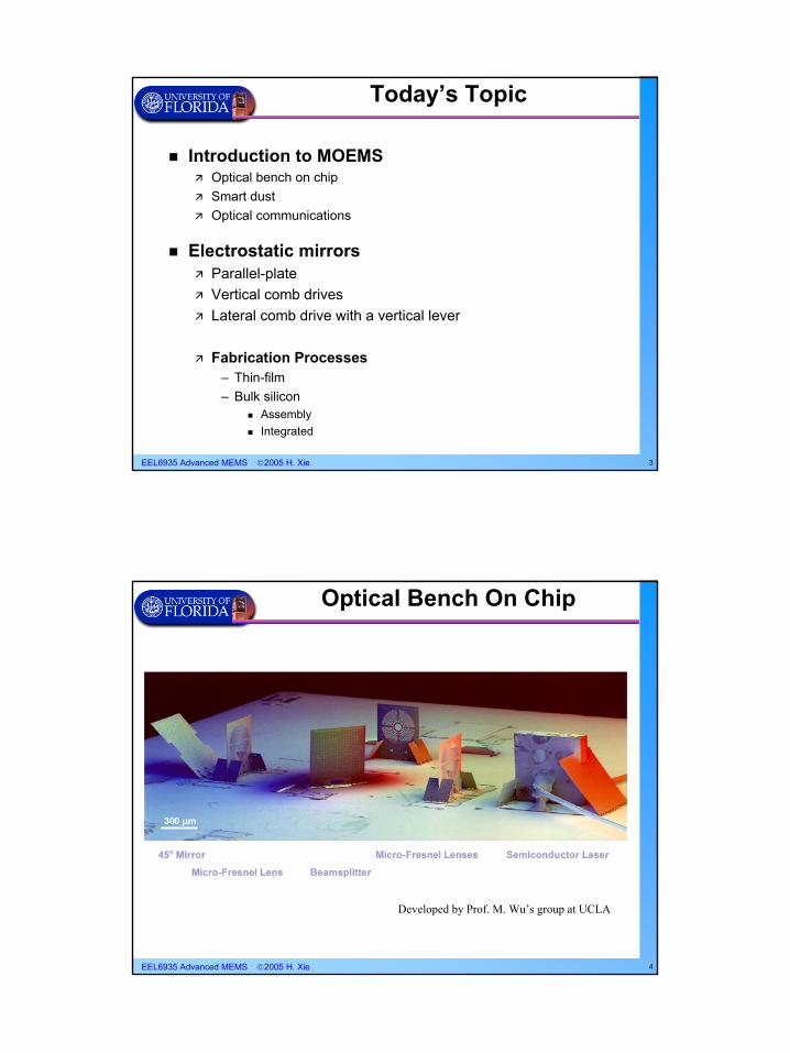
Developed by Prof. M. Wu’s group at UCLA
Optical Bench On Chip
EEL6935 Advanced MEMS 2005 H. Xie 5
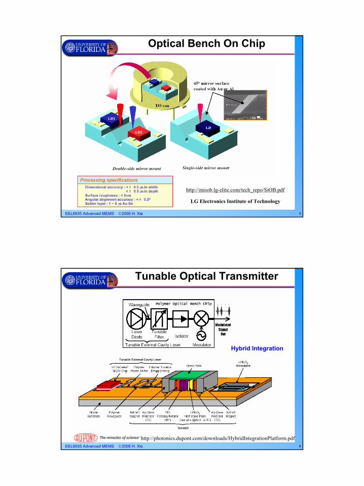
http://misob.lg-elite.com/tech_repo/SiOB.pdf
LG Electronics Institute of Technology
Optical Bench On Chip
EEL6935 Advanced MEMS 2005 H. Xie 6
Hybrid Integration
http://photonics.dupont.com/downloads/HybridIntegrationPlatform.pdf
Tunable Optical Transmitter
EEL6935 Advanced MEMS 2005 H. Xie 7
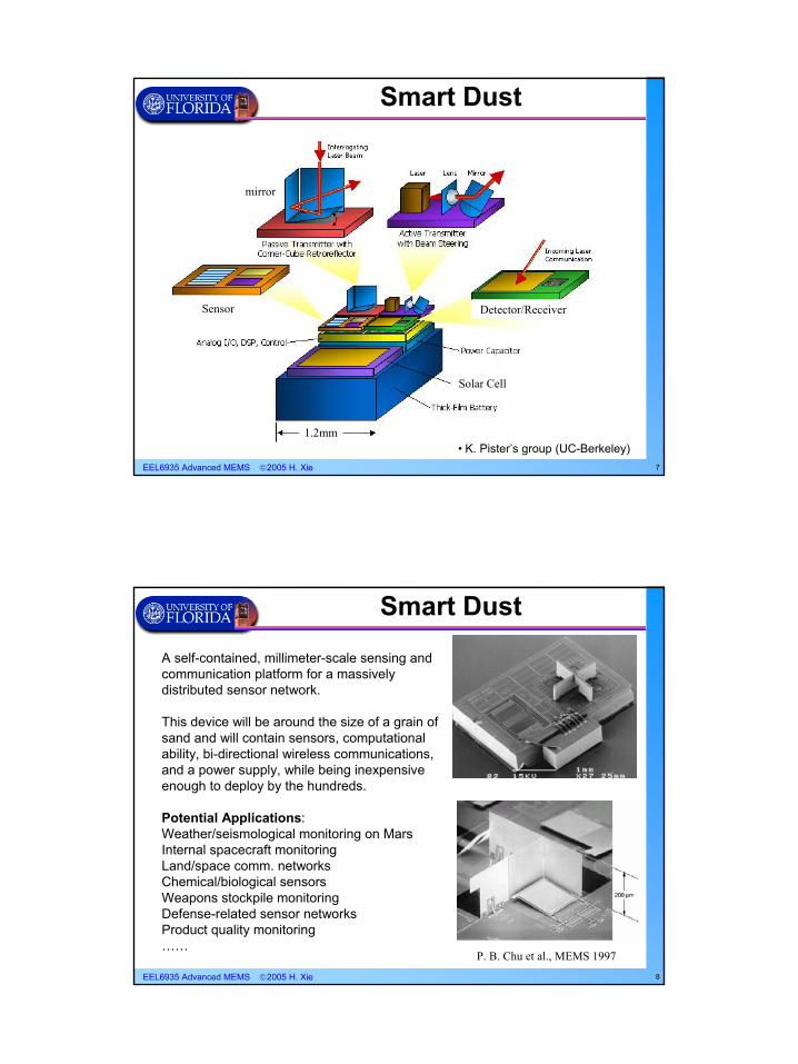
Smart Dust
1.2mm
mirror
Sensor Detector/Receiver
Solar Cell
• K. Pister’s group (UC-Berkeley)
EEL6935 Advanced MEMS 2005 H. Xie 8
Smart Dust
A self-contained, millimeter-scale sensing and communication platform for a massively distributed sensor network.
This device will be around the size of a grain of sand and will contain sensors, computational ability, bi-directional wireless communications, and a power supply, while being inexpensive enough to deploy by the hundreds.
Potential Applications:Weather/seismological monitoring on MarsInternal spacecraft monitoringLand/space comm. networksChemical/biological sensorsWeapons stockpile monitoringDefense-related sensor networksProduct quality monitoring……
P. B. Chu et al., MEMS 1997
EEL6935 Advanced MEMS 2005 H. Xie 9
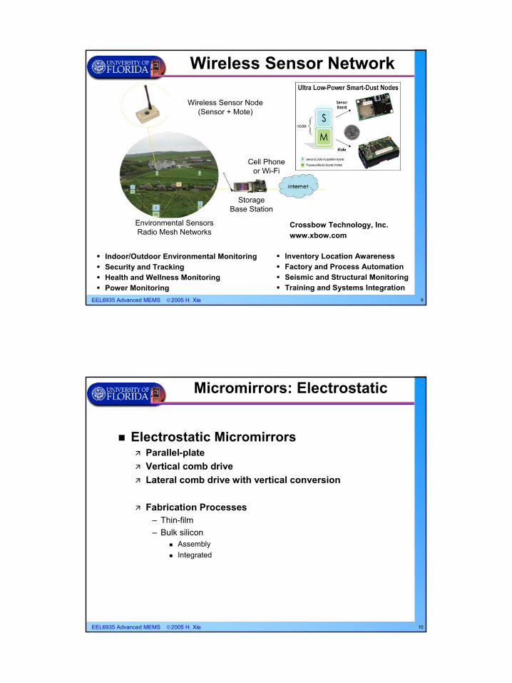
Inventory Location AwarenessFactory and Process AutomationSeismic and Structural MonitoringTraining and Systems Integration
Wireless Sensor Network
Indoor/Outdoor Environmental MonitoringSecurity and Tracking Health and Wellness MonitoringPower Monitoring
Cell Phoneor Wi-Fi
Storage Base Station
Environmental SensorsRadio Mesh Networks
Wireless Sensor Node(Sensor + Mote)
Crossbow Technology, Inc.www.xbow.com
EEL6935 Advanced MEMS 2005 H. Xie 10
Micromirrors: Electrostatic
Electrostatic MicromirrorsParallel-plateVertical comb driveLateral comb drive with vertical conversion
Fabrication Processes– Thin-film– Bulk silicon
AssemblyIntegrated
EEL6935 Advanced MEMS 2005 H. Xie 11
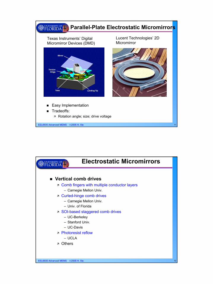
Easy ImplementationTradeoffs:
Rotation angle; size; drive voltage
Texas Instruments’ Digital Micromirror Devices (DMD)
Parallel-Plate Electrostatic Micromirrors
Lucent Technologies’ 2D Micromirror
EEL6935 Advanced MEMS 2005 H. Xie 12
Electrostatic Micromirrors
Vertical comb drivesComb fingers with multiple conductor layers
– Carnegie Mellon Univ.Curled-hinge comb drives
– Carnegie Mellon Univ.– Univ. of Florida
SOI-based staggered comb drives– UC-Berkeley– Stanford Univ.– UC-Davis
Photoresist reflow– UCLA
Others
EEL6935 Advanced MEMS 2005 H. Xie 13
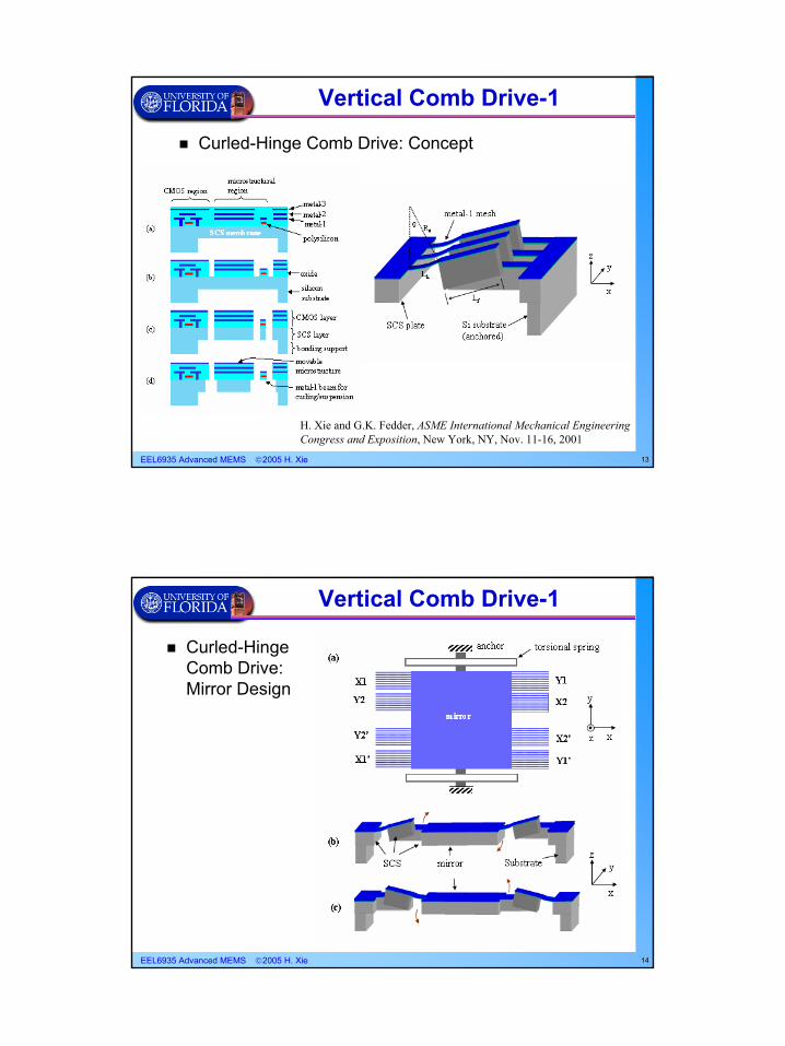
Vertical Comb Drive-1
H. Xie and G.K. Fedder, ASME International Mechanical Engineering Congress and Exposition, New York, NY, Nov. 11-16, 2001
Curled-Hinge Comb Drive: Concept
EEL6935 Advanced MEMS 2005 H. Xie 14
Vertical Comb Drive-1
Curled-Hinge Comb Drive: Mirror Design
EEL6935 Advanced MEMS 2005 H. Xie 15
Vertical Comb Drive-1
22cos1
22V
ddC
lNV
dzdCNFz ⋅⋅
⋅⋅=⋅⋅=
αα
( ) ( ) ( ) ( )2210
2 1211
21 zzzzzA ol ∆−++
−=
−=
αθαθα
tantan
( ) ( )gA
Cαε
α 0=
H. Xie et al, Journal of MEMS, 2002.
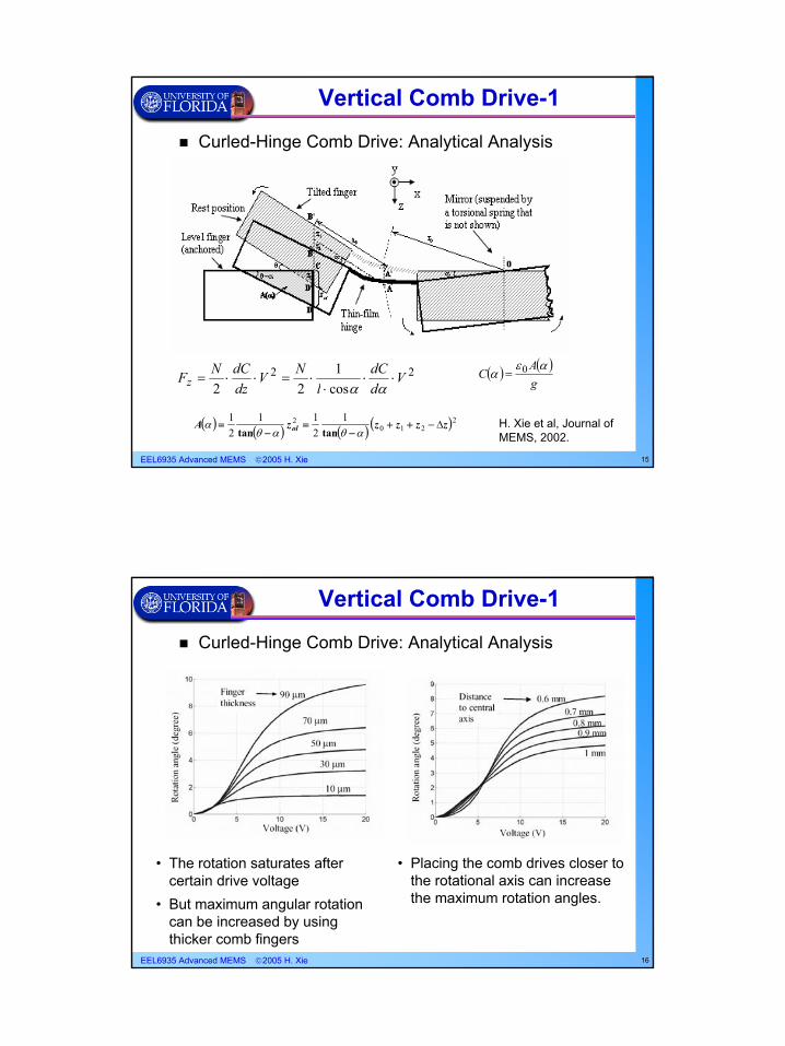
Curled-Hinge Comb Drive: Analytical Analysis
EEL6935 Advanced MEMS 2005 H. Xie 16
Vertical Comb Drive-1
Curled-Hinge Comb Drive: Analytical Analysis
• The rotation saturates after certain drive voltage
• But maximum angular rotation can be increased by using thicker comb fingers
• Placing the comb drives closer to the rotational axis can increase the maximum rotation angles.
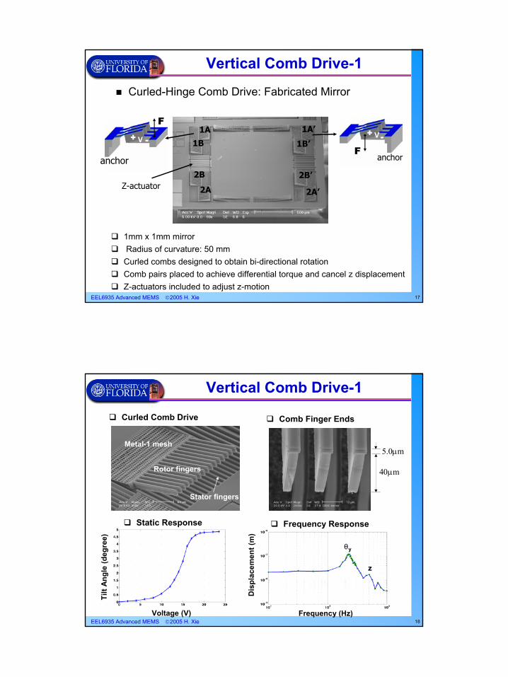
EEL6935 Advanced MEMS 2005 H. Xie 17
1mm x 1mm mirrorRadius of curvature: 50 mm
Curled combs designed to obtain bi-directional rotationComb pairs placed to achieve differential torque and cancel z displacementZ-actuators included to adjust z-motion
1B
1A’
2B
1B’
1A
2B’
2A’2A
anchor anchor
Z-actuator
+ -V
F+ -V
F
Vertical Comb Drive-1
Curled-Hinge Comb Drive: Fabricated Mirror
EEL6935 Advanced MEMS 2005 H. Xie 18
Stator fingers
Rotor fingers
Metal-1 mesh
Curled Comb Drive Comb Finger Ends
5.0µm
40µm
z
θy
Static Response Frequency Response
Frequency (Hz)Voltage (V)
Dis
plac
emen
t (m
)
Tilt
Ang
le (d
egre
e)
Vertical Comb Drive-1
EEL6935 Advanced MEMS 2005 H. Xie 19
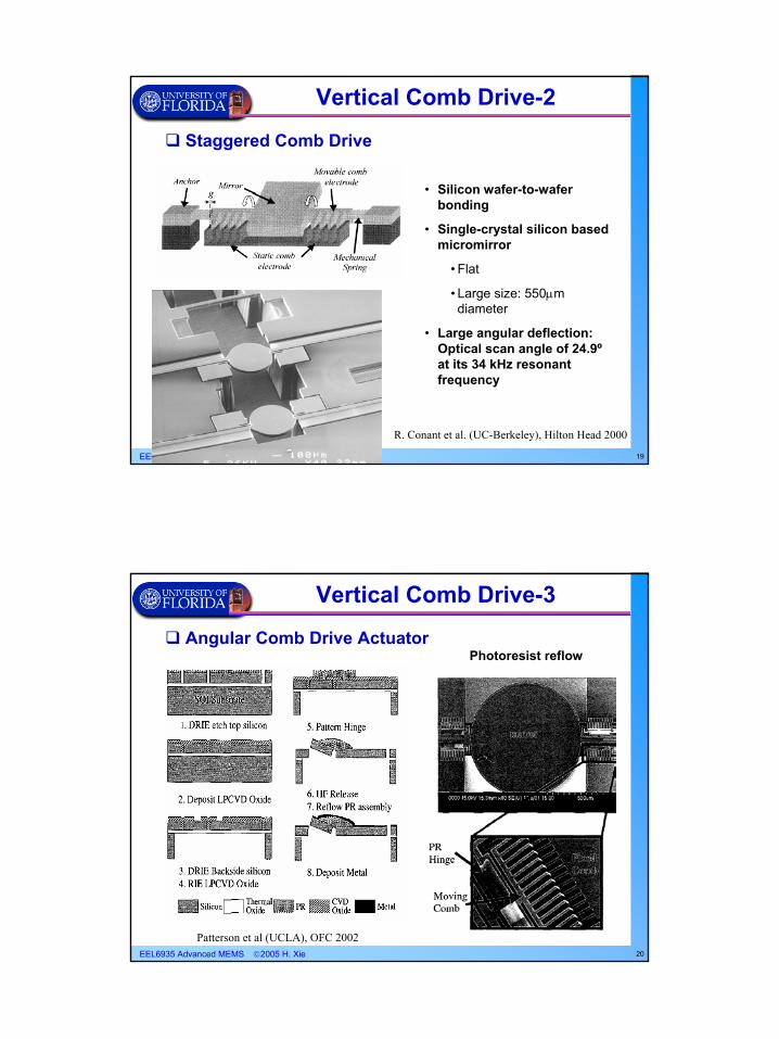
Staggered Comb Drive
R. Conant et al. (UC-Berkeley), Hilton Head 2000
Vertical Comb Drive-2
• Silicon wafer-to-wafer bonding
• Single-crystal silicon based micromirror
• Flat
• Large size: 550µm diameter
• Large angular deflection: Optical scan angle of 24.9ºat its 34 kHz resonant frequency
EEL6935 Advanced MEMS 2005 H. Xie 20
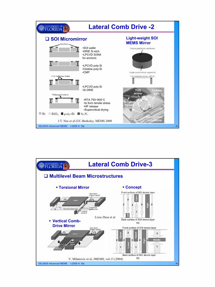
Angular Comb Drive Actuator
Patterson et al (UCLA), OFC 2002
Vertical Comb Drive-3
Photoresist reflow

EEL6935 Advanced MEMS 2005 H. Xie 21
Post-MUMPs DRIE process
Vertical Comb Drive-4
Piyawattammetha et al (UCLA), OFC 2003
• Mirror diameter: 1mm • Mirror radius of curvature: 40cm• +/-6° at 55 V d.c.
• Post-MUMPs process• Backside DRIE etch• Wet etch (BHF) for release• Single-crystal silicon structures• Manually assemble the tilt fingers using latches
EEL6935 Advanced MEMS 2005 H. Xie 22
Buckled Comb Drive
• Vertically buckled bridge• Wet etch SiO2• Poly-Si as HF etching mask
Sasaki et al (Tohoku U.), JMEMS, vol.13 (2004)
Vertical Comb Drive-5

EEL6935 Advanced MEMS 2005 H. Xie 23
Electrostatic Micromirrors
Lateral Comb DrivesHinges
– Sandia– UC-Berkeley – UCLA– …
Vertical levers– UC-Berkeley– …
EEL6935 Advanced MEMS 2005 H. Xie 24
• Gear Speed Reduction Unit• Micromirror and Drive Mechanism
Lateral Comb Drive -1
Hinged Thin-film Micromirror(Sandia National Lab.)
EEL6935 Advanced MEMS 2005 H. Xie 25
SOI Micromirror
Lateral Comb Drive -2
•SOI wafer•DRIE Si etch•LPCVD Si3N4 for anchors
•LPCVD poly-Si•Oxidize poly-Si•CMP
•LPCVD poly-Si•Si DRIE
•RTA 750~900°C•to form tensile stress•HF release•Supercritical drying
J.T. Nee et al (UC-Berkeley, MEMS 2000
Light-weight SOI MEMS Mirror
EEL6935 Advanced MEMS 2005 H. Xie 26
Torsional Mirror
Multilevel Beam Microstructures
V. Milanovic et al, JMEMS, vol.13 (2004)
Vertical Comb-Drive Mirror
Concept
Lateral Comb Drive-3
Lixia Zhou et al
EEL6935 Advanced MEMS 2005 H. Xie 27
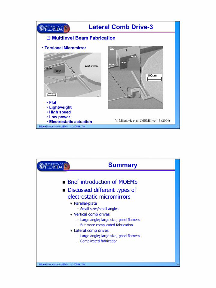
• Torsional Micromirror
Multilevel Beam Fabrication
• Flat• Lightweight• High speed• Low power• Electrostatic actuation V. Milanovic et al, JMEMS, vol.13 (2004)
Lateral Comb Drive-3
EEL6935 Advanced MEMS 2005 H. Xie 28
Brief introduction of MOEMSDiscussed different types of electrostatic micromirrors
Parallel-plate– Small sizes/small angles
Vertical comb drives– Large angle; large size; good flatness– But more complicated fabrication
Lateral comb drives– Large angle; large size; good flatness– Complicated fabrication
Summary
Related Documents


![Optical MEMS for Lightwave Communicationnanophotonics.eecs.berkeley.edu/Publications... · have focused on the development of optical MEMS devices and fabrication technologies [7]–[10].](https://static.cupdf.com/doc/110x72/5f92c214e2beb91e807adccc/optical-mems-for-lightwave-commun-have-focused-on-the-development-of-optical-mems.jpg)