T his month, we’ll add yet another motor and motor driver project to the pages of SERVO. The motor in the spotlight this time around is a direct descendent of common universal brushed DC motors. However, this motor type contains no brushes as its brushes have been replaced by Hall effect sensors and electronic circuitry. A brushed DC motor contains a set of brushes, a stator assembly, and a rotor assembly. Commutation — as it relates to brushed DC motors — is the process of switching current and thus, magnetic fields between the stator assembly and rotor assembly of the motor. The motor brushes play a large part in the process of commutation as the position of the brushes (like the stator) is constant with respect to the rotor’s magnetic fields. Thus, the brushes are actually part of the motor’s stator assembly. The magnetic fields of the stator always react with the commutating magnetic fields of the rotor in such a way as to coerce rotary motion via the motor’s rotor shaft. Our new motor type has no stationary brushes that provide a reference point for commutation. Instead, the motor type we’re about to discuss contains Hall effect sensors, which are positioned for use as commutation reference points by the brush replacement circuitry. This type of motor is called a brushless DC motor or just BLDC. After we go to school on this new motor, we’re going to design a microcontroller-based BLDC motor driver circuit that takes the place of the Hall effect sensors. BLDC 101 As you would imagine, the absence of brushes in a BLDC motor does have physical and electrical advantages. On the whole, BLDC motors last longer and run quieter acoustically and electrically than comparable universal DC motors. Pound for pound, a BLDC motor can deliver higher torque than its brushed counterpart. In addition to being more reliable, quieter, and stronger, BLDC motors have the ability to run faster than universal brushed DC motors while requiring less maintenance. BLDC motors are turning in automobiles, kitchen appliances, medical equipment, and aircraft. If you have one of those new front-loading washing machines, it’s a good bet that a BLDC motor is spinning the tub. These motors can also be found spinning diskettes and hard drive platters. The power-to-weight ratio of BLDC motors make them very popular for use in model aircraft. If BLDC motor technology is soaring around in flying robots, you can bet there’s an application for them in land-roving robotic manifestations. I attempted to disassemble the BLDC motor you see in Photo 1 with no joy. I suspect that its components are sealed to preserve the integrity of the positioning of the motor’s integral Hall sensors. I didn’t have a second motor on hand. So, I didn’t work too hard at pulling it apart. The model BLY171S-24V-4000 BLDC motor shown in Photo 1 is manufactured by Anaheim Automation. This particular motor has a permanent magnet rotor, a three-phase stator, and a built-in trio of Hall sensors. Picking apart the model number tells us that this motor is a NEMA size 17 type BLDC motor. The 1S denotes a single shaft motor with 11 oz-in of continuous stall torque. The BLY171S-24V-4000’s motor windings are rated for 24 volts and are able to spin the rotor shaft at 4,000 RPM. The BLY (for short) connects to the outside world using a standard eight-wire BLDC motor scheme. Three of the 30 SERVO 12.2008 I f you were to go back and survey past SERVO articles that I have written, you would probably conclude that I have this thing about motors and motor drivers. For instance, we recently tackled Universal Motors and constructed a Universal Motor controller. I also presented more than one SERVO stepper motor controller project. In these pages, we’ve driven linear actuators, rotated hobby servo rotors, and built circuitry to oversee the direction and speed of simple brushed DC motors. Photo 1. This BLDC motor comes ready to work with drive circuitry that employs the use of its built-in Hall effect sensors. These sensors are ignored when the motor is spun using sensorless BLDC motor drive techniques. LEARNING TO DRIVE: THE BLDC MOTOR By Fred Eady

Welcome message from author
This document is posted to help you gain knowledge. Please leave a comment to let me know what you think about it! Share it to your friends and learn new things together.
Transcript
This month, we’ll add yet another motor and motordriver project to the pages of SERVO. The motor inthe spotlight this time around is a direct descendent
of common universal brushed DC motors. However, thismotor type contains no brushes as its brushes have beenreplaced by Hall effect sensors and electronic circuitry. Abrushed DC motor contains a set of brushes, a statorassembly, and a rotor assembly. Commutation — as itrelates to brushed DC motors — is the process of switchingcurrent and thus, magnetic fields between the stator assembly and rotor assembly of the motor. The motorbrushes play a large part in the process of commutation asthe position of the brushes (like the stator) is constant withrespect to the rotor’s magnetic fields. Thus, the brushes areactually part of the motor’s stator assembly.
The magnetic fields of the stator always react with thecommutating magnetic fields of the rotor in such a way as to coerce rotary motion via the motor’s rotor shaft. Our
new motor type has nostationary brushes thatprovide a reference pointfor commutation.Instead, the motor typewe’re about to discusscontains Hall effect sensors, which are positioned for use ascommutation referencepoints by the brushreplacement circuitry.This type of motor iscalled a brushless DCmotor or just BLDC. After we go to school onthis new motor, we’regoing to design a microcontroller-basedBLDC motor driver circuit
that takes the place of the Hall effect sensors.
BLDC 101As you would imagine, the absence of brushes in a
BLDC motor does have physical and electrical advantages.On the whole, BLDC motors last longer and run quieteracoustically and electrically than comparable universal DCmotors. Pound for pound, a BLDC motor can deliver highertorque than its brushed counterpart. In addition to beingmore reliable, quieter, and stronger, BLDC motors have theability to run faster than universal brushed DC motors whilerequiring less maintenance. BLDC motors are turning inautomobiles, kitchen appliances, medical equipment, andaircraft. If you have one of those new front-loading washingmachines, it’s a good bet that a BLDC motor is spinning thetub. These motors can also be found spinning diskettes andhard drive platters. The power-to-weight ratio of BLDCmotors make them very popular for use in model aircraft. IfBLDC motor technology is soaring around in flying robots,you can bet there’s an application for them in land-rovingrobotic manifestations.
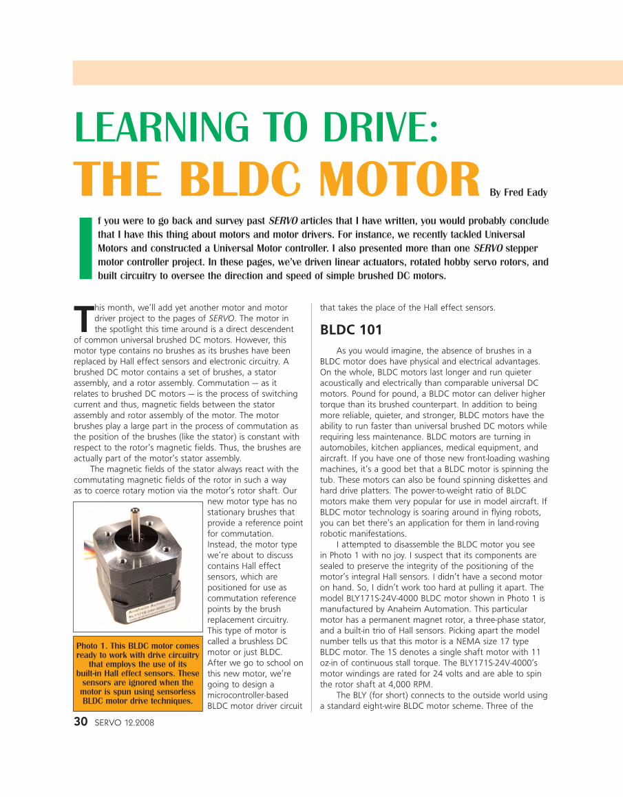
I attempted to disassemble the BLDC motor you see in Photo 1 with no joy. I suspect that its components aresealed to preserve the integrity of the positioning of themotor’s integral Hall sensors. I didn’t have a second motoron hand. So, I didn’t work too hard at pulling it apart. Themodel BLY171S-24V-4000 BLDC motor shown in Photo 1 ismanufactured by Anaheim Automation. This particularmotor has a permanent magnet rotor, a three-phase stator,and a built-in trio of Hall sensors. Picking apart the modelnumber tells us that this motor is a NEMA size 17 typeBLDC motor. The 1S denotes a single shaft motor with 11oz-in of continuous stall torque. The BLY171S-24V-4000’smotor windings are rated for 24 volts and are able to spinthe rotor shaft at 4,000 RPM.
The BLY (for short) connects to the outside world usinga standard eight-wire BLDC motor scheme. Three of the
30 SERVO 12.2008
If you were to go back and survey past SERVO articles that I have written, you would probably concludethat I have this thing about motors and motor drivers. For instance, we recently tackled UniversalMotors and constructed a Universal Motor controller. I also presented more than one SERVO steppermotor controller project. In these pages, we’ve driven linear actuators, rotated hobby servo rotors, andbuilt circuitry to oversee the direction and speed of simple brushed DC motors.
Photo 1. This BLDC motor comesready to work with drive circuitry
that employs the use of its built-in Hall effect sensors. These
sensors are ignored when themotor is spun using sensorlessBLDC motor drive techniques.
LEARNING TO DRIVE:THE BLDC MOTOR By Fred Eady
BLY’s motor interface wires are terminations for the threestator phases. The remaining five wires service the BLDCmotor’s built-in Hall effect sensors. Here’s how our BLYBLDC motor is wired:
Motor Phases:- Phase A: Yellow- Phase B: Red- Phase C: Black
Hall Effect Sensors:- Hall Effect Supply: Red- Hall Effect Sensor A: Blue- Hall Effect Sensor B: Green- Hall Effect Sensor C: White- Hall Effect Ground: Black
If we want to deploy the BLDC motor is a standard manner, the Hall effect sensors are used in the commutation process. In a sensorless BLDC motorimplementation, we’re only interested in the motor phasewiring. Sensorless motor control commutation is a productof the BLDC motor’s back electromotive force (BEMF),which is produced in the motor’s stator windings as a result of the movement of the rotor’s permanent magnetspast the stator coils. Before we formulate a method of getting rid of the Hall effect sensors, it would be helpful tounderstand how a BLDC motor works with them.
BLDC Operation 101Although we have identified only three major coils in
our BLDC motor, a typical three-phase BLDC motor containsa multi-coiled stator and a permanent magnet rotor. Themore stator coils one can cram into the stator assembly of a BLDC motor, the smaller the rotational steps. Smaller rotational steps result in less torque ripple. The same principle applies to the rotor. A BLDC motor’s rotor supportsan even number of permanent magnets. The more magneticpoles associated with the rotor, the smaller the rotationalsteps. You know the rest. Regardless of how many statorcoils and rotor magnets a BLDC motor has, we can still gain an understanding of how a BLDC motor works byexamining only three coils.
Like a stepper motor, a BLDC motor commutatesaccording to a predetermined coil activation sequence.That’s about where the similarity ends. Stepper motors havehigher step counts and require a higher operating voltage.BLDC motors are designed to operate with Hall effect commutation and variable voltage drive. Precise rotor alignment is not something a BLDC is particularly good at.Conversely, a stepper wants a constant voltage drive and isdesigned for precise angular positioning of its rotor.
A three phase BLDC motor has six discrete states ofcommutation. When the correct coil activation sequence ispresented to a BLDC, the motor shaft will rotate. Reversinga valid BLDC motor coil activation sequence will reverse the
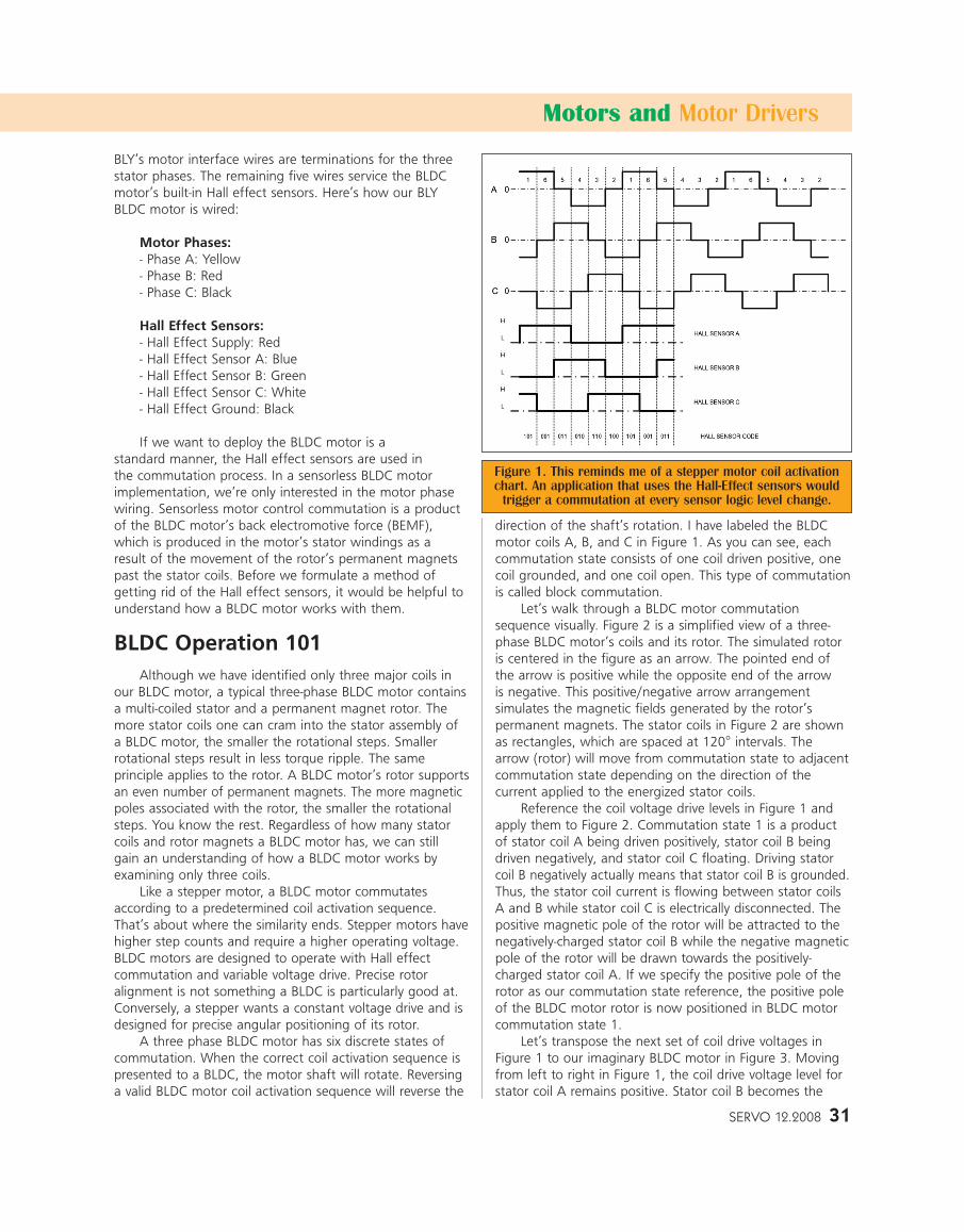
direction of the shaft’s rotation. I have labeled the BLDCmotor coils A, B, and C in Figure 1. As you can see, eachcommutation state consists of one coil driven positive, onecoil grounded, and one coil open. This type of commutationis called block commutation.
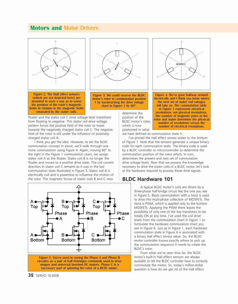
Let’s walk through a BLDC motor commutationsequence visually. Figure 2 is a simplified view of a three-phase BLDC motor’s coils and its rotor. The simulated rotoris centered in the figure as an arrow. The pointed end ofthe arrow is positive while the opposite end of the arrow is negative. This positive/negative arrow arrangement simulates the magnetic fields generated by the rotor’s permanent magnets. The stator coils in Figure 2 are shownas rectangles, which are spaced at 120° intervals. Thearrow (rotor) will move from commutation state to adjacentcommutation state depending on the direction of the current applied to the energized stator coils.
Reference the coil voltage drive levels in Figure 1 andapply them to Figure 2. Commutation state 1 is a productof stator coil A being driven positively, stator coil B beingdriven negatively, and stator coil C floating. Driving statorcoil B negatively actually means that stator coil B is grounded.Thus, the stator coil current is flowing between stator coilsA and B while stator coil C is electrically disconnected. Thepositive magnetic pole of the rotor will be attracted to thenegatively-charged stator coil B while the negative magneticpole of the rotor will be drawn towards the positively-charged stator coil A. If we specify the positive pole of therotor as our commutation state reference, the positive poleof the BLDC motor rotor is now positioned in BLDC motorcommutation state 1.
Let’s transpose the next set of coil drive voltages inFigure 1 to our imaginary BLDC motor in Figure 3. Movingfrom left to right in Figure 1, the coil drive voltage level forstator coil A remains positive. Stator coil B becomes the
SERVO 12.2008 31
Motors and Motor Drivers
Figure 1. This reminds me of a stepper motor coil activationchart. An application that uses the Hall-Effect sensors would
trigger a commutation at every sensor logic level change.
32 SERVO 12.2008
floater and the stator coil C drive voltage level transitionsfrom floating to negative. This stator coil drive voltage pattern forces the positive field of the rotor to movetowards the negatively charged stator coil C. The negativefield of the rotor is still under the influence of positively-charged stator coil A.
I think you get the idea. However, to set the BLDC commutation concept in stone, we’ll walk through onemore commutation using Figure 4. Again, moving 60° tothe right in the Figure 1 commutation chart, we assign stator coil A as the floater. Stator coil B is no longer thefloater and moves to a positive drive state. The coil currentdirection in stator coil C remains as it was in the last commutation state illustrated in Figure 3. Stator coil A iselectrically null and is powerless to influence the motion ofthe rotor. The magnetic forces of stator coils B and C now
determine the position of theBLDC motor’s rotor,which is now positioned in whatwe have defined as commutation state 5.
I’ve pinned the Hall effect sensor states to the bottomof Figure 1. Note that the sensors generate a unique binarycode for each commutation state. The binary code is usedby a BLDC controller or microcontroller to determine thecommutation position of the rotor which, in turn, determines the present and next set of commutation drive voltage levels. Now that we possess the knowledgenecessary to drive the stator coils of a BLDC motor, let’s lookat the hardware required to process those drive signals.
BLDC Hardware 101A typical BLDC motor’s coils are driven by a
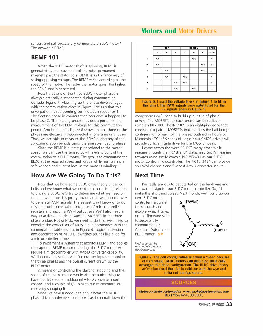
three-phase half-bridge circuit like the one you seein Figure 5. Block commutation with a twist is usedto drive this multi-phase collection of MOSFETs. Thetwist is PWM, which is applied only to the bottomMOSFETs. Applying the PWM there leaves the possibility of only one of the top transistors to betotally ON at any time. I’ve used the coil drive levels from the commutation chart in Figure 1 toformulate the hardware commutation chart you see in Figure 6. Just as in Figure 1, each hardwarecommutation state in Figure 6 is associated with a binary Hall effect sensor value. So, the BLDCmotor controller knows exactly where to pick upthe commutation sequence it needs to rotate theBLDC’s rotor.
From what we’ve seen thus far, the BLDCmotor’s built-in Hall effect sensors are always available to tell the BLDC controller how to correctlycommutate the motor. So, today’s million-dollarquestion is how do we get rid of the Hall effect
Motors and Motor Drivers
Figure 5. You’re used to seeing the Phase A and Phase B circuitry as a pair of half H-bridges commonly used to drive
stepper and universal brushed DC motors. Phase C is a necessary part of spinning the rotor of a BLDC motor.
Figure 4. We’ve gone halfway aroundelectrically and I think you know where
the next set of stator coil voltages will take us. The commutation table
in Figure 1 represents electrical revolutions, not physical revolutions.The number of magnetic poles in the
rotor and stator determine the physicalnumber of revolutions versus the number of electrical revolutions.
Figure 2. The Hall effect sensors(which are not depicted here) are
mounted in such a way as to sensethe position of the rotor’s magnetic
fields in relation to the magnetic fieldsemanated by the stator coils.
Figure 3. We could reverse the BLDCmotor’s rotor to commutation position
1 by backtracking the drive voltagechart in Figure 1 by 60°.
sensors and still successfully commutate a BLDC motor? The answer is BEMF.
BEMF 101When the BLDC motor shaft is spinning, BEMF is
generated by the movement of the rotor permanent magnets past the stator coils. BEMF is just a fancy way ofsaying opposing voltage. The BEMF varies according to thespeed of the motor. The faster the motor spins, the higherthe BEMF that is generated.
Recall that one of the three BLDC motor phases isalways electrically disconnected during commutation.Consider Figure 7. Matching up the phase drive voltageswith the commutation chart in Figure 6 tells us that thisdrive pattern is representing commutation sequence 4. The floating phase in commutation sequence 4 happens tobe phase C. The floating phase provides a portal for the measurement of the BEMF voltage for this commutationperiod. Another look at Figure 6 shows that all three of thephases are electrically disconnected at one time or another.Thus, we are able to measure the BEMF during any of thesix commutation periods using the available floating phase.
Since the BEMF is directly proportional to the motorspeed, we can use the sensed BEMF levels to control thecommutation of a BLDC motor. The goal is to commutate theBLDC at the required speed and torque while maintaining asafe voltage and current level in the motor’s windings.
How Are We Going To Do This?Now that we have some BLDC drive theory under our
belts and we know what we need to accomplish in relationto driving a BLDC, let’s try to determine what we need onthe hardware side. It’s pretty obvious that we’ll need a wayto generate PWM signals. The easiest way I know of to dothis is to push some values into a set of microcontroller registers and assign a PWM output pin. We’ll also need away to activate and deactivate the MOSFETs in the three-phase bridge. Not only do we need to do this, we’ll need toenergize the correct set of MOSFETs in accordance with thecommutation table laid out in Figure 6. Logical activationand deactivation of MOSFET switches sounds like a job fora microcontroller to me.
To implement a system that monitors BEMF and appliesthe captured BEMF to commutating, the BLDC motor willrequire a microcontroller with A-to-D converter capability.We’ll need at least four A-to-D converter inputs to monitorthe three phases and the overall current drawn by the BLDC motor.
A means of controlling the starting, stopping and thespeed of the BLDC motor would also be a nice thing tohave. So, let’s add an additional A-to-D converter inputchannel and a couple of I/O pins to our microcontroller-capability shopping list.
Since we have a good idea about what the BLDC phase driver hardware should look like, I can nail down the
components we’ll need to build up our trio of phase drivers. The MOSFETs for each phase can be realized using an IRF7309. The IRF7309 is an eight-pin device thatconsists of a pair of MOSFETs that matches the half-bridgeconfiguration of each of the phases outlined in Figure 5.Microchip’s TC446X series of Logic-Input CMOS drivers willprovide sufficient gate drive for the MOSFET pairs.
I came across the word “BLDC” many times while reading through the PIC18F2431 datasheet. So, I’m leaningtowards using the Microchip PIC18F2431 as our BLDCmotor control microcontroller. The PIC18F2431 can providesix PWM channels and five fast A-to-D converter inputs.
Next TimeI’m really anxious to get started on the hardware and
firmware design for our BLDC motor controller. So, I’ll make this short and sweet. Next month, we’ll build up our own BLDC motorcontroller hardwarefrom scratch andexplore what it takeson the firmware sideto successfully commutate ourAnaheim AutomationBLDC motor. SV
Fred Eady can be reached via email [email protected].
SERVO 12.2008 33
Motors and Motor Drivers
Figure 6. I used the voltage levels in Figure 1 to fill in this chart. The PWM signals were substituted for the
–V signals given in Figure 1.
Figure 7. The coil configuration is called a “wye” becauseof its Y shape. BLDC motors can also have their coils
arranged in a delta configuration. The BLDC drive theorywe’ve discussed thus far is valid for both the wye and
delta coil configurations.
Motor Anaheim Automation www.anaheimautomation.comBLY171S-24V-4000 BLDC
SOURCES
Related Documents