D a ik in E u r o p e Academ y Learning, our way Exercise Water pipe, Pump and Cooling Tower Selection

Learning, our way Exercise Water pipe, Pump and Cooling Tower Selection.
Dec 25, 2015
Welcome message from author
This document is posted to help you gain knowledge. Please leave a comment to let me know what you think about it! Share it to your friends and learn new things together.
Transcript

D a i k i n E u r o p e A c a d e m y
Learning, our way
ExerciseWater pipe, Pump and
Cooling Tower Selection

D a i k i n E u r o p e A c a d e m y
Learning, our way
Watercooled VRV Selection: VRV WII - Express
• Cooling Load per floor is 40 kW, Heat load 16.5 kW– 10 HP VRV unit gives >130% connection ratio– 20 HP VRV unit gives 80-110% connection ratio,
Depending on piping length– 30 HP VRV unit gives <66% connection ratio
20 Hp unit is selected

D a i k i n E u r o p e A c a d e m y
Learning, our wayCooling unit Selection
• Cooling tower, evaporative cooler or dry cooler?Approach: 8°C, mild climate.
Europe, small scale installation(No large water purification installation needed)
Type: Evaporative fluid coolersBrand Baltimore: Type VXI

D a i k i n E u r o p e A c a d e m y
Learning, our way
Cooling mode: (VRV express)• Total heating capacity available= 49.5W *4 • Total Power Input at 98% connection ratio = 9.0 kW *4• Total rejected heat = 4 *(49.5+9.0)= 234 kW• Total water flow (= max water flow )= 96 * 2* 4
= 768 l/min = 12.8 l/s • Range= EWC – LWC = rejected heat / (4.186 x water flow)
=177.6 / (4,186 x 12,8)= 4,37°C• EWC= cooling tower entering water temperature= 30 + 4,4 = 34,4°C• LWC= cooling tower leaving water temperature = 30 °C
Approach = LWC – WBT = 30°C – 22°C = 8°C
Calculations Evaporative Cooler Selection:

D a i k i n E u r o p e A c a d e m y
Learning, our way
Selection Evaporator
Determine the performance factor using the diagramsprovided by Baltimore:
Input: Range = 4.4 Approach = 8°C WBT = 22°C
Output: Pf = 5

D a i k i n E u r o p e A c a d e m y
Learning, our way
Evaporative cooler selection

D a i k i n E u r o p e A c a d e m y
Learning, our way
Heating mode:
• Total Heat capacity required= 63 kW *4
• Total Power Input = 6 kW *4• Total injected heat = 4 *(63-6)= 228 kW
Calculations Boiler Capacity:

D a i k i n E u r o p e A c a d e m y
Learning, our way
Water piping: water flow rates
• Each VRV has as design waterflow– 96 l/min per 10 Hp unit.
• Horizontal piping to indoor units:– 2 x 96 l/min = 192 l/min
• Vertical parts: Different sections A, B, C, D– Secton A: Only 1 20 HP unit: 192 l/min (=3,2l/s)– Section B: 2x 20 HP unit : 384 l/min (=6,4l/s)– Section C: 3x 20 HP unit, 576 l/min (=9,6l/s)– Section D: 1x 10 HP Sub-unit, 96l/min (=1,6l/s)– Section E: 4x 20 HP unit: 768 l/min (=12,8l/s)
• Reverse Return Distriubution
* *
A
B
C
DE
A
C
B
D a i k i n E u r o p e A c a d e m y
Learning, our way
Piping diameters
Reccomendations:
Pipe diameter (mm)
Velocity range (m/s)
125 2.1~2.7
50 ~ 100 1.2~2.1
Around 25 0.6~1.2
A
B
C
D
E

D a i k i n E u r o p e A c a d e m y
Learning, our way
Reference Path: Take worse case:3m C+B+C+horizontal: 3m A+B+C+horizontal
Linear Head Loss• Using Friction loss graph:
Opposite effect of joints
Comparable results!
Part: Flow rate (l/s)
Diameter (mm)
Water velocity (m/s)
Length (m)
Pressure loss per meter (Pa/m)=10mH2O/m
Total (mH2O)
A 3.2 50 1,5 2x5
+3
70 0,91
B 6.4 65 1.9 3 70 0,21C 9.6 80 1,5 3 50 0,15
D 1.6 40 0,9 2 x 1 50 0,1E 12.8 100 1.6 12 15 0,18
+3 +0.15
-0.21
* *
A
B
C
D
A
C
B
D a i k i n E u r o p e A c a d e m y
Learning, our way
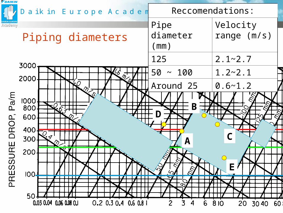
Water Pipe Design: Local Head losses
• Local friction losses: For 1 water route:– 3 branches “Straight Trough”- 2 x “Trough Branch” connection on main
line (2 for each 10 HP unit, speed )- 2 x “Trough Branch” Joint on indoor piping- 2x 3 elbow joints on indoor piping
• Straight line friction losses: – 4 x 3 m vertical piping, – 2 x 3 m indoor piping
* *
A
B
C
DE
A
C
B

D a i k i n E u r o p e A c a d e m y
Learning, our way
* *
A
B
C
DE
A
C
B
Local Head loss: Blue path
T joints “Straight Trough”• E to C
• C to B
• B to A
.
Partial head lossHtLocation:
Number ON
1 water path Equivalent piping length (m)
Pressure loss / m (mmH2O/m)
Pressure loss
(mH2O)
Elbows on A 2*2 + 1 5 * 1.6 70 0.56
Elbows on D 2*1 2 * 1.3 70 0.18
Elbows on E 2 2 * 1,3 70 0.18
T-joints Staight-tru (on main line)
3 1,7+1.7+1.4
70 0.34
T-joints Tru Branch (on main line)
1 5.7 70 0.40
T-joints Tru Branch (on horizontal line)
2 2.8+3.5 70 0.44
T joint “Trough Branch”•A to E
-1
+1
-0. 11
+ 5.7
•B to A•A to C
•E to C•C to B•C to E
vs Red path
+0.02
+0.29 4.2
+ 1.7
Total: +0.20

D a i k i n E u r o p e A c a d e m y
Learning, our wayPiping design – pump selection properties
H = Ha + Hf + Ht + Hk
Ht = Linear Head loss = 1.55 mH2OHa = Actual head (m H2O) = 0Ht = Partial friction loss = 2,23 m H2OHk = Internal friction loss = 2,7 mH2O
1 x 1 VRV 10 HP unit, at 96 l/minHk2 = Given, 5 mH2O
Total head loss= 11,48 mH2O at a flow rate of 768 l/min46 m3/hr
+0.14 mH2O
D a i k i n E u r o p e A c a d e m y
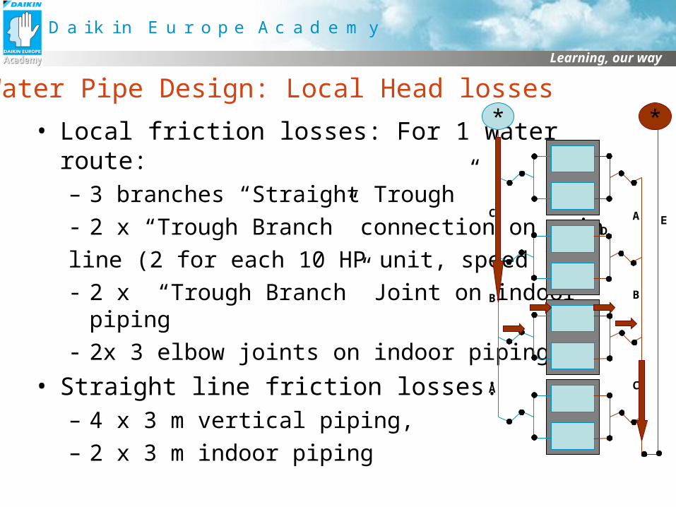
Learning, our wayWater piping design: Pump Pre-selection
LRC 406
D a i k i n E u r o p e A c a d e m y
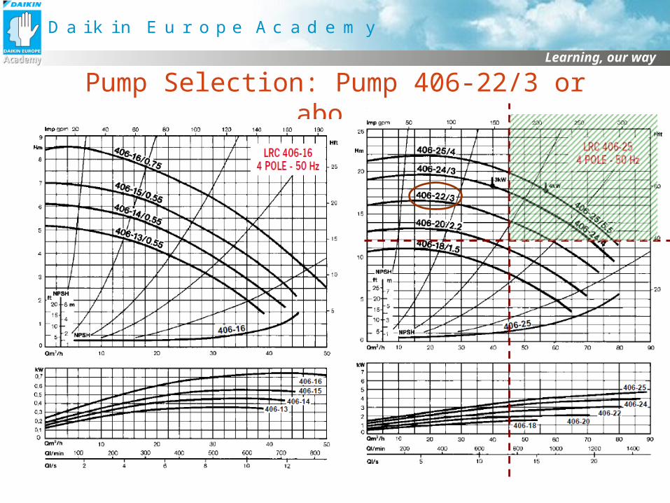
Learning, our wayPump Selection: Pump 406-22/3 or above
Related Documents